EP3733574B1 - Sheet feeder and control method for sheet feeder - Google Patents
Sheet feeder and control method for sheet feeder Download PDFInfo
- Publication number
- EP3733574B1 EP3733574B1 EP18893908.6A EP18893908A EP3733574B1 EP 3733574 B1 EP3733574 B1 EP 3733574B1 EP 18893908 A EP18893908 A EP 18893908A EP 3733574 B1 EP3733574 B1 EP 3733574B1
- Authority
- EP
- European Patent Office
- Prior art keywords
- sheet
- feed roller
- roller
- conveyance
- control unit
- Prior art date
- Legal status (The legal status is an assumption and is not a legal conclusion. Google has not performed a legal analysis and makes no representation as to the accuracy of the status listed.)
- Active
Links
Images









Classifications
-
- B—PERFORMING OPERATIONS; TRANSPORTING
- B65—CONVEYING; PACKING; STORING; HANDLING THIN OR FILAMENTARY MATERIAL
- B65H—HANDLING THIN OR FILAMENTARY MATERIAL, e.g. SHEETS, WEBS, CABLES
- B65H9/00—Registering, e.g. orientating, articles; Devices therefor
- B65H9/002—Registering, e.g. orientating, articles; Devices therefor changing orientation of sheet by only controlling movement of the forwarding means, i.e. without the use of stop or register wall
-
- B—PERFORMING OPERATIONS; TRANSPORTING
- B65—CONVEYING; PACKING; STORING; HANDLING THIN OR FILAMENTARY MATERIAL
- B65H—HANDLING THIN OR FILAMENTARY MATERIAL, e.g. SHEETS, WEBS, CABLES
- B65H3/00—Separating articles from piles
- B65H3/02—Separating articles from piles using friction forces between articles and separator
- B65H3/06—Rollers or like rotary separators
-
- B—PERFORMING OPERATIONS; TRANSPORTING
- B65—CONVEYING; PACKING; STORING; HANDLING THIN OR FILAMENTARY MATERIAL
- B65H—HANDLING THIN OR FILAMENTARY MATERIAL, e.g. SHEETS, WEBS, CABLES
- B65H5/00—Feeding articles separated from piles; Feeding articles to machines
- B65H5/06—Feeding articles separated from piles; Feeding articles to machines by rollers or balls, e.g. between rollers
- B65H5/062—Feeding articles separated from piles; Feeding articles to machines by rollers or balls, e.g. between rollers between rollers or balls
-
- B—PERFORMING OPERATIONS; TRANSPORTING
- B65—CONVEYING; PACKING; STORING; HANDLING THIN OR FILAMENTARY MATERIAL
- B65H—HANDLING THIN OR FILAMENTARY MATERIAL, e.g. SHEETS, WEBS, CABLES
- B65H7/00—Controlling article feeding, separating, pile-advancing, or associated apparatus, to take account of incorrect feeding, absence of articles, or presence of faulty articles
- B65H7/02—Controlling article feeding, separating, pile-advancing, or associated apparatus, to take account of incorrect feeding, absence of articles, or presence of faulty articles by feelers or detectors
-
- B—PERFORMING OPERATIONS; TRANSPORTING
- B65—CONVEYING; PACKING; STORING; HANDLING THIN OR FILAMENTARY MATERIAL
- B65H—HANDLING THIN OR FILAMENTARY MATERIAL, e.g. SHEETS, WEBS, CABLES
- B65H7/00—Controlling article feeding, separating, pile-advancing, or associated apparatus, to take account of incorrect feeding, absence of articles, or presence of faulty articles
- B65H7/02—Controlling article feeding, separating, pile-advancing, or associated apparatus, to take account of incorrect feeding, absence of articles, or presence of faulty articles by feelers or detectors
- B65H7/14—Controlling article feeding, separating, pile-advancing, or associated apparatus, to take account of incorrect feeding, absence of articles, or presence of faulty articles by feelers or detectors by photoelectric feelers or detectors
-
- B—PERFORMING OPERATIONS; TRANSPORTING
- B65—CONVEYING; PACKING; STORING; HANDLING THIN OR FILAMENTARY MATERIAL
- B65H—HANDLING THIN OR FILAMENTARY MATERIAL, e.g. SHEETS, WEBS, CABLES
- B65H7/00—Controlling article feeding, separating, pile-advancing, or associated apparatus, to take account of incorrect feeding, absence of articles, or presence of faulty articles
- B65H7/18—Modifying or stopping actuation of separators
-
- B—PERFORMING OPERATIONS; TRANSPORTING
- B65—CONVEYING; PACKING; STORING; HANDLING THIN OR FILAMENTARY MATERIAL
- B65H—HANDLING THIN OR FILAMENTARY MATERIAL, e.g. SHEETS, WEBS, CABLES
- B65H7/00—Controlling article feeding, separating, pile-advancing, or associated apparatus, to take account of incorrect feeding, absence of articles, or presence of faulty articles
- B65H7/20—Controlling associated apparatus
-
- G—PHYSICS
- G03—PHOTOGRAPHY; CINEMATOGRAPHY; ANALOGOUS TECHNIQUES USING WAVES OTHER THAN OPTICAL WAVES; ELECTROGRAPHY; HOLOGRAPHY
- G03G—ELECTROGRAPHY; ELECTROPHOTOGRAPHY; MAGNETOGRAPHY
- G03G15/00—Apparatus for electrographic processes using a charge pattern
- G03G15/50—Machine control of apparatus for electrographic processes using a charge pattern, e.g. regulating differents parts of the machine, multimode copiers, microprocessor control
- G03G15/5029—Machine control of apparatus for electrographic processes using a charge pattern, e.g. regulating differents parts of the machine, multimode copiers, microprocessor control by measuring the copy material characteristics, e.g. weight, thickness
-
- G—PHYSICS
- G03—PHOTOGRAPHY; CINEMATOGRAPHY; ANALOGOUS TECHNIQUES USING WAVES OTHER THAN OPTICAL WAVES; ELECTROGRAPHY; HOLOGRAPHY
- G03G—ELECTROGRAPHY; ELECTROPHOTOGRAPHY; MAGNETOGRAPHY
- G03G15/00—Apparatus for electrographic processes using a charge pattern
- G03G15/65—Apparatus which relate to the handling of copy material
- G03G15/6502—Supplying of sheet copy material; Cassettes therefor
- G03G15/6511—Feeding devices for picking up or separation of copy sheets
-
- G—PHYSICS
- G03—PHOTOGRAPHY; CINEMATOGRAPHY; ANALOGOUS TECHNIQUES USING WAVES OTHER THAN OPTICAL WAVES; ELECTROGRAPHY; HOLOGRAPHY
- G03G—ELECTROGRAPHY; ELECTROPHOTOGRAPHY; MAGNETOGRAPHY
- G03G15/00—Apparatus for electrographic processes using a charge pattern
- G03G15/65—Apparatus which relate to the handling of copy material
- G03G15/6555—Handling of sheet copy material taking place in a specific part of the copy material feeding path
- G03G15/6558—Feeding path after the copy sheet preparation and up to the transfer point, e.g. registering; Deskewing; Correct timing of sheet feeding to the transfer point
- G03G15/6561—Feeding path after the copy sheet preparation and up to the transfer point, e.g. registering; Deskewing; Correct timing of sheet feeding to the transfer point for sheet registration
- G03G15/6564—Feeding path after the copy sheet preparation and up to the transfer point, e.g. registering; Deskewing; Correct timing of sheet feeding to the transfer point for sheet registration with correct timing of sheet feeding
-
- G—PHYSICS
- G03—PHOTOGRAPHY; CINEMATOGRAPHY; ANALOGOUS TECHNIQUES USING WAVES OTHER THAN OPTICAL WAVES; ELECTROGRAPHY; HOLOGRAPHY
- G03G—ELECTROGRAPHY; ELECTROPHOTOGRAPHY; MAGNETOGRAPHY
- G03G15/00—Apparatus for electrographic processes using a charge pattern
- G03G15/70—Detecting malfunctions relating to paper handling, e.g. jams
-
- B—PERFORMING OPERATIONS; TRANSPORTING
- B65—CONVEYING; PACKING; STORING; HANDLING THIN OR FILAMENTARY MATERIAL
- B65H—HANDLING THIN OR FILAMENTARY MATERIAL, e.g. SHEETS, WEBS, CABLES
- B65H2511/00—Dimensions; Position; Numbers; Identification; Occurrences
- B65H2511/50—Occurence
- B65H2511/51—Presence
-
- B—PERFORMING OPERATIONS; TRANSPORTING
- B65—CONVEYING; PACKING; STORING; HANDLING THIN OR FILAMENTARY MATERIAL
- B65H—HANDLING THIN OR FILAMENTARY MATERIAL, e.g. SHEETS, WEBS, CABLES
- B65H2511/00—Dimensions; Position; Numbers; Identification; Occurrences
- B65H2511/50—Occurence
- B65H2511/515—Absence
-
- B—PERFORMING OPERATIONS; TRANSPORTING
- B65—CONVEYING; PACKING; STORING; HANDLING THIN OR FILAMENTARY MATERIAL
- B65H—HANDLING THIN OR FILAMENTARY MATERIAL, e.g. SHEETS, WEBS, CABLES
- B65H2513/00—Dynamic entities; Timing aspects
- B65H2513/10—Speed
-
- B—PERFORMING OPERATIONS; TRANSPORTING
- B65—CONVEYING; PACKING; STORING; HANDLING THIN OR FILAMENTARY MATERIAL
- B65H—HANDLING THIN OR FILAMENTARY MATERIAL, e.g. SHEETS, WEBS, CABLES
- B65H2513/00—Dynamic entities; Timing aspects
- B65H2513/50—Timing
Definitions
- the present invention relates to a feed technique for a document sensitive to a load, for example, thin paper, a slip, old paper (history book), an already wrinkled document, an already folded document, or a broken document in a sheet feeder capable of feeding a sheet.
- a conventional sheet feeder when continuously feeding a plurality of sheets, every time one sheet is fed, an operation of moving a pickup roller (for example, 4 in Fig. 1 to be described later) to a sheet take-in position, bringing it into contact with the sheet, and rotating it, and then moving it to a retreat position is repeated.
- a pickup roller for example, 4 in Fig. 1 to be described later
- a separation roller pair for example, 6 and 7 in Fig. 1
- JP H06 9110 A As a jam measure for a sheet such as thin paper, JP H06 9110 A has been proposed.
- a pre-registration sensor (for example, 32 in Fig. 1 to be described later) detects the trailing edge of a precedingly fed sheet. After that, if the pre-registration sensor does not detect the leading edge of the next sheet after the elapse of a specific time, the pickup roller is brought into contact with the sheet and rotated. There has been proposed a technique of feeding a sheet while minimizing use of the pickup roller in this way.
- JP H10 250862 A there have been proposed a sheet feeder as specified in the preamble of claim 1 and a control method of a sheet feeder as specified in the preamble of claim 8.
- JP H06 9110 A has an effect to certain extent as a jam measure for a sheet such as thin paper with low rigidity (to be referred to as "stiffness" hereinafter).
- the sheet may be caught by a feed roller that constitutes the separation roller pair to cause jam.
- the present invention has been made to solve the above-described problem. It is an object of the present invention to provide a mechanism capable of making jam less likely to occur in feeding even if a sheet to be fed is thin paper or the like with low stiffness.
- the present invention has been made in consideration of the above-described problem, and provides a sheet feeder as specified in claim 1 and a control method of a sheet feeder as specified in claim 8.
- a sheet conveyance apparatus including a sheet feeder according to the first embodiment of the present invention will be described first.
- the sheet conveyance apparatus can also be applied to various kinds of sheet conveyance apparatuses such as an apparatus including a document conveyance system, such as a printing apparatus (printer or the like) for printing on a sheet and a multi-function peripheral that combines an image reading apparatus and a printing apparatus.
- a document conveyance system such as a printing apparatus (printer or the like) for printing on a sheet
- a multi-function peripheral that combines an image reading apparatus and a printing apparatus.
- a sheet conveyance apparatus 200 includes a sheet take-in device (sheet feeder) 101.
- a plurality of sheets are stacked on a sheet stacker (sheet placement table) 1, and the sheet stacker 1 is configured to move up and down.
- a sheet stacker drive motor 2 moves the sheet stacker 1 up and down.
- a sheet detection sensor 3 detects that a sheet stacked on the sheet stacker 1 is located at a sheet take-in position.
- a sheet stacking detection sensor 12 detects that a sheet is stacked on a sheet stacking surface 1a of the sheet stacker 1.
- a document jumping detection sensor 35 includes a plurality of sensors arranged in a direction orthogonal to the sheet stacking surface 1a, and detects jumping of a sheet stacked on the sheet stacker 1. For example, the document jumping detection sensor 35 can detect jumping of a document, which occurs when, for example, a stapled document is stacked on the sheet stacker 1 and fed. This enables control of, for example, stopping feeding of the stapled document.
- a pickup roller 4 (take-in means) as an example of a sheet pickup unit feeds a sheet on the sheet stacker 1 from the sheet stacker 1.
- a pickup roller drive motor 5 rotates the pickup roller 4 in a direction (take-in direction) of taking in the sheet.
- the state shown in Fig. 2 is a state in which the sheet upper surface is located at the sheet take-in position, and the take-in of the sheet starts when the pickup roller 4 is rotated.
- the pickup roller 4 can be driven and moved by a driving unit (not shown) to the sheet take-in position shown in Fig. 2 and a retreat position (not shown) on the upper side of the sheet take-in position.
- the pickup roller 4 is moved to the sheet take-in position when taking a sheet in, and moved to the retreat position when the take-in is ended.
- the pickup roller 4 pivots about a rotation center 64 of the pickup roller, which is provided on the downstream side of the pickup roller 4 int the conveyance direction. Hence, when the pickup roller 4 comes into contact with the sheet, the sheet can readily be pushed in the conveyance direction.
- a rotation instruction of the pickup roller 4 and a moving instruction to the sheet take-in position or the retreat position are issued by a control unit 45.
- the control unit 45 includes a CPU, a ROM, a RAM, and the like (none are shown).
- the CPU executes programs stored in the ROM, thereby implementing various kinds of control.
- the pickup roller 4 carries an auxiliary role to reliably perform separation/feeding by a separation roller pair 42 to be described later. When a sheet on the sheet stacker 1 is fed by the pickup roller 4 to the nip portion of the separation roller pair 42, separation/feeding by the separation roller pair 42 can reliably be performed.
- a feed roller 6 is driven by a feed motor 8 to rotate in a direction (feeding direction) of feeding the sheet to the downstream side in the conveyance direction.
- a separation roller 7 always receives a rotating force of rotating in a direction of pushing back the sheet to the upstream side in the conveyance direction from a separation motor 9 via a torque limiter (slip clutch) (not shown).
- the rotating force in a direction of feeding the sheet to the downstream side by the frictional force between the separation roller 7 and the sheet fed to the downstream side by the feed roller 6 is larger than the upper limit value of the rotating force transmitted by the above-described torque limiter in the direction in which the separation roller 7 pushes back the sheet to the upstream side. For this reason, the separation roller 7 rotates following the feed roller 6 (rotates together).
- the separation roller 7 receives, from the roller shaft, rotation in the direction of pushing back the sheets to the upstream side, thereby preventing sheets other than the sheet at the uppermost position from being conveyed to the downstream side.
- the feed roller 6 and the separation roller 7 form a pair of separation roller pairs 42 (sheet separation portion).
- the separation roller pair 42 is used.
- a separation belt/roller pair formed by changing one of the separation roller and the feed roller to a belt may be used.
- the separation roller may be replaced with a separation pad, and the pad may be brought into contact with a sheet to prevent a plurality of sheets from being conveyed to the downstream side.
- the sheet pickup unit formed by the thus configured pickup roller 4, feed roller 6, separation roller 7, and the like the sheets stacked on the sheet stacker 1 are separated one by one and taken into the sheet conveyance apparatus 200.
- a multiple feed detection sensor 30 when a multiple feed detection sensor 30 is provided at a position where the separated sheet passes (that is, on the downstream side of the separation roller pair 42), it can be detected whether the sheets are separated one by one by the sheet separation portion.
- a detection device using ultrasonic wave transmitting and receiving portions is used as the multiple feed detection sensor 30, and multiple feed can be detected based on the attenuation amount of an ultrasonic wave between the transmitting and receiving portions across the conveyance path.
- the multiple feed detection sensor 30 can also be used as a sensor configured to detect a sheet that has reached a predetermined position (a position corresponding to between the ultrasonic wave transmitting and receiving portions) of the conveyance path.
- a conveyance motor 10 drives other rollers (sheet conveyance unit) to convey the separated sheet to an image reading position where the image of the sheet is read by image reading sensors 14 and 15 and further convey the sheet to a discharge position. Also, the conveyance motor 10 drives the rollers to change the sheet conveyance speed in accordance with a speed optimum for sheet reading and settings such as the resolution of the sheet.
- a nip gap adjusting motor 11 adjusts the gap between the feed roller 6 and the separation roller 7 or a contact force (nip pressure) of the feed roller 6 contacting the separation roller 7 via a sheet. This can adjust the gap adapted for the thickness of the sheet or the contact force and separate the sheet.
- a registration clutch 19 transmits the rotation driving force of the conveyance motor 10 to a registration roller 18 (sheet conveyance unit) or blocks the transmission.
- a second registration roller pair formed by registration rollers 20 and 21, a conveyance roller pair formed by conveyance rollers 22 and 23, a conveyance roller pair formed by conveyance rollers 24 and 25, and a discharge roller pair formed by discharge rollers 26 and 27 convey the sheet to a discharge stacking unit 44.
- a discharge sensor 16 detects the passing of the conveyed sheet. After the discharge sensor 16 detects the trailing edge of the sheet, a discharge brake for reducing the rotation speed of the discharge roller pair (26 and 27) is applied, thereby preventing the discharged sheet from popping out and improving the discharge alignment property.
- Two guide plates including an upper guide plate 40 and a lower guide plate 41 guide the sheet conveyed by the separation roller pair, the registration roller pairs, the conveyance roller pairs, and the discharge roller pair.
- Apre-registration sensor 32 (fourth sheet detection sensor) is arranged on the upstream side of the registration roller pair (17 and 18), and detects the fed sheet.
- a post-registration sensor 34 (first sheet detection sensor) is arranged on the downstream side of the registration roller pair (20 and 21), and detects the conveyed sheet.
- a middle-registration sensor 33 (third sheet detection sensor) is arranged on the downstream side of the registration roller pair (17 and 18) and on the upstream side of the registration roller pair (20 and 21), and detects the conveyed sheet.
- the control unit 45 issues an image reading instruction to the image reading sensors 14 and 15, and the image of the conveyed sheet is read.
- reference numerals 14a and 15a denote platen rollers.
- the image of the sheet read by the image reading sensors 14 and 15 is transmitted to an external apparatus such as an information processing apparatus via an interface unit (not shown).
- Fig. 3 is a flowchart for explaining an example of the control operation in the thin paper mode (to be also referred to as a "thin paper conveyance mode" hereinafter), which is performed by the control unit 45 according to the first embodiment. That is, the processing shown in this flowchart is implemented when the CPU (not shown) of the control unit 45 executes a program stored in the ROM.
- the thin paper mode can be set from an operation unit (not shown) or an information processing apparatus (personal computer or the like) communicably connected to the sheet conveyance apparatus 200.
- step S102 the control unit 45 checks the pre-registration sensor 32 and determines whether the pre-registration sensor 32 detects a sheet leading edge.
- control unit 45 Upon determining that the pre-registration sensor 32 does not detect a sheet leading edge (NO in step S102), the control unit 45 advances the process to step S103.
- step S103 the control unit 45 determines whether the measurement time (TIME) has exceeded a specific time (TS). Upon determining that the measurement time (TIME) has not exceeded the specific time (TS) (NO in step S103), the control unit 45 returns the process to step S102.
- step S103 upon determining that the measurement time (TIME) has exceeded the specific time (TS) (YES in step S103), that is, if a sheet leading edge is not detected by the pre-registration sensor 32 even if the measurement time (TIME) has reached the specific time (TS), the control unit 45 advances the process to step S104.
- step S104 the control unit 45 moves the pickup roller 4 to the sheet take-in position and brings the pickup roller into contact with the sheet.
- step S105 the control unit 45 rotates the pickup roller 4 after the elapse of a specific time (TD) to be described later. Hence, the pickup roller 4 feeds the sheet to the feed roller 6.
- TD a specific time
- step S107 the control unit 45 checks the pre-registration sensor 32 and determines whether a sheet leading edge is detected by the pre-registration sensor 32.
- control unit 45 Upon determining that the pre-registration sensor 32 does not detect a sheet leading edge (NO in step S107), the control unit 45 advances the process to step S110.
- step S 110 the control unit 45 determines whether the measurement time (TIME) has exceeded an error time (TOUT). Upon determining that the measurement time (TIME) has not exceeded the error time (TOUT) (NO in step S110), the control unit 45 returns the process to step S107.
- step S110 upon determining that the measurement time (TIME) has exceeded the error time (TOUT) (YES in step S110), that is, if a sheet leading edge is not detected by the pre-registration sensor 32 even if the measurement time (TIME) has reached the error time (TOUT), the control unit 45 advances the process to step S111. That is, it is determined that although the pickup roller 4 is moved to the take-in position and rotated, a sheet leading edge is not detected even if reaching the error time, that is, a sheet feeding error has occurred (for example, jam has occurred).
- the control unit 45 moves the pickup roller 4 to the retreat position (step 5111), stops the rotation of the pickup roller 4 (step 5112), and error-ends the processing of the flowchart.
- step S107 upon determining in step S107 that the pre-registration sensor 32 detects a sheet leading edge (YES in step S107), the control unit 45 advances the process to step S108.
- the control unit 45 moves the pickup roller 4 to the retreat position (step S108), stops the rotation of the pickup roller 4 (step S109), and advances to step S113.
- step S113 the control unit 45 advances to step S113.
- the pickup roller 4 does not move to the contact position and remains at the retreat position. That is, in this situation, a sheet leading edge reaches the pre-registration sensor 32 even if the pickup roller 4 is not driven.
- This situation is a situation in which after a sheet has reached the feed roller 6 due to a friction or static electricity generated between the sheet and a precedingly fed sheet, the previously fed sheet passes through the feed roller 6, is conveyed by the feed roller 6, and reaches at least a point before the pre-registration sensor 32. At this time, feed by the pickup roller 4 is unnecessary. To prevent damage caused by bringing the pickup roller 4 into contact with the sheet, the pickup roller 4 is kept at the retreat position.
- step S113 the control unit 45 issues an image reading instruction to the image reading sensors 14 and 15 at a predetermined timing after the leading edge of the sheet is detected by the post-registration sensor 34, and causes the image reading sensors 14 and 15 to perform a sheet reading operation.
- the control unit 45 monitors sheet trailing edge detection by the pre-registration sensor 32 (step S114). Upon determining that the pre-registration sensor 32 does not detect the sheet trailing edge (NO in step S114), the control unit 45 returns the process to step S113.
- control unit 45 advances the process to step S115. Note that the control unit 45 ends the reading operation in step S113 at a predetermined timing after the post-registration sensor 34 detects the leading edge of the sheet.
- step S115 the control unit 45 checks whether a sheet exists on the sheet stacker 1. Upon determining that a sheet exists on the sheet stacker 1 (YES in step S115), that is, if a next sheet exists, the control unit 45 returns the process to step S101.
- the control unit 45 ends the processing of the flowchart. Note that it is preferable that before the end, if a sheet is detected by the pre-registration sensor 32 after waiting for a time equal to or more than the specific time (TS), the process advances to step S113, and if no sheet is detected, the processing is ended.
- Fig. 4 shows timing charts showing examples of the operations of the pre-registration sensor 32 and the pickup roller 4 according to the first embodiment.
- Fig. 4(a) corresponds to an example in a case in which the pre-registration sensor 32 does not detect the leading edge of a sheet even if the measurement time (TIME) has exceeded the specific time (TS) (TIME > TS).
- TIME measurement time
- TS specific time
- the pickup roller 4 moves to the contact position, and after the specific time (TD), rotates to feed the sheet to the feed roller 6. This prevents the occurrence of jam caused by the contact pressure of the pickup roller 4.
- Fig. 4(b) corresponds to an example in a case in which the pre-registration sensor 32 detects the leading edge of a sheet when the measurement time (TIME) is within the specific time (TS) (TIME ⁇ TS). In this case, the pickup roller 4 does not move to the contact position and remains at the retreat position. For this reason, jam caused by the contact pressure of the pickup roller 4 does not occur. Note that in Fig. 4(b) , the output of the pre-registration sensor 32 before counting of the measurement time (TIME) starts is OFF. This indicates that before counting of the measurement time (TIME) starts, the pre-registration sensor 32 itself is not driven, and the output is OFF.
- the next sheet may reach the pre-registration sensor 32 before counting of the measurement time (TIME) starts, and the output of the pre-registration sensor 32 is assumed to be ON. In this case, this may be confirmed before the start of counting of the measurement time (TIME), and it may be determined as YES in step S 102 of Fig. 3 .
- the pre-registration sensor 32 detects a sheet by receiving, by a light receiving portion, irradiation light that is output from a light source arranged on one side (as an example, the lower guide plate 41) of the conveyance path and returned to the one side again by a light guide member arranged on the facing other side (as an example, the upper guide plate 40).
- the light receiving level in the light receiving portion is L level.
- the output becomes ON when the light receiving level is L level.
- the irradiation light returns without being shielded.
- the light receiving level in the light receiving portion is H level.
- the output becomes OFF when the light receiving level is H level. This also applies to other sensors in this embodiment.
- the specific time (TS) is set to, for example, 1 sec in consideration of shortening of the feed time in Fig. 4(a) and reliability of sheet detection in Fig. 4(b) .
- the specific time (TS) is not limited to 1 sec.
- Fig. 5 is a graph showing a change in a contact pressure to a sheet after the pickup roller 4 is brought into contact with the sheet.
- a time longer than the contact pressure change time (TC) shown in Fig. 5 is set, and rotation is started.
- the time is set to, for example, 0.2 sec.
- the specific time (TD) is not limited to 0.2 sec.
- steps S108 and S109 or steps S111 and S112 in Fig. 3 and in Fig. 4 control is done to move the pickup roller 4 to the retreat position and then stop rotation.
- the retreat operation and the rotation stop may be simultaneously performed.
- the order may be changed to stop rotation and then perform the retreat operation.
- the frictional force between sheets is increased by the pressing pressure of the pickup roller 4, and a sheet is readily conveyed together.
- the jam preventing effect becomes high when rotation is stopped after the retreat position, or the retreat and the rotation stop are simultaneously performed.
- the first embodiment is characterized in that if the pre-registration sensor does not detect the leading edge of a next sheet after the elapse of the standby time (TS) after detecting the trailing edge of a previously separated and fed sheet, the pickup roller is moved to a position to contact a sheet stacked on the sheet stacker, after the elapse of TD, the pickup roller is rotated, and after the pre-registration sensor detects the leading edge of the sheet, the pickup roller is retreated to a position not to contact a sheet, and rotation is stopped.
- TS standby time
- the movement and rotation of the pickup roller 4 may be controlled using the middle-registration sensor 33 in place of the pre-registration sensor 32. That is, if the leading edge of the next sheet is not detected even after the elapse of the standby time (TS) after the middle-registration sensor 33 detects the trailing edge of the previously separated and fed sheet, the pickup roller 4 may be moved to the position to contact a sheet stacked on the sheet stacker, after the elapse of TD, the pickup roller 4 may be rotated, and after the middle-registration sensor 33 detects the leading edge of the sheet, the pickup roller 4 may be retreated to the position not to contact a sheet, and rotation may be stopped.
- TS standby time
- the sheet conveyance apparatus 200 has a normal paper mode (to be also referred to as a "normal conveyance mode" hereinafter) different from the above-described thin paper mode, and can selectively set these modes from an operation panel (not shown) or an information processing apparatus (for example, a personal computer) connected to the sheet conveyance apparatus 200.
- a normal paper mode to be also referred to as a "normal conveyance mode” hereinafter
- the control unit 45 controls to continuously feed the plurality of sheets by rotating and stopping the pickup roller 4 while keeping the pickup roller 4 in contact with the sheet stacked on the sheet stacker 1.
- a sheet may be caught by the feed roller 6 to cause jam of the sheet on the feed roller 6.
- thin paper mode is applied, thin paper with low stiffness is readily caught by the feed roller 6. Effective control for preventing this will be described below.
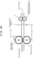
- Fig. 6 shows schematic views showing an example of the positional relationship between the leading edge of a fed document and a feed roller pair according to the first embodiment.
- Fig. 6(a) shows a state in which the document leading edge has reached a nip portion formed between the feed roller 6 and the separation roller 7.
- Fig. 6(b) shows a state in which the document leading edge has passed through the nip portion formed between the feed roller 6 and the separation roller 7.
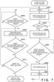
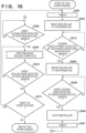
- Fig. 7 is a flowchart for explaining an example of a feeding control operation in the thin paper mode, which is performed by the control unit 45 according to the first embodiment.
- This control aims at preventing the leading edge of a sheet from being caught by the feed roller 6 when thin paper with low stiffness has reached the feed roller 6.
- the processing shown in this flowchart is implemented when the CPU (not shown) of the control unit 45 executes a program stored in the ROM. Note that the control shown in Fig. 7 and the control shown in Fig. 3 described above are performed in one feeding operation.
- the control unit 45 drives the conveyance rollers when the feeding operation in the thin paper mode is started.
- the conveyance rollers are controlled to be continuously driven from then on.
- the control unit 45 drives the feed roller 6 at a first feeding speed V3 (low speed) at which the sheet is not caught by the feed roller 6 (step S202).
- the control unit 45 continuously drives the feed roller 6 at the first feeding speed V3 during the time after the leading edge of the sheet is fed from the sheet stacker 1 until a predetermined time T3 in which the leading edge passes through the nip portion formed between the feed roller 6 and the separation roller 7 elapses (TIME ⁇ T3).
- the control unit 45 waits for the elapse of the predetermined time T3 (step S203).
- the control unit 45 Upon determining that the predetermined time T3 has elapsed (YES in step S203), the control unit 45 judges that the leading edge of the sheet has passed through the nip portion formed between the feed roller 6 and the separation roller 7, and drives the feed roller 6 by switching the feeding speed to a second feeding speed V4 (high speed) (step S204).
- the second feeding speed V4 (high speed) is higher than the first feeding speed V3 (low speed).
- the second feeding speed V4 is, for example, a speed equal to the conveyance speed to drive the registration rollers 17, 18, 20, and 21 or almost the same speed approximate to the conveyance speed.
- control unit 45 monitors whether it is detected that the sheet leading edge has reached the middle-registration sensor 33 (step S205). Upon determining that it is not detected that the sheet leading edge has reached the middle-registration sensor 33 (NO in step S205), the control unit 45 continues monitoring in step S205. Upon determining that it is detected that the sheet leading edge has reached the middle-registration sensor 33 (YES in step S205), the control unit 45 advances the process to step S206.
- the control unit 45 stops driving feed motor 8 (step S206), returns the count TIME for driving control of the feed roller 6 to "0", and stops measuring time (step S207).
- control unit 45 monitors whether it is detected that the sheet leading edge has reached the post-registration sensor 34 (step S208). If the post-registration sensor 34 does not detect that the sheet leading edge has reached (NO in step S208), the control unit 45 continues monitoring in step S208.
- control unit 45 starts the image reading operation by the image reading sensors 14 and 15 at a predetermined timing (step S209).
- control unit 45 monitors whether the sheet trailing edge has reached the post-registration sensor 34 (step S210). If the post-registration sensor 34 does not detect the reaching of the sheet trailing edge (NO in step S210), the control unit 45 continues the image reading operation in step S209.
- step S210 If the post-registration sensor 34 detects the reaching of the sheet trailing edge (YES in step S210), the control unit 45 advances the process to step S211.
- step S211 the control unit 45 checks whether a sheet exists on the sheet stacker 1. Upon determining that a sheet exists on the sheet stacker 1 (YES in step S211), that is, if the next sheet exists, the control unit 45 returns the process to step S201.
- control unit 45 ends the processing of the flowchart.
- the feed roller 6 when resuming driving of the feed roller 6 after the reaching of the trailing edge of the sheet is detected by the post-registration sensor 34, the feed roller 6 is controlled to the first feeding speed. Furthermore, upon determining that the leading edge of the sheet has passed through the nip between the feed roller 6 and the separation roller 7, the feed roller 6 is controlled to the second feeding speed higher than the first feeding speed. With this control, even if the sheet to be fed is thin paper or the like with low stiffness, jam in which, for example, a sheet is caught by the feed roller in feeding can be made less likely to occur.
- step S210 instead of detecting the reaching of the sheet trailing edge by the post-registration sensor 34, when the middle-registration sensor 33 or the pre-registration sensor 32 detects the reaching of the sheet trailing edge, the process may advance to step S211. In these cases, the sheet interval can be made small as compared to a case in which the reaching of the sheet trailing edge is detected by the post-registration sensor 34.
- step S205 if the post-registration sensor 34 detects the sheet leading edge, the process advances to step S206, and the process of step S208 is omitted.
- a method of deciding the time (T3) to drive the feed motor 8 such that the feed roller 6 is driven at the first feeding speed V3 (low speed) will be described below with reference to Fig. 8 .
- Fig. 8 is a view for explaining the relationship between sheets (documents) on the sheet stacker 1, the feed roller 6, the positions of the leading edge portions of the documents, and the feeding speed of the pickup roller 4.
- the length X of the leading edge portion of the document may be, for example, about 1/4 of the peripheral diameter of the feed roller 6. Note that the position of the nip portion between the feed roller 6 and the separation roller 7 is set here as the center position of the shaft of the feed roller 6.
- the first feeding speed V3 (low speed) is, for example, a set speed at which the peripheral speed of the feed roller 6 becomes almost the second feeding speed V4 (high speed) even if an overshoot occurs at the rising of the feed motor 8 that rotationally drives the feed roller 6.
- the set speed is obtained in advance by experiments and the like.
- the first feeding speed V3 and the feeding speed V5 by the pickup roller 4 may be set equal.
- control unit 45 controls the feed roller 6 to the second feeding speed V4 (high speed) at the start of driving of the feed roller 6.
- a plurality of stacked documents may simultaneously be fed due to friction between the documents and passed through the pickup roller 4, resulting in a so-called "fed-together" state in which a document scheduled to be fed next already exists at a position close to the nip portion between the feed roller 6 and the separation roller 7.
- the speed change is executed with the predetermined time T3, as described above, the leading edge portion of the document immediately passes through the nip portion between the feed roller 6 and the separation roller 7. That is, in this case, even if the leading edge portion of the document passes through the nip portion, and the speed can be switched to the speed V4, feeding may be continued at the speed V3 until the predetermined time T3 elapses, and throughput may lower.
- Fig. 9 shows views showing a configuration in which a thin paper conveyance registration sensor 65 (second sheet detection sensor) that is an optical sensor for the thin paper mode is arranged at a position parallel to the feed roller 6 in the conveyance direction of the document.
- a thin paper conveyance registration sensor 65 second sheet detection sensor
- Fig. 9(a) shows a state in which the document leading edge has reached the nip portion formed between the feed roller 6 and the separation roller 7.
- Fig. 9(b) shows a state in which the document leading edge has passed through the nip portion formed between the feed roller 6 and the separation roller 7 and reached the thin paper conveyance registration sensor 65.
- FIG. 10 A feeding control operation according to this aspect is shown in Fig. 10 .
- Fig. 10 is a flowchart for explaining an example of a feeding control operation in the thin paper mode, which is performed by the control unit 45 in the other aspect of the first embodiment.
- the processing shown in this flowchart is implemented when the CPU (not shown) of the control unit 45 executes a program stored in the ROM.
- the same step numbers as in Fig. 7 denote the same steps.
- the control shown in Fig. 10 and the control shown in Fig. 3 described above are performed in one feeding operation.
- the control unit 45 drives the feed roller 6 at the first feeding speed V3 (low speed) (step S202), and then advances the process to step S212.
- step S212 the control unit 45 monitors whether the thin paper conveyance registration sensor 65 detects the leading edge of the document. Upon determining that the thin paper conveyance registration sensor 65 has not detected the leading edge of the document yet (NO in step S212), the control unit 45 continues monitoring in step S212.
- step S212 upon determining that the thin paper conveyance registration sensor 65 has detected the leading edge of the document (YES in step S212), the control unit 45 advances the process to step S204. Processing from step S204 is the same as in Fig. 7 , and a description thereof will be omitted.
- the control unit 45 Based on the detection of the leading edge of the document by the thin paper conveyance registration sensor 65, the control unit 45 changes the driving speed of the feed roller 6 from the first feeding speed V3 to the second feeding speed V4. With this configuration, speed control for thin paper conveyance can more effectively be executed.
- the detection position of the optical sensor is preferably located on the downstream side of the position of the nip portion formed by the feed roller 6 and the separation roller 7.
- the thin paper conveyance registration sensor 65 may be a detection sensor other than an optical sensor.
- a tracking sensor movement detection sensor
- the same effect as described above can be obtained.
- step S212 the driving speed of the feed roller 6 may be changed from V3 to V4 in accordance with not the detection of the document leading edge by the thin paper conveyance registration sensor 65 but the detection of the document leading edge by the pre-registration sensor 32.
- the driving speed of the feed roller 6 may be changed from V3 to V4 in accordance with not the detection of the document leading edge by the thin paper conveyance registration sensor 65 but the detection of the document by the multiple feed detection sensor 30.
- the feeding speed may be switched when a document is detected by the skew sensors.
- the feeding speed may be switched when a document is detected by one of the sensors provided on the downstream side of the separation roller pair 42.
- sensors As for the type of sensors, sensors of any detection type can be used.
- control unit 45 may change the driving speed of the feed roller 6 from the V3 to V4 at an earlier timing of the timing from the detection of the trailing edge of the preceding sheet by the post-registration sensor 34 to the elapse of T3 and the timing of the detection of the subsequent sheet by the thin paper conveyance registration sensor 65.
- driving of a feed roller 6 (separation roller 7) is turned on/off will be described.
- driving of a registration roller pair (17 and 18) may be turned on/off at the timing of turning on/off driving of the feed roller 6 (separation roller 7). Even concerning a case in which driving of the feed roller 6 and the separation roller 7 is turned on/off, this will be referred to as “driving of the feed roller 6 is turned on/off" hereinafter.
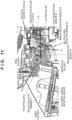
- Fig. 11 is a partial sectional view schematically showing a part of the configuration of a sheet conveyance apparatus (image reading apparatus) to which a sheet feeder according to the second embodiment of the present invention can be applied. Note that the same reference numerals as in Fig. 1 and the like denote the same components.
- a registration roller pair (20 and 21) is disposed on the downstream side of a registration roller pair (17 and 18).
- a middle-registration sensor 33 (third sheet detection sensor) is disposed on the downstream side of the registration roller pair (17 and 18) and on the upstream side of the registration roller pair (20 and 21), and detects a conveyed sheet.
- a post-registration sensor 34 is disposed on the downstream side of the conveyance path (20 and 21) and on the upstream side of image reading sensors 14 and 15, and detects a conveyed sheet.
- Fig. 12 is a timing chart showing an example of the relationship between the operations of a pickup roller, a feed roller (and the registration roller pairs) and the detection states of a pre-registration sensor and the middle-registration sensor according to the second embodiment.
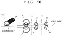
- Figs. 13 to 16 are schematic views showing an example of the relationship between the operations of the pickup roller, the feed roller, and the registration roller pairs and the detection states of the pre-registration sensor and the middle-registration sensor according to the second embodiment. Note that the same reference numerals as in (0) to (11) of Fig. 12 denote the same states. A series of procedures will be described below.
- the feed roller 6 and the registration rollers (17, 18, 20, and 21) are driven ((0) of Fig. 13 ), and a pickup roller 4 is moved to the contact position ((1) of Fig. 13 ) and rotated after the elapse of a specific time (TD) ((2) of Fig. 13 ), thereby feeding a sheet to the feed roller 6.
- TD specific time
- the pickup roller 4 is moved to the retreat position ((4) of Fig. 14 ), and the rotation is stopped ((4)' of Fig. 14 ).
- the feed roller 6 is stopped ((6) of Fig. 14 ).
- the sheet trailing edge passes through the pre-registration sensor 32 ((7) of Fig. 15 ) (the time is defined as "t0"), and after the elapse of t1 ((8) of Fig. 15 ), the feed roller 6 is rotated. After that, the sheet trailing edge passes through the middle-registration sensor 33 ((8)' of Fig. 15 ).
- the pickup roller 4 is moved to the contact position ((10) of Fig. 15 ) and rotated after the elapse of the specific time (TD) ((11) of Fig. 16 ), thereby feeding the next sheet to the feed roller 6.
- the above-described time t2 is preferably "t2 > t1 + L/V1".
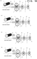
- Figs. 17 to 19 are schematic views showing an example of the relationship between the operations of the pickup roller, the feed roller, and the registration roller pairs and the detection states of the pre-registration sensor and the middle-registration sensor according to the second embodiment. These drawings correspond to a case in which the leading edge of the next sheet is detected by the pre-registration sensor 32 before the elapse of t2.
- the feed roller 6 and the registration rollers (17, 18, 20, and 21) are driven ((0) of Fig. 17 ), and the pickup roller 4 is moved to the contact position ((1) of Fig. 17 ) and rotated after the elapse of the specific time (TD) ((2) of Fig. 17 ), thereby feeding the first sheet to the feed roller 6.
- the pickup roller 4 is moved to the retreat position ((4) of Fig. 18 ), and the rotation is stopped ((4)' of Fig. 18 ).
- this example corresponds to a case in which at the point of time of (4), the second sheet is fed together with the first sheet due to a friction or static electricity between the sheets, and reaches the nip portion of the feed roller 6, as shown in Fig. 18 .
- the first sheet and the second sheet are separated by the separation roller 7 so multiple feed does not occur.
- the feed roller 6 is stopped ((6) of Fig. 18 ).
- the trailing edge of the first sheet passes through the pre-registration sensor 32 ((7) of Fig. 19 ) (the time is defined as "t0"), and after the elapse of t1 ((8) of Fig.
- the time t2 after the sheet trailing edge passes through the pre-registration sensor 32 until the movement of the pickup roller 4 to the contact position starts can be set to t2', for example, "t2' > (L - V1 ⁇ (L/V2))/V1". That is, the time can be made slightly shorter than "t2 > t1 + L/V1" in the above-described case in which the feed roller 6 is stopped.
- Fig. 20 is a view for explaining the relationship between the positions of the feed roller 6, the pre-registration sensor 32, and the registration rollers 17 and 18, the feeding speed of the feed roller 6, and the conveyance speed of the registration rollers.
- the minimum condition of the wait time until the pickup roller 4 is lowered to the subsequent sheet is as follows.
- the second sheet reaches the feed roller 6 together with the feeding of the first sheet, the second sheet exists at a position ahead of the position of the feed roller 6 by "V1 ⁇ (L/V2)" at the point of time when the first sheet passes through the pre-registration sensor 32.
- the process waits for only the time "(L - V1 ⁇ (L/V2))/V1" in which the second sheet is fed from that position to the position of the pre-registration sensor 32 at the feeding speed V1, the above-described second sheet should reach the pre-registration sensor 32.
- the time "(L - V1 ⁇ (L/V2))/V1" can be set as the minimum condition of the wait time until the pickup roller 4 is lowered to the subsequent sheet.
- control is performed to stop the feed motor 8 when the leading edge of the sheet reaches the middle-registration sensor 33.
- the present invention can also be applied even to a sheet feeder having a configuration in which, for example, a pickup roller arranged below a sheet stacker comes, from the lower side, into contact with a sheet stacked on the sheet stacker with a tilt, and supplies sheets sequentially from the lower side of the sheet bundle to a feed roller.
Landscapes
- Engineering & Computer Science (AREA)
- Physics & Mathematics (AREA)
- General Physics & Mathematics (AREA)
- Mechanical Engineering (AREA)
- Microelectronics & Electronic Packaging (AREA)
- Sheets, Magazines, And Separation Thereof (AREA)
- Controlling Sheets Or Webs (AREA)
Description
- The present invention relates to a feed technique for a document sensitive to a load, for example, thin paper, a slip, old paper (history book), an already wrinkled document, an already folded document, or a broken document in a sheet feeder capable of feeding a sheet.
- In a conventional sheet feeder, when continuously feeding a plurality of sheets, every time one sheet is fed, an operation of moving a pickup roller (for example, 4 in
Fig. 1 to be described later) to a sheet take-in position, bringing it into contact with the sheet, and rotating it, and then moving it to a retreat position is repeated. However, if the sheet is thin paper or the like with low stiffness, jam may occur between a separation roller pair (for example, 6 and 7 inFig. 1 ) and the pickup roller. - As a jam measure for a sheet such as thin paper,
JP H06 9110 A JP H06 9110 A Fig. 1 to be described later) detects the trailing edge of a precedingly fed sheet. After that, if the pre-registration sensor does not detect the leading edge of the next sheet after the elapse of a specific time, the pickup roller is brought into contact with the sheet and rotated. There has been proposed a technique of feeding a sheet while minimizing use of the pickup roller in this way. - In
JP H10 250862 A claim 1 and a control method of a sheet feeder as specified in the preamble ofclaim 8. - The technique of
JP H06 9110 A - As described above, in the conventional technique, if a sheet to be fed is thin paper or the like with low stiffness, jam may occur on the feed roller.
- The present invention has been made to solve the above-described problem. It is an object of the present invention to provide a mechanism capable of making jam less likely to occur in feeding even if a sheet to be fed is thin paper or the like with low stiffness.
- The present invention has been made in consideration of the above-described problem, and provides a sheet feeder as specified in
claim 1 and a control method of a sheet feeder as specified inclaim 8. - According to the present invention, it is possible to make jam less likely to occur in feeding even if a sheet to be fed is thin paper or the like with low stiffness.
-
-
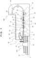
Fig. 1 is a partial sectional view of a sheet conveyance apparatus including a sheet feeder according to the first embodiment; -
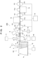
Fig. 2 is a view schematically showing the configuration of the main part of the sheet conveyance apparatus; -
Fig. 3 is a flowchart showing a control operation in a thin paper mode according to the first embodiment; -
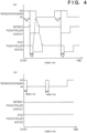
Fig. 4 shows timing charts showing examples of the operations of a pre-registration sensor and a pickup roller according to the first embodiment; -
Fig. 5 is a graph showing a change in a contact pressure to a sheet after the pickup roller is brought into contact with the sheet; -
Fig. 6 shows schematic views showing an example of the positional relationship between the leading edge of a fed document and a feed roller pair according to the first embodiment; -
Fig. 7 is a flowchart for explaining the control operation of the feed roller in the thin paper mode according to the first embodiment; -
Fig. 8 is a view for explaining the relationship between sheets on a sheet stacker, the feed roller, the positions of the leading edge portions of documents, and the feeding speed of the pickup roller according to the first embodiment; -
Fig. 9 shows views for explaining the positional relationship between the feed roller and an optical sensor for the thin paper mode according to another aspect of the first embodiment; -
Fig. 10 is a flowchart for explaining the control operation of the feed roller in the thin paper mode according to another aspect of the first embodiment; -
Fig. 11 is a partial sectional view schematically showing a part of the configuration of a sheet conveyance apparatus to which a sheet feeder according to the second embodiment can be applied; -
Fig. 12 is a timing chart showing an example of the relationship between the operations of a pickup roller, a feed roller, and registration roller pairs and the detection states of a pre-registration sensor and a middle-registration sensor according to the second embodiment; -
Fig. 13 shows schematic views showing an example of the relationship between the operations of the pickup roller, the feed roller, and the registration roller pairs and the detection states of the pre-registration sensor and the middle-registration sensor according to the second embodiment; -
Fig. 14 shows schematic views showing an example of the relationship between the operations of the pickup roller, the feed roller, and the registration roller pairs and the detection states of the pre-registration sensor and the middle-registration sensor according to the second embodiment; -
Fig. 15 shows schematic views showing an example of the relationship between the operations of the pickup roller, the feed roller, and the registration roller pairs and the detection states of the pre-registration sensor and the middle-registration sensor according to the second embodiment; -
Fig. 16 is a schematic view showing an example of the relationship between the operations of the pickup roller, the feed roller, and the registration roller pairs and the detection states of the pre-registration sensor and the middle-registration sensor according to the second embodiment; -
Fig. 17 shows schematic views showing an example of the relationship between the operations of the pickup roller, the feed roller, and the registration roller pairs and the detection states of the pre-registration sensor and the middle-registration sensor according to the second embodiment; -
Fig. 18 shows schematic views showing an example of the relationship between the operations of the pickup roller, the feed roller, and the registration roller pairs and the detection states of the pre-registration sensor and the middle-registration sensor according to the second embodiment; -
Fig. 19 shows schematic views showing an example of the relationship between the operations of the pickup roller, the feed roller, and the registration roller pairs and the detection states of the pre-registration sensor and the middle-registration sensor according to the second embodiment; and -
Fig. 20 is a view for explaining the relationship between the positions of the feed roller, the pre-registration sensor, and the registration rollers, the feeding speed of the feed roller, and the conveyance speed of the registration rollers. - A sheet conveyance apparatus including a sheet feeder according to the first embodiment of the present invention will be described first.
-
Fig. 1 is a partial sectional view schematically showing the configuration of a sheet conveyance apparatus (image reading apparatus) including a sheet feeder according to the first embodiment of the present invention. -
Fig. 2 is a view schematically showing the configuration of the main part of the sheet conveyance apparatus shown inFig. 1 . - A case in which the sheet conveyance apparatus according to the present invention is applied to an image reading apparatus will be described here as an example. However, the sheet conveyance apparatus can also be applied to various kinds of sheet conveyance apparatuses such as an apparatus including a document conveyance system, such as a printing apparatus (printer or the like) for printing on a sheet and a multi-function peripheral that combines an image reading apparatus and a printing apparatus.
- As shown in
Figs. 1 and2 , asheet conveyance apparatus 200 according to this embodiment includes a sheet take-in device (sheet feeder) 101. - A plurality of sheets are stacked on a sheet stacker (sheet placement table) 1, and the
sheet stacker 1 is configured to move up and down. A sheetstacker drive motor 2 moves thesheet stacker 1 up and down. Asheet detection sensor 3 detects that a sheet stacked on thesheet stacker 1 is located at a sheet take-in position. A sheetstacking detection sensor 12 detects that a sheet is stacked on asheet stacking surface 1a of thesheet stacker 1. A documentjumping detection sensor 35 includes a plurality of sensors arranged in a direction orthogonal to thesheet stacking surface 1a, and detects jumping of a sheet stacked on thesheet stacker 1. For example, the documentjumping detection sensor 35 can detect jumping of a document, which occurs when, for example, a stapled document is stacked on thesheet stacker 1 and fed. This enables control of, for example, stopping feeding of the stapled document. - A pickup roller 4 (take-in means) as an example of a sheet pickup unit feeds a sheet on the
sheet stacker 1 from thesheet stacker 1. A pickuproller drive motor 5 rotates thepickup roller 4 in a direction (take-in direction) of taking in the sheet. The state shown inFig. 2 is a state in which the sheet upper surface is located at the sheet take-in position, and the take-in of the sheet starts when thepickup roller 4 is rotated. In addition, thepickup roller 4 can be driven and moved by a driving unit (not shown) to the sheet take-in position shown inFig. 2 and a retreat position (not shown) on the upper side of the sheet take-in position. Thepickup roller 4 is moved to the sheet take-in position when taking a sheet in, and moved to the retreat position when the take-in is ended. In the example shown inFig. 1 , thepickup roller 4 pivots about arotation center 64 of the pickup roller, which is provided on the downstream side of thepickup roller 4 int the conveyance direction. Hence, when thepickup roller 4 comes into contact with the sheet, the sheet can readily be pushed in the conveyance direction. - A rotation instruction of the
pickup roller 4 and a moving instruction to the sheet take-in position or the retreat position are issued by acontrol unit 45. Thecontrol unit 45 includes a CPU, a ROM, a RAM, and the like (none are shown). The CPU executes programs stored in the ROM, thereby implementing various kinds of control. Additionally, thepickup roller 4 carries an auxiliary role to reliably perform separation/feeding by aseparation roller pair 42 to be described later. When a sheet on thesheet stacker 1 is fed by thepickup roller 4 to the nip portion of theseparation roller pair 42, separation/feeding by theseparation roller pair 42 can reliably be performed. - In the
separation roller pair 42, afeed roller 6 is driven by afeed motor 8 to rotate in a direction (feeding direction) of feeding the sheet to the downstream side in the conveyance direction. Aseparation roller 7 always receives a rotating force of rotating in a direction of pushing back the sheet to the upstream side in the conveyance direction from aseparation motor 9 via a torque limiter (slip clutch) (not shown). - When one sheet exists between the
feed roller 6 and theseparation roller 7, the rotating force in a direction of feeding the sheet to the downstream side by the frictional force between theseparation roller 7 and the sheet fed to the downstream side by thefeed roller 6 is larger than the upper limit value of the rotating force transmitted by the above-described torque limiter in the direction in which theseparation roller 7 pushes back the sheet to the upstream side. For this reason, theseparation roller 7 rotates following the feed roller 6 (rotates together). - On the other hand, if a plurality of sheets exist between the
feed roller 6 and theseparation roller 7, theseparation roller 7 receives, from the roller shaft, rotation in the direction of pushing back the sheets to the upstream side, thereby preventing sheets other than the sheet at the uppermost position from being conveyed to the downstream side. - In this way, by the function of the
feed roller 6 to feed a sheet to the downstream side and the function of theseparation roller 7 to prevent a sheet from being conveyed to the downstream side, even if sheets are fed in an overlapping state to the nip portion (the contact portion between thefeed roller 6 and the separation roller 7) formed between thefeed roller 6 and theseparation roller 7, only the sheet at the uppermost position is fed to the downstream side, and the remaining sheets are not conveyed to the downstream side. Hence, the sheets in the overlapping state are separated and fed. - The
feed roller 6 and theseparation roller 7 form a pair of separation roller pairs 42 (sheet separation portion). Note that in this embodiment, theseparation roller pair 42 is used. Instead of theseparation roller pair 42, a separation belt/roller pair formed by changing one of the separation roller and the feed roller to a belt may be used. Alternatively, the separation roller may be replaced with a separation pad, and the pad may be brought into contact with a sheet to prevent a plurality of sheets from being conveyed to the downstream side. Instead of rotating theseparation roller 7, it may be used in contact with the sheet, like a separation pad. - By the sheet pickup unit formed by the thus configured
pickup roller 4, feedroller 6,separation roller 7, and the like, the sheets stacked on thesheet stacker 1 are separated one by one and taken into thesheet conveyance apparatus 200. - In addition, when a multiple
feed detection sensor 30 is provided at a position where the separated sheet passes (that is, on the downstream side of the separation roller pair 42), it can be detected whether the sheets are separated one by one by the sheet separation portion. In this embodiment, a detection device using ultrasonic wave transmitting and receiving portions is used as the multiplefeed detection sensor 30, and multiple feed can be detected based on the attenuation amount of an ultrasonic wave between the transmitting and receiving portions across the conveyance path. Note that the multiplefeed detection sensor 30 can also be used as a sensor configured to detect a sheet that has reached a predetermined position (a position corresponding to between the ultrasonic wave transmitting and receiving portions) of the conveyance path. - A
conveyance motor 10 drives other rollers (sheet conveyance unit) to convey the separated sheet to an image reading position where the image of the sheet is read byimage reading sensors conveyance motor 10 drives the rollers to change the sheet conveyance speed in accordance with a speed optimum for sheet reading and settings such as the resolution of the sheet. - A nip
gap adjusting motor 11 adjusts the gap between thefeed roller 6 and theseparation roller 7 or a contact force (nip pressure) of thefeed roller 6 contacting theseparation roller 7 via a sheet. This can adjust the gap adapted for the thickness of the sheet or the contact force and separate the sheet. - A
registration clutch 19 transmits the rotation driving force of theconveyance motor 10 to a registration roller 18 (sheet conveyance unit) or blocks the transmission. By stopping the rotation of a first registration roller pair formed by theregistration rollers - A second registration roller pair formed by
registration rollers conveyance rollers conveyance rollers discharge rollers discharge stacking unit 44. Adischarge sensor 16 detects the passing of the conveyed sheet. After thedischarge sensor 16 detects the trailing edge of the sheet, a discharge brake for reducing the rotation speed of the discharge roller pair (26 and 27) is applied, thereby preventing the discharged sheet from popping out and improving the discharge alignment property. Two guide plates including anupper guide plate 40 and alower guide plate 41 guide the sheet conveyed by the separation roller pair, the registration roller pairs, the conveyance roller pairs, and the discharge roller pair. - Apre-registration sensor 32 (fourth sheet detection sensor) is arranged on the upstream side of the registration roller pair (17 and 18), and detects the fed sheet. A post-registration sensor 34 (first sheet detection sensor) is arranged on the downstream side of the registration roller pair (20 and 21), and detects the conveyed sheet. Furthermore, a middle-registration sensor 33 (third sheet detection sensor) is arranged on the downstream side of the registration roller pair (17 and 18) and on the upstream side of the registration roller pair (20 and 21), and detects the conveyed sheet.
- When the
post-registration sensor 34 detects the sheet, thecontrol unit 45 issues an image reading instruction to theimage reading sensors reference numerals image reading sensors - An example of the control operation of the
pickup roller 4 at the time of execution of a thin paper mode (predetermined specific mode), which is performed by thecontrol unit 45 according to the first embodiment will be described next with reference toFig. 3 . -
Fig. 3 is a flowchart for explaining an example of the control operation in the thin paper mode (to be also referred to as a "thin paper conveyance mode" hereinafter), which is performed by thecontrol unit 45 according to the first embodiment. That is, the processing shown in this flowchart is implemented when the CPU (not shown) of thecontrol unit 45 executes a program stored in the ROM. Note that the thin paper mode can be set from an operation unit (not shown) or an information processing apparatus (personal computer or the like) communicably connected to thesheet conveyance apparatus 200. - When a feeding operation in the thin paper mode is started, the
control unit 45 drives thefeed roller 6 and starts measuring time (measurement time (TIME) = 0) (step S101). - Next, in step S102, the
control unit 45 checks thepre-registration sensor 32 and determines whether thepre-registration sensor 32 detects a sheet leading edge. - Upon determining that the
pre-registration sensor 32 does not detect a sheet leading edge (NO in step S102), thecontrol unit 45 advances the process to step S103. - In step S103, the
control unit 45 determines whether the measurement time (TIME) has exceeded a specific time (TS). Upon determining that the measurement time (TIME) has not exceeded the specific time (TS) (NO in step S103), thecontrol unit 45 returns the process to step S102. - On the other hand, upon determining that the measurement time (TIME) has exceeded the specific time (TS) (YES in step S103), that is, if a sheet leading edge is not detected by the
pre-registration sensor 32 even if the measurement time (TIME) has reached the specific time (TS), thecontrol unit 45 advances the process to step S104. - In step S104, the
control unit 45 moves thepickup roller 4 to the sheet take-in position and brings the pickup roller into contact with the sheet. - Further, in step S105, the
control unit 45 rotates thepickup roller 4 after the elapse of a specific time (TD) to be described later. Hence, thepickup roller 4 feeds the sheet to thefeed roller 6. - Next, in step S106, the
control unit 45 starts measuring time again (measurement time (TIME) = 0). - In step S107, the
control unit 45 checks thepre-registration sensor 32 and determines whether a sheet leading edge is detected by thepre-registration sensor 32. - Upon determining that the
pre-registration sensor 32 does not detect a sheet leading edge (NO in step S107), thecontrol unit 45 advances the process to step S110. - In
step S 110, thecontrol unit 45 determines whether the measurement time (TIME) has exceeded an error time (TOUT). Upon determining that the measurement time (TIME) has not exceeded the error time (TOUT) (NO in step S110), thecontrol unit 45 returns the process to step S107. - On the other hand, upon determining that the measurement time (TIME) has exceeded the error time (TOUT) (YES in step S110), that is, if a sheet leading edge is not detected by the
pre-registration sensor 32 even if the measurement time (TIME) has reached the error time (TOUT), thecontrol unit 45 advances the process to step S111. That is, it is determined that although thepickup roller 4 is moved to the take-in position and rotated, a sheet leading edge is not detected even if reaching the error time, that is, a sheet feeding error has occurred (for example, jam has occurred). - The
control unit 45 moves thepickup roller 4 to the retreat position (step 5111), stops the rotation of the pickup roller 4 (step 5112), and error-ends the processing of the flowchart. - On the other hand, upon determining in step S107 that the
pre-registration sensor 32 detects a sheet leading edge (YES in step S107), thecontrol unit 45 advances the process to step S108. - The
control unit 45 moves thepickup roller 4 to the retreat position (step S108), stops the rotation of the pickup roller 4 (step S109), and advances to step S113. - In addition, upon determining in step S102 that the
pre-registration sensor 32 detects a sheet leading edge (YES in step S102), thecontrol unit 45 advances to step S113. In this case, thepickup roller 4 does not move to the contact position and remains at the retreat position. That is, in this situation, a sheet leading edge reaches thepre-registration sensor 32 even if thepickup roller 4 is not driven. This situation is a situation in which after a sheet has reached thefeed roller 6 due to a friction or static electricity generated between the sheet and a precedingly fed sheet, the previously fed sheet passes through thefeed roller 6, is conveyed by thefeed roller 6, and reaches at least a point before thepre-registration sensor 32. At this time, feed by thepickup roller 4 is unnecessary. To prevent damage caused by bringing thepickup roller 4 into contact with the sheet, thepickup roller 4 is kept at the retreat position. - Upon determining, in step S102 or S107, that the leading edge of a sheet is detected by the
pre-registration sensor 32, thecontrol unit 45 advances the process to step S113. In step S113, thecontrol unit 45 issues an image reading instruction to theimage reading sensors post-registration sensor 34, and causes theimage reading sensors control unit 45 monitors sheet trailing edge detection by the pre-registration sensor 32 (step S114). Upon determining that thepre-registration sensor 32 does not detect the sheet trailing edge (NO in step S114), thecontrol unit 45 returns the process to step S113. - On the other hand, upon determining that the
pre-registration sensor 32 detects the sheet trailing edge (YES in step S114), thecontrol unit 45 advances the process to step S115. Note that thecontrol unit 45 ends the reading operation in step S113 at a predetermined timing after thepost-registration sensor 34 detects the leading edge of the sheet. - In step S115, the
control unit 45 checks whether a sheet exists on thesheet stacker 1. Upon determining that a sheet exists on the sheet stacker 1 (YES in step S115), that is, if a next sheet exists, thecontrol unit 45 returns the process to step S101. - On the other hand, upon determining that no sheet exists on the sheet stacker 1 (NO in step S115), that is, if a next sheet does not exist, the
control unit 45 ends the processing of the flowchart. Note that it is preferable that before the end, if a sheet is detected by thepre-registration sensor 32 after waiting for a time equal to or more than the specific time (TS), the process advances to step S113, and if no sheet is detected, the processing is ended. -
Fig. 4 shows timing charts showing examples of the operations of thepre-registration sensor 32 and thepickup roller 4 according to the first embodiment. -
Fig. 4(a) corresponds to an example in a case in which thepre-registration sensor 32 does not detect the leading edge of a sheet even if the measurement time (TIME) has exceeded the specific time (TS) (TIME > TS). In this case, thepickup roller 4 moves to the contact position, and after the specific time (TD), rotates to feed the sheet to thefeed roller 6. This prevents the occurrence of jam caused by the contact pressure of thepickup roller 4. -
Fig. 4(b) corresponds to an example in a case in which thepre-registration sensor 32 detects the leading edge of a sheet when the measurement time (TIME) is within the specific time (TS) (TIME < TS). In this case, thepickup roller 4 does not move to the contact position and remains at the retreat position. For this reason, jam caused by the contact pressure of thepickup roller 4 does not occur. Note that inFig. 4(b) , the output of thepre-registration sensor 32 before counting of the measurement time (TIME) starts is OFF. This indicates that before counting of the measurement time (TIME) starts, thepre-registration sensor 32 itself is not driven, and the output is OFF. On the other hand, if thepre-registration sensor 32 is always driven, the next sheet may reach thepre-registration sensor 32 before counting of the measurement time (TIME) starts, and the output of thepre-registration sensor 32 is assumed to be ON. In this case, this may be confirmed before the start of counting of the measurement time (TIME), and it may be determined as YES in step S 102 ofFig. 3 . Note that thepre-registration sensor 32 detects a sheet by receiving, by a light receiving portion, irradiation light that is output from a light source arranged on one side (as an example, the lower guide plate 41) of the conveyance path and returned to the one side again by a light guide member arranged on the facing other side (as an example, the upper guide plate 40). Hence, if a sheet exists at the sensor position, the irradiation light is shielded. Hence, the light receiving level in the light receiving portion is L level. In this embodiment, the output becomes ON when the light receiving level is L level. On the other hand, if no sheet exists at the sensor position, the irradiation light returns without being shielded. Hence, the light receiving level in the light receiving portion is H level. In this embodiment, the output becomes OFF when the light receiving level is H level. This also applies to other sensors in this embodiment. - Note that in this embodiment, the specific time (TS) is set to, for example, 1 sec in consideration of shortening of the feed time in
Fig. 4(a) and reliability of sheet detection inFig. 4(b) . However, the specific time (TS) is not limited to 1 sec. -
Fig. 5 is a graph showing a change in a contact pressure to a sheet after thepickup roller 4 is brought into contact with the sheet. - As shown in
Fig. 5 , until a time TC elapses from the start of contact of thepickup roller 4 to the sheet, the contact pressure of thepickup roller 4 to the sheet changes. When the contact pressure is high, the frictional force between sheets also increases. Hence, if the rotation of thepickup roller 4 is started before the elapse of the time TC, a sheet is readily conveyed together, and feed jam readily occurs. - On the other hand, in this embodiment, as the specific time (TD) after the pickup roller is brought into contact with the sheet until the pickup roller is rotated, a time longer than the contact pressure change time (TC) shown in
Fig. 5 is set, and rotation is started. The time is set to, for example, 0.2 sec. However, the specific time (TD) is not limited to 0.2 sec. - Note that in steps S108 and S109 or steps S111 and S112 in
Fig. 3 and inFig. 4 , control is done to move thepickup roller 4 to the retreat position and then stop rotation. However, the retreat operation and the rotation stop may be simultaneously performed. The order may be changed to stop rotation and then perform the retreat operation. However, during the time from the stop of rotation to the retreat, the frictional force between sheets is increased by the pressing pressure of thepickup roller 4, and a sheet is readily conveyed together. Hence, the jam preventing effect becomes high when rotation is stopped after the retreat position, or the retreat and the rotation stop are simultaneously performed. - As described above, the first embodiment is characterized in that if the pre-registration sensor does not detect the leading edge of a next sheet after the elapse of the standby time (TS) after detecting the trailing edge of a previously separated and fed sheet, the pickup roller is moved to a position to contact a sheet stacked on the sheet stacker, after the elapse of TD, the pickup roller is rotated, and after the pre-registration sensor detects the leading edge of the sheet, the pickup roller is retreated to a position not to contact a sheet, and rotation is stopped. With this configuration, as a jam measure for a sheet such as thin paper, the timings of sheet contact and rotation start of the pickup roller are controlled, and a further jam measure is applied, thereby making jam less likely to occur in feeding even if the sheet to be fed is thin paper or the like with low stiffness.
- Note that the movement and rotation of the
pickup roller 4 may be controlled using the middle-registration sensor 33 in place of thepre-registration sensor 32. That is, if the leading edge of the next sheet is not detected even after the elapse of the standby time (TS) after the middle-registration sensor 33 detects the trailing edge of the previously separated and fed sheet, thepickup roller 4 may be moved to the position to contact a sheet stacked on the sheet stacker, after the elapse of TD, thepickup roller 4 may be rotated, and after the middle-registration sensor 33 detects the leading edge of the sheet, thepickup roller 4 may be retreated to the position not to contact a sheet, and rotation may be stopped. - Note that the
sheet conveyance apparatus 200 according to this embodiment has a normal paper mode (to be also referred to as a "normal conveyance mode" hereinafter) different from the above-described thin paper mode, and can selectively set these modes from an operation panel (not shown) or an information processing apparatus (for example, a personal computer) connected to thesheet conveyance apparatus 200. When continuously feeding a plurality of sheet in a state in which the normal paper mode different from the thin paper mode is set, thecontrol unit 45 controls to continuously feed the plurality of sheets by rotating and stopping thepickup roller 4 while keeping thepickup roller 4 in contact with the sheet stacked on thesheet stacker 1. - If the conveyance of thin paper is started by the
sheet feeder 101 described in this embodiment, a sheet may be caught by thefeed roller 6 to cause jam of the sheet on thefeed roller 6. In particular, when the thin paper mode is applied, thin paper with low stiffness is readily caught by thefeed roller 6. Effective control for preventing this will be described below. -
Fig. 6 shows schematic views showing an example of the positional relationship between the leading edge of a fed document and a feed roller pair according to the first embodiment. -
Fig. 6(a) shows a state in which the document leading edge has reached a nip portion formed between thefeed roller 6 and theseparation roller 7. -
Fig. 6(b) shows a state in which the document leading edge has passed through the nip portion formed between thefeed roller 6 and theseparation roller 7. -
Fig. 7 is a flowchart for explaining an example of a feeding control operation in the thin paper mode, which is performed by thecontrol unit 45 according to the first embodiment. This control aims at preventing the leading edge of a sheet from being caught by thefeed roller 6 when thin paper with low stiffness has reached thefeed roller 6. The processing shown in this flowchart is implemented when the CPU (not shown) of thecontrol unit 45 executes a program stored in the ROM. Note that the control shown inFig. 7 and the control shown inFig. 3 described above are performed in one feeding operation. - The
control unit 45 drives the conveyance rollers when the feeding operation in the thin paper mode is started. The conveyance rollers are controlled to be continuously driven from then on. - Next, the
control unit 45 starts measuring time (measurement time (TIME) = 0) (step S201). - The
control unit 45 drives thefeed roller 6 at a first feeding speed V3 (low speed) at which the sheet is not caught by the feed roller 6 (step S202). Thecontrol unit 45 continuously drives thefeed roller 6 at the first feeding speed V3 during the time after the leading edge of the sheet is fed from thesheet stacker 1 until a predetermined time T3 in which the leading edge passes through the nip portion formed between thefeed roller 6 and theseparation roller 7 elapses (TIME < T3). - The
control unit 45 waits for the elapse of the predetermined time T3 (step S203). - Upon determining that the predetermined time T3 has elapsed (YES in step S203), the
control unit 45 judges that the leading edge of the sheet has passed through the nip portion formed between thefeed roller 6 and theseparation roller 7, and drives thefeed roller 6 by switching the feeding speed to a second feeding speed V4 (high speed) (step S204). The second feeding speed V4 (high speed) is higher than the first feeding speed V3 (low speed). The second feeding speed V4 is, for example, a speed equal to the conveyance speed to drive theregistration rollers - After that, the
control unit 45 monitors whether it is detected that the sheet leading edge has reached the middle-registration sensor 33 (step S205). Upon determining that it is not detected that the sheet leading edge has reached the middle-registration sensor 33 (NO in step S205), thecontrol unit 45 continues monitoring in step S205. Upon determining that it is detected that the sheet leading edge has reached the middle-registration sensor 33 (YES in step S205), thecontrol unit 45 advances the process to step S206. - The
control unit 45 stops driving feed motor 8 (step S206), returns the count TIME for driving control of thefeed roller 6 to "0", and stops measuring time (step S207). - Next, the
control unit 45 monitors whether it is detected that the sheet leading edge has reached the post-registration sensor 34 (step S208). If thepost-registration sensor 34 does not detect that the sheet leading edge has reached (NO in step S208), thecontrol unit 45 continues monitoring in step S208. - If it is detected that the sheet leading edge has reached the post-registration sensor 34 (YES in step S208), the
control unit 45 starts the image reading operation by theimage reading sensors - After that, the
control unit 45 monitors whether the sheet trailing edge has reached the post-registration sensor 34 (step S210). If thepost-registration sensor 34 does not detect the reaching of the sheet trailing edge (NO in step S210), thecontrol unit 45 continues the image reading operation in step S209. - If the
post-registration sensor 34 detects the reaching of the sheet trailing edge (YES in step S210), thecontrol unit 45 advances the process to step S211. - In step S211, the
control unit 45 checks whether a sheet exists on thesheet stacker 1. Upon determining that a sheet exists on the sheet stacker 1 (YES in step S211), that is, if the next sheet exists, thecontrol unit 45 returns the process to step S201. - On the other hand, upon determining that no sheet exists on the sheet stacker 1 (NO in step S211), that is, if the next sheet does not exist, the
control unit 45 ends the processing of the flowchart. - As described above, when resuming driving of the
feed roller 6 after the reaching of the trailing edge of the sheet is detected by thepost-registration sensor 34, thefeed roller 6 is controlled to the first feeding speed. Furthermore, upon determining that the leading edge of the sheet has passed through the nip between thefeed roller 6 and theseparation roller 7, thefeed roller 6 is controlled to the second feeding speed higher than the first feeding speed. With this control, even if the sheet to be fed is thin paper or the like with low stiffness, jam in which, for example, a sheet is caught by the feed roller in feeding can be made less likely to occur. - Note that in step S210, instead of detecting the reaching of the sheet trailing edge by the
post-registration sensor 34, when the middle-registration sensor 33 or thepre-registration sensor 32 detects the reaching of the sheet trailing edge, the process may advance to step S211. In these cases, the sheet interval can be made small as compared to a case in which the reaching of the sheet trailing edge is detected by thepost-registration sensor 34. - Additionally, in this embodiment, a configuration in which the middle-
registration sensor 33 and thepost-registration sensor 34 are provided, and the above-described control is performed using these has been described. However, the above-described control may be performed by one sensor. For example, the middle-registration sensor 33 may be omitted, and the above-described control may be done using thepost-registration sensor 34. In this case, in step S205, if thepost-registration sensor 34 detects the sheet leading edge, the process advances to step S206, and the process of step S208 is omitted. - A method of deciding the time (T3) to drive the
feed motor 8 such that thefeed roller 6 is driven at the first feeding speed V3 (low speed) will be described below with reference toFig. 8 . -
Fig. 8 is a view for explaining the relationship between sheets (documents) on thesheet stacker 1, thefeed roller 6, the positions of the leading edge portions of the documents, and the feeding speed of thepickup roller 4. - When a document is fed at a feeding speed V5 by the
pickup roller 4, the maximum time of the predetermined time T3 corresponding to a time necessary for the leading edge portion (a portion of a length X from the leading edge of a document) of a document to pass through the nip portion formed between thefeed roller 6 and theseparation roller 7 is calculated as follows. Letting D be the distance from the leading edges of the documents stacked on thesheet stacker 1 to thefeed roller 6, as shown inFig. 8 , the predetermined time T3 can be calculated by "T3 = (D + X)/V5". The length X of the leading edge portion of the document may be, for example, about 1/4 of the peripheral diameter of thefeed roller 6. Note that the position of the nip portion between thefeed roller 6 and theseparation roller 7 is set here as the center position of the shaft of thefeed roller 6. - In the above description, a configuration in which the driving speed of the
feed roller 6 is changed from V3 to V4 at a timing at which it is detected that T3 has elapsed from detection of the trailing edge of a preceding sheet by thepost-registration sensor 34 has been described. However, as another example of the elapse of the predetermined time T3, if driving pulses of thefeed motor 8 to perform sheet conveyance by thefeed roller 6 only in "D + X" shown inFig. 8 are counted, it may be determined that the predetermined timing has elapsed, and the driving speed of thefeed roller 6 may be changed from V3 to V4. - Note that the first feeding speed V3 (low speed) is, for example, a set speed at which the peripheral speed of the
feed roller 6 becomes almost the second feeding speed V4 (high speed) even if an overshoot occurs at the rising of thefeed motor 8 that rotationally drives thefeed roller 6. Note that the set speed is obtained in advance by experiments and the like. - In addition, the first feeding speed V3 and the feeding speed V5 by the
pickup roller 4 may be set equal. - Note that in a state in which the normal paper mode is set, the
control unit 45 controls thefeed roller 6 to the second feeding speed V4 (high speed) at the start of driving of thefeed roller 6. - Note that in some cases, a plurality of stacked documents may simultaneously be fed due to friction between the documents and passed through the
pickup roller 4, resulting in a so-called "fed-together" state in which a document scheduled to be fed next already exists at a position close to the nip portion between thefeed roller 6 and theseparation roller 7. In this case, if the speed change is executed with the predetermined time T3, as described above, the leading edge portion of the document immediately passes through the nip portion between thefeed roller 6 and theseparation roller 7. That is, in this case, even if the leading edge portion of the document passes through the nip portion, and the speed can be switched to the speed V4, feeding may be continued at the speed V3 until the predetermined time T3 elapses, and throughput may lower. - Another aspect of this embodiment considering this point will be described below.
-
Fig. 9 shows views showing a configuration in which a thin paper conveyance registration sensor 65 (second sheet detection sensor) that is an optical sensor for the thin paper mode is arranged at a position parallel to thefeed roller 6 in the conveyance direction of the document. -
Fig. 9(a) shows a state in which the document leading edge has reached the nip portion formed between thefeed roller 6 and theseparation roller 7. -
Fig. 9(b) shows a state in which the document leading edge has passed through the nip portion formed between thefeed roller 6 and theseparation roller 7 and reached the thin paperconveyance registration sensor 65. - A feeding control operation according to this aspect is shown in
Fig. 10 . -
Fig. 10 is a flowchart for explaining an example of a feeding control operation in the thin paper mode, which is performed by thecontrol unit 45 in the other aspect of the first embodiment. The processing shown in this flowchart is implemented when the CPU (not shown) of thecontrol unit 45 executes a program stored in the ROM. Note that the same step numbers as inFig. 7 denote the same steps. Note that the control shown inFig. 10 and the control shown inFig. 3 described above are performed in one feeding operation. - In this aspect, the timing at which the document passes through the
feed roller 6 can correctly be detected by the thin paperconveyance registration sensor 65. InFig. 10 , thecontrol unit 45 drives thefeed roller 6 at the first feeding speed V3 (low speed) (step S202), and then advances the process to step S212. - In step S212, the
control unit 45 monitors whether the thin paperconveyance registration sensor 65 detects the leading edge of the document. Upon determining that the thin paperconveyance registration sensor 65 has not detected the leading edge of the document yet (NO in step S212), thecontrol unit 45 continues monitoring in step S212. - On the other hand, upon determining that the thin paper
conveyance registration sensor 65 has detected the leading edge of the document (YES in step S212), thecontrol unit 45 advances the process to step S204. Processing from step S204 is the same as inFig. 7 , and a description thereof will be omitted. - Based on the detection of the leading edge of the document by the thin paper
conveyance registration sensor 65, thecontrol unit 45 changes the driving speed of thefeed roller 6 from the first feeding speed V3 to the second feeding speed V4. With this configuration, speed control for thin paper conveyance can more effectively be executed. Note that preferably, to detect, by the optical sensor, that the leading edge portion of the document has passed through the normal paper mode formed by thefeed roller 6 and theseparation roller 7, the detection position of the optical sensor is preferably located on the downstream side of the position of the nip portion formed by thefeed roller 6 and theseparation roller 7. - In addition, the thin paper
conveyance registration sensor 65 may be a detection sensor other than an optical sensor. For example, even if a tracking sensor (movement detection sensor) capable of detecting the moving amount of a document is arranged in the feeding unit to detect the leading edge of the document, the same effect as described above can be obtained. - Note that in step S212, the driving speed of the
feed roller 6 may be changed from V3 to V4 in accordance with not the detection of the document leading edge by the thin paperconveyance registration sensor 65 but the detection of the document leading edge by thepre-registration sensor 32. - Alternatively, the driving speed of the
feed roller 6 may be changed from V3 to V4 in accordance with not the detection of the document leading edge by the thin paperconveyance registration sensor 65 but the detection of the document by the multiplefeed detection sensor 30. - In an apparatus including skew sensors (for example, formed by a plurality of optical sensors arranged in two lines in the document conveyance direction) on both sides of the conveyance path on the downstream side of the
separation roller pair 42, the feeding speed may be switched when a document is detected by the skew sensors. - That is, the feeding speed may be switched when a document is detected by one of the sensors provided on the downstream side of the
separation roller pair 42. As for the type of sensors, sensors of any detection type can be used. - The aspect shown in
Figs. 6 to 8 and the other aspect shown inFigs. 9 and10 may be combined. For example, thecontrol unit 45 may change the driving speed of thefeed roller 6 from the V3 to V4 at an earlier timing of the timing from the detection of the trailing edge of the preceding sheet by thepost-registration sensor 34 to the elapse of T3 and the timing of the detection of the subsequent sheet by the thin paperconveyance registration sensor 65. - The second embodiment of the present invention will be described next. In the second embodiment, an embodiment in which driving of a feed roller 6 (separation roller 7) is turned on/off will be described. Note that driving of a registration roller pair (17 and 18) may be turned on/off at the timing of turning on/off driving of the feed roller 6 (separation roller 7). Even concerning a case in which driving of the
feed roller 6 and theseparation roller 7 is turned on/off, this will be referred to as "driving of thefeed roller 6 is turned on/off" hereinafter. -
Fig. 11 is a partial sectional view schematically showing a part of the configuration of a sheet conveyance apparatus (image reading apparatus) to which a sheet feeder according to the second embodiment of the present invention can be applied. Note that the same reference numerals as inFig. 1 and the like denote the same components. - Referring to
Fig. 11 , a registration roller pair (20 and 21) is disposed on the downstream side of a registration roller pair (17 and 18). A middle-registration sensor 33 (third sheet detection sensor) is disposed on the downstream side of the registration roller pair (17 and 18) and on the upstream side of the registration roller pair (20 and 21), and detects a conveyed sheet. Apost-registration sensor 34 is disposed on the downstream side of the conveyance path (20 and 21) and on the upstream side ofimage reading sensors -
Fig. 12 is a timing chart showing an example of the relationship between the operations of a pickup roller, a feed roller (and the registration roller pairs) and the detection states of a pre-registration sensor and the middle-registration sensor according to the second embodiment. -
Figs. 13 to 16 are schematic views showing an example of the relationship between the operations of the pickup roller, the feed roller, and the registration roller pairs and the detection states of the pre-registration sensor and the middle-registration sensor according to the second embodiment. Note that the same reference numerals as in (0) to (11) ofFig. 12 denote the same states. A series of procedures will be described below. - First, the
feed roller 6 and the registration rollers (17, 18, 20, and 21) are driven ((0) ofFig. 13 ), and apickup roller 4 is moved to the contact position ((1) ofFig. 13 ) and rotated after the elapse of a specific time (TD) ((2) ofFig. 13 ), thereby feeding a sheet to thefeed roller 6. When the sheet leading edge reaches a pre-registration sensor 32 ((3) ofFig. 13 ), thepickup roller 4 is moved to the retreat position ((4) ofFig. 14 ), and the rotation is stopped ((4)' ofFig. 14 ). When the sheet leading edge reaches the middle-registration sensor 33 ((5) ofFig. 14 ), thefeed roller 6 is stopped ((6) ofFig. 14 ). The sheet trailing edge passes through the pre-registration sensor 32 ((7) ofFig. 15 ) (the time is defined as "t0"), and after the elapse of t1 ((8) ofFig. 15 ), thefeed roller 6 is rotated. After that, the sheet trailing edge passes through the middle-registration sensor 33 ((8)' ofFig. 15 ). In addition, after the elapse of time t0 to t2 (preferably, t2 > t1 + L/V1) ((9) ofFig. 15 ), thepickup roller 4 is moved to the contact position ((10) ofFig. 15 ) and rotated after the elapse of the specific time (TD) ((11) ofFig. 16 ), thereby feeding the next sheet to thefeed roller 6. Note that as shown inFig. 20 to be described later, letting V1 be the sheet conveyance speed by thefeed roller 6, and L be the distance from thefeed roller 6 to thepre-registration sensor 32, the above-described time t2 is preferably "t2 > t1 + L/V1". - Note that if the
pre-registration sensor 32 detects the leading edge of the next sheet during the time (from (8) to (9)) until t2 elapses after the elapse of t1 described above, the process waits until the sheet leading edge reaches the middle-registration sensor 33 as shown in ((5) ofFig. 14 ) without moving thepickup roller 4 to the contact position. This example will be described below in detail with reference toFigs. 17 to 19 . -
Figs. 17 to 19 are schematic views showing an example of the relationship between the operations of the pickup roller, the feed roller, and the registration roller pairs and the detection states of the pre-registration sensor and the middle-registration sensor according to the second embodiment. These drawings correspond to a case in which the leading edge of the next sheet is detected by thepre-registration sensor 32 before the elapse of t2. - As in the example shown in
Figs. 13 to 16 described above, as shown inFigs. 17 to 19 , first, thefeed roller 6 and the registration rollers (17, 18, 20, and 21) are driven ((0) ofFig. 17 ), and thepickup roller 4 is moved to the contact position ((1) ofFig. 17 ) and rotated after the elapse of the specific time (TD) ((2) ofFig. 17 ), thereby feeding the first sheet to thefeed roller 6. When the leading edge of the first sheet reaches the pre-registration sensor 32 ((3) ofFig. 17 ), thepickup roller 4 is moved to the retreat position ((4) ofFig. 18 ), and the rotation is stopped ((4)' ofFig. 18 ). Note that this example corresponds to a case in which at the point of time of (4), the second sheet is fed together with the first sheet due to a friction or static electricity between the sheets, and reaches the nip portion of thefeed roller 6, as shown inFig. 18 . However, the first sheet and the second sheet are separated by theseparation roller 7 so multiple feed does not occur. After that, when the leading edge of the first sheet reaches the middle-registration sensor 33 ((5) ofFig. 18 ), thefeed roller 6 is stopped ((6) ofFig. 18 ). Furthermore, the trailing edge of the first sheet passes through the pre-registration sensor 32 ((7) ofFig. 19 ) (the time is defined as "t0"), and after the elapse of t1 ((8) ofFig. 19 ), thefeed roller 6 is rotated. Feeding of the second sheet is thus started by thefeed roller 6. After that, the trailing edge of the first sheet passes through the middle-registration sensor 33 ((8)' ofFig. 19 ). Also, in this example, the leading edge of the second sheet is detected by thepre-registration sensor 32 before the elapse of time t0 to t2 ((8)" ofFig. 19 ). In this case, operation control is performed such that the process waits until the leading edge of the second sheet reaches the middle-registration sensor 33 in ((5) ofFig. 18 ) without moving thepickup roller 4 to the contact position. - As shown in
Figs. 12 ,13 to 16 , and17 to 19 , when thefeed roller 6 is stopped until the predetermined time (t1) elapses after the sheet passes through the middle-registration sensor 33 and the sheet trailing edge passes through thepre-registration sensor 32, the conveyance interval between the previously fed sheet and the sheet to be fed next can be ensured. Hence, even if the discharge speed of the previously fed sheet becomes low, a sheet interval to prevent the sheet from being hit by the sheet to be fed next can be ensured. In this case, this example is merely an example and, for example, as the timing of stopping thefeed roller 6, thefeed roller 6 may be stopped after waiting for a predetermined timing from the time at which the sheet leading edge reaches d the middle-registration sensor 33. That is, thefeed roller 6 is stopped at a timing capable of obtaining a desired sheet interval. - Note that in a configuration in which the
feed roller 6 is not stopped, the time t2 after the sheet trailing edge passes through thepre-registration sensor 32 until the movement of thepickup roller 4 to the contact position starts can be set to t2', for example, "t2' > (L - V1 × (L/V2))/V1". That is, the time can be made slightly shorter than "t2 > t1 + L/V1" in the above-described case in which thefeed roller 6 is stopped. -
Fig. 20 is a view for explaining the relationship between the positions of thefeed roller 6, thepre-registration sensor 32, and theregistration rollers feed roller 6, and the conveyance speed of the registration rollers. - If the
feed roller 6 is always rotating, the minimum condition of the wait time until thepickup roller 4 is lowered to the subsequent sheet is as follows. - If the second sheet reaches the
feed roller 6 together with the feeding of the first sheet, the second sheet exists at a position ahead of the position of thefeed roller 6 by "V1 × (L/V2)" at the point of time when the first sheet passes through thepre-registration sensor 32. Hence, if the process waits for only the time "(L - V1 × (L/V2))/V1" in which the second sheet is fed from that position to the position of thepre-registration sensor 32 at the feeding speed V1, the above-described second sheet should reach thepre-registration sensor 32. Hence, the time "(L - V1 × (L/V2))/V1" can be set as the minimum condition of the wait time until thepickup roller 4 is lowered to the subsequent sheet. - In the present invention, as indicated by step S206 in
Fig. 7 , control is performed to stop thefeed motor 8 when the leading edge of the sheet reaches the middle-registration sensor 33. - Note that concerning the
sheet feeder 101 shown inFigs. 1 and2 , a configuration in which the pickup roller arranged above the sheet stacker comes, from the upper side, into contact with a sheet stacked on the sheet stacker capable of moving up and down, and supplies sheets sequentially from the upper side of the sheet bundle to the feed roller has been described. However, the present invention can also be applied even to a sheet feeder having a configuration in which, for example, a pickup roller arranged below a sheet stacker comes, from the lower side, into contact with a sheet stacked on the sheet stacker with a tilt, and supplies sheets sequentially from the lower side of the sheet bundle to a feed roller. - 1...sheet stacker, 4...pickup roller, 6...feed roller, 7...separation roller, 17, 18, 20, 21...registration roller (conveyance roller), 32...pre-registration sensor (fourth sheet detection sensor), 33...middle-registration sensor (third sheet detection sensor), 34...post-registration sensor (first sheet detection sensor), 65...thin paper conveyance registration sensor (second sheet detection sensor). 311...optical sensor
Claims (9)
- A sheet feeder (101) comprising:a feed roller (6) configured to feed a sheet along a conveyance path;a separation roller (7) configured to form a nip with the feed roller (6) and separate the sheet fed by the feed roller (6) from other sheets;a first sheet detection sensor (34) arranged on a downstream side of the conveyance path with respect to the feed roller (6) in the conveyance path, and configured to detect that the sheet has reached; anda control unit (45) configured to control rotation of the feed roller (6),wherein in a case where starting feeding of a subsequent sheet by the feed roller (6) after reaching of a trailing edge of a preceding sheet is detected by the first sheet detection sensor (34), the control unit (45) controls the feed roller (6) to rotate at a first feeding speed (V3), and upon determining that a leading edge of the subsequent sheet has passed through the nip, the control unit (45) further controls the feed roller (6) to rotate at a second feeding speed (V4) higher than the first feeding speed (V3),characterized bya first conveyance roller (17) located on the downstream side of the feed roller (6) in the conveyance path and on the upstream side of the first sheet detection sensor (34) in the conveyance path, and configured to convey the sheet;a second conveyance roller (20) located on the downstream side of the first conveyance roller (17) in the conveyance path and on the upstream side of the first sheet detection sensor (34) in the conveyance path, and configured to convey the sheet; anda third sheet detection sensor (33) located on the downstream side of the first conveyance roller (17) in the conveyance path and on the upstream side of the second conveyance roller (20) in the conveyance path, and configured to detect that the sheet has reached,wherein in a case where reaching of a sheet leading edge is detected by the third sheet detection sensor (33), the control unit (45) stops the rotation of the feed roller (6).
- The sheet feeder (101) according to claim 1, wherein
in a case where a predetermined time (T3) has elapsed after the reaching of the trailing edge of the preceding sheet is detected by the first sheet detection sensor (34), the control unit (45) determines that the leading edge of the subsequent sheet has passed through the nip. - The sheet feeder (101) according to claim 1 or 2, comprising a second sheet detection sensor (65) located on the downstream side of the nip in the conveyance path and on an upstream side of the first sheet detection sensor (34) in the conveyance path, and configured to detect that the sheet has reached,
wherein in a case where reaching of a sheet leading edge is detected by the second sheet detection sensor (65), the control unit (45) controls the feed roller (6) to rotate at the second feeding speed (V4). - The sheet feeder (101) according to any one of claims 1 to 3, comprising a pickup roller (4) arranged above the sheet stacked on the sheet stacker (1) and configured to supply the sheet to the feed roller (6).
- The sheet feeder (101) according to claim 4, comprising:a first conveyance roller (17) located on the downstream side of the feed roller (6) in the conveyance path and on the upstream side of the first sheet detection sensor (34) in the conveyance path, and configured to convey the sheet; anda fourth sheet detection sensor (32) located on the downstream side of the feed roller (6) in the conveyance path and on the upstream side of the first conveyance roller (17) in the conveyance path, and configured to detect that the sheet has reached,wherein in a case where, after reaching of the trailing edge of the preceding sheet is detected by the first sheet detection sensor (34) and driving of the feed roller (6) is resumed, the reaching of the leading edge of the subsequent sheet is not detected by the fourth sheet detection sensor (32) even after an elapse of a preset standby time (TS), the control unit (45) causes the pickup roller (4) to supply the sheet, and in a case where the reaching of the leading edge of the subsequent sheet is detected by the fourth sheet detection sensor (32) before the elapse of the standby time (TS), the control unit (45) controls the pickup roller (4) to not supply the sheet.
- The sheet feeder (101) according to any one of claims 1 to 5, whereinthe sheet feeder (101) has a thin paper conveyance mode, andduring execution of the thin paper conveyance mode, the control unit (45) controls the feed roller (6) to rotate at the first feeding speed (V3) until a leading edge of a first sheet of a plurality of sheets to be sequentially fed by the feed roller (6) passes through the nip, and after the leading edge of the first sheet has passed through the nip, the control unit (45) controls the feed roller (6) to rotate at the second feeding speed (V4).
- The sheet feeder (101) according to claim 6, wherein the sheet feeder (101) has a normal conveyance mode, and
during execution of the normal conveyance mode, the control unit (45) performs control at the second feeding speed (V4) at a start of driving of the feed roller (6). - A control method of a sheet feeder (101) including: a feed roller (6) configured to feed a sheet along a conveyance path; a separation roller (7) configured to form a nip with the feed roller (6) and separate the sheet fed by the feed roller (6) from other sheets; a first sheet detection sensor (34) arranged on a downstream side of the conveyance path with respect to the feed roller (6) in the conveyance path, and configured to detect that a sheet has reached; and a control unit (45) configured to control rotation of the feed roller (6), the control method comprising:in a case where starting feeding of a subsequent sheet by the feed roller (6) after reaching of a trailing edge of a preceding sheet is detected by the first sheet detection sensor (34), controlling, by the control unit (45), the feed roller (6) to rotate at a first feeding speed (V3); andupon determining that a leading edge of the subsequent sheet has passed through the nip, controlling, by the control unit (45), the feed roller (6) to rotate at a second feeding speed (V4) higher than the first feeding speed (V3),characterized bythe sheet feeder further including: a first conveyance roller (17) located on the downstream side of the feed roller (6) in the conveyance path and on the upstream side of the first sheet detection sensor (34) in the conveyance path, and configured to convey the sheet; a second conveyance roller (20) located on the downstream side of the first conveyance roller (17) in the conveyance path and on the upstream side of the first sheet detection sensor (34) in the conveyance path, and configured to convey the sheet; and a third sheet detection sensor (33) located on the downstream side of the first conveyance roller (17) in the conveyance path and on the upstream side of the second conveyance roller (20) in the conveyance path, and configured to detect that the sheet has reached, andthe control method further comprising: in a case where reaching of a sheet leading edge is detected by the third sheet detection sensor (33), stopping, by the control unit (45), the rotation of the feed roller (6).
- The control method according to claim 8, whereinthe sheet feeder (101) has a thin paper conveyance mode, andduring execution of the thin paper conveyance mode, the control unit (45) controls the feed roller (6) to rotate at the first feeding speed (V3) until a leading edge of a first sheet of a plurality of sheets to be sequentially fed by the feed roller (6) passes through the nip, and after the leading edge of the first sheet has passed through the nip, the control unit (45) controls the feed roller (6) to rotate at the second feeding speed (V4).
Applications Claiming Priority (6)
| Application Number | Priority Date | Filing Date | Title |
|---|---|---|---|
| JP2017249598 | 2017-12-26 | ||
| JP2017252049A JP2019118054A (en) | 2017-12-27 | 2017-12-27 | Document feeder |
| JP2018074167A JP7292787B2 (en) | 2017-12-26 | 2018-04-06 | SHEET FEEDING DEVICE, CONTROL METHOD FOR SHEET FEEDING DEVICE, AND PROGRAM |
| JP2018087469A JP7242194B2 (en) | 2018-04-27 | 2018-04-27 | document feeder |
| JP2018149180A JP7143143B2 (en) | 2018-08-08 | 2018-08-08 | SHEET FEEDING DEVICE, CONTROL METHOD FOR SHEET FEEDING DEVICE, AND PROGRAM |
| PCT/JP2018/030870 WO2019130648A1 (en) | 2017-12-26 | 2018-08-21 | Sheet feeder, control method for sheet feeder, and program |
Publications (3)
| Publication Number | Publication Date |
|---|---|
| EP3733574A1 EP3733574A1 (en) | 2020-11-04 |
| EP3733574A4 EP3733574A4 (en) | 2021-07-07 |
| EP3733574B1 true EP3733574B1 (en) | 2024-11-13 |
Family
ID=72643874
Family Applications (1)
| Application Number | Title | Priority Date | Filing Date |
|---|---|---|---|
| EP18893908.6A Active EP3733574B1 (en) | 2017-12-26 | 2018-08-21 | Sheet feeder and control method for sheet feeder |
Country Status (2)
| Country | Link |
|---|---|
| US (1) | US11591175B2 (en) |
| EP (1) | EP3733574B1 (en) |
Families Citing this family (10)
| Publication number | Priority date | Publication date | Assignee | Title |
|---|---|---|---|---|
| JP2019176215A (en) * | 2018-03-27 | 2019-10-10 | 日本電産サンキョー株式会社 | Image reading device |
| JP7346970B2 (en) * | 2019-07-23 | 2023-09-20 | 富士フイルムビジネスイノベーション株式会社 | Optical devices, image reading devices, and image forming devices |
| JP7375472B2 (en) * | 2019-10-31 | 2023-11-08 | ブラザー工業株式会社 | Image forming device |
| US11962727B2 (en) * | 2020-09-07 | 2024-04-16 | Avision Inc. | Multi-function printer with detachable scanner body capable of directly starting vertical scanning of a sheet and printing upon detection of sheet medium |
| JP7598772B2 (en) * | 2021-01-22 | 2024-12-12 | 理想科学工業株式会社 | Media supply mechanism |
| WO2022159104A1 (en) * | 2021-01-22 | 2022-07-28 | Hewlett-Packard Development Company, L.P. | Adjusting media positions based on read media advancements and predictions |
| JP7608852B2 (en) * | 2021-02-09 | 2025-01-07 | セイコーエプソン株式会社 | Image reading device and image reading method |
| WO2022254545A1 (en) | 2021-05-31 | 2022-12-08 | 株式会社Pfu | Medium conveyance device, control method, and control program |
| JP2023051570A (en) * | 2021-09-30 | 2023-04-11 | 株式会社リコー | Spectral-characteristic acquisition apparatus and spectral-characteristic acquisition method |
| JPWO2024142839A1 (en) * | 2022-12-27 | 2024-07-04 |
Family Cites Families (18)
| Publication number | Priority date | Publication date | Assignee | Title |
|---|---|---|---|---|
| JP3139577B2 (en) | 1992-06-25 | 2001-03-05 | キヤノン株式会社 | Paper feeder |
| JPH09278196A (en) | 1996-04-15 | 1997-10-28 | Ricoh Co Ltd | Sheet feeding device |
| JPH10250862A (en) * | 1997-03-11 | 1998-09-22 | Minolta Co Ltd | Paper feeder |
| JP2004331357A (en) * | 2003-05-09 | 2004-11-25 | Ricoh Co Ltd | Paper transport device and image forming apparatus including the paper transport device |
| JP2008265996A (en) | 2007-04-24 | 2008-11-06 | Fuji Xerox Co Ltd | Paper feeder and image forming device |
| JP2013119439A (en) | 2011-12-06 | 2013-06-17 | Seiko Epson Corp | Medium transportation device and recording apparatus |
| JP5928098B2 (en) | 2012-03-30 | 2016-06-01 | ブラザー工業株式会社 | Electrical device and setting method |
| JP5409857B1 (en) | 2012-08-24 | 2014-02-05 | 株式会社Pfu | Image reading device |
| JP2014119432A (en) | 2012-12-19 | 2014-06-30 | Ricoh Elemex Corp | Inspection device and inspection method |
| JP2014125347A (en) | 2012-12-27 | 2014-07-07 | Ricoh Co Ltd | Deterioration detection device for sheet supply member, sheet feeder and image formation apparatus |
| JP6082290B2 (en) | 2013-03-19 | 2017-02-15 | 株式会社Pfu | Medium supply device |
| JP5754477B2 (en) * | 2013-07-24 | 2015-07-29 | コニカミノルタ株式会社 | Sheet conveying apparatus, document reading apparatus, and image forming apparatus |
| US9359159B2 (en) * | 2014-02-26 | 2016-06-07 | Canon Kabushiki Kaisha | Sheet feeding apparatus and image forming apparatus |
| JP6611527B2 (en) * | 2015-09-09 | 2019-11-27 | キヤノン株式会社 | Recording device |
| JP5886468B2 (en) | 2015-10-05 | 2016-03-16 | キヤノン電子株式会社 | Sheet transport device |
| JP6645698B2 (en) | 2015-11-18 | 2020-02-14 | キヤノン株式会社 | Image forming device |
| JP2017105623A (en) * | 2015-12-11 | 2017-06-15 | キヤノン株式会社 | Sheet feeding device, image formation device and image formation system |
| JP6971775B2 (en) * | 2017-10-24 | 2021-11-24 | キヤノン株式会社 | Sheet feeding device and image forming device |
-
2018
- 2018-08-21 EP EP18893908.6A patent/EP3733574B1/en active Active
-
2020
- 2020-06-25 US US16/911,620 patent/US11591175B2/en active Active
Also Published As
| Publication number | Publication date |
|---|---|
| EP3733574A4 (en) | 2021-07-07 |
| EP3733574A1 (en) | 2020-11-04 |
| US20200324991A1 (en) | 2020-10-15 |
| US11591175B2 (en) | 2023-02-28 |
Similar Documents
| Publication | Publication Date | Title |
|---|---|---|
| CN107472947B (en) | Conveyance device, image reading device, and image forming apparatus | |
| JP4323735B2 (en) | Sheet processing apparatus and image forming system including the apparatus | |
| JP2009149406A (en) | Sheet feeding device | |
| JP5718621B2 (en) | Sheet conveying apparatus and information reading apparatus | |
| JP5587461B2 (en) | Sheet feeding device, scanner, printer, facsimile, and copying machine | |
| JP5927171B2 (en) | Sheet conveying mechanism, document conveying apparatus, and image forming apparatus including the same | |
| JP5070029B2 (en) | Sheet feeding apparatus, image reading apparatus, image forming apparatus, method for controlling sheet feeding apparatus, method for controlling image reading apparatus, and method for controlling image forming apparatus | |
| JP5905306B2 (en) | Medium supply device | |
| US11639278B2 (en) | Media feeding apparatus and image reading apparatus | |
| JP2018027851A (en) | Sheet transport device | |
| JP4428302B2 (en) | Sheet material supply device | |
| JP4391153B2 (en) | Document reader | |
| JP5520514B2 (en) | Image forming apparatus | |
| JP7143143B2 (en) | SHEET FEEDING DEVICE, CONTROL METHOD FOR SHEET FEEDING DEVICE, AND PROGRAM | |
| JP2019182590A (en) | Sheet feeder and sheet processing apparatus, and image reading apparatus | |
| JP4814066B2 (en) | Sheet-like medium conveying apparatus, image forming apparatus, and sheet-like medium conveying method | |
| JP7746249B2 (en) | Recording device, control method, and program | |
| JP7005152B2 (en) | Sheet transfer equipment and printing equipment | |
| JP2021080053A (en) | Sheet feeding device | |
| JP2025165307A (en) | SHEET FEEDING DEVICE, SHEET FEEDING DEVICE CONTROL METHOD, AND PROGRAM - Patent application | |
| JP4646435B2 (en) | Recording device, automatic paper feeding device, and automatic paper feeding method | |
| JP7292787B2 (en) | SHEET FEEDING DEVICE, CONTROL METHOD FOR SHEET FEEDING DEVICE, AND PROGRAM | |
| JP6632675B2 (en) | Feeding device | |
| JP2004059276A (en) | Sheet feeding apparatus and image forming apparatus having the same | |
| JP6541613B2 (en) | Image forming apparatus and feeding apparatus |
Legal Events
| Date | Code | Title | Description |
|---|---|---|---|
| STAA | Information on the status of an ep patent application or granted ep patent |
Free format text: STATUS: THE INTERNATIONAL PUBLICATION HAS BEEN MADE |
|
| PUAI | Public reference made under article 153(3) epc to a published international application that has entered the european phase |
Free format text: ORIGINAL CODE: 0009012 |
|
| STAA | Information on the status of an ep patent application or granted ep patent |
Free format text: STATUS: REQUEST FOR EXAMINATION WAS MADE |
|
| 17P | Request for examination filed |
Effective date: 20200708 |
|
| AK | Designated contracting states |
Kind code of ref document: A1 Designated state(s): AL AT BE BG CH CY CZ DE DK EE ES FI FR GB GR HR HU IE IS IT LI LT LU LV MC MK MT NL NO PL PT RO RS SE SI SK SM TR |
|
| AX | Request for extension of the european patent |
Extension state: BA ME |
|
| DAV | Request for validation of the european patent (deleted) | ||
| DAX | Request for extension of the european patent (deleted) | ||
| A4 | Supplementary search report drawn up and despatched |
Effective date: 20210609 |
|
| RIC1 | Information provided on ipc code assigned before grant |
Ipc: B65H 3/06 20060101AFI20210603BHEP Ipc: B65H 1/06 20060101ALI20210603BHEP Ipc: B65H 5/06 20060101ALI20210603BHEP Ipc: B65H 7/02 20060101ALI20210603BHEP Ipc: B65H 7/06 20060101ALI20210603BHEP Ipc: G03G 15/00 20060101ALI20210603BHEP |
|
| STAA | Information on the status of an ep patent application or granted ep patent |
Free format text: STATUS: EXAMINATION IS IN PROGRESS |
|
| 17Q | First examination report despatched |
Effective date: 20240415 |
|
| GRAP | Despatch of communication of intention to grant a patent |
Free format text: ORIGINAL CODE: EPIDOSNIGR1 |
|
| STAA | Information on the status of an ep patent application or granted ep patent |
Free format text: STATUS: GRANT OF PATENT IS INTENDED |
|
| INTG | Intention to grant announced |
Effective date: 20240716 |
|
| GRAS | Grant fee paid |
Free format text: ORIGINAL CODE: EPIDOSNIGR3 |
|
| GRAA | (expected) grant |
Free format text: ORIGINAL CODE: 0009210 |
|
| STAA | Information on the status of an ep patent application or granted ep patent |
Free format text: STATUS: THE PATENT HAS BEEN GRANTED |
|
| AK | Designated contracting states |
Kind code of ref document: B1 Designated state(s): AL AT BE BG CH CY CZ DE DK EE ES FI FR GB GR HR HU IE IS IT LI LT LU LV MC MK MT NL NO PL PT RO RS SE SI SK SM TR |
|
| REG | Reference to a national code |
Ref country code: GB Ref legal event code: FG4D |
|
| REG | Reference to a national code |
Ref country code: CH Ref legal event code: EP |
|
| REG | Reference to a national code |
Ref country code: IE Ref legal event code: FG4D |
|
| REG | Reference to a national code |
Ref country code: DE Ref legal event code: R096 Ref document number: 602018076619 Country of ref document: DE |
|
| REG | Reference to a national code |
Ref country code: LT Ref legal event code: MG9D |
|
| REG | Reference to a national code |
Ref country code: NL Ref legal event code: MP Effective date: 20241113 |
|
| PG25 | Lapsed in a contracting state [announced via postgrant information from national office to epo] |
Ref country code: PT Free format text: LAPSE BECAUSE OF FAILURE TO SUBMIT A TRANSLATION OF THE DESCRIPTION OR TO PAY THE FEE WITHIN THE PRESCRIBED TIME-LIMIT Effective date: 20250313 Ref country code: HR Free format text: LAPSE BECAUSE OF FAILURE TO SUBMIT A TRANSLATION OF THE DESCRIPTION OR TO PAY THE FEE WITHIN THE PRESCRIBED TIME-LIMIT Effective date: 20241113 Ref country code: IS Free format text: LAPSE BECAUSE OF FAILURE TO SUBMIT A TRANSLATION OF THE DESCRIPTION OR TO PAY THE FEE WITHIN THE PRESCRIBED TIME-LIMIT Effective date: 20250313 |
|
| PG25 | Lapsed in a contracting state [announced via postgrant information from national office to epo] |
Ref country code: FI Free format text: LAPSE BECAUSE OF FAILURE TO SUBMIT A TRANSLATION OF THE DESCRIPTION OR TO PAY THE FEE WITHIN THE PRESCRIBED TIME-LIMIT Effective date: 20241113 Ref country code: NL Free format text: LAPSE BECAUSE OF FAILURE TO SUBMIT A TRANSLATION OF THE DESCRIPTION OR TO PAY THE FEE WITHIN THE PRESCRIBED TIME-LIMIT Effective date: 20241113 |
|
| REG | Reference to a national code |
Ref country code: AT Ref legal event code: MK05 Ref document number: 1741554 Country of ref document: AT Kind code of ref document: T Effective date: 20241113 |
|
| PG25 | Lapsed in a contracting state [announced via postgrant information from national office to epo] |
Ref country code: BG Free format text: LAPSE BECAUSE OF FAILURE TO SUBMIT A TRANSLATION OF THE DESCRIPTION OR TO PAY THE FEE WITHIN THE PRESCRIBED TIME-LIMIT Effective date: 20241113 |
|
| PG25 | Lapsed in a contracting state [announced via postgrant information from national office to epo] |
Ref country code: ES Free format text: LAPSE BECAUSE OF FAILURE TO SUBMIT A TRANSLATION OF THE DESCRIPTION OR TO PAY THE FEE WITHIN THE PRESCRIBED TIME-LIMIT Effective date: 20241113 |
|
| PG25 | Lapsed in a contracting state [announced via postgrant information from national office to epo] |
Ref country code: NO Free format text: LAPSE BECAUSE OF FAILURE TO SUBMIT A TRANSLATION OF THE DESCRIPTION OR TO PAY THE FEE WITHIN THE PRESCRIBED TIME-LIMIT Effective date: 20250213 |
|
| PG25 | Lapsed in a contracting state [announced via postgrant information from national office to epo] |
Ref country code: AT Free format text: LAPSE BECAUSE OF FAILURE TO SUBMIT A TRANSLATION OF THE DESCRIPTION OR TO PAY THE FEE WITHIN THE PRESCRIBED TIME-LIMIT Effective date: 20241113 Ref country code: LV Free format text: LAPSE BECAUSE OF FAILURE TO SUBMIT A TRANSLATION OF THE DESCRIPTION OR TO PAY THE FEE WITHIN THE PRESCRIBED TIME-LIMIT Effective date: 20241113 Ref country code: GR Free format text: LAPSE BECAUSE OF FAILURE TO SUBMIT A TRANSLATION OF THE DESCRIPTION OR TO PAY THE FEE WITHIN THE PRESCRIBED TIME-LIMIT Effective date: 20250214 |
|
| PG25 | Lapsed in a contracting state [announced via postgrant information from national office to epo] |
Ref country code: PL Free format text: LAPSE BECAUSE OF FAILURE TO SUBMIT A TRANSLATION OF THE DESCRIPTION OR TO PAY THE FEE WITHIN THE PRESCRIBED TIME-LIMIT Effective date: 20241113 |
|
| PG25 | Lapsed in a contracting state [announced via postgrant information from national office to epo] |
Ref country code: RS Free format text: LAPSE BECAUSE OF FAILURE TO SUBMIT A TRANSLATION OF THE DESCRIPTION OR TO PAY THE FEE WITHIN THE PRESCRIBED TIME-LIMIT Effective date: 20250213 |
|
| PG25 | Lapsed in a contracting state [announced via postgrant information from national office to epo] |
Ref country code: SM Free format text: LAPSE BECAUSE OF FAILURE TO SUBMIT A TRANSLATION OF THE DESCRIPTION OR TO PAY THE FEE WITHIN THE PRESCRIBED TIME-LIMIT Effective date: 20241113 |
|
| PG25 | Lapsed in a contracting state [announced via postgrant information from national office to epo] |
Ref country code: DK Free format text: LAPSE BECAUSE OF FAILURE TO SUBMIT A TRANSLATION OF THE DESCRIPTION OR TO PAY THE FEE WITHIN THE PRESCRIBED TIME-LIMIT Effective date: 20241113 |
|
| PG25 | Lapsed in a contracting state [announced via postgrant information from national office to epo] |
Ref country code: EE Free format text: LAPSE BECAUSE OF FAILURE TO SUBMIT A TRANSLATION OF THE DESCRIPTION OR TO PAY THE FEE WITHIN THE PRESCRIBED TIME-LIMIT Effective date: 20241113 |
|
| PG25 | Lapsed in a contracting state [announced via postgrant information from national office to epo] |
Ref country code: RO Free format text: LAPSE BECAUSE OF FAILURE TO SUBMIT A TRANSLATION OF THE DESCRIPTION OR TO PAY THE FEE WITHIN THE PRESCRIBED TIME-LIMIT Effective date: 20241113 |
|
| PG25 | Lapsed in a contracting state [announced via postgrant information from national office to epo] |
Ref country code: SK Free format text: LAPSE BECAUSE OF FAILURE TO SUBMIT A TRANSLATION OF THE DESCRIPTION OR TO PAY THE FEE WITHIN THE PRESCRIBED TIME-LIMIT Effective date: 20241113 |
|
| PG25 | Lapsed in a contracting state [announced via postgrant information from national office to epo] |
Ref country code: CZ Free format text: LAPSE BECAUSE OF FAILURE TO SUBMIT A TRANSLATION OF THE DESCRIPTION OR TO PAY THE FEE WITHIN THE PRESCRIBED TIME-LIMIT Effective date: 20241113 |
|
| PG25 | Lapsed in a contracting state [announced via postgrant information from national office to epo] |
Ref country code: IT Free format text: LAPSE BECAUSE OF FAILURE TO SUBMIT A TRANSLATION OF THE DESCRIPTION OR TO PAY THE FEE WITHIN THE PRESCRIBED TIME-LIMIT Effective date: 20241113 |
|
| REG | Reference to a national code |
Ref country code: DE Ref legal event code: R097 Ref document number: 602018076619 Country of ref document: DE |
|
| PG25 | Lapsed in a contracting state [announced via postgrant information from national office to epo] |
Ref country code: SE Free format text: LAPSE BECAUSE OF FAILURE TO SUBMIT A TRANSLATION OF THE DESCRIPTION OR TO PAY THE FEE WITHIN THE PRESCRIBED TIME-LIMIT Effective date: 20241113 |
|
| PLBE | No opposition filed within time limit |
Free format text: ORIGINAL CODE: 0009261 |
|
| STAA | Information on the status of an ep patent application or granted ep patent |
Free format text: STATUS: NO OPPOSITION FILED WITHIN TIME LIMIT |
|
| PGFP | Annual fee paid to national office [announced via postgrant information from national office to epo] |
Ref country code: DE Payment date: 20250702 Year of fee payment: 8 |
|
| PGFP | Annual fee paid to national office [announced via postgrant information from national office to epo] |
Ref country code: FR Payment date: 20250703 Year of fee payment: 8 |
|
| 26N | No opposition filed |
Effective date: 20250814 |
|
| REG | Reference to a national code |
Ref country code: CH Ref legal event code: H13 Free format text: ST27 STATUS EVENT CODE: U-0-0-H10-H13 (AS PROVIDED BY THE NATIONAL OFFICE) Effective date: 20260324 |
|
| PG25 | Lapsed in a contracting state [announced via postgrant information from national office to epo] |
Ref country code: MC Free format text: LAPSE BECAUSE OF FAILURE TO SUBMIT A TRANSLATION OF THE DESCRIPTION OR TO PAY THE FEE WITHIN THE PRESCRIBED TIME-LIMIT Effective date: 20241113 |
|
| PG25 | Lapsed in a contracting state [announced via postgrant information from national office to epo] |
Ref country code: LU Free format text: LAPSE BECAUSE OF NON-PAYMENT OF DUE FEES Effective date: 20250821 |
|
| PG25 | Lapsed in a contracting state [announced via postgrant information from national office to epo] |
Ref country code: CH Free format text: LAPSE BECAUSE OF NON-PAYMENT OF DUE FEES Effective date: 20250831 |
|
| GBPC | Gb: european patent ceased through non-payment of renewal fee |
Effective date: 20250821 |
|
| REG | Reference to a national code |
Ref country code: BE Ref legal event code: MM Effective date: 20250831 |
|
| PG25 | Lapsed in a contracting state [announced via postgrant information from national office to epo] |
Ref country code: LT Free format text: LAPSE BECAUSE OF FAILURE TO SUBMIT A TRANSLATION OF THE DESCRIPTION OR TO PAY THE FEE WITHIN THE PRESCRIBED TIME-LIMIT Effective date: 20241113 |
|
| PG25 | Lapsed in a contracting state [announced via postgrant information from national office to epo] |
Ref country code: GB Free format text: LAPSE BECAUSE OF NON-PAYMENT OF DUE FEES Effective date: 20250821 |
|
| PG25 | Lapsed in a contracting state [announced via postgrant information from national office to epo] |
Ref country code: IE Free format text: LAPSE BECAUSE OF NON-PAYMENT OF DUE FEES Effective date: 20250821 Ref country code: BE Free format text: LAPSE BECAUSE OF NON-PAYMENT OF DUE FEES Effective date: 20250831 |