EP3733527A1 - High-conductance thermal connector - Google Patents
High-conductance thermal connector Download PDFInfo
- Publication number
- EP3733527A1 EP3733527A1 EP17849810.1A EP17849810A EP3733527A1 EP 3733527 A1 EP3733527 A1 EP 3733527A1 EP 17849810 A EP17849810 A EP 17849810A EP 3733527 A1 EP3733527 A1 EP 3733527A1
- Authority
- EP
- European Patent Office
- Prior art keywords
- thermal
- pyrolytic graphite
- conductive strap
- thermal conductive
- high conductance
- Prior art date
- Legal status (The legal status is an assumption and is not a legal conclusion. Google has not performed a legal analysis and makes no representation as to the accuracy of the status listed.)
- Granted
Links
Images


Classifications
-
- B—PERFORMING OPERATIONS; TRANSPORTING
- B64—AIRCRAFT; AVIATION; COSMONAUTICS
- B64G—COSMONAUTICS; VEHICLES OR EQUIPMENT THEREFOR
- B64G1/00—Cosmonautic vehicles
- B64G1/22—Parts of, or equipment specially adapted for fitting in or to, cosmonautic vehicles
- B64G1/46—Arrangements or adaptations of devices for control of environment or living conditions
- B64G1/50—Arrangements or adaptations of devices for control of environment or living conditions for temperature control
-
- H—ELECTRICITY
- H10—SEMICONDUCTOR DEVICES; ELECTRIC SOLID-STATE DEVICES NOT OTHERWISE PROVIDED FOR
- H10W—GENERIC PACKAGES, INTERCONNECTIONS, CONNECTORS OR OTHER CONSTRUCTIONAL DETAILS OF DEVICES COVERED BY CLASS H10
- H10W40/00—Arrangements for thermal protection or thermal control
- H10W40/20—Arrangements for cooling
- H10W40/25—Arrangements for cooling characterised by their materials
- H10W40/255—Arrangements for cooling characterised by their materials having a laminate or multilayered structure, e.g. direct bond copper [DBC] ceramic substrates
-
- C—CHEMISTRY; METALLURGY
- C09—DYES; PAINTS; POLISHES; NATURAL RESINS; ADHESIVES; COMPOSITIONS NOT OTHERWISE PROVIDED FOR; APPLICATIONS OF MATERIALS NOT OTHERWISE PROVIDED FOR
- C09K—MATERIALS FOR MISCELLANEOUS APPLICATIONS, NOT PROVIDED FOR ELSEWHERE
- C09K5/00—Heat-transfer, heat-exchange or heat-storage materials, e.g. refrigerants; Materials for the production of heat or cold by chemical reactions other than by combustion
- C09K5/08—Materials not undergoing a change of physical state when used
- C09K5/14—Solid materials, e.g. powdery or granular
-
- H—ELECTRICITY
- H10—SEMICONDUCTOR DEVICES; ELECTRIC SOLID-STATE DEVICES NOT OTHERWISE PROVIDED FOR
- H10W—GENERIC PACKAGES, INTERCONNECTIONS, CONNECTORS OR OTHER CONSTRUCTIONAL DETAILS OF DEVICES COVERED BY CLASS H10
- H10W40/00—Arrangements for thermal protection or thermal control
- H10W40/20—Arrangements for cooling
- H10W40/22—Arrangements for cooling characterised by their shape, e.g. having conical or cylindrical projections
-
- H—ELECTRICITY
- H10—SEMICONDUCTOR DEVICES; ELECTRIC SOLID-STATE DEVICES NOT OTHERWISE PROVIDED FOR
- H10W—GENERIC PACKAGES, INTERCONNECTIONS, CONNECTORS OR OTHER CONSTRUCTIONAL DETAILS OF DEVICES COVERED BY CLASS H10
- H10W40/00—Arrangements for thermal protection or thermal control
- H10W40/20—Arrangements for cooling
- H10W40/25—Arrangements for cooling characterised by their materials
-
- H—ELECTRICITY
- H10—SEMICONDUCTOR DEVICES; ELECTRIC SOLID-STATE DEVICES NOT OTHERWISE PROVIDED FOR
- H10W—GENERIC PACKAGES, INTERCONNECTIONS, CONNECTORS OR OTHER CONSTRUCTIONAL DETAILS OF DEVICES COVERED BY CLASS H10
- H10W40/00—Arrangements for thermal protection or thermal control
- H10W40/20—Arrangements for cooling
- H10W40/25—Arrangements for cooling characterised by their materials
- H10W40/251—Organics
-
- H—ELECTRICITY
- H10—SEMICONDUCTOR DEVICES; ELECTRIC SOLID-STATE DEVICES NOT OTHERWISE PROVIDED FOR
- H10W—GENERIC PACKAGES, INTERCONNECTIONS, CONNECTORS OR OTHER CONSTRUCTIONAL DETAILS OF DEVICES COVERED BY CLASS H10
- H10W40/00—Arrangements for thermal protection or thermal control
- H10W40/20—Arrangements for cooling
- H10W40/25—Arrangements for cooling characterised by their materials
- H10W40/258—Metallic materials
Definitions
- This invention refers to a high conductance thermal link, specially used to deal with the thermal management of equipment and avionics on a spacecraft in a space environment.
- the thermal control system is responsible of maintaining component temperature ranges during the whole mission of a spacecraft or satellite.
- Thermal straps are a thermal path for heat transfer that is used as a tool to control these temperatures inside the spacecraft structure.
- a thermal path is the tracing of heat flow from the point where it enters the system, to the surface or point where it leaves the system.
- thermal control parts A usual part of these thermal control parts is a flexible thermal strip that ties the cooling instrument or equipment to the heat sink. It has to transport heat (i.e., it must have high conductance properties) and also have a flexibility that allows it to be set up on any precise position of the spacecraft structure, without reducing its performance.
- the mechanical and/or geometrical constraints are very important when designing the thermal control system of a flight hardware.
- Thermal strips are used in various industries as a system to control temperature variation on electrical and optical equipment. They are usually commercialized as straps with connectors at the ends, and are usually made of copper, aluminium or organic materials.
- Thermal links are a passive system of thermal control on the spacecraft. They have no mechanical moving parts or moving fluids. They have no power consumption, a low mass and are highly reliable.
- Heat may be transferred on satellites by conduction or by radiation.
- Thermal straps conduct heat from the equipment to radiators through conductive processes.
- Thermal links can be classified according to the material used in metallic links and graphite links; inside those two types, that can be foil or sheet made, or threaded wires links.
- Metallic thermal straps are the most widely used. They are made of aluminium alloys or copper. The flexibility of the metallic straps depends on the single wire diameter. The high robustness and reliability of these metals has made it a useful tool in space applications. However, its mass can be a drawback, mainly in the case of copper.
- graphite based thermal links have opened a wide opportunity for weight reduction. They can be made of pyrolytic graphite or high conductive carbon fibers, for instance.
- EP 1025586 B1 refers to a "Flexible Heat Transfer Device and Method".
- the heat transfer device for transferring heat from a heat source to a heat sink comprises a high thermal conductivity core material of pyrolytic graphite or highly ordered pyrolytic graphite.
- EP 2597041 B refers to a thermal strap formed by fibres or foils and comprising a flexible middle section and two rigid end parts.
- the fibres or foils are embedded in a rigid matrix material thus forming the rigid end parts.
- the laminar graphite is a material with good thermal conductivity properties in its plane, but with bad conductivity in the normal direction.
- the object of the invention is to provide a thermal link with enhanced conductance, also in the normal direction.
- the invention provides a high conductance thermal link, that comprises:
- the invention allows a better conductivity with respect to the prior art thermal links, including the metallic ones. Accordingly, it can dissipate the heat generated in the electronic and optical equipment in a better way, avoiding the overheating of the spacecraft or satellite.
- Another advantage of the invention is that it reduces the necessary mass with respect to the prior art thermal links.
- Another advantage of the invention is that it has no limits in length or width, so it can adopt different geometries according to different needs.
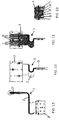
- Figure 1 shows a high conductance thermal link 1 that comprises two end fittings 3, 3' and a thermal conductive strap 2.
- the thermal conductive strap 2 comprises pyrolytic graphite layers arranged in stacks 5, and polyimide film 6 at least partially covering each stack 5 of pyrolytic graphite layers, with adhesive material between the pyrolytic graphite layers.
- the thermal conductive strap 2 has two opposite ends 4, each one of them arranged inside the corresponding end fitting 3, 3' (see figures 5-9 ), that houses the corresponding end 4 of the thermal conductive strap 2.
- This configuration of the high conductance thermal link 1 allows a better heat transfer between the pyrolytic graphite layers and end fittings 3, 3'.
- the layers of pyrolytic graphite can be arranged as sheets (i.e., with planar or flat shape).
- the stacks 5 of pyrolytic graphite in the ends 4 of the thermal conductive strap 4 lodged inside the end fittings 3, 3' are not covered by polyimide film 6 (i.e., they are only covered by polyimide film 6 in the intermediate section of the thermal conductive strap 2 between both ends 4).
- the end fittings 3, 3' can be composed of two symmetrical halves 9, that can be attached by joining means 10 (see figures 5 and 6 ), housing the corresponding ends 4 of the thermal conductive strap 2.
- the end fittings 3, 3' can be made of metal (for example, aluminium) or organic materials.
- Figures 10 to 13 show another complex embodiment of a high conductance thermal link 1 of the invention.
- the thermal link 1 of the invention has enough flexibility to be able to adapt to different needs and geometries.
- Figures 11 and 12 show the configuration of the ends 4 of the thermal conductive strap 2. It can be seen that the ends 4 of the thermal conductive strap 2 have a geometry with several protrusions 7 (in this case, more than two ones) separated by intermediate gaps 8.
- the thermal link1 has an optimized design at its ends, where pyrolytic graphite layers are placed in high conductivity adhesive to assure a good thermal conductivity between the thermal conductive straps 2 and the corresponding end fittings 3, 3'.
- the internal design of the ends of the thermal link 1 is a key factor to generate the conductivity in the normal direction of the thermal conductive strap 2, as the pyrolytic graphite has good conductive properties only in plane.
- the stacks 5 of pyrolytic graphite in the ends 4 of the thermal conductive strap 2 lodged inside the end fittings 3, 3' are not covered by polyimide film 6.
- Figure 14 shows a cross-section of a stack 5 of pyrolytic graphite layers covered by polyimide film 6.
- the thermal strap 2 has no limits in length or width, so it can adopt different geometries according to different needs (i.e., it can be rectangular, square, or in any desired shape with the desired dimensions).
- thermal link 1 of the invention does not transmit mechanical loads between the end fittings 3, 3' because of its high flexibility which decouples mechanically one end of the thermal strap 2 from the other.
Landscapes
- Engineering & Computer Science (AREA)
- Chemical & Material Sciences (AREA)
- Materials Engineering (AREA)
- General Health & Medical Sciences (AREA)
- Chemical Kinetics & Catalysis (AREA)
- Health & Medical Sciences (AREA)
- Toxicology (AREA)
- Environmental & Geological Engineering (AREA)
- Remote Sensing (AREA)
- Aviation & Aerospace Engineering (AREA)
- Physics & Mathematics (AREA)
- Biodiversity & Conservation Biology (AREA)
- Environmental Sciences (AREA)
- Combustion & Propulsion (AREA)
- Thermal Sciences (AREA)
- Life Sciences & Earth Sciences (AREA)
- Organic Chemistry (AREA)
- Cooling Or The Like Of Semiconductors Or Solid State Devices (AREA)
- Ceramic Engineering (AREA)
- Connector Housings Or Holding Contact Members (AREA)
- Carbon And Carbon Compounds (AREA)
- Combinations Of Printed Boards (AREA)
Abstract
Description
- This invention refers to a high conductance thermal link, specially used to deal with the thermal management of equipment and avionics on a spacecraft in a space environment.
- The thermal control of the equipment used in space based research is the key to a perfect performance of these complex tools which have highly demanding requirements.
- The thermal control system is responsible of maintaining component temperature ranges during the whole mission of a spacecraft or satellite. Thermal straps are a thermal path for heat transfer that is used as a tool to control these temperatures inside the spacecraft structure. A thermal path is the tracing of heat flow from the point where it enters the system, to the surface or point where it leaves the system.
- A usual part of these thermal control parts is a flexible thermal strip that ties the cooling instrument or equipment to the heat sink. It has to transport heat (i.e., it must have high conductance properties) and also have a flexibility that allows it to be set up on any precise position of the spacecraft structure, without reducing its performance. The mechanical and/or geometrical constraints are very important when designing the thermal control system of a flight hardware.
- Thermal strips are used in various industries as a system to control temperature variation on electrical and optical equipment. They are usually commercialized as straps with connectors at the ends, and are usually made of copper, aluminium or organic materials.
- Thermal links are a passive system of thermal control on the spacecraft. They have no mechanical moving parts or moving fluids. They have no power consumption, a low mass and are highly reliable.
- Heat may be transferred on satellites by conduction or by radiation. Thermal straps conduct heat from the equipment to radiators through conductive processes.
- Thermal links can be classified according to the material used in metallic links and graphite links; inside those two types, that can be foil or sheet made, or threaded wires links. Metallic thermal straps are the most widely used. They are made of aluminium alloys or copper. The flexibility of the metallic straps depends on the single wire diameter. The high robustness and reliability of these metals has made it a useful tool in space applications. However, its mass can be a drawback, mainly in the case of copper.
- The development of graphite based thermal links has opened a wide opportunity for weight reduction. They can be made of pyrolytic graphite or high conductive carbon fibers, for instance.
- An example of a construction that uses pyrolytic graphite for thermal management can be found in
US 5296310 A (referred to k-Core® product, commercialized by Thermacore), entitled "High Conductivity Hybrid Material for Thermal Management". -
EP 1025586 B1 refers to a "Flexible Heat Transfer Device and Method". The heat transfer device for transferring heat from a heat source to a heat sink comprises a high thermal conductivity core material of pyrolytic graphite or highly ordered pyrolytic graphite. -
EP 2597041 B refers to a thermal strap formed by fibres or foils and comprising a flexible middle section and two rigid end parts. The fibres or foils are embedded in a rigid matrix material thus forming the rigid end parts. - The laminar graphite is a material with good thermal conductivity properties in its plane, but with bad conductivity in the normal direction.
- Accordingly, there is a need to obtain a graphite based thermal links with enhanced conductance also in the normal direction.
- The object of the invention is to provide a thermal link with enhanced conductance, also in the normal direction.
- The invention provides a high conductance thermal link, that comprises:
- a thermal conductive strap comprising pyrolytic graphite layers arranged in stacks and polyimide film at least partially covering each stack, with adhesive material between the pyrolytic graphite layers, the thermal conductive strap having two opposite ends, and
- two end fittings that house the corresponding ends of the thermal conductive strap,
- The invention allows a better conductivity with respect to the prior art thermal links, including the metallic ones. Accordingly, it can dissipate the heat generated in the electronic and optical equipment in a better way, avoiding the overheating of the spacecraft or satellite.
- Another advantage of the invention is that it reduces the necessary mass with respect to the prior art thermal links.
- Another advantage of the invention is that it has no limits in length or width, so it can adopt different geometries according to different needs.
- Other characteristics and advantages of the present invention will be clear from the following detailed description of several embodiments illustrative of its object in relation to the attached figures.
-
-
Figure 1 shows a perspective view of an embodiment of the high conductance thermal link of the invention. -
Figure 2 shows a side view of the high conductance thermal link ofFigure 1 . -
Figure 3 shows a front view of one of the end fittings of the high conductance thermal link ofFigure 1 . -
Figure 4 shows a front view of the other end fitting of the high conductance thermal link ofFigure 1 . -
Figure 5 shows the cross-section A-A ofFigure3 . -
Figure 6 shows cross-section C-C ofFigure 4 . -
Figure 7 shows the cross-section D-D ofFigure 4 . -
Figures 8 and 9 show the cross-section B-B ofFigure 2 , corresponding to the end fittings. -
Figure 10 shows a perspective view of another complex embodiment of the high conductance thermal link of the invention. -
Figure 11 is a view of the high conductance thermal link ofFigure 10 , showing the configuration of one of the ends of the thermal conductive strap. -
Figure 12 shows the configuration of the other end of the thermal conductive strap. -
Figure 13 is another view of the high conductance thermal link ofFigure 10 . -
Figure 14 shows a cross-section of a stack of pyrolytic graphite layers covered by polyimide film. -
Figure 1 shows a high conductancethermal link 1 that comprises twoend fittings 3, 3' and a thermalconductive strap 2. - The thermal
conductive strap 2 comprises pyrolytic graphite layers arranged instacks 5, andpolyimide film 6 at least partially covering eachstack 5 of pyrolytic graphite layers, with adhesive material between the pyrolytic graphite layers. The thermalconductive strap 2 has twoopposite ends 4, each one of them arranged inside thecorresponding end fitting 3, 3' (seefigures 5-9 ), that houses thecorresponding end 4 of the thermalconductive strap 2. - In
figures 8 and 9 it can be seen that theends 4 of the thermalconductive strap 2 have a geometry with twoprotrusions 7 separated by anintermediate gap 8. - In the
ends 4 of the thermalconductive strap 2 there is an adhesive material between the pyrolytic graphite layers and between thestacks 5 of pyrolytic graphite layers. - This configuration of the high conductance
thermal link 1 allows a better heat transfer between the pyrolytic graphite layers andend fittings 3, 3'. - The layers of pyrolytic graphite can be arranged as sheets (i.e., with planar or flat shape).
- In one embodiment the
stacks 5 of pyrolytic graphite in theends 4 of the thermalconductive strap 4 lodged inside theend fittings 3, 3' are not covered by polyimide film 6 (i.e., they are only covered bypolyimide film 6 in the intermediate section of the thermalconductive strap 2 between both ends 4). - The
end fittings 3, 3' can be composed of twosymmetrical halves 9, that can be attached by joining means 10 (seefigures 5 and 6 ), housing the corresponding ends 4 of the thermalconductive strap 2. - The
end fittings 3, 3' can be made of metal (for example, aluminium) or organic materials. -
Figures 10 to 13 show another complex embodiment of a high conductancethermal link 1 of the invention. As it can be seen, thethermal link 1 of the invention has enough flexibility to be able to adapt to different needs and geometries. -
Figures 11 and 12 show the configuration of theends 4 of the thermalconductive strap 2. It can be seen that theends 4 of the thermalconductive strap 2 have a geometry with several protrusions 7 (in this case, more than two ones) separated byintermediate gaps 8. - In order to be able to obtain the enhanced performance, the thermal link1 has an optimized design at its ends, where pyrolytic graphite layers are placed in high conductivity adhesive to assure a good thermal conductivity between the thermal
conductive straps 2 and thecorresponding end fittings 3, 3'. - The internal design of the ends of the
thermal link 1 is a key factor to generate the conductivity in the normal direction of the thermalconductive strap 2, as the pyrolytic graphite has good conductive properties only in plane. - According to one embodiment, the
stacks 5 of pyrolytic graphite in theends 4 of the thermalconductive strap 2 lodged inside theend fittings 3, 3' are not covered bypolyimide film 6. -
Figure 14 shows a cross-section of astack 5 of pyrolytic graphite layers covered bypolyimide film 6. - The symmetrical configuration of the
end fittings 3, 3', together with the arrangement of thestacks 5 of pyrolytic graphite in theends 4 of the thermalconductive strap 2 lodged inside theend fittings 3, 3', allow that the heat can flow through the faces of theend fittings 3, 3' (i.e., it allows several thermal paths). - The
thermal strap 2 has no limits in length or width, so it can adopt different geometries according to different needs (i.e., it can be rectangular, square, or in any desired shape with the desired dimensions). - Another advantage is that the
thermal link 1 of the invention does not transmit mechanical loads between theend fittings 3, 3' because of its high flexibility which decouples mechanically one end of thethermal strap 2 from the other. - Although the present invention has been fully described in connection with preferred embodiments, it is evident that modifications may be introduced within the scope thereof, not considering this as limited by these embodiments, but by the contents of the following claims.
Claims (6)
- High conductance thermal link (1), that comprises:- a thermal conductive strap (2) comprising pyrolytic graphite layers arranged in stacks (5) and polyimide film (6) at least partially covering each stack (5), with adhesive material between the pyrolytic graphite layers, the thermal conductive strap (2) having two opposite ends (4), and- two end fittings (3, 3') that house the corresponding ends (4) of the thermal conductive strap (2),characterized in that
in the ends (4) of the thermal conductive strap (2) there is an adhesive material between the pyrolytic graphite layers and between the stacks (5) of pyrolytic graphite layers, and at least one of the ends (4) of the thermal conductive strap (2) has a geometry comprising several protrusions (7) separated by intermediate gaps (8). - High conductance thermal link (1) according to claim 1, wherein the layers of pyrolytic graphite are arranged as sheets.
- High conductance thermal link (1) according to any of the previous claims, wherein the stacks (5) of pyrolytic graphite in the ends (4) of the thermal conductive strap (2) lodged inside the end fittings (3, 3') are not covered by polyimide film (6).
- High conductance thermal link (1) according to any of the previous claims, wherein the end fittings (3, 3') comprise two symmetrical halves (9).
- High conductance thermal link (1) according to claim 4, wherein the two symmetrical halves (9) of the end fittings (3, 3') are attached by joining means (10).
- High conductance thermal link (1) according to any of the previous claims, wherein the end fittings (3, 3') are made of metal or of organic material.
Applications Claiming Priority (1)
| Application Number | Priority Date | Filing Date | Title |
|---|---|---|---|
| PCT/ES2017/070866 WO2019129896A1 (en) | 2017-12-29 | 2017-12-29 | High-conductance thermal connector |
Publications (2)
| Publication Number | Publication Date |
|---|---|
| EP3733527A1 true EP3733527A1 (en) | 2020-11-04 |
| EP3733527B1 EP3733527B1 (en) | 2022-08-17 |
Family
ID=61581333
Family Applications (1)
| Application Number | Title | Priority Date | Filing Date |
|---|---|---|---|
| EP17849810.1A Active EP3733527B1 (en) | 2017-12-29 | 2017-12-29 | High-conductance thermal connector |
Country Status (7)
| Country | Link |
|---|---|
| US (1) | US11521910B2 (en) |
| EP (1) | EP3733527B1 (en) |
| JP (1) | JP7133020B2 (en) |
| CN (1) | CN111587210A (en) |
| CA (1) | CA3086811A1 (en) |
| ES (1) | ES2935382T3 (en) |
| WO (1) | WO2019129896A1 (en) |
Families Citing this family (4)
| Publication number | Priority date | Publication date | Assignee | Title |
|---|---|---|---|---|
| US12328845B2 (en) * | 2021-12-20 | 2025-06-10 | Meta Platforms Technologies, Llc | Thermal conduit for electronic device |
| CN115585685A (en) * | 2022-01-05 | 2023-01-10 | 中国科学院微小卫星创新研究院 | Satellite in-orbit heat transfer device and manufacturing method thereof |
| FR3143179B1 (en) * | 2022-12-13 | 2025-11-21 | Airbus Defence & Space Sas | Electrical cable arrangement comprising at least one cable clamping device |
| FI20235273A1 (en) * | 2023-03-09 | 2024-09-10 | Teknologian Tutkimuskeskus Vtt Oy | Heating belt and method for producing a heating belt |
Family Cites Families (30)
| Publication number | Priority date | Publication date | Assignee | Title |
|---|---|---|---|---|
| US5296310A (en) | 1992-02-14 | 1994-03-22 | Materials Science Corporation | High conductivity hydrid material for thermal management |
| US5255738A (en) * | 1992-07-16 | 1993-10-26 | E-Systems, Inc. | Tapered thermal substrate for heat transfer applications and method for making same |
| JPH10126081A (en) * | 1996-10-17 | 1998-05-15 | Matsushita Electric Ind Co Ltd | Insulation device |
| EP1025586B1 (en) | 1997-09-19 | 2006-06-14 | The General Electric Company | Flexible heat transfer device and method |
| US6131651A (en) * | 1998-09-16 | 2000-10-17 | Advanced Ceramics Corporation | Flexible heat transfer device and method |
| US6286591B1 (en) * | 1999-11-08 | 2001-09-11 | Space Systems/Loral, Inc. | Thermal harness using thermal conductive fiber and polymer matrix material |
| US7166912B2 (en) * | 2001-04-05 | 2007-01-23 | Advanced Energy Technology Inc. | Isolated thermal interface |
| JP2002344095A (en) * | 2001-05-16 | 2002-11-29 | Matsushita Electric Ind Co Ltd | Composite circuit board |
| JP3480459B2 (en) * | 2001-09-19 | 2003-12-22 | 松下電器産業株式会社 | Graphite sheet |
| US6771502B2 (en) * | 2002-06-28 | 2004-08-03 | Advanced Energy Technology Inc. | Heat sink made from longer and shorter graphite sheets |
| AT412265B (en) * | 2002-11-12 | 2004-12-27 | Electrovac | HEAT EXTRACTION COMPONENT |
| US6919504B2 (en) * | 2002-12-19 | 2005-07-19 | 3M Innovative Properties Company | Flexible heat sink |
| CN100496186C (en) * | 2003-09-19 | 2009-06-03 | 通用电气公司 | Bulk high thermal conductivity material and method of making thereof |
| US7303820B2 (en) * | 2003-10-14 | 2007-12-04 | Graftech International Holdings Inc. | Heat spreader for display device |
| US20060068205A1 (en) * | 2004-09-24 | 2006-03-30 | Carbone Lorraine Composants | Composite material used for manufacturing heat exchanger fins with high thermal conductivity |
| CN201115224Y (en) * | 2007-05-23 | 2008-09-10 | 新高功能医用电子有限公司 | Heat dissipation connector module |
| US20090165302A1 (en) * | 2007-12-31 | 2009-07-02 | Slaton David S | Method of forming a heatsink |
| JP2010003981A (en) * | 2008-06-23 | 2010-01-07 | Kaneka Corp | Heat-conducting sheet with graphite oriented in thickness direction |
| FR2977121B1 (en) | 2011-06-22 | 2014-04-25 | Commissariat Energie Atomique | THERMAL MANAGEMENT SYSTEM WITH VARIABLE VOLUME MATERIAL |
| EP2597041A1 (en) | 2011-11-22 | 2013-05-29 | Active Space Technologies GmbH | Thermal strap |
| KR20130117909A (en) * | 2012-04-16 | 2013-10-29 | 박진섭 | Heat conduction tape having electric conductivity and fabricating method thereof |
| TW201410601A (en) * | 2012-09-06 | 2014-03-16 | 綠晶能源股份有限公司 | Flexible graphite paper and method for fabricating the same and augmented structure |
| US9271427B2 (en) * | 2012-11-28 | 2016-02-23 | Hamilton Sundstrand Corporation | Flexible thermal transfer strips |
| US20150075762A1 (en) * | 2013-09-18 | 2015-03-19 | Jeffri J. Narendra | Flexible composites containing graphite and fillers |
| US20150096731A1 (en) * | 2013-10-04 | 2015-04-09 | Specialty Minerals (Michigan) Inc. | Device and System for Dissipating Heat, and Method of Making Same |
| CN105765713A (en) * | 2013-11-12 | 2016-07-13 | 捷恩智株式会社 | Heat sink |
| DE102014000908A1 (en) * | 2014-01-28 | 2015-07-30 | Airbus Ds Gmbh | Thermal connection element and method for its production |
| CN204634261U (en) * | 2015-06-12 | 2015-09-09 | 东莞市思泉实业有限公司 | Multi-layer composite graphite heat sink |
| GB2551997B (en) * | 2016-07-05 | 2019-01-23 | Jaguar Land Rover Ltd | Battery cell arrangement |
| US20200307158A1 (en) * | 2019-03-27 | 2020-10-01 | Utah State University Space Dynamics Laboratory | Composite Thermal Strap |
-
2017
- 2017-12-29 EP EP17849810.1A patent/EP3733527B1/en active Active
- 2017-12-29 ES ES17849810T patent/ES2935382T3/en active Active
- 2017-12-29 US US16/957,671 patent/US11521910B2/en active Active
- 2017-12-29 CA CA3086811A patent/CA3086811A1/en active Pending
- 2017-12-29 WO PCT/ES2017/070866 patent/WO2019129896A1/en not_active Ceased
- 2017-12-29 JP JP2020535115A patent/JP7133020B2/en active Active
- 2017-12-29 CN CN201780098082.XA patent/CN111587210A/en active Pending
Also Published As
| Publication number | Publication date |
|---|---|
| JP7133020B2 (en) | 2022-09-07 |
| EP3733527B1 (en) | 2022-08-17 |
| CN111587210A (en) | 2020-08-25 |
| WO2019129896A1 (en) | 2019-07-04 |
| JP2021515978A (en) | 2021-06-24 |
| US20200328134A1 (en) | 2020-10-15 |
| US11521910B2 (en) | 2022-12-06 |
| CA3086811A1 (en) | 2019-07-04 |
| ES2935382T3 (en) | 2023-03-06 |
Similar Documents
| Publication | Publication Date | Title |
|---|---|---|
| EP3733527B1 (en) | High-conductance thermal connector | |
| US6257328B1 (en) | Thermal conductive unit and thermal connection structure using the same | |
| JP6117288B2 (en) | Cooling system | |
| US8004846B2 (en) | Heat radiator | |
| US8650886B2 (en) | Thermal spreader assembly with flexible liquid cooling loop having rigid tubing sections and flexible tubing sections | |
| US9222735B2 (en) | Compliant multilayered thermally-conductive interface assemblies | |
| US10991869B2 (en) | Thermoelectric device having a plurality of sealing materials | |
| CN208016185U (en) | heat sink | |
| CN101930952B (en) | Compliant multilayered thermally-conductive interface assemblies and memory modules including the same | |
| US10750639B2 (en) | Cooling memory modules | |
| US20190311970A1 (en) | Heat sink and cooling device | |
| EP2124009B1 (en) | Mixed carbon foam/metal foam heat exchanger | |
| US10034412B2 (en) | Device with heat transfer portion | |
| US20100321891A1 (en) | Avionics Chassis | |
| US20100321897A1 (en) | Compliant multilayered thermally-conductive interface assemblies | |
| US20180248238A1 (en) | Graphene enhanced cooling fin | |
| CN105794329B (en) | Electronic equipment | |
| CN104202947A (en) | A kind of flexible, lightweight and high-efficiency heat conduction cable | |
| JP2021077568A (en) | Laminated bus bar, method for designing laminated bus bar, and battery module | |
| US20110303403A1 (en) | Flexible Heat Exchanger | |
| CN113954448A (en) | Carbon-series flexible heat conduction belt with high heat conduction in plane and vertical direction and manufacturing method thereof | |
| US6885564B2 (en) | Electronics box having internal circuit cards interconnected to external connectors sans motherboard | |
| US10480833B2 (en) | Heat-transferring and electrically connecting device and electronic device | |
| US20180287232A1 (en) | Battery system | |
| CN111010852B (en) | Electronic device |
Legal Events
| Date | Code | Title | Description |
|---|---|---|---|
| STAA | Information on the status of an ep patent application or granted ep patent |
Free format text: STATUS: UNKNOWN |
|
| STAA | Information on the status of an ep patent application or granted ep patent |
Free format text: STATUS: THE INTERNATIONAL PUBLICATION HAS BEEN MADE |
|
| PUAI | Public reference made under article 153(3) epc to a published international application that has entered the european phase |
Free format text: ORIGINAL CODE: 0009012 |
|
| STAA | Information on the status of an ep patent application or granted ep patent |
Free format text: STATUS: REQUEST FOR EXAMINATION WAS MADE |
|
| 17P | Request for examination filed |
Effective date: 20200708 |
|
| AK | Designated contracting states |
Kind code of ref document: A1 Designated state(s): AL AT BE BG CH CY CZ DE DK EE ES FI FR GB GR HR HU IE IS IT LI LT LU LV MC MK MT NL NO PL PT RO RS SE SI SK SM TR |
|
| AX | Request for extension of the european patent |
Extension state: BA ME |
|
| DAV | Request for validation of the european patent (deleted) | ||
| DAX | Request for extension of the european patent (deleted) | ||
| GRAP | Despatch of communication of intention to grant a patent |
Free format text: ORIGINAL CODE: EPIDOSNIGR1 |
|
| STAA | Information on the status of an ep patent application or granted ep patent |
Free format text: STATUS: GRANT OF PATENT IS INTENDED |
|
| RIC1 | Information provided on ipc code assigned before grant |
Ipc: C09K 5/14 20060101ALI20220217BHEP Ipc: H01L 23/373 20060101ALI20220217BHEP Ipc: H01L 23/367 20060101ALI20220217BHEP Ipc: F28F 21/02 20060101ALI20220217BHEP Ipc: B64G 1/50 20060101AFI20220217BHEP |
|
| INTG | Intention to grant announced |
Effective date: 20220323 |
|
| GRAS | Grant fee paid |
Free format text: ORIGINAL CODE: EPIDOSNIGR3 |
|
| GRAA | (expected) grant |
Free format text: ORIGINAL CODE: 0009210 |
|
| STAA | Information on the status of an ep patent application or granted ep patent |
Free format text: STATUS: THE PATENT HAS BEEN GRANTED |
|
| AK | Designated contracting states |
Kind code of ref document: B1 Designated state(s): AL AT BE BG CH CY CZ DE DK EE ES FI FR GB GR HR HU IE IS IT LI LT LU LV MC MK MT NL NO PL PT RO RS SE SI SK SM TR |
|
| REG | Reference to a national code |
Ref country code: CH Ref legal event code: EP |
|
| REG | Reference to a national code |
Ref country code: DE Ref legal event code: R096 Ref document number: 602017060830 Country of ref document: DE |
|
| REG | Reference to a national code |
Ref country code: IE Ref legal event code: FG4D |
|
| REG | Reference to a national code |
Ref country code: AT Ref legal event code: REF Ref document number: 1512030 Country of ref document: AT Kind code of ref document: T Effective date: 20220915 |
|
| REG | Reference to a national code |
Ref country code: NL Ref legal event code: FP |
|
| REG | Reference to a national code |
Ref country code: LT Ref legal event code: MG9D |
|
| PG25 | Lapsed in a contracting state [announced via postgrant information from national office to epo] |
Ref country code: SE Free format text: LAPSE BECAUSE OF FAILURE TO SUBMIT A TRANSLATION OF THE DESCRIPTION OR TO PAY THE FEE WITHIN THE PRESCRIBED TIME-LIMIT Effective date: 20220817 Ref country code: RS Free format text: LAPSE BECAUSE OF FAILURE TO SUBMIT A TRANSLATION OF THE DESCRIPTION OR TO PAY THE FEE WITHIN THE PRESCRIBED TIME-LIMIT Effective date: 20220817 Ref country code: PT Free format text: LAPSE BECAUSE OF FAILURE TO SUBMIT A TRANSLATION OF THE DESCRIPTION OR TO PAY THE FEE WITHIN THE PRESCRIBED TIME-LIMIT Effective date: 20221219 Ref country code: NO Free format text: LAPSE BECAUSE OF FAILURE TO SUBMIT A TRANSLATION OF THE DESCRIPTION OR TO PAY THE FEE WITHIN THE PRESCRIBED TIME-LIMIT Effective date: 20221117 Ref country code: LV Free format text: LAPSE BECAUSE OF FAILURE TO SUBMIT A TRANSLATION OF THE DESCRIPTION OR TO PAY THE FEE WITHIN THE PRESCRIBED TIME-LIMIT Effective date: 20220817 Ref country code: LT Free format text: LAPSE BECAUSE OF FAILURE TO SUBMIT A TRANSLATION OF THE DESCRIPTION OR TO PAY THE FEE WITHIN THE PRESCRIBED TIME-LIMIT Effective date: 20220817 Ref country code: FI Free format text: LAPSE BECAUSE OF FAILURE TO SUBMIT A TRANSLATION OF THE DESCRIPTION OR TO PAY THE FEE WITHIN THE PRESCRIBED TIME-LIMIT Effective date: 20220817 |
|
| PG25 | Lapsed in a contracting state [announced via postgrant information from national office to epo] |
Ref country code: PL Free format text: LAPSE BECAUSE OF FAILURE TO SUBMIT A TRANSLATION OF THE DESCRIPTION OR TO PAY THE FEE WITHIN THE PRESCRIBED TIME-LIMIT Effective date: 20220817 Ref country code: IS Free format text: LAPSE BECAUSE OF FAILURE TO SUBMIT A TRANSLATION OF THE DESCRIPTION OR TO PAY THE FEE WITHIN THE PRESCRIBED TIME-LIMIT Effective date: 20221217 Ref country code: HR Free format text: LAPSE BECAUSE OF FAILURE TO SUBMIT A TRANSLATION OF THE DESCRIPTION OR TO PAY THE FEE WITHIN THE PRESCRIBED TIME-LIMIT Effective date: 20220817 Ref country code: GR Free format text: LAPSE BECAUSE OF FAILURE TO SUBMIT A TRANSLATION OF THE DESCRIPTION OR TO PAY THE FEE WITHIN THE PRESCRIBED TIME-LIMIT Effective date: 20221118 |
|
| REG | Reference to a national code |
Ref country code: ES Ref legal event code: FG2A Ref document number: 2935382 Country of ref document: ES Kind code of ref document: T3 Effective date: 20230306 |
|
| PG25 | Lapsed in a contracting state [announced via postgrant information from national office to epo] |
Ref country code: SM Free format text: LAPSE BECAUSE OF FAILURE TO SUBMIT A TRANSLATION OF THE DESCRIPTION OR TO PAY THE FEE WITHIN THE PRESCRIBED TIME-LIMIT Effective date: 20220817 Ref country code: RO Free format text: LAPSE BECAUSE OF FAILURE TO SUBMIT A TRANSLATION OF THE DESCRIPTION OR TO PAY THE FEE WITHIN THE PRESCRIBED TIME-LIMIT Effective date: 20220817 Ref country code: DK Free format text: LAPSE BECAUSE OF FAILURE TO SUBMIT A TRANSLATION OF THE DESCRIPTION OR TO PAY THE FEE WITHIN THE PRESCRIBED TIME-LIMIT Effective date: 20220817 Ref country code: CZ Free format text: LAPSE BECAUSE OF FAILURE TO SUBMIT A TRANSLATION OF THE DESCRIPTION OR TO PAY THE FEE WITHIN THE PRESCRIBED TIME-LIMIT Effective date: 20220817 |
|
| REG | Reference to a national code |
Ref country code: DE Ref legal event code: R097 Ref document number: 602017060830 Country of ref document: DE |
|
| PG25 | Lapsed in a contracting state [announced via postgrant information from national office to epo] |
Ref country code: SK Free format text: LAPSE BECAUSE OF FAILURE TO SUBMIT A TRANSLATION OF THE DESCRIPTION OR TO PAY THE FEE WITHIN THE PRESCRIBED TIME-LIMIT Effective date: 20220817 Ref country code: EE Free format text: LAPSE BECAUSE OF FAILURE TO SUBMIT A TRANSLATION OF THE DESCRIPTION OR TO PAY THE FEE WITHIN THE PRESCRIBED TIME-LIMIT Effective date: 20220817 |
|
| PLBE | No opposition filed within time limit |
Free format text: ORIGINAL CODE: 0009261 |
|
| STAA | Information on the status of an ep patent application or granted ep patent |
Free format text: STATUS: NO OPPOSITION FILED WITHIN TIME LIMIT |
|
| PG25 | Lapsed in a contracting state [announced via postgrant information from national office to epo] |
Ref country code: AL Free format text: LAPSE BECAUSE OF FAILURE TO SUBMIT A TRANSLATION OF THE DESCRIPTION OR TO PAY THE FEE WITHIN THE PRESCRIBED TIME-LIMIT Effective date: 20220817 |
|
| 26N | No opposition filed |
Effective date: 20230519 |
|
| PG25 | Lapsed in a contracting state [announced via postgrant information from national office to epo] |
Ref country code: SI Free format text: LAPSE BECAUSE OF FAILURE TO SUBMIT A TRANSLATION OF THE DESCRIPTION OR TO PAY THE FEE WITHIN THE PRESCRIBED TIME-LIMIT Effective date: 20220817 |
|
| PG25 | Lapsed in a contracting state [announced via postgrant information from national office to epo] |
Ref country code: IE Free format text: LAPSE BECAUSE OF NON-PAYMENT OF DUE FEES Effective date: 20221229 |
|
| PG25 | Lapsed in a contracting state [announced via postgrant information from national office to epo] |
Ref country code: CY Free format text: LAPSE BECAUSE OF FAILURE TO SUBMIT A TRANSLATION OF THE DESCRIPTION OR TO PAY THE FEE WITHIN THE PRESCRIBED TIME-LIMIT Effective date: 20220817 |
|
| PG25 | Lapsed in a contracting state [announced via postgrant information from national office to epo] |
Ref country code: MK Free format text: LAPSE BECAUSE OF FAILURE TO SUBMIT A TRANSLATION OF THE DESCRIPTION OR TO PAY THE FEE WITHIN THE PRESCRIBED TIME-LIMIT Effective date: 20220817 Ref country code: IT Free format text: LAPSE BECAUSE OF FAILURE TO SUBMIT A TRANSLATION OF THE DESCRIPTION OR TO PAY THE FEE WITHIN THE PRESCRIBED TIME-LIMIT Effective date: 20220817 Ref country code: HU Free format text: LAPSE BECAUSE OF FAILURE TO SUBMIT A TRANSLATION OF THE DESCRIPTION OR TO PAY THE FEE WITHIN THE PRESCRIBED TIME-LIMIT; INVALID AB INITIO Effective date: 20171229 |
|
| PG25 | Lapsed in a contracting state [announced via postgrant information from national office to epo] |
Ref country code: MC Free format text: LAPSE BECAUSE OF FAILURE TO SUBMIT A TRANSLATION OF THE DESCRIPTION OR TO PAY THE FEE WITHIN THE PRESCRIBED TIME-LIMIT Effective date: 20220817 |
|
| PG25 | Lapsed in a contracting state [announced via postgrant information from national office to epo] |
Ref country code: TR Free format text: LAPSE BECAUSE OF FAILURE TO SUBMIT A TRANSLATION OF THE DESCRIPTION OR TO PAY THE FEE WITHIN THE PRESCRIBED TIME-LIMIT Effective date: 20220817 Ref country code: MC Free format text: LAPSE BECAUSE OF FAILURE TO SUBMIT A TRANSLATION OF THE DESCRIPTION OR TO PAY THE FEE WITHIN THE PRESCRIBED TIME-LIMIT Effective date: 20220817 |
|
| PG25 | Lapsed in a contracting state [announced via postgrant information from national office to epo] |
Ref country code: BG Free format text: LAPSE BECAUSE OF FAILURE TO SUBMIT A TRANSLATION OF THE DESCRIPTION OR TO PAY THE FEE WITHIN THE PRESCRIBED TIME-LIMIT Effective date: 20220817 |
|
| REG | Reference to a national code |
Ref country code: AT Ref legal event code: UEP Ref document number: 1512030 Country of ref document: AT Kind code of ref document: T Effective date: 20220817 |
|
| PG25 | Lapsed in a contracting state [announced via postgrant information from national office to epo] |
Ref country code: MT Free format text: LAPSE BECAUSE OF FAILURE TO SUBMIT A TRANSLATION OF THE DESCRIPTION OR TO PAY THE FEE WITHIN THE PRESCRIBED TIME-LIMIT Effective date: 20220817 |
|
| REG | Reference to a national code |
Ref country code: CH Ref legal event code: U11 Free format text: ST27 STATUS EVENT CODE: U-0-0-U10-U11 (AS PROVIDED BY THE NATIONAL OFFICE) Effective date: 20260101 |
|
| PGFP | Annual fee paid to national office [announced via postgrant information from national office to epo] |
Ref country code: DE Payment date: 20251211 Year of fee payment: 9 |
|
| PGFP | Annual fee paid to national office [announced via postgrant information from national office to epo] |
Ref country code: GB Payment date: 20251219 Year of fee payment: 9 |
|
| PGFP | Annual fee paid to national office [announced via postgrant information from national office to epo] |
Ref country code: AT Payment date: 20251222 Year of fee payment: 9 |
|
| PGFP | Annual fee paid to national office [announced via postgrant information from national office to epo] |
Ref country code: LU Payment date: 20251219 Year of fee payment: 9 Ref country code: FR Payment date: 20251229 Year of fee payment: 9 Ref country code: NL Payment date: 20251219 Year of fee payment: 9 |
|
| PGFP | Annual fee paid to national office [announced via postgrant information from national office to epo] |
Ref country code: BE Payment date: 20251219 Year of fee payment: 9 |
|
| PGFP | Annual fee paid to national office [announced via postgrant information from national office to epo] |
Ref country code: ES Payment date: 20260130 Year of fee payment: 9 |
|
| PGFP | Annual fee paid to national office [announced via postgrant information from national office to epo] |
Ref country code: CH Payment date: 20260101 Year of fee payment: 9 |