EP3733502B1 - Power generation system for ships - Google Patents
Power generation system for ships Download PDFInfo
- Publication number
- EP3733502B1 EP3733502B1 EP18906952.9A EP18906952A EP3733502B1 EP 3733502 B1 EP3733502 B1 EP 3733502B1 EP 18906952 A EP18906952 A EP 18906952A EP 3733502 B1 EP3733502 B1 EP 3733502B1
- Authority
- EP
- European Patent Office
- Prior art keywords
- generator
- power
- ship
- secondary battery
- control device
- Prior art date
- Legal status (The legal status is an assumption and is not a legal conclusion. Google has not performed a legal analysis and makes no representation as to the accuracy of the status listed.)
- Active
Links
Images






Classifications
-
- B—PERFORMING OPERATIONS; TRANSPORTING
- B63—SHIPS OR OTHER WATERBORNE VESSELS; RELATED EQUIPMENT
- B63J—AUXILIARIES ON VESSELS
- B63J3/00—Driving of auxiliaries
- B63J3/04—Driving of auxiliaries from power plant other than propulsion power plant
-
- H—ELECTRICITY
- H02—GENERATION; CONVERSION OR DISTRIBUTION OF ELECTRIC POWER
- H02J—ELECTRIC POWER NETWORKS; CIRCUIT ARRANGEMENTS OR SYSTEMS FOR SUPPLYING OR DISTRIBUTING ELECTRIC POWER; SYSTEMS FOR STORING ELECTRIC ENERGY
- H02J3/00—Circuit arrangements for AC mains or AC distribution networks
- H02J3/28—Arrangements for balancing of the load in networks by storage of energy
- H02J3/32—Arrangements for balancing of the load in networks by storage of energy using batteries or super capacitors with converting means
- H02J3/322—Arrangements for balancing of the load in networks by storage of energy using batteries or super capacitors with converting means the battery being on-board an electric or hybrid vehicle, e.g. vehicle to grid arrangements [V2G], power aggregation, use of the battery for network load balancing, coordinated or cooperative battery charging
-
- B—PERFORMING OPERATIONS; TRANSPORTING
- B63—SHIPS OR OTHER WATERBORNE VESSELS; RELATED EQUIPMENT
- B63J—AUXILIARIES ON VESSELS
- B63J3/00—Driving of auxiliaries
- B63J3/02—Driving of auxiliaries from propulsion power plant
-
- H—ELECTRICITY
- H02—GENERATION; CONVERSION OR DISTRIBUTION OF ELECTRIC POWER
- H02J—ELECTRIC POWER NETWORKS; CIRCUIT ARRANGEMENTS OR SYSTEMS FOR SUPPLYING OR DISTRIBUTING ELECTRIC POWER; SYSTEMS FOR STORING ELECTRIC ENERGY
- H02J7/00—Circuit arrangements for charging or discharging batteries or for supplying loads from batteries
- H02J7/34—Parallel operation in networks using both storage and other DC sources, e.g. providing buffering
-
- B—PERFORMING OPERATIONS; TRANSPORTING
- B63—SHIPS OR OTHER WATERBORNE VESSELS; RELATED EQUIPMENT
- B63H—MARINE PROPULSION OR STEERING
- B63H21/00—Use of propulsion power plant or units on vessels
- B63H21/20—Use of propulsion power plant or units on vessels the vessels being powered by combinations of different types of propulsion units
- B63H2021/202—Use of propulsion power plant or units on vessels the vessels being powered by combinations of different types of propulsion units of hybrid electric type
-
- B—PERFORMING OPERATIONS; TRANSPORTING
- B63—SHIPS OR OTHER WATERBORNE VESSELS; RELATED EQUIPMENT
- B63J—AUXILIARIES ON VESSELS
- B63J3/00—Driving of auxiliaries
- B63J2003/001—Driving of auxiliaries characterised by type of power supply, or power transmission, e.g. by using electric power or steam
- B63J2003/002—Driving of auxiliaries characterised by type of power supply, or power transmission, e.g. by using electric power or steam by using electric power
-
- H—ELECTRICITY
- H02—GENERATION; CONVERSION OR DISTRIBUTION OF ELECTRIC POWER
- H02J—ELECTRIC POWER NETWORKS; CIRCUIT ARRANGEMENTS OR SYSTEMS FOR SUPPLYING OR DISTRIBUTING ELECTRIC POWER; SYSTEMS FOR STORING ELECTRIC ENERGY
- H02J2105/00—Networks for supplying or distributing electric power characterised by their spatial reach or by the load
- H02J2105/30—Networks for supplying or distributing electric power characterised by their spatial reach or by the load the load networks being external to vehicles, i.e. exchanging power with vehicles
- H02J2105/31—Networks for supplying or distributing electric power characterised by their spatial reach or by the load the load networks being external to vehicles, i.e. exchanging power with vehicles for ships or vessels
-
- H—ELECTRICITY
- H02—GENERATION; CONVERSION OR DISTRIBUTION OF ELECTRIC POWER
- H02P—CONTROL OR REGULATION OF ELECTRIC MOTORS, ELECTRIC GENERATORS OR DYNAMO-ELECTRIC CONVERTERS; CONTROLLING TRANSFORMERS, REACTORS OR CHOKE COILS
- H02P9/00—Arrangements for controlling electric generators for the purpose of obtaining a desired output
- H02P9/04—Control effected upon non-electric prime mover and dependent upon electric output value of the generator
Definitions
- the present invention relates to a power generation system for ships.
- a plurality (for example, three) of generators are mounted in view of redundancy or needed maximum power, and each generator is operated such that an operation time becomes uniform.
- the maximum power is needed, for example, in a case where equipment, such as a bow thruster, is used during entry and departure.
- the three generators are operated under a high load.
- power is supplied to the interior of the ship using two generators, and a remaining one generator is made on standby.
- PTL 1 discloses an electric motor system that includes a generator and a secondary battery, and can be operated with high efficiency even though requested torque and a requested rotation speed to a rotation output are changed.
- PTL 2 discloses a double-diesel generating set and lithium battery hybrid power ship structure which comprises an electric propulsion system.
- the electric propulsion system comprises two diesel generating sets, a lithium battery pack and an electric motor, wherein the two diesel generating sets, the lithium battery pack and the electric motor are connected with a direct-current bus, the electric motor is also connected with a propeller, the direct-current bus is also connected with shore power, and a power controller receives power signals of the electric motor and electrical charge status signals of the lithium battery pack and sends power control signals to the two diesel generating sets and a DC/DC convertor.
- PTL 3 discloses a ship and a power management method of the ship.
- the ship comprises: a power grid; at least one generator that is connected to the power grid and supplies electricity to the power grid; a high-capacity battery connected to the power grid, and charged by receiving the electricity from the power grid or discharged to supply power to the power grid; a plurality of load components connected to the power grid; and a controller for receiving generator load information from the at least one generator, sensing a voltage of the power grid to calculate a current load and an average load, and controlling the generator to bear the average load and the high-capacity battery to bear a difference load between the current load and the average load.
- PTL 4 discloses a power system for dynamic positioning of a vessel.
- the power system reduces fuel consumption, carbon buildup deposits and the risk of cylinder bore glazing while in combustion engine driven generators and provides an adequate protection against blackouts.
- the power system includes first and second combustion engine driven generators, a battery unit, and a converter unit arranged to provide power to the vessel from the battery unit.
- a first operational state of the power system in which the first combustion engine driven generator is arranged to deliver power to the vessel, and a second operational state, in which the first generator is subject to a fault, the second combustion engine driven generator arranged to deliver power to the vessel, and the converter unit is arranged to deliver power to the vessel during transition between the states.
- an object of the invention is to suppress deterioration of fuel efficiency of generators during normal sailing using a secondary battery in a ship.
- a power generation system for ships of the invention includes a plurality of generators that supply power to the interior of a ship, a secondary battery that stores power output from the plurality of generators and supplies the stored power to the interior of the ship, and a control device that supplies power to the ship using a first generator among the plurality of generators and the secondary battery during normal sailing of the ship.
- the control device charges the secondary battery so as to enable output of power equivalent to that of the first generator during entry and departure of the ship.
- the secondary battery has capacity equal to or greater than 90% and equal to or less than 120% of a rated power of the first generator.
- the secondary battery can be used in the same manner as the generators. Accordingly, it is possible to improve the fuel efficiency of the generators.
- control device supplies power to the interior of the ship using the first generator and a second generator among the plurality of generators, and charges the secondary battery using a third generator among the plurality of generators.
- control device supplies power to the interior of the ship using the first generator and a second generator among the plurality of generators, and charges the secondary battery using surplus power out of power supplied to the interior of the ship.
- the power generation system further includes a shaft generator provided in a rotary shaft of propulsion equipment.
- control device supplies power to the interior of the ship using the first generator and a second generator among the plurality of generators and charges the secondary battery using a third generator among the plurality of generators and the shaft generator.
- control device supplies power to the interior of the ship using the first generator and the shaft generator, and charges the secondary battery using a second generator among the plurality of generators.
- control device supplies power to the interior of the ship using the first generator and a second generator among the plurality of generators, charges the secondary battery using a third generator among the plurality of generators, and supplies power to the shaft generator using the secondary battery.
- control device supplies power to the interior of the ship using the first generator and a second generator among the plurality of generators, and charges the secondary battery using surplus power out of power supplied to the interior of the ship and the shaft generator.
- control device supplies power to the interior of the ship using the first generator and a second generator among the plurality of generators, charges the secondary battery using surplus power out of power supplied to the interior of the ship, and supplies power to the shaft generator using the secondary battery.
- Fig. 1 is a block diagram showing the configuration of the power generation system according to the first embodiment of the invention.
- a power generation system 1 includes a main generator 10 and a control device 20.
- the main generator 10 has a first generator 11, a second generator 12, a third generator 13, and a secondary battery 14.
- the power generation system 1 has three generators, this is for illustration, and is not intended to limit the invention.
- the power generation system 1 may have more generators.
- the first generator 11, the second generator 12, and the third generator 13 are generators that are provided in the interior of a ship.
- the first generator 11, the second generator 12, and the third generator 13 supply power to respective facilities that are provided in the interior of the ship. It is preferable that the first generator 11, the second generator 12, and the third generator 13 have the same rated power.
- the rated output of each of the first generator 11, the second generator 12, and the third generator 13 is, for example, 1000 kW.
- the rated output of each of the first generator 11, the second generator 12, and the third generator 13 may be set according to power needed during entry and departure of the ship.
- the secondary battery 14 is provided in the interior of the ship and supplies power to respective facilities that are provided in the interior of the ship.
- the secondary battery 14 supplies, for example, power, which is insufficient for power supplied to the interior or the ship using one generator operated under a high load (for example, 90%) out of power needed in the interior of the ship, to the interior of the ship.
- the secondary battery 14 is charged using the first generator 11, the second generator 12, and the third generator 13.
- the rated power of the secondary battery 14 is, for example, 1500 kW in a case where the rated power of each of the first generator 11, the second generator 12, and the third generator 13 is 1000 kW.
- the secondary battery 14 is a comparatively large-capacity secondary battery, and can output power as much as each of the first generator 11, the second generator 12, and third generator 13. Specifically, it is preferable that the secondary battery 14 can output power equal to or greater than 90% and equal to or less than 120% of the rated output of each of the generators.
- An upper limit of the capacity of the secondary battery 14 is decided in view of the cycle characteristic of the secondary battery 14. For example, the upper limit of the capacity of the secondary battery 14 is decided such that power equal to or greater than 90% of the rated power of the third generator 13 can be output from the first generator 11 even though the capacity of the secondary battery 14 is deteriorated to 80%. For this reason, the secondary battery 14 can be used instead of the first generator 11, the second generator 12, and the third generator 13.
- the control device 20 controls the first generator 11, the second generator 12, the third generator 13, and the secondary battery 14. Specifically, the control device 20 expands and executes a program stored in a storage device (not shown), thereby controlling the first generator 11, the second generator 12, the third generator 13, and the secondary battery 14.
- the control device 20 can be implemented by an electronic circuit including a central processing unit (CPU), or the like.
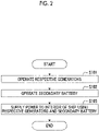
- Fig. 2 is a flowchart showing the operation of the power generation system 1 during entry and departure of the ship.
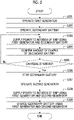
- Fig. 3 is a flowchart showing the operation of the power generation system 1 during normal sailing of the ship.
- power needed during entry and departure of the ship is 4500 kW
- power needed during normal sailing is 1800 kW
- the invention is not limited thereto.
- the control device 20 operates the first generator 11, the second generator 12, and the third generator 13 (Step S101).
- the control device 20 operates the first generator 11, the second generator 12, and the third generator 13 with the rated output. It is assumed that the rated power of each of the first generator 11, the second generator 12, and the third generator 13 is 1000 kW. That is, the control device 20 makes the first generator 11, the second generator 12, and the third generator 13 output power of 3000 kW. Then, the control device 20 progresses to Step S102.
- the control device 20 operates the secondary battery 14 (Step S102).
- the secondary battery 14 is charged so as to enable output of power as much as each of the first generator 11, the second generator 12, and the third generator 13 during normal sailing.
- the control device 20 makes the secondary battery 14 output power of 1500 kW. Then, the control device 20 progresses to Step S103.
- the control device 20 supplies power of 4500 kW to the interior of the ship using the first generator 11, the second generator 12, the third generator 13, and the secondary battery 14 (Step S103).
- the control device 20 operates the first generator 11 (Step S201).
- the control device 20 operates, for example, the first generator 11 under a high load (for example, 90% of the rated output), and makes the second generator 12 and the third generator 13 on standby. Specifically, in a case where the rated power of the first generator is 1000 kW, the control device 20 makes the first generator 11 output power of 900 kW. Then, the control device 20 progresses to Step S202.
- the control device 20 operates the secondary battery 14 (Step S202).
- the control device 20 makes power needed in the interior of the ship be output. For example, since power needed in the interior of the ship is 1800 kW, and the first generator 11 outputs power of 900 kW, the control device 20 makes the secondary battery 14 output insufficient power of 900 kW. Then, the control device 20 progresses to Step S203.
- the control device 20 supplies power of 1800 kW to the interior of the ship using the first generator 11 and the secondary battery 14 (Step S203). Then, the control device 20 progresses to Step S204.
- control device 20 confirms an amount of charge of the secondary battery 14 (Step S204). Then, the control device 20 progresses to Step S205.
- Step S205 In a case where the secondary battery 14 does not need charging (in Step S205, "No"), the control device 20 returns to Step S203. That is, in a case where the amount of charge of the secondary battery 14 is sufficient, power is continued to be supplied to the interior of the ship using the first generator 11 and the secondary battery 14. On the other hand, in a case where the secondary battery 14 needs charging (in Step S205, "Yes"), the control device 20 progresses to Step S206.
- a case where the secondary battery 14 needs charging means, for example, a case where power equivalent to that of each of the generators cannot be output during entry and departure.
- the control device 20 stops the secondary battery (Step S206). Then, the control device 20 progresses to Step S207.
- the control device 20 operates the second generator 12 and the third generator 13 (Step S207).
- the control device 20 operates the second generator 12 and the third generator 13 under a high load (for example, 90% of the rated power).
- a high load for example, 90% of the rated power.
- the control device 20 makes the second generator 12 and the third generator 13 output power of 900 kW. That is, the control device 20 operates the three generators of the first generator 11, the second generator 12, and the third generator 13 under a high load. Then, the control device 20 progresses to Step S208.
- the control device 20 supplies power of 1800 kW needed in the interior of the ship using the first generator 11 and the second generator 12 (Step S208). Then, the control device 20 progresses to Step S209.
- the control device 20 charges the secondary battery 14 using the third generator 13 (Step S209).
- the control device 20 charges the secondary battery 14 using the third generator 13 such that the ship can secure power needed during entry and departure.
- the secondary battery 14 is charged so as to enable output of power of 1500 kW. Since the first generator 11, the second generator 12, and the third generator 13 have the same rated output, the first generator 11, the second generator 12, and the third generator 13 are operated in a rotating manner such that an operation rate becomes the same.
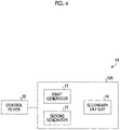
- FIG. 4 is a block diagram showing the configuration of a power generation system 1A according to a modification example of the first embodiment.
- the power generation system 1A includes a main generator 10A and a control device 20.
- the main generator 10A has a first generator 11, a second generator 12, and a secondary battery 14. That is, the power generation system 1A is different from the power generation system 1 in that power is supplied to a ship using the two generators and the secondary battery.
- the rated output of each of the first generator 11 and the second generator 12 is 1500 kW in a case where power needed during entry and departure of the ship is 4500 kW.
- Fig. 5 is a flowchart showing the operation of the power generation system 1A during normal sailing of the ship.
- the operation during entry and departure is the same as in the power generation system 1, and thus, description thereof will not be repeated.
- power needed during entry and departure of the ship is 4500 kW
- power needed during normal sailing is 1800 kW
- the control device 20 operates the first generator 11 (Step S301).
- the control device 20 operates, for example, the first generator 11 under a high load (for example, 90% of the rated power), and makes the second generator 12 on standby.
- the control device 20 makes the first generator 11 output power of 1350 kW. Then, the control device 20 progresses to Step S302.
- the control device 20 operates the secondary battery 14 (Step S302).
- the control device 20 makes power needed in the interior of the ship be output. For example, since power needed in the interior of the ship is 1800 kW, and the first generator 11 outputs power of 1350 kW, the control device 20 makes the secondary battery 14 output insufficient power of 450 kW. Then, the control device 20 progresses to Step S303.
- the control device 20 supplies power of 1800 kW to the interior of the ship using the first generator 11 and the secondary battery 14 (Step S303). Then, the control device 20 progresses to Step S304.
- control device 20 confirms an amount of charge of the secondary battery 14(Step S304). Then, the control device 20 progresses to Step S305.
- Step S305 In a case where the secondary battery 14 does not need charging (in Step S305, "No"), the control device 20 returns to Step S303. On the other hand, in a case where the secondary battery 14 needs charging (in Step S305, "Yes"), the control device 20 progresses to Step S306.
- the control device 20 stops the secondary battery 14 (Step S306). Then, the control device 20 progresses to Step S307.
- the control device 20 operates the second generator 12 (Step S307).
- the control device 20 operates, for example, the second generator 12 under a high load (for example, 90% of the rated power).
- the control device 20 makes the second generator 12 output power of 1350 kW. That is, the control device 20 operates the first generator 11 and the second generator 12 under a high load. Then, the control device 20 progresses to Step S308.
- the control device 20 supplies power of 1800 kW needed in the interior of the ship using the first generator 11 and the second generator 12 (Step S308). Then, the control device 20 progresses to Step S309.
- the control device 20 charges the secondary battery 14 using the first generator 11 and the second generator 12 (Step S309).
- the secondary battery 14 is charged using surplus power out of power supplied from the first generator 11 and the second generator 12 to the interior of the ship such that the ship can secure power needed during entry and departure.
- the control device 20 charges the secondary battery 14 using surplus power of 900 kW.
- the use of the secondary battery enables reduction in the rated output of each of the generators compared to the related art, during normal sailing, it is possible to constantly operate the respective generators under a high load. Accordingly, in the embodiment, it is possible to suppress deterioration of the fuel efficiency of the power generation system during normal sailing of the ship.
- the main engine is powered by a diesel engine
- the main engine may be powered electrically.
- a plurality of generators are further mounted, whereby the embodiment can be applied. With this, even though the main engine is electrically driven, it is possible to operate the respective generators under a high load while providing power using the secondary battery. Accordingly, even though the main engine is electrically driven, it is possible to suppress deterioration of fuel efficiency.
- FIG. 6 is a block diagram showing the configuration of the power generation system 1B according to the second embodiment of the invention.
- the power generation system 1B includes a main generator 10, a control device 20, a shaft generator 30, and a propeller 40.
- the shaft generator 30 is a rotary generator provided in a rotary shaft of propulsion equipment. Specifically, the shaft generator 30 generates power using rotation of a shaft for transmitting power of a main engine to the propeller 40.
- the shaft generator 30 supplies generated power to the interior of the ship or charges the secondary battery 14 using generated power during normal sailing of the ship.
- the shaft generator 30 does not normally supply power to the interior of the ship and does not charge the secondary battery 14 during entry and departure. In a case where power to be supplied to the interior of the ship is insufficient, or the like, the shaft generator 30 may supply power to the interior of the ship.
- Fig. 7 is a flowchart showing the operation of the power generation system 1B during normal sailing of the ship.
- the operation shown in Fig. 7 is an operation to supply power to the interior of the ship using the first generator 11 and the second generator 12, and to charge the secondary battery 14 using the third generator 13 and the shaft generator 30 in a case where the secondary battery 14 needs charging.
- the operation during entry and departure is the same as in the power generation system 1, and thus, description thereof will not be repeated.
- power needed during entry and departure of the ship is 4500 kW
- power needed during normal sailing is 1800 kW
- the control device 20 operates the first generator 11 (Step S401).
- the control device 20 operates, for example, the first generator 11 under a high load (for example, 90% of the rated output), and makes the second generator 12 and the third generator 13 on standby. Then, the control device 20 progresses to Step S402.
- the control device 20 operates the secondary battery 14 (Step S402). Here, the control device 20 makes power needed in the interior of the ship be output. Then, the control device 20 progresses to Step S403.
- the control device 20 supplies power of 1800 kW to the interior of the ship using the first generator 11 and the secondary battery 14 (Step S403).
- the control device 20 may supply power to the interior of the ship using the shaft generator 30. Then, the control device 20 progresses to Step S404.
- control device 20 confirms an amount of charge of the secondary battery 14 (Step S404). Then, the control device 20 progresses to Step S405.
- Step S405, "No" the control device 20 returns to Step S403.
- Step S405, "Yes” the control device 20 progresses to Step S406.
- a case where the secondary battery 14 needs charging means, for example, a case where power equivalent to that of each of the generators cannot be output during entry and departure.
- the control device 20 stops the secondary battery (Step S406). Then, the control device 20 progresses to Step S407.
- the control device 20 operates the second generator 12, the third generator 13, and the shaft generator 30 (Step S407) .
- the control device 20 makes the second generator 12 output power needed in the interior of the ship. Then, the control device 20 progresses to Step S408.
- the control device 20 supplies power of 1800 kW needed in the interior of the ship using the first generator 11 and the second generator 12 (Step S408). Then, the control device 20 progresses to Step S409.
- the control device 20 charges the secondary battery 14 using the third generator 13 and the shaft generator 30 (Step S409).
- the control device 20 charges the secondary battery 14 using the third generator 13 and the shaft generator 30 such that the ship can secure power needed during entry and departure.
- the control device 20 may operate only one of the third generator 13 and the shaft generator 30 in Step S407.
- Fig. 8 is a flowchart showing an operation of the power generation system 1B different from Fig. 7 during normal sailing of the ship.
- the operation shown in Fig. 8 is an operation to supply power to the interior of the ship using the first generator 11 and the shaft generator 30 and charge the secondary battery 14 using the second generator 12 in a case where the secondary battery 14 needs charging.
- Steps S501 to S506 are the same as Steps S401 to S406 shown in Fig. 7 , and thus, description thereof will not be repeated.
- the control device 20 operates the second generator 12 and the shaft generator 30 (Step S507).
- the control device 20 makes the shaft generator 30 output power needed in the interior of the ship.
- power needed in the interior of the ship is 1800 kW
- the first generator 11 outputs power of 900 kW
- the control device 20 makes shaft generator 30 output insufficient power of 900 kW.
- the third generator 13 is brought into a standby state.
- the control device 20 supplies power of 1800 kW needed in the interior of the ship using the first generator 11 and the shaft generator 30 (Step S508). Then, the control device 20 progresses to Step S509.
- the control device 20 charges the secondary battery 14 using the second generator 12 (Step S509).
- the control device 20 charges the secondary battery 14 using the second generator 12 such that the ship can secure power needed during entry and departure.
- the secondary battery 14 is charged so as to enable output of power of 1500 kW.
- Fig. 9 is a flowchart showing an operation of the power generation system 1B during normal sailing of the ship different from Figs. 7 and 8 .
- the operation shown in Fig. 9 is an operation to supply power to the interior of the ship using the first generator 11 and the second generator 12, to charge the secondary battery 14 using the third generator 13, and to support the rotation of the propeller 40 using the secondary battery 14.
- Steps S601 to S605 are the same as Steps S401 to S405 shown in Fig. 7 , and thus, description thereof will not be repeated.
- the control device 20 operates the second generator 12 and the third generator 13 (Step S606).
- the control device 20 operates the second generator 12 and the third generator 13 under a high load (for example, 90% of the rated power).
- the control device 20 makes the second generator 12 and the third generator 13 output power of 900 kW. That is, the control device 20 operates the three generators of the first generator 11, the second generator 12, and the third generator 13 under a high load. Then, the control device 20 progresses to Step S607.
- the control device 20 supplies power of 1800 kW needed in the interior of the ship using the first generator 11 and the second generator 12 (Step S607). Then, the control device 20 progresses to Step S608.
- the control device 20 charges the secondary battery 14 using the third generator 13 (Step S608).
- the control device 20 charges the secondary battery 14 to such an extent as to support the rotation of the propeller 40.
- the control device 20 may skip Step S608. Then, the control device 20 progresses to Step S609.
- the control device 20 supplies power to the shaft generator 30 using the secondary battery 14 (Step S609). With this, power is supplied from the shaft generator 30 to rotational power of the propeller 40, and the rotation of the propeller 40 is supported.
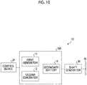
- Fig. 10 is a block diagram showing the configuration of a power generation system 1C according to a modification example of the second embodiment.
- the power generation system 1C includes a main generator 10A, a control device 20, a shaft generator 30, and a propeller 40.
- the main generator 10A has a first generator 11, a second generator 12, and a secondary battery 14. That is, the power generation system 1C is different from the power generation system 1B in that power is supplied to the ship using the two generators and the secondary battery.
- an operation to supply power to the interior of the ship using the first generator 11 and the shaft generator 30 and to charge the secondary battery 14 using the second generator 12 is the same as the operation shown in Fig. 8 excluding that the third generator 13 is made on standby, and thus, description thereof will not be repeated.
- Fig. 11 is a flowchart showing the operation of the power generation system 1C during normal sailing of the ship.
- Steps S701 to S706 are the same as Steps S301 to S306 shown in Fig. 5 , and thus, description thereof will not be repeated.
- the control device 20 operates the second generator 12 and the shaft generator 30 (Step S707).
- the control device 20 operates, for example, the second generator 12 under a high load (for example, 90% of the rated power) .
- the control device 20 makes the second generator 12 output power of 1350 kW. That is, the control device 20 operates the first generator 11 and the second generator 12 under a high load.
- the control device 20 operates the shaft generator 30 so as to enable charging of the secondary battery 14. Then, the control device 20 progresses to Step S708.
- the control device 20 supplies power of 1800 kW needed in the interior of the ship using the first generator 11 and the second generator 12 (Step S708). Then, the control device 20 progresses to Step S709.
- the control device 20 charges the secondary battery 14 using the first generator 11, the second generator 12, and the shaft generator 30 (Step S709).
- the secondary battery 14 is charged using surplus power out of power supplied from the first generator 11 and the second generator 12 to the interior of the ship and power output from the shaft generator 30 such that the ship can secure power needed during entry and departure.
- the control device 20 charges the secondary battery 14 using surplus power of 900 kW.
- the control device 20 may not operate the shaft generator 30 in Step S707.
- Steps S801 to S805 are the same as Steps S301 to S305 shown in Fig. 5 , and thus, description thereof will not be repeated.
- the control device 20 operates the second generator 12 (Step S806).
- the control device 20 operates, for example, the second generator 12 under a high load (for example, 90% of the rated power).
- the control device 20 makes the second generator 12 output power of 1350 kW. That is, the control device 20 operates the first generator 11 and the second generator 12 under a high load. Then, the control device 20 progresses to Step S807.
- the control device 20 supplies power of 1800 kW needed in the interior of the ship using the first generator 11 and the second generator 12 (Step S807). Then, the control device 20 progresses to Step S808.
- the control device 20 charges the secondary battery 14 using the first generator 11 and the second generator 12 (Step S808).
- the secondary battery 14 is charged using surplus power out of power supplied from the first generator 11 and the second generator 12 to the interior of the ship such that the ship can secure needed during entry and departure.
- the control device 20 charges the secondary battery 14 using surplus power of 900 kW. Then, the control device 20 progresses to Step S809.
- the control device 20 supplies power to the shaft generator 30 using the secondary battery 14 (Step S809).
- the control device 20 may skip Step S809.
- the use of the secondary battery enables reduction in the rated output of each of the generators compared to the related art, during normal sailing, it is possible to constantly operate the respective generators under a high load. Accordingly, in the embodiment, it is possible to suppress deterioration of the fuel efficiency of the power generation system during normal sailing of the ship.
Landscapes
- Engineering & Computer Science (AREA)
- Power Engineering (AREA)
- Chemical & Material Sciences (AREA)
- Combustion & Propulsion (AREA)
- Mechanical Engineering (AREA)
- Ocean & Marine Engineering (AREA)
- Control Of Eletrric Generators (AREA)
Description
- The present invention relates to a power generation system for ships.
- In a ship, such as a ferry, in order to supply power to inboard facilities, a plurality (for example, three) of generators are mounted in view of redundancy or needed maximum power, and each generator is operated such that an operation time becomes uniform. The maximum power is needed, for example, in a case where equipment, such as a bow thruster, is used during entry and departure. In this case, the three generators are operated under a high load. On the other hand, during normal sailing, power is supplied to the interior of the ship using two generators, and a remaining one generator is made on standby.
- Normally, since the generator is designed such that fuel efficiency is good with a rated output, no problem occurs with fuel efficiency during entry and departure. However, since the rated power of the generator is set based on power needed during entry and departure, two generators are operated under a low load (for example, 60% of the rated output) during normal sailing, and there is a problem in that fuel efficiency is deteriorated. For this reason, in order to operate the generators under a high load to restrain deterioration of fuel efficiency even during normal sailing, it is desirable to use a generator having a small rated output and a secondary battery in combination.
- PTL 1 discloses an electric motor system that includes a generator and a secondary battery, and can be operated with high efficiency even though requested torque and a requested rotation speed to a rotation output are changed.
- PTL 2 discloses a double-diesel generating set and lithium battery hybrid power ship structure which comprises an electric propulsion system. The electric propulsion system comprises two diesel generating sets, a lithium battery pack and an electric motor, wherein the two diesel generating sets, the lithium battery pack and the electric motor are connected with a direct-current bus, the electric motor is also connected with a propeller, the direct-current bus is also connected with shore power, and a power controller receives power signals of the electric motor and electrical charge status signals of the lithium battery pack and sends power control signals to the two diesel generating sets and a DC/DC convertor.
- PTL 3 discloses a ship and a power management method of the ship. The ship comprises: a power grid; at least one generator that is connected to the power grid and supplies electricity to the power grid; a high-capacity battery connected to the power grid, and charged by receiving the electricity from the power grid or discharged to supply power to the power grid; a plurality of load components connected to the power grid; and a controller for receiving generator load information from the at least one generator, sensing a voltage of the power grid to calculate a current load and an average load, and controlling the generator to bear the average load and the high-capacity battery to bear a difference load between the current load and the average load.
- PTL 4 discloses a power system for dynamic positioning of a vessel. The power system reduces fuel consumption, carbon buildup deposits and the risk of cylinder bore glazing while in combustion engine driven generators and provides an adequate protection against blackouts. The power system includes first and second combustion engine driven generators, a battery unit, and a converter unit arranged to provide power to the vessel from the battery unit. A first operational state of the power system in which the first combustion engine driven generator is arranged to deliver power to the vessel, and a second operational state, in which the first generator is subject to a fault, the second combustion engine driven generator arranged to deliver power to the vessel, and the converter unit is arranged to deliver power to the vessel during transition between the states.
-
- [PTL 1]
Japanese Unexamined Patent Application Publication No. 2003-189690 - [PTL 2]
CN 103 708 015 B - [PTL 3]
CN 107 636 928 A - [PTL 4]
US 2014/132064 A1 - However, in PTL 1, there is no description that deterioration of fuel efficiency is suppressed using the secondary battery. Accordingly, even though the electric motor system described in PTL 1 is applied to a ship, it is hard to suppress deterioration of the fuel efficiency of the generators during normal sailing of the ship.
- Therefore, an object of the invention is to suppress deterioration of fuel efficiency of generators during normal sailing using a secondary battery in a ship.
- Accordingly, there is provided a power generation system for ships as set out in independent claim 1. Advantageous developments are defined in the dependent claims.
- A power generation system for ships of the invention includes a plurality of generators that supply power to the interior of a ship, a secondary battery that stores power output from the plurality of generators and supplies the stored power to the interior of the ship, and a control device that supplies power to the ship using a first generator among the plurality of generators and the secondary battery during normal sailing of the ship. The control device charges the secondary battery so as to enable output of power equivalent to that of the first generator during entry and departure of the ship.
- With this structure, it is possible to provide power needed for the ship using a generator operated under a high load and the secondary battery. Accordingly, it is possible to improve the fuel efficiency of the generators.
- It is preferable that the secondary battery has capacity equal to or greater than 90% and equal to or less than 120% of a rated power of the first generator.
- With this structure, the secondary battery can be used in the same manner as the generators. Accordingly, it is possible to improve the fuel efficiency of the generators.
- It is preferable that, during normal sailing of the ship, the control device supplies power to the interior of the ship using the first generator and a second generator among the plurality of generators, and charges the secondary battery using a third generator among the plurality of generators.
- With this structure, during normal sailing, it is possible to charge the secondary battery while operating the respective generators under a high load. Accordingly, it is possible to improve fuel efficiency.
- It is preferable that, during normal sailing of the ship, the control device supplies power to the interior of the ship using the first generator and a second generator among the plurality of generators, and charges the secondary battery using surplus power out of power supplied to the interior of the ship.
- With this structure, during normal sailing, it is possible to charge the secondary battery while operating the respective generators under a high load. Accordingly, it is possible to improve fuel efficiency.
- It is preferable that the power generation system further includes a shaft generator provided in a rotary shaft of propulsion equipment.
- With this structure, it is possible to provide power needed for the ship using a generator operated under a high load, the secondary battery, and the shaft generator. Accordingly, it is possible to improve the fuel efficiency of the generators.
- It is preferable that, during normal sailing of the ship, the control device supplies power to the interior of the ship using the first generator and a second generator among the plurality of generators and charges the secondary battery using a third generator among the plurality of generators and the shaft generator.
- With this structure, during normal sailing, it is possible to charge the secondary battery while operating the respective generators under a high load. Accordingly, it is possible to improve the fuel efficiency of the generators.
- It is preferable that, during normal sailing of the ship, the control device supplies power to the interior of the ship using the first generator and the shaft generator, and charges the secondary battery using a second generator among the plurality of generators.
- With this structure, during normal sailing, it is possible to charge the secondary battery while operating the respective generators under a high load. Accordingly, it is possible to improve the fuel efficiency of the generators.
- It is preferable that, during normal sailing of the ship, the control device supplies power to the interior of the ship using the first generator and a second generator among the plurality of generators, charges the secondary battery using a third generator among the plurality of generators, and supplies power to the shaft generator using the secondary battery.
- With this structure, during normal sailing, it is possible to charge the secondary battery while operating the respective generators under a high load, and to supply to power to the shaft generator using the secondary battery. Accordingly, it is possible to improve the fuel efficiency of the generators. Since it is possible to support rotation of a propeller using the secondary battery, it is possible to reduce fuel consumption of a main engine.
- It is preferable that, during normal sailing of the ship, the control device supplies power to the interior of the ship using the first generator and a second generator among the plurality of generators, and charges the secondary battery using surplus power out of power supplied to the interior of the ship and the shaft generator.
- With this structure, during normal sailing, it is possible to charge the secondary battery while operating the respective generators under a high load. Accordingly, it is possible to improve the fuel efficiency of the generators.
- It is preferable that, during normal sailing of the ship, the control device supplies power to the interior of the ship using the first generator and a second generator among the plurality of generators, charges the secondary battery using surplus power out of power supplied to the interior of the ship, and supplies power to the shaft generator using the secondary battery.
- With this structure, during normal sailing, it is possible to charge the secondary battery while operating the respective generators under a high load. Accordingly, it is possible to improve the fuel efficiency of the generators.
-
-
Fig. 1 is a block diagram showing the configuration of a power generation system according to according to a first embodiment of the invention. -
Fig. 2 is a flowchart showing an example of the operation of the power generation system according to the first embodiment of the invention during entry and departure. -
Fig. 3 is a flowchart showing the operation of the power generation system according to the first embodiment of the invention during normal sailing of a ship. -
Fig. 4 is a block diagram showing the configuration of a power generation system according to a modification example of the first embodiment of the invention. -
Fig. 5 is a flowchart showing an example of the operation of the power generation system according to the modification example of the first embodiment of the invention during normal sailing of a ship. -
Fig. 6 is a block diagram showing the configuration of a power generation system according to a second embodiment of the invention. -
Fig. 7 is a flowchart showing an example of the operation of the power generation system of according to the second embodiment of the invention during normal sailing of a ship. -
Fig. 8 is a flowchart showing an example of the operation of the power generation system according to the second embodiment of the invention during normal sailing of the ship. -
Fig. 9 is a flowchart showing an example of the operation of the power generation system according to the second embodiment of the invention during normal sailing of the ship. -
Fig. 10 is a block diagram showing the configuration of a power generation system according to a modification example of the second embodiment of the invention. -
Fig. 11 is a flowchart showing an example of the operation of the power generation system according to the modification example of the second embodiment of the invention during normal sailing of a ship. -
Fig. 12 is a flowchart showing an example of the operation of the power generation system according to the modification example of the second embodiment of the invention during normal sailing of the ship. - A preferred embodiment of a power generation system for ships according to the invention will be described below in detail referring to the accompanying drawings. Note that the invention is not limited to the embodiment, and in a case where there are a plurality of embodiments, combinations of the embodiments still fall within the scope of the invention.
- The configuration of a power generation system according to a first embodiment of the invention will be described in connection with
Fig. 1. Fig. 1 is a block diagram showing the configuration of the power generation system according to the first embodiment of the invention. - As shown in
Fig. 1 , a power generation system 1 includes amain generator 10 and acontrol device 20. Themain generator 10 has afirst generator 11, asecond generator 12, athird generator 13, and asecondary battery 14. Although the power generation system 1 has three generators, this is for illustration, and is not intended to limit the invention. The power generation system 1 may have more generators. - The
first generator 11, thesecond generator 12, and thethird generator 13 are generators that are provided in the interior of a ship. Thefirst generator 11, thesecond generator 12, and thethird generator 13 supply power to respective facilities that are provided in the interior of the ship. It is preferable that thefirst generator 11, thesecond generator 12, and thethird generator 13 have the same rated power. In this case, the rated output of each of thefirst generator 11, thesecond generator 12, and thethird generator 13 is, for example, 1000 kW. Note that the rated output of each of thefirst generator 11, thesecond generator 12, and thethird generator 13 may be set according to power needed during entry and departure of the ship. - The
secondary battery 14 is provided in the interior of the ship and supplies power to respective facilities that are provided in the interior of the ship. Thesecondary battery 14 supplies, for example, power, which is insufficient for power supplied to the interior or the ship using one generator operated under a high load (for example, 90%) out of power needed in the interior of the ship, to the interior of the ship. Thesecondary battery 14 is charged using thefirst generator 11, thesecond generator 12, and thethird generator 13. The rated power of thesecondary battery 14 is, for example, 1500 kW in a case where the rated power of each of thefirst generator 11, thesecond generator 12, and thethird generator 13 is 1000 kW. That is, thesecondary battery 14 is a comparatively large-capacity secondary battery, and can output power as much as each of thefirst generator 11, thesecond generator 12, andthird generator 13. Specifically, it is preferable that thesecondary battery 14 can output power equal to or greater than 90% and equal to or less than 120% of the rated output of each of the generators. An upper limit of the capacity of thesecondary battery 14 is decided in view of the cycle characteristic of thesecondary battery 14. For example, the upper limit of the capacity of thesecondary battery 14 is decided such that power equal to or greater than 90% of the rated power of thethird generator 13 can be output from thefirst generator 11 even though the capacity of thesecondary battery 14 is deteriorated to 80%. For this reason, thesecondary battery 14 can be used instead of thefirst generator 11, thesecond generator 12, and thethird generator 13. - The
control device 20 controls thefirst generator 11, thesecond generator 12, thethird generator 13, and thesecondary battery 14. Specifically, thecontrol device 20 expands and executes a program stored in a storage device (not shown), thereby controlling thefirst generator 11, thesecond generator 12, thethird generator 13, and thesecondary battery 14. Thecontrol device 20 can be implemented by an electronic circuit including a central processing unit (CPU), or the like. - Next, the operation of the power generation system 1 shown in
Fig. 1 will be described referring toFigs. 2 and3 .Fig. 2 is a flowchart showing the operation of the power generation system 1 during entry and departure of the ship.Fig. 3 is a flowchart showing the operation of the power generation system 1 during normal sailing of the ship. In the following description, although an example where power needed during entry and departure of the ship is 4500 kW, and power needed during normal sailing is 1800 kW will be described, the invention is not limited thereto. - First, the operation of the power generation system 1 during entry and departure of the ship will be described in connection with
Fig. 2 . Thecontrol device 20 operates thefirst generator 11, thesecond generator 12, and the third generator 13 (Step S101). Here, thecontrol device 20 operates thefirst generator 11, thesecond generator 12, and thethird generator 13 with the rated output. It is assumed that the rated power of each of thefirst generator 11, thesecond generator 12, and thethird generator 13 is 1000 kW. That is, thecontrol device 20 makes thefirst generator 11, thesecond generator 12, and thethird generator 13 output power of 3000 kW. Then, thecontrol device 20 progresses to Step S102. - The
control device 20 operates the secondary battery 14 (Step S102). Here, thesecondary battery 14 is charged so as to enable output of power as much as each of thefirst generator 11, thesecond generator 12, and thethird generator 13 during normal sailing. Specifically, thecontrol device 20 makes thesecondary battery 14 output power of 1500 kW. Then, thecontrol device 20 progresses to Step S103. - The
control device 20 supplies power of 4500 kW to the interior of the ship using thefirst generator 11, thesecond generator 12, thethird generator 13, and the secondary battery 14 (Step S103). - Next, the operation of the power generation system 1 during normal sailing of the ship will be described in connection with
Fig. 3 . - First, the
control device 20 operates the first generator 11 (Step S201). Here, thecontrol device 20 operates, for example, thefirst generator 11 under a high load (for example, 90% of the rated output), and makes thesecond generator 12 and thethird generator 13 on standby. Specifically, in a case where the rated power of the first generator is 1000 kW, thecontrol device 20 makes thefirst generator 11 output power of 900 kW. Then, thecontrol device 20 progresses to Step S202. - The
control device 20 operates the secondary battery 14 (Step S202). Here, thecontrol device 20 makes power needed in the interior of the ship be output. For example, since power needed in the interior of the ship is 1800 kW, and thefirst generator 11 outputs power of 900 kW, thecontrol device 20 makes thesecondary battery 14 output insufficient power of 900 kW. Then, thecontrol device 20 progresses to Step S203. - The
control device 20 supplies power of 1800 kW to the interior of the ship using thefirst generator 11 and the secondary battery 14 (Step S203). Then, thecontrol device 20 progresses to Step S204. - Next, the
control device 20 confirms an amount of charge of the secondary battery 14 (Step S204). Then, thecontrol device 20 progresses to Step S205. - In a case where the
secondary battery 14 does not need charging (in Step S205, "No"), thecontrol device 20 returns to Step S203. That is, in a case where the amount of charge of thesecondary battery 14 is sufficient, power is continued to be supplied to the interior of the ship using thefirst generator 11 and thesecondary battery 14. On the other hand, in a case where thesecondary battery 14 needs charging (in Step S205, "Yes"), thecontrol device 20 progresses to Step S206. A case where thesecondary battery 14 needs charging means, for example, a case where power equivalent to that of each of the generators cannot be output during entry and departure. - The
control device 20 stops the secondary battery (Step S206). Then, thecontrol device 20 progresses to Step S207. - The
control device 20 operates thesecond generator 12 and the third generator 13 (Step S207). Here, thecontrol device 20 operates thesecond generator 12 and thethird generator 13 under a high load (for example, 90% of the rated power). Specifically, in a case where the rated power of each of thesecond generator 12 and thethird generator 13 is 1000 kW, thecontrol device 20 makes thesecond generator 12 and thethird generator 13 output power of 900 kW. That is, thecontrol device 20 operates the three generators of thefirst generator 11, thesecond generator 12, and thethird generator 13 under a high load. Then, thecontrol device 20 progresses to Step S208. - The
control device 20 supplies power of 1800 kW needed in the interior of the ship using thefirst generator 11 and the second generator 12 (Step S208). Then, thecontrol device 20 progresses to Step S209. - The
control device 20 charges thesecondary battery 14 using the third generator 13 (Step S209). Here, thecontrol device 20 charges thesecondary battery 14 using thethird generator 13 such that the ship can secure power needed during entry and departure. Specifically, in a case where the rated power of each of thefirst generator 11, thesecond generator 12, and thethird generator 13 is 1000 kW, thesecondary battery 14 is charged so as to enable output of power of 1500 kW. Since thefirst generator 11, thesecond generator 12, and thethird generator 13 have the same rated output, thefirst generator 11, thesecond generator 12, and thethird generator 13 are operated in a rotating manner such that an operation rate becomes the same. - Next, a modification example of the power generation system 1 according to the first embodiment will be described referring to
Fig. 4. Fig. 4 is a block diagram showing the configuration of apower generation system 1A according to a modification example of the first embodiment. - As shown in
Fig. 4 , thepower generation system 1A includes amain generator 10A and acontrol device 20. Themain generator 10A has afirst generator 11, asecond generator 12, and asecondary battery 14. That is, thepower generation system 1A is different from the power generation system 1 in that power is supplied to a ship using the two generators and the secondary battery. In this case, it is assumed that the rated output of each of thefirst generator 11 and thesecond generator 12 is 1500 kW in a case where power needed during entry and departure of the ship is 4500 kW. - Next, the operation of the
power generation system 1A shown inFig. 4 will be described referring toFig. 5. Fig. 5 is a flowchart showing the operation of thepower generation system 1A during normal sailing of the ship. The operation during entry and departure is the same as in the power generation system 1, and thus, description thereof will not be repeated. In the following description, an example where power needed during entry and departure of the ship is 4500 kW, and power needed during normal sailing is 1800 kW will be described. - The
control device 20 operates the first generator 11 (Step S301). Here, thecontrol device 20 operates, for example, thefirst generator 11 under a high load (for example, 90% of the rated power), and makes thesecond generator 12 on standby. Specifically, in a case where the rated power of the first generator is 1500 kW, thecontrol device 20 makes thefirst generator 11 output power of 1350 kW. Then, thecontrol device 20 progresses to Step S302. - The
control device 20 operates the secondary battery 14 (Step S302). Here, thecontrol device 20 makes power needed in the interior of the ship be output. For example, since power needed in the interior of the ship is 1800 kW, and thefirst generator 11 outputs power of 1350 kW, thecontrol device 20 makes thesecondary battery 14 output insufficient power of 450 kW. Then, thecontrol device 20 progresses to Step S303. - The
control device 20 supplies power of 1800 kW to the interior of the ship using thefirst generator 11 and the secondary battery 14 (Step S303). Then, thecontrol device 20 progresses to Step S304. - Next, the
control device 20 confirms an amount of charge of the secondary battery 14(Step S304). Then, thecontrol device 20 progresses to Step S305. - In a case where the
secondary battery 14 does not need charging (in Step S305, "No"), thecontrol device 20 returns to Step S303. On the other hand, in a case where thesecondary battery 14 needs charging (in Step S305, "Yes"), thecontrol device 20 progresses to Step S306. - The
control device 20 stops the secondary battery 14 (Step S306). Then, thecontrol device 20 progresses to Step S307. - The
control device 20 operates the second generator 12 (Step S307). Here, thecontrol device 20 operates, for example, thesecond generator 12 under a high load (for example, 90% of the rated power). Specifically, in a case where the rated power of thesecond generator 12 is 1500 kW, thecontrol device 20 makes thesecond generator 12 output power of 1350 kW. That is, thecontrol device 20 operates thefirst generator 11 and thesecond generator 12 under a high load. Then, thecontrol device 20 progresses to Step S308. - The
control device 20 supplies power of 1800 kW needed in the interior of the ship using thefirst generator 11 and the second generator 12 (Step S308). Then, thecontrol device 20 progresses to Step S309. - The
control device 20 charges thesecondary battery 14 using thefirst generator 11 and the second generator 12 (Step S309). Here, thesecondary battery 14 is charged using surplus power out of power supplied from thefirst generator 11 and thesecond generator 12 to the interior of the ship such that the ship can secure power needed during entry and departure. Specifically, since power needed in the interior of the ship is 1800 kW, and thefirst generator 11 and thesecond generator 12 output power of 2700 kW in total, thecontrol device 20 charges thesecondary battery 14 using surplus power of 900 kW. - As described above, in the embodiment, since the use of the secondary battery enables reduction in the rated output of each of the generators compared to the related art, during normal sailing, it is possible to constantly operate the respective generators under a high load. Accordingly, in the embodiment, it is possible to suppress deterioration of the fuel efficiency of the power generation system during normal sailing of the ship.
- In the embodiment, although the main engine is powered by a diesel engine, the main engine may be powered electrically. In a case where the main engine is powered through electric drive, a plurality of generators are further mounted, whereby the embodiment can be applied. With this, even though the main engine is electrically driven, it is possible to operate the respective generators under a high load while providing power using the secondary battery. Accordingly, even though the main engine is electrically driven, it is possible to suppress deterioration of fuel efficiency.
- A
power generation system 1B according to a second embodiment of the invention will be described in connection withFig. 6. Fig. 6 is a block diagram showing the configuration of thepower generation system 1B according to the second embodiment of the invention. - As shown in
Fig. 6 , thepower generation system 1B includes amain generator 10, acontrol device 20, ashaft generator 30, and apropeller 40. - The
shaft generator 30 is a rotary generator provided in a rotary shaft of propulsion equipment. Specifically, theshaft generator 30 generates power using rotation of a shaft for transmitting power of a main engine to thepropeller 40. Theshaft generator 30 supplies generated power to the interior of the ship or charges thesecondary battery 14 using generated power during normal sailing of the ship. Theshaft generator 30 does not normally supply power to the interior of the ship and does not charge thesecondary battery 14 during entry and departure. In a case where power to be supplied to the interior of the ship is insufficient, or the like, theshaft generator 30 may supply power to the interior of the ship. - Next, the operation of the
power generation system 1B shown inFig. 6 will be described referring toFig. 7. Fig. 7 is a flowchart showing the operation of thepower generation system 1B during normal sailing of the ship. The operation shown inFig. 7 is an operation to supply power to the interior of the ship using thefirst generator 11 and thesecond generator 12, and to charge thesecondary battery 14 using thethird generator 13 and theshaft generator 30 in a case where thesecondary battery 14 needs charging. The operation during entry and departure is the same as in the power generation system 1, and thus, description thereof will not be repeated. In the following description, an example where power needed during entry and departure of the ship is 4500 kW, and power needed during normal sailing is 1800 kW will be described. - First, the
control device 20 operates the first generator 11 (Step S401). Here, thecontrol device 20 operates, for example, thefirst generator 11 under a high load (for example, 90% of the rated output), and makes thesecond generator 12 and thethird generator 13 on standby. Then, thecontrol device 20 progresses to Step S402. - The
control device 20 operates the secondary battery 14 (Step S402). Here, thecontrol device 20 makes power needed in the interior of the ship be output. Then, thecontrol device 20 progresses to Step S403. - The
control device 20 supplies power of 1800 kW to the interior of the ship using thefirst generator 11 and the secondary battery 14 (Step S403). Here, thecontrol device 20 may supply power to the interior of the ship using theshaft generator 30. Then, thecontrol device 20 progresses to Step S404. - Next, the
control device 20 confirms an amount of charge of the secondary battery 14 (Step S404). Then, thecontrol device 20 progresses to Step S405. - In a case where the
secondary battery 14 does not need charging (in Step S405, "No"), thecontrol device 20 returns to Step S403. On the other hand, in a case where thesecondary battery 14 needs charging (in Step S405, "Yes"), thecontrol device 20 progresses to Step S406. A case where thesecondary battery 14 needs charging means, for example, a case where power equivalent to that of each of the generators cannot be output during entry and departure. - The
control device 20 stops the secondary battery (Step S406). Then, thecontrol device 20 progresses to Step S407. - The
control device 20 operates thesecond generator 12, thethird generator 13, and the shaft generator 30 (Step S407) . Here, thecontrol device 20 makes thesecond generator 12 output power needed in the interior of the ship. Then, thecontrol device 20 progresses to Step S408. - The
control device 20 supplies power of 1800 kW needed in the interior of the ship using thefirst generator 11 and the second generator 12 (Step S408). Then, thecontrol device 20 progresses to Step S409. - The
control device 20 charges thesecondary battery 14 using thethird generator 13 and the shaft generator 30 (Step S409). Here, thecontrol device 20 charges thesecondary battery 14 using thethird generator 13 and theshaft generator 30 such that the ship can secure power needed during entry and departure. In a case where thesecondary battery 14 can be sufficiently charged only using thethird generator 13 or theshaft generator 30, thecontrol device 20 may operate only one of thethird generator 13 and theshaft generator 30 in Step S407. - Next, an operation of the
power generation system 1B shown inFig. 6 different fromFig. 7 will be described referring toFig. 8. Fig. 8 is a flowchart showing an operation of thepower generation system 1B different fromFig. 7 during normal sailing of the ship. Specifically, the operation shown inFig. 8 is an operation to supply power to the interior of the ship using thefirst generator 11 and theshaft generator 30 and charge thesecondary battery 14 using thesecond generator 12 in a case where thesecondary battery 14 needs charging. - Steps S501 to S506 are the same as Steps S401 to S406 shown in
Fig. 7 , and thus, description thereof will not be repeated. - The
control device 20 operates thesecond generator 12 and the shaft generator 30 (Step S507). Here, thecontrol device 20 makes theshaft generator 30 output power needed in the interior of the ship. For example, since power needed in the interior of the ship is 1800 kW, and thefirst generator 11 outputs power of 900 kW, thecontrol device 20 makesshaft generator 30 output insufficient power of 900 kW. In the processing ofFig. 8 , thethird generator 13 is brought into a standby state. - The
control device 20 supplies power of 1800 kW needed in the interior of the ship using thefirst generator 11 and the shaft generator 30 (Step S508). Then, thecontrol device 20 progresses to Step S509. - The
control device 20 charges thesecondary battery 14 using the second generator 12 (Step S509). Here, thecontrol device 20 charges thesecondary battery 14 using thesecond generator 12 such that the ship can secure power needed during entry and departure. Specifically, in a case where the rated power of each of thefirst generator 11, thesecond generator 12, and thethird generator 13 is 1000 kW, thesecondary battery 14 is charged so as to enable output of power of 1500 kW. - Next, an operation of the
power generation system 1B shown inFig. 6 different fromFigs. 7 and8 will be described referring toFig. 9. Fig. 9 is a flowchart showing an operation of thepower generation system 1B during normal sailing of the ship different fromFigs. 7 and8 . Specifically, the operation shown inFig. 9 is an operation to supply power to the interior of the ship using thefirst generator 11 and thesecond generator 12, to charge thesecondary battery 14 using thethird generator 13, and to support the rotation of thepropeller 40 using thesecondary battery 14. - Steps S601 to S605 are the same as Steps S401 to S405 shown in
Fig. 7 , and thus, description thereof will not be repeated. - The
control device 20 operates thesecond generator 12 and the third generator 13 (Step S606). Here, thecontrol device 20 operates thesecond generator 12 and thethird generator 13 under a high load (for example, 90% of the rated power). Specifically, in a case where the rated power of each of thesecond generator 12 and thethird generator 13 is 1000 kW, thecontrol device 20 makes thesecond generator 12 and thethird generator 13 output power of 900 kW. That is, thecontrol device 20 operates the three generators of thefirst generator 11, thesecond generator 12, and thethird generator 13 under a high load. Then, thecontrol device 20 progresses to Step S607. - The
control device 20 supplies power of 1800 kW needed in the interior of the ship using thefirst generator 11 and the second generator 12 (Step S607). Then, thecontrol device 20 progresses to Step S608. - The
control device 20 charges thesecondary battery 14 using the third generator 13 (Step S608). Here, thecontrol device 20 charges thesecondary battery 14 to such an extent as to support the rotation of thepropeller 40. Here, in a case thesecondary battery 14 is charged with power sufficient for supporting theshaft generator 30, thecontrol device 20 may skip Step S608. Then, thecontrol device 20 progresses to Step S609. - The
control device 20 supplies power to theshaft generator 30 using the secondary battery 14 (Step S609). With this, power is supplied from theshaft generator 30 to rotational power of thepropeller 40, and the rotation of thepropeller 40 is supported. - Next, a modification example of the
power generation system 1B according to the second embodiment will be described referring toFig. 10. Fig. 10 is a block diagram showing the configuration of apower generation system 1C according to a modification example of the second embodiment. - As shown in
Fig. 10 , thepower generation system 1C includes amain generator 10A, acontrol device 20, ashaft generator 30, and apropeller 40. Themain generator 10A has afirst generator 11, asecond generator 12, and asecondary battery 14. That is, thepower generation system 1C is different from thepower generation system 1B in that power is supplied to the ship using the two generators and the secondary battery. In a case where thesecondary battery 14 needs charging, an operation to supply power to the interior of the ship using thefirst generator 11 and theshaft generator 30 and to charge thesecondary battery 14 using thesecond generator 12 is the same as the operation shown inFig. 8 excluding that thethird generator 13 is made on standby, and thus, description thereof will not be repeated. - The operation of the
power generation system 1C shown inFig. 10 will be described referring toFig. 11. Fig. 11 is a flowchart showing the operation of thepower generation system 1C during normal sailing of the ship. - Steps S701 to S706 are the same as Steps S301 to S306 shown in
Fig. 5 , and thus, description thereof will not be repeated. - The
control device 20 operates thesecond generator 12 and the shaft generator 30 (Step S707). Here, thecontrol device 20 operates, for example, thesecond generator 12 under a high load (for example, 90% of the rated power) . Specifically, in a case where the rated power of thesecond generator 12 is 1500 kW, thecontrol device 20 makes thesecond generator 12 output power of 1350 kW. That is, thecontrol device 20 operates thefirst generator 11 and thesecond generator 12 under a high load. Thecontrol device 20 operates theshaft generator 30 so as to enable charging of thesecondary battery 14. Then, thecontrol device 20 progresses to Step S708. - The
control device 20 supplies power of 1800 kW needed in the interior of the ship using thefirst generator 11 and the second generator 12 (Step S708). Then, thecontrol device 20 progresses to Step S709. - The
control device 20 charges thesecondary battery 14 using thefirst generator 11, thesecond generator 12, and the shaft generator 30 (Step S709). Here, thesecondary battery 14 is charged using surplus power out of power supplied from thefirst generator 11 and thesecond generator 12 to the interior of the ship and power output from theshaft generator 30 such that the ship can secure power needed during entry and departure. Specifically, since power needed in the interior of the ship is 1800 kW, and thefirst generator 11 and thesecond generator 12 output power of 2700 kW in total, thecontrol device 20 charges thesecondary battery 14 using surplus power of 900 kW. In a case where the secondary battery can be sufficiently charge using thefirst generator 11 and thesecond generator 12, thecontrol device 20 may not operate theshaft generator 30 in Step S707. - Next, an operation of the
power generation system 1C shown inFig. 10 different fromFig. 11 will be described referring toFig. 12 . - Steps S801 to S805 are the same as Steps S301 to S305 shown in
Fig. 5 , and thus, description thereof will not be repeated. - The
control device 20 operates the second generator 12 (Step S806). Here, thecontrol device 20 operates, for example, thesecond generator 12 under a high load (for example, 90% of the rated power). Specifically, in a case where the rated power of thesecond generator 12 is 1500 kW, thecontrol device 20 makes thesecond generator 12 output power of 1350 kW. That is, thecontrol device 20 operates thefirst generator 11 and thesecond generator 12 under a high load. Then, thecontrol device 20 progresses to Step S807. - The
control device 20 supplies power of 1800 kW needed in the interior of the ship using thefirst generator 11 and the second generator 12 (Step S807). Then, thecontrol device 20 progresses to Step S808. - The
control device 20 charges thesecondary battery 14 using thefirst generator 11 and the second generator 12 (Step S808). Here, thesecondary battery 14 is charged using surplus power out of power supplied from thefirst generator 11 and thesecond generator 12 to the interior of the ship such that the ship can secure needed during entry and departure. Specifically, since power needed in the interior of the ship is 1800 kW, and thefirst generator 11 and thesecond generator 12 output power of 2700 kW in total, thecontrol device 20 charges thesecondary battery 14 using surplus power of 900 kW. Then, thecontrol device 20 progresses to Step S809. - The
control device 20 supplies power to theshaft generator 30 using the secondary battery 14 (Step S809). Thecontrol device 20 may skip Step S809. - As described above, in the embodiment, since the use of the secondary battery enables reduction in the rated output of each of the generators compared to the related art, during normal sailing, it is possible to constantly operate the respective generators under a high load. Accordingly, in the embodiment, it is possible to suppress deterioration of the fuel efficiency of the power generation system during normal sailing of the ship.
- In the embodiment, during normal sailing, it is possible to supply power to the interior of the ship or to charge the secondary battery using the respective generators and the shaft generator. In the embodiment, it is possible to further suppress deterioration of the fuel efficiency of the power generation system during normal sailing of the ship. In the embodiment, it is possible to reduce the fuel consumption of the main engine.
-
- 1, 1A, 1B, 1C: power generation system
- 10, 10A: main generator
- 11: first generator
- 12: second generator
- 13: third generator
- 14: secondary battery
- 30: shaft generator
- 40: propeller
Claims (8)
- A power generation system (1B, 1C) for ships needing a maximum power for a bow thruster during entry and departure, comprising:a plurality of generators (11, 12, 13) that supply power to an interior of a ship;a secondary battery (14) that stores power output from the plurality of generators (11, 12, 13) and supplies the stored power to the interior of the ship;a control device that, during normal sailing of the ship, causes a first generator (11) among the plurality of generators (11, 12, 13) and the secondary battery (14) to supply power to the interior of the ship, and causes the secondary battery (14) to charge so as to enable output power equivalent to that of the first generator (11) during entry and departure, anda shaft generator (30) provided in a rotary shaft of propulsion equipment of the ship, whereinthe propulsion equipment is a main engine of the ship, and the rotary shaft transmits power of the main engine to a propeller (40).
- The power generation system (1B, 1C) for ships according to claim 1,
wherein the secondary battery (14) has capacity equal to or greater than 90% and equal to or less than 120% of a rated power of the first generator (11). - The power generation system (1B) for ships according to claim 1 or 2,
wherein, during normal sailing of the ship, the control device causes the first generator (11) and a second generator (12) among the plurality of generators (11, 12, 13) to supply power to the interior of the ship and causes a third generator (13) among the plurality of generators (11, 12, 13) and the shaft generator (30) to charge the secondary battery. - The power generation system (1B) for ships according to claim 1 or 2,
wherein, during normal sailing of the ship, the control device causes the first generator (11) and the shaft generator (30) to supply power to the interior of the ship, and causes a second generator (12) among the plurality of generators (11, 12, 13) to charge the secondary battery (14). - The power generation system (1B) for ships according to claim 1 or 2,
wherein, during normal sailing of the ship, the control device causes the first generator (11) and a second generator (12) among the plurality of generators (11, 12, 13) to supply power to the interior of the ship, causes a third generator (13) among the plurality of generators (11, 12, 13) to charge the secondary battery (14), and causes the secondary battery (14) to supply power to the shaft generator (30). - The power generation system (1C) for ships according to claim 1 or 2,
wherein, during normal sailing of the ship, the control device causes the first generator (11) and a second generator (12) among the plurality of generators (11, 12) to supply power to the interior of the ship, and causes surplus power out of power supplied to the interior of the ship and the shaft generator (30) to charge the secondary battery (14). - The power generation system (1C) for ships according to claim 1 or 2,
wherein, during normal sailing of the ship, the control device causes the first generator (11) and a second generator (12) among the plurality of generators (11, 12) to supply power to the interior of the ship, causes surplus power out of power supplied to the interior of the ship to charge the secondary battery (14), and causes the secondary battery (14) to supply power to the shaft generator (30). - The power generation system (1B) for ships according to claim 1, wherein
the ships further comprise a bow thruster.
Applications Claiming Priority (2)
| Application Number | Priority Date | Filing Date | Title |
|---|---|---|---|
| JP2018029088A JP7158156B2 (en) | 2018-02-21 | 2018-02-21 | ship power generation system |
| PCT/JP2018/043058 WO2019163228A1 (en) | 2018-02-21 | 2018-11-21 | Power generation system for ships |
Publications (3)
| Publication Number | Publication Date |
|---|---|
| EP3733502A1 EP3733502A1 (en) | 2020-11-04 |
| EP3733502A4 EP3733502A4 (en) | 2021-03-31 |
| EP3733502B1 true EP3733502B1 (en) | 2022-04-06 |
Family
ID=67687629
Family Applications (1)
| Application Number | Title | Priority Date | Filing Date |
|---|---|---|---|
| EP18906952.9A Active EP3733502B1 (en) | 2018-02-21 | 2018-11-21 | Power generation system for ships |
Country Status (5)
| Country | Link |
|---|---|
| EP (1) | EP3733502B1 (en) |
| JP (1) | JP7158156B2 (en) |
| KR (1) | KR102401148B1 (en) |
| CN (1) | CN111527026B (en) |
| WO (1) | WO2019163228A1 (en) |
Families Citing this family (1)
| Publication number | Priority date | Publication date | Assignee | Title |
|---|---|---|---|---|
| US20250171126A1 (en) * | 2023-11-28 | 2025-05-29 | Stewart & Stevenson Llc | Marine hybrid vessel power management |
Family Cites Families (13)
| Publication number | Priority date | Publication date | Assignee | Title |
|---|---|---|---|---|
| JP2003189690A (en) | 2001-12-20 | 2003-07-04 | Toyota Motor Corp | Motor system with multiple motors |
| JP4421344B2 (en) * | 2004-03-26 | 2010-02-24 | 新潟原動機株式会社 | Ship drive control method |
| JP5333965B2 (en) * | 2008-11-13 | 2013-11-06 | 西芝電機株式会社 | Ship energy system |
| JP5357526B2 (en) * | 2008-12-10 | 2013-12-04 | ジャパンマリンユナイテッド株式会社 | Ship power equipment and operation method thereof |
| JP2011087348A (en) * | 2009-10-13 | 2011-04-28 | Ryoukou Enginering Kk | Power distribution system for ship |
| JP5737969B2 (en) * | 2011-01-28 | 2015-06-17 | 三菱重工業株式会社 | Ship power control method and ship power control system |
| BR112014001093A2 (en) * | 2011-07-18 | 2017-02-14 | Abb As | boat power system |
| JP5767059B2 (en) * | 2011-08-22 | 2015-08-19 | 三井造船株式会社 | Electric propulsion ship |
| KR101310312B1 (en) * | 2012-07-04 | 2013-09-23 | 주식회사 조앤파트너스 | Reorganizing method of power supply system for ship |
| CN103708015B (en) * | 2013-12-18 | 2016-06-08 | 上海海事大学 | A kind of double; two diesel generating set and lithium battery hybrid power boats and ships structure and control method |
| KR101680321B1 (en) * | 2015-03-20 | 2016-11-28 | 삼성중공업 주식회사 | ESS control apparatus |
| KR101645703B1 (en) * | 2015-04-17 | 2016-08-04 | 삼성중공업 주식회사 | a ship including a battery |
| DK3297122T3 (en) * | 2015-05-13 | 2022-05-02 | Samsung Heavy Ind | Ship and electricity management method therefor |
-
2018
- 2018-02-21 JP JP2018029088A patent/JP7158156B2/en active Active
- 2018-11-21 CN CN201880084973.4A patent/CN111527026B/en active Active
- 2018-11-21 WO PCT/JP2018/043058 patent/WO2019163228A1/en not_active Ceased
- 2018-11-21 EP EP18906952.9A patent/EP3733502B1/en active Active
- 2018-11-21 KR KR1020207019097A patent/KR102401148B1/en active Active
Also Published As
| Publication number | Publication date |
|---|---|
| WO2019163228A1 (en) | 2019-08-29 |
| KR20200088481A (en) | 2020-07-22 |
| EP3733502A4 (en) | 2021-03-31 |
| KR102401148B1 (en) | 2022-05-23 |
| CN111527026A (en) | 2020-08-11 |
| EP3733502A1 (en) | 2020-11-04 |
| JP2019142376A (en) | 2019-08-29 |
| JP7158156B2 (en) | 2022-10-21 |
| CN111527026B (en) | 2022-08-26 |
Similar Documents
| Publication | Publication Date | Title |
|---|---|---|
| EP3412558B1 (en) | Ship power system | |
| US11932408B2 (en) | Hybrid propulsion assembly for aircraft | |
| JP5333965B2 (en) | Ship energy system | |
| CN102812614B (en) | Generating equipment | |
| US20220177144A1 (en) | Hybrid propulsion unit for an aircraft | |
| US11554875B2 (en) | Method of electrically powering an electricity network, and an electrical architecture | |
| US12071250B2 (en) | Electric architecture for hybrid propulsion | |
| CN110249494A (en) | Power distribution system for moving body | |
| JP2009262671A (en) | Control system of vessel electric propulsion system | |
| EP3733502B1 (en) | Power generation system for ships | |
| CN116325404A (en) | Energy supply systems for marine vehicles | |
| JP6202329B2 (en) | Hybrid electric propulsion device | |
| CN101652311B (en) | Crane device | |
| CN106103331B (en) | Crane equipment, power supplier unit and remodeling method | |
| KR20120095148A (en) | Power management system in ship having mass-storage charging apparatus | |
| EP4053067A1 (en) | Crane device for ships | |
| KR102704724B1 (en) | Electric power control system for ship using hydrogen fuel cell | |
| KR20220129186A (en) | ship position control system | |
| Alho et al. | DC Voltage Level–Based Power Supply Prioritization in Multi–Inverter System: Marine Use Case | |
| US8457819B2 (en) | Computer readable medium for operating a vessel | |
| WO2025262640A1 (en) | Energy storage |
Legal Events
| Date | Code | Title | Description |
|---|---|---|---|
| STAA | Information on the status of an ep patent application or granted ep patent |
Free format text: STATUS: THE INTERNATIONAL PUBLICATION HAS BEEN MADE |
|
| PUAI | Public reference made under article 153(3) epc to a published international application that has entered the european phase |
Free format text: ORIGINAL CODE: 0009012 |
|
| STAA | Information on the status of an ep patent application or granted ep patent |
Free format text: STATUS: REQUEST FOR EXAMINATION WAS MADE |
|
| 17P | Request for examination filed |
Effective date: 20200730 |
|
| AK | Designated contracting states |
Kind code of ref document: A1 Designated state(s): AL AT BE BG CH CY CZ DE DK EE ES FI FR GB GR HR HU IE IS IT LI LT LU LV MC MK MT NL NO PL PT RO RS SE SI SK SM TR |
|
| AX | Request for extension of the european patent |
Extension state: BA ME |
|
| A4 | Supplementary search report drawn up and despatched |
Effective date: 20210225 |
|
| RIC1 | Information provided on ipc code assigned before grant |
Ipc: B63H 21/20 20060101ALI20210219BHEP Ipc: B63J 99/00 20090101AFI20210219BHEP Ipc: B63J 3/02 20060101ALI20210219BHEP Ipc: H02P 9/04 20060101ALI20210219BHEP |
|
| DAV | Request for validation of the european patent (deleted) | ||
| DAX | Request for extension of the european patent (deleted) | ||
| GRAP | Despatch of communication of intention to grant a patent |
Free format text: ORIGINAL CODE: EPIDOSNIGR1 |
|
| STAA | Information on the status of an ep patent application or granted ep patent |
Free format text: STATUS: GRANT OF PATENT IS INTENDED |
|
| INTG | Intention to grant announced |
Effective date: 20211026 |
|
| GRAS | Grant fee paid |
Free format text: ORIGINAL CODE: EPIDOSNIGR3 |
|
| GRAA | (expected) grant |
Free format text: ORIGINAL CODE: 0009210 |
|
| STAA | Information on the status of an ep patent application or granted ep patent |
Free format text: STATUS: THE PATENT HAS BEEN GRANTED |
|
| AK | Designated contracting states |
Kind code of ref document: B1 Designated state(s): AL AT BE BG CH CY CZ DE DK EE ES FI FR GB GR HR HU IE IS IT LI LT LU LV MC MK MT NL NO PL PT RO RS SE SI SK SM TR |
|
| REG | Reference to a national code |
Ref country code: GB Ref legal event code: FG4D |
|
| REG | Reference to a national code |
Ref country code: CH Ref legal event code: EP |
|
| REG | Reference to a national code |
Ref country code: AT Ref legal event code: REF Ref document number: 1481107 Country of ref document: AT Kind code of ref document: T Effective date: 20220415 |
|
| REG | Reference to a national code |
Ref country code: IE Ref legal event code: FG4D |
|
| REG | Reference to a national code |
Ref country code: DE Ref legal event code: R096 Ref document number: 602018033622 Country of ref document: DE |
|
| REG | Reference to a national code |
Ref country code: FI Ref legal event code: FGE |
|
| REG | Reference to a national code |
Ref country code: LT Ref legal event code: MG9D |
|
| REG | Reference to a national code |
Ref country code: NL Ref legal event code: MP Effective date: 20220406 |
|
| REG | Reference to a national code |
Ref country code: AT Ref legal event code: MK05 Ref document number: 1481107 Country of ref document: AT Kind code of ref document: T Effective date: 20220406 |
|
| PG25 | Lapsed in a contracting state [announced via postgrant information from national office to epo] |
Ref country code: NL Free format text: LAPSE BECAUSE OF FAILURE TO SUBMIT A TRANSLATION OF THE DESCRIPTION OR TO PAY THE FEE WITHIN THE PRESCRIBED TIME-LIMIT Effective date: 20220406 |
|
| PG25 | Lapsed in a contracting state [announced via postgrant information from national office to epo] |
Ref country code: SE Free format text: LAPSE BECAUSE OF FAILURE TO SUBMIT A TRANSLATION OF THE DESCRIPTION OR TO PAY THE FEE WITHIN THE PRESCRIBED TIME-LIMIT Effective date: 20220406 Ref country code: PT Free format text: LAPSE BECAUSE OF FAILURE TO SUBMIT A TRANSLATION OF THE DESCRIPTION OR TO PAY THE FEE WITHIN THE PRESCRIBED TIME-LIMIT Effective date: 20220808 Ref country code: NO Free format text: LAPSE BECAUSE OF FAILURE TO SUBMIT A TRANSLATION OF THE DESCRIPTION OR TO PAY THE FEE WITHIN THE PRESCRIBED TIME-LIMIT Effective date: 20220706 Ref country code: LT Free format text: LAPSE BECAUSE OF FAILURE TO SUBMIT A TRANSLATION OF THE DESCRIPTION OR TO PAY THE FEE WITHIN THE PRESCRIBED TIME-LIMIT Effective date: 20220406 Ref country code: HR Free format text: LAPSE BECAUSE OF FAILURE TO SUBMIT A TRANSLATION OF THE DESCRIPTION OR TO PAY THE FEE WITHIN THE PRESCRIBED TIME-LIMIT Effective date: 20220406 Ref country code: GR Free format text: LAPSE BECAUSE OF FAILURE TO SUBMIT A TRANSLATION OF THE DESCRIPTION OR TO PAY THE FEE WITHIN THE PRESCRIBED TIME-LIMIT Effective date: 20220707 Ref country code: ES Free format text: LAPSE BECAUSE OF FAILURE TO SUBMIT A TRANSLATION OF THE DESCRIPTION OR TO PAY THE FEE WITHIN THE PRESCRIBED TIME-LIMIT Effective date: 20220406 Ref country code: BG Free format text: LAPSE BECAUSE OF FAILURE TO SUBMIT A TRANSLATION OF THE DESCRIPTION OR TO PAY THE FEE WITHIN THE PRESCRIBED TIME-LIMIT Effective date: 20220706 Ref country code: AT Free format text: LAPSE BECAUSE OF FAILURE TO SUBMIT A TRANSLATION OF THE DESCRIPTION OR TO PAY THE FEE WITHIN THE PRESCRIBED TIME-LIMIT Effective date: 20220406 |
|
| PG25 | Lapsed in a contracting state [announced via postgrant information from national office to epo] |
Ref country code: RS Free format text: LAPSE BECAUSE OF FAILURE TO SUBMIT A TRANSLATION OF THE DESCRIPTION OR TO PAY THE FEE WITHIN THE PRESCRIBED TIME-LIMIT Effective date: 20220406 Ref country code: PL Free format text: LAPSE BECAUSE OF FAILURE TO SUBMIT A TRANSLATION OF THE DESCRIPTION OR TO PAY THE FEE WITHIN THE PRESCRIBED TIME-LIMIT Effective date: 20220406 Ref country code: LV Free format text: LAPSE BECAUSE OF FAILURE TO SUBMIT A TRANSLATION OF THE DESCRIPTION OR TO PAY THE FEE WITHIN THE PRESCRIBED TIME-LIMIT Effective date: 20220406 Ref country code: IS Free format text: LAPSE BECAUSE OF FAILURE TO SUBMIT A TRANSLATION OF THE DESCRIPTION OR TO PAY THE FEE WITHIN THE PRESCRIBED TIME-LIMIT Effective date: 20220806 |
|
| REG | Reference to a national code |
Ref country code: DE Ref legal event code: R097 Ref document number: 602018033622 Country of ref document: DE |
|
| PG25 | Lapsed in a contracting state [announced via postgrant information from national office to epo] |
Ref country code: SM Free format text: LAPSE BECAUSE OF FAILURE TO SUBMIT A TRANSLATION OF THE DESCRIPTION OR TO PAY THE FEE WITHIN THE PRESCRIBED TIME-LIMIT Effective date: 20220406 Ref country code: SK Free format text: LAPSE BECAUSE OF FAILURE TO SUBMIT A TRANSLATION OF THE DESCRIPTION OR TO PAY THE FEE WITHIN THE PRESCRIBED TIME-LIMIT Effective date: 20220406 Ref country code: RO Free format text: LAPSE BECAUSE OF FAILURE TO SUBMIT A TRANSLATION OF THE DESCRIPTION OR TO PAY THE FEE WITHIN THE PRESCRIBED TIME-LIMIT Effective date: 20220406 Ref country code: EE Free format text: LAPSE BECAUSE OF FAILURE TO SUBMIT A TRANSLATION OF THE DESCRIPTION OR TO PAY THE FEE WITHIN THE PRESCRIBED TIME-LIMIT Effective date: 20220406 Ref country code: DK Free format text: LAPSE BECAUSE OF FAILURE TO SUBMIT A TRANSLATION OF THE DESCRIPTION OR TO PAY THE FEE WITHIN THE PRESCRIBED TIME-LIMIT Effective date: 20220406 Ref country code: CZ Free format text: LAPSE BECAUSE OF FAILURE TO SUBMIT A TRANSLATION OF THE DESCRIPTION OR TO PAY THE FEE WITHIN THE PRESCRIBED TIME-LIMIT Effective date: 20220406 |
|
| PLBE | No opposition filed within time limit |
Free format text: ORIGINAL CODE: 0009261 |
|
| STAA | Information on the status of an ep patent application or granted ep patent |
Free format text: STATUS: NO OPPOSITION FILED WITHIN TIME LIMIT |
|
| 26N | No opposition filed |
Effective date: 20230110 |
|
| PG25 | Lapsed in a contracting state [announced via postgrant information from national office to epo] |
Ref country code: AL Free format text: LAPSE BECAUSE OF FAILURE TO SUBMIT A TRANSLATION OF THE DESCRIPTION OR TO PAY THE FEE WITHIN THE PRESCRIBED TIME-LIMIT Effective date: 20220406 |
|
| PG25 | Lapsed in a contracting state [announced via postgrant information from national office to epo] |
Ref country code: SI Free format text: LAPSE BECAUSE OF FAILURE TO SUBMIT A TRANSLATION OF THE DESCRIPTION OR TO PAY THE FEE WITHIN THE PRESCRIBED TIME-LIMIT Effective date: 20220406 |
|
| PG25 | Lapsed in a contracting state [announced via postgrant information from national office to epo] |
Ref country code: MC Free format text: LAPSE BECAUSE OF FAILURE TO SUBMIT A TRANSLATION OF THE DESCRIPTION OR TO PAY THE FEE WITHIN THE PRESCRIBED TIME-LIMIT Effective date: 20220406 |
|
| REG | Reference to a national code |
Ref country code: CH Ref legal event code: PL |
|
| GBPC | Gb: european patent ceased through non-payment of renewal fee |
Effective date: 20221121 |
|
| REG | Reference to a national code |
Ref country code: BE Ref legal event code: MM Effective date: 20221130 |
|
| PG25 | Lapsed in a contracting state [announced via postgrant information from national office to epo] |
Ref country code: LI Free format text: LAPSE BECAUSE OF NON-PAYMENT OF DUE FEES Effective date: 20221130 Ref country code: CH Free format text: LAPSE BECAUSE OF NON-PAYMENT OF DUE FEES Effective date: 20221130 |
|
| PG25 | Lapsed in a contracting state [announced via postgrant information from national office to epo] |
Ref country code: LU Free format text: LAPSE BECAUSE OF NON-PAYMENT OF DUE FEES Effective date: 20221121 |
|
| PG25 | Lapsed in a contracting state [announced via postgrant information from national office to epo] |
Ref country code: IE Free format text: LAPSE BECAUSE OF NON-PAYMENT OF DUE FEES Effective date: 20221121 Ref country code: GB Free format text: LAPSE BECAUSE OF NON-PAYMENT OF DUE FEES Effective date: 20221121 |
|
| PG25 | Lapsed in a contracting state [announced via postgrant information from national office to epo] |
Ref country code: BE Free format text: LAPSE BECAUSE OF NON-PAYMENT OF DUE FEES Effective date: 20221130 |
|
| PG25 | Lapsed in a contracting state [announced via postgrant information from national office to epo] |
Ref country code: CY Free format text: LAPSE BECAUSE OF FAILURE TO SUBMIT A TRANSLATION OF THE DESCRIPTION OR TO PAY THE FEE WITHIN THE PRESCRIBED TIME-LIMIT Effective date: 20220406 |
|
| PG25 | Lapsed in a contracting state [announced via postgrant information from national office to epo] |
Ref country code: MK Free format text: LAPSE BECAUSE OF FAILURE TO SUBMIT A TRANSLATION OF THE DESCRIPTION OR TO PAY THE FEE WITHIN THE PRESCRIBED TIME-LIMIT Effective date: 20220406 Ref country code: HU Free format text: LAPSE BECAUSE OF FAILURE TO SUBMIT A TRANSLATION OF THE DESCRIPTION OR TO PAY THE FEE WITHIN THE PRESCRIBED TIME-LIMIT; INVALID AB INITIO Effective date: 20181121 |
|
| PG25 | Lapsed in a contracting state [announced via postgrant information from national office to epo] |
Ref country code: TR Free format text: LAPSE BECAUSE OF FAILURE TO SUBMIT A TRANSLATION OF THE DESCRIPTION OR TO PAY THE FEE WITHIN THE PRESCRIBED TIME-LIMIT Effective date: 20220406 |
|
| PG25 | Lapsed in a contracting state [announced via postgrant information from national office to epo] |
Ref country code: MT Free format text: LAPSE BECAUSE OF FAILURE TO SUBMIT A TRANSLATION OF THE DESCRIPTION OR TO PAY THE FEE WITHIN THE PRESCRIBED TIME-LIMIT Effective date: 20220406 |
|
| PG25 | Lapsed in a contracting state [announced via postgrant information from national office to epo] |
Ref country code: BG Free format text: LAPSE BECAUSE OF FAILURE TO SUBMIT A TRANSLATION OF THE DESCRIPTION OR TO PAY THE FEE WITHIN THE PRESCRIBED TIME-LIMIT Effective date: 20220406 |
|
| PG25 | Lapsed in a contracting state [announced via postgrant information from national office to epo] |
Ref country code: BG Free format text: LAPSE BECAUSE OF FAILURE TO SUBMIT A TRANSLATION OF THE DESCRIPTION OR TO PAY THE FEE WITHIN THE PRESCRIBED TIME-LIMIT Effective date: 20220406 |
|
| PGFP | Annual fee paid to national office [announced via postgrant information from national office to epo] |
Ref country code: FR Payment date: 20250930 Year of fee payment: 8 |
|
| PGFP | Annual fee paid to national office [announced via postgrant information from national office to epo] |
Ref country code: DE Payment date: 20250930 Year of fee payment: 8 |
|
| PGFP | Annual fee paid to national office [announced via postgrant information from national office to epo] |
Ref country code: FI Payment date: 20251113 Year of fee payment: 8 Ref country code: IT Payment date: 20251022 Year of fee payment: 8 |