EP3733496A1 - Saddled electric vehicle - Google Patents
Saddled electric vehicle Download PDFInfo
- Publication number
- EP3733496A1 EP3733496A1 EP18897403.4A EP18897403A EP3733496A1 EP 3733496 A1 EP3733496 A1 EP 3733496A1 EP 18897403 A EP18897403 A EP 18897403A EP 3733496 A1 EP3733496 A1 EP 3733496A1
- Authority
- EP
- European Patent Office
- Prior art keywords
- axle
- bearing
- wheel
- stator
- electric
- Prior art date
- Legal status (The legal status is an assumption and is not a legal conclusion. Google has not performed a legal analysis and makes no representation as to the accuracy of the status listed.)
- Pending
Links
Images




Classifications
-
- B—PERFORMING OPERATIONS; TRANSPORTING
- B62—LAND VEHICLES FOR TRAVELLING OTHERWISE THAN ON RAILS
- B62K—CYCLES; CYCLE FRAMES; CYCLE STEERING DEVICES; RIDER-OPERATED TERMINAL CONTROLS SPECIALLY ADAPTED FOR CYCLES; CYCLE AXLE SUSPENSIONS; CYCLE SIDECARS, FORECARS, OR THE LIKE
- B62K25/00—Axle suspensions
- B62K25/005—Axle suspensions characterised by the axle being supported at one end only
-
- B—PERFORMING OPERATIONS; TRANSPORTING
- B60—VEHICLES IN GENERAL
- B60K—ARRANGEMENT OR MOUNTING OF PROPULSION UNITS OR OF TRANSMISSIONS IN VEHICLES; ARRANGEMENT OR MOUNTING OF PLURAL DIVERSE PRIME-MOVERS IN VEHICLES; AUXILIARY DRIVES FOR VEHICLES; INSTRUMENTATION OR DASHBOARDS FOR VEHICLES; ARRANGEMENTS IN CONNECTION WITH COOLING, AIR INTAKE, GAS EXHAUST OR FUEL SUPPLY OF PROPULSION UNITS IN VEHICLES
- B60K7/00—Disposition of motor in, or adjacent to, traction wheel
-
- B—PERFORMING OPERATIONS; TRANSPORTING
- B60—VEHICLES IN GENERAL
- B60T—VEHICLE BRAKE CONTROL SYSTEMS OR PARTS THEREOF; BRAKE CONTROL SYSTEMS OR PARTS THEREOF, IN GENERAL; ARRANGEMENT OF BRAKING ELEMENTS ON VEHICLES IN GENERAL; PORTABLE DEVICES FOR PREVENTING UNWANTED MOVEMENT OF VEHICLES; VEHICLE MODIFICATIONS TO FACILITATE COOLING OF BRAKES
- B60T1/00—Arrangements of braking elements, i.e. of those parts where braking effect occurs specially for vehicles
- B60T1/02—Arrangements of braking elements, i.e. of those parts where braking effect occurs specially for vehicles acting by retarding wheels
- B60T1/06—Arrangements of braking elements, i.e. of those parts where braking effect occurs specially for vehicles acting by retarding wheels acting otherwise than on tread, e.g. employing rim, drum, disc, or transmission or on double wheels
-
- B—PERFORMING OPERATIONS; TRANSPORTING
- B62—LAND VEHICLES FOR TRAVELLING OTHERWISE THAN ON RAILS
- B62K—CYCLES; CYCLE FRAMES; CYCLE STEERING DEVICES; RIDER-OPERATED TERMINAL CONTROLS SPECIALLY ADAPTED FOR CYCLES; CYCLE AXLE SUSPENSIONS; CYCLE SIDECARS, FORECARS, OR THE LIKE
- B62K25/00—Axle suspensions
- B62K25/04—Axle suspensions for mounting axles resiliently on cycle frame or fork
- B62K25/12—Axle suspensions for mounting axles resiliently on cycle frame or fork with rocking arm pivoted on each fork leg
- B62K25/14—Axle suspensions for mounting axles resiliently on cycle frame or fork with rocking arm pivoted on each fork leg with single arm on each fork leg
- B62K25/20—Axle suspensions for mounting axles resiliently on cycle frame or fork with rocking arm pivoted on each fork leg with single arm on each fork leg for rear wheel
-
- B—PERFORMING OPERATIONS; TRANSPORTING
- B62—LAND VEHICLES FOR TRAVELLING OTHERWISE THAN ON RAILS
- B62M—RIDER PROPULSION OF WHEELED VEHICLES OR SLEDGES; POWERED PROPULSION OF SLEDGES OR SINGLE-TRACK CYCLES; TRANSMISSIONS SPECIALLY ADAPTED FOR SUCH VEHICLES
- B62M7/00—Motorcycles characterised by position of motor or engine
- B62M7/12—Motorcycles characterised by position of motor or engine with the engine beside or within the driven wheel
-
- B—PERFORMING OPERATIONS; TRANSPORTING
- B62—LAND VEHICLES FOR TRAVELLING OTHERWISE THAN ON RAILS
- B62K—CYCLES; CYCLE FRAMES; CYCLE STEERING DEVICES; RIDER-OPERATED TERMINAL CONTROLS SPECIALLY ADAPTED FOR CYCLES; CYCLE AXLE SUSPENSIONS; CYCLE SIDECARS, FORECARS, OR THE LIKE
- B62K2202/00—Motorised scooters
-
- B—PERFORMING OPERATIONS; TRANSPORTING
- B62—LAND VEHICLES FOR TRAVELLING OTHERWISE THAN ON RAILS
- B62K—CYCLES; CYCLE FRAMES; CYCLE STEERING DEVICES; RIDER-OPERATED TERMINAL CONTROLS SPECIALLY ADAPTED FOR CYCLES; CYCLE AXLE SUSPENSIONS; CYCLE SIDECARS, FORECARS, OR THE LIKE
- B62K2204/00—Adaptations for driving cycles by electric motor
Definitions
- the present disclosure relates to a straddled electric vehicle.
- Patent Literature 1 proposes a two-wheeled vehicle in which an electric motor for driving a rear wheel is provided on an axle of the rear wheel.
- the two-wheeled vehicle is an electric two-wheeled vehicle of a so-called in-wheel motor type.
- the rotor of the electric motor and the rear wheel are connected without a speed reduction mechanism.
- Such a structure is called a direct drive system. With such structure, power loss due to the speed reduction mechanism does not occur, and thus the rear wheel can be efficiently driven.
- Patent Literature 1 JP 2012-206710 A
- An electric two-wheeled vehicle includes a rear arm that supports the axle of a rear wheel.
- the rear arm supports the right end and the left end of the axle.
- Such structure is not necessarily the best in terms of manufacturing cost and workability in maintenance.
- One of the objects of the present invention is to provide a straddled electric vehicle that can increase the support strength of an axle and is superior to vehicles of the related art in terms of workability such as maintenance and cost.
- the straddled electric vehicle may be an electric three-wheeled vehicle, an electric four-wheeled vehicle, or the like.
- Figs. 1 to 8 the directions indicated by Y1 and Y2 are referred to as frontward direction and rearward direction, respectively, and the directions indicated by Z1 and Z2 are referred to as upward direction and downward direction, respectively.
- the directions indicated by X1 and X2 are referred to as the rightward direction and leftward direction, respectively.
- An electric two-wheeled vehicle 1 is an example of an embodiment of the electric vehicle proposed in the present disclosure.
- a rear arm 70 is placed on the left side of a rear wheel 20.
- the positional relationships in the left-right direction of a plurality of components, a plurality of members, and a plurality of portions are illustrated. These positional relationships may be opposite in the left-right direction. That is, in the following description, "right” may be read as “left” and "left” may be read as "right”.
- the electric two-wheeled vehicle 1 includes a front wheel 2, a front fork 3 supporting the front wheel 2, and a handlebar 4 connected to an upper portion of the front fork 3.
- Grips 4a are provided on the right and left ends of the handlebar 4.
- one grip (right grip 4a) is an accelerator grip, and a rider can adjust the output of an electric motor 30 (see Fig. 5A ) described later through the right grip 4a.
- a seat 5 is placed behind the handlebar 4.
- the electric two-wheeled vehicle 1 is a so-called scooter type vehicle, and between the seat 5 and the front fork 3, a space for the rider to put his or her feet and a foot board 6 for putting his or her feet are provided.
- the electric two-wheeled vehicle 1 may not be a scooter type vehicle. That is, the electric two-wheeled vehicle 1 may be a vehicle that allows the rider to ride while sandwiching the vehicle body with his or her feet.
- the electric two-wheeled vehicle 1 includes the rear wheel 20 and the rear arm 70 that supports the rear wheel 20 so that the rear wheel 20 can move up and down, at a rear portion thereof.
- a tire 13 is attached to the rear wheel 20.
- a pivot shaft 9 (see Fig. 2 ) is provided at the front end of the rear arm 70.
- the rear arm 70 is connected to the vehicle body frame via the pivot shaft 9 and can move up and down about the pivot shaft 9.
- the rear arm 70 supports an axle 31 (see Fig. 5A ) of the rear wheel 20.
- the electric two-wheeled vehicle 1 includes an electric motor 30 (see Fig. 5A ) that drives the rear wheel 20.
- the electric two-wheeled vehicle 1 is an in-wheel motor type vehicle, and thus the electric motor 30 is placed on the axle 31 and is located inside the rear wheel 20.
- the electric two-wheeled vehicle 1 includes a battery (not illustrated) and an inverter. The direct current supplied from the battery is converted into alternating current by the inverter to be supplied to the electric motor 30.
- the rear arm 70 is placed only to one of the right and the left of the rear wheel 20 and supports only one of the right end and the left end of the axle 31. That is, the axle 31 is supported like a cantilever.
- the rear arm 70 is placed only on the left of the rear wheel 20 and supports only a left end 31r of the axle 31 (see Fig. 5A ).
- the rear arm 70 includes a left arm 71 extending rearward from the left portion of the pivot shaft 9 and a right arm 79 extending rearward from the right portion of the pivot shaft 9.
- a rear portion of the left arm 71 (specifically, an arm rear member 72 described later) is located to the left of the rear wheel 20 and supports a left end 31r of the axle 31 of the rear wheel 20 (see Fig. 5A ).
- the rear portion of the left arm 71 includes a cylindrical portion 72a, and the left portion of the axle 31 is inserted inside the portion 72a (see Fig. 5A , hereinafter, the portion 72a is referred to as a "axle holding portion").
- the right arm 79 is shorter than the left arm 71, and the rear end of the right arm 79 does not reach the axle 31.
- the rear end of the right arm 79 is located in front of the rear wheel 20. Therefore, a right end 31a of the axle 31 is not supported by the right arm 79. That is, the right arm 79 is not connected to the right end 31a of the axle 31.
- the axle 31 may be a single member that is continuous from the right end 31a to the left end 31r.
- the sentence “the left end 31r of the axle 31 is supported” means that the axle holding portion 72a of the rear arm 70, which supports the axle 31, is located further leftward than the electric motor 30 described later. Therefore, the left end 31r of the axle 31 may be located on the axle holding portion 72a or may protrude leftward from the axle holding portion 72a. Further, the sentence “the right end 31a of the axle 31 is not supported” means that the rear arm 70 is not connected to a portion of the axle 31 located further rightward than the electric motor 30.
- the rear arm 70 includes a connecting bar 78 located in front of the rear wheel 20.
- the connecting bar 78 is stretched between the right arm 79 and the left arm 71.
- the rear arm is not limited to the example of the electric two-wheeled vehicle 1.
- the right arm 79 may include a portion that overlaps with the rear wheel 20 in a side view of the vehicle body, although the right arm 79 is not connected to the axle 31.
- the rear arm 70 may support the right end 31a of the axle 31 and may not support the left end 31r of the axle 31, contrary to the example of Fig. 5A .
- the rear arm 70 may not include the right arm 79 or the connecting bar 78.
- the electric motor 30 is placed on the axle 31.
- the electric motor 30 includes a stator 33 and a rotor 34 rotatable about the axle 31.
- the rotor 34 is located radially outward of the stator 33, and the rotor 34 and the stator 33 face each other in the radial direction.
- the stator 33 includes a plurality of iron cores 33a arranged in the circumferential direction of the axle 31 and a coil 33b wound around each iron core 33a.
- the rotor 34 includes a plurality of permanent magnets 34a arranged in the circumferential direction of the axle 31.
- the electric motor 30 includes a stator frame 32 that supports the stator 33.
- the stator frame 32 includes a fixed portion 32a fixed to the axle 31.
- the stator 33 is supported by the stator frame 32, whereby the rotational position of the stator 33 is fixed.
- the axle 31 cannot rotate relative to the rear arm 70 (more specifically, the arm rear member 72 that constitutes the left arm 71).
- the rear arm 70 includes a cylindrical axle holding portion 72a. The axle 31 is inserted into the axle holding portion 72a and cannot rotate relative to the axle holding portion 72a.
- a key groove extending in the axial direction is formed on the outer peripheral surface of the axle 31 and the inner peripheral surface of the axle holding portion 72a, and an engaging member 38 is placed in the key groove.
- the engaging member 38 engages with the outer peripheral surface of the axle 31 and the inner peripheral surface of the axle holding portion 72a to restrict the relative rotation thereof.
- the structure for restricting the rotation of the axle 31 is not limited to the example illustrated in Fig. 5A .
- the electric two-wheeled vehicle 1 includes the motor housing 40 that accommodates the rotor 34 and the stator 33.
- the motor housing 40 is rotatably supported by bearings 61 and 62 provided on the axle 31.
- the rotor 34 (permanent magnet 34a) is affixed inside the motor housing 40 and is rotatably supported via the motor housing 40 and the bearings 61 and 62.
- the rear wheel 20 is fixed to the outside of the motor housing 40 by a fixing tool such as a bolt or a screw. Therefore, there is no speed reduction mechanism in the power transmission path between the rotor 34 and the rear wheel 20, and the rotor 34 rotates integrally with the rear wheel 20. That is, the rotation speed of the rotor 34 and the rotation speed of the rear wheel 20 are the same.
- the electric two-wheeled vehicle 1 is a direct drive type vehicle.
- the motor housing 40 includes a left housing member 41 and a right housing member 42 that are combined with each other in the left-right direction.
- the left housing member 41 is located to the left of the electric motor 30 and covers the left side of the electric motor 30.
- the right housing member 42 is located to the right of the electric motor 30 and covers the right side of the electric motor 30.
- the left housing member 41 has a box shape that is open toward the right side and is circular in a side view.
- the right housing member 42 has a box shape that is open toward the left side and is circular in a side view.
- the left end 31r of the axle 31 is located outside the motor housing 40 and is supported by the rear arm 70 (more specifically, the cylindrical axle holding portion 72a). Therefore, the axle 31 penetrates the left housing member 41. That is, an opening is formed at the center of the left housing member 41, and the axle 31 passes through the inside of this opening.
- a seal member 44 (see Fig. 5B ) is placed between the inner peripheral surface of the opening of the left housing member 41 and the outer peripheral surface of the axle 31.
- the seal member 44 is, for example, an oil seal.
- an annular member 31f is fitted on the outside of the axle 31.
- the seal member 44 is placed between the annular member 31f and the inner peripheral surface of the opening of the left housing member 41 and seals therebetween.
- the annular member 31f may not be provided on the axle 31.
- the bearing 61 is placed between the inner peripheral surface of the opening of the left housing member 41 and the axle 31.
- the seal member 44 is located outward in the left-right direction (located leftward) of the left bearing 61.
- the right end 31a of the axle 31 is not supported by the rear arm 70. Therefore, as illustrated in Fig. 5A , the right end 31a of the axle 31 does not penetrate the right housing member 42. That is, the right end 31a of the axle 31 is located inside the motor housing 40, and the right housing member 42 covers the right side of the right end 31a. Therefore, unlike the left housing member 41, the right housing member 42 does not require a seal member. The number of seal members required between the motor housing 40 and the outer peripheral surface of the axle 31 can be reduced. As a result, frictional resistance against rotation of the rotor 34 (rotation of the motor housing 40) is reduced, and thus the electric motor 30 can be efficiently driven.
- the bearing 62 is fitted on the right end 31a of the axle 31, and the right housing member 42 is rotatably supported by the axle 31 via the bearing 62.
- a recessed portion 42b is formed at the center of the right housing member 42, and the bearing 62 is placed inside this recessed portion.
- Each of the left housing member 41 and the right housing member 42 is a member integrally formed of metal. That is, the left housing member 41 is not configured by a plurality of members fixed to each other by a fixing tool such as a screw or a bolt. Similarly, the right housing member 42 is not configured by a plurality of members fixed to each other by a fixing tool such as a screw or a bolt. Therefore, the outer wall of the motor housing 40 is configured by only two members (housing members 41 and 42).
- the left housing member 41 includes a flange portion 41a at the right edge portion thereof, which protrudes from the outer peripheral surface in the radial direction.
- the right housing member 42 includes a flange portion 42a at the left edge thereof, which protrudes from the outer peripheral surface in the radial direction.
- the flange portions 41a, 42a are fixed to each other by a plurality of fixing tools 49 (see Fig. 3 ) such as bolts and screws.
- a ring-shaped seal member 43 is placed between the flange portion 41a of the left housing member 41 and the flange portion 42a of the right housing member 42.
- the seal member 43 can be easily placed.
- the right edge portion of the left housing member 41 and the left edge portion of the right housing member 42 may not be formed in a flange shape.
- the rotor 34 is fixed to the inside of one of the two housing members 41 and 42. In the electric two-wheeled vehicle 1, the rotor 34 is fixed inside the left housing member 41.
- the structure of the motor housing 40 can reduce the number of sealing members required. For example, in a structure of a related art in which the rotor is fixed to the rim portion of the rear wheel and each of the right and left housing members is fixed to the rim portion, two sealing members (a seal member between the rim portion and the right housing member, and a seal member between the rim portion and the left housing member) are required.
- the rotor 34 is fixed on the inside of one of the housing members, and the two housing members 41 and 42 are directly fixed to each other, and thus one sealing member therebetween is sufficient.
- the accommodation chamber inside the motor housing 40 (the accommodation chamber in which the rotor 34 and the stator 33 are placed) is partitioned from the outside. That is, the seal members 43 and 44 that prevent water from entering the motor housing 40 from the outside are placed at the edges of the members that define the accommodation chamber.
- the seal members 43 and 44 are formed, for example, in an annular shape along the edges of the housing members 41 and 42.
- the material of the seal members 43 and 44 is not particularly limited.
- the seal members 43 and 44 may be made of metal or resin.
- the seal members 43 and 44 may be applied to the edges of the housing members 41 and 42.
- the width of the left housing member 41 in the left-right direction is larger than the width of the right housing member 42 in the left-right direction.
- the rotor 34 is fixed on the inside of the left housing member 41 having a larger width. Therefore, the strength in the attachment of the rotor 34 is easily ensured. Since the width of the left housing member 41 is larger than the width of the right housing member 42, the positions of the flange portions (edge portions) 41a and 42a of the housing members 41 and 42 are shifted rightward from the center of the motor housing 40 in the left-right direction (a center C1 of the rear wheel 20 in the left-right direction). Therefore, interference between the components formed on the rim portion 21 of the rear wheel 20 and the motor housing 40 is easily prevented.
- an air valve 22 is attached to the rim portion 21. Interference between the air valve 22 and the edge portions 41a and 42a of the housing members 41 and 42 can be avoided.
- the width of the left housing member 41 may be the same as the width of the right housing member 42, or the width of the right housing member 42 may be larger than the width of the left housing member 41.
- the rotor 34 may be attached to a housing member having a small width.
- the motor housing 40 includes a rotor frame 45 fixed on the inside of the left housing member 41.
- the rotor frame 45 is welded to the inside of the left housing member 41, for example.
- the rotor frame 45 has an annular shape surrounding the axle 31, and the plurality of permanent magnets 34a forming the rotor 34 are fixed on the inner peripheral surface of the rotor frame 45.
- the motor housing 40 may not include the rotor frame 45. That is, the permanent magnet 34a may be directly fixed to the inside of the left housing member 41.
- the stator 33 includes the coil 33b.
- an electric cable 35 including a plurality of electric wires connected to the coil 33b is placed in the motor housing 40.
- the electric wire is connected to the coil 33b via a bus bar 33c attached to the stator 33.
- the electric motor 30 includes a sensor (not illustrated) for detecting the rotational position of the rotor 34, a sensor substrate 36 connected to the sensor, and a holder 33f that holds the sensor substrate 36.
- the electric cable 35 may also include electric wires extending from this sensor substrate 36.
- the structure of connecting the electric cable 35 and the coil 33b and the structure of supporting the sensor substrate 36 are not limited to the examples illustrated in the drawings.
- the electric wire of the cable 35 may be directly connected to the coil 33b without passing through the bus bar 33c.
- the holder 33f may not be used to support the sensor substrate 36, but may be attached to, for example, the stator frame 32 or another member.
- a cable passage (through-hole) 31b extending in the left-right direction (axial direction) is formed in the axle 31.
- One end 31c of the cable passage 31b is opened in the motor housing 40.
- the other end 31d (see Fig. 5A ) of the cable passage 31b is opened outside the motor housing 40 (hereinafter, the end 31c is referred to as a "motor-side opening end", and the end 31d is referred to as a "battery-side opening end”).
- a component housing 70H is provided on the left of the motor housing 40, and the battery-side opening end 31d is opened in the component housing 70H.
- the electric cable 35 passes through the cable passage 31b and pulled out from the inside of the motor housing 40 to the outside.
- the motor-side opening end 31c is located on the outer peripheral surface of the axle 31.
- the cable passage 31b includes a straightaway portion 31e extending linearly in the axial direction and an inclined portion 31g formed obliquely with respect to both the axial direction and the radial direction (direction orthogonal to the axial direction).
- the inclined portion 31g extends obliquely from the straightaway portion 31e toward the motor-side opening end 31c.
- the stator frame 32 includes the fixed portion 32a fixed to the outer peripheral surface of the axle 31.
- the left end 31r of the axle 31 is supported by the axle holding portion 72a of the rear arm 70.
- the motor-side opening end 31c is located on the opposite side of the axle holding portion 72a across the fixed portion 32a.
- the bearing 61 that supports the motor housing 40 is placed between the fixed portion 32a and the axle holding portion 72a.
- the bearing 61 and the axle holding portion 72a are brought close to the fixed portion 32a of the stator frame 32.
- the position of the motor-side opening end 31c is not limited to the example of the electric two-wheeled vehicle 1.
- the motor-side opening end 31c may be formed between the bearing 61 and the fixed portion 32a of the stator frame 32.
- the electric motor 30 includes the sensor substrate 36 as described above. As illustrated in Fig. 5B , the sensor substrate 36 is located to the right of the stator 33, like the motor-side opening end 31c. Unlike the electric two-wheeled vehicle 1, the sensor substrate 36 may be placed to the left of the stator 33.
- the left arm 71 of the rear arm 70 includes the axle holding portion 72a that holds the axle 31.
- the axle holding portion 72a has a cylindrical shape, and the axle 31 is inserted into the axle holding portion 72a.
- the left arm 71 includes, at the rear portion thereof, the component housing 70H (see Fig. 5A ) located to the left of the motor housing 40. Therefore, the component housing 70H moves up and down together with the axle 31 with respect to the vehicle body frame.
- the battery-side opening end 31d of the cable passage 31b is located inside the component housing 70H. With such structure, it is possible to prevent water and soil from entering the motor housing 40 through the cable passage 31. Since the component housing 70H is a part of the rear arm 70, an increase in the number of components can be avoided. As illustrated in Fig.
- the battery-side opening end 31d is formed on the end surface of the axle 31 (the surface facing the left). Unlike the electric two-wheeled vehicle 1, the battery-side opening end 31d may be formed on the outer peripheral surface of the axle 31 like the motor-side opening end 31c.
- an electric component 11 is accommodated in the component housing 70H.
- the electric component 11 is, for example, a component disposed on the electric path between the electric motor 30 and a battery (not illustrated) that supplies electric power to the electric motor 30. More specifically, the electric component 11 is a terminal block that connects, for example, a terminal provided at an end of an electric wire 35a of the electric cable 35 and a terminal of an electric wire 37a extending from the battery.
- the electric component 11 may be a motor driving device including an inverter that converts direct current supplied from the battery into alternating current to supply the alternating current to the electric motor 30.
- the cable electrically connecting the battery and the electric motor 30 can be shortened.
- the motor driving device is placed at a position different from the rear arm 70 (for example, the lower side of the seat 5), it is necessary to divert the electric cable toward the motor driving device.
- the cable can be disposed on a path that is close to the shortest distance from the battery to the electric motor 30.
- the electric component 11 is not limited to the terminal block or the motor driving device. A plurality of electric components may be placed in the component housing 70H.
- the component housing 70H includes the arm rear member 72 and a cover member 73.
- the arm rear member 72 has a box shape that opens to the left.
- the cover member 73 is placed to the left of the arm rear member 72 and closes the opening of the arm rear member 72.
- the arm rear member 72 and the cover member 73 are joined together in the left-right direction.
- the left edge portion of the arm rear member 72 and the right edge portion 73a of the cover member 73 are fixed to each other by a fixing tool such as a screw or a bolt.
- the axle holding portion 72a is formed on the arm rear member 72.
- a seal member 72g (see Fig. 6 ) is provided between the arm rear member 72 and the cover member 73 to seal therebetween. As a result, it is possible to prevent water from entering the inside of the component housing 70H. That is, the accommodation chamber of the component housing 70H is also partitioned from the outside, like the accommodation chamber of the motor housing 40.
- the sealing material 72g is applied to the left edge portion of the arm rear member 72, for example.
- the sealing material 72g may be an O-ring or a gasket attached to the left edge portion of the arm rear member 72.
- the arm rear member 72 includes a side wall portion 72b placed along the motor housing 40 and intersecting with the axle holding portion 72a, and a peripheral wall portion 72c surrounding the axle 31 in a side view.
- a brake device 80 is placed between the component housing 70H (side wall portion 72b) and the motor housing 40 (left housing member 41). The placement of the brake device 80 will be described later in detail.
- the axle holding portion 72a includes a right protruding portion 72e protruding rightward from the side wall portion 72b.
- the arm rear member 72 includes a plurality of ribs 72h formed on the outer peripheral surface of the right protruding portion 72e.
- the plurality of ribs 72h are arranged in the circumferential direction of the axle 31.
- the rib 72h is substantially parallel to the axle 31 and is connected to the outer peripheral surface of the right protruding portion 72e, the right surface of the side wall portion 72b, and the peripheral wall portion 72c.
- the rib 72h can increase the strength of the axle holding portion 72a against the force acting from the axle 31 to the axle holding portion 72a.
- the structure for increasing the strength of the right protruding portion 72e of the axle holding portion 72a is particularly effective.
- the axle holding portion 72a includes a left protruding portion 72f protruding leftward from the side wall portion 72b.
- the arm rear member 72 includes a plurality of ribs 72i formed on the outer peripheral surface of the left protruding portion 72f. Like the rib 72h, the plurality of ribs 72i are arranged in the circumferential direction of the axle 31.
- the rib 72i is substantially parallel to the axle 31 and is connected to the outer peripheral surface of the left protruding portion 72f, the left surface of the side wall portion 72b, and the peripheral wall portion 72c. The rib 72i can further increase the strength against the force acting from the axle 31 to the axle holding portion 72a.
- the length of the left protruding portion 72f is larger than the length of the right protruding portion 72e. Therefore, the side wall portion 72b is located to the right of a center C2 of the axle holding portion 72a in the left-right direction. As a result, the position of the side wall portion 72b approaches the center C1 of the rear wheel 20 in the left-right direction, and thus the support strength of the axle 31 by the rear arm 70 can be further improved.
- the left arm 71 includes an arm front member 75 extending rearward from the pivot shaft 9.
- the component housing 70H is connected to the rear side of the arm front member 75.
- the arm front member 75 includes a plate-shaped attaching portion 75a at the rear end thereof.
- the component housing 70H is attached to the attaching portion 75a.
- the arm rear member 72 includes a front wall portion 72j (see Fig. 6 ) .
- the front wall portion 72j is connected to the attaching portion 75a by a fixing tool such as a screw or a bolt.
- the rear arm member 72 and the front arm member 75 may be made of the same material or different materials.
- the rear arm member 72 may be made of aluminum, and the front arm member 75 may be made of iron, for example.
- the structure of the left arm 71 is not limited to the example of the electric two-wheeled vehicle 1.
- the arm rear member 72 and the arm front member 75 may be integrally formed. That is, the arm rear member 72 and the arm front member 75 may not be connected to each other by a fixing tool, but may be single member formed by casting, for example.
- the arm front member 75 is a tubular member. As illustrated in Fig. 4 , the accommodation chamber inside the component housing 70H and the inside of the arm front member 75 are connected to each other. In the exampled electric two-wheeled vehicle 1, a hole 72k (see Figs. 4 and 6 ) that penetrates the front wall portion 72j in the front-rear direction is formed in the front wall portion 72j of the arm rear member 72.
- the attaching portion 75a of the arm front member 75 is formed in an annular shape and is attached to the front surface of the outer peripheral portion of the front wall portion 72j by a fixing tool 76 such as a bolt or a screw.
- a recessed portion 72v is formed inside the outer peripheral portion of the front wall portion 72j (the portion where the fixing tool 76 is attached).
- the electric wire 37a (see Fig. 6 ) extending from the electric component 11 passes through the hole 72k and the inside of the arm front member 75 and reaches the battery.
- the outer wall of the component housing 70H includes ventilation holes that connect the inside to the outside.
- the ventilation holes can prevent the air pressure in the component housing 70H and the motor housing 40 from changing due to temperature changes.
- a ventilation hole 72t is formed in the front wall portion 72j of the component housing 70H.
- the ventilation hole 72t connects the inside of the component housing 70H and the inside of the arm front member 75 (tubular member).
- a ventilation hole may be formed in the arm front member 75 for connecting the inside of the arm front member 75 and the outside (atmosphere).
- the ventilation hole 72t be provided with a waterproof structure.
- a seal member 74 made of, for example, a material (fiber) having waterproofness and breathability is attached to the ventilation hole 72t.
- the waterproof structure is not limited to the seal member 74 and may be, for example, a pipe inserted into the ventilation hole 72t. The pipe may extend through the inside of the arm front member 75 to the inside of the exterior cover of the vehicle body and further to the lower side of the seat 5. By doing so, it is possible to prevent water from entering the component housing 70H through the pipe.
- the position of the ventilation hole 72t and the waterproof structure are not limited to the example of the electric two-wheeled vehicle 1.
- the component housing 70H has a width (height) h1 in the vertical direction larger than that of the arm front member 75. As a result, sufficient capacity can be secured in the component housing 70H.
- the peripheral wall portion 72c of the arm rear member 72 includes an upper wall portion 72n and a lower wall portion 72p that are located in front of the axle 31 and extend forward. As a result, sufficient capacity can be secured in the component housing 70H.
- the electric component 11 is placed between the upper wall portion 72n and the lower wall portion 72p.
- the placement of the electric component 11 and the shape of the component housing 70H are not limited to the example of the electric two-wheeled vehicle 1.
- the component housing 70H may not include the upper wall portion 72n and the lower wall portion 72p.
- the electric component 11 may be placed inside a curved portion 72m that is curved to surround the axle 31.
- a recessed portion 72q is formed in the curved portion 72m, and a lever 84 for operating the brake device 80 is placed in the recessed portion 72q.
- a recessed portion 72q may not be formed in the curved portion 72m.
- the electric two-wheeled vehicle 1 includes a rear suspension 14 (see Fig. 1 ). As illustrated in Fig. 6 , a suspension connecting portion 72r to which the lower end of the rear suspension 14 is connected is formed in the component housing 70H. In the electric two-wheeled vehicle 1, the suspension connecting portion 72r is formed on the peripheral wall portion 72c (more specifically, the curved portion 72m) of the arm rear member 72. The rib 72i described above is also connected to the inner surface of the peripheral wall portion 72c (the inner surface of the curved portion 72m). The rib 72i can improve the strength of the component housing 70H against the force acting from the suspension 14. Unlike the electric two-wheeled vehicle 1, the suspension connecting portion 72r may be formed in a portion different from the peripheral wall portion 72c of the arm rear member 72.
- the cover member 73 is fixed to the arm rear member 72.
- the cover member 73 is made of metal.
- the material of the cover member 73 may be aluminum or iron.
- the cover member 73 may be made of resin.
- the stator frame 32 includes the fixed portion 32a fixed to the axle 31 (see Fig. 5A ).
- the fixed portion 32a has an annular shape, and the axle 31 is inserted inside thereof.
- the fixed portion 32a is fixed to the axle 31 to not rotate relative to the axle 31.
- the fixed portion 32a is welded to the outer peripheral surface of the axle 31, for example. Relative rotation between the fixed portion 32a and the axle 31 may be restricted not by welding, but by a spline formed on the inner peripheral surface of the fixed portion 32a and the outer peripheral surface of the axle 31, or by a key that engages with the inner peripheral surface of the fixed portion 32a and the outer peripheral surface of the axle 31.
- the stator frame 32 includes, in the outer peripheral portion thereof, a stator attaching portion 32b that has an annular shape surrounding the axle 31.
- the stator 33 is fixed to the outer peripheral surface of the stator attaching portion 32b.
- a plurality of iron cores 33a are attached on the outer peripheral surface of the stator attaching portion 32b.
- the iron core 33a is welded to the outer peripheral surface of the stator attaching portion 32b, for example.
- the stator frame 32 includes a connecting portion 32c that extends in the radial direction from the fixed portion 32a to the stator attaching portion 32b and connects both.
- the connecting portion 32c has, for example, a disc shape.
- the fixed portion 32a is formed at the center of the connecting portion 32c, and the stator attaching portion 32b is formed at the outer peripheral edge of the connecting portion 32c.
- the connecting portion 32c may not be disc-shaped as long as the connecting portion 32c has a shape that connects the fixed portion 32a and the stator attaching portion 32b.
- the left end 31r of the axle 31 is supported by the rear arm 70, but the right end 31a is not supported by the rear arm 70.
- the fixed portion 32a of the stator frame 32 is deviated rightward from the center C1 of the rear wheel 20 in the left-right direction. That is, the center of the fixed portion 32a in the left-right direction is located to the right of the center C1 of the rear wheel 20.
- the entire fixed portion 32a is located to the right of the center C1 and does not intersect with a plane passing through the center C1 (a plane orthogonal to the axle 31).
- the right end of the axle holding portion 72a of the rear arm 70 supporting the axle 31 can be brought close to the center C1 of the rear wheel 20.
- the support strength of the axle 31 by the axle holding portion 72a can be improved.
- the axle holding portion 72a includes the right protruding portion 72e protruding rightward from the side wall portion 72b.
- the right end (the end of the right protruding portion 72e) of the axle holding portion 72a is located substantially at the center of the axle 31 in the axial direction.
- the positional relationship between the fixed portion 32a and the center C1 of the rear wheel 20 is not limited to the example of the electric two-wheeled vehicle 1.
- the fixed portion 32a may intersect with a plane passing through the center C1 (a plane orthogonal to the axle 31).
- the rear arm 70 may support the right end 31a of the axle 31 and may not support the left end 31r.
- the fixed portion 32a of the stator frame 32 may be deviated leftward from the center C1 of the rear wheel 20.
- the right end of the fixed portion 32a is located further leftward than the right end of the stator 33, and thus the entire fixed portion 32a is located inward of the stator 33 in the radial direction. Unlike the exampled the electric two-wheeled vehicle 1, the right end of the fixed portion 32a may be located further rightward than the right end of the stator 33.
- the stator 33 is located further leftward than the fixed portion 32a of the stator frame 32. As a result, the positional displacement between the stator 33 and the rear wheel 20 in the left-right direction can be reduced. As a result, it is possible to prevent the electric motor 30 and the motor housing 40 from greatly protruding to the right of the rear wheel 20.
- the position of the stator 33 in the left-right direction matches the rear wheel 20. That is, the center of the stator 33 in the left-right direction is located at the center C1 of the rear wheel 20.
- the center of the stator 33 in the left-right direction may be located to the right of the center C1 of the rear wheel 20, or may be located to the left of the center C1 of the rear wheel 20.
- the connecting portion 32c of the stator frame 32 includes an inclined portion 32e that is inclined with respect to the radial direction of the axle 31. Due to the shape of the stator frame 32, the position of the stator 33 can be located further leftward than the fixed portion 32a.
- the stator frame 32 does not need to include the inclined portion 32e.
- the connecting portion 32c of the stator frame 32 may be parallel to the radial direction of the axle 31. In that structure, in order to position the stator 33 to be located further leftward than the fixed portion 32a, the end of the connecting portion 32c (the end between the connecting portion 32c and the stator attaching portion 32b) may be shifted to the right from the center of the stator 33 in the left-right direction.
- the connecting portion 32c may include a step instead of the inclined portion 32e.
- the rotor 34 is rotatably supported by the bearings 61 and 62.
- the bearing 61 is located to the left of the fixed portion 32a of the stator frame 32
- the bearing 62 is located to the right of the fixed portion 32a of the stator frame 32 (hereinafter, the bearing 61 is referred to as a "left bearing” and the bearing 62 is referred to as a " right bearing”).
- the left bearing 61 is located inwardly of the stator 33 in the radial direction of the axle 31. In other words, when viewed in a direction orthogonal to the axle 31, the stator 33 overlaps with the left bearing 61.
- the left bearing 61 is located to the right of a plane P3 passing through the left end of the stator 33.
- the entire left bearing 61 is located to the right of the plane P3 passing through the left end of the stator 33.
- the left bearing 61 is placed in a space obtained by shifting the fixed portion 32a to the right of the center C1 of the rear wheel 20.
- the right end of the axle holding portion 72a that supports the axle 31 can be brought closer to the center C1 of the rear wheel 20, and thus the support strength of the axle 31 by the axle holding portion 72a can be improved.
- the left bearing 61 is located to the right of the plane P3 passing through the left end of the stator 33, the width of the motor housing 40 and the component housing 70H in the left-right direction can be reduced.
- the placement of the left bearing 61 is not limited to the example of the electric two-wheeled vehicle 1.
- only a part of the left bearing 61 may be located on the right side of the plane P3 passing through the left end of the stator 33.
- the left bearing 61 is located to the left of the center C1 of the rear wheel 20, and the right bearing 62 is located to the right of the center C1.
- the bearings 61 and 62 it is easier to secure the support strength of the electric motor 30 and the rear wheel 20 as compared with, for example, a structure in which both of the two bearings 61 and 62 are located to the right of the center C1.
- the entire left bearing 61 is located to the left of the center C1 of the rear wheel 20, and the entire right bearing 62 is located to the right of the center C1.
- the distance from the left bearing 61 to the center C1 of the rear wheel 20 is smaller than the distance from the right bearing 62 to the center C1 of the rear wheel 20. Therefore, a larger load acts on the left bearing 61 than on the right bearing 62. Therefore, the width of the left bearing 61 in the left-right direction is larger than the width of the right bearing 62 in the left-right direction. In other words, the rated load of the left bearing 61 is larger than the rated load of the right bearing 62.
- the "rated load” means "a load with a constant direction and size so that a rated life of 1 million rotations can be obtained.”
- the left housing member 41 includes a recessed portion 41c in a side wall portion 41f facing the component housing 70H (hereinafter, this recessed portion 41c is referred to as an "accommodating recessed portion ").
- the accommodating recessed portion 41c is recessed toward the inside of the motor housing 40. That is, the accommodating recessed portion 41c is recessed toward the fixed portion 32a of the stator frame 32.
- the accommodating recessed portion 41c includes a cylindrical wall portion 41d surrounding the axle 31 in a side view, and a wall portion 41e extending from the wall portion 41d toward the axle 31 (the wall portion 41d is referred to as a "cylindrical wall portion", and the wall portion 41e is referred to as an " inner wall portion ").
- the accommodating recessed portion 41c is formed at a position where the axle 31 is placed. That is, the opening through which the axle 31 passes is formed in the inner wall portion 41e.
- the seal member 44 and the left bearing 61 are provided in the inner wall portion 41e.
- the inner wall portion 41e is located inside the stator 33 in the radial direction of the axle 31.
- the brake device 80 that applies the braking force to the rear wheel 20 is placed between the motor housing 40 and the component housing 70H. As illustrated in Fig. 5A , the brake device 80 is placed inside the accommodating recessed portion 41c. That is, at least a part of the brake device 80 is placed inwardly of the cylindrical wall portion 41d of the accommodating recessed portion 41c in the radial direction.
- the placement of the brake device 80 can reduce the size of the mechanism (the mechanism including the brake device 80 and the electric motor 30) provided on the axle 31 in the left-right direction.
- the brake device 80 is a drum brake device.
- the brake device 80 includes a pair of brake shoes 81a and 81b (see Fig. 8 ) and a cam 82 (see Figs. 5A and 8 ) that pushes and spreads the brake shoes 81a and 81b outward in the radial direction.
- the cam 82 includes a shaft portion 82a.
- the shaft portion 82a is held by the side wall portion 72b of the arm rear member 72.
- a lever 84 is attached to the end of the shaft portion 82a.
- the lever 84 is connected to an operation member (for example, a lever provided on the handlebar 4) operable by the rider via a wire (not illustrated) .
- the brake shoes 81a and 81b are supported by a support shaft 83 (see Fig. 8 ) held by the side wall portion 72b of the arm rear member 72.
- the brake shoes 81a and 81b, and the cam 82 are placed inside the accommodating recessed portion 41c.
- the brake shoes 81a and 81b are pushed and spread toward the cylindrical wall portion 41d of the accommodating recessed portion 41c.
- a cylindrical friction material 48 against which the brake shoes 81a and 81b are pressed to is fixed to the inner peripheral surface of the cylindrical wall portion 41d.
- the friction material 48 may not be provided on the inner peripheral surface of the cylindrical wall portion 41d, and the brake shoes 81a and 81b may contact the inner peripheral surface of the cylindrical wall portion 41d.
- the brake device 80 is placed inside the accommodating recessed portion 41c, and as a result, a part of the brake device 80 is located inwardly of the stator 33 in the radial direction of the axle 31. That is, when viewed in a direction orthogonal to the axle 31, a part of the brake device 80 overlaps with the stator 33. More specifically, a part of the brake shoes 81a and 81b overlaps with the coil 33b.
- the left bearing 61 is located further rightward than the brake device 80. With such placement, the size of the mechanism (the mechanism including the brake device 80 and the electric motor 30) provided on the axle 31 in the left-right direction can be reduced.
- the right protruding portion 72e of the axle holding portion 72a protrudes from the side wall portion 72b of the arm rear member 72 toward the motor housing 40.
- the right protruding portion 72e is located in the accommodating recessed portion 41c.
- the right protruding portion 72e is located inwardly of the cylindrical wall portion 41d of the accommodating recessed portion 41c in the left-right direction. Therefore, a plane (the plane perpendicular to the axle 31) P4 passing through the end of the right protruding portion 72e intersects with the cylindrical wall portion 41d of the accommodating recessed portion 41c.
- At least a part of the right protruding portion 72e is located inwardly of the brake device 80 in the radial direction of the axle 31. Specifically, when viewed in a direction orthogonal to the axle 31, at least a part of the right protruding portion 72e overlaps with the brake shoes 81a and 81b. With such placement, since the right end of the axle holding portion 72a is close to the center C1 of the rear wheel 20, the support strength of the axle 1 by the axle holding portion 72a can be increased. As illustrated in Fig. 5B , the right protruding portion 72e abuts the annular member 31f that supports the seal member 44.
- the structure of the left housing member 41 and the placement of the brake device 80 are not limited to the example of the electric two-wheeled vehicle 1. Unlike the electric two-wheeled vehicle 1, for example, the accommodating recessed portion 41c may not be formed in the left housing member 41. In that structure, the brake device 80 may be located to the left of the side wall portion 41f of the left housing member 41.
- the left housing member 41 of the motor housing 40 and the side wall portion 72b of the arm rear member 72 have a labyrinth structure that reduces water entering the accommodating recessed portion 41c.
- the left housing member 41 includes a convex portion 41g that further protrudes from the cylindrical wall portion 41d of the accommodating recessed portion 41c toward the arm rear member 72.
- the convex portion 41g has a ring shape surrounding the axle 31 in a side view.
- a recessed portion 72s is formed in the side wall 72b of the arm rear member 72.
- the convex portion 41g is located inside the recessed portion 72s.
- the convex portion 41g and the recessed portion 72s form a labyrinth structure.
- a seal member 39a is placed between the outer peripheral surface of the axle 31 and the inner peripheral surface of the annular member 31f.
- a seal member 39b is also placed between the inner peripheral surface of the right protruding portion 72e of the axle holding portion 72a and the outer peripheral surface of the axle 31.
- the motor housing 40 includes the left housing member 41 and the right housing member 42 that are joined together in the left-right direction.
- the motor housing 40 is provided with a first fixing tool (bolts or screws) for fixing the left and right housing members 41 and 42 to each other and a second fixing tool (bolts or screws), which is different from the first fixing tool, for fixing the rear wheel 20 to the motor housing 40. Therefore, the rear wheel 20 can be removed from the motor housing 40 while maintaining the state where the left housing member 41 and the right housing member 42 are joined together. As a result, workability of works such as tire maintenance work can be improved.
- the motor housing 40 is provided with the seal members 43 and 44. That is, the motor housing 40 is sealed in order to prevent water from entering the inside thereof. The rear wheel 20 can be removed from the motor housing 40 while maintaining the state where the left housing member 41 and the right housing member 42 are sealed.
- the left housing member 41 includes a plurality of attaching portions 41j arranged along the right edge thereof at intervals in the circumferential direction of the axle 31.
- the right housing member 42 includes a plurality of attaching portions 42c arranged along the left edge thereof at intervals in the circumferential direction of the axle 31 (hereinafter, the attaching portions 41j and 42c will be referred to as "housing attaching portions").
- the housing attaching portions 41j and 42c protrude more in the radial direction than the flange portions 41a and 42a formed on the edges of the housing members 41 and 42.
- the housing attaching portions 41j and 42c may not protrude in the radial direction.
- the housing attaching portion 41j of the left housing member 41 is attached to the housing attaching portion 42c of the right housing member 42 by the fixing tools 49 (see Fig. 3 , for example, screws) inserted in the left-right direction.
- a screw hole is formed in the housing attaching portion 41j of the left housing member 41
- a through-hole is formed in the housing attaching portion 42c of the right housing member 42.
- the fixing tools 49 are inserted into the holes of the housing attaching portions 41j and 42c from the right side to fix the left housing member 41 and the right housing member 42 to each other.
- the inserting direction of the fixing tools 49 is not limited to the example of the electric two-wheeled vehicle 1. That is, the housing attaching portions 41j and 42c may be formed so that the fixing tools 49 are inserted from the left side thereof.
- the motor housing 40 includes a plurality of attaching portions 41k to which the rear wheel 20 is attached (hereinafter, the attaching portions 41k are referred to as "wheel attaching portions").
- the plurality of wheel attaching portions 41k are arranged at intervals in the circumferential direction of the axle 31.
- the wheel attaching portion 41k protrudes more in the radial direction than the flange portions 41a and 42a.
- the wheel attaching portion 41k may not protrude in the radial direction.
- the wheel attaching portion 41k is formed in the left housing member 41.
- the plurality of wheel attaching portions 41k and the plurality of housing attaching portions 41j are alternately arranged in the circumferential direction of the axle 31.
- the rear wheel 20 includes an attaching hole 21b at a position corresponding to the wheel attaching portion 41k, and a fixing tool 47 (see Fig. 5A ) is inserted into the attaching hole 21b.
- a fixing tool 47 see Fig. 5A
- the rear wheel 20 is attached to the motor housing 40. Therefore, by removing the fixing tool 47 from the wheel attaching portion 41k, the rear wheel 20 can be removed from the motor housing 40 while maintaining the state where the left housing member 41 and the right housing member 42 are joined together.
- the rear arm 70 does not include a portion located at the right side of the rear wheel 20.
- the fixing tool 47 that attaches the rear wheel 20 to the motor housing 40 is inserted into the screw hole of the wheel attaching portion 41k from the right side of the attaching hole 21b of the rear wheel 20, like the fixing tool 49. Therefore, the work of removing the fixing tool 47 can be easily performed.
- the right housing member 42 includes an attachment portion 42e formed at a position corresponding to the wheel attaching portion 41k of the left housing member 41, and a hole is formed in the attachment portion 42e.
- the fixing tool 47 is also inserted into the hole of the attachment portion 42e.
- the right housing member 42 may not include such an attachment portion 42e.
- the rear wheel 20 includes an attached portion 21a that protrudes inward in the radial direction from the rim portion 21.
- the plurality of attaching holes 21b described above are formed in the attached portion 21a.
- the attached portion 21a is annular in a side view.
- the motor housing 40 is fitted inside the attached portion 21a.
- the rear wheel 20 is fitted on the right side of the motor housing 40.
- the attached portion 21a is located to the right of the flange portion 42a of the right housing member 42 and abuts the flange portion 42a. Therefore, the rear wheel 20 can be removed from the motor housing 40 to the right side.
- the attached portion 21a of the rear wheel 20 is annular.
- the attached portion 21a is located to the right of the housing attaching portions 41j and 42c. That is, when the rear wheel 20 and the motor housing 40 are viewed from the right side, the fixing tool 49 (see Fig. 3 ) inserted in the housing attaching portions 41j and 42c are covered by the attached portion 21a of the rear wheel 20, and are not exposed to the right. Therefore, when the operator removes the rear wheel 20 from the motor housing 40, it is possible to prevent the fixing tools 49 (see Fig. 3 ) inserted into the housing attaching portions 41j and 42c from being accidentally removed.
- the structure for attaching the rear wheel 20 to the motor housing 40 is not limited to the example of the electric two-wheeled vehicle 1.
- a wheel attaching portion including a screw hole may be formed in the right housing member 42.
- the attached portion 21a of the rear wheel 20 may not be annular.
- the rear wheel 20 may include a plurality of attached portions 21a arranged at intervals in the circumferential direction of the axle 31, and the attaching holes 21b may be formed in each of the attached portions 21a.
- the wheel attaching portion 41k may not be formed along the edges of the housing members 41 and 42.
- the rear wheel 20 includes the air valve 22 for introducing air into the rear tire 13.
- the air valve 22 protrudes from the rim portion 21 inwardly in the radial direction.
- the seal member 43 is provided between the flange portions 41a and 42a of the left and right housing members 41 and 42.
- the connecting portion 21c between the air valve 22 and the rim portion 21 is located to the left of the seal member 43.
- the connecting portion 21c of the air valve 22 is located at the center of the rim portion 21 in the left-right direction.
- the air valve 22 is bent and extends leftward from the connecting portion 21c. With the structure, the air valve 22 and the seal member 43 do not intersect.
- an outer diameter R1 of the flange portions 41a and 42a of the left and right housing members 41 and 42 is larger than a distance L1 from the centerline of the axle 31 to the air valve 22. Therefore, a part of the air valve 22 overlaps with the flange portions 41a and 42a in a side view of the rear wheel 20. With such positional relationship, the electric motor 30 can have a sufficient diameter.
- a groove 41h corresponding to the position of the air valve 22 is formed on the outer peripheral surface of the motor housing 40 (the outer peripheral surface of the left housing member 41). As a result, it is easier to secure a sufficient diameter for the electric motor 30.
- one groove 41h is formed on the outer peripheral surface of the left housing member 41.
- a plurality of grooves 41h may be formed on the outer peripheral surface of the left housing member 41, and each groove 41h may be formed between two adjacent housing mounting portions 41j and wheel attaching portions 41k. In that structure, the air valve 22 can be placed in any groove 41h.
- an end (cap) 22a of the air valve 22 is located to the left of a left edge 41i (corner of the left housing member 41) of the outer peripheral surface of the left housing member 41.
- the straddled electric vehicle proposed in the present specification is not limited to the electric two-wheeled vehicle 1 described with reference to Figs. 1 to 8 .
- Fig. 9 is a cross-sectional view illustrating a modification example of the electric two-wheeled vehicle 1.
- the cable passage 31b is formed in the axle 31 as described above.
- the battery-side opening end 31d of the cable passage 31b located in the component housing 70H may be formed on the outer peripheral surface of the axle 31.
- the left end of the axle 31, and a part 72u of the left protruding portion 72f of the axle holding portion 72a are cut out.
- the electric cable 35 extends from the cutout portion into the component housing 70H.
- Fig. 10 is a cross-sectional view illustrating another modification example of the electric two-wheeled vehicle 1.
- the electric two-wheeled vehicle 1 may include a brake device 180.
- the brake device 180 is a disc brake device, and includes a disc 181 that is attached to the left housing member 41 of the motor housing 40, a pad 182 sandwiching the disc 181, a piston 183, and a caliper 184.
- the caliper 184 is attached to the component housing 70H, for example.
Landscapes
- Engineering & Computer Science (AREA)
- Mechanical Engineering (AREA)
- Transportation (AREA)
- Chemical & Material Sciences (AREA)
- Combustion & Propulsion (AREA)
- Electric Propulsion And Braking For Vehicles (AREA)
- Arrangement Or Mounting Of Propulsion Units For Vehicles (AREA)
Abstract
Description
- The present disclosure relates to a straddled electric vehicle.
- Patent Literature 1 proposes a two-wheeled vehicle in which an electric motor for driving a rear wheel is provided on an axle of the rear wheel. (The two-wheeled vehicle is an electric two-wheeled vehicle of a so-called in-wheel motor type.) In the vehicle of Patent Literature 1, the rotor of the electric motor and the rear wheel are connected without a speed reduction mechanism. Such a structure is called a direct drive system. With such structure, power loss due to the speed reduction mechanism does not occur, and thus the rear wheel can be efficiently driven.
- Patent Literature 1:
JP 2012-206710 A - An electric two-wheeled vehicle includes a rear arm that supports the axle of a rear wheel. In the vehicle of Patent Literature 1, the rear arm supports the right end and the left end of the axle. Such structure is not necessarily the best in terms of manufacturing cost and workability in maintenance.
- One of the objects of the present invention is to provide a straddled electric vehicle that can increase the support strength of an axle and is superior to vehicles of the related art in terms of workability such as maintenance and cost.
-
- (1) One embodiment of a straddled electric vehicle proposed in the present disclosure includes a wheel, an axle that includes a first end in a first direction which is one of right and left directions, and a second end in a second direction which is the other direction of the right and left directions, an arm that is connected to a body frame, supports the first end of the axle, and does not support the second end of the axle, and an electric motor that includes a stator frame including an fixed portion fixed to the axle, a stator attached to the stator frame, and a rotor rotatably supported by the axle and connected to the wheel to rotate integrally with the wheel. The fixed portion of the stator frame is shifted in the second direction from a center of the wheel in a left-right direction. According to the present embodiment, since one of the two ends (first end and second end) of the axle is not supported by the arm, a straddled electric vehicle that is superior to the vehicle of the related art in terms of workability in maintenance or manufacturing cost can be obtained. Since the fixed portion of the stator frame is shifted in the second direction (the direction with an end not supported by the arm), the portion of the arm that supports the axle can be brought closer to the center of the wheel in the left-right direction. As a result, it is easy to increase the support strength of the axle. The present embodiment may be applied to a vehicle in which a front wheel is driven by an electric motor, or may be applied to a vehicle in which a rear wheel is driven by an electric motor. The present embodiment may be applied to not only a two-wheeled vehicle but also a three-wheeled vehicle that includes two front wheels and whose rear wheel is driven by an electric motor, and a three-wheeled vehicle that includes two rear wheels and whose front wheel is driven by an electric motor.
- (2) The straddled electric vehicle of (1) may further include a motor housing that accommodates the rotor and the stator and is rotatably supported by the axle. The rotor may be fixed on the inside of the motor housing, and the wheel may be fixed on the outside of the motor housing. In the vehicle, a part of the outer wall of the motor housing may be configured by a wheel rim.
- (3) In the straddled electric vehicle of (1) or (2), the stator may be located further in the first direction than the fixed portion of the stator frame. According to the vehicle, the positional deviation between the stator and the wheel in the left-right direction can be reduced. As a result, it is possible to prevent the electric motor and the motor housing from significantly protruding in the second direction from the wheel.
- (4) The straddled electric vehicle according to any one of (1) to (3) may further include a first bearing that is located in the first direction of the fixed portion of the stator frame and rotatably supports the rotor. At least a part of the first bearing may be located inwardly of the stator in a radial direction of the axle. According to the vehicle, the size of the mechanism (including the electric motor) provided on the axle in the left-right direction can be reduced.
- (5) The straddled electric vehicle of (4) may further include a second bearing that is located in the second direction of the fixed portion of the stator frame and rotatably supports the rotor, in which the first bearing may be located in the first direction of a center of the wheel in a left-right direction, and the second bearing may be located in the second direction of the center of the wheel in the left-right direction. According to the vehicle, it is possible to prevent the load from acting on only one of the two bearings.
- (6) In the straddled electric vehicle of (5), a distance from the first bearing to the center of the wheel in the left-right direction may be smaller than a distance from the second bearing to the center of the wheel in the left-right direction. A width of the first bearing in the left-right direction may be larger than a width of the second bearing in the left-right direction. According to the vehicle, the first bearing can receive a large load.
- (7) In the straddled electric vehicle according to any one of (1) to (6), the arm may include an axle holding portion supporting the first end of the axle, and a plurality of ribs may be formed on an outer peripheral surface of the axle holding portion. According to the vehicle, the support strength of the axle can be increased.
- (8) In the straddled electric vehicle of (2) or (3), the arm may include an axle holding portion supporting the first end of the axle, the motor housing may include a wall portion facing the first direction, the wall portion of the motor housing may include a recessed portion, and an end of the axle holding portion may be located inside the recessed portion of the wall portion of the motor housing. According to the vehicle, since the position of the end of the axle holding portion can be brought closer to the center of the wheel in the left-right direction, the support strength of the axle can be increased.
- (9) In the straddled electric vehicle of (1) to (8), the arm may include an axle holding portion supporting the first end of the axle, and a side wall portion in which the axle holding portion is formed and through which the axle passes, and the side wall portion may be located in the second direction of a center of the axle holding portion in a left-right direction. According to the vehicle, since the position of the side wall portion is close to the center of the wheel in the left-right direction, the support strength of the axle can be increased.
- (10) The straddled electric vehicle according to any one of (1) to (9) may further include a brake device that is placed in the first direction of the electric motor. The arm may include an axle holding portion supporting the first end of the axle, and a part of the axle holding portion may overlap with the brake device when viewed in a direction orthogonal to the axle. According to the vehicle, since the position of the end of the axle holding portion is close to the center of the wheel in the left-right direction, the support strength of the axle can be increased.
- (11) The straddled electric vehicle according to any one of (1) to (10) may further include a brake device that is placed in the first direction of the electric motor. At least a part of the brake device may be located inwardly of the stator in a radial direction of the axle. According to the vehicle, the size of the mechanism (including the electric motor and the brake device) provided on the axle in the left-right direction can be reduced.
- (12) The straddled electric vehicle of (2) or (3) may include a brake device that is placed in the first direction of the motor housing. The motor housing may include a wall portion facing in the first direction, the wall portion of the motor housing may include a recessed portion, and at least a part of the brake device may be located in the recessed portion of the wall portion of the motor housing. According to the vehicle, the size of the mechanism (including the electric motor and the brake device) provided on the axle in the left-right direction can be reduced.
- (13) The straddled electric vehicle of (12) may further include a first bearing that is located in the first direction of the fixed portion of the stator frame and rotatably supports the rotor. At least a part of the first bearing may be located closer to a center of the wheel in a left-right direction than the brake device.
- (14) Another embodiment of the straddled electric vehicle proposed in the present disclosure includes a wheel, an arm, an axle that is supported by the arm, a bearing that is provided on the axle, and an electric motor that includes a stator frame including an fixed portion fixed to the axle, a stator held by the stator frame, and a rotor that is rotatably supported via the bearing and connected to the wheel to rotate integrally with the wheel, in which the bearing is located in a first direction which is one of the left direction and right direction of the fixed portion, the fixed portion of the stator frame is shifted from a center of the wheel in a left-right direction in a second direction which is the other direction of the left direction and the right direction, and at least a part of the bearing overlaps with the stator when viewed in a direction orthogonal to the axle. According to the vehicle, the size of the mechanism (including the electric motor) for driving the wheel provided on the axle in the left-right direction can be reduced. In the present embodiment, both the right end and the left end of the axle may be supported by the arm. The present embodiment may be applied to a vehicle in which a front wheel is driven by an electric motor, or may be applied to a vehicle in which a rear wheel is driven by an electric motor. The present embodiment may be applied to not only a two-wheeled vehicle but also a three-wheeled vehicle that includes two front wheels and whose rear wheel is driven by an electric motor, and a three-wheeled vehicle that includes two rear wheels and whose front wheel is driven by an electric motor.
- (15) Still another embodiment of the straddled electric vehicle proposed in the present disclosure includes a wheel, an axle of the wheel, an arm that is connected to a body frame and supports an end of the axle, a bearing that is disposed on the axle, a motor housing rotatably supported by the axle via the bearing, and an electric motor that includes a rotor rotatable together with the motor housing around the axle, a stator frame fixed to the axle, and a stator attached to the stator frame and is accommodated in the motor housing. The motor housing includes a side wall portion located to the right or the left of the electric motor and covering the electric motor. At least a part of the bearing is located inside the stator in a radial direction of the axle and is located between a center of the wheel in a left-right direction and the side wall portion of the motor housing. According to the present embodiment, the width of the entire device including the electric motor and the motor housing in the left-right direction can be reduced. The present embodiment may be applied to a vehicle in which a front wheel is driven by an electric motor, or may be applied to a vehicle in which a rear wheel is driven by an electric motor. The present embodiment may be applied to not only a two-wheeled vehicle but also a three-wheeled vehicle that includes two front wheels and whose rear wheel is driven by an electric motor, and a three-wheeled vehicle that includes two rear wheels and whose front wheel is driven by an electric motor.
-
- [
Fig. 1] Fig. 1 is a side view illustrating an example of a straddled electric vehicle proposed in the present disclosure. - [
Fig. 2] Fig. 2 is a perspective view illustrating a rear wheel, an electric motor, and a rear arm. - [
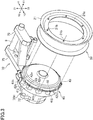
Fig. 3] Fig. 3 is a perspective view illustrating the rear wheel, the electric motor, and the rear arm, in which the rear wheel and a housing of the electric motor are separated. - [
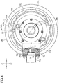
Fig. 4] Fig. 4 is a side view illustrating the rear wheel, the electric motor, and the rear arm. - [
Fig. 5A] Fig. 5A is a cross-sectional view taken along the line VA-VA illustrated inFig. 4 . - [
Fig. 5B] Fig. 5B is an enlarged view ofFig. 5A . - [
Fig. 6] Fig.6 is a perspective view illustrating the inside of a component housing configured by the rear arm. - [
Fig. 7] Fig. 7 is a perspective view illustrating an arm rear member that constitutes the component housing. InFig. 7 , the side facing a motor housing is illustrated. - [
Fig. 8] Fig. 8 is a perspective view illustrating the arm rear member to which a brake shoe is attached. - [
Fig. 9] Fig. 9 is a cross-sectional view illustrating a modification example of a cable passage formed on the axle. - [
Fig. 10] Fig. 10 is a cross-sectional view illustrating a modification example of a straddled electric vehicle. - Hereinafter, an example of the straddled electric vehicle proposed in the present disclosure will be described. In the present specification, an electric two-wheeled vehicle is described as an example of a straddled electric vehicle. The straddled electric vehicle may be an electric three-wheeled vehicle, an electric four-wheeled vehicle, or the like.
- In
Figs. 1 to 8 , the directions indicated by Y1 and Y2 are referred to as frontward direction and rearward direction, respectively, and the directions indicated by Z1 and Z2 are referred to as upward direction and downward direction, respectively. The directions indicated by X1 and X2 are referred to as the rightward direction and leftward direction, respectively. - An electric two-wheeled vehicle 1 is an example of an embodiment of the electric vehicle proposed in the present disclosure. In the electric two-wheeled vehicle 1, a
rear arm 70 is placed on the left side of arear wheel 20. Depending on the positional relationship between therear wheel 20 and therear arm 70, the positional relationships in the left-right direction of a plurality of components, a plurality of members, and a plurality of portions are illustrated. These positional relationships may be opposite in the left-right direction. That is, in the following description, "right" may be read as "left" and "left" may be read as "right". - As illustrated in
Fig. 1 , the electric two-wheeled vehicle 1 includes afront wheel 2, afront fork 3 supporting thefront wheel 2, and ahandlebar 4 connected to an upper portion of thefront fork 3.Grips 4a are provided on the right and left ends of thehandlebar 4. For example, one grip (right grip 4a) is an accelerator grip, and a rider can adjust the output of an electric motor 30 (seeFig. 5A ) described later through theright grip 4a. Aseat 5 is placed behind thehandlebar 4. The electric two-wheeled vehicle 1 is a so-called scooter type vehicle, and between theseat 5 and thefront fork 3, a space for the rider to put his or her feet and afoot board 6 for putting his or her feet are provided. The electric two-wheeled vehicle 1 may not be a scooter type vehicle. That is, the electric two-wheeled vehicle 1 may be a vehicle that allows the rider to ride while sandwiching the vehicle body with his or her feet. - As illustrated in
Fig. 1 , the electric two-wheeled vehicle 1 includes therear wheel 20 and therear arm 70 that supports therear wheel 20 so that therear wheel 20 can move up and down, at a rear portion thereof. Atire 13 is attached to therear wheel 20. A pivot shaft 9 (seeFig. 2 ) is provided at the front end of therear arm 70. Therear arm 70 is connected to the vehicle body frame via thepivot shaft 9 and can move up and down about thepivot shaft 9. Therear arm 70 supports an axle 31 (seeFig. 5A ) of therear wheel 20. The electric two-wheeled vehicle 1 includes an electric motor 30 (seeFig. 5A ) that drives therear wheel 20. The electric two-wheeled vehicle 1 is an in-wheel motor type vehicle, and thus theelectric motor 30 is placed on theaxle 31 and is located inside therear wheel 20. The electric two-wheeled vehicle 1 includes a battery (not illustrated) and an inverter. The direct current supplied from the battery is converted into alternating current by the inverter to be supplied to theelectric motor 30. - The
rear arm 70 is placed only to one of the right and the left of therear wheel 20 and supports only one of the right end and the left end of theaxle 31. That is, theaxle 31 is supported like a cantilever. In the exampled electric two-wheeled vehicle 1, therear arm 70 is placed only on the left of therear wheel 20 and supports only aleft end 31r of the axle 31 (seeFig. 5A ). As illustrated inFig. 2 , therear arm 70 includes aleft arm 71 extending rearward from the left portion of thepivot shaft 9 and aright arm 79 extending rearward from the right portion of thepivot shaft 9. A rear portion of the left arm 71 (specifically, an armrear member 72 described later) is located to the left of therear wheel 20 and supports aleft end 31r of theaxle 31 of the rear wheel 20 (seeFig. 5A ). The rear portion of theleft arm 71 includes acylindrical portion 72a, and the left portion of theaxle 31 is inserted inside theportion 72a (seeFig. 5A , hereinafter, theportion 72a is referred to as a "axle holding portion"). - The
right arm 79 is shorter than theleft arm 71, and the rear end of theright arm 79 does not reach theaxle 31. In the exampled electric two-wheeled vehicle 1, the rear end of theright arm 79 is located in front of therear wheel 20. Therefore, aright end 31a of theaxle 31 is not supported by theright arm 79. That is, theright arm 79 is not connected to theright end 31a of theaxle 31. Theaxle 31 may be a single member that is continuous from theright end 31a to theleft end 31r. - With the structure in which only one end of the
axle 31 is supported by therear arm 70 as described above, for example, at the time of maintenance work or repair work, an operator can easily access therear wheel 20 and therear tire 13, and thus workability of the works can be improved. Further, as will be described later in detail, the number of seal members required for amotor housing 40 can be reduced. - In the present specification, the sentence " the
left end 31r of theaxle 31 is supported" means that theaxle holding portion 72a of therear arm 70, which supports theaxle 31, is located further leftward than theelectric motor 30 described later. Therefore, theleft end 31r of theaxle 31 may be located on theaxle holding portion 72a or may protrude leftward from theaxle holding portion 72a. Further, the sentence "theright end 31a of theaxle 31 is not supported" means that therear arm 70 is not connected to a portion of theaxle 31 located further rightward than theelectric motor 30. - As illustrated in
Fig. 2 , therear arm 70 includes a connectingbar 78 located in front of therear wheel 20. The connectingbar 78 is stretched between theright arm 79 and theleft arm 71. The rear arm is not limited to the example of the electric two-wheeled vehicle 1. For example, theright arm 79 may include a portion that overlaps with therear wheel 20 in a side view of the vehicle body, although theright arm 79 is not connected to theaxle 31. In another example, therear arm 70 may support theright end 31a of theaxle 31 and may not support theleft end 31r of theaxle 31, contrary to the example ofFig. 5A . In still another example, therear arm 70 may not include theright arm 79 or the connectingbar 78. - As described above, the
electric motor 30 is placed on theaxle 31. As illustrated inFig. 5A , theelectric motor 30 includes astator 33 and arotor 34 rotatable about theaxle 31. Therotor 34 is located radially outward of thestator 33, and therotor 34 and thestator 33 face each other in the radial direction. As illustrated inFig. 5B , thestator 33 includes a plurality ofiron cores 33a arranged in the circumferential direction of theaxle 31 and acoil 33b wound around eachiron core 33a. Therotor 34 includes a plurality of permanent magnets 34a arranged in the circumferential direction of theaxle 31. - As illustrated in
Fig. 5A , theelectric motor 30 includes astator frame 32 that supports thestator 33. Thestator frame 32 includes a fixedportion 32a fixed to theaxle 31. Thestator 33 is supported by thestator frame 32, whereby the rotational position of thestator 33 is fixed. Theaxle 31 cannot rotate relative to the rear arm 70 (more specifically, the armrear member 72 that constitutes the left arm 71). As illustrated inFig. 5A , therear arm 70 includes a cylindricalaxle holding portion 72a. Theaxle 31 is inserted into theaxle holding portion 72a and cannot rotate relative to theaxle holding portion 72a. In the exampled electric two-wheeled vehicle 1, a key groove extending in the axial direction is formed on the outer peripheral surface of theaxle 31 and the inner peripheral surface of theaxle holding portion 72a, and an engagingmember 38 is placed in the key groove. The engagingmember 38 engages with the outer peripheral surface of theaxle 31 and the inner peripheral surface of theaxle holding portion 72a to restrict the relative rotation thereof. The structure for restricting the rotation of theaxle 31 is not limited to the example illustrated inFig. 5A . - As illustrated in
Fig. 5A , the electric two-wheeled vehicle 1 includes themotor housing 40 that accommodates therotor 34 and thestator 33. Themotor housing 40 is rotatably supported bybearings axle 31. The rotor 34 (permanent magnet 34a) is affixed inside themotor housing 40 and is rotatably supported via themotor housing 40 and thebearings rear wheel 20 is fixed to the outside of themotor housing 40 by a fixing tool such as a bolt or a screw. Therefore, there is no speed reduction mechanism in the power transmission path between therotor 34 and therear wheel 20, and therotor 34 rotates integrally with therear wheel 20. That is, the rotation speed of therotor 34 and the rotation speed of therear wheel 20 are the same. In other words, the electric two-wheeled vehicle 1 is a direct drive type vehicle. - As illustrated in
Fig. 5A , themotor housing 40 includes aleft housing member 41 and aright housing member 42 that are combined with each other in the left-right direction. Theleft housing member 41 is located to the left of theelectric motor 30 and covers the left side of theelectric motor 30. Theright housing member 42 is located to the right of theelectric motor 30 and covers the right side of theelectric motor 30. Theleft housing member 41 has a box shape that is open toward the right side and is circular in a side view. Theright housing member 42 has a box shape that is open toward the left side and is circular in a side view. - As illustrated in
Fig. 5A , theleft end 31r of theaxle 31 is located outside themotor housing 40 and is supported by the rear arm 70 (more specifically, the cylindricalaxle holding portion 72a). Therefore, theaxle 31 penetrates theleft housing member 41. That is, an opening is formed at the center of theleft housing member 41, and theaxle 31 passes through the inside of this opening. A seal member 44 (seeFig. 5B ) is placed between the inner peripheral surface of the opening of theleft housing member 41 and the outer peripheral surface of theaxle 31. Theseal member 44 is, for example, an oil seal. In the exampled electric two-wheeled vehicle 1, anannular member 31f is fitted on the outside of theaxle 31. Theseal member 44 is placed between theannular member 31f and the inner peripheral surface of the opening of theleft housing member 41 and seals therebetween. Theannular member 31f may not be provided on theaxle 31. Thebearing 61 is placed between the inner peripheral surface of the opening of theleft housing member 41 and theaxle 31. Theseal member 44 is located outward in the left-right direction (located leftward) of theleft bearing 61. - As described above, the
right end 31a of theaxle 31 is not supported by therear arm 70. Therefore, as illustrated inFig. 5A , theright end 31a of theaxle 31 does not penetrate theright housing member 42. That is, theright end 31a of theaxle 31 is located inside themotor housing 40, and theright housing member 42 covers the right side of theright end 31a. Therefore, unlike theleft housing member 41, theright housing member 42 does not require a seal member. The number of seal members required between themotor housing 40 and the outer peripheral surface of theaxle 31 can be reduced. As a result, frictional resistance against rotation of the rotor 34 (rotation of the motor housing 40) is reduced, and thus theelectric motor 30 can be efficiently driven. Thebearing 62 is fitted on theright end 31a of theaxle 31, and theright housing member 42 is rotatably supported by theaxle 31 via thebearing 62. A recessedportion 42b is formed at the center of theright housing member 42, and thebearing 62 is placed inside this recessed portion. - Each of the
left housing member 41 and theright housing member 42 is a member integrally formed of metal. That is, theleft housing member 41 is not configured by a plurality of members fixed to each other by a fixing tool such as a screw or a bolt. Similarly, theright housing member 42 is not configured by a plurality of members fixed to each other by a fixing tool such as a screw or a bolt. Therefore, the outer wall of themotor housing 40 is configured by only two members (housing members 41 and 42). - As illustrated in
Fig. 5B , theleft housing member 41 includes aflange portion 41a at the right edge portion thereof, which protrudes from the outer peripheral surface in the radial direction. Similarly, theright housing member 42 includes a flange portion 42a at the left edge thereof, which protrudes from the outer peripheral surface in the radial direction. Theflange portions 41a, 42a are fixed to each other by a plurality of fixing tools 49 (seeFig. 3 ) such as bolts and screws. A ring-shapedseal member 43 is placed between theflange portion 41a of theleft housing member 41 and the flange portion 42a of theright housing member 42. Since theflange portions 41a and 42a protrude in the radial direction from the outer peripheral surfaces of thehousing members seal member 43 can be easily placed. Unlike the electric two-wheeled vehicle 1, the right edge portion of theleft housing member 41 and the left edge portion of theright housing member 42 may not be formed in a flange shape. - The
rotor 34 is fixed to the inside of one of the twohousing members rotor 34 is fixed inside theleft housing member 41. The structure of themotor housing 40 can reduce the number of sealing members required. For example, in a structure of a related art in which the rotor is fixed to the rim portion of the rear wheel and each of the right and left housing members is fixed to the rim portion, two sealing members (a seal member between the rim portion and the right housing member, and a seal member between the rim portion and the left housing member) are required. On the other hand, in themotor housing 40, therotor 34 is fixed on the inside of one of the housing members, and the twohousing members - By the structure described above, the accommodation chamber inside the motor housing 40 (the accommodation chamber in which the
rotor 34 and thestator 33 are placed) is partitioned from the outside. That is, theseal members motor housing 40 from the outside are placed at the edges of the members that define the accommodation chamber. Theseal members housing members seal members seal members seal members housing members - As illustrated in
Fig. 5A , the width of theleft housing member 41 in the left-right direction is larger than the width of theright housing member 42 in the left-right direction. Therotor 34 is fixed on the inside of theleft housing member 41 having a larger width. Therefore, the strength in the attachment of therotor 34 is easily ensured. Since the width of theleft housing member 41 is larger than the width of theright housing member 42, the positions of the flange portions (edge portions) 41a and 42a of thehousing members motor housing 40 in the left-right direction (a center C1 of therear wheel 20 in the left-right direction). Therefore, interference between the components formed on therim portion 21 of therear wheel 20 and themotor housing 40 is easily prevented. In the exampled electric two-wheeled vehicle 1, anair valve 22 is attached to therim portion 21. Interference between theair valve 22 and theedge portions 41a and 42a of thehousing members - Unlike the electric two-wheeled vehicle 1, the width of the
left housing member 41 may be the same as the width of theright housing member 42, or the width of theright housing member 42 may be larger than the width of theleft housing member 41. Therotor 34 may be attached to a housing member having a small width. - As illustrated in
Fig. 5B , themotor housing 40 includes arotor frame 45 fixed on the inside of theleft housing member 41. Therotor frame 45 is welded to the inside of theleft housing member 41, for example. Therotor frame 45 has an annular shape surrounding theaxle 31, and the plurality of permanent magnets 34a forming therotor 34 are fixed on the inner peripheral surface of therotor frame 45. Unlike the electric two-wheeled vehicle 1, themotor housing 40 may not include therotor frame 45. That is, the permanent magnet 34a may be directly fixed to the inside of theleft housing member 41. - As described above, the
stator 33 includes thecoil 33b. As illustrated inFig. 5B , anelectric cable 35 including a plurality of electric wires connected to thecoil 33b is placed in themotor housing 40. The electric wire is connected to thecoil 33b via abus bar 33c attached to thestator 33. Theelectric motor 30 includes a sensor (not illustrated) for detecting the rotational position of therotor 34, asensor substrate 36 connected to the sensor, and aholder 33f that holds thesensor substrate 36. Theelectric cable 35 may also include electric wires extending from thissensor substrate 36. The structure of connecting theelectric cable 35 and thecoil 33b and the structure of supporting thesensor substrate 36 are not limited to the examples illustrated in the drawings. For example, the electric wire of thecable 35 may be directly connected to thecoil 33b without passing through thebus bar 33c. Theholder 33f may not be used to support thesensor substrate 36, but may be attached to, for example, thestator frame 32 or another member. - As illustrated in
Fig. 5B , a cable passage (through-hole) 31b extending in the left-right direction (axial direction) is formed in theaxle 31. Oneend 31c of thecable passage 31b is opened in themotor housing 40. Theother end 31d (seeFig. 5A ) of thecable passage 31b is opened outside the motor housing 40 (hereinafter, theend 31c is referred to as a "motor-side opening end", and theend 31d is referred to as a "battery-side opening end"). As will be described later in detail, acomponent housing 70H is provided on the left of themotor housing 40, and the battery-side opening end 31d is opened in thecomponent housing 70H. Theelectric cable 35 passes through thecable passage 31b and pulled out from the inside of themotor housing 40 to the outside. - As illustrated in
Fig. 5B , the motor-side opening end 31c is located on the outer peripheral surface of theaxle 31. Thecable passage 31b includes a straightaway portion 31e extending linearly in the axial direction and aninclined portion 31g formed obliquely with respect to both the axial direction and the radial direction (direction orthogonal to the axial direction). Theinclined portion 31g extends obliquely from the straightaway portion 31e toward the motor-side opening end 31c. With the structure of thecable passage 31b, since the angle of the bent portion of theelectric cable 35 is smaller than 90 degrees, it is easy to pass theelectric cable 35 through thecable passage 31b. - As described above, the
stator frame 32 includes the fixedportion 32a fixed to the outer peripheral surface of theaxle 31. Theleft end 31r of theaxle 31 is supported by theaxle holding portion 72a of therear arm 70. The motor-side opening end 31c is located on the opposite side of theaxle holding portion 72a across the fixedportion 32a. With such structure, since the motor-side opening end 31c does not interfere with theaxle holding portion 72a, the position of theaxle holding portion 72a can be brought closer to the fixedportion 32a of thestator frame 32. In other words, the position of the right end of theaxle holding portion 72a can be brought closer to the center C1 of therear wheel 20 in the left-right direction. As a result, the supporting strength of theaxle 31 by theaxle holding portion 72a can be increased. In the exampled electric two-wheeled vehicle 1, the bearing 61 that supports themotor housing 40 is placed between the fixedportion 32a and theaxle holding portion 72a. Thebearing 61 and theaxle holding portion 72a are brought close to the fixedportion 32a of thestator frame 32. The position of the motor-side opening end 31c is not limited to the example of the electric two-wheeled vehicle 1. The motor-side opening end 31c may be formed between the bearing 61 and the fixedportion 32a of thestator frame 32. - The
electric motor 30 includes thesensor substrate 36 as described above. As illustrated inFig. 5B , thesensor substrate 36 is located to the right of thestator 33, like the motor-side opening end 31c. Unlike the electric two-wheeled vehicle 1, thesensor substrate 36 may be placed to the left of thestator 33. - The
left arm 71 of therear arm 70 includes theaxle holding portion 72a that holds theaxle 31. Theaxle holding portion 72a has a cylindrical shape, and theaxle 31 is inserted into theaxle holding portion 72a. Theleft arm 71 includes, at the rear portion thereof, thecomponent housing 70H (seeFig. 5A ) located to the left of themotor housing 40. Therefore, thecomponent housing 70H moves up and down together with theaxle 31 with respect to the vehicle body frame. The battery-side opening end 31d of thecable passage 31b is located inside thecomponent housing 70H. With such structure, it is possible to prevent water and soil from entering themotor housing 40 through thecable passage 31. Since thecomponent housing 70H is a part of therear arm 70, an increase in the number of components can be avoided. As illustrated inFig. 6 , in the electric two-wheeled vehicle 1, the battery-side opening end 31d is formed on the end surface of the axle 31 (the surface facing the left). Unlike the electric two-wheeled vehicle 1, the battery-side opening end 31d may be formed on the outer peripheral surface of theaxle 31 like the motor-side opening end 31c. - As illustrated in
Fig. 6 , anelectric component 11 is accommodated in thecomponent housing 70H. Theelectric component 11 is, for example, a component disposed on the electric path between theelectric motor 30 and a battery (not illustrated) that supplies electric power to theelectric motor 30. More specifically, theelectric component 11 is a terminal block that connects, for example, a terminal provided at an end of anelectric wire 35a of theelectric cable 35 and a terminal of anelectric wire 37a extending from the battery. Theelectric component 11 may be a motor driving device including an inverter that converts direct current supplied from the battery into alternating current to supply the alternating current to theelectric motor 30. - By placing the electric component placed in the electric path between the
electric motor 30 and the battery in thecomponent housing 70H, the cable electrically connecting the battery and theelectric motor 30 can be shortened. For example, if the motor driving device is placed at a position different from the rear arm 70 (for example, the lower side of the seat 5), it is necessary to divert the electric cable toward the motor driving device. On the other hand, when the motor driving device is placed in thecomponent housing 70H, the cable can be disposed on a path that is close to the shortest distance from the battery to theelectric motor 30. Theelectric component 11 is not limited to the terminal block or the motor driving device. A plurality of electric components may be placed in thecomponent housing 70H. - As illustrated in
Fig. 5A , in the exampled electric two-wheeled vehicle 1, thecomponent housing 70H includes the armrear member 72 and acover member 73. The armrear member 72 has a box shape that opens to the left. Thecover member 73 is placed to the left of the armrear member 72 and closes the opening of the armrear member 72. The armrear member 72 and thecover member 73 are joined together in the left-right direction. The left edge portion of the armrear member 72 and theright edge portion 73a of thecover member 73 are fixed to each other by a fixing tool such as a screw or a bolt. Theaxle holding portion 72a is formed on the armrear member 72. - A
seal member 72g (seeFig. 6 ) is provided between the armrear member 72 and thecover member 73 to seal therebetween. As a result, it is possible to prevent water from entering the inside of thecomponent housing 70H. That is, the accommodation chamber of thecomponent housing 70H is also partitioned from the outside, like the accommodation chamber of themotor housing 40. The sealingmaterial 72g is applied to the left edge portion of the armrear member 72, for example. The sealingmaterial 72g may be an O-ring or a gasket attached to the left edge portion of the armrear member 72. - As illustrated in
Fig. 5A , the armrear member 72 includes aside wall portion 72b placed along themotor housing 40 and intersecting with theaxle holding portion 72a, and aperipheral wall portion 72c surrounding theaxle 31 in a side view. Abrake device 80 is placed between thecomponent housing 70H (side wall portion 72b) and the motor housing 40 (left housing member 41). The placement of thebrake device 80 will be described later in detail. - As illustrated in
Fig. 7 , theaxle holding portion 72a includes a right protrudingportion 72e protruding rightward from theside wall portion 72b. The armrear member 72 includes a plurality ofribs 72h formed on the outer peripheral surface of theright protruding portion 72e. The plurality ofribs 72h are arranged in the circumferential direction of theaxle 31. Therib 72h is substantially parallel to theaxle 31 and is connected to the outer peripheral surface of theright protruding portion 72e, the right surface of theside wall portion 72b, and theperipheral wall portion 72c. Therib 72h can increase the strength of theaxle holding portion 72a against the force acting from theaxle 31 to theaxle holding portion 72a. In the exampled electric two-wheeled vehicle 1, since therear arm 70 does not support theright end 31a of theaxle 31, the structure for increasing the strength of theright protruding portion 72e of theaxle holding portion 72a is particularly effective. - As illustrated in
Fig. 6 , theaxle holding portion 72a includes a left protrudingportion 72f protruding leftward from theside wall portion 72b. The armrear member 72 includes a plurality ofribs 72i formed on the outer peripheral surface of theleft protruding portion 72f. Like therib 72h, the plurality ofribs 72i are arranged in the circumferential direction of theaxle 31. Therib 72i is substantially parallel to theaxle 31 and is connected to the outer peripheral surface of theleft protruding portion 72f, the left surface of theside wall portion 72b, and theperipheral wall portion 72c. Therib 72i can further increase the strength against the force acting from theaxle 31 to theaxle holding portion 72a. - As illustrated in
Fig. 5A , the length of theleft protruding portion 72f is larger than the length of theright protruding portion 72e. Therefore, theside wall portion 72b is located to the right of a center C2 of theaxle holding portion 72a in the left-right direction. As a result, the position of theside wall portion 72b approaches the center C1 of therear wheel 20 in the left-right direction, and thus the support strength of theaxle 31 by therear arm 70 can be further improved. - As illustrated in
Fig. 2 , theleft arm 71 includes anarm front member 75 extending rearward from thepivot shaft 9. In the exampled electric two-wheeled vehicle 1, thecomponent housing 70H is connected to the rear side of thearm front member 75. Thearm front member 75 includes a plate-shaped attachingportion 75a at the rear end thereof. Thecomponent housing 70H is attached to the attachingportion 75a. In the exampled electric two-wheeled vehicle 1, the armrear member 72 includes afront wall portion 72j (seeFig. 6 ) . Thefront wall portion 72j is connected to the attachingportion 75a by a fixing tool such as a screw or a bolt. Therear arm member 72 and thefront arm member 75 may be made of the same material or different materials. For example, therear arm member 72 may be made of aluminum, and thefront arm member 75 may be made of iron, for example. - The structure of the
left arm 71 is not limited to the example of the electric two-wheeled vehicle 1. For example, the armrear member 72 and thearm front member 75 may be integrally formed. That is, the armrear member 72 and thearm front member 75 may not be connected to each other by a fixing tool, but may be single member formed by casting, for example. - In the exampled electric two-wheeled vehicle 1, the
arm front member 75 is a tubular member. As illustrated inFig. 4 , the accommodation chamber inside thecomponent housing 70H and the inside of thearm front member 75 are connected to each other. In the exampled electric two-wheeled vehicle 1, ahole 72k (seeFigs. 4 and6 ) that penetrates thefront wall portion 72j in the front-rear direction is formed in thefront wall portion 72j of the armrear member 72. The attachingportion 75a of thearm front member 75 is formed in an annular shape and is attached to the front surface of the outer peripheral portion of thefront wall portion 72j by a fixing tool 76 such as a bolt or a screw. A recessedportion 72v is formed inside the outer peripheral portion of thefront wall portion 72j (the portion where the fixing tool 76 is attached). Theelectric wire 37a (seeFig. 6 ) extending from theelectric component 11 passes through thehole 72k and the inside of thearm front member 75 and reaches the battery. - The outer wall of the
component housing 70H includes ventilation holes that connect the inside to the outside. The ventilation holes can prevent the air pressure in thecomponent housing 70H and themotor housing 40 from changing due to temperature changes. In the exampled electric two-wheeled vehicle 1, as illustrated inFig. 4 , aventilation hole 72t is formed in thefront wall portion 72j of thecomponent housing 70H. Theventilation hole 72t connects the inside of thecomponent housing 70H and the inside of the arm front member 75 (tubular member). A ventilation hole may be formed in thearm front member 75 for connecting the inside of thearm front member 75 and the outside (atmosphere). - It is desirable that the
ventilation hole 72t be provided with a waterproof structure. Aseal member 74 made of, for example, a material (fiber) having waterproofness and breathability is attached to theventilation hole 72t. By using such a material, it is possible to appropriately maintain the pressures of thecomponent housing 70H and themotor housing 40 while preventing water from entering thecomponent housing 70H and themotor housing 40 from thearm front member 75. The waterproof structure is not limited to theseal member 74 and may be, for example, a pipe inserted into theventilation hole 72t. The pipe may extend through the inside of thearm front member 75 to the inside of the exterior cover of the vehicle body and further to the lower side of theseat 5. By doing so, it is possible to prevent water from entering thecomponent housing 70H through the pipe. The position of theventilation hole 72t and the waterproof structure are not limited to the example of the electric two-wheeled vehicle 1. - As illustrated in
Fig. 4 , in the electric two-wheeled vehicle 1, thecomponent housing 70H has a width (height) h1 in the vertical direction larger than that of thearm front member 75. As a result, sufficient capacity can be secured in thecomponent housing 70H. As illustrated inFig. 6 , theperipheral wall portion 72c of the armrear member 72 includes anupper wall portion 72n and alower wall portion 72p that are located in front of theaxle 31 and extend forward. As a result, sufficient capacity can be secured in thecomponent housing 70H. In the example illustrated inFig. 6 , theelectric component 11 is placed between theupper wall portion 72n and thelower wall portion 72p. - The placement of the
electric component 11 and the shape of thecomponent housing 70H are not limited to the example of the electric two-wheeled vehicle 1. For example, thecomponent housing 70H may not include theupper wall portion 72n and thelower wall portion 72p. Here, theelectric component 11 may be placed inside acurved portion 72m that is curved to surround theaxle 31. In the example illustrated inFig. 6 , a recessedportion 72q is formed in thecurved portion 72m, and alever 84 for operating thebrake device 80 is placed in the recessedportion 72q. However, such a recessedportion 72q may not be formed in thecurved portion 72m. - The electric two-wheeled vehicle 1 includes a rear suspension 14 (see
Fig. 1 ). As illustrated inFig. 6 , asuspension connecting portion 72r to which the lower end of therear suspension 14 is connected is formed in thecomponent housing 70H. In the electric two-wheeled vehicle 1, thesuspension connecting portion 72r is formed on theperipheral wall portion 72c (more specifically, thecurved portion 72m) of the armrear member 72. Therib 72i described above is also connected to the inner surface of theperipheral wall portion 72c (the inner surface of thecurved portion 72m). Therib 72i can improve the strength of thecomponent housing 70H against the force acting from thesuspension 14. Unlike the electric two-wheeled vehicle 1, thesuspension connecting portion 72r may be formed in a portion different from theperipheral wall portion 72c of the armrear member 72. - As described above, the
cover member 73 is fixed to the armrear member 72. In the exampled electric two-wheeled vehicle 1, thecover member 73 is made of metal. As a result, the strength of thecomponent housing 70H against the force acting from thesuspension 14 can be further improved. The material of thecover member 73 may be aluminum or iron. Unlike the electric two-wheeled vehicle 1, thecover member 73 may be made of resin. - As described above, the
stator frame 32 includes the fixedportion 32a fixed to the axle 31 (seeFig. 5A ). In the exampled electric two-wheeled vehicle 1, the fixedportion 32a has an annular shape, and theaxle 31 is inserted inside thereof. The fixedportion 32a is fixed to theaxle 31 to not rotate relative to theaxle 31. The fixedportion 32a is welded to the outer peripheral surface of theaxle 31, for example. Relative rotation between the fixedportion 32a and theaxle 31 may be restricted not by welding, but by a spline formed on the inner peripheral surface of the fixedportion 32a and the outer peripheral surface of theaxle 31, or by a key that engages with the inner peripheral surface of the fixedportion 32a and the outer peripheral surface of theaxle 31. - As illustrated in
Fig. 5B , thestator frame 32 includes, in the outer peripheral portion thereof, astator attaching portion 32b that has an annular shape surrounding theaxle 31. In the electric two-wheeled vehicle 1, thestator 33 is fixed to the outer peripheral surface of thestator attaching portion 32b. Specifically, a plurality ofiron cores 33a are attached on the outer peripheral surface of thestator attaching portion 32b. Theiron core 33a is welded to the outer peripheral surface of thestator attaching portion 32b, for example. - As illustrated in
Fig. 5B , thestator frame 32 includes a connectingportion 32c that extends in the radial direction from the fixedportion 32a to thestator attaching portion 32b and connects both. The connectingportion 32c has, for example, a disc shape. The fixedportion 32a is formed at the center of the connectingportion 32c, and thestator attaching portion 32b is formed at the outer peripheral edge of the connectingportion 32c. The connectingportion 32c may not be disc-shaped as long as the connectingportion 32c has a shape that connects the fixedportion 32a and thestator attaching portion 32b. - As described above, the
left end 31r of theaxle 31 is supported by therear arm 70, but theright end 31a is not supported by therear arm 70. As illustrated inFig. 5B , the fixedportion 32a of thestator frame 32 is deviated rightward from the center C1 of therear wheel 20 in the left-right direction. That is, the center of the fixedportion 32a in the left-right direction is located to the right of the center C1 of therear wheel 20. In the exampled electric two-wheeled vehicle 1, the entire fixedportion 32a is located to the right of the center C1 and does not intersect with a plane passing through the center C1 (a plane orthogonal to the axle 31). With such structure, the right end of theaxle holding portion 72a of therear arm 70 supporting theaxle 31 can be brought close to the center C1 of therear wheel 20. As a result, the support strength of theaxle 31 by theaxle holding portion 72a can be improved. As described above, theaxle holding portion 72a includes theright protruding portion 72e protruding rightward from theside wall portion 72b. The right end (the end of theright protruding portion 72e) of theaxle holding portion 72a is located substantially at the center of theaxle 31 in the axial direction. - The positional relationship between the fixed
portion 32a and the center C1 of therear wheel 20 is not limited to the example of the electric two-wheeled vehicle 1. For example, the fixedportion 32a may intersect with a plane passing through the center C1 (a plane orthogonal to the axle 31). Contrary to the electric two-wheeled vehicle 1, therear arm 70 may support theright end 31a of theaxle 31 and may not support theleft end 31r. In that structure, the fixedportion 32a of thestator frame 32 may be deviated leftward from the center C1 of therear wheel 20. - In the exampled electric two-wheeled vehicle 1, the right end of the fixed
portion 32a is located further leftward than the right end of thestator 33, and thus the entire fixedportion 32a is located inward of thestator 33 in the radial direction. Unlike the exampled the electric two-wheeled vehicle 1, the right end of the fixedportion 32a may be located further rightward than the right end of thestator 33. - As illustrated in
Fig. 5B , thestator 33 is located further leftward than the fixedportion 32a of thestator frame 32. As a result, the positional displacement between thestator 33 and therear wheel 20 in the left-right direction can be reduced. As a result, it is possible to prevent theelectric motor 30 and themotor housing 40 from greatly protruding to the right of therear wheel 20. In the exampled electric two-wheeled vehicle 1, the position of thestator 33 in the left-right direction matches therear wheel 20. That is, the center of thestator 33 in the left-right direction is located at the center C1 of therear wheel 20. Unlike the exampled electric two-wheeled vehicle 1, the center of thestator 33 in the left-right direction may be located to the right of the center C1 of therear wheel 20, or may be located to the left of the center C1 of therear wheel 20. - As illustrated in
Fig. 5B , the connectingportion 32c of thestator frame 32 includes aninclined portion 32e that is inclined with respect to the radial direction of theaxle 31. Due to the shape of thestator frame 32, the position of thestator 33 can be located further leftward than the fixedportion 32a. Thestator frame 32 does not need to include theinclined portion 32e. For example, the connectingportion 32c of thestator frame 32 may be parallel to the radial direction of theaxle 31. In that structure, in order to position thestator 33 to be located further leftward than the fixedportion 32a, the end of the connectingportion 32c (the end between the connectingportion 32c and thestator attaching portion 32b) may be shifted to the right from the center of thestator 33 in the left-right direction. As still another example, the connectingportion 32c may include a step instead of theinclined portion 32e. - As described above, the
rotor 34 is rotatably supported by thebearings Fig. 5B , thebearing 61 is located to the left of the fixedportion 32a of thestator frame 32, and thebearing 62 is located to the right of the fixedportion 32a of the stator frame 32 (hereinafter, thebearing 61 is referred to as a "left bearing" and thebearing 62 is referred to as a " right bearing"). Theleft bearing 61 is located inwardly of thestator 33 in the radial direction of theaxle 31. In other words, when viewed in a direction orthogonal to theaxle 31, thestator 33 overlaps with theleft bearing 61. Theleft bearing 61 is located to the right of a plane P3 passing through the left end of thestator 33. In the exampled electric two-wheeled vehicle 1, the entire left bearing 61 is located to the right of the plane P3 passing through the left end of thestator 33. - The
left bearing 61 is placed in a space obtained by shifting the fixedportion 32a to the right of the center C1 of therear wheel 20. As a result, the right end of theaxle holding portion 72a that supports theaxle 31 can be brought closer to the center C1 of therear wheel 20, and thus the support strength of theaxle 31 by theaxle holding portion 72a can be improved. Since theleft bearing 61 is located to the right of the plane P3 passing through the left end of thestator 33, the width of themotor housing 40 and thecomponent housing 70H in the left-right direction can be reduced. The placement of theleft bearing 61 is not limited to the example of the electric two-wheeled vehicle 1. For example, only a part of theleft bearing 61 may be located on the right side of the plane P3 passing through the left end of thestator 33. - As illustrated in
Fig. 5B , theleft bearing 61 is located to the left of the center C1 of therear wheel 20, and theright bearing 62 is located to the right of the center C1. With such placement of thebearings electric motor 30 and therear wheel 20 as compared with, for example, a structure in which both of the twobearings rear wheel 20, and the entire right bearing 62 is located to the right of the center C1. - As illustrated in
Fig. 5B , the distance from the left bearing 61 to the center C1 of therear wheel 20 is smaller than the distance from the right bearing 62 to the center C1 of therear wheel 20. Therefore, a larger load acts on the left bearing 61 than on theright bearing 62. Therefore, the width of theleft bearing 61 in the left-right direction is larger than the width of theright bearing 62 in the left-right direction. In other words, the rated load of theleft bearing 61 is larger than the rated load of theright bearing 62. The "rated load" means "a load with a constant direction and size so that a rated life of 1 million rotations can be obtained." - As illustrated in
Fig. 5B , theleft housing member 41 includes a recessedportion 41c in aside wall portion 41f facing thecomponent housing 70H (hereinafter, this recessedportion 41c is referred to as an "accommodating recessed portion "). The accommodating recessedportion 41c is recessed toward the inside of themotor housing 40. That is, the accommodating recessedportion 41c is recessed toward the fixedportion 32a of thestator frame 32. The accommodating recessedportion 41c includes acylindrical wall portion 41d surrounding theaxle 31 in a side view, and awall portion 41e extending from thewall portion 41d toward the axle 31 (thewall portion 41d is referred to as a "cylindrical wall portion", and thewall portion 41e is referred to as an " inner wall portion "). The accommodating recessedportion 41c is formed at a position where theaxle 31 is placed. That is, the opening through which theaxle 31 passes is formed in theinner wall portion 41e. Theseal member 44 and theleft bearing 61 are provided in theinner wall portion 41e. Theinner wall portion 41e is located inside thestator 33 in the radial direction of theaxle 31. - As described above, the
brake device 80 that applies the braking force to therear wheel 20 is placed between themotor housing 40 and thecomponent housing 70H. As illustrated inFig. 5A , thebrake device 80 is placed inside the accommodating recessedportion 41c. That is, at least a part of thebrake device 80 is placed inwardly of thecylindrical wall portion 41d of the accommodating recessedportion 41c in the radial direction. The placement of thebrake device 80 can reduce the size of the mechanism (the mechanism including thebrake device 80 and the electric motor 30) provided on theaxle 31 in the left-right direction. - In the electric two-wheeled vehicle 1, the
brake device 80 is a drum brake device. Thebrake device 80 includes a pair ofbrake shoes Fig. 8 ) and a cam 82 (seeFigs. 5A and8 ) that pushes and spreads thebrake shoes Fig. 5A , thecam 82 includes ashaft portion 82a. Theshaft portion 82a is held by theside wall portion 72b of the armrear member 72. Alever 84 is attached to the end of theshaft portion 82a. Thelever 84 is connected to an operation member (for example, a lever provided on the handlebar 4) operable by the rider via a wire (not illustrated) . Thebrake shoes Fig. 8 ) held by theside wall portion 72b of the armrear member 72. - As illustrated in
Figs. 5A and5B , thebrake shoes cam 82 are placed inside the accommodating recessedportion 41c. By the action of thecam 82, thebrake shoes cylindrical wall portion 41d of the accommodating recessedportion 41c. In the exampled electric two-wheeled vehicle 1, acylindrical friction material 48 against which thebrake shoes cylindrical wall portion 41d. Unlike the electric two-wheeled vehicle 1, thefriction material 48 may not be provided on the inner peripheral surface of thecylindrical wall portion 41d, and thebrake shoes cylindrical wall portion 41d. - Thus, the
brake device 80 is placed inside the accommodating recessedportion 41c, and as a result, a part of thebrake device 80 is located inwardly of thestator 33 in the radial direction of theaxle 31. That is, when viewed in a direction orthogonal to theaxle 31, a part of thebrake device 80 overlaps with thestator 33. More specifically, a part of thebrake shoes coil 33b. Theleft bearing 61 is located further rightward than thebrake device 80. With such placement, the size of the mechanism (the mechanism including thebrake device 80 and the electric motor 30) provided on theaxle 31 in the left-right direction can be reduced. - As described above, the
right protruding portion 72e of theaxle holding portion 72a protrudes from theside wall portion 72b of the armrear member 72 toward themotor housing 40. As illustrated inFig. 5B , in the electric two-wheeled vehicle 1, theright protruding portion 72e is located in the accommodating recessedportion 41c. Specifically, theright protruding portion 72e is located inwardly of thecylindrical wall portion 41d of the accommodating recessedportion 41c in the left-right direction. Therefore, a plane (the plane perpendicular to the axle 31) P4 passing through the end of theright protruding portion 72e intersects with thecylindrical wall portion 41d of the accommodating recessedportion 41c. - At least a part of the
right protruding portion 72e is located inwardly of thebrake device 80 in the radial direction of theaxle 31. Specifically, when viewed in a direction orthogonal to theaxle 31, at least a part of theright protruding portion 72e overlaps with thebrake shoes axle holding portion 72a is close to the center C1 of therear wheel 20, the support strength of the axle 1 by theaxle holding portion 72a can be increased. As illustrated inFig. 5B , theright protruding portion 72e abuts theannular member 31f that supports theseal member 44. - The structure of the
left housing member 41 and the placement of thebrake device 80 are not limited to the example of the electric two-wheeled vehicle 1. Unlike the electric two-wheeled vehicle 1, for example, the accommodating recessedportion 41c may not be formed in theleft housing member 41. In that structure, thebrake device 80 may be located to the left of theside wall portion 41f of theleft housing member 41. - The
left housing member 41 of themotor housing 40 and theside wall portion 72b of the armrear member 72 have a labyrinth structure that reduces water entering the accommodating recessedportion 41c. Specifically, as illustrated inFig. 5B , theleft housing member 41 includes aconvex portion 41g that further protrudes from thecylindrical wall portion 41d of the accommodating recessedportion 41c toward the armrear member 72. Theconvex portion 41g has a ring shape surrounding theaxle 31 in a side view. On the other hand, a recessedportion 72s is formed in theside wall 72b of the armrear member 72. Theconvex portion 41g is located inside the recessedportion 72s. Since the gap between the inner surface of the recessedportion 72s and theconvex portion 41g is bent, it is possible to reduce the amount of water entering the accommodating recessedportion 41c from the outside. That is, theconvex portion 41g and the recessedportion 72s form a labyrinth structure. - As illustrated in
Fig. 5B , aseal member 39a is placed between the outer peripheral surface of theaxle 31 and the inner peripheral surface of theannular member 31f. Aseal member 39b is also placed between the inner peripheral surface of theright protruding portion 72e of theaxle holding portion 72a and the outer peripheral surface of theaxle 31. With theseal members portion 41c from entering themotor housing 40 and thecomponent housing 70H. - As described above, the
motor housing 40 includes theleft housing member 41 and theright housing member 42 that are joined together in the left-right direction. Themotor housing 40 is provided with a first fixing tool (bolts or screws) for fixing the left andright housing members rear wheel 20 to themotor housing 40. Therefore, therear wheel 20 can be removed from themotor housing 40 while maintaining the state where theleft housing member 41 and theright housing member 42 are joined together. As a result, workability of works such as tire maintenance work can be improved. As described above, themotor housing 40 is provided with theseal members motor housing 40 is sealed in order to prevent water from entering the inside thereof. Therear wheel 20 can be removed from themotor housing 40 while maintaining the state where theleft housing member 41 and theright housing member 42 are sealed. - As illustrated in
Fig. 3 , theleft housing member 41 includes a plurality of attachingportions 41j arranged along the right edge thereof at intervals in the circumferential direction of theaxle 31. Theright housing member 42 includes a plurality of attachingportions 42c arranged along the left edge thereof at intervals in the circumferential direction of the axle 31 (hereinafter, the attachingportions housing attaching portions flange portions 41a and 42a formed on the edges of thehousing members housing attaching portions - The
housing attaching portion 41j of theleft housing member 41 is attached to thehousing attaching portion 42c of theright housing member 42 by the fixing tools 49 (seeFig. 3 , for example, screws) inserted in the left-right direction. In the electric two-wheeled vehicle 1, a screw hole is formed in thehousing attaching portion 41j of theleft housing member 41, and a through-hole is formed in thehousing attaching portion 42c of theright housing member 42. Thefixing tools 49 are inserted into the holes of thehousing attaching portions left housing member 41 and theright housing member 42 to each other. The inserting direction of thefixing tools 49 is not limited to the example of the electric two-wheeled vehicle 1. That is, thehousing attaching portions fixing tools 49 are inserted from the left side thereof. - As illustrated in
Fig. 3 , themotor housing 40 includes a plurality of attachingportions 41k to which therear wheel 20 is attached (hereinafter, the attachingportions 41k are referred to as "wheel attaching portions"). The plurality ofwheel attaching portions 41k are arranged at intervals in the circumferential direction of theaxle 31. In the exampled electric two-wheeled vehicle 1, like thehousing attaching portions wheel attaching portion 41k protrudes more in the radial direction than theflange portions 41a and 42a. Unlike the electric two-wheeled vehicle 1, thewheel attaching portion 41k may not protrude in the radial direction. In the electric two-wheeled vehicle 1, thewheel attaching portion 41k is formed in theleft housing member 41. The plurality ofwheel attaching portions 41k and the plurality ofhousing attaching portions 41j are alternately arranged in the circumferential direction of theaxle 31. - The
rear wheel 20 includes an attachinghole 21b at a position corresponding to thewheel attaching portion 41k, and a fixing tool 47 (seeFig. 5A ) is inserted into the attachinghole 21b. As a result, therear wheel 20 is attached to themotor housing 40. Therefore, by removing the fixingtool 47 from thewheel attaching portion 41k, therear wheel 20 can be removed from themotor housing 40 while maintaining the state where theleft housing member 41 and theright housing member 42 are joined together. - As described above, the
rear arm 70 does not include a portion located at the right side of therear wheel 20. In the electric two-wheeled vehicle 1, the fixingtool 47 that attaches therear wheel 20 to themotor housing 40 is inserted into the screw hole of thewheel attaching portion 41k from the right side of the attachinghole 21b of therear wheel 20, like the fixingtool 49. Therefore, the work of removing the fixingtool 47 can be easily performed. In the exampled electric two-wheeled vehicle 1, theright housing member 42 includes anattachment portion 42e formed at a position corresponding to thewheel attaching portion 41k of theleft housing member 41, and a hole is formed in theattachment portion 42e. The fixingtool 47 is also inserted into the hole of theattachment portion 42e. Theright housing member 42 may not include such anattachment portion 42e. - As illustrated in
Fig. 5A , therear wheel 20 includes an attachedportion 21a that protrudes inward in the radial direction from therim portion 21. The plurality of attachingholes 21b described above are formed in the attachedportion 21a. In the electric two-wheeled vehicle 1, the attachedportion 21a is annular in a side view. Themotor housing 40 is fitted inside the attachedportion 21a. Therear wheel 20 is fitted on the right side of themotor housing 40. The attachedportion 21a is located to the right of the flange portion 42a of theright housing member 42 and abuts the flange portion 42a. Therefore, therear wheel 20 can be removed from themotor housing 40 to the right side. - As described above, the attached
portion 21a of therear wheel 20 is annular. When therear wheel 20 is attached to themotor housing 40, the attachedportion 21a is located to the right of thehousing attaching portions rear wheel 20 and themotor housing 40 are viewed from the right side, the fixing tool 49 (seeFig. 3 ) inserted in thehousing attaching portions portion 21a of therear wheel 20, and are not exposed to the right. Therefore, when the operator removes therear wheel 20 from themotor housing 40, it is possible to prevent the fixing tools 49 (seeFig. 3 ) inserted into thehousing attaching portions - The structure for attaching the
rear wheel 20 to themotor housing 40 is not limited to the example of the electric two-wheeled vehicle 1. For example, instead of theleft housing member 41, a wheel attaching portion including a screw hole may be formed in theright housing member 42. In another example, the attachedportion 21a of therear wheel 20 may not be annular. For example, therear wheel 20 may include a plurality of attachedportions 21a arranged at intervals in the circumferential direction of theaxle 31, and the attachingholes 21b may be formed in each of the attachedportions 21a. As still another example, thewheel attaching portion 41k may not be formed along the edges of thehousing members - As illustrated in
Fig. 5B , therear wheel 20 includes theair valve 22 for introducing air into therear tire 13. Theair valve 22 protrudes from therim portion 21 inwardly in the radial direction. As described above, theseal member 43 is provided between theflange portions 41a and 42a of the left andright housing members portion 21c between theair valve 22 and therim portion 21 is located to the left of theseal member 43. In the electric two-wheeled vehicle 1, the connectingportion 21c of theair valve 22 is located at the center of therim portion 21 in the left-right direction. Theair valve 22 is bent and extends leftward from the connectingportion 21c. With the structure, theair valve 22 and theseal member 43 do not intersect. Therefore, for example, as compared with the case where theseal member 43 and theair valve 22 intersect (that is, where theair valve 22 extends to the right), it is easy to secure sufficient radii of themotor housing 40 and theelectric motor 30, and high output torque can be obtained from theelectric motor 30. - As illustrated in
Fig. 5A , an outer diameter R1 of theflange portions 41a and 42a of the left andright housing members axle 31 to theair valve 22. Therefore, a part of theair valve 22 overlaps with theflange portions 41a and 42a in a side view of therear wheel 20. With such positional relationship, theelectric motor 30 can have a sufficient diameter. - As illustrated in
Fig. 4 , agroove 41h corresponding to the position of theair valve 22 is formed on the outer peripheral surface of the motor housing 40 (the outer peripheral surface of the left housing member 41). As a result, it is easier to secure a sufficient diameter for theelectric motor 30. In the example illustrated inFig. 4 , onegroove 41h is formed on the outer peripheral surface of theleft housing member 41. Unlike the example ofFig. 4 , a plurality ofgrooves 41h may be formed on the outer peripheral surface of theleft housing member 41, and eachgroove 41h may be formed between two adjacenthousing mounting portions 41j andwheel attaching portions 41k. In that structure, theair valve 22 can be placed in anygroove 41h. - As illustrated in
Fig. 5B , an end (cap) 22a of theair valve 22 is located to the left of a left edge 41i (corner of the left housing member 41) of the outer peripheral surface of theleft housing member 41. With the structure, when thetire 13 is inflated with therear wheel 20 attached to themotor housing 40, interference between the tip of the tube extending from an air pump and the outer peripheral surface of theleft housing member 41 is prevented. Since theair valve 22 extends to theleft arm 71 side of therear arm 70 supporting theaxle 31, it is possible to prevent the unnecessary external force from acting on theair valve 22 when theair valve 22 is not used. - The straddled electric vehicle proposed in the present specification is not limited to the electric two-wheeled vehicle 1 described with reference to
Figs. 1 to 8 . -
Fig. 9 is a cross-sectional view illustrating a modification example of the electric two-wheeled vehicle 1. InFig. 9 , the same portions as those described so far are denoted by the same reference numerals, and the description thereof will be omitted. Thecable passage 31b is formed in theaxle 31 as described above. As illustrated inFig. 9 , the battery-side opening end 31d of thecable passage 31b located in thecomponent housing 70H may be formed on the outer peripheral surface of theaxle 31. In the example ofFig. 9 , the left end of theaxle 31, and apart 72u of theleft protruding portion 72f of theaxle holding portion 72a are cut out. Theelectric cable 35 extends from the cutout portion into thecomponent housing 70H. -
Fig. 10 is a cross-sectional view illustrating another modification example of the electric two-wheeled vehicle 1. InFig. 10 , the same portions as those described so far are denoted by the same reference numerals, and the description thereof will be omitted. As illustrated inFig. 10 , the electric two-wheeled vehicle 1 may include abrake device 180. Thebrake device 180 is a disc brake device, and includes adisc 181 that is attached to theleft housing member 41 of themotor housing 40, apad 182 sandwiching thedisc 181, apiston 183, and acaliper 184. Thecaliper 184 is attached to thecomponent housing 70H, for example. -
- (1) As described above, the electric two-wheeled vehicle 1 includes the
rear arm 70 that supports theleft end 31r of theaxle 31 and does not support theright end 31a of theaxle 31, and theelectric motor 30 that includes thestator frame 32 including the affixedportion 32a affixed to theaxle 31, thestator 33 supported by thestator frame 32, and therotor 34 rotatably supported by theaxle 31 and connected to therear wheel 20 to rotate integrally with therear wheel 20, and the fixedportion 32a of thestator frame 32 is shifted rightward from the center C1 of therear wheel 20 in the left-right direction. Accordingly, since one of the two ends of the axle 31 (theright end 31a and theleft end 31r) is not supported by therear arm 70, it is possible to obtain a straddled electric vehicle that is superior to the vehicle of the related art in terms of maintenance workability and manufacturing cost. Since the fixedportion 32a of thestator frame 32 is shifted to the right (the direction with an end not supported by the rear arm 70), the portion of therear arm 70 supporting theaxle 31 can be brought closer to the center C1 of therear wheel 20 in the left-right direction. As a result, it is easy to increase the support strength of theaxle 31. - (2) The
rotor 34 is fixed on the inside of themotor housing 40, and therear wheel 20 is fixed on the outside of themotor housing 40. - (3) The
stator 33 is located further leftward than the fixedportion 32a of thestator frame 32. Accordingly, the positional deviation between thestator 33 and therear wheel 20 in the left-right direction can be reduced. As a result, it is possible to prevent theelectric motor 20 and themotor housing 40 from greatly protruding to the right of therear wheel 20. - (4) The electric two-wheeled vehicle 1 includes the
left bearing 61 which is located to the left of the fixedportion 32a of thestator frame 32 and which rotatably supports therotor 34. At least a part of theleft bearing 61 is located inwardly of thestator 33 in the radial direction of theaxle 31. As a result, the size of the mechanism (including the electric motor 30) provided on theaxle 31 in the left-right direction can be reduced. - (5) The electric two-wheeled vehicle 1 includes the
right bearing 62 which is located to the right of the fixedportion 32a of thestator frame 32 and which rotatably supports therotor 34. Theleft bearing 61 is located to the left of the center C1 of therear wheel 20 in the left-right direction, and theright bearing 62 is located to the right of the center C1 of therear wheel 20 in the left-right direction. Accordingly, it is possible to prevent the load from acting on only one of the two bearings. - (6) The distance from the left bearing 61 to the center C1 of the
rear wheel 20 in the left-right direction is smaller than the distance from the right bearing 62 to the center C1 of therear wheel 20 in the left-right direction. The width of theleft bearing 61 in the left-right direction is larger than the width of theright bearing 62 in the left-right direction. Accordingly, the left bearing 61 can receive a large load. - (7) The
rear arm 70 includes theaxle holding portion 72a that supports theleft end 31r of theaxle 31, and a plurality ofribs axle holding portion 72a. According to the vehicle, the support strength of theaxle 31 can be increased. - (8) The
rear arm 70 includes theaxle holding portion 72a that supports theleft end 31r of theaxle 31, themotor housing 40 includes thewall portion 41f facing the left, thewall portion 41f of themotor housing 40 includes the accommodating recessedportion 41c, and the right end of theaxle holding portion 72a is located inside the accommodating recessedportion 41c of themotor housing 40. Accordingly, since the position of the right end of theaxle holding portion 72 can be brought close to the center C1 of therear wheel 20 in the left-right direction, the support strength of theaxle 31 can be increased. - (9) The
rear arm 70 includes theaxle holding portion 72a supporting theleft end 31r of theaxle 31, and theside wall portion 72b on which theaxle holding portion 72a is formed and through which theaxle 31 passes, and theside wall portion 72b is located to the right of the center of theaxle holding portion 72a in the left-right direction. Accordingly, since the position of theside wall portion 72b can be brought closer to the center C1 of therear wheel 20 in the left-right direction, the support strength of the axle can be increased. - (10) The electric two-wheeled vehicle 1 includes the
brake device 80 placed on the left of theelectric motor 30, therear arm 70 includes theaxle holding portion 72a supporting theleft end 31r of theaxle 31, and a part of theaxle holding portion 72a overlaps with thebrake device 80 when viewed in a direction orthogonal to theaxle 31. Since the position of the right end of theaxle holding portion 72a is close to the center C1 of therear wheel 20 in the left-right direction, the support strength of the axle can be increased. - (11) The electric two-wheeled vehicle 1 includes the
brake device 80 placed on the left of theelectric motor 30, and at least a part of thebrake device 80 is located inwardly of thestator 33 in the radial direction of theaxle 31. The size of the mechanism (the mechanism including theelectric motor 30 and the brake device 80) provided on theaxle 31 in the left-right direction can be reduced. - (12) The electric two-wheeled vehicle 1 includes the
brake device 80 placed on the left of themotor housing 40. Themotor housing 40 includes thewall portion 41f facing the left, thewall portion 41f of themotor housing 40 includes the accommodating recessedportion 41c, and at least a part of thebrake device 80 is located in the accommodating recessedportion 41c of thewall portion 41f of themotor housing 40. The size of the mechanism (the mechanism including theelectric motor 30 and the brake device 80) provided on theaxle 31 in the left-right direction can be reduced. - (13) The electric two-wheeled vehicle 1 includes the
left bearing 61 that is located to the left of the fixedportion 32a of thestator frame 32 and rotatably supports therotor 34, and at least a part of theleft bearing 61 is located closer to the center C1 of therear wheel 20 in the left-right direction than thebrake device 80. - (14) The electric two-wheeled vehicle 1 includes the
electric motor 30 that includes thestator frame 32 including the fixedportion 32a fixed to theaxle 31, thestator 33 attached by thestator frame 32, therotor 34 rotatably supported via the left bearing 61 and connected to therear wheel 20 to rotate integrally with therear wheel 20, theleft bearing 61 is located to the left of the fixedportion 32a, the fixedportion 32a of thestator frame 32 is shifted rightward from the center C1 of therear wheel 20 in the left-right direction, and at least a part of theleft bearing 61 overlaps with thestator 33 when viewed in a direction orthogonal to theaxle 31. The size of the mechanism (including the electric motor 30) for driving therear wheel 20 provided on theaxle 31 in the left-right direction can be reduced. In the vehicle of (14), both ends of theaxle 31 may be supported by therear arm 70. - (15) The electric two-wheeled vehicle 1 includes the
rear wheel 20, theaxle 31, the rear arm that is connected to the body frame and supports the end of theaxle 31, the left bearing 61 located on theaxle 31, themotor housing 40 rotatably supported by theaxle 31 via the left bearing 61, and theelectric motor 30 that includes therotor 34 rotatable around theaxle 31 together with themotor housing 40, thestator frame 32 fixed to theaxle 31, and thestator 33 attached to thestator frame 32 and accommodated in themotor housing 40. Themotor housing 40 includes theside wall portion 41f that is located to the right or the left of theelectric motor 30 and covers theelectric motor 30. At least a part of theleft bearing 61 is located inside thestator 33 in the radial direction of theaxle 31 and is located between the center C1 of a vehicle 201 in the left-right direction and theside wall portion 41f of themotor housing 40. According to the present embodiment, the width of the entire device including theelectric motor 30 and themotor housing 40 in the left-right direction can be reduced. - 1: electric two-wheeled vehicle, 2: front wheel, 3: front fork, 4: handlebar, 4a: grip, 5: seat, 6: foot board, 9: pivot axis, 11: electric component, 13: tire, 14: rear suspension, 20: rear wheel, 21: rim portion, 21a: attached portion, 21b: attaching hole, 21c: connection portion, 22: air valve, 30: electric motor, 31: axle, 31a: right end, 31b: cable passage, 31c: opening end, 31d: opening end,31e: straightaway portion, 31g: inclined portion, 31f: annular member, 31r: left end, 32: stator frame, 32a: fixed portion, 32b: stator attaching portion, 32c: connection portion, 32e: inclined portion, 33: stator, 33a: iron core, 33b: coil, 34: rotor, 34a: permanent magnet, 35: electric cable, 35a: electric wire, 36: sensor substrate, 37a: electric wire, 38: engaging member, 39a: seal member, 39b: seal member, 40: motor housing, 41: left housing member, 41a: flange portion, 41c: accommodating recessed portion, 41d: cylindrical wall portion, 41e: inner wall portion, 41f: side wall portion, 41h: groove, 41i: left edge, 41j: housing attaching portion, 41k: wheel attaching portion, 42: right housing member, 42a: flange portion, 42b: recessed portion, 42c: housing attaching portion, 42e: attached portion, 43: seal member, 44: seal member, 45: rotor frame, 47: fixing tool, 48: friction material, 49: fixing tool, 61: left bearing, 62: right bearing, 70: rear arm, 70H: component housing, 71: left arm, 72: arm rear member, 72i: rib, 72h: rib, 72a: shaft holding portion, 72b: side wall portion, 72c: perimeter wall, 72e: right protruding portion, 72f: left protruding portion, 72j: front wall portion, 72k: hole, 72n: upper wall portion, 72p: lower wall portion, 72q: recessed portion, 72r: suspension connection portion, 72s: recessed portion, 73: cover member, 73a: right edge portion, 75: arm front member, 75a: attaching portion, 78: connecting bar, 79: right arm, 80: brake device, 81a: brake shoe, 81b: brake shoe, 82: cam, 82a: shaft portion, 83: support shaft, 84: lever, 180: brake device, 181: disc, 182: pad, 183: piston, 184: caliper
Claims (15)
- A straddled electric vehicle comprising:a wheel;an axle that includes a first end in a first direction which is one of right and left directions, and a second end in a second direction which is the other direction of the right and left directions;an arm that is connected to a body frame, supports the first end of the axle, and does not support the second end of the axle; andan electric motor that includes a stator frame including a fixed portion fixed to the axle, a stator attached to the stator frame, and a rotor rotatably supported by the axle and connected to the wheel to rotate integrally with the wheel, whereinthe fixed portion of the stator frame is shifted in the second direction from a center of the wheel in a left-right direction.
- The straddled electric vehicle according to claim 1, further comprising:a motor housing that accommodates the rotor and the stator and is rotatably supported by the axle, whereinthe rotor is fixed on the inside of the motor housing, andthe wheel is fixed on the outside of the motor housing.
- The straddled electric vehicle according to claim 1 or 2, wherein
the stator is located further in the first direction than the fixed portion of the stator frame. - The straddled electric vehicle according to any one of claims 1 to 3, further comprising:a first bearing that is located in the first direction of the fixed portion of the stator frame and rotatably supports the rotor, whereinat least a part of the first bearing is located inwardly of the stator in a radial direction of the axle.
- The straddled electric vehicle according to claim 4, further comprising:a second bearing that is located in the second direction of the fixed portion of the stator frame and rotatably supports the rotor, whereinthe first bearing is located in the first direction of a center of the wheel in a left-right direction, andthe second bearing is located in the second direction of the center of the wheel in the left-right direction.
- The straddled electric vehicle according to claim 5, wherein
a distance from the first bearing to the center of the wheel in the left-right direction is smaller than a distance from the second bearing to the center of the wheel in the left-right direction, and
a width of the first bearing in the left-right direction is larger than a width of the second bearing in the left-right direction. - The straddled electric vehicle according to any one of claims 1 to 6, wherein
the arm includes an axle holding portion supporting the first end of the axle, and a plurality of ribs are formed on an outer peripheral surface of the axle holding portion. - The straddled electric vehicle according to claim 2 or 3, wherein
the arm includes an axle holding portion supporting the first end of the axle,
the motor housing includes a wall portion facing the first direction,
the wall portion of the motor housing includes a recessed portion, and
an end of the axle holding portion is located inside the recessed portion of the wall portion of the motor housing. - The straddled electric vehicle according to any one of claims 1 to 8, wherein
the arm includes an axle holding portion supporting the first end of the axle, and a side wall portion in which the axle holding portion is formed and through which the axle passes, and
the side wall portion is located in the second direction of a center of the axle holding portion in a left-right direction. - The straddled electric vehicle according to any one of claims 1 to 9, further comprising:a brake device that is placed in the first direction of the electric motor, whereinthe arm includes an axle holding portion supporting the first end of the axle, anda part of the axle holding portion overlaps with the brake device when viewed in a direction orthogonal to the axle.
- The straddled electric vehicle according to any one of claims 1 to 10, further comprising:a brake device that is placed in the first direction of the electric motor, whereinat least a part of the brake device is located inwardly of the stator in a radial direction of the axle.
- The straddled electric vehicle according to claim 2 or 3, further comprising:a brake device that is placed in the first direction of the motor housing, whereinthe motor housing includes a wall portion facing in the first direction,the wall portion of the motor housing includes a recessed portion, andat least a part of the brake device is located in the recessed portion of the wall portion of the motor housing.
- The straddled electric vehicle according to claim 12, further comprising:a first bearing that is located in the first direction of the fixed portion of the stator frame and rotatably supports the rotor, whereinat least a part of the first bearing is located closer to a center of the wheel in a left-right direction than the brake device.
- A straddled electric vehicle comprising:a wheel;an arm that is connected to a body frame;an axle that is supported by the arm;a bearing that is provided on the axle; andan electric motor that includes a stator frame including an fixed portion fixed to the axle, a stator supported by the stator frame, and a rotor rotatably supported via the bearing and connected to the wheel to rotate integrally with the wheel, whereinthe bearing is located in a first direction which is one of a left direction and a right direction of the fixed portion,the fixed portion of the stator frame is shifted from a center of the wheel in a left-right direction in a second direction which is the other direction of the left direction and the right direction, andat least a part of the bearing overlaps with the stator when viewed in a direction orthogonal to the axle.
- A straddled electric vehicle comprising:a wheel;an axle of the wheel;an arm that is connected to a body frame and supports an end of the axle;a bearing that is disposed on the axle;a motor housing that is rotatably supported by the axle via the bearing; andan electric motor that includes a rotor rotatable together with the motor housing around the axle, a stator frame fixed to the axle, and a stator attached to the stator frame and is accommodated in the motor housing, whereinthe motor housing includes a side wall portion located to a right or a left of the electric motor and covering the electric motor, andat least a part of the bearing is located inside the stator in a radial direction of the axle and is located between a center of the wheel in a left-right direction and the side wall portion of the motor housing.
Applications Claiming Priority (2)
| Application Number | Priority Date | Filing Date | Title |
|---|---|---|---|
| JP2017255155 | 2017-12-29 | ||
| PCT/JP2018/042624 WO2019130903A1 (en) | 2017-12-29 | 2018-11-19 | Saddled electric vehicle |
Publications (2)
| Publication Number | Publication Date |
|---|---|
| EP3733496A1 true EP3733496A1 (en) | 2020-11-04 |
| EP3733496A4 EP3733496A4 (en) | 2021-01-27 |
Family
ID=67063419
Family Applications (1)
| Application Number | Title | Priority Date | Filing Date |
|---|---|---|---|
| EP18897403.4A Pending EP3733496A4 (en) | 2017-12-29 | 2018-11-19 | ELECTRIC SADDLE VEHICLE |
Country Status (4)
| Country | Link |
|---|---|
| EP (1) | EP3733496A4 (en) |
| CN (1) | CN111542470B (en) |
| TW (1) | TWI685446B (en) |
| WO (1) | WO2019130903A1 (en) |
Family Cites Families (15)
| Publication number | Priority date | Publication date | Assignee | Title |
|---|---|---|---|---|
| JP3385639B2 (en) * | 1993-02-24 | 2003-03-10 | スズキ株式会社 | Power unit for electric scooter type vehicle |
| US6199652B1 (en) * | 1997-12-11 | 2001-03-13 | Vectrix Corporation | Vehicle drive wheel assembly |
| JP4499320B2 (en) * | 2001-09-07 | 2010-07-07 | 本田技研工業株式会社 | Vehicle wheel |
| JP2008100609A (en) * | 2006-10-19 | 2008-05-01 | Yamaha Motor Co Ltd | Electric vehicle |
| CN201390139Y (en) * | 2009-03-13 | 2010-01-27 | 上海英卡汽车技术有限公司 | Hub motor and wheel rim set structure |
| DE202009009304U1 (en) * | 2009-07-07 | 2009-10-08 | Riepl, Gerhard, Dipl.-Ing. | External rotor motor with a 2 or more divided stator made of different materials and an integrated solenoid brake without manual release |
| JP5523770B2 (en) * | 2009-08-31 | 2014-06-18 | 本田技研工業株式会社 | Electric vehicle |
| CN201494300U (en) * | 2009-09-30 | 2010-06-02 | 张文宝 | electric vehicle motor |
| US9512892B2 (en) * | 2009-10-26 | 2016-12-06 | Performance Friction Corporation | Brake caliper with brake pad timing and retraction controller |
| DE102010032853A1 (en) * | 2010-07-30 | 2012-02-02 | Schaeffler Technologies Gmbh & Co. Kg | hub motor |
| CN102729798B (en) | 2011-03-29 | 2015-05-13 | 本田技研工业株式会社 | Fixing structure of motor shaft for electric vehicle |
| JP2013014303A (en) * | 2011-07-02 | 2013-01-24 | Am Creation:Kk | Motor-driven wheel with incorporated swing arm |
| KR20140004801U (en) * | 2013-02-19 | 2014-08-27 | 젱 화 엔터프라이지스 컴퍼니 리미티드 | Hybrid motorcycle |
| EP3233619B1 (en) * | 2014-12-17 | 2022-02-23 | Williams Advanced Engineering Limited | An electric drive wheel hub assembly for an electrically assisted vehicle and a vehicle incorporating the same |
| CN205574209U (en) * | 2016-01-28 | 2016-09-14 | 深圳市金诺威电子有限公司 | A wheel subassembly for intelligence car of riding instead of walk |
-
2018
- 2018-11-19 WO PCT/JP2018/042624 patent/WO2019130903A1/en not_active Ceased
- 2018-11-19 CN CN201880084387.XA patent/CN111542470B/en active Active
- 2018-11-19 EP EP18897403.4A patent/EP3733496A4/en active Pending
- 2018-12-28 TW TW107147624A patent/TWI685446B/en active
Also Published As
| Publication number | Publication date |
|---|---|
| TWI685446B (en) | 2020-02-21 |
| CN111542470B (en) | 2021-12-03 |
| EP3733496A4 (en) | 2021-01-27 |
| WO2019130903A1 (en) | 2019-07-04 |
| TW201930137A (en) | 2019-08-01 |
| CN111542470A (en) | 2020-08-14 |
Similar Documents
| Publication | Publication Date | Title |
|---|---|---|
| EP3733494B1 (en) | Straddled electric vehicle | |
| CN112018929B (en) | In-wheel motor unit and electric vehicle | |
| US20150298537A1 (en) | Wheel motor configuration for vehicle motorization | |
| JP2017519680A (en) | Stator assembly for electric motor wheels and stub axle support structure therefor | |
| WO2019235203A1 (en) | Electric vehicle and drive device for same | |
| CN112009615B (en) | In-wheel motor unit and electric vehicle | |
| EP3733495A1 (en) | Saddled electric vehicle | |
| EP3733496A1 (en) | Saddled electric vehicle | |
| CN112867668B (en) | electric vehicle | |
| JP2020019299A (en) | Bicycle and bicycle drive unit | |
| CN112770965A (en) | Electric vehicle | |
| WO2012090679A1 (en) | Motor, electric-powered vehicle mounted therewith, and method of assembling motor | |
| JP7760708B2 (en) | vehicle | |
| EP4074589B1 (en) | Drive unit and bicycle with drive unit | |
| JP6199933B2 (en) | Saddle riding vehicle | |
| CN119370243A (en) | Mid-mounted motor and bicycle | |
| JP2011035955A (en) | Mold motor and motor-driven vehicle for mounting the same |
Legal Events
| Date | Code | Title | Description |
|---|---|---|---|
| STAA | Information on the status of an ep patent application or granted ep patent |
Free format text: STATUS: THE INTERNATIONAL PUBLICATION HAS BEEN MADE |
|
| PUAI | Public reference made under article 153(3) epc to a published international application that has entered the european phase |
Free format text: ORIGINAL CODE: 0009012 |
|
| STAA | Information on the status of an ep patent application or granted ep patent |
Free format text: STATUS: REQUEST FOR EXAMINATION WAS MADE |
|
| 17P | Request for examination filed |
Effective date: 20200626 |
|
| AK | Designated contracting states |
Kind code of ref document: A1 Designated state(s): AL AT BE BG CH CY CZ DE DK EE ES FI FR GB GR HR HU IE IS IT LI LT LU LV MC MK MT NL NO PL PT RO RS SE SI SK SM TR |
|
| AX | Request for extension of the european patent |
Extension state: BA ME |
|
| A4 | Supplementary search report drawn up and despatched |
Effective date: 20210112 |
|
| RIC1 | Information provided on ipc code assigned before grant |
Ipc: B62M 7/12 20060101AFI20201221BHEP Ipc: B60K 7/00 20060101ALI20201221BHEP Ipc: B60T 1/06 20060101ALI20201221BHEP Ipc: B62K 25/00 20060101ALI20201221BHEP Ipc: B62K 25/20 20060101ALI20201221BHEP |
|
| DAV | Request for validation of the european patent (deleted) | ||
| DAX | Request for extension of the european patent (deleted) | ||
| STAA | Information on the status of an ep patent application or granted ep patent |
Free format text: STATUS: EXAMINATION IS IN PROGRESS |
|
| 17Q | First examination report despatched |
Effective date: 20230228 |
|
| P01 | Opt-out of the competence of the unified patent court (upc) registered |
Effective date: 20230527 |