EP3733470A1 - Emergency braking system for a mobile robot - Google Patents
Emergency braking system for a mobile robot Download PDFInfo
- Publication number
- EP3733470A1 EP3733470A1 EP20166804.3A EP20166804A EP3733470A1 EP 3733470 A1 EP3733470 A1 EP 3733470A1 EP 20166804 A EP20166804 A EP 20166804A EP 3733470 A1 EP3733470 A1 EP 3733470A1
- Authority
- EP
- European Patent Office
- Prior art keywords
- braking
- electromagnet
- cable
- coupled
- trigger
- Prior art date
- Legal status (The legal status is an assumption and is not a legal conclusion. Google has not performed a legal analysis and makes no representation as to the accuracy of the status listed.)
- Granted
Links
- 230000005291 magnetic effect Effects 0.000 claims abstract description 22
- 230000000717 retained effect Effects 0.000 claims abstract description 5
- 238000010586 diagram Methods 0.000 description 11
- 239000012190 activator Substances 0.000 description 9
- 238000000034 method Methods 0.000 description 9
- 238000003860 storage Methods 0.000 description 8
- 239000000696 magnetic material Substances 0.000 description 6
- 239000000463 material Substances 0.000 description 5
- 230000008569 process Effects 0.000 description 5
- 230000006835 compression Effects 0.000 description 4
- 238000007906 compression Methods 0.000 description 4
- 230000007246 mechanism Effects 0.000 description 4
- 229910000831 Steel Inorganic materials 0.000 description 3
- 230000001133 acceleration Effects 0.000 description 3
- 238000004519 manufacturing process Methods 0.000 description 3
- 230000003287 optical effect Effects 0.000 description 3
- 239000010959 steel Substances 0.000 description 3
- 238000012546 transfer Methods 0.000 description 3
- XEEYBQQBJWHFJM-UHFFFAOYSA-N Iron Chemical compound [Fe] XEEYBQQBJWHFJM-UHFFFAOYSA-N 0.000 description 2
- 230000004308 accommodation Effects 0.000 description 2
- 230000009471 action Effects 0.000 description 2
- 230000008859 change Effects 0.000 description 2
- 238000004590 computer program Methods 0.000 description 2
- 238000009826 distribution Methods 0.000 description 2
- 230000006870 function Effects 0.000 description 2
- 229920000642 polymer Polymers 0.000 description 2
- 238000012545 processing Methods 0.000 description 2
- 229920000049 Carbon (fiber) Polymers 0.000 description 1
- RYGMFSIKBFXOCR-UHFFFAOYSA-N Copper Chemical compound [Cu] RYGMFSIKBFXOCR-UHFFFAOYSA-N 0.000 description 1
- HBBGRARXTFLTSG-UHFFFAOYSA-N Lithium ion Chemical compound [Li+] HBBGRARXTFLTSG-UHFFFAOYSA-N 0.000 description 1
- 239000004677 Nylon Substances 0.000 description 1
- 230000002159 abnormal effect Effects 0.000 description 1
- 239000002253 acid Substances 0.000 description 1
- 230000004913 activation Effects 0.000 description 1
- 238000013459 approach Methods 0.000 description 1
- 238000005452 bending Methods 0.000 description 1
- 235000013361 beverage Nutrition 0.000 description 1
- OJIJEKBXJYRIBZ-UHFFFAOYSA-N cadmium nickel Chemical compound [Ni].[Cd] OJIJEKBXJYRIBZ-UHFFFAOYSA-N 0.000 description 1
- 239000004917 carbon fiber Substances 0.000 description 1
- 230000001413 cellular effect Effects 0.000 description 1
- 238000004891 communication Methods 0.000 description 1
- 229910052802 copper Inorganic materials 0.000 description 1
- 239000010949 copper Substances 0.000 description 1
- 238000013461 design Methods 0.000 description 1
- 230000005674 electromagnetic induction Effects 0.000 description 1
- 238000005516 engineering process Methods 0.000 description 1
- 230000004438 eyesight Effects 0.000 description 1
- 239000002902 ferrimagnetic material Substances 0.000 description 1
- 230000005294 ferromagnetic effect Effects 0.000 description 1
- 239000003302 ferromagnetic material Substances 0.000 description 1
- 239000012530 fluid Substances 0.000 description 1
- 239000007789 gas Substances 0.000 description 1
- 229910052742 iron Inorganic materials 0.000 description 1
- 229910001416 lithium ion Inorganic materials 0.000 description 1
- 230000007257 malfunction Effects 0.000 description 1
- 229910052987 metal hydride Inorganic materials 0.000 description 1
- VNWKTOKETHGBQD-UHFFFAOYSA-N methane Chemical compound C VNWKTOKETHGBQD-UHFFFAOYSA-N 0.000 description 1
- 238000012986 modification Methods 0.000 description 1
- 230000004048 modification Effects 0.000 description 1
- 229910052759 nickel Inorganic materials 0.000 description 1
- PXHVJJICTQNCMI-UHFFFAOYSA-N nickel Substances [Ni] PXHVJJICTQNCMI-UHFFFAOYSA-N 0.000 description 1
- -1 nickel metal hydride Chemical class 0.000 description 1
- 229920001778 nylon Polymers 0.000 description 1
- 239000013307 optical fiber Substances 0.000 description 1
- 230000002085 persistent effect Effects 0.000 description 1
- 239000004033 plastic Substances 0.000 description 1
- 229920003023 plastic Polymers 0.000 description 1
- 238000007639 printing Methods 0.000 description 1
- 230000004044 response Effects 0.000 description 1
- 229910001220 stainless steel Inorganic materials 0.000 description 1
- 239000010935 stainless steel Substances 0.000 description 1
- 239000000126 substance Substances 0.000 description 1
- 230000001360 synchronised effect Effects 0.000 description 1
- 239000004557 technical material Substances 0.000 description 1
- 238000013519 translation Methods 0.000 description 1
- 230000001960 triggered effect Effects 0.000 description 1
- 238000004804 winding Methods 0.000 description 1
Images


Classifications
-
- B—PERFORMING OPERATIONS; TRANSPORTING
- B60—VEHICLES IN GENERAL
- B60T—VEHICLE BRAKE CONTROL SYSTEMS OR PARTS THEREOF; BRAKE CONTROL SYSTEMS OR PARTS THEREOF, IN GENERAL; ARRANGEMENT OF BRAKING ELEMENTS ON VEHICLES IN GENERAL; PORTABLE DEVICES FOR PREVENTING UNWANTED MOVEMENT OF VEHICLES; VEHICLE MODIFICATIONS TO FACILITATE COOLING OF BRAKES
- B60T11/00—Transmitting braking action from initiating means to ultimate brake actuator without power assistance or drive or where such assistance or drive is irrelevant
- B60T11/04—Transmitting braking action from initiating means to ultimate brake actuator without power assistance or drive or where such assistance or drive is irrelevant transmitting mechanically
- B60T11/046—Using cables
-
- B—PERFORMING OPERATIONS; TRANSPORTING
- B60—VEHICLES IN GENERAL
- B60T—VEHICLE BRAKE CONTROL SYSTEMS OR PARTS THEREOF; BRAKE CONTROL SYSTEMS OR PARTS THEREOF, IN GENERAL; ARRANGEMENT OF BRAKING ELEMENTS ON VEHICLES IN GENERAL; PORTABLE DEVICES FOR PREVENTING UNWANTED MOVEMENT OF VEHICLES; VEHICLE MODIFICATIONS TO FACILITATE COOLING OF BRAKES
- B60T17/00—Component parts, details, or accessories of power brake systems not covered by groups B60T8/00, B60T13/00 or B60T15/00, or presenting other characteristic features
- B60T17/08—Brake cylinders other than ultimate actuators
- B60T17/085—Spring loaded brake actuators
-
- B—PERFORMING OPERATIONS; TRANSPORTING
- B25—HAND TOOLS; PORTABLE POWER-DRIVEN TOOLS; MANIPULATORS
- B25J—MANIPULATORS; CHAMBERS PROVIDED WITH MANIPULATION DEVICES
- B25J19/00—Accessories fitted to manipulators, e.g. for monitoring, for viewing; Safety devices combined with or specially adapted for use in connection with manipulators
- B25J19/0004—Braking devices
-
- B—PERFORMING OPERATIONS; TRANSPORTING
- B25—HAND TOOLS; PORTABLE POWER-DRIVEN TOOLS; MANIPULATORS
- B25J—MANIPULATORS; CHAMBERS PROVIDED WITH MANIPULATION DEVICES
- B25J5/00—Manipulators mounted on wheels or on carriages
- B25J5/007—Manipulators mounted on wheels or on carriages mounted on wheels
-
- B—PERFORMING OPERATIONS; TRANSPORTING
- B60—VEHICLES IN GENERAL
- B60T—VEHICLE BRAKE CONTROL SYSTEMS OR PARTS THEREOF; BRAKE CONTROL SYSTEMS OR PARTS THEREOF, IN GENERAL; ARRANGEMENT OF BRAKING ELEMENTS ON VEHICLES IN GENERAL; PORTABLE DEVICES FOR PREVENTING UNWANTED MOVEMENT OF VEHICLES; VEHICLE MODIFICATIONS TO FACILITATE COOLING OF BRAKES
- B60T13/00—Transmitting braking action from initiating means to ultimate brake actuator with power assistance or drive; Brake systems incorporating such transmitting means, e.g. air-pressure brake systems
- B60T13/74—Transmitting braking action from initiating means to ultimate brake actuator with power assistance or drive; Brake systems incorporating such transmitting means, e.g. air-pressure brake systems with electrical assistance or drive
- B60T13/746—Transmitting braking action from initiating means to ultimate brake actuator with power assistance or drive; Brake systems incorporating such transmitting means, e.g. air-pressure brake systems with electrical assistance or drive and mechanical transmission of the braking action
-
- B—PERFORMING OPERATIONS; TRANSPORTING
- B60—VEHICLES IN GENERAL
- B60T—VEHICLE BRAKE CONTROL SYSTEMS OR PARTS THEREOF; BRAKE CONTROL SYSTEMS OR PARTS THEREOF, IN GENERAL; ARRANGEMENT OF BRAKING ELEMENTS ON VEHICLES IN GENERAL; PORTABLE DEVICES FOR PREVENTING UNWANTED MOVEMENT OF VEHICLES; VEHICLE MODIFICATIONS TO FACILITATE COOLING OF BRAKES
- B60T7/00—Brake-action initiating means
- B60T7/12—Brake-action initiating means for automatic initiation; for initiation not subject to will of driver or passenger
-
- F—MECHANICAL ENGINEERING; LIGHTING; HEATING; WEAPONS; BLASTING
- F16—ENGINEERING ELEMENTS AND UNITS; GENERAL MEASURES FOR PRODUCING AND MAINTAINING EFFECTIVE FUNCTIONING OF MACHINES OR INSTALLATIONS; THERMAL INSULATION IN GENERAL
- F16D—COUPLINGS FOR TRANSMITTING ROTATION; CLUTCHES; BRAKES
- F16D2121/00—Type of actuator operation force
- F16D2121/18—Electric or magnetic
- F16D2121/20—Electric or magnetic using electromagnets
- F16D2121/22—Electric or magnetic using electromagnets for releasing a normally applied brake
-
- F—MECHANICAL ENGINEERING; LIGHTING; HEATING; WEAPONS; BLASTING
- F16—ENGINEERING ELEMENTS AND UNITS; GENERAL MEASURES FOR PRODUCING AND MAINTAINING EFFECTIVE FUNCTIONING OF MACHINES OR INSTALLATIONS; THERMAL INSULATION IN GENERAL
- F16D—COUPLINGS FOR TRANSMITTING ROTATION; CLUTCHES; BRAKES
- F16D2125/00—Components of actuators
- F16D2125/18—Mechanical mechanisms
- F16D2125/58—Mechanical mechanisms transmitting linear movement
- F16D2125/60—Cables or chains, e.g. Bowden cables
- F16D2125/62—Fixing arrangements therefor, e.g. cable end attachments
Definitions
- the present invention relates generally to robots, and more particularly to an emergency braking system for a mobile robot.
- Robots such as automated guided vehicles (AGVs) are used in a variety of areas, including support for processing and handling throughout a facility or outside.
- Some specific applications of robots or AGVs include: 1) assembly, e.g., moving products through production processes; 2) kitting, e.g., collecting parts for assembly; 3) transportation, e.g., loading pallets and loose parts; 4) staging, e.g., delivering pallets for production processes; 5) warehousing, e.g., moving products from stretch wrappers to docks or storage; 6) order picking, e.g., moving ordered products to trailer-loading areas for distribution, and transporting a platform for a picker to place selected items upon; 7) parts/just-in-time (JIT) delivery, e.g., towing trailers of parts/materials to consumption points; 8) transfer/shuttle, e.g., transfer loads across high traffic aisles; 9) surveillance, e.g., if equipped with cameras and sensors.
- An emergency braking system is desirable for AGVs operating in any number of different fields such as, but not limited to: automotive, beverage, chemicals, commercial printing, food, hospital, manufacturing, newspaper, paper, pharmaceutical, plastics, warehousing and distribution, and so forth.
- FIG. 1 shows a block diagram of a mobile robot 105.
- the robot may be an automated guided vehicle (AGV).
- AGV is a portable robot that follows along marked lines or wires on the floor, or uses radio waves, vision cameras, magnets, or lasers for navigation. This AGV can be used in industrial applications to transport heavy materials around a large industrial building, such as a factory or warehouse.
- robot 105 includes a general controller 110 that interconnects sensors 115, a power supply 120, one or more motors 125A, B, one or more wheels 130A, B, a safety controller 135, an emergency braking system 140, and one or more emergency braking units 142A, B for the one or more wheels 130A, B, respectively.
- the general controller is responsible for the overall operation of the robot.
- the general controller may include components such as a processor, memory, storage, network interface, and the like that are interconnected by a system bus. Programs, data, and other information may be stored in storage and read into memory for the processor to execute and process.
- Sensors may include navigation sensors, inertial sensors, inclinometers, accelerometers, range sensors, obstacle detectors, light sensors, cameras, acceleration sensors, gyroscopes, and location sensors (e.g., global positioning system (GPS) sensors) - just to name a few examples. These sensors generate signals that are passed to the general controller, safety controller, or both.
- GPS global positioning system
- the power supply may include a battery.
- the battery may be rechargeable or non-rechargeable. Examples of batteries include nickel cadmium batteries, nickel metal hydride batteries, lithium ion batteries, and sealed lead acid batteries.
- the power supply can be a wall socket.
- an electrical cord may be used to connect the robot to the wall socket.
- power may be provided wirelessly such as via electromagnetic induction, magnetic resonance, or other wireless power transfer.
- the motors receive driving control signals from the general controller. These driving control signals can cause the robot to move forward, move backward, turn left, turn right, accelerate, decelerate, stop, and so forth.
- driving control signals can cause the robot to move forward, move backward, turn left, turn right, accelerate, decelerate, stop, and so forth.
- power from the power supply is provided to the motors so as to generate a rotational force that moves the wheel.
- a power path 145 may be from the power supply to the general controller and to each of the motors.
- a robot may include a single wheel that is driven by a single motor.
- a robot may include two or more wheels driven by a single motor.
- a robot may include multiple wheels and multiple motors where each wheel is driven by a particular motor.
- a motor also provides primary braking responsibilities to the wheel. That is, the motor is used to brake the wheel and stop the robot from moving.
- the emergency braking system can be used to brake the wheels and stop the robot in the event that there is an emergency.
- the safety controller is connected to the emergency braking system and includes logic to determine whether there is an emergency.
- the emergency braking units can be activated via a brake activator of the emergency braking system to stop the wheels of the robot.
- emergency braking refers to braking used to stop a vehicle, such as the mobile robot, in critical situations associated with a lack of time and distance.
- a developed mobile robot or application of a robot
- the robot may develop a dangerously high-level of kinetic energy.
- the robot under normal operating conditions, the robot performs braking using motors. But in an emergency situation, when reducing the kinetic energy of a robot using motor braking is not possible, the emergency braking system can be used to help prevent accidents.
- the emergency braking system provides for a mechanical braking. More particularly, specific embodiments allow braking by mechanical locking of the wheels of the robot in cases where motor braking is not possible. This might happen in rare cases where, for example, the power circuit is damaged or the processor, controlling the motor has a software error. Without the emergency braking system, the mobile robot (e.g., AGV) could become a source of danger for humans and workshop equipment, especially if loaded.
- AGV a source of danger for humans and workshop equipment, especially if loaded.
- brake systems such as: mechanical, pneumatic, hydraulic, electric, and so forth.
- Specific types of brakes include disk brakes, drum brakes, tape brakes, and magnetic brakes (e.g., single disk electromagnetic brakes).
- Brake systems can be normally open or normally closed. For controlled braking, normally open brakes are usually applied. For transport technology equipment, as well as transport such as trains, normally closed brakes can be used. There can be normally closed hydraulic tape brakes. There can be normally closed shoe brakes. Aspects and principles of the emergency braking system, as described herein, can be applied to a variety of different brake types (e.g., drum brakes, disk brakes, and others).
- an emergency braking system that provides reliable emergency braking of a wheeled logistic robot.
- the emergency braking system can be applied in other areas as well.
- there are normally applied brakes which are kept from being closed by a force acting from an electromagnet. The brakes are disabled until a supply voltage is applied to the magnet. If the control system makes a decision about an emergency situation that requires braking, the electromagnet turns off and the brakes block the wheels. Also, the wheels are blocked in case of a power failure of the system.
- a power path 150 from the power supply to the safety controller and ultimately to the emergency braking system.
- the power in power path 150 energizes an electromagnet of the emergency braking system which, in turn, maintains the emergency braking units in a non-emergency braking mode in which the wheels are free to move (or stop) via the motors. If, for example, the power is interrupted such as by the safety controller determining that there is an emergency, an emergency braking mode is entered where the electromagnet is de-energized which in turn activates the emergency braking units to prevent the wheels from moving.
- FIG. 2 shows a front view of a robot 205 in which an emergency braking system may be implemented according to one or more embodiments.
- this brake system includes brake pads (e.g., 310A, 312A- FIG. 3 ), equipped with blocks (e.g., 330A, 340A- FIG. 3 ).
- a block may be referred to as a cable guide or pulley.
- the pads may be installed with the possibility of rotation on the motor (e.g., motor 220A- FIG. 2 ), which is mounted on a frame 215.
- Blocks 330A, 340A ( FIG. 3 ) are covered by a cable 230.
- the cable may be referred to as a wire.
- Cable 230 connects the brake pads of both wheels, while bending around blocks or cable guides 415A-C ( FIG. 4 ).
- Springs 315A, 342A ( FIG. 3 ) are installed between the pads. Springs 315A, 342A tend to push the pads 310A, 312A apart and lock the wheel 210A ( FIG. 2 ).
- a synchronizing link 322 ( FIG. 3 ) is mounted, against which the springs 315A, 342A abut.
- Blocks 415C and 415B ( FIG. 4 ) are installed on a bracket 240, which is fixed on the frame 215.
- Block 415A is mounted on a link or trigger 235, which is fixed on the bracket 240 with the possibility of rotation.
- link (or trigger) 235 is equipped with a hexagonal end 245 ( FIG. 2 ) for cocking and a platform of magnetic material. In the cocked state, the link or trigger 235 is held by an electromagnet 405 ( FIG. 4 ) mounted on the link or trigger 235 (or more specifically mounted next to the link or trigger). The link or trigger 235 is attached with the possibility of adjustment to the bracket 240.
- the robot shown in the example of FIG. 2 includes a first or left wheel 210A connected to a first end of a frame 215; a second or right wheel 210B, opposite the first wheel, and connected to a second end of the frame, opposite the first end of the frame; a first motor 220A at the first end of the frame that drives the first wheel; a second motor 220B at the second end of the frame that drives the second wheel; a first emergency braking unit 225A at the first wheel; a second emergency braking unit 225B at the second wheel; and a cable 230 connecting the first and second emergency braking units to a trigger 235.
- the trigger may be referred to as a link.
- the trigger is positioned between the first and second braking units and pivotally connected to the bracket 240 which in turn is connected to the frame.
- the cable may be referred to as a wire, line, or cord.
- Material of the cable may include steel (e.g., stainless steel), a polymer, carbon fiber, nylon, or any other suitable material.
- the cable may be a braided cable.
- FIG. 3 shows a left side view A of FIG. 2 .
- first emergency braking unit 225A for the first wheel includes a first brake pad 310A and a first spring 315A that urges the first brake pad towards a first braking surface 320A for the first wheel.
- first brake pad is part of a pair of brake pads that includes a second brake pad 312A.
- First and second brake pads 310A, 312A are connected at a first joint 325A.
- the first joint may be a sliding type joint, a rotational type joint, or may allow both translation and rotational movement.
- First spring 315A, along with second spring 342A, are opposite the first joint and between first and second brake pads 310A, 312A.
- First and second springs 315A, 342A are biased or configured to urge first and second brake pads 310A, 312A apart from each other and towards first braking surface 320A for the first wheel.
- the first and second brake pads further include a set of blocks.
- a block may be referred to as a cable guide or pulley and can be used to change a direction of force of an attached cable.
- a block (e.g., cable guide or pulley) may include a groove in order to guide an attached cable.
- the first brake pad includes a first opening 325A in which a first cable guide 330A may be secured.
- the second brake pad includes a second opening 335A in which a second cable guide 340A may be secured. The cable is wrapped around the first and second cable guides.
- the first opening in the first brake pad may further include a third cable guide 345A.
- the second opening in the second brake pad may further include a fourth cable guide 350A. Another portion of the cable may be wrapped around the third and fourth cable guides.
- first and second springs 315A, 342A are coil springs (also referred to as helical springs) that urge first and second brake pads 310A, 312A away from each other and towards the first braking surface. Pulling the cable loads and compresses the springs as first and second brake pads 310A, 312A are pulled towards each other and away from the first braking surface.
- the second emergency braking unit for the second wheel is similar to the first emergency braking unit.
- the second emergency braking unit 225A for the second wheel includes a third brake pad and a third spring that urges a fourth brake pad towards a second braking surface for the second wheel.
- the third brake pad is part of a second pair of brake pads that includes a fourth brake pad.
- Third and fourth brake pads are connected at a second joint.
- the second joint may be a sliding joint.
- the third spring, along with fourth spring, is opposite the second joint and between the third and fourth brake pads.
- the third and fourth springs are biased or configured to urge third and fourth brake pads apart from each other and towards the second braking surface for the second wheel.
- the third and fourth brake pads further include a set of cable guides.
- the third brake pad includes a third opening in which a fifth cable guide may be secured.
- the fourth brake pad includes a fourth opening in which a sixth cable guide may be secured. Another portion of the cable may be wrapped around the fifth and sixth cable guides.
- the third opening in the third brake pad may further include a seventh cable guide.
- the fourth opening in the fourth brake pad may further include an eighth cable guide. Another portion of the cable may be wrapped around the seventh and eighth cable guides. Pulling the cable pulls the first and second brake pads of the first emergency braking unit together and away from the first braking surface for the first wheel. Since the cable is also connected to the second braking the unit, pulling the cable also pulls the third and fourth brake pads of the second emergency braking unit together and away from the second braking surface for the second wheel.
- FIG. 4 shows a rear view B from FIG. 3 .
- bracket 240 includes trigger or link 235 pivotally connected to the bracket.
- the electromagnet 405 is fixedly connected to the bracket.
- An electromagnet is a type of magnet in which the magnetic field is produced by an electric current. The magnetic field disappears when the current is turned off.
- An electromagnet may include wire wound into a coil. A current through the wire creates a magnetic field which is concentrated in a hole in the center of the coil. The wire turns are often wound around a magnetic core made from a ferromagnetic or ferrimagnetic material such as iron. The magnetic field can be changed by controlling the amount of electric current in the winding.
- An electromagnet unlike a permanent magnet, requires a continuous supply of current to maintain the magnetic field.
- the trigger includes a magnetic material 410.
- the electromagnet When the electromagnet is energized (e.g., supplied with power) a magnetic force is produced which causes the trigger to be retained against the electromagnet via the magnetic material.
- the trigger includes a cable guide 415A.
- Cable guides 415B and 415C are connected to the bracket and below cable guide 415A.
- Cable guide 415B is positioned closer to second wheel 210B than first wheel 210A.
- Cable guide 415C is positioned closer to first wheel 210A than second wheel 210B.
- a routing path of the cable is from first braking unit 225A (where the cable is wrapped around the cable guides of the pair of brake pads in the first braking unit) to the link to second braking unit 225B (where the cable is wrapped around the cable guides of the pair of brake pads in the second braking unit). More particularly, the routing path of the cable is from first braking unit 225A, to and under cable guide 415C, to and over cable guide 415A, to and under cable guide 415B, and to second braking unit 225B.
- FIG. 4 shows the trigger in a first position.
- the first position may be referred to as an "ON" position, cocked state, or a non-emergency braking position.
- the electromagnet is energized and the trigger is retained or held against the electromagnet.
- the retaining of the trigger pulls the cable which, in turn, pulls the brake pads of the first and second braking units together and away from the respective braking surfaces of the first and second wheels.
- FIG. 5 shows trigger 235 in a second position.
- the second position may be referred to as an "OFF" position, un-cocked state, or an emergency braking position.
- the electromagnet In the second position, the electromagnet is de-energized. The loss of power to the electromagnet allows the link to be released from the electromagnet as the springs in the first and second braking units are allowed to extend thereby pushing the brake pads towards and against the respective first and second braking surfaces and pulling the cable which pulls the trigger pivotally away 510 from electromagnet 405.
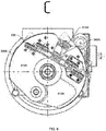
- FIG. 6 shows a side view C from FIG. 5 .
- springs 315A, 342A have been allowed to extend. The extension of the springs pulls the trigger away from the de-energized electromagnet via cable 230 and pushes brake pads 310A, 312A away from each other and towards braking surface 320A of the wheel.
- the trigger and cable guide 415A connected to the trigger
- the trigger is pulled down towards cable guides 415B and 415C via the cable routed to cable guide 415A.
- a first distance 426A is between cable guide 415A and cable guide 415B.
- a second distance 427A is between cable guide 415A and cable guide 415C.
- a third distance 426B is between cable guide 415A and cable guide 415B.
- a fourth distance 427B is between cable guide 415A and cable guide 415C.
- the third distance is less than the first distance. That is, the first distance is greater than the third distance.
- the fourth distance is less than the second distance. That is, the second distance is greater than the fourth distance.
- the trigger further includes a turning end 245.
- the turning end may be coaxial with an axis about which the trigger pivots relative to the electromagnet.
- the turning end includes a shaft having a hexagonal cross-section. This allows, for example, the trigger to be reset such as by grasping the turning end with a wrench to rotate the trigger back towards the electromagnet.
- the trigger may be reset by a motor connected to the turning end.
- FIG. 7 shows an enlarged view D from FIG. 2 of trigger turning end 245 having a hexagonal end according to one or more embodiments.
- FIG. 8 shows a schematic diagram of an emergency brake control system according to one or more embodiments.
- a general controller 805 a safety controller 810, robot sensors 815, a switch 820, and an electromagnet 825.
- the general controller and safety controller communicate with each other and receive signals from the sensors. As discussed, these signals may include information about speed, velocity, acceleration, location, obstacles, distance, and so forth.
- the switch is between the safety controller and the electromagnet and is controlled by the safety controller.
- the safety controller may enable the switch so that power is permitted to be passed via the switch to the electromagnet.
- the current causes the electromagnet to be energized so that the trigger via the magnetic material is held in place against the electromagnet.
- the switch is disabled and thus power is blocked from flowing to the electromagnet.
- the electromagnet is de-energized (e.g., magnetic field is lost) and the trigger is thus released from the electromagnet as the springs in the braking units extend and push the brake pads toward their respective braking surfaces.
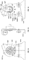
- FIG. 9 shows another schematic diagram of an emergency braking system 902.
- FIG. 9 shows the emergency braking system in a first position (e.g., non-emergency braking position or set state-electrical power on magnet is ON) according to one or more embodiments.
- FIG. 10 shows a schematic diagram of the emergency braking system in a second position (e.g., emergency braking position or triggered position-electrical power is OFF) according to one or more embodiments.
- safety controller 810 In the power circuit of the electromagnet 825 ( FIG. 8 ) installed switch 820 is managed by safety controller 810.
- the safety controller 810 receives information from the sensors of the robot 815 and analyzes it.
- the safety controller 810 communicates with the general controller 805 to monitor its operation.
- the safety controller 810 by the system owner includes criteria for determining the situation, which requires the use of emergency braking.
- the force acting on brake pads 910A, 915A ( FIG. 9 ) from the side of springs 920A, 925A is compensated by the force of the electromagnet acting on link 957. If necessary, the braking safety controller 810 ( FIG. 8 ) turns off the power of electromagnet 955 ( FIG. 9 ). As shown in the example of FIG. 10 , the release of the link 957 allows the brake pads to open under the action of force from the spring 920A, 925A (and corresponding springs 920B, 925B) and come into contact with an inner cylindrical surface of the wheel. Along with this, link 957 begins rotation 1028, under the action of force from a side of the springs 920A, 925A ( FIG. 9 ) (and corresponding springs 920B, 925B- FIG. 10 ).
- to bring the emergency braking system to the initial state it is required to turn on the electromagnet 955 and turn the link 957 before contact with it.
- Rotation is carried out using hexagon tip 245 ( FIG. 2 ). In some embodiments, this could be performed by a human operator, a robotized environment or by an additionally installed electrical motor, activated by robot controller in other embodiments.
- the first braking unit includes a first pair of brake pads including a first brake pad 910A and a second brake pad 915A, opposite the first brake pad, a first spring 920A and a second spring 925A, adjacent to or below the first spring.
- the first and second springs are positioned between ends 922A of the brake pads and opposite joints 923A about which the first and second brake pads may rotate, translate, or both.
- the first and second springs are biased to urge the first and second brake pads away from each other and towards a first braking surface of a first wheel.
- the first and second springs may be compression springs.
- a first synchronizing link 930A between the first and second brake pads and at the first spring helps to synchronize the movement of the brake pads so that each brake pad can move an equal (and opposite amount).
- the first braking unit forms a first drum brake.
- the first braking unit further includes a first cable guide 935A and a second cable guide 940A, opposite the first cable guide.
- the first and second cable guides are positioned between the first and second brake pads.
- the first cable guide may be connected to the first brake pad.
- the second cable guide may be connected to the second brake pad.
- a portion of a cable 945 is wrapped around the first and second cable guides.
- the second braking unit may be a mirror image of the first braking unit.
- the second braking unit includes a second pair of brake pads including a third brake pad 910B and a fourth brake pad 915B, opposite the third brake pad, a third spring 920B and a fourth spring 925B, adjacent to or below the third spring.
- the third and fourth springs are positioned between ends 922B of the brake pads and opposite joints 923B about which the third and fourth brake pads may rotate, translate, or both.
- the third and fourth springs are biased to urge the third and fourth brake pads away from each other and towards a second braking surface of a second wheel.
- the third and fourth springs may be compression springs.
- a second synchronizing link 930B between the third and fourth brake pads and at the third spring helps to synchronize the movement of the brake pads so that each brake pad can move an equal (and opposite) amount.
- the second braking unit forms a second drum brake.
- the second braking unit further includes a third cable guide 93 5B and a fourth cable guide 940B, opposite the third cable guide.
- the third and fourth cable guides are positioned between the third and fourth brake pads.
- the third cable guide may be connected to the third brake pad.
- the fourth cable guide may be connected to the fourth brake pad.
- Another portion of cable 945 is wrapped around the third and fourth cable guides.
- the trigger includes a cable guide 960A.
- Cable guides 960B and 960C are below cable guide 960A, between the first and second braking units, and are fixed relative to cable guide 960A.
- the cable guides can help change a direction of a force applied to the cable and provide a smooth routing of the cable to the trigger.
- the cable guides 960A-C lie in a first plane.
- Cable guides 935A and 940A of the first braking unit lie in a second plane, different from the first plane.
- Cable guides 93 5B and 940B of the second braking unit lie in a third plane, different from the first and second planes.
- the second and third planes are parallel to each other.
- the second and third planes are orthogonal to the first plane.
- a routing path of the cable is from the first braking unit to cable guide 960B to cable guide 960A to cable guide 960C and to the second braking unit.
- the cable passes under cable guide 960B, over cable guide 960A, and under cable guide 960C.
- a switch 965 passes power to the electromagnet which energizes the electromagnet.
- a magnetic field is created which attracts and holds the trigger against the electromagnet.
- a strength of the magnetic field is sufficient to overcome the energy stored in the first, second, third, and fourth springs so as to hold the trigger in the non-emergency braking position and thus the brake pads of the braking units away from their respective braking surfaces.
- FIG. 10 shows the emergency braking system in the second position (e.g., emergency braking position).
- the first braking unit has been omitted from the view in FIG. 10 .
- switch 965 has been disabled or opened.
- the electromagnet is de-energized and the magnetic field dissipates.
- the springs in the braking units e.g., springs 920B and 925B
- the springs in the braking units are permitted to extend and push 1010B, 1015B the respective brake pads against the respective braking surfaces of the wheels.
- the cable being wrapped around the cable guides (e.g., cable guides 935B and 940B), is pulled in a third direction 1020B, opposite direction 950B ( FIG. 9 ).
- a portion of the cable between cable guide 960A and 960C is pulled in a fourth direction 1025B towards cable guide 960C and is at an angle with respect to direction 1020B as the cable is wrapped about cable guide 960C.
- Cable guide 960A pivots from a position 1022A to a position 1022B as it is pulled down via the cable towards cable guide 960C.
- the trigger Since cable guide 960A is attached to trigger 957 (which is no longer held against the electromagnet because of the loss of the magnetic field), the trigger likewise pivots 1028 away from a position 1030A against the electromagnet to a position 1030B away from the electromagnet.
- FIG. 11 shows a side view of a braking unit 1105 of an emergency brake system according to one or more embodiments.
- the braking unit may be referred to as an emergency braking unit.
- the braking unit includes first and second brake pads 1110A, 1115A.
- the pads are movably connected by a joint 1120 at their first ends.
- a pair of springs 1125 are positioned at second ends, opposite the first ends.
- Each pad may include braking material on outside edges of the pads. The springs are biased to urge the brake pads away from each other.
- the first brake pad includes a first opening 1130A that includes a first cable guide 1135A, and a second cable guide 1140A.
- the second brake pad includes a second opening 1130B that includes a third cable guide 1135B, and a fourth cable guide 1140B.
- a cable guide may be referred to as a block or pulley.
- a portion of a cable may be wrapped around cable guides 1135A and 1135B.
- Another portion of the cable may be wrapped around cable guides 1140A and 1140B. Pulling the cable pulls the brake pads together and away from a braking surface of a wheel as the springs compress.
- FIG. 12 shows a front view of a brake activator 1205 according to one or more embodiments.
- FIG. 13 shows a side view of the brake activator shown in FIG. 12.
- FIG. 14 shows a rear view of the brake activator shown in FIG. 12.
- FIGs. 12-14 show the brake activator in a non-emergency braking position.
- the brake activator includes a bracket 1410 having a flange 1315 ( FIG. 13 ) at a bottom end so that the bracket can be attached to a frame of a robot.
- a link or trigger 1420 is pivotally connected to a top end of the bracket, and an electromagnet 1425 is fixedly connected next to the trigger. More particularly, the electromagnet is fixed to another bracket 1427 which, in turn, is connected to bracket 1410 at the top end of bracket 1410.
- the trigger includes a cable guide 1430A and a plate 1435 having a magnetic material that extends out from the trigger to face the electromagnet. Cable guides 1430B and 1430C are connected to the bracket 1410 below cable guide 1430A.
- Cable guides 1430A-C form vertices of a triangle.
- the trigger pivots about a shaft 1440.
- the bracket further includes a set of holes 1445 arranged about the shaft in an arc.
- a routing path of a cable may be from a first braking unit to cable guide 1430B to cable guide 1430A to cable guide 1430C to a second braking unit, opposite the first braking unit.
- bracket 1427 upon which the electromagnet is mounted includes a curved slot 1210.
- the curved slot exposes holes 1445 ( FIG. 14 ) in bracket 1410.
- the slot and corresponding holes allow the electromagnet to be repositioned relative to the trigger by repositioning bracket 1427 on bracket 1410.
- the electromagnet may be positioned by holding the bracket 1427 in a first position, inserting a bolt through a first hole 1415A ( FIG. 14 ) in bracket 1410 so that it extends into and out of curved slot 1210, and then fastening the bolt with a nut to secure the electromagnet in the first position.
- the electromagnet may be repositioned to a second position by, for example, removing the bolt and nut, holding bracket 1427 in a second position, different from the first position, inserting the bolt through a second hole 1415B (or optionally in first hole 1415A), and then retightening the nut to secure the electromagnet in the second position.
- the ability to reposition the electromagnet allows for adjustments to be made to obtain proper cable tension, accommodation of brake pads having varying thicknesses, accommodation for pad wear, and so forth.
- Shaft 1440 ( FIG. 14 ) about which the trigger pivots includes a turning interface 1220 ( FIG. 12 ).
- the turning interface includes an end having a hexagonal cross section.
- the trigger falls down and pivots away from the electromagnet as the trigger is pulled away from the electromagnet by the cable (e.g., pivots in a clockwise direction according to the view shown in FIG. 14 ).
- the turning interface allows the trigger to be turned and reset from the emergency braking position to the non-emergency braking position (e.g., turned in a counterclockwise direction according to the view shown in FIG. 14 ).
- resetting the trigger is a manual process.
- a user after re-energizing the electromagnet, may use a wrench to grasp the hexagonal end and rotate the trigger back towards the electromagnet.
- a motor may be connected to the hexagonal end to rotate the trigger back towards the electromagnet.
- FIG. 15 shows a system block diagram of a computer system 1505 used to execute the software of the present system described herein.
- the computer system may include an output interface 1507 (e.g., monitor), input interface 1515 (e.g., keyboard), and mass storage devices 1520.
- Computer system 1505 may further include subsystems such as central processor 1525, system memory 1530, input/output (I/O) controller 1535, display adapter 1540, serial or universal serial bus (USB) port 1545, network interface 1550, and speaker 1555.
- the system may also be used with computer systems with additional or fewer subsystems.
- a computer system could include more than one processor 1525 (i.e., a multiprocessor system) or a system may include a cache memory.
- Arrows such as 1560 represent the system bus architecture of computer system 1505. However, these arrows are illustrative of any interconnection scheme serving to link the subsystems. For example, speaker 1555 could be connected to the other subsystems through a port or have an internal direct connection to central processor 1525.
- the processor may include multiple processors or a multicore processor, which may permit parallel processing of information.
- Computer system 1505 shown in FIG. 15 is but an example of a computer system suitable for use with the present system. Other configurations of subsystems suitable for use with embodiments of the present disclosure will be readily apparent to one of ordinary skill in the art.
- Computer software products may be written in any of various suitable programming languages.
- the computer software product may be an independent application with data input and data display modules.
- the computer software products may be classes that may be instantiated as distributed objects.
- the computer software products may also be component software.
- An operating system for the system may be one of the Microsoft Windows®. family of systems (e.g., Windows Server), Linux, Mac OS X®, IRIX32, or IRIX64. Other operating systems may be used.
- Microsoft Windows is a trademark of Microsoft Corporation.
- the computer may be connected to a network and may interface to other computers using this network.
- the network may be an intranet, internet, or the Internet, among others.
- the network may be a wired network (e.g., using copper), telephone network, packet network, an optical network (e.g., using optical fiber), or a wireless network, or any combination of these.
- data and other information may be passed between the computer and components (or steps) of a system of embodiments of the disclosure using a wireless network using a protocol such as Wi-Fi (IEEE standards 802.11, 802.11a, 802.11b, 802.11e, 802.11g, 802.11i, 802.1 In, 802.11ac, and 802.11ad, just to name a few examples), near field communication (NFC), radio-frequency identification (RFID), mobile or cellular wireless.
- Wi-Fi IEEE standards 802.11, 802.11a, 802.11b, 802.11e, 802.11g, 802.11i, 802.1 In, 802.11ac, and 802.11ad, just to name a few examples
- NFC near field communication
- RFID radio-frequency identification
- signals from a computer may be transferred, at least in part, wirelessly to components or other computers.
- a computer-usable medium or computer-readable medium may be any physical medium that can contain or store the program for use by or in connection with the instruction execution system, apparatus or device.
- the computer-readable storage medium or computer-usable medium may be, but is not limited to, a random access memory (RAM), read-only memory (ROM), or a persistent store, such as a mass storage device, hard drives, CDROM, DVDROM, tape, erasable programmable read-only memory (EPROM or flash memory), or any magnetic, electromagnetic, optical, or electrical means or system, apparatus or device for storing information.
- RAM random access memory
- ROM read-only memory
- a persistent store such as a mass storage device, hard drives, CDROM, DVDROM, tape, erasable programmable read-only memory (EPROM or flash memory), or any magnetic, electromagnetic, optical, or electrical means or system, apparatus or device for storing information.
- the computer-readable storage medium or computer-usable medium may be any combination of these devices or even paper or another suitable medium upon which the program code is printed, as the program code can be electronically captured, via, for instance, optical scanning of the paper or other medium, then compiled, interpreted, or otherwise processed in a suitable manner, if necessary, and then stored in a computer memory.
- Applications, software programs or computer-readable instructions may be referred to as components or modules. Applications may be hardwired or hard coded in hardware or take the form of software executing on a general purpose computer or be hardwired or hard coded in hardware such that when the software is loaded into and/or executed by the computer, the computer becomes an apparatus for practicing embodiments of the disclosure.
Abstract
Description
- The present invention relates generally to robots, and more particularly to an emergency braking system for a mobile robot.
- Robots, such as automated guided vehicles (AGVs), are used in a variety of areas, including support for processing and handling throughout a facility or outside. Some specific applications of robots or AGVs include: 1) assembly, e.g., moving products through production processes; 2) kitting, e.g., collecting parts for assembly; 3) transportation, e.g., loading pallets and loose parts; 4) staging, e.g., delivering pallets for production processes; 5) warehousing, e.g., moving products from stretch wrappers to docks or storage; 6) order picking, e.g., moving ordered products to trailer-loading areas for distribution, and transporting a platform for a picker to place selected items upon; 7) parts/just-in-time (JIT) delivery, e.g., towing trailers of parts/materials to consumption points; 8) transfer/shuttle, e.g., transfer loads across high traffic aisles; 9) surveillance, e.g., if equipped with cameras and sensors.
- There is a need for an emergency braking system because AGVs can move at very high speeds and carry heavy loads. An AGV that malfunctions can present a danger to not just other equipment and property, but lives as well. An emergency braking system is desirable for AGVs operating in any number of different fields such as, but not limited to: automotive, beverage, chemicals, commercial printing, food, hospital, manufacturing, newspaper, paper, pharmaceutical, plastics, warehousing and distribution, and so forth.
- The subject matter discussed in the background section should not be assumed to be prior art merely as a result of its mention in the background section. Similarly, a problem mentioned in the background section or associated with the subject matter of the background section should not be assumed to have been previously recognized in the prior art. The subject matter in the background section merely represents different approaches, which in and of themselves may also be embodiments.
- In the following drawings like reference numerals designate like structural elements. Although the figures depict various examples, the one or more embodiments and implementations described herein are not limited to the examples depicted in the figures.
-
FIG. 1 shows a block diagram of a robot having an emergency braking system, according to one or more embodiments. -
FIG. 2 shows a front view of a robot having an emergency braking system with a trigger in an "ON" position, according to one or more embodiments. -
FIG. 3 shows a side view of the robot shown inFIG. 2 , according to one or more embodiments. -
FIG. 4 shows a rear view of the robot shown inFIG. 2 , according to one or more embodiments. -
FIG. 5 shows a rear view of the robot with the trigger in an "OFF" position, according to one or more embodiments. -
FIG. 6 shows a side view of the robot shown inFIG. 5 , according to one or more embodiments. -
FIG. 7 shows an enlarged front view of the trigger mechanism, according to one or more embodiments. -
FIG. 8 shows a schematic diagram of an emergency brake control system, according to one or more embodiments. -
FIG. 9 shows a schematic diagram of an emergency braking system mechanism in a first position, according to one or more embodiments. -
FIG. 10 shows a schematic diagram of the emergency braking system mechanism shown inFIG. 9 in a second position, according to one or more embodiments. -
FIG. 11 shows a side view of a braking pad assembly of an emergency braking unit, according to one or more embodiments. -
FIG. 12 shows a front view of a brake activator, according to one or more embodiments. -
FIG. 13 shows a side view of the brake activator shown inFIG. 12 , according to one or more embodiments. -
FIG. 14 shows a rear view of the brake activator shown inFIG. 12 , according to one or more embodiments. -
FIG. 15 shows a block diagram of a computer system suitable for use with a robot having an emergency braking system, according to one or more embodiments. - A detailed description of one or more embodiments is provided below along with accompanying figures that illustrate the principles of the described embodiments. While aspects of the disclosure are described in conjunction with such embodiment(s), it should be understood that it is not limited to any one embodiment. On the contrary, the scope is limited only by the claims and the embodiments encompass numerous alternatives, modifications, and equivalents. For the purpose of example, numerous specific details are set forth in the following description in order to provide a thorough understanding of the described embodiments, which may be practiced according to the claims without some or all of these specific details. For the purpose of clarity, technical material that is known in the technical fields related to the embodiments has not been described in detail so that the described embodiments are not unnecessarily obscured.
-
FIG. 1 shows a block diagram of amobile robot 105. The robot may be an automated guided vehicle (AGV). An AGV is a portable robot that follows along marked lines or wires on the floor, or uses radio waves, vision cameras, magnets, or lasers for navigation. This AGV can be used in industrial applications to transport heavy materials around a large industrial building, such as a factory or warehouse. - In an embodiment,
robot 105 includes ageneral controller 110 thatinterconnects sensors 115, apower supply 120, one ormore motors 125A, B, one ormore wheels 130A, B, asafety controller 135, anemergency braking system 140, and one or moreemergency braking units 142A, B for the one ormore wheels 130A, B, respectively. - The general controller is responsible for the overall operation of the robot. The general controller may include components such as a processor, memory, storage, network interface, and the like that are interconnected by a system bus. Programs, data, and other information may be stored in storage and read into memory for the processor to execute and process.
- Sensors may include navigation sensors, inertial sensors, inclinometers, accelerometers, range sensors, obstacle detectors, light sensors, cameras, acceleration sensors, gyroscopes, and location sensors (e.g., global positioning system (GPS) sensors) - just to name a few examples. These sensors generate signals that are passed to the general controller, safety controller, or both.
- The power supply may include a battery. The battery may be rechargeable or non-rechargeable. Examples of batteries include nickel cadmium batteries, nickel metal hydride batteries, lithium ion batteries, and sealed lead acid batteries. In another specific embodiment, the power supply can be a wall socket. For example, an electrical cord may be used to connect the robot to the wall socket. In another specific embodiment, power may be provided wirelessly such as via electromagnetic induction, magnetic resonance, or other wireless power transfer.
- The motors receive driving control signals from the general controller. These driving control signals can cause the robot to move forward, move backward, turn left, turn right, accelerate, decelerate, stop, and so forth. For example, power from the power supply is provided to the motors so as to generate a rotational force that moves the wheel. Thus, a
power path 145 may be from the power supply to the general controller and to each of the motors. - A robot may include a single wheel that is driven by a single motor. A robot may include two or more wheels driven by a single motor. A robot may include multiple wheels and multiple motors where each wheel is driven by a particular motor. In a specific embodiment, a motor also provides primary braking responsibilities to the wheel. That is, the motor is used to brake the wheel and stop the robot from moving.
- It is desirable, however, to have an emergency braking system. The emergency braking system can be used to brake the wheels and stop the robot in the event that there is an emergency. In an embodiment, the safety controller is connected to the emergency braking system and includes logic to determine whether there is an emergency. When there is an emergency, the emergency braking units can be activated via a brake activator of the emergency braking system to stop the wheels of the robot.
- In an embodiment, emergency braking refers to braking used to stop a vehicle, such as the mobile robot, in critical situations associated with a lack of time and distance. A developed mobile robot (or application of a robot) can be equipped with powerful motors that allow the necessary accelerations when moving with any load in a specified range. In the event of a failure in the control system, the robot may develop a dangerously high-level of kinetic energy. In a specific embodiment, under normal operating conditions, the robot performs braking using motors. But in an emergency situation, when reducing the kinetic energy of a robot using motor braking is not possible, the emergency braking system can be used to help prevent accidents.
- In a specific embodiment, the emergency braking system provides for a mechanical braking. More particularly, specific embodiments allow braking by mechanical locking of the wheels of the robot in cases where motor braking is not possible. This might happen in rare cases where, for example, the power circuit is damaged or the processor, controlling the motor has a software error. Without the emergency braking system, the mobile robot (e.g., AGV) could become a source of danger for humans and workshop equipment, especially if loaded.
- There are various types of brake systems, such as: mechanical, pneumatic, hydraulic, electric, and so forth. Specific types of brakes include disk brakes, drum brakes, tape brakes, and magnetic brakes (e.g., single disk electromagnetic brakes). Brake systems can be normally open or normally closed. For controlled braking, normally open brakes are usually applied. For transport technology equipment, as well as transport such as trains, normally closed brakes can be used. There can be normally closed hydraulic tape brakes. There can be normally closed shoe brakes. Aspects and principles of the emergency braking system, as described herein, can be applied to a variety of different brake types (e.g., drum brakes, disk brakes, and others).
- In a specific embodiment, there is an emergency braking system that provides reliable emergency braking of a wheeled logistic robot. The emergency braking system can be applied in other areas as well. In a specific embodiment, there are normally applied brakes, which are kept from being closed by a force acting from an electromagnet. The brakes are disabled until a supply voltage is applied to the magnet. If the control system makes a decision about an emergency situation that requires braking, the electromagnet turns off and the brakes block the wheels. Also, the wheels are blocked in case of a power failure of the system.
- In a specific embodiment, there is a
power path 150 from the power supply to the safety controller and ultimately to the emergency braking system. The power inpower path 150 energizes an electromagnet of the emergency braking system which, in turn, maintains the emergency braking units in a non-emergency braking mode in which the wheels are free to move (or stop) via the motors. If, for example, the power is interrupted such as by the safety controller determining that there is an emergency, an emergency braking mode is entered where the electromagnet is de-energized which in turn activates the emergency braking units to prevent the wheels from moving. -
FIG. 2 shows a front view of arobot 205 in which an emergency braking system may be implemented according to one or more embodiments. In a specific embodiment, this brake system includes brake pads (e.g., 310A, 312A-FIG. 3 ), equipped with blocks (e.g., 330A, 340A-FIG. 3 ). A block may be referred to as a cable guide or pulley. The pads may be installed with the possibility of rotation on the motor (e.g.,motor 220A-FIG. 2 ), which is mounted on aframe 215.Blocks FIG. 3 ) are covered by acable 230. The cable may be referred to as a wire.Cable 230 connects the brake pads of both wheels, while bending around blocks or cable guides 415A-C (FIG. 4 ).Springs FIG. 3 ) are installed between the pads.Springs pads wheel 210A (FIG. 2 ). For the synchronous extension of thepads motor 220A a synchronizing link 322 (FIG. 3 ) is mounted, against which thesprings Blocks FIG. 4 ) are installed on abracket 240, which is fixed on theframe 215.Block 415A is mounted on a link or trigger 235, which is fixed on thebracket 240 with the possibility of rotation. Also, in a specific embodiment, link (or trigger) 235 is equipped with a hexagonal end 245 (FIG. 2 ) for cocking and a platform of magnetic material. In the cocked state, the link or trigger 235 is held by an electromagnet 405 (FIG. 4 ) mounted on the link or trigger 235 (or more specifically mounted next to the link or trigger). The link or trigger 235 is attached with the possibility of adjustment to thebracket 240. - More particularly, in a specific embodiment, the robot shown in the example of
FIG. 2 includes a first or leftwheel 210A connected to a first end of aframe 215; a second orright wheel 210B, opposite the first wheel, and connected to a second end of the frame, opposite the first end of the frame; afirst motor 220A at the first end of the frame that drives the first wheel; asecond motor 220B at the second end of the frame that drives the second wheel; a firstemergency braking unit 225A at the first wheel; a secondemergency braking unit 225B at the second wheel; and acable 230 connecting the first and second emergency braking units to atrigger 235. - The trigger may be referred to as a link. The trigger is positioned between the first and second braking units and pivotally connected to the
bracket 240 which in turn is connected to the frame. - The cable may be referred to as a wire, line, or cord. Material of the cable may include steel (e.g., stainless steel), a polymer, carbon fiber, nylon, or any other suitable material. The cable may be a braided cable.
-
FIG. 3 shows a left side view A ofFIG. 2 . As shown in the example ofFIG. 3 , firstemergency braking unit 225A for the first wheel includes afirst brake pad 310A and afirst spring 315A that urges the first brake pad towards afirst braking surface 320A for the first wheel. - More specifically, the first brake pad is part of a pair of brake pads that includes a
second brake pad 312A. First andsecond brake pads second spring 342A next tofirst spring 315A.First spring 315A, along withsecond spring 342A, are opposite the first joint and between first andsecond brake pads second springs second brake pads first braking surface 320A for the first wheel. There can be afirst synchronizing link 322 between the first and second brake pads to synchronize the movement of the brake pads. - The first and second brake pads further include a set of blocks. A block may be referred to as a cable guide or pulley and can be used to change a direction of force of an attached cable. A block (e.g., cable guide or pulley) may include a groove in order to guide an attached cable. In particular, the first brake pad includes a
first opening 325A in which afirst cable guide 330A may be secured. The second brake pad includes asecond opening 335A in which asecond cable guide 340A may be secured. The cable is wrapped around the first and second cable guides. - The first opening in the first brake pad may further include a
third cable guide 345A. The second opening in the second brake pad may further include afourth cable guide 350A. Another portion of the cable may be wrapped around the third and fourth cable guides. - The cable can be pulled so as to pull the first and second brake pads together and away from the first braking surface. For example, in a specific embodiment, first and
second springs second brake pads second brake pads - In an embodiment, the second emergency braking unit for the second wheel is similar to the first emergency braking unit. For example, the second
emergency braking unit 225A for the second wheel includes a third brake pad and a third spring that urges a fourth brake pad towards a second braking surface for the second wheel. - More specifically, the third brake pad is part of a second pair of brake pads that includes a fourth brake pad. Third and fourth brake pads are connected at a second joint. The second joint may be a sliding joint. There can be a fourth spring next to the third spring. The third spring, along with fourth spring, is opposite the second joint and between the third and fourth brake pads. The third and fourth springs are biased or configured to urge third and fourth brake pads apart from each other and towards the second braking surface for the second wheel. There can be a second synchronizing link between the third and fourth brake pads to synchronize the movement of the third and fourth brake pads.
- The third and fourth brake pads further include a set of cable guides. In particular, the third brake pad includes a third opening in which a fifth cable guide may be secured. The fourth brake pad includes a fourth opening in which a sixth cable guide may be secured. Another portion of the cable may be wrapped around the fifth and sixth cable guides.
- The third opening in the third brake pad may further include a seventh cable guide. The fourth opening in the fourth brake pad may further include an eighth cable guide. Another portion of the cable may be wrapped around the seventh and eighth cable guides. Pulling the cable pulls the first and second brake pads of the first emergency braking unit together and away from the first braking surface for the first wheel. Since the cable is also connected to the second braking the unit, pulling the cable also pulls the third and fourth brake pads of the second emergency braking unit together and away from the second braking surface for the second wheel.
-
FIG. 4 shows a rear view B fromFIG. 3 . As shown in the example ofFIG. 4 ,bracket 240 includes trigger or link 235 pivotally connected to the bracket. Theelectromagnet 405 is fixedly connected to the bracket. - An electromagnet is a type of magnet in which the magnetic field is produced by an electric current. The magnetic field disappears when the current is turned off. An electromagnet may include wire wound into a coil. A current through the wire creates a magnetic field which is concentrated in a hole in the center of the coil. The wire turns are often wound around a magnetic core made from a ferromagnetic or ferrimagnetic material such as iron. The magnetic field can be changed by controlling the amount of electric current in the winding. An electromagnet, unlike a permanent magnet, requires a continuous supply of current to maintain the magnetic field.
- The trigger includes a
magnetic material 410. When the electromagnet is energized (e.g., supplied with power) a magnetic force is produced which causes the trigger to be retained against the electromagnet via the magnetic material. - The trigger includes a
cable guide 415A. Cable guides 415B and 415C are connected to the bracket and belowcable guide 415A.Cable guide 415B is positioned closer tosecond wheel 210B thanfirst wheel 210A.Cable guide 415C is positioned closer tofirst wheel 210A thansecond wheel 210B. A routing path of the cable is fromfirst braking unit 225A (where the cable is wrapped around the cable guides of the pair of brake pads in the first braking unit) to the link tosecond braking unit 225B (where the cable is wrapped around the cable guides of the pair of brake pads in the second braking unit). More particularly, the routing path of the cable is fromfirst braking unit 225A, to and undercable guide 415C, to and overcable guide 415A, to and undercable guide 415B, and tosecond braking unit 225B. -
FIG. 4 shows the trigger in a first position. The first position may be referred to as an "ON" position, cocked state, or a non-emergency braking position. In the first position, the electromagnet is energized and the trigger is retained or held against the electromagnet. The retaining of the trigger pulls the cable which, in turn, pulls the brake pads of the first and second braking units together and away from the respective braking surfaces of the first and second wheels. -
FIG. 5 shows trigger 235 in a second position. The second position may be referred to as an "OFF" position, un-cocked state, or an emergency braking position. In the second position, the electromagnet is de-energized. The loss of power to the electromagnet allows the link to be released from the electromagnet as the springs in the first and second braking units are allowed to extend thereby pushing the brake pads towards and against the respective first and second braking surfaces and pulling the cable which pulls the trigger pivotally away 510 fromelectromagnet 405. - For example,
FIG. 6 shows a side view C fromFIG. 5 . As shown in the example ofFIG. 5 , springs 315A, 342A have been allowed to extend. The extension of the springs pulls the trigger away from the de-energized electromagnet viacable 230 and pushesbrake pads braking surface 320A of the wheel. In other words, as shown inFIG. 5 , the trigger (andcable guide 415A connected to the trigger) is pulled down towards cable guides 415B and 415C via the cable routed tocable guide 415A. - More particularly, when the trigger is in the non-emergency braking position (
FIG. 4 ), afirst distance 426A is betweencable guide 415A andcable guide 415B. Asecond distance 427A is betweencable guide 415A andcable guide 415C. - When the trigger is in the emergency braking position (
FIG. 5 ), athird distance 426B is betweencable guide 415A andcable guide 415B. A fourth distance 427B is betweencable guide 415A andcable guide 415C. The third distance is less than the first distance. That is, the first distance is greater than the third distance. The fourth distance is less than the second distance. That is, the second distance is greater than the fourth distance. - Referring back now to
FIG. 2 , in a specific embodiment, the trigger further includes a turningend 245. The turning end may be coaxial with an axis about which the trigger pivots relative to the electromagnet. In a specific embodiment, the turning end includes a shaft having a hexagonal cross-section. This allows, for example, the trigger to be reset such as by grasping the turning end with a wrench to rotate the trigger back towards the electromagnet. In another specific embodiment, the trigger may be reset by a motor connected to the turning end. -
FIG. 7 shows an enlarged view D fromFIG. 2 oftrigger turning end 245 having a hexagonal end according to one or more embodiments. -
FIG. 8 shows a schematic diagram of an emergency brake control system according to one or more embodiments. As shown in the example ofFIG. 8 , there is ageneral controller 805, asafety controller 810,robot sensors 815, aswitch 820, and anelectromagnet 825. The general controller and safety controller communicate with each other and receive signals from the sensors. As discussed, these signals may include information about speed, velocity, acceleration, location, obstacles, distance, and so forth. - The switch is between the safety controller and the electromagnet and is controlled by the safety controller. For example, the safety controller may enable the switch so that power is permitted to be passed via the switch to the electromagnet. The current causes the electromagnet to be energized so that the trigger via the magnetic material is held in place against the electromagnet. When the safety controller determines that emergency braking is needed or the robot happens to lose power, the switch is disabled and thus power is blocked from flowing to the electromagnet. The electromagnet is de-energized (e.g., magnetic field is lost) and the trigger is thus released from the electromagnet as the springs in the braking units extend and push the brake pads toward their respective braking surfaces.
-
FIG. 9 shows another schematic diagram of anemergency braking system 902.FIG. 9 shows the emergency braking system in a first position (e.g., non-emergency braking position or set state-electrical power on magnet is ON) according to one or more embodiments.FIG. 10 shows a schematic diagram of the emergency braking system in a second position (e.g., emergency braking position or triggered position-electrical power is OFF) according to one or more embodiments. - In the power circuit of the electromagnet 825 (
FIG. 8 ) installedswitch 820 is managed bysafety controller 810. Thesafety controller 810 receives information from the sensors of therobot 815 and analyzes it. In addition, thesafety controller 810 communicates with thegeneral controller 805 to monitor its operation. Thesafety controller 810 by the system owner includes criteria for determining the situation, which requires the use of emergency braking. - The force acting on
brake pads FIG. 9 ) from the side ofsprings link 957. If necessary, the braking safety controller 810 (FIG. 8 ) turns off the power of electromagnet 955 (FIG. 9 ). As shown in the example ofFIG. 10 , the release of thelink 957 allows the brake pads to open under the action of force from thespring corresponding springs rotation 1028, under the action of force from a side of thesprings FIG. 9 ) (andcorresponding springs FIG. 10 ). - In a specific embodiment, to bring the emergency braking system to the initial state, it is required to turn on the
electromagnet 955 and turn thelink 957 before contact with it. Rotation is carried out using hexagon tip 245 (FIG. 2 ). In some embodiments, this could be performed by a human operator, a robotized environment or by an additionally installed electrical motor, activated by robot controller in other embodiments. - More particularly, referring now to
FIG. 9 , in a specific embodiment, there is afirst braking unit 905A and asecond braking unit 905B. The first braking unit includes a first pair of brake pads including afirst brake pad 910A and asecond brake pad 915A, opposite the first brake pad, afirst spring 920A and asecond spring 925A, adjacent to or below the first spring. The first and second springs are positioned between ends 922A of the brake pads andopposite joints 923A about which the first and second brake pads may rotate, translate, or both. The first and second springs are biased to urge the first and second brake pads away from each other and towards a first braking surface of a first wheel. The first and second springs may be compression springs. Afirst synchronizing link 930A between the first and second brake pads and at the first spring helps to synchronize the movement of the brake pads so that each brake pad can move an equal (and opposite amount). In a specific embodiment, the first braking unit forms a first drum brake. - The first braking unit further includes a
first cable guide 935A and asecond cable guide 940A, opposite the first cable guide. The first and second cable guides are positioned between the first and second brake pads. The first cable guide may be connected to the first brake pad. The second cable guide may be connected to the second brake pad. A portion of acable 945 is wrapped around the first and second cable guides. Thus, pulling the cable in afirst direction 950A pulls the first and second brake pads together away from the first braking surface as the first and second springs are compressed. - The second braking unit may be a mirror image of the first braking unit. For example, the second braking unit includes a second pair of brake pads including a
third brake pad 910B and afourth brake pad 915B, opposite the third brake pad, athird spring 920B and afourth spring 925B, adjacent to or below the third spring. The third and fourth springs are positioned between ends 922B of the brake pads andopposite joints 923B about which the third and fourth brake pads may rotate, translate, or both. The third and fourth springs are biased to urge the third and fourth brake pads away from each other and towards a second braking surface of a second wheel. The third and fourth springs may be compression springs. Asecond synchronizing link 930B between the third and fourth brake pads and at the third spring helps to synchronize the movement of the brake pads so that each brake pad can move an equal (and opposite) amount. In a specific embodiment, the second braking unit forms a second drum brake. - The second braking unit further includes a third cable guide 93 5B and a
fourth cable guide 940B, opposite the third cable guide. The third and fourth cable guides are positioned between the third and fourth brake pads. The third cable guide may be connected to the third brake pad. The fourth cable guide may be connected to the fourth brake pad. Another portion ofcable 945 is wrapped around the third and fourth cable guides. Thus, pulling the cable in a second direction 950B, oppositefirst direction 950A, pulls the third and fourth brake pads together away from the second braking surface as the third and fourth springs are compressed. - Between the first and second braking units is an
electromagnet 955 and a pivotally connected link or trigger 957 having a plate or surface ofmagnetic material 958. In other words, the trigger can pivot with respect to or away from the electromagnet. The trigger includes acable guide 960A. Cable guides 960B and 960C are belowcable guide 960A, between the first and second braking units, and are fixed relative tocable guide 960A. The cable guides can help change a direction of a force applied to the cable and provide a smooth routing of the cable to the trigger. AlthoughFIG. 9 shows three cable guides (960A-C) between the first and second braking units, it should be appreciated that a number of cable guides, a position of cable guides, or both can vary depending on factors such as the design of the first and second braking units, location of the trigger, and so forth. In a specific embodiment, the cable guides 960A-C lie in a first plane. Cable guides 935A and 940A of the first braking unit lie in a second plane, different from the first plane. Cable guides 93 5B and 940B of the second braking unit lie in a third plane, different from the first and second planes. The second and third planes are parallel to each other. The second and third planes are orthogonal to the first plane. - A routing path of the cable is from the first braking unit to
cable guide 960B to cable guide 960A tocable guide 960C and to the second braking unit. In particular, the cable passes undercable guide 960B, overcable guide 960A, and undercable guide 960C. - A
switch 965 passes power to the electromagnet which energizes the electromagnet. A magnetic field is created which attracts and holds the trigger against the electromagnet. A strength of the magnetic field is sufficient to overcome the energy stored in the first, second, third, and fourth springs so as to hold the trigger in the non-emergency braking position and thus the brake pads of the braking units away from their respective braking surfaces. -
FIG. 10 shows the emergency braking system in the second position (e.g., emergency braking position). For purposes of clarity, the first braking unit has been omitted from the view inFIG. 10 . As shown in the example ofFIG. 10 ,switch 965 has been disabled or opened. Once power toelectromagnet 955 is terminated, the electromagnet is de-energized and the magnetic field dissipates. The springs in the braking units (e.g., springs 920B and 925B) are permitted to extend and push 1010B, 1015B the respective brake pads against the respective braking surfaces of the wheels. The cable, being wrapped around the cable guides (e.g., cable guides 935B and 940B), is pulled in athird direction 1020B, opposite direction 950B (FIG. 9 ). A portion of the cable betweencable guide fourth direction 1025B towardscable guide 960C and is at an angle with respect todirection 1020B as the cable is wrapped aboutcable guide 960C.Cable guide 960A pivots from aposition 1022A to aposition 1022B as it is pulled down via the cable towardscable guide 960C. Sincecable guide 960A is attached to trigger 957 (which is no longer held against the electromagnet because of the loss of the magnetic field), the trigger likewise pivots 1028 away from aposition 1030A against the electromagnet to aposition 1030B away from the electromagnet. -
FIG. 11 shows a side view of abraking unit 1105 of an emergency brake system according to one or more embodiments. The braking unit may be referred to as an emergency braking unit. As shown in the example ofFIG. 11 , the braking unit includes first andsecond brake pads springs 1125 are positioned at second ends, opposite the first ends. Each pad may include braking material on outside edges of the pads. The springs are biased to urge the brake pads away from each other. - The first brake pad includes a
first opening 1130A that includes afirst cable guide 1135A, and asecond cable guide 1140A. The second brake pad includes asecond opening 1130B that includes athird cable guide 1135B, and afourth cable guide 1140B. As discussed, a cable guide may be referred to as a block or pulley. A portion of a cable may be wrapped around cable guides 1135A and 1135B. Another portion of the cable may be wrapped around cable guides 1140A and 1140B. Pulling the cable pulls the brake pads together and away from a braking surface of a wheel as the springs compress. -
FIG. 12 shows a front view of abrake activator 1205 according to one or more embodiments.FIG. 13 shows a side view of the brake activator shown inFIG. 12. FIG. 14 shows a rear view of the brake activator shown inFIG. 12. FIGs. 12-14 show the brake activator in a non-emergency braking position. - Referring now to
FIG. 14 , the brake activator includes abracket 1410 having a flange 1315 (FIG. 13 ) at a bottom end so that the bracket can be attached to a frame of a robot. A link ortrigger 1420 is pivotally connected to a top end of the bracket, and anelectromagnet 1425 is fixedly connected next to the trigger. More particularly, the electromagnet is fixed to anotherbracket 1427 which, in turn, is connected tobracket 1410 at the top end ofbracket 1410. The trigger includes acable guide 1430A and aplate 1435 having a magnetic material that extends out from the trigger to face the electromagnet. Cable guides 1430B and 1430C are connected to thebracket 1410 belowcable guide 1430A. Cable guides 1430A-C form vertices of a triangle. The trigger pivots about ashaft 1440. The bracket further includes a set ofholes 1445 arranged about the shaft in an arc. As discussed, a routing path of a cable may be from a first braking unit tocable guide 1430B tocable guide 1430A tocable guide 1430C to a second braking unit, opposite the first braking unit. - Referring now to
FIG. 12 ,bracket 1427 upon which the electromagnet is mounted includes acurved slot 1210. The curved slot exposes holes 1445 (FIG. 14 ) inbracket 1410. The slot and corresponding holes allow the electromagnet to be repositioned relative to the trigger byrepositioning bracket 1427 onbracket 1410. For example, the electromagnet may be positioned by holding thebracket 1427 in a first position, inserting a bolt through afirst hole 1415A (FIG. 14 ) inbracket 1410 so that it extends into and out ofcurved slot 1210, and then fastening the bolt with a nut to secure the electromagnet in the first position. The electromagnet may be repositioned to a second position by, for example, removing the bolt and nut, holdingbracket 1427 in a second position, different from the first position, inserting the bolt through asecond hole 1415B (or optionally infirst hole 1415A), and then retightening the nut to secure the electromagnet in the second position. The ability to reposition the electromagnet allows for adjustments to be made to obtain proper cable tension, accommodation of brake pads having varying thicknesses, accommodation for pad wear, and so forth. - Shaft 1440 (
FIG. 14 ) about which the trigger pivots includes a turning interface 1220 (FIG. 12 ). In a specific embodiment, the turning interface includes an end having a hexagonal cross section. When an emergency is detected or the electromagnet otherwise loses power, the trigger falls down and pivots away from the electromagnet as the trigger is pulled away from the electromagnet by the cable (e.g., pivots in a clockwise direction according to the view shown inFIG. 14 ). The turning interface allows the trigger to be turned and reset from the emergency braking position to the non-emergency braking position (e.g., turned in a counterclockwise direction according to the view shown inFIG. 14 ). In a specific embodiment, resetting the trigger is a manual process. For example, a user, after re-energizing the electromagnet, may use a wrench to grasp the hexagonal end and rotate the trigger back towards the electromagnet. In another specific embodiment, a motor may be connected to the hexagonal end to rotate the trigger back towards the electromagnet. - Below are some benefits of the emergency braking system.
- 1) Embodiments help to ensure maximum response of mechanical parts of the brake system by using mechanical compression springs.
- 2) Embodiments improve the reliability of the emergency brake system by using steel cables and compression springs, instead of gases and hydraulic fluids.
- 3) Embodiments provide for operation of the system using only the electrical energy of the batteries and the mechanical energy stored in the springs.
- 4) Embodiments help to ensure uniform activation of the brake pads of both wheels since the brakes are initiated by one trigger mechanism and are controlled by one cable (e.g., steel or polymer cable).
- 5) Embodiments help to prevent the launching of the wheeled robot in the event that the power supply voltage of the robot has disappeared as a result of an abnormal situation.
- Principles and aspects of an emergency braking system as described herein may be applied to any type of moving objects, equipped with wheels or other vehicle propulsion system (e.g., continuous track or tank treads).
-
FIG. 15 shows a system block diagram of acomputer system 1505 used to execute the software of the present system described herein. The computer system may include an output interface 1507 (e.g., monitor), input interface 1515 (e.g., keyboard), andmass storage devices 1520.Computer system 1505 may further include subsystems such ascentral processor 1525,system memory 1530, input/output (I/O)controller 1535,display adapter 1540, serial or universal serial bus (USB)port 1545,network interface 1550, andspeaker 1555. The system may also be used with computer systems with additional or fewer subsystems. For example, a computer system could include more than one processor 1525 (i.e., a multiprocessor system) or a system may include a cache memory. - Arrows such as 1560 represent the system bus architecture of
computer system 1505. However, these arrows are illustrative of any interconnection scheme serving to link the subsystems. For example,speaker 1555 could be connected to the other subsystems through a port or have an internal direct connection tocentral processor 1525. The processor may include multiple processors or a multicore processor, which may permit parallel processing of information.Computer system 1505 shown inFIG. 15 is but an example of a computer system suitable for use with the present system. Other configurations of subsystems suitable for use with embodiments of the present disclosure will be readily apparent to one of ordinary skill in the art. - Computer software products may be written in any of various suitable programming languages. The computer software product may be an independent application with data input and data display modules. Alternatively, the computer software products may be classes that may be instantiated as distributed objects. The computer software products may also be component software.
- An operating system for the system may be one of the Microsoft Windows®. family of systems (e.g., Windows Server), Linux, Mac OS X®, IRIX32, or IRIX64. Other operating systems may be used. Microsoft Windows is a trademark of Microsoft Corporation.
- Furthermore, the computer may be connected to a network and may interface to other computers using this network. The network may be an intranet, internet, or the Internet, among others. The network may be a wired network (e.g., using copper), telephone network, packet network, an optical network (e.g., using optical fiber), or a wireless network, or any combination of these. For example, data and other information may be passed between the computer and components (or steps) of a system of embodiments of the disclosure using a wireless network using a protocol such as Wi-Fi (IEEE standards 802.11, 802.11a, 802.11b, 802.11e, 802.11g, 802.11i, 802.1 In, 802.11ac, and 802.11ad, just to name a few examples), near field communication (NFC), radio-frequency identification (RFID), mobile or cellular wireless. For example, signals from a computer may be transferred, at least in part, wirelessly to components or other computers.
- It should be appreciated that the described embodiments can be implemented in numerous ways, including as a process, an apparatus, a system, a device, a method, or a computer-readable medium such as a computer-readable storage medium containing computer-readable instructions or computer program code, or as a computer program product, comprising a computer-usable medium having a computer-readable program code embodied therein. In the context of this disclosure, a computer-usable medium or computer-readable medium may be any physical medium that can contain or store the program for use by or in connection with the instruction execution system, apparatus or device. For example, the computer-readable storage medium or computer-usable medium may be, but is not limited to, a random access memory (RAM), read-only memory (ROM), or a persistent store, such as a mass storage device, hard drives, CDROM, DVDROM, tape, erasable programmable read-only memory (EPROM or flash memory), or any magnetic, electromagnetic, optical, or electrical means or system, apparatus or device for storing information. Alternatively or additionally, the computer-readable storage medium or computer-usable medium may be any combination of these devices or even paper or another suitable medium upon which the program code is printed, as the program code can be electronically captured, via, for instance, optical scanning of the paper or other medium, then compiled, interpreted, or otherwise processed in a suitable manner, if necessary, and then stored in a computer memory. Applications, software programs or computer-readable instructions may be referred to as components or modules. Applications may be hardwired or hard coded in hardware or take the form of software executing on a general purpose computer or be hardwired or hard coded in hardware such that when the software is loaded into and/or executed by the computer, the computer becomes an apparatus for practicing embodiments of the disclosure. Applications may also be downloaded, in whole or in part, through the use of a software development kit or toolkit that enables the creation and implementation of the described embodiments. In this specification, these implementations, or any other form that embodiments of the disclosure may take, may be referred to as techniques. In general, the order of the steps of disclosed processes may be altered within the scope of the disclosure. Aspects of the one or more embodiments described herein may be implemented on one or more computers executing software instructions, and the computers may be networked in a client-server arrangement or similar distributed computer network.
- Disclosed embodiments include those set out in the following clauses:
- 1. A robot comprising: a frame; a first wheel coupled to the frame; a first braking unit, coupled to the frame, and comprising a first brake pad, and a first spring that urges the first brake pad towards a first braking surface for the first wheel; an electromagnet; a trigger, pivotally coupled relative to the electromagnet, and comprising a magnetic surface; and a cable, coupled to the first braking unit and routed to the trigger, wherein when the electromagnet is energized, the trigger is retained against the electromagnet by the magnetic surface and pulls the cable which pulls the first brake pad away from the first braking surface, and wherein when the electromagnet is de-energized, the trigger is released from the electromagnet as the first spring is allowed to extend which pushes the first brake pad against the first braking surface and pulls the cable which pulls the trigger pivotally away from the electromagnet.
- 2. The robot of clause 1 comprising: a first cable guide coupled to the trigger; and a second cable guide coupled below the first cable guide, wherein a routing path of the cable is from the first braking unit to the second cable guide, and to the first cable guide, and wherein when the electromagnet is de-energized, the first cable guide is pulled towards the second cable guide by the cable as the trigger is released and pivots away from the electromagnet.
- 3. The robot of clause 1 comprising: a first cable guide coupled to the trigger; and a second cable guide coupled below the first cable guide, wherein a routing path of the cable is from the first braking unit to the second cable guide, and to the first cable guide, and wherein when the electromagnet is energized, a first distance is between the first and second cable guides, wherein when the electromagnet is de-energized, a second distance is between the first and second cable guides, and wherein the second distance is less than the first distance.
- 4. The robot of clause 1 comprising a turning end located at a pivot point of the trigger to allow the trigger to be rotated towards the electromagnet.
- 5. The robot of clause 1 comprising: a switch, coupled between the electromagnet and a power supply, wherein in a first mode, the switch passes power from the power supply to the electromagnet, thereby energizing the electromagnet to retain the trigger against the electromagnet, and wherein in a second mode, the switch disconnects the power, thereby de-energizing the electromagnet and allowing the trigger to be released from the electromagnet.
- 6. The robot of clause 1 comprising: a safety controller comprising logic to determine when the trigger should be released from the electromagnet; and a switch, coupled between the electromagnet and the safety controller, wherein the safety controller controls the switch such that in a non-emergency braking mode, the switch passes power to the electromagnet, thereby energizing the electromagnet to retain the trigger against the electromagnet, and in an emergency braking mode, the switch is disabled thereby disconnecting power to the electromagnet and allowing the trigger to be released from the electromagnet.
- 7. The robot of clause 1 comprising: a motor, coupled to the frame, that provides braking to the first wheel during a non-emergency braking mode, wherein when the motor is disabled during an emergency braking mode, the electromagnet is de-energized thereby allowing the trigger to be released and the first brake pad to push against the first braking surface.
- 8. The robot of clause 1 comprising: a second wheel, coupled to the frame, opposite the first wheel; a second braking unit, coupled to the frame, opposite the first braking unit, and comprising a second brake pad, and a second spring that urges the second brake pad towards a second braking surface for the second wheel, the second braking unit being coupled to the cable, and the trigger being between the first and second braking units, wherein when the electromagnet is energized, the trigger pulls the cable which pulls the second brake pad away from the second braking surface, along with pulling the first brake pad away from the first braking surface, and wherein when the electromagnet is de-energized, the second spring is allowed to extend which pushes the second brake pad against the second braking surface for the second wheel, while the first spring also extends to push the first brake pad against the first braking surface for the first wheel.
- 9. The robot of clause 1 comprising: a second wheel, coupled to the frame, opposite the first wheel; a second braking unit, coupled to the frame, opposite the first braking unit, and comprising a second brake pad, and a second spring that urges the second brake pad towards a second braking surface for the second wheel, the second braking unit being coupled to the cable, and the trigger being between the first and second braking units; a first cable guide coupled to the trigger; a second cable guide, coupled below the first cable guide, and positioned between the first and second braking units; a third cable guide, coupled below the first cable guide, and positioned between the first and second braking units, wherein a routing path of the cable is from the first braking unit to the second cable guide, to the first cable guide, to the third cable guide, and to the second braking unit, wherein when the electromagnet is energized, a first distance is between the first and second cable guides, and a second distance is between the first and third cable guides, wherein when the electromagnet is de-energized, a third distance is between the first and second cable guides, and a fourth distance is between the first and third cable guides, and wherein the first distance is greater than the third distance, and the second distance is greater than the fourth distance.
- 10. The robot of clause 1 comprising: a first motor, coupled to the frame, that provides braking to the first wheel during a non-emergency braking mode; a second wheel, coupled to the frame, opposite the first wheel; a second braking unit, coupled to the frame, and comprising a second brake pad, and a second spring that urges the second brake pad towards a second braking surface for the second wheel, the second braking unit being coupled to the cable; and a second motor, coupled to the frame, that provides braking to the second wheel during the non-emergency braking mode, wherein a routing path of the cable is from the first braking unit to the trigger to the second braking unit, wherein during the non-emergency braking mode, the electromagnet is energized and the trigger pulls the cable which pulls the first brake pad away from the first braking surface, and the second brake pad away from the second braking surface, the braking to the first wheel thereby being provided by the first motor, and the braking to the second wheel thereby being provided by the second motor, and wherein during an emergency braking mode, the electromagnet is de-energized and the trigger is released as the first spring urges the first brake pad towards the first braking surface, and the second spring urges the second brake pad towards the second braking surface.
- 11. The robot of clause 1 comprising: a second wheel coupled to the frame; a second braking unit, coupled to the frame, and comprising a second brake pad, and a second spring that urges the second brake pad towards a second braking surface for the second wheel, the second braking unit being coupled to the cable; a bracket, coupled to the frame, and to which the trigger is pivotally coupled, the bracket being between the first and second braking units; a first cable guide coupled to the trigger; a second cable guide, coupled to the bracket and below the first cable guide; and a third cable guide, coupled to the bracket and below the first cable guide, wherein a routing path of the cable is from the first braking unit, towards and under the second cable guide, to and above the first cable guide, towards and under the third cable guide, and to the second braking unit.
- 12. The robot of clause 1 comprising: a second wheel coupled to the frame; a second braking unit, coupled to the frame, and comprising a second brake pad, and a second spring that urges the second brake pad towards a second braking surface for the second wheel, the second braking unit being coupled to the cable, and a routing path of the cable being from the first braking unit, to the trigger, and to the second braking unit; a safety controller comprising logic to determine when the trigger should be released from the electromagnet; and a switch, coupled between the electromagnet and the safety controller, wherein the safety controller controls the switch such that in a non-emergency braking mode, the switch passes power to the electromagnet, thereby energizing the electromagnet to retain the trigger against the electromagnet and pull, via the cable, the first brake pad away from the first braking surface, and the second brake pad away from the second braking surface, and in an emergency braking mode, the switch is disabled thereby disconnecting power to the electromagnet and allowing the trigger to be pulled away from the electromagnet, via the cable, as the first spring extends to urge the first brake pad towards the first braking surface for the first wheel, and as the second spring extends to urge the second brake pad towards the second braking surface for the second wheel.
- 13. The robot of clause 1 comprising: a first motor, coupled to the frame, that provides braking to the first wheel during a non-emergency braking mode; a second wheel coupled to the frame; a second motor, coupled to the frame, that provides braking to the second wheel during the non-emergency braking mode; a second braking unit, coupled to the frame, and comprising a second brake pad, and a second spring that urges the second brake pad towards a second braking surface for the second wheel; a bracket, coupled to the frame, and to which the trigger is pivotally coupled, and the electromagnet fixedly coupled, the bracket being between the first and second braking units; a first cable guide coupled to the trigger; a second cable guide, coupled to the bracket and below the first cable guide; a third cable guide, coupled to the bracket and below the first cable guide, the second cable guide being closer to one of the first or second braking units, and the third cable guide being closer to another of the first or second braking units, a path of the cable being from the first braking unit to the second cable guide, up towards the first cable guide, down towards the third cable guide, and to the second braking unit; a safety controller comprising logic to determine when an emergency braking mode should be entered; a switch, coupled between the electromagnet and the safety controller, wherein the safety controller controls the switch such that in the non-emergency braking mode, the switch passes power to the electromagnet to energize the electromagnet and retain the trigger against the electromagnet, thereby pulling the cable which pulls the first brake pad away from the first braking surface, and the second brake pad away from the second braking surface, and in the emergency braking mode, the switch disconnects power to the electromagnet to de-energize the electromagnet and allow the trigger to be pivoted away from the electromagnet by the cable as the first spring extends to urge the first brake pad against the first braking surface, and as the second spring extends to urge the second brake pad against the second braking surface; and a turning interface on the trigger to allow the magnetic surface of the trigger to be rotated towards the electromagnet, which pulls the cable and thereby the first brake pad away from the first braking surface, and the second brake pad away from the second braking surface.
- 14. The robot of clause 13, comprising a third motor, coupled to the turning interface, to rotate the trigger towards the electromagnet; or comprising a battery to supply the power.
- 15. The robot of clause 2 wherein the first and second cable guides comprise a groove to guide the cable
- In the description above and throughout, numerous specific details are set forth in order to provide a thorough understanding of an embodiment of this disclosure. It will be evident, however, to one of ordinary skill in the art, that an embodiment may be practiced without these specific details. In other instances, well-known structures and devices are shown in block diagram form to facilitate explanation. The description of the preferred embodiments is not intended to limit the scope of the claims appended hereto. Further, in the methods disclosed herein, various steps are disclosed illustrating some of the functions of an embodiment. These steps are merely examples, and are not meant to be limiting in any way. Other steps and functions may be contemplated without departing from this disclosure or the scope of an embodiment. Other embodiments include systems and non-volatile media products that execute, embody or store processes that implement the methods described above.
Claims (15)
- A robot comprising:a frame;a first wheel coupled to the frame;a first braking unit, coupled to the frame, and comprising a first brake pad, and a first spring that urges the first brake pad towards a first braking surface for the first wheel;an electromagnet;a trigger, pivotally coupled relative to the electromagnet, and comprising a magnetic surface; anda cable, coupled to the first braking unit and routed to the trigger, wherein when the electromagnet is energized, the trigger is retained against the electromagnet by the magnetic surface and pulls the cable which pulls the first brake pad away from the first braking surface, andwherein when the electromagnet is de-energized, the trigger is released from the electromagnet as the first spring is allowed to extend which pushes the first brake pad against the first braking surface and pulls the cable which pulls the trigger pivotally away from the electromagnet.
- The robot of claim 1 comprising:a first cable guide coupled to the trigger; anda second cable guide, wherein a routing path of the cable is from the first braking unit to the second cable guide, and to the first cable guide, andwherein when the electromagnet is de-energized, the first cable guide is pulled towards the second cable guide by the cable as the trigger is released and pivots away from the electromagnet.
- The robot of claim 1 comprising:a first cable guide coupled to the trigger; anda second cable guide, wherein a routing path of the
cable is from the first braking unit to the second cable guide, and to the first cable guide, andwherein when the electromagnet is energized, a first distance is between the first and second cable guides,wherein when the electromagnet is de-energized, a second distance is between the first and second cable guides, andwherein the second distance is less than the first distance. - The robot of claim 1 comprising a turning end located at a pivot point of the trigger to allow the trigger to be rotated towards the electromagnet.
- The robot of claim 1 comprising:a switch, coupled between the electromagnet and a power supply, wherein in a first mode, the switch passes power from the power supply to the electromagnet, thereby energizing the electromagnet to retain the trigger against the electromagnet, andwherein in a second mode, the switch disconnects the power, thereby de-energizing the electromagnet and allowing the trigger to be released from the electromagnet.
- The robot of claim 1 comprising:a motor, coupled to the frame, that provides braking to the first wheel during a non-emergency braking mode;a safety controller comprising logic to determine when the trigger should be released from the electromagnet; anda switch, coupled between the electromagnet and the safety controller, wherein the safety controller controls the switch such that in the non-emergency braking mode, the switch passes power to the electromagnet, thereby energizing the electromagnet to retain the trigger against the electromagnet, andin an emergency braking mode, the switch is disabled thereby disconnecting power to the electromagnet and allowing the trigger to be released from the electromagnet.
- The robot of claim 1 comprising:
a motor, coupled to the frame, that provides braking to the first wheel during a non-emergency braking mode, wherein when the motor is disabled during an emergency braking mode, the electromagnet is de-energized thereby allowing the trigger to be released and the first brake pad to push against the first braking surface. - The robot of claim 1 comprising:a second wheel, coupled to the frame, opposite the first wheel;a second braking unit, coupled to the frame, opposite the first braking unit, and comprising a second brake pad, and a second spring that urges the second brake pad towards a second braking surface for the second wheel, the second braking unit being coupled to the cable, and the trigger being between the first and second braking units,wherein when the electromagnet is energized, the trigger pulls the cable which pulls the second brake pad away from the second braking surface, along with pulling the first brake pad away from the first braking surface, andwherein when the electromagnet is de-energized, the second spring is allowed to extend which pushes the second brake pad against the second braking surface for the second wheel, while the first spring also extends to push the first brake pad against the first braking surface for the first wheel.
- The robot of claim 1 comprising:a second wheel, coupled to the frame, opposite the first wheel;a second braking unit, coupled to the frame, opposite the first braking unit, and comprising a second brake pad, and a second spring that urges the second brake pad towards a second braking surface for the second wheel, the second braking unit being coupled to the cable, and the trigger being between the first and second braking units;a first cable guide coupled to the trigger;a second cable guide, positioned between the first and second braking units;a third cable guide, positioned between the first and second braking units, wherein a routing path of the cable is from the first braking unit to the second cable guide, to the first cable guide, to the third cable guide, and to the second braking unit,wherein when the electromagnet is energized, a first distance is between the first and second cable guides, and a second distance is between the first and third cable guides,wherein when the electromagnet is de-energized, a third distance is between the first and second cable guides, and a fourth distance is between the first and third cable guides, andwherein the first distance is greater than the third distance, and the second distance is greater than the fourth distance.
- The robot of claim 1 comprising:a first motor, coupled to the frame, that provides braking to the first wheel during a non-emergency braking mode;a second wheel, coupled to the frame, opposite the first wheel;a second braking unit, coupled to the frame, and comprising a second brake pad, and a second spring that urges the second brake pad towards a second braking surface for the second wheel, the second braking unit being coupled to the cable; anda second motor, coupled to the frame, that provides braking to the second wheel during the non-emergency braking mode, wherein a routing path of the cable is from the first braking unit to the trigger to the second braking unit,wherein during the non-emergency braking mode, the electromagnet is energized and the trigger pulls the cable which pulls the first brake pad away from the first braking surface, and the second brake pad away from the second braking surface, the braking to the first wheel thereby being provided by the first motor, and the braking to the second wheel thereby being provided by the second motor, andwherein during an emergency braking mode, the electromagnet is de-energized and the trigger is released as the first spring urges the first brake pad towards the first braking surface, and the second spring urges the second brake pad towards the second braking surface.
- The robot of claim 1 comprising:a second wheel coupled to the frame;
a second braking unit, coupled to the frame, and comprising a second brake pad, and a second spring that urges the second brake pad towards a second braking surface for the second wheel, the second braking unit being coupled to the cable;a bracket, coupled to the frame, and to which the trigger is pivotally coupled, the bracket being between the first and second braking units;a first cable guide coupled to the trigger;a second cable guide, coupled to the bracket; anda third cable guide, coupled to the bracket, wherein a routing path of the cable is from the first braking unit, towards the second cable guide, to the first cable guide, towards the third cable guide, and to the second braking unit. - The robot of claim 1 comprising:a first motor, coupled to the frame, that provides braking to the first wheel during a non-emergency braking mode;a second wheel coupled to the frame;a second motor, coupled to the frame, that provides braking to the second wheel during the non-emergency braking mode;a second braking unit, coupled to the frame, and comprising a second brake pad, and a second spring that urges the second brake pad towards a second braking surface for the second wheel, the second braking unit being coupled to the cable, and a routing path of the cable being from the first braking unit, to the trigger, and to the second braking unit;a safety controller comprising logic to determine when the trigger should be released from the electromagnet; anda switch, coupled between the electromagnet and the safety controller, wherein the safety controller controls the switch such that in the non-emergency braking mode, the switch passes power to the electromagnet, thereby energizing the electromagnet to retain the trigger against the electromagnet and pull, via the cable, the first brake pad away from the first braking surface, and the second brake pad away from the second braking surface, andin an emergency braking mode, the switch is disabled thereby disconnecting power to the electromagnet and allowing the trigger to be pulled away from the electromagnet, via the cable, as the first spring extends to urge the first brake pad towards the first braking surface for the first wheel, and as the second spring extends to urge the second brake pad towards the second braking surface for the second wheel.
- The robot of claim 1 comprising:a first motor, coupled to the frame, that provides braking to the first wheel during a non-emergency braking mode;a second wheel coupled to the frame;a second motor, coupled to the frame, that provides braking to the second wheel during the non-emergency braking mode;a second braking unit, coupled to the frame, and comprising a second brake pad, and a second spring that urges the second brake pad towards a second braking surface for the second wheel;a bracket, coupled to the frame, and to which the trigger is pivotally coupled, and the electromagnet fixedly coupled, the bracket being between the first and second braking units; a first cable guide coupled to the trigger;a second cable guide, coupled to the bracket;a third cable guide, coupled to the bracket, the second cable guide being closer to one of the first or second braking units, and the third cable guide being closer to another of the first or second braking units, a path of the cable being from the first braking unit to the second cable guide, towards the first cable guide, towards the third cable guide, and to the second braking unit;a safety controller comprising logic to determine when an emergency braking mode should be entered;a switch, coupled between the electromagnet and the safety controller, wherein the safety controller controls the switch such that in the non-emergency braking mode, the switch passes power to the electromagnet to energize the electromagnet and retain the trigger against the electromagnet, thereby pulling the cable which pulls the first brake pad away from the first braking surface, and the second brake pad away from the second braking surface,and in the emergency braking mode, the switch disconnects power to the electromagnet to de-energize the electromagnet and allow the trigger to be pivoted away from the electromagnet by the cable as the first spring extends to urge the first brake pad against the first braking surface, and as the second spring extends to urge the second brake pad against the second braking surface; anda turning interface on the trigger to allow the magnetic surface of the trigger to be rotated towards the electromagnet, which pulls the cable and thereby the first brake pad away from the first braking surface, and the second brake pad away from the second braking surface.
- The robot of claim 13,
comprising a third motor, coupled to the turning interface, to rotate the trigger towards the electromagnet; or
comprising a battery to supply the power. - The robot of claim 2 wherein the first and second cable guides comprise a groove to guide the cable.
Applications Claiming Priority (1)
| Application Number | Priority Date | Filing Date | Title |
|---|---|---|---|
| GB1904316.5A GB2582620B (en) | 2019-03-28 | 2019-03-28 | Emergency braking system for a mobile robot |
Publications (2)
| Publication Number | Publication Date |
|---|---|
| EP3733470A1 true EP3733470A1 (en) | 2020-11-04 |
| EP3733470B1 EP3733470B1 (en) | 2022-03-30 |
Family
ID=66442979
Family Applications (1)
| Application Number | Title | Priority Date | Filing Date |
|---|---|---|---|
| EP20166804.3A Active EP3733470B1 (en) | 2019-03-28 | 2020-03-30 | Emergency braking system for a mobile robot |
Country Status (2)
| Country | Link |
|---|---|
| EP (1) | EP3733470B1 (en) |
| GB (1) | GB2582620B (en) |
Cited By (2)
| Publication number | Priority date | Publication date | Assignee | Title |
|---|---|---|---|---|
| CN113696713A (en) * | 2021-08-23 | 2021-11-26 | 科沃斯机器人股份有限公司 | Self-moving robot and brake mechanism and driving mechanism thereof |
| WO2022152299A1 (en) * | 2021-01-18 | 2022-07-21 | 北京九曜智能科技有限公司 | Braking system, braking device and braking method for automobile |
Citations (5)
| Publication number | Priority date | Publication date | Assignee | Title |
|---|---|---|---|---|
| FR922978A (en) * | 1946-02-28 | 1947-06-24 | Device stopping an automatic cylinder press when the printed sheet does not come out correctly, and preventing any risk of jams | |
| CN201400495Y (en) * | 2009-05-07 | 2010-02-10 | 河北东方富达机械有限公司 | Rope gripper for elevator |
| EP2762434A1 (en) * | 2013-01-08 | 2014-08-06 | EIFFAGE Construction Métallique | System for controlling and limiting speed for monitoring the movement of a movable member |
| CN105751237A (en) * | 2016-03-30 | 2016-07-13 | 广东工业大学 | Braking device for robot joint with gear transmission mechanism |
| CN108994813A (en) * | 2018-08-31 | 2018-12-14 | 上海与德通讯技术有限公司 | Robot braking chassis |
Family Cites Families (2)
| Publication number | Priority date | Publication date | Assignee | Title |
|---|---|---|---|---|
| JPH02124285A (en) * | 1988-10-31 | 1990-05-11 | Komatsu Ltd | Emergency stopper for traveling robot |
| CN109591782A (en) * | 2018-12-10 | 2019-04-09 | 浙江特康电子科技有限公司 | A kind of mobile robot braking mechanism |
-
2019
- 2019-03-28 GB GB1904316.5A patent/GB2582620B/en not_active Expired - Fee Related
-
2020
- 2020-03-30 EP EP20166804.3A patent/EP3733470B1/en active Active
Patent Citations (5)
| Publication number | Priority date | Publication date | Assignee | Title |
|---|---|---|---|---|
| FR922978A (en) * | 1946-02-28 | 1947-06-24 | Device stopping an automatic cylinder press when the printed sheet does not come out correctly, and preventing any risk of jams | |
| CN201400495Y (en) * | 2009-05-07 | 2010-02-10 | 河北东方富达机械有限公司 | Rope gripper for elevator |
| EP2762434A1 (en) * | 2013-01-08 | 2014-08-06 | EIFFAGE Construction Métallique | System for controlling and limiting speed for monitoring the movement of a movable member |
| CN105751237A (en) * | 2016-03-30 | 2016-07-13 | 广东工业大学 | Braking device for robot joint with gear transmission mechanism |
| CN108994813A (en) * | 2018-08-31 | 2018-12-14 | 上海与德通讯技术有限公司 | Robot braking chassis |
Cited By (2)
| Publication number | Priority date | Publication date | Assignee | Title |
|---|---|---|---|---|
| WO2022152299A1 (en) * | 2021-01-18 | 2022-07-21 | 北京九曜智能科技有限公司 | Braking system, braking device and braking method for automobile |
| CN113696713A (en) * | 2021-08-23 | 2021-11-26 | 科沃斯机器人股份有限公司 | Self-moving robot and brake mechanism and driving mechanism thereof |
Also Published As
| Publication number | Publication date |
|---|---|
| EP3733470B1 (en) | 2022-03-30 |
| GB2582620A (en) | 2020-09-30 |
| GB201904316D0 (en) | 2019-05-15 |
| GB2582620B (en) | 2021-04-21 |
Similar Documents
| Publication | Publication Date | Title |
|---|---|---|
| EP3733470B1 (en) | Emergency braking system for a mobile robot | |
| US11926045B2 (en) | Battery pack for a mobile robot | |
| US20230066866A1 (en) | Systems and methods for automated operation and handling of autonomous trucks and trailers hauled thereby | |
| US11755031B2 (en) | Automated guided vehicle system and automated guided vehicle for use therein | |
| US20180057283A1 (en) | Autonomous robot and methods for lifting and stacking packages | |
| US11414152B2 (en) | Two wheel automatic guided vehicles | |
| US9410331B2 (en) | Magnetic anchor system for suspension work equipment, method of remotely attaching a suspended work platform to a work structure, and a system and device for same | |
| US20220024603A1 (en) | Self-Propelled Airside Dolly, Baggage Handling System, Baggage Handling Facility, and Related Apparatus and Methods | |
| US11427447B2 (en) | Angulated parking | |
| JP2019131039A (en) | vehicle | |
| CN206720664U (en) | Automatic guided vehicle and unmanned handling system | |
| US10214392B2 (en) | Automated receptor system | |
| JP5977157B2 (en) | Method for connecting / disconnecting automatic transport vehicle and transport cart in automatic transport system using automatic transport vehicle towing transport cart and automatic transport system | |
| US20230294310A1 (en) | Device of brake controlling and robot including thereof | |
| WO2022241093A1 (en) | Device and method of monitoring same | |
| JP2003287593A (en) | Cask carriage system using air pallet | |
| CN213323421U (en) | Unmanned article transport vehicle | |
| WO2024038480A1 (en) | Robot cooperation system and robot cooperation method | |
| US20240043075A1 (en) | Systems and methods for automated operation and handling of autonomous trucks and trailers hauled thereby | |
| CN215042356U (en) | Material transfer device | |
| KR101847135B1 (en) | Military trailer parking brake system | |
| JP2023183563A (en) | Cargo handling/conveying vehicle | |
| JP2023183561A (en) | Cargo handling/conveying vehicle | |
| CN117044049A (en) | Cable handling including feeding in and feeding out | |
| JPH04127004U (en) | Traction mechanism for automatic transport equipment |
Legal Events
| Date | Code | Title | Description |
|---|---|---|---|
| PUAI | Public reference made under article 153(3) epc to a published international application that has entered the european phase |
Free format text: ORIGINAL CODE: 0009012 |
|
| STAA | Information on the status of an ep patent application or granted ep patent |
Free format text: STATUS: THE APPLICATION HAS BEEN PUBLISHED |
|
| AK | Designated contracting states |
Kind code of ref document: A1 Designated state(s): AL AT BE BG CH CY CZ DE DK EE ES FI FR GB GR HR HU IE IS IT LI LT LU LV MC MK MT NL NO PL PT RO RS SE SI SK SM TR |
|
| AX | Request for extension of the european patent |
Extension state: BA ME |
|
| STAA | Information on the status of an ep patent application or granted ep patent |
Free format text: STATUS: REQUEST FOR EXAMINATION WAS MADE |
|
| 17P | Request for examination filed |
Effective date: 20210428 |
|
| RBV | Designated contracting states (corrected) |
Designated state(s): AL AT BE BG CH CY CZ DE DK EE ES FI FR GB GR HR HU IE IS IT LI LT LU LV MC MK MT NL NO PL PT RO RS SE SI SK SM TR |
|
| RIC1 | Information provided on ipc code assigned before grant |
Ipc: B60T 17/08 20060101AFI20210929BHEP |
|
| GRAP | Despatch of communication of intention to grant a patent |
Free format text: ORIGINAL CODE: EPIDOSNIGR1 |
|
| STAA | Information on the status of an ep patent application or granted ep patent |
Free format text: STATUS: GRANT OF PATENT IS INTENDED |
|
| INTG | Intention to grant announced |
Effective date: 20211112 |
|
| GRAS | Grant fee paid |
Free format text: ORIGINAL CODE: EPIDOSNIGR3 |
|
| GRAA | (expected) grant |
Free format text: ORIGINAL CODE: 0009210 |
|
| STAA | Information on the status of an ep patent application or granted ep patent |
Free format text: STATUS: THE PATENT HAS BEEN GRANTED |
|
| AK | Designated contracting states |
Kind code of ref document: B1 Designated state(s): AL AT BE BG CH CY CZ DE DK EE ES FI FR GB GR HR HU IE IS IT LI LT LU LV MC MK MT NL NO PL PT RO RS SE SI SK SM TR |
|
| REG | Reference to a national code |
Ref country code: GB Ref legal event code: FG4D |
|
| REG | Reference to a national code |
Ref country code: CH Ref legal event code: EP |
|
| REG | Reference to a national code |
Ref country code: AT Ref legal event code: REF Ref document number: 1478925 Country of ref document: AT Kind code of ref document: T Effective date: 20220415 |
|
| REG | Reference to a national code |
Ref country code: DE Ref legal event code: R096 Ref document number: 602020002374 Country of ref document: DE |
|
| REG | Reference to a national code |
Ref country code: IE Ref legal event code: FG4D |
|
| PGFP | Annual fee paid to national office [announced via postgrant information from national office to epo] |
Ref country code: DE Payment date: 20220316 Year of fee payment: 3 |
|
| PGFP | Annual fee paid to national office [announced via postgrant information from national office to epo] |
Ref country code: FR Payment date: 20220321 Year of fee payment: 3 |
|
| REG | Reference to a national code |
Ref country code: LT Ref legal event code: MG9D |
|
| PG25 | Lapsed in a contracting state [announced via postgrant information from national office to epo] |
Ref country code: SE Free format text: LAPSE BECAUSE OF FAILURE TO SUBMIT A TRANSLATION OF THE DESCRIPTION OR TO PAY THE FEE WITHIN THE PRESCRIBED TIME-LIMIT Effective date: 20220330 Ref country code: RS Free format text: LAPSE BECAUSE OF FAILURE TO SUBMIT A TRANSLATION OF THE DESCRIPTION OR TO PAY THE FEE WITHIN THE PRESCRIBED TIME-LIMIT Effective date: 20220330 Ref country code: NO Free format text: LAPSE BECAUSE OF FAILURE TO SUBMIT A TRANSLATION OF THE DESCRIPTION OR TO PAY THE FEE WITHIN THE PRESCRIBED TIME-LIMIT Effective date: 20220630 Ref country code: LT Free format text: LAPSE BECAUSE OF FAILURE TO SUBMIT A TRANSLATION OF THE DESCRIPTION OR TO PAY THE FEE WITHIN THE PRESCRIBED TIME-LIMIT Effective date: 20220330 Ref country code: HR Free format text: LAPSE BECAUSE OF FAILURE TO SUBMIT A TRANSLATION OF THE DESCRIPTION OR TO PAY THE FEE WITHIN THE PRESCRIBED TIME-LIMIT Effective date: 20220330 Ref country code: BG Free format text: LAPSE BECAUSE OF FAILURE TO SUBMIT A TRANSLATION OF THE DESCRIPTION OR TO PAY THE FEE WITHIN THE PRESCRIBED TIME-LIMIT Effective date: 20220630 |
|
| REG | Reference to a national code |
Ref country code: NL Ref legal event code: MP Effective date: 20220330 |
|
| REG | Reference to a national code |
Ref country code: AT Ref legal event code: MK05 Ref document number: 1478925 Country of ref document: AT Kind code of ref document: T Effective date: 20220330 |
|
| PG25 | Lapsed in a contracting state [announced via postgrant information from national office to epo] |
Ref country code: LV Free format text: LAPSE BECAUSE OF FAILURE TO SUBMIT A TRANSLATION OF THE DESCRIPTION OR TO PAY THE FEE WITHIN THE PRESCRIBED TIME-LIMIT Effective date: 20220330 Ref country code: GR Free format text: LAPSE BECAUSE OF FAILURE TO SUBMIT A TRANSLATION OF THE DESCRIPTION OR TO PAY THE FEE WITHIN THE PRESCRIBED TIME-LIMIT Effective date: 20220701 Ref country code: FI Free format text: LAPSE BECAUSE OF FAILURE TO SUBMIT A TRANSLATION OF THE DESCRIPTION OR TO PAY THE FEE WITHIN THE PRESCRIBED TIME-LIMIT Effective date: 20220330 |
|
| PG25 | Lapsed in a contracting state [announced via postgrant information from national office to epo] |
Ref country code: NL Free format text: LAPSE BECAUSE OF FAILURE TO SUBMIT A TRANSLATION OF THE DESCRIPTION OR TO PAY THE FEE WITHIN THE PRESCRIBED TIME-LIMIT Effective date: 20220330 |
|
| PG25 | Lapsed in a contracting state [announced via postgrant information from national office to epo] |
Ref country code: SM Free format text: LAPSE BECAUSE OF FAILURE TO SUBMIT A TRANSLATION OF THE DESCRIPTION OR TO PAY THE FEE WITHIN THE PRESCRIBED TIME-LIMIT Effective date: 20220330 Ref country code: SK Free format text: LAPSE BECAUSE OF FAILURE TO SUBMIT A TRANSLATION OF THE DESCRIPTION OR TO PAY THE FEE WITHIN THE PRESCRIBED TIME-LIMIT Effective date: 20220330 Ref country code: RO Free format text: LAPSE BECAUSE OF FAILURE TO SUBMIT A TRANSLATION OF THE DESCRIPTION OR TO PAY THE FEE WITHIN THE PRESCRIBED TIME-LIMIT Effective date: 20220330 Ref country code: PT Free format text: LAPSE BECAUSE OF FAILURE TO SUBMIT A TRANSLATION OF THE DESCRIPTION OR TO PAY THE FEE WITHIN THE PRESCRIBED TIME-LIMIT Effective date: 20220801 Ref country code: ES Free format text: LAPSE BECAUSE OF FAILURE TO SUBMIT A TRANSLATION OF THE DESCRIPTION OR TO PAY THE FEE WITHIN THE PRESCRIBED TIME-LIMIT Effective date: 20220330 Ref country code: EE Free format text: LAPSE BECAUSE OF FAILURE TO SUBMIT A TRANSLATION OF THE DESCRIPTION OR TO PAY THE FEE WITHIN THE PRESCRIBED TIME-LIMIT Effective date: 20220330 Ref country code: CZ Free format text: LAPSE BECAUSE OF FAILURE TO SUBMIT A TRANSLATION OF THE DESCRIPTION OR TO PAY THE FEE WITHIN THE PRESCRIBED TIME-LIMIT Effective date: 20220330 Ref country code: AT Free format text: LAPSE BECAUSE OF FAILURE TO SUBMIT A TRANSLATION OF THE DESCRIPTION OR TO PAY THE FEE WITHIN THE PRESCRIBED TIME-LIMIT Effective date: 20220330 |
|
| PG25 | Lapsed in a contracting state [announced via postgrant information from national office to epo] |
Ref country code: PL Free format text: LAPSE BECAUSE OF FAILURE TO SUBMIT A TRANSLATION OF THE DESCRIPTION OR TO PAY THE FEE WITHIN THE PRESCRIBED TIME-LIMIT Effective date: 20220330 Ref country code: IS Free format text: LAPSE BECAUSE OF FAILURE TO SUBMIT A TRANSLATION OF THE DESCRIPTION OR TO PAY THE FEE WITHIN THE PRESCRIBED TIME-LIMIT Effective date: 20220730 Ref country code: AL Free format text: LAPSE BECAUSE OF FAILURE TO SUBMIT A TRANSLATION OF THE DESCRIPTION OR TO PAY THE FEE WITHIN THE PRESCRIBED TIME-LIMIT Effective date: 20220330 |
|
| REG | Reference to a national code |
Ref country code: BE Ref legal event code: MM Effective date: 20220331 |
|
| REG | Reference to a national code |
Ref country code: DE Ref legal event code: R097 Ref document number: 602020002374 Country of ref document: DE |
|
| PG25 | Lapsed in a contracting state [announced via postgrant information from national office to epo] |
Ref country code: MC Free format text: LAPSE BECAUSE OF FAILURE TO SUBMIT A TRANSLATION OF THE DESCRIPTION OR TO PAY THE FEE WITHIN THE PRESCRIBED TIME-LIMIT Effective date: 20220330 Ref country code: LU Free format text: LAPSE BECAUSE OF NON-PAYMENT OF DUE FEES Effective date: 20220330 Ref country code: IE Free format text: LAPSE BECAUSE OF NON-PAYMENT OF DUE FEES Effective date: 20220330 Ref country code: DK Free format text: LAPSE BECAUSE OF FAILURE TO SUBMIT A TRANSLATION OF THE DESCRIPTION OR TO PAY THE FEE WITHIN THE PRESCRIBED TIME-LIMIT Effective date: 20220330 |
|
| PLBE | No opposition filed within time limit |
Free format text: ORIGINAL CODE: 0009261 |
|
| STAA | Information on the status of an ep patent application or granted ep patent |
Free format text: STATUS: NO OPPOSITION FILED WITHIN TIME LIMIT |
|
| PG25 | Lapsed in a contracting state [announced via postgrant information from national office to epo] |
Ref country code: BE Free format text: LAPSE BECAUSE OF NON-PAYMENT OF DUE FEES Effective date: 20220331 |
|
| 26N | No opposition filed |
Effective date: 20230103 |
|
| PG25 | Lapsed in a contracting state [announced via postgrant information from national office to epo] |
Ref country code: SI Free format text: LAPSE BECAUSE OF FAILURE TO SUBMIT A TRANSLATION OF THE DESCRIPTION OR TO PAY THE FEE WITHIN THE PRESCRIBED TIME-LIMIT Effective date: 20220330 |
|
| P01 | Opt-out of the competence of the unified patent court (upc) registered |
Effective date: 20230523 |
|
| PG25 | Lapsed in a contracting state [announced via postgrant information from national office to epo] |
Ref country code: IT Free format text: LAPSE BECAUSE OF FAILURE TO SUBMIT A TRANSLATION OF THE DESCRIPTION OR TO PAY THE FEE WITHIN THE PRESCRIBED TIME-LIMIT Effective date: 20220330 |
|
| REG | Reference to a national code |
Ref country code: GB Ref legal event code: 732E Free format text: REGISTERED BETWEEN 20230901 AND 20230906 |
|
| REG | Reference to a national code |
Ref country code: DE Ref legal event code: R119 Ref document number: 602020002374 Country of ref document: DE |
|
| REG | Reference to a national code |
Ref country code: CH Ref legal event code: PL |
|
| REG | Reference to a national code |
Ref country code: GB Ref legal event code: 732E Free format text: REGISTERED BETWEEN 20231130 AND 20231206 |
|
| PG25 | Lapsed in a contracting state [announced via postgrant information from national office to epo] |
Ref country code: LI Free format text: LAPSE BECAUSE OF NON-PAYMENT OF DUE FEES Effective date: 20230331 Ref country code: FR Free format text: LAPSE BECAUSE OF NON-PAYMENT OF DUE FEES Effective date: 20230331 Ref country code: DE Free format text: LAPSE BECAUSE OF NON-PAYMENT OF DUE FEES Effective date: 20231003 Ref country code: CH Free format text: LAPSE BECAUSE OF NON-PAYMENT OF DUE FEES Effective date: 20230331 |
|
| PG25 | Lapsed in a contracting state [announced via postgrant information from national office to epo] |
Ref country code: MK Free format text: LAPSE BECAUSE OF FAILURE TO SUBMIT A TRANSLATION OF THE DESCRIPTION OR TO PAY THE FEE WITHIN THE PRESCRIBED TIME-LIMIT Effective date: 20220330 Ref country code: CY Free format text: LAPSE BECAUSE OF FAILURE TO SUBMIT A TRANSLATION OF THE DESCRIPTION OR TO PAY THE FEE WITHIN THE PRESCRIBED TIME-LIMIT Effective date: 20220330 |