EP3733391A1 - Versteiftes flächiges bauteil aus polymermaterial und verfahren zum herstellen desselben - Google Patents
Versteiftes flächiges bauteil aus polymermaterial und verfahren zum herstellen desselben Download PDFInfo
- Publication number
- EP3733391A1 EP3733391A1 EP20167801.8A EP20167801A EP3733391A1 EP 3733391 A1 EP3733391 A1 EP 3733391A1 EP 20167801 A EP20167801 A EP 20167801A EP 3733391 A1 EP3733391 A1 EP 3733391A1
- Authority
- EP
- European Patent Office
- Prior art keywords
- cooling
- fluid
- hollow profiles
- molding tool
- flat component
- Prior art date
- Legal status (The legal status is an assumption and is not a legal conclusion. Google has not performed a legal analysis and makes no representation as to the accuracy of the status listed.)
- Granted
Links
Images



Classifications
-
- B—PERFORMING OPERATIONS; TRANSPORTING
- B29—WORKING OF PLASTICS; WORKING OF SUBSTANCES IN A PLASTIC STATE IN GENERAL
- B29C—SHAPING OR JOINING OF PLASTICS; SHAPING OF MATERIAL IN A PLASTIC STATE, NOT OTHERWISE PROVIDED FOR; AFTER-TREATMENT OF THE SHAPED PRODUCTS, e.g. REPAIRING
- B29C65/00—Joining or sealing of preformed parts, e.g. welding of plastics materials; Apparatus therefor
- B29C65/02—Joining or sealing of preformed parts, e.g. welding of plastics materials; Apparatus therefor by heating, with or without pressure
- B29C65/18—Joining or sealing of preformed parts, e.g. welding of plastics materials; Apparatus therefor by heating, with or without pressure using heated tools
- B29C65/24—Joining or sealing of preformed parts, e.g. welding of plastics materials; Apparatus therefor by heating, with or without pressure using heated tools characterised by the means for heating the tool
- B29C65/26—Hot fluid
-
- B—PERFORMING OPERATIONS; TRANSPORTING
- B29—WORKING OF PLASTICS; WORKING OF SUBSTANCES IN A PLASTIC STATE IN GENERAL
- B29C—SHAPING OR JOINING OF PLASTICS; SHAPING OF MATERIAL IN A PLASTIC STATE, NOT OTHERWISE PROVIDED FOR; AFTER-TREATMENT OF THE SHAPED PRODUCTS, e.g. REPAIRING
- B29C33/00—Moulds or cores; Details thereof or accessories therefor
- B29C33/02—Moulds or cores; Details thereof or accessories therefor with incorporated heating or cooling means
-
- B—PERFORMING OPERATIONS; TRANSPORTING
- B29—WORKING OF PLASTICS; WORKING OF SUBSTANCES IN A PLASTIC STATE IN GENERAL
- B29C—SHAPING OR JOINING OF PLASTICS; SHAPING OF MATERIAL IN A PLASTIC STATE, NOT OTHERWISE PROVIDED FOR; AFTER-TREATMENT OF THE SHAPED PRODUCTS, e.g. REPAIRING
- B29C33/00—Moulds or cores; Details thereof or accessories therefor
- B29C33/0038—Moulds or cores; Details thereof or accessories therefor with sealing means or the like
-
- B—PERFORMING OPERATIONS; TRANSPORTING
- B29—WORKING OF PLASTICS; WORKING OF SUBSTANCES IN A PLASTIC STATE IN GENERAL
- B29C—SHAPING OR JOINING OF PLASTICS; SHAPING OF MATERIAL IN A PLASTIC STATE, NOT OTHERWISE PROVIDED FOR; AFTER-TREATMENT OF THE SHAPED PRODUCTS, e.g. REPAIRING
- B29C33/00—Moulds or cores; Details thereof or accessories therefor
- B29C33/12—Moulds or cores; Details thereof or accessories therefor with incorporated means for positioning inserts, e.g. labels
- B29C33/14—Moulds or cores; Details thereof or accessories therefor with incorporated means for positioning inserts, e.g. labels against the mould wall
- B29C33/18—Moulds or cores; Details thereof or accessories therefor with incorporated means for positioning inserts, e.g. labels against the mould wall using vacuum
-
- B—PERFORMING OPERATIONS; TRANSPORTING
- B29—WORKING OF PLASTICS; WORKING OF SUBSTANCES IN A PLASTIC STATE IN GENERAL
- B29C—SHAPING OR JOINING OF PLASTICS; SHAPING OF MATERIAL IN A PLASTIC STATE, NOT OTHERWISE PROVIDED FOR; AFTER-TREATMENT OF THE SHAPED PRODUCTS, e.g. REPAIRING
- B29C35/00—Heating, cooling or curing, e.g. crosslinking or vulcanising; Apparatus therefor
- B29C35/16—Cooling
-
- B—PERFORMING OPERATIONS; TRANSPORTING
- B29—WORKING OF PLASTICS; WORKING OF SUBSTANCES IN A PLASTIC STATE IN GENERAL
- B29C—SHAPING OR JOINING OF PLASTICS; SHAPING OF MATERIAL IN A PLASTIC STATE, NOT OTHERWISE PROVIDED FOR; AFTER-TREATMENT OF THE SHAPED PRODUCTS, e.g. REPAIRING
- B29C65/00—Joining or sealing of preformed parts, e.g. welding of plastics materials; Apparatus therefor
- B29C65/02—Joining or sealing of preformed parts, e.g. welding of plastics materials; Apparatus therefor by heating, with or without pressure
-
- B—PERFORMING OPERATIONS; TRANSPORTING
- B29—WORKING OF PLASTICS; WORKING OF SUBSTANCES IN A PLASTIC STATE IN GENERAL
- B29C—SHAPING OR JOINING OF PLASTICS; SHAPING OF MATERIAL IN A PLASTIC STATE, NOT OTHERWISE PROVIDED FOR; AFTER-TREATMENT OF THE SHAPED PRODUCTS, e.g. REPAIRING
- B29C65/00—Joining or sealing of preformed parts, e.g. welding of plastics materials; Apparatus therefor
- B29C65/78—Means for handling the parts to be joined, e.g. for making containers or hollow articles, e.g. means for handling sheets, plates, web-like materials, tubular articles, hollow articles or elements to be joined therewith; Means for discharging the joined articles from the joining apparatus
- B29C65/7841—Holding or clamping means for handling purposes
-
- B—PERFORMING OPERATIONS; TRANSPORTING
- B29—WORKING OF PLASTICS; WORKING OF SUBSTANCES IN A PLASTIC STATE IN GENERAL
- B29C—SHAPING OR JOINING OF PLASTICS; SHAPING OF MATERIAL IN A PLASTIC STATE, NOT OTHERWISE PROVIDED FOR; AFTER-TREATMENT OF THE SHAPED PRODUCTS, e.g. REPAIRING
- B29C66/00—General aspects of processes or apparatus for joining preformed parts
- B29C66/01—General aspects dealing with the joint area or with the area to be joined
- B29C66/05—Particular design of joint configurations
- B29C66/10—Particular design of joint configurations particular design of the joint cross-sections
- B29C66/11—Joint cross-sections comprising a single joint-segment, i.e. one of the parts to be joined comprising a single joint-segment in the joint cross-section
- B29C66/112—Single lapped joints
-
- B—PERFORMING OPERATIONS; TRANSPORTING
- B29—WORKING OF PLASTICS; WORKING OF SUBSTANCES IN A PLASTIC STATE IN GENERAL
- B29C—SHAPING OR JOINING OF PLASTICS; SHAPING OF MATERIAL IN A PLASTIC STATE, NOT OTHERWISE PROVIDED FOR; AFTER-TREATMENT OF THE SHAPED PRODUCTS, e.g. REPAIRING
- B29C66/00—General aspects of processes or apparatus for joining preformed parts
- B29C66/01—General aspects dealing with the joint area or with the area to be joined
- B29C66/05—Particular design of joint configurations
- B29C66/10—Particular design of joint configurations particular design of the joint cross-sections
- B29C66/13—Single flanged joints; Fin-type joints; Single hem joints; Edge joints; Interpenetrating fingered joints; Other specific particular designs of joint cross-sections not provided for in groups B29C66/11 - B29C66/12
- B29C66/131—Single flanged joints, i.e. one of the parts to be joined being rigid and flanged in the joint area
-
- B—PERFORMING OPERATIONS; TRANSPORTING
- B29—WORKING OF PLASTICS; WORKING OF SUBSTANCES IN A PLASTIC STATE IN GENERAL
- B29C—SHAPING OR JOINING OF PLASTICS; SHAPING OF MATERIAL IN A PLASTIC STATE, NOT OTHERWISE PROVIDED FOR; AFTER-TREATMENT OF THE SHAPED PRODUCTS, e.g. REPAIRING
- B29C66/00—General aspects of processes or apparatus for joining preformed parts
- B29C66/01—General aspects dealing with the joint area or with the area to be joined
- B29C66/348—Avoiding melting or weakening of the zone directly next to the joint area, e.g. by cooling
-
- B—PERFORMING OPERATIONS; TRANSPORTING
- B29—WORKING OF PLASTICS; WORKING OF SUBSTANCES IN A PLASTIC STATE IN GENERAL
- B29C—SHAPING OR JOINING OF PLASTICS; SHAPING OF MATERIAL IN A PLASTIC STATE, NOT OTHERWISE PROVIDED FOR; AFTER-TREATMENT OF THE SHAPED PRODUCTS, e.g. REPAIRING
- B29C66/00—General aspects of processes or apparatus for joining preformed parts
- B29C66/50—General aspects of joining tubular articles; General aspects of joining long products, i.e. bars or profiled elements; General aspects of joining single elements to tubular articles, hollow articles or bars; General aspects of joining several hollow-preforms to form hollow or tubular articles
- B29C66/51—Joining tubular articles, profiled elements or bars; Joining single elements to tubular articles, hollow articles or bars; Joining several hollow-preforms to form hollow or tubular articles
- B29C66/52—Joining tubular articles, bars or profiled elements
- B29C66/524—Joining profiled elements
-
- B—PERFORMING OPERATIONS; TRANSPORTING
- B29—WORKING OF PLASTICS; WORKING OF SUBSTANCES IN A PLASTIC STATE IN GENERAL
- B29C—SHAPING OR JOINING OF PLASTICS; SHAPING OF MATERIAL IN A PLASTIC STATE, NOT OTHERWISE PROVIDED FOR; AFTER-TREATMENT OF THE SHAPED PRODUCTS, e.g. REPAIRING
- B29C66/00—General aspects of processes or apparatus for joining preformed parts
- B29C66/50—General aspects of joining tubular articles; General aspects of joining long products, i.e. bars or profiled elements; General aspects of joining single elements to tubular articles, hollow articles or bars; General aspects of joining several hollow-preforms to form hollow or tubular articles
- B29C66/51—Joining tubular articles, profiled elements or bars; Joining single elements to tubular articles, hollow articles or bars; Joining several hollow-preforms to form hollow or tubular articles
- B29C66/53—Joining single elements to tubular articles, hollow articles or bars
- B29C66/532—Joining single elements to the wall of tubular articles, hollow articles or bars
-
- B—PERFORMING OPERATIONS; TRANSPORTING
- B29—WORKING OF PLASTICS; WORKING OF SUBSTANCES IN A PLASTIC STATE IN GENERAL
- B29C—SHAPING OR JOINING OF PLASTICS; SHAPING OF MATERIAL IN A PLASTIC STATE, NOT OTHERWISE PROVIDED FOR; AFTER-TREATMENT OF THE SHAPED PRODUCTS, e.g. REPAIRING
- B29C66/00—General aspects of processes or apparatus for joining preformed parts
- B29C66/50—General aspects of joining tubular articles; General aspects of joining long products, i.e. bars or profiled elements; General aspects of joining single elements to tubular articles, hollow articles or bars; General aspects of joining several hollow-preforms to form hollow or tubular articles
- B29C66/61—Joining from or joining on the inside
-
- B—PERFORMING OPERATIONS; TRANSPORTING
- B29—WORKING OF PLASTICS; WORKING OF SUBSTANCES IN A PLASTIC STATE IN GENERAL
- B29C—SHAPING OR JOINING OF PLASTICS; SHAPING OF MATERIAL IN A PLASTIC STATE, NOT OTHERWISE PROVIDED FOR; AFTER-TREATMENT OF THE SHAPED PRODUCTS, e.g. REPAIRING
- B29C66/00—General aspects of processes or apparatus for joining preformed parts
- B29C66/70—General aspects of processes or apparatus for joining preformed parts characterised by the composition, physical properties or the structure of the material of the parts to be joined; Joining with non-plastics material
- B29C66/71—General aspects of processes or apparatus for joining preformed parts characterised by the composition, physical properties or the structure of the material of the parts to be joined; Joining with non-plastics material characterised by the composition of the plastics material of the parts to be joined
-
- B—PERFORMING OPERATIONS; TRANSPORTING
- B29—WORKING OF PLASTICS; WORKING OF SUBSTANCES IN A PLASTIC STATE IN GENERAL
- B29C—SHAPING OR JOINING OF PLASTICS; SHAPING OF MATERIAL IN A PLASTIC STATE, NOT OTHERWISE PROVIDED FOR; AFTER-TREATMENT OF THE SHAPED PRODUCTS, e.g. REPAIRING
- B29C66/00—General aspects of processes or apparatus for joining preformed parts
- B29C66/70—General aspects of processes or apparatus for joining preformed parts characterised by the composition, physical properties or the structure of the material of the parts to be joined; Joining with non-plastics material
- B29C66/72—General aspects of processes or apparatus for joining preformed parts characterised by the composition, physical properties or the structure of the material of the parts to be joined; Joining with non-plastics material characterised by the structure of the material of the parts to be joined
- B29C66/721—Fibre-reinforced materials
- B29C66/7212—Fibre-reinforced materials characterised by the composition of the fibres
-
- B—PERFORMING OPERATIONS; TRANSPORTING
- B29—WORKING OF PLASTICS; WORKING OF SUBSTANCES IN A PLASTIC STATE IN GENERAL
- B29C—SHAPING OR JOINING OF PLASTICS; SHAPING OF MATERIAL IN A PLASTIC STATE, NOT OTHERWISE PROVIDED FOR; AFTER-TREATMENT OF THE SHAPED PRODUCTS, e.g. REPAIRING
- B29C66/00—General aspects of processes or apparatus for joining preformed parts
- B29C66/70—General aspects of processes or apparatus for joining preformed parts characterised by the composition, physical properties or the structure of the material of the parts to be joined; Joining with non-plastics material
- B29C66/73—General aspects of processes or apparatus for joining preformed parts characterised by the composition, physical properties or the structure of the material of the parts to be joined; Joining with non-plastics material characterised by the intensive physical properties of the material of the parts to be joined, by the optical properties of the material of the parts to be joined, by the extensive physical properties of the parts to be joined, by the state of the material of the parts to be joined or by the material of the parts to be joined being a thermoplastic or a thermoset
- B29C66/731—General aspects of processes or apparatus for joining preformed parts characterised by the composition, physical properties or the structure of the material of the parts to be joined; Joining with non-plastics material characterised by the intensive physical properties of the material of the parts to be joined, by the optical properties of the material of the parts to be joined, by the extensive physical properties of the parts to be joined, by the state of the material of the parts to be joined or by the material of the parts to be joined being a thermoplastic or a thermoset characterised by the intensive physical properties of the material of the parts to be joined
- B29C66/7311—Thermal properties
- B29C66/73115—Melting point
-
- B—PERFORMING OPERATIONS; TRANSPORTING
- B29—WORKING OF PLASTICS; WORKING OF SUBSTANCES IN A PLASTIC STATE IN GENERAL
- B29C—SHAPING OR JOINING OF PLASTICS; SHAPING OF MATERIAL IN A PLASTIC STATE, NOT OTHERWISE PROVIDED FOR; AFTER-TREATMENT OF THE SHAPED PRODUCTS, e.g. REPAIRING
- B29C66/00—General aspects of processes or apparatus for joining preformed parts
- B29C66/70—General aspects of processes or apparatus for joining preformed parts characterised by the composition, physical properties or the structure of the material of the parts to be joined; Joining with non-plastics material
- B29C66/73—General aspects of processes or apparatus for joining preformed parts characterised by the composition, physical properties or the structure of the material of the parts to be joined; Joining with non-plastics material characterised by the intensive physical properties of the material of the parts to be joined, by the optical properties of the material of the parts to be joined, by the extensive physical properties of the parts to be joined, by the state of the material of the parts to be joined or by the material of the parts to be joined being a thermoplastic or a thermoset
- B29C66/739—General aspects of processes or apparatus for joining preformed parts characterised by the composition, physical properties or the structure of the material of the parts to be joined; Joining with non-plastics material characterised by the intensive physical properties of the material of the parts to be joined, by the optical properties of the material of the parts to be joined, by the extensive physical properties of the parts to be joined, by the state of the material of the parts to be joined or by the material of the parts to be joined being a thermoplastic or a thermoset characterised by the material of the parts to be joined being a thermoplastic or a thermoset
- B29C66/7392—General aspects of processes or apparatus for joining preformed parts characterised by the composition, physical properties or the structure of the material of the parts to be joined; Joining with non-plastics material characterised by the intensive physical properties of the material of the parts to be joined, by the optical properties of the material of the parts to be joined, by the extensive physical properties of the parts to be joined, by the state of the material of the parts to be joined or by the material of the parts to be joined being a thermoplastic or a thermoset characterised by the material of the parts to be joined being a thermoplastic or a thermoset characterised by the material of at least one of the parts being a thermoplastic
- B29C66/73921—General aspects of processes or apparatus for joining preformed parts characterised by the composition, physical properties or the structure of the material of the parts to be joined; Joining with non-plastics material characterised by the intensive physical properties of the material of the parts to be joined, by the optical properties of the material of the parts to be joined, by the extensive physical properties of the parts to be joined, by the state of the material of the parts to be joined or by the material of the parts to be joined being a thermoplastic or a thermoset characterised by the material of the parts to be joined being a thermoplastic or a thermoset characterised by the material of at least one of the parts being a thermoplastic characterised by the materials of both parts being thermoplastics
-
- B—PERFORMING OPERATIONS; TRANSPORTING
- B29—WORKING OF PLASTICS; WORKING OF SUBSTANCES IN A PLASTIC STATE IN GENERAL
- B29C—SHAPING OR JOINING OF PLASTICS; SHAPING OF MATERIAL IN A PLASTIC STATE, NOT OTHERWISE PROVIDED FOR; AFTER-TREATMENT OF THE SHAPED PRODUCTS, e.g. REPAIRING
- B29C66/00—General aspects of processes or apparatus for joining preformed parts
- B29C66/80—General aspects of machine operations or constructions and parts thereof
- B29C66/81—General aspects of the pressing elements, i.e. the elements applying pressure on the parts to be joined in the area to be joined, e.g. the welding jaws or clamps
- B29C66/814—General aspects of the pressing elements, i.e. the elements applying pressure on the parts to be joined in the area to be joined, e.g. the welding jaws or clamps characterised by the design of the pressing elements, e.g. of the welding jaws or clamps
- B29C66/8141—General aspects of the pressing elements, i.e. the elements applying pressure on the parts to be joined in the area to be joined, e.g. the welding jaws or clamps characterised by the design of the pressing elements, e.g. of the welding jaws or clamps characterised by the surface geometry of the part of the pressing elements, e.g. welding jaws or clamps, coming into contact with the parts to be joined
- B29C66/81411—General aspects of the pressing elements, i.e. the elements applying pressure on the parts to be joined in the area to be joined, e.g. the welding jaws or clamps characterised by the design of the pressing elements, e.g. of the welding jaws or clamps characterised by the surface geometry of the part of the pressing elements, e.g. welding jaws or clamps, coming into contact with the parts to be joined characterised by its cross-section, e.g. transversal or longitudinal, being non-flat
- B29C66/81421—General aspects of the pressing elements, i.e. the elements applying pressure on the parts to be joined in the area to be joined, e.g. the welding jaws or clamps characterised by the design of the pressing elements, e.g. of the welding jaws or clamps characterised by the surface geometry of the part of the pressing elements, e.g. welding jaws or clamps, coming into contact with the parts to be joined characterised by its cross-section, e.g. transversal or longitudinal, being non-flat being convex or concave
- B29C66/81422—General aspects of the pressing elements, i.e. the elements applying pressure on the parts to be joined in the area to be joined, e.g. the welding jaws or clamps characterised by the design of the pressing elements, e.g. of the welding jaws or clamps characterised by the surface geometry of the part of the pressing elements, e.g. welding jaws or clamps, coming into contact with the parts to be joined characterised by its cross-section, e.g. transversal or longitudinal, being non-flat being convex or concave being convex
-
- B—PERFORMING OPERATIONS; TRANSPORTING
- B29—WORKING OF PLASTICS; WORKING OF SUBSTANCES IN A PLASTIC STATE IN GENERAL
- B29C—SHAPING OR JOINING OF PLASTICS; SHAPING OF MATERIAL IN A PLASTIC STATE, NOT OTHERWISE PROVIDED FOR; AFTER-TREATMENT OF THE SHAPED PRODUCTS, e.g. REPAIRING
- B29C66/00—General aspects of processes or apparatus for joining preformed parts
- B29C66/80—General aspects of machine operations or constructions and parts thereof
- B29C66/81—General aspects of the pressing elements, i.e. the elements applying pressure on the parts to be joined in the area to be joined, e.g. the welding jaws or clamps
- B29C66/814—General aspects of the pressing elements, i.e. the elements applying pressure on the parts to be joined in the area to be joined, e.g. the welding jaws or clamps characterised by the design of the pressing elements, e.g. of the welding jaws or clamps
- B29C66/8141—General aspects of the pressing elements, i.e. the elements applying pressure on the parts to be joined in the area to be joined, e.g. the welding jaws or clamps characterised by the design of the pressing elements, e.g. of the welding jaws or clamps characterised by the surface geometry of the part of the pressing elements, e.g. welding jaws or clamps, coming into contact with the parts to be joined
- B29C66/81411—General aspects of the pressing elements, i.e. the elements applying pressure on the parts to be joined in the area to be joined, e.g. the welding jaws or clamps characterised by the design of the pressing elements, e.g. of the welding jaws or clamps characterised by the surface geometry of the part of the pressing elements, e.g. welding jaws or clamps, coming into contact with the parts to be joined characterised by its cross-section, e.g. transversal or longitudinal, being non-flat
- B29C66/81421—General aspects of the pressing elements, i.e. the elements applying pressure on the parts to be joined in the area to be joined, e.g. the welding jaws or clamps characterised by the design of the pressing elements, e.g. of the welding jaws or clamps characterised by the surface geometry of the part of the pressing elements, e.g. welding jaws or clamps, coming into contact with the parts to be joined characterised by its cross-section, e.g. transversal or longitudinal, being non-flat being convex or concave
- B29C66/81423—General aspects of the pressing elements, i.e. the elements applying pressure on the parts to be joined in the area to be joined, e.g. the welding jaws or clamps characterised by the design of the pressing elements, e.g. of the welding jaws or clamps characterised by the surface geometry of the part of the pressing elements, e.g. welding jaws or clamps, coming into contact with the parts to be joined characterised by its cross-section, e.g. transversal or longitudinal, being non-flat being convex or concave being concave
-
- B—PERFORMING OPERATIONS; TRANSPORTING
- B29—WORKING OF PLASTICS; WORKING OF SUBSTANCES IN A PLASTIC STATE IN GENERAL
- B29C—SHAPING OR JOINING OF PLASTICS; SHAPING OF MATERIAL IN A PLASTIC STATE, NOT OTHERWISE PROVIDED FOR; AFTER-TREATMENT OF THE SHAPED PRODUCTS, e.g. REPAIRING
- B29C66/00—General aspects of processes or apparatus for joining preformed parts
- B29C66/80—General aspects of machine operations or constructions and parts thereof
- B29C66/81—General aspects of the pressing elements, i.e. the elements applying pressure on the parts to be joined in the area to be joined, e.g. the welding jaws or clamps
- B29C66/814—General aspects of the pressing elements, i.e. the elements applying pressure on the parts to be joined in the area to be joined, e.g. the welding jaws or clamps characterised by the design of the pressing elements, e.g. of the welding jaws or clamps
- B29C66/8141—General aspects of the pressing elements, i.e. the elements applying pressure on the parts to be joined in the area to be joined, e.g. the welding jaws or clamps characterised by the design of the pressing elements, e.g. of the welding jaws or clamps characterised by the surface geometry of the part of the pressing elements, e.g. welding jaws or clamps, coming into contact with the parts to be joined
- B29C66/81431—General aspects of the pressing elements, i.e. the elements applying pressure on the parts to be joined in the area to be joined, e.g. the welding jaws or clamps characterised by the design of the pressing elements, e.g. of the welding jaws or clamps characterised by the surface geometry of the part of the pressing elements, e.g. welding jaws or clamps, coming into contact with the parts to be joined comprising a single cavity, e.g. a groove
-
- B—PERFORMING OPERATIONS; TRANSPORTING
- B29—WORKING OF PLASTICS; WORKING OF SUBSTANCES IN A PLASTIC STATE IN GENERAL
- B29C—SHAPING OR JOINING OF PLASTICS; SHAPING OF MATERIAL IN A PLASTIC STATE, NOT OTHERWISE PROVIDED FOR; AFTER-TREATMENT OF THE SHAPED PRODUCTS, e.g. REPAIRING
- B29C66/00—General aspects of processes or apparatus for joining preformed parts
- B29C66/80—General aspects of machine operations or constructions and parts thereof
- B29C66/81—General aspects of the pressing elements, i.e. the elements applying pressure on the parts to be joined in the area to be joined, e.g. the welding jaws or clamps
- B29C66/818—General aspects of the pressing elements, i.e. the elements applying pressure on the parts to be joined in the area to be joined, e.g. the welding jaws or clamps characterised by the cooling constructional aspects, or by the thermal or electrical insulating or conducting constructional aspects of the welding jaws or of the clamps ; comprising means for compensating for the thermal expansion of the welding jaws or of the clamps
- B29C66/8181—General aspects of the pressing elements, i.e. the elements applying pressure on the parts to be joined in the area to be joined, e.g. the welding jaws or clamps characterised by the cooling constructional aspects, or by the thermal or electrical insulating or conducting constructional aspects of the welding jaws or of the clamps ; comprising means for compensating for the thermal expansion of the welding jaws or of the clamps characterised by the cooling constructional aspects
-
- B—PERFORMING OPERATIONS; TRANSPORTING
- B29—WORKING OF PLASTICS; WORKING OF SUBSTANCES IN A PLASTIC STATE IN GENERAL
- B29C—SHAPING OR JOINING OF PLASTICS; SHAPING OF MATERIAL IN A PLASTIC STATE, NOT OTHERWISE PROVIDED FOR; AFTER-TREATMENT OF THE SHAPED PRODUCTS, e.g. REPAIRING
- B29C66/00—General aspects of processes or apparatus for joining preformed parts
- B29C66/90—Measuring or controlling the joining process
- B29C66/91—Measuring or controlling the joining process by measuring or controlling the temperature, the heat or the thermal flux
- B29C66/919—Measuring or controlling the joining process by measuring or controlling the temperature, the heat or the thermal flux characterised by specific temperature, heat or thermal flux values or ranges
-
- B—PERFORMING OPERATIONS; TRANSPORTING
- B29—WORKING OF PLASTICS; WORKING OF SUBSTANCES IN A PLASTIC STATE IN GENERAL
- B29C—SHAPING OR JOINING OF PLASTICS; SHAPING OF MATERIAL IN A PLASTIC STATE, NOT OTHERWISE PROVIDED FOR; AFTER-TREATMENT OF THE SHAPED PRODUCTS, e.g. REPAIRING
- B29C66/00—General aspects of processes or apparatus for joining preformed parts
- B29C66/90—Measuring or controlling the joining process
- B29C66/91—Measuring or controlling the joining process by measuring or controlling the temperature, the heat or the thermal flux
- B29C66/919—Measuring or controlling the joining process by measuring or controlling the temperature, the heat or the thermal flux characterised by specific temperature, heat or thermal flux values or ranges
- B29C66/9192—Measuring or controlling the joining process by measuring or controlling the temperature, the heat or the thermal flux characterised by specific temperature, heat or thermal flux values or ranges in explicit relation to another variable, e.g. temperature diagrams
- B29C66/91921—Measuring or controlling the joining process by measuring or controlling the temperature, the heat or the thermal flux characterised by specific temperature, heat or thermal flux values or ranges in explicit relation to another variable, e.g. temperature diagrams in explicit relation to another temperature, e.g. to the softening temperature or softening point, to the thermal degradation temperature or to the ambient temperature
- B29C66/91941—Measuring or controlling the joining process by measuring or controlling the temperature, the heat or the thermal flux characterised by specific temperature, heat or thermal flux values or ranges in explicit relation to another variable, e.g. temperature diagrams in explicit relation to another temperature, e.g. to the softening temperature or softening point, to the thermal degradation temperature or to the ambient temperature in explicit relation to Tg, i.e. the glass transition temperature, of the material of one of the parts to be joined
- B29C66/91945—Measuring or controlling the joining process by measuring or controlling the temperature, the heat or the thermal flux characterised by specific temperature, heat or thermal flux values or ranges in explicit relation to another variable, e.g. temperature diagrams in explicit relation to another temperature, e.g. to the softening temperature or softening point, to the thermal degradation temperature or to the ambient temperature in explicit relation to Tg, i.e. the glass transition temperature, of the material of one of the parts to be joined lower than said glass transition temperature
-
- B—PERFORMING OPERATIONS; TRANSPORTING
- B29—WORKING OF PLASTICS; WORKING OF SUBSTANCES IN A PLASTIC STATE IN GENERAL
- B29C—SHAPING OR JOINING OF PLASTICS; SHAPING OF MATERIAL IN A PLASTIC STATE, NOT OTHERWISE PROVIDED FOR; AFTER-TREATMENT OF THE SHAPED PRODUCTS, e.g. REPAIRING
- B29C66/00—General aspects of processes or apparatus for joining preformed parts
- B29C66/90—Measuring or controlling the joining process
- B29C66/92—Measuring or controlling the joining process by measuring or controlling the pressure, the force, the mechanical power or the displacement of the joining tools
- B29C66/929—Measuring or controlling the joining process by measuring or controlling the pressure, the force, the mechanical power or the displacement of the joining tools characterized by specific pressure, force, mechanical power or displacement values or ranges
-
- B—PERFORMING OPERATIONS; TRANSPORTING
- B29—WORKING OF PLASTICS; WORKING OF SUBSTANCES IN A PLASTIC STATE IN GENERAL
- B29C—SHAPING OR JOINING OF PLASTICS; SHAPING OF MATERIAL IN A PLASTIC STATE, NOT OTHERWISE PROVIDED FOR; AFTER-TREATMENT OF THE SHAPED PRODUCTS, e.g. REPAIRING
- B29C35/00—Heating, cooling or curing, e.g. crosslinking or vulcanising; Apparatus therefor
- B29C35/16—Cooling
- B29C2035/1616—Cooling using liquids
-
- B—PERFORMING OPERATIONS; TRANSPORTING
- B29—WORKING OF PLASTICS; WORKING OF SUBSTANCES IN A PLASTIC STATE IN GENERAL
- B29C—SHAPING OR JOINING OF PLASTICS; SHAPING OF MATERIAL IN A PLASTIC STATE, NOT OTHERWISE PROVIDED FOR; AFTER-TREATMENT OF THE SHAPED PRODUCTS, e.g. REPAIRING
- B29C35/00—Heating, cooling or curing, e.g. crosslinking or vulcanising; Apparatus therefor
- B29C35/16—Cooling
- B29C2035/1658—Cooling using gas
- B29C2035/1666—Cooling using gas dried air
-
- B—PERFORMING OPERATIONS; TRANSPORTING
- B29—WORKING OF PLASTICS; WORKING OF SUBSTANCES IN A PLASTIC STATE IN GENERAL
- B29K—INDEXING SCHEME ASSOCIATED WITH SUBCLASSES B29B, B29C OR B29D, RELATING TO MOULDING MATERIALS OR TO MATERIALS FOR MOULDS, REINFORCEMENTS, FILLERS OR PREFORMED PARTS, e.g. INSERTS
- B29K2071/00—Use of polyethers, e.g. PEEK, i.e. polyether-etherketone or PEK, i.e. polyetherketone or derivatives thereof, as moulding material
-
- B—PERFORMING OPERATIONS; TRANSPORTING
- B29—WORKING OF PLASTICS; WORKING OF SUBSTANCES IN A PLASTIC STATE IN GENERAL
- B29K—INDEXING SCHEME ASSOCIATED WITH SUBCLASSES B29B, B29C OR B29D, RELATING TO MOULDING MATERIALS OR TO MATERIALS FOR MOULDS, REINFORCEMENTS, FILLERS OR PREFORMED PARTS, e.g. INSERTS
- B29K2101/00—Use of unspecified macromolecular compounds as moulding material
- B29K2101/12—Thermoplastic materials
-
- B—PERFORMING OPERATIONS; TRANSPORTING
- B29—WORKING OF PLASTICS; WORKING OF SUBSTANCES IN A PLASTIC STATE IN GENERAL
- B29K—INDEXING SCHEME ASSOCIATED WITH SUBCLASSES B29B, B29C OR B29D, RELATING TO MOULDING MATERIALS OR TO MATERIALS FOR MOULDS, REINFORCEMENTS, FILLERS OR PREFORMED PARTS, e.g. INSERTS
- B29K2105/00—Condition, form or state of moulded material or of the material to be shaped
- B29K2105/06—Condition, form or state of moulded material or of the material to be shaped containing reinforcements, fillers or inserts
-
- B—PERFORMING OPERATIONS; TRANSPORTING
- B29—WORKING OF PLASTICS; WORKING OF SUBSTANCES IN A PLASTIC STATE IN GENERAL
- B29K—INDEXING SCHEME ASSOCIATED WITH SUBCLASSES B29B, B29C OR B29D, RELATING TO MOULDING MATERIALS OR TO MATERIALS FOR MOULDS, REINFORCEMENTS, FILLERS OR PREFORMED PARTS, e.g. INSERTS
- B29K2995/00—Properties of moulding materials, reinforcements, fillers, preformed parts or moulds
- B29K2995/0037—Other properties
- B29K2995/004—Semi-crystalline
-
- B—PERFORMING OPERATIONS; TRANSPORTING
- B64—AIRCRAFT; AVIATION; COSMONAUTICS
- B64C—AEROPLANES; HELICOPTERS
- B64C1/00—Fuselages; Constructional features common to fuselages, wings, stabilising surfaces or the like
- B64C1/06—Frames; Stringers; Longerons ; Fuselage sections
- B64C1/061—Frames
-
- B—PERFORMING OPERATIONS; TRANSPORTING
- B64—AIRCRAFT; AVIATION; COSMONAUTICS
- B64C—AEROPLANES; HELICOPTERS
- B64C1/00—Fuselages; Constructional features common to fuselages, wings, stabilising surfaces or the like
- B64C1/06—Frames; Stringers; Longerons ; Fuselage sections
- B64C1/064—Stringers; Longerons
-
- B—PERFORMING OPERATIONS; TRANSPORTING
- B64—AIRCRAFT; AVIATION; COSMONAUTICS
- B64C—AEROPLANES; HELICOPTERS
- B64C1/00—Fuselages; Constructional features common to fuselages, wings, stabilising surfaces or the like
- B64C1/06—Frames; Stringers; Longerons ; Fuselage sections
- B64C1/12—Construction or attachment of skin panels
-
- B—PERFORMING OPERATIONS; TRANSPORTING
- B64—AIRCRAFT; AVIATION; COSMONAUTICS
- B64C—AEROPLANES; HELICOPTERS
- B64C1/00—Fuselages; Constructional features common to fuselages, wings, stabilising surfaces or the like
- B64C2001/0054—Fuselage structures substantially made from particular materials
- B64C2001/0072—Fuselage structures substantially made from particular materials from composite materials
-
- Y—GENERAL TAGGING OF NEW TECHNOLOGICAL DEVELOPMENTS; GENERAL TAGGING OF CROSS-SECTIONAL TECHNOLOGIES SPANNING OVER SEVERAL SECTIONS OF THE IPC; TECHNICAL SUBJECTS COVERED BY FORMER USPC CROSS-REFERENCE ART COLLECTIONS [XRACs] AND DIGESTS
- Y02—TECHNOLOGIES OR APPLICATIONS FOR MITIGATION OR ADAPTATION AGAINST CLIMATE CHANGE
- Y02T—CLIMATE CHANGE MITIGATION TECHNOLOGIES RELATED TO TRANSPORTATION
- Y02T50/00—Aeronautics or air transport
- Y02T50/40—Weight reduction
Definitions
- the present invention relates to a method for producing a stiffened flat component made of polymer material for use in aircraft construction, which has a flat component made of polymer material and stiffening profiles made of polymer material integrated thereon. It also relates to the stiffened flat components obtainable in this way and the aircraft manufactured with them.
- Components for aircraft must be as light as possible in order to save fuel. At the same time, for safety reasons, they must have high strength and rigidity. These goals are achieved through mechanically stable materials with a low specific weight and a material-saving design, such as the half-shell design.
- thermosetting composite materials such as carbon fiber reinforced plastics (CFRP)
- CFRPs carbon fiber reinforced plastics
- CFRPs have a matrix made of thermosetting polymer with carbon fibers embedded therein.
- thermoset CFRP panels When manufacturing thermoset CFRP panels, the thermoset outer skin is first produced on a male mold. The thermoset stringers are then integrated onto the outer skin on a female mold. For this purpose, the stringers are glued on, after which the formed CFRP panel is hardened and consolidated under the action of heat and pressure.
- omega stringers are provided with adhesive on their feet.
- Foil tubes are inserted into the cavity of the omega stringers.
- the stringers are glued to the outer skin.
- the co-consolidation of the outer skin and stringers and thus the stringer integration takes place in an autoclave.
- the film tubes must be removed from the cavity between the stringer and the outer skin without leaving any residue.
- the tubular core technology makes it possible to consolidate the outer skin also in the areas in which the stringers cover the outer skin.
- thermoplastic composite materials are increasingly being used in aircraft construction. This is related to the development of high temperature thermoplastic materials and high performance plastics. They have a high melting point, high resistance to heat and chemicals, and high strength and rigidity. These high-temperature thermoplastic materials include the polyaryletherketones (PAEK), such as polyetheretherketone (PEEK) and polyetherketoneketone (PEKK). They can be processed into thermoplastic composite materials that are suitable for aircraft construction.
- PAEK polyaryletherketones
- PEEK polyetheretherketone
- PEKK polyetherketoneketone
- Omega stringers comprising thermoplastic CFRP can be integrated onto an outer skin comprising thermoplastic CFRP. Stringer integration is done using welding techniques, not gluing. Temperatures of 350 to 400 ° C are required for this.
- thermoplastic stringers on a thermoplastic outer skin.
- first welding process the outer skin and the stiffening profiles are locally co-consolidated.
- second welding process the thermoplastic polymers are joined by induction welding.
- the focus was on replacing local co-consolidation with global co-consolidation.
- the Tube core technology was further developed, in particular work was carried out on the technical maturity of the film tube.
- omega stringers made of thermoplastic composite material (1) The introduction of a rigid core or a semi-rigid core, such as made of a silicone; (2) The welding with local co-consolidation of the stringer foot; (3) The insertion of a hose into the omega stringer. The process is complex.
- the invention proposes a method according to claim 1.
- the stiffening hollow profiles provided in accordance with step a) and the flat component can consist of thermoplastic composite material. However, they can also contain thermoplastic composite material in combination with one or more other materials.
- the stiffening hollow profiles are closed omega stringers, which form an omega stringer with stringer cap, stringer webs and stringer feet and a cover layer connected to the stringer feet, in particular cohesively connected, or forming the stringer feet Include cover layer, wherein the cover layer or the cover layer and the stringer feet form the stiffening hollow profile wall, which is provided for the planar contact with the planar component.
- the surfaces of the stringer feet are preferably completely covered by the cover layer.
- the melting temperature and the glass transition temperature of polymers such as the polyaryletherketones vary depending on the chain length, the proportion and the sequence of the ether groups and keto groups and the process conditions under which the PAEK in question was produced.
- the glass transition temperature (T g ) of many polyaryletherketones is in the range from about 140 ° C to about 170 ° C, their melting temperature (Tf) in the range from about 340 ° C to 380 ° C, and their heat resistance is in a range of about 150 ° C up to about 180 ° C.
- Tf melting temperature
- the long-term use temperature of the polyaryl ether ketones is given as an example of 250 ° C. in the literature.
- step a) comprises providing the flat component in the non-consolidated state and the stiffening hollow profiles in the consolidated state.
- step a) comprises the provision of a molding tool, in particular a male molding tool with cavities for receiving the stiffening hollow profiles.
- step a) comprises providing a molding tool, in particular a male molding tool with cavities for receiving the stiffening hollow profiles and with a stiffening hollow profile cooling unit which is formed adjacent to the cavities.
- step a) comprises providing a male molding tool with a convexly shaped surface area for depositing the flat component.
- step a) comprises providing a female molding tool with a concavely shaped surface area for depositing the flat component.
- step a) comprises providing a molding tool, in particular a female molding tool, with a heating device for heating the arrangement of flat component and stiffening hollow profile deposited on the molding tool.
- step a) comprises providing an autoclave or a pressclave as a gas-tight container.
- step a) comprises the provision of stiffening hollow profiles, the end sections of which are designed so that they have the function of rivets for fastening the stiffening hollow profiles to the flat component.
- step b) comprises arranging the stiffening hollow profiles in the cavities of the molding tool and placing the flat component on the surface of the molding tool
- step b) comprises arranging the flat component on the surface of the molding tool and positioning the reinforcing hollow profiles on the surface of the flat component
- step b) comprises bringing the surface of the cover layer into contact with the surface of the flat component.
- step c) comprises the use of air or an inert gas as heating fluid and / or as cooling fluid.
- step c) the use of a heating fluid and / or a heated mold with a temperature that is at least 10 ° C above the melting temperature of the thermoplastic composite, and / or a cooling fluid with a temperature that is at least 50 ° C below the melting temperature of the thermoplastic composite material comprises.
- step c) using a heating fluid and / or a heated mold at a temperature of about 5 ° C to about 120 ° C, preferably about 10 ° C to about 100 ° C, more preferably about 10 ° C to about 80 ° C, particularly preferably about 10 ° C to about 60 ° C above the melting temperature of the thermoplastic composite material and a cooling fluid (40) with a temperature of about 50 ° C to about 250 ° C, preferably about 60 ° C to about 180 ° C, more preferably about 70 ° C to about 160 ° C, particularly preferably about 90 ° C to about 140 ° C below the melting temperature of the thermoplastic composite material.
- a heating fluid and / or a heated mold at a temperature of about 5 ° C to about 120 ° C, preferably about 10 ° C to about 100 ° C, more preferably about 10 ° C to about 80 ° C, particularly preferably about 10 ° C to about 60 ° C above the melting temperature of the thermoplastic composite material and a cooling
- the cooling fluid can, for example, also have a temperature approximately at room temperature or ambient temperature if the other process conditions, such as the physical state of the cooling fluid and heating fluid and the temperature of the heating fluid, ensure that the temperature in the contact area of the reinforcing hollow profile wall of the reinforcing hollow profile and the flat component is so high that that melting or softening and subsequent cooling lead to a material bond between these components.
- thermoplastic polymer in the thermoplastic composite material melts and / or at the contact surface between the stiffening hollow profiles and the flat component plasticized and / or softened and does not melt and / or does not soften and / or remains elastic and / or remains dimensionally stable in the other sections of the reinforcing hollow profiles.
- the heating fluid can have a temperature of approximately 350 ° C. to approximately 400 ° C. and / or the cooling fluid a temperature of approximately 200 ° C. to approximately 250 ° C., for example.
- the temperature of the cooling fluid can preferably also be around 150 ° C. and thus in the range of the heat resistance of PEEK.
- the temperature of the cooling fluid can particularly preferably be approx. 140 ° C. and thus in the range of the glass transition temperature of PEEK.
- the temperature of the cooling fluid can preferably be at a temperature that is selected so low that the temperature of the components of the stiffening hollow profiles to be cooled remains below the heat deflection temperature and in particular the glass transition temperature.
- step c) comprises the use of a heating fluid and / or a heated molding tool in combination with a cooling fluid, the temperature of which is selected so that the flat component and the stiffening hollow profile wall, in particular only the side of the stiffening hollow profile wall adjacent to the flat component , are heated above the melting temperature of the thermoplastic composite material and the other sections of the stiffening hollow profiles remain at a temperature below the melting temperature of the thermoplastic composite material.
- step c) comprises the use of a heating fluid and / or a heated molding tool in combination with a cooling fluid, the temperature of which is selected so that the stiffening hollow profile wall and the flat component are cohesively connected to one another after cooling and / or the other sections the stiffening hollow profiles remain dimensionally stable and / or the stiffening hollow profiles remain airtight.
- step c) comprises generating a pressure p A in the range of about 2 to 40 bar, preferably about 5 to 20 bar, in particular about 8 to 12 bar, by generating pressure in the gas-tight container and / or by an external pressure generating system .
- step c) comprises generating an overpressure in the stiffening hollow profiles, in which the stiffening hollow profile wall of the stiffening hollow profile or the cover layer of the closed omega stringers exactly follows the desired surface shape of the aircraft component.
- step c) comprises generating an overpressure in the gap that may be present between the cavities and the reinforcing hollow profiles deposited in the cavities.
- step c) the introduction of heating fluid from the gas-tight container into a fluid line-A formed in the male mold tool, which is equipped with a fluid cooling unit-A for cooling the heating fluid, and introduction of the cooling fluid formed into includes the cavity in the stiffening hollow profiles (method A in Fig. 3 )).
- step c) the cooling of the stiffening hollow profiles in step c) the leading out of heating fluid from the gas-tight container in an external fluid line B, which is equipped with a fluid cooling unit B for cooling the heating fluid, and introducing the cooling fluid formed into the gas-tight container and subsequently includes the cavity in the stiffening hollow profiles (method B in Fig. 3 and Fig. 5 )).
- step c the cooling of the stiffening hollow profiles in step c), the generation of pressurized cooling fluid outside the gas-tight container in a separate pressure generation system and / or with a pump and introduction of the cooling fluid through a fluid line-C into the gas-tight container and then the Comprises cavity in the stiffening hollow profiles (method C in Fig. 3 Fig. 5 )).
- step c) comprises the use of a cooled or insulated hose or pipe for introducing the cooling fluid under excess pressure into the cavity.
- step c) includes introducing the cooling fluid under excess pressure into the cavity through a terminal opening of the reinforcing hollow profiles and / or through one or more openings in a web of the closed omega stringers, in particular through an inlet valve.
- step c) comprises cooling the cooling fluid supplied from outside the gas-tight container with a fluid cooling unit C inside the gas-tight container.
- step c) comprises the introduction of cooling fluid under excess pressure into the gap which may be present between the cavities and the reinforcing hollow profiles placed in the cavities.
- step d) comprises cooling the arrangement by allowing it to cool in the ambient air.
- step d) comprises cooling the arrangement by active cooling with a cooling medium.
- step d) cooling by actively cooling and / or letting the arrangement cool while maintaining the joining pressure prevailing in the gas-tight container until the temperature of the arrangement is below the temperature required for the material bond, in particular below the continuous use temperature, preferably below the Heat resistance temperature, particularly preferably below the glass transition temperature of the thermoplastic composite material, includes.
- stiffening hollow profiles in the cavities of the molding tool are cooled by a cooling medium which flows through the stiffening hollow profile cooling unit formed in the molding tool adjacent to the cavities.
- a vacuum foil is deposited on the arrangement of stiffening hollow profiles and flat component and then a vacuum is generated between the vacuum foil and the surface of the molding tool and / or the surface of the flat component and / or the surface of the reinforcing hollow profiles.
- a vacuum foil is deposited on the arrangement of stiffening hollow profiles and flat component and then a vacuum is generated between the vacuum foil and the surface of the molding tool and / or the surface of the flat component and / or the surface of the reinforcing hollow profiles.
- the invention provides a closed omega stringer, which is intended in particular for use for the production of a stiffened flat component.
- a closed omega stringer which is intended in particular for use for the production of a stiffened flat component.
- the closed omega stringer can be produced by welding the feet of the open omega stringer to the cover layer or in one piece by pultrusion.
- the invention creates a stiffened flat component, such as an aircraft shell, a fuselage shell or a panel, which is obtainable according to a method described above and / or which comprises the closed omega stringers described above, which on their cover layer, in particular on the surface of their cover layer, are cohesively connected to a flat component which comprises a thermoplastic composite material.
- the invention creates an aircraft which contains the closed omega stringers described above or one or more of the stiffened flat components described above.
- the molding tool has cavities for receiving the stiffening hollow profiles, a cooling unit for cooling the stiffening hollow profiles with a cooling fluid being optionally formed adjacent to the cavities.
- a stiffened flat component 12 from a flat component 32 and reinforcing hollow profiles 10 is described below.
- the method shown relates to the production of a fuselage shell 12 from an outer skin 34 and closed omega stringers 23.
- All components consist, for example, of a thermoplastic composite material made of polyetheretherketone (PEEK) with a melting temperature of about 340 ° C. and carbon fibers.
- PEEK polyetheretherketone
- Fig. 1 shows schematically in a cross-sectional representation the structure and production of a closed omega stringer 23.
- the closed omega stringer 23 comprises an omega stringer 14, which has a cap 18, two webs 20 and two feet 21, and one the omega stringer 14 covering layer 16 closing at its feet 21.
- the cover layer 16 and the two feet 21 of the omega stringer 14 are brought into contact with one another and, for example, by heating at least the contact surfaces between the feet 21 and the cover layer 16, are materially connected to one another.
- a closed omega stringer 23 is obtained which, when the stringer ends are closed, is airtight and can be pressurized.
- the cover layer 16 forms the stiffening hollow profile wall 22 of the closed omega stringer 23, which is brought into two-dimensional contact with the outer skin 34 in order to produce the fuselage shell and is then connected with a material fit.
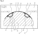
- Fig. 2 illustrates an exemplary embodiment for carrying out the method for manufacturing a fuselage shell from an outer skin 34 and closed omega stringers 23 in a device with a male molding tool 26.
- the male mold 26 has cavities 28 for positioning the closed omega stringers 23.
- a stiffening hollow profile cooling unit 30 for additional cooling of the closed omega stringers 23 is arranged under the cavities 28, for example comprising cooling lines with a cooling medium flowing through.
- the cavities 28 can also have insulation, for example in the form of a polytetrafluoroethylene or ceramic coating, which thermally isolate the cooled cavity 36 and the cooled cavities 28 from the rest of the heated male mold 26.
- the closed omega stringers 23 are positioned in the cavities 28, the surface of the cover layer 16 of the closed omega stringers 23 being approximately flush with the convex surface 27 of the male mold 26.
- the drawing is not true to scale and shows the closed omega stringers 23 in an enlarged view.
- An outer skin 34 is placed on the convex surface 27 of the male molding tool 26 in such a way that the surface of the cover layer 16 clings to the surface of the outer skin 34 in two-dimensional contact.
- the outer skin 34 can be consolidated or unconsolidated.
- the arrangement of closed omega stringers 23 and outer skin 34 is then placed in a gas-tight container 24 with a heating device, such as an autoclave 25, heated.
- a heating device such as an autoclave 25, heated.
- the autoclave 25 is under an overpressure p of, for example, approximately 2 to 40 bar, here approximately 10 bar, for example.
- the heating fluid 38 in the interior of the autoclave 25 is, for example, heated, pressurized air and has a temperature of, for example, 350 ° C. The temperature can therefore be about 10 ° C above the melting temperature of PEEK or above.
- the method is advantageously temperature-controlled so that only the outer skin 34 and the side of the stringer feet 21 facing the outer skin 34 or the cover layer 16 of the closed omega stringers 23 are heated above the melting temperature of PEEK.
- This principle is also used with other thermoplastics.
- a cooling fluid 40 flows through the elongated cavity 36 in the closed omega stringers 23, which cools the closed omega stringers 23 from the inside.
- the cooling fluid 40 has a temperature below the melting temperature of PEEK, preferably well below the melting temperature, for example below the long-term use temperature, below the heat deflection temperature or below the glass transition temperature of PEEK. Its temperature is well below 350 ° C (T ⁇ 350 ° C) and can in particular be at least 50 ° C and even more clearly below the melting temperature of PEEK.
- the cooling fluid 40 in the cavity 36 is under a pressure of, for example, approximately 10 bar and here also consists of pressurized air.
- the cooling fluid 40 is generated inside and / or outside the autoclave 25, for example from the heating fluid 38. Details on the production and introduction of the cooling fluid 40 are shown in FIG Fig. 3 illustrated.
- the closed omega stringers 23 can also be cooled from the outside by a cooling medium that flows through the stiffening hollow profile cooling unit 30 in the male mold 26.
- a gap 29 can form between the cavities 28 and the closed omega stringers 23.
- This gap 29 is optionally also subjected to the same overpressure as the interior of the autoclave 25. It can still be filled with cooling medium under overpressure. But it can also be put under vacuum.
- the selected fluid temperatures of heating fluid 38 and cooling fluid 38 aim to ensure that the outer skin 34 and, if possible, only the stringer foot side or the cover layer side, which is oriented in the direction of the outer skin 34, is brought to a temperature above the melting temperature by the heating fluid 38 heated by PEEK. PEEK softens or melts at the contact area between the outer skin 34 and the stringer foot side or the outer cover layer side.
- a mechanically stable, preferably cohesive connection is created between the outer skin 34 and the closed omega stringer 23.
- a non-consolidated outer skin 34 is consolidated under the selected pressure and temperature conditions.
- the shot omega stringers 23 and outer skin 34 are co-consolidated.
- the pressurized stringer is airtight and stable. There is no hose in the stringer
- the cooling fluid 40 in the cavity 36 of the closed omega stringer 23 and optionally the cooling medium in the stiffening hollow profile cooling unit 30 ensure that the closed omega stringers 23 at least in the area of the stringer cap 18 and the stringer webs 20 at one temperature be kept below the melting temperature of PEEK.
- the closed omega stringers 23 do not soften and remain dimensionally stable.
- the insertion of support elements, such as a hard or a semi-hard core, into the cavity 36 of the closed omega stringers 23 is not required to stabilize the closed omega stringers 14. A complex removal of such support elements is also not necessary.
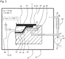
- FIG. 11 shows an enlarged detail of the device from FIG Fig. 2 . It illustrates methods A, B and C for cooling the closed omega stringers 23.
- a fluid line A, 44 is formed in the male mold 26, which connects the interior of the autoclave 25 with the cavity 36 in the closed omega stringers 23.
- the fluid line-A 44 is equipped with a fluid cooling unit A, 46, for example composed of cooling channels or cooling lines, which cools the inflowing heating fluid 38.
- the cooling fluid 40 formed is introduced into the cavity 36 of the closed omega stringers 23. It is under the same pressure of, for example, about 10 bar as the heating fluid 38, but has a lower temperature of T ⁇ 350.degree.
- heating fluid 38 flows out of the gas-tight autoclave 25 through a fluid line B, 48.
- the fluid line B, 48 has a fluid cooling unit B, 50 for cooling the heating fluid 38.
- the generated cooling fluid 40 is introduced through the fluid line B, 48 into the cavity 36 in the closed omega stringers 23. It is under the same pressure of about 10 bar as the heating fluid 38, but has a lower temperature of T ⁇ 350 ° C.
- the pressurized cooling fluid 40 is formed separately from the heating fluid 38. It is generated outside of the autoclave 25 in a separate pressure generation system and passed through the fluid line C, 52 into the cavity 36 in the closed omega stringers 23.
- the cooling fluid 40 is conveyed or formed by a pump 54 integrated in the fluid line C, 52.
- the pressure of the cooling fluid 40 corresponds approximately to the pressure of the heating fluid 38.
- Fig. 3 shows a combination of methods A, B and C. However, it is also possible to combine only methods A and B or A and C or B and C or only to carry out method A or method B or method C to achieve the To provide cooling fluid 40 for the cavity 36.
- the pressurized cooling fluid 40 is introduced into the cavity 36 through an opening at the end of the hollow stiffening profiles 10, 23 or one or more openings in a surface of the hollow stiffening profiles 10, 23, in particular in a web 20.
- the reinforcing hollow profile 10, 23 can be used for the introduction have a permanently mounted valve or a releasably attached valve.
- the stringer drainage holes can be used for this.
- Fig. 4 illustrates the implementation of the method according to the invention for producing a fuselage shell 12 from an outer skin 34 as an example for a flat component 32 and closed omega stringers 23 as an example for stiffening hollow profiles 10 in a device with a female molding tool 26.
- the outer skin 34 is laid on the concave surface of the female mold 42.
- the closed omega stringers 23 are positioned thereon.
- the components consist of a thermoplastic composite material made of a PEEK matrix with embedded carbon fibers.
- the female mold method is the same as the male mold method 26 in several respects. In this respect, the description of the procedure is referred to Fig. 2 referenced.
- the female molding tool 42 has no cavities 28 and no stiffening hollow profile cooling unit 30 that supports the cooling of the closed omega stringers 23. So that the closed omega stringers 23 remain dimensionally stable, the cavity 36 in the closed omega stringers 23 can be cooled to a greater extent. The cooling in the cavity 36 can result in the cover layer 16 melting more intensely in the edge area at the stringer feet 21 and forming a material bond with the stringer feet 21 because this area is in direct contact with the heating fluid 38 in the autoclave 25.
- the female molding tool 42 can have a heating device (not shown) which is preferably arranged in the vicinity of the concave surface of the molding tool 42 and which is provided for heating the outer skin 34 and closed omega stringers 23 placed on the concave surface.
- a heating device (not shown) which is preferably arranged in the vicinity of the concave surface of the molding tool 42 and which is provided for heating the outer skin 34 and closed omega stringers 23 placed on the concave surface.
- the heating power required for the integral connection can be used can be provided by the heating device in the molding tool 42 or combined with the heating power of a heating fluid 38 in the gas-tight container 24, 25.
- FIG. 11 shows an enlarged detail of the device with female molding tool 42 from FIG Fig. 4 , which illustrates methods B and C for cooling the closed omega stringers 23.
- the methods B and C shown here essentially correspond to the methods B and C, which are carried out with the male mold 26 (see FIG Fig. 3 ).
- the fluid lines B, 48 and C, 50 also run inside the autoclave 25 outside the molding tool 42.
- the cooling medium fed into the autoclave 25 from outside in processes B and C can be such as Fig. 5 shows further cooling within the autoclave 25 by a further fluid cooling unit C, 56.
- a further fluid cooling unit C, 56 can also be used in the in Fig. 3 device shown with male mold 26 are provided (not shown).
- Cooling methods B and C can be combined with one another. But they can also be carried out individually and independently of one another.
- the pressurized cooling fluid 40 is introduced into the cavity 36 through an opening at the end of the hollow stiffening profiles 10, 23 or one or more openings in a surface of the hollow stiffening profiles 10, 23, in particular in a web 20.
- the reinforcing hollow profile 10, 23 can have a permanently mounted valve or a releasably attached valve for introduction.
- the stringer drainage holes can be used for this.
- Fig. 6 illustrates the connection of a hose or a pipe with the pressurized cooling fluid 40 to a closed omega stringer 23, essentially for the method with female molding tool 42.
- the hose or pipe can be an end section of the fluid line B, 48 or the Act fluid line C 52.
- a closure cap 64 is inserted into the stringer 23.
- the closure cap 64 is installed prior to consolidation. It can be mounted on the stringer before the stringer is integrated. It is combined with an inlet valve 66.
- the stringer end can be provided with a stringer outlet made of CFRP, which remains in the stringer.
- the CFRP material can have a higher melting point than the CFRP material of the stringer 23.
- the same matrix system can be used for particularly strong cooling.
- This stringer outlet can be designed as a rivet for connecting the stringer to the outer skin. This means that other rivets for fastening the end of the stringer can be omitted.
- the outlet cap can be made larger and made of a stiffer material for this purpose.
- the invention consists in integrating a thermoplastic omega stringer on a thermoplastic skin (for a high temperature matrix, such as PEKK / PEEK) with an autoclave process without great effort in terms of the equipment of the tool and without the use of a sleeve or a hose, whereby nevertheless an internal pressure is maintained within the hollow omega profile.
- a thermoplastic omega stringer for a high temperature matrix, such as PEKK / PEEK
- the Omega profile should be produced in a closed form (cover layer over both feet) and not be completely heated (cooled).
- the end of the stringer enables the pressure in the autoclave to enter the hollow profile.
- the end of the profile can also be designed so that it acts like a redundant rivet element; a DT feature which prevents the stringer from completely detaching in the event of damage when the end portion of the stringer is subjected to a peak load.
- the pressure that enters the hollow profile does not have to come from an autoclave; it can also come from a separate pressure generation system. It could also be a cooling medium.
- thermoplastic outer skin is placed over the stringers. It can be consolidated or unconsolidated.
- the pressure in the stringer is the same as in the autoclave, but it is cooled to a temperature well below the melting point, it can remain stable and airtight.
- a press plate can be used on the skin to improve the quality of the outer loft surface.
- the stringer must remain stable (good cooling is required) as it is neither supported nor cooled by the tool; additional tool blocks are possible, but these would mean more effort; More cooling the stringer can help;
- the stringer foot cover layer can lead to a slight increase in weight, since this cover layer is normally not required.
- the effects of the weight can be mitigated, however, as the thicker stringer foot reduces the risk of kinking the skin under the stringer head and increases the kink resistance.
- the stringer tendency can possibly be increased slightly.
- the compressed air hose with the air flow used for cooling can also be connected directly to the stringer bar, with a fixed valve or a releasably attached valve. Such as. using the stringer drainage holes.
- Preferred features for the male mold For double-curved shells (or shells with a larger angle), demolding must be taken into account. Additional tool cores running along the stringer can be considered. The tool core can be arranged together with the stringer or in advance. These cores can enable demoulding with double-curved surfaces and a panel with a span or an arc of up to 180 ° bends. The cooling can be carried out in the tool core, or the tool can go through the tools. Even if the full length is covered, the tool can be the "cooling channel”.
Landscapes
- Engineering & Computer Science (AREA)
- Mechanical Engineering (AREA)
- Physics & Mathematics (AREA)
- Thermal Sciences (AREA)
- Aviation & Aerospace Engineering (AREA)
- Health & Medical Sciences (AREA)
- Oral & Maxillofacial Surgery (AREA)
- Casting Or Compression Moulding Of Plastics Or The Like (AREA)
- Moulds For Moulding Plastics Or The Like (AREA)
Abstract
Description
- Die vorliegende Erfindung betrifft ein Verfahren zum Herstellen eines versteiften flächigen Bauteils aus Polymermaterial zur Verwendung im Luftfahrzeugbau, das ein flächiges Bauteil aus Polymermaterial und daran integrierte Versteifungsprofile aus Polymermaterial aufweist. Sie betrifft weiterhin die so erhältlichen versteiften flächigen Bauteile und die damit hergestellten Luftfahrzeuge.
- Bauteile für Flugzeuge müssen zur Kraftstoffeinsparung ein möglichst geringes Gewicht aufweisen. Gleichzeitig müssen sie aus Sicherheitsgründen über eine hohe Festigkeit und Steifigkeit verfügen. Diese Ziele werden durch mechanisch stabile Materialien mit geringem spezifischem Gewicht und eine materialsparende Bauweise, wie die Halbschalenbauweise, erreicht.
- Es ist bekannt, wesentliche Segmente des Rumpfes eines Luftfahrzeugs, wie Außenhaut, Spanten und Versteifungsprofile, wie Omega-Stringer, aus dem Leichtmetall Aluminium und dessen Legierungen herzustellen.
- Eine weitere Gewichtseinsparung wird durch den Einsatz von duroplastischen Verbundwerkstoffen, wie kohlenstofffaserverstärkten Kunststoffen (CFK) (engl. "carbon fiber reinforced polymer" CFRP), beim Bau von Panels für den Luftfahrzeugrumpf ermöglicht. Derartige CFKs weisen eine Matrix aus duroplastischem Polymer mit darin eingebetteten Kohlenstofffasern auf.
- Bei der Fertigung von duroplastischen CFK-Panels wird zunächst auf einem männlichen Formwerkzeug die duroplastische Außenhaut hergestellt. Anschließend werden die duroplastischen Stringer auf einem weiblichen Formwerkzeug auf die Außenhaut integriert. Hierzu werden die Stringer aufgeklebt, wonach das gebildete CFK-Panel unter Hitze- und Druckeinwirkung gehärtet und konsolidiert wird.
- Für die Stringer-Integration werden konsolidierte Omega-Stringer an ihren Fußflächen mit Klebstoff versehen. In den Hohlraum der Omega-Stringer werden Folienschläuche eingelegt. Danach werden die Stringer auf die Außenhaut geklebt. In einem Autoklav findet die Co-Konsolidierung von Außenhaut und Stringern und damit die Stringer-Integration statt. Nach der Integration müssen die Folienschläuche rückstandslos aus dem Hohlraum zwischen Stringer und Außenhaut entfernt werden. Die Schlauchkerntechnik ermöglicht es, die Außenhaut auch in den Bereichen, in denen die Stringer die Außenhaut abdecken, zu konsolidieren.
- Neben den duroplastischen Verbundwerkstoffen finden zunehmend thermoplastische Verbundwerkstoffe Anwendung im Flugzeugbau. Dies hängt mit der Entwicklung von Hochtemperatur-thermoplastischen Materialien und Hochleistungskunststoffen zusammen. Sie verfügen über einen hohen Schmelzpunkt, eine hohe Beständigkeit gegen Hitze und Chemikalien und eine hohe Festigkeit und Steifigkeit. Zu diesen Hochtemperatur-thermoplastischen Materialien gehören die Polyaryletherketone (PAEK), wie Polyetheretherketon (PEEK) und Polyetherketonketon (PEKK). Sie können zu thermoplastischen Verbundwerkstoffen verarbeitet werden, die für den Flugzeugbau geeignet sind.
- Omega-Stringer umfassend thermoplastischen CFK können auf eine Außenhaut umfassend thermoplastischen CFK integriert werden. Die Stringer-Integration erfolgt unter Anwendung von Schweißtechniken und nicht durch Kleben. Hierfür werden Temperaturen von 350 bis 400 °C benötigt.
- Für die Integration von thermoplastischen Stringern an einer thermoplastischen Außenhaut sind im Stand der Technik verschiedene Techniken bekannt. Bei einem ersten Schweißverfahren werden die Außenhaut und die Versteifungsprofile lokal co-konsolidiert. Bei einem zweiten Schweißverfahren werden die thermoplastischen Polymere durch Induktionsschweißen zusammengefügt. Bei der Weiterentwicklung dieser Schweißtechniken wurde darauf fokussiert, das lokale Co-Konsolidieren durch ein globales Co-Konsolidieren zu ersetzen. Hierfür wurde die Schlauchkerntechnik weiterentwickelt, insbesondere wurde an der technischen Reife des Folienschlauchs gearbeitet wurde.
- Zusammenfassend gibt es derzeit die folgenden Konzepte für die Integration von Omega-Stringers aus thermoplastischem Verbundwerkstoff: (1) Das Einbringen eines steifen Kerns oder eines halbsteifen Kerns, wie aus einem Silikon; (2) Das Verschweißen unter lokalem Co-Konsolidieren des Stringer-Fußes; (3) Das Einbringen eines Schlauchs in den Omega-Stringer. Das Verfahren ist aufwändig.
- Es ist Aufgabe der vorliegenden Erfindung, ein verbessertes Verfahren für die Herstellung von thermoplastischen versteiften flächigen Bauteilen bereitzustellen.
- Zum Lösen dieser Aufgabe schlägt die Erfindung eine Verfahren nach Anspruch 1 vor.
- Vorteilhafte Ausgestaltungen der Erfindung sind Gegenstand der Unteransprüche.
- Gemäß einem ersten Aspekt schafft die Erfindung ein Verfahren zum Herstellen eines versteiften flächigen Bauteils auf Polymerbasis insbesondere zur Verwendung im Luftfahrzeugbau umfassend ein flächiges Bauteil auf Polymerbasis und daran befestigte Versteifungsprofile auf Polymerbasis. Dieses Verfahren umfasst mindestens folgende Schritte:
- a) Bereitstellen von Versteifungshohlprofilen, die thermoplastischen Verbundwerkstoff umfassen, eines flächigen Bauteils, das thermoplastischen Verbundwerkstoff umfasst, eines Formwerkzeugs und eines gasdichten Behälters;
- b) Anordnen der Versteifungshohlprofile und des flächigen Bauteils auf der Oberfläche des Formwerkzeugs unter flächigem Inkontaktbringen einer Versteifungshohlprofilwand der Versteifungshohlprofile mit dem flächigen Bauteil;
- c) Erhitzen der in Schritt b) erhaltenen Anordnung in dem gasdichten Behälter mit einem unter Überdruck stehenden Heizfluid, dessen Temperatur oberhalb der Schmelztemperatur des thermoplastischen Verbundwerkstoffs liegt, und/oder in dem mit einem Überdruck beaufschlagten gasdichten Behälter mit einer in dem Formwerkzeug ausgebildeten Heizeinrichtung, die mindestens die Formwerkzeugoberfläche auf eine Temperatur oberhalb der Schmelztemperatur des thermoplastischen Verbundwerkstoffs erhitzt, unter Kühlen der Versteifungshohlprofile mit einem durch den Hohlraum der Versteifungshohlprofile strömenden, unter Überdruck stehenden Kühlfluid mit einer Temperatur unterhalb der Schmelztemperatur des thermoplastischen Verbundwerkstoffs;
- d) Abkühlen der Anordnung auf Umgebungstemperatur unter stoffschlüssigem Verbinden der Versteifungshohlprofilwände mit dem flächigen Bauteil.
- Die gemäß Schritt a) bereitgestellten Versteifungshohlprofile und das flächige Bauteil können aus thermoplastischem Verbundwerkstoff bestehen. Sie können aber auch thermoplastischen Verbundwerkstoff in Kombination mit einem oder mehreren anderen Materialien enthalten.
- Es ist bevorzugt, dass die Versteifungshohlprofile geschlossene Omega-Stringer sind, die einen Omega-Stringer mit Stringer-Kappe, Stringer-Stegen und Stringer-Füßen und eine mit den Stringer-Füßen verbundene, insbesondere stoffschlüssig verbundene Abdecklage oder eine die Stringer-Füße bildende Abdecklage umfassen, wobei die Abdecklage oder die Abdecklage und die Stringer-Füße die Versteifungshohlprofilwand bilden, die für den flächigen Kontakt mit dem flächigen Bauteil vorgesehen ist. Vorzugsweise werden die Oberflächen der Stringer-Füße vollständig von der Abdecklage abgedeckt.
- Es ist bevorzugt, dass Schritt a) das Bereitstellen von Versteifungshohlprofilen und/oder eines flächigen Bauteils umfasst, die einen thermoplastischen Verbundwerkstoff enthalten, der umfasst:
- ein oder mehrere thermoplastische Polymere als Matrixmaterial, die unter Hochtemperatur-thermoplastischen Polymeren, Hochleistungskunststoffen, teilkristallinen Hochleistungskunststoffen, Polyaryletherketonen (PAEK), wie Polyetherketonketon (PEKK), Polyetherketon (PEK), Polyetheretherketonen (PEEK), Polyetheretheretherketon (PEEEK), Polyetheretherketonketon (PEEKK) und Polyetherketon-etherketonketon (PEKEKK), insbesondere unter PEEK und PEKK, ausgewählt werden, und
- ein Verstärkungsmaterial, vorzugsweise synthetische Fasern, besonders bevorzugt Kohlenstofffasern, das/die in das Matrixmaterial eingebettet ist/sind.
- Die Schmelztemperatur und die Glasübergangstemperatur von Polymeren, wie den Polyaryletherketonen, variieren in Abhängigkeit von der Kettenlänge, dem Anteil und der Abfolge der Ethergruppen und Ketogruppen und den Verfahrensbedingungen, unter denen das betreffende PAEK hergestellt wurde. Die Glasübergangstemperatur (Tg) vieler Polyaryletherketone liegt im Bereich von etwa 140 °C bis etwa 170 °C , ihre Schmelztemperatur (Tf) im Bereich von etwa 340 °C bis 380 °C, ihre Wärmeformbeständigkeit liegt in einem Bereich von etwa 150 °C bis etwa 180 °C. Als Dauergebrauchstemperatur der Polyaryletherketone wird in der Literatur beispielhaft 250 °C angegeben.
- Es ist bevorzugt, dass Schritt a) das Bereitstellen des flächigen Bauteils im nicht konsolidierten Zustand und der Versteifungshohlprofile im konsolidierten Zustand umfasst.
- Es ist bevorzugt, dass Schritt a) das Bereitstellen eines Formwerkzeugs, insbesondere männlichen Formwerkzeugs mit Kavitäten zum Aufnehmen der Versteifungshohlprofile umfasst.
- Es ist bevorzugt, dass Schritt a) das Bereitstellen eines Formwerkzeugs, insbesondere männlichen Formwerkzeugs mit Kavitäten zum Aufnehmen der Versteifungshohlprofile und mit einer Versteifungshohlprofil-Kühleinheit, die benachbart zu den Kavitäten ausgebildet ist, umfasst.
- Es ist bevorzugt, dass Schritt a) das Bereitstellen eines männlichen Formwerkzeugs mit einem konvex geformten Oberflächenbereich zum Ablegen des flächigen Bauteils umfasst.
- Es ist bevorzugt, dass Schritt a) das Bereitstellen eines weiblichen Formwerkzeugs mit einem konkav geformten Oberflächenbereich zum Ablegen des flächigen Bauteils umfasst.
- Es ist bevorzugt, dass Schritt a) das Bereitstellen eines Formwerkzeugs, insbesondere weiblichen Formwerkzeugs, mit einer Heizeinrichtung zum Erhitzen der auf dem Formwerkzeug abgelegten Anordnung aus flächigem Bauteil und Versteifungshohlprofile umfasst.
- Es ist bevorzugt, dass Schritt a) das Bereitstellen eines Autoklavs oder eines Pressklavs als gasdichter Behälter umfasst.
- Es ist bevorzugt, dass Schritt a) das Bereitstellen von Versteifungshohlprofilen umfasst, deren Endabschnitte so ausgebildet sind, dass sie die Funktion von Nieten zur Befestigung der Versteifungshohlprofile an dem flächigen Bauteil haben.
- Es ist bevorzugt, dass Schritt b) das Anordnen der Versteifungshohlprofile in den Kavitäten des Formwerkzeugs und das Ablegen des flächigen Bauteils auf der Oberfläche des Formwerkzeugs umfasst
- Es ist bevorzugt, dass Schritt b) das Anordnen des flächigen Bauteils auf der Oberfläche des Formwerkzeugs und das Positionieren der Versteifungshohlprofile auf der Oberfläche des flächigen Bauteils umfasst
- Es ist bevorzugt, dass Schritt b) das Inkontaktbringen der Oberfläche der Abdecklage mit der Oberfläche des flächigen Bauteils umfasst.
- Es ist bevorzugt, dass Schritt c) das Verwenden von Luft oder eines inerten Gases als Heizfluid und/oder als Kühlfluid umfasst.
- Es ist bevorzugt, dass Schritt c) das Verwenden eines Heizfluids und/oder eines beheizten Formwerkzeugs mit einer Temperatur, die mindestens 10 °C über der Schmelztemperatur des thermoplastischen Verbundwerkstoffs liegt, und/oder eines Kühlfluids mit einer Temperatur, die mindestens 50 °C unter der Schmelztemperatur des thermoplastischen Verbundwerkstoffs liegt, umfasst.
- Es ist bevorzugt, dass Schritt c) das Verwenden eines Heizfluids und/oder eines beheizten Formwerkzeugs mit einer Temperatur von etwa 5 °C bis etwa 120 °C, vorzugsweise etwa 10 °C bis etwa 100 °C, noch bevorzugter etwa 10 °C bis etwa 80 °C, besonders bevorzugt etwa 10 °C bis etwa 60 °C über der Schmelztemperatur des thermoplastischen Verbundwerkstoffs und eines Kühlfluids (40) mit einer Temperatur von etwa 50 °C bis etwa 250 °C, vorzugsweise etwa 60 °C bis etwa 180 °C, bevorzugter etwa 70 °C bis etwa 160 °C, besonders bevorzugt etwa 90 °C bis etwa 140 °C unter der Schmelztemperatur des thermoplastischen Verbundwerkstoffs umfasst.
- Das Kühlfluid kann beispielsweise auch eine Temperatur etwa bei Raumtemperatur oder Umgebungstemperatur aufweisen, wenn durch die sonstigen Verfahrensbedingungen, wie Aggregatzustand von Kühlfluid und Heizfluid und Temperatur des Heizfluids, gewährleistet ist, dass im Kontaktbereich von Versteifungshohlprofilwand der Versteifungshohlprofile und flächigem Bauteil eine so hohe Temperatur herrscht, dass es durch Schmelzen oder Erweichen und anschließendes Abkühlen zur stoffschlüssigen Verbindung dieser Bauteile kommt.
- Der Fachmann wählt die Temperatur des Heizfluids so knapp über der Schmelztemperatur des thermoplastischen Verbundwerkstoffs und die Temperatur des Kühlfluids so deutlich unter der Schmelztemperatur des thermoplastischen Verbundwerkstoffs, dass das thermoplastische Polymer im thermoplastischen Verbundwerkstoff an der Kontaktfläche zwischen den Versteifungshohlprofilen und dem flächigen Bauteil schmilzt und/oder plastifiziert und/oder erweicht und in den sonstigen Abschnitten der Versteifungshohlprofile nicht schmilzt und/oder nicht erweicht und/oder elastisch bleibt und/oder formstabil bleibt.
- Bei Verwendung von PEEK kann das Heizfluid beispielsweise eine Temperatur von etwa 350 °C bis etwa 400 °C und/oder das Kühlfluid eine Temperatur von etwa 200 °C bis etwa 250 °C aufweisen. Die Temperatur des Kühlfluids kann vorzugsweise auch bei ca. 150 °C und damit im Bereich der Wärmeformbeständigkeit von PEEK liegen. Besonders bevorzugt kann die Temperatur des Kühlfluids bei ca. 140 °C und damit im Bereich der Glasübergangstemperatur von PEEK liegen.
- Die Temperatur des Kühlfluids kann bei PEEK wie bei den sonstigen Hochleistungskunststoffen vorzugsweise bei einer Temperatur liegen, die so niedrig gewählt ist, dass die Temperatur der zu kühlenden Bauteile der Versteifungshohlprofile unter der Wärmeformbeständigkeitstemperatur und insbesondere der Glasübergangstemperatur bleibt.
- Es ist bevorzugt, dass Schritt c) das Verwenden eines Heizfluids und/oder eines beheizten Formwerkzeugs in Kombination mit einem Kühlfluid umfasst, deren Temperatur so gewählt wird, dass das flächige Bauteil und die Versteifungshohlprofilwand, insbesondere nur die an das flächige Bauteil angrenzende Seite der Versteifungshohlprofilwand, über die Schmelztemperatur des thermoplastischen Verbundwerkstoffs erhitzt werden und die sonstigen Abschnitte der Versteifungshohlprofile bei einer Temperatur unter der Schmelztemperatur des thermoplastischen Verbundwerkstoffs bleiben.
- Es ist bevorzugt, dass Schritt c) das Verwenden eines Heizfluids und/oder eines beheizten Formwerkzeugs in Kombination mit einem Kühlfluid umfasst, deren Temperatur so gewählt wird, dass die Versteifungshohlprofilwand und das flächige Bauteil nach Abkühlen stoffschlüssig miteinander verbunden werden und/oder die sonstigen Abschnitte der Versteifungshohlprofile formstabil bleiben und/oder die Versteifungshohlprofile luftdicht bleiben.
- Es ist bevorzugt, dass Schritt c) das Erzeugen eines Drucks pA im Bereich von etwa 2 bis 40 bar, vorzugsweise etwa 5 bis 20 bar, insbesondere etwa 8 bis 12 bar, durch Druckerzeugen im gasdichten Behälter und/oder durch ein externes Druckerzeugungssystem umfasst.
- Es ist bevorzugt, dass Schritt c) das Erzeugen eines Überdrucks in den Versteifungshohlprofilen umfasst, bei dem die Versteifungshohlprofilwand des Versteifungshohlprofils oder die Abdecklage der geschlossenen Omega-Stringer genau der angestrebten Oberflächenform des Luftfahrzeugbauteils folgt.
- Es ist bevorzugt, dass Schritt c) das Erzeugen eines Überdrucks in dem gegebenenfalls zwischen den Kavitäten und den in die Kavitäten abgelegten Versteifungshohlprofilen vorhandenen Spalt umfasst.
- Es ist bevorzugt, dass das Kühlen der Versteifungshohlprofile in Schritt c) das Einleiten von Heizfluid aus dem gasdichten Behälter in eine im männlichen Formwerkzeug ausgebildete Fluidleitung-A, die mit einer Fluidkühleinheit-A zum Kühlen des Heizfluids ausgestattet ist, und Einleiten des gebildeten Kühlfluids in den Hohlraum in den Versteifungshohlprofilen umfasst (Verfahren A in
Fig. 3 )). - Es ist bevorzugt, dass das Kühlen der Versteifungshohlprofile in Schritt c) das Herausleiten von Heizfluid aus dem gasdichten Behälter in eine externe Fluidleitung B, die mit einer Fluidkühleinheit B zum Kühlen des Heizfluids ausgestattet ist, und Einleiten des gebildeten Kühlfluids in den gasdichten Behälter und nachfolgend den Hohlraum in den Versteifungshohlprofilen umfasst (Verfahren B in
Fig. 3 undFig. 5 )). - Es ist bevorzugt, dass das Kühlen der Versteifungshohlprofile in Schritt c) das Erzeugen von unter Überdruck stehendem Kühlfluid außerhalb des gasdichten Behälters in einem separaten Druckerzeugungssystem und/oder mit einer Pumpe und Einleiten des Kühlfluids durch eine Fluidleitung-C in den gasdichten Behälter und nachfolgend den Hohlraum in den Versteifungshohlprofilen umfasst (Verfahren C in
Fig. 3 Fig. 5 )). - Es ist bevorzugt, dass Schritt c) das Verwenden eines gekühlten oder isolierten Schlauches oder Rohrs für das Einleiten des unter Überdruck stehenden Kühlfluids in den Hohlraum umfasst.
- Es ist bevorzugt, dass Schritt c) das Einleiten des unter Überdruck stehenden Kühlfluids in den Hohlraum durch eine endständige Öffnung der Versteifungshohlprofile und/oder durch eine oder mehrere Öffnungen in einem Steg der geschlossenen Omega-Stringer, insbesondere durch ein Einlassventil, umfasst.
- Es ist bevorzugt, dass Schritt c) das Kühlen des von außerhalb des gasdichten Behälters zugeführten Kühlfluids mit einer Fluidkühleinheit C innerhalb des gasdichten Behälters umfasst.
- Es ist bevorzugt, dass Schritt c) das Einleiten von unter Überdruck stehendem Kühlfluid in dem gegebenenfalls zwischen den Kavitäten und den in die Kavitäten abgelegten Versteifungshohlprofilen vorhandenen Spalt umfasst.
- Es ist bevorzugt, dass Schritt d) das Abkühlen der Anordnung durch Abkühlenlassen an der Umgebungsluft umfasst.
- Es ist bevorzugt, dass Schritt d) das Abkühlen der Anordnung durch aktives Kühlen mit einem Kühlmedium umfasst.
- Es ist bevorzugt, dass Schritt d) das Abkühlen durch aktives Kühlen und/oder Abkühlenlassen der Anordnung unter Wahrung des in dem gasdichten Behälter herrschenden Fügedrucks, bis die Temperatur der Anordnung unter der für den Stoffschluss erforderlichen Temperatur, besonders unter der Dauergebrauchstemperatur, vorzugsweise unter der Wärmeformbeständigkeitstemperatur, besonders bevorzugt unter der Glasübergangstemperatur des thermoplastischen Verbundwerkstoffs liegt, umfasst.
- Es ist bevorzugt, dass die Versteifungshohlprofile in den Kavitäten des Formwerkzeugs durch ein Kühlmedium gekühlt werden, das durch die in dem Formwerkzeug angrenzend an die Kavitäten ausgebildete Versteifungshohlprofil-Kühleinheit strömt.
- Es ist bevorzugt, dass auf der Anordnung aus Versteifungshohlprofilen und flächigem Bauteil eine Vakuumfolie abgelegt wird und anschließend ein Vakuum zwischen der Vakuumfolie und der Oberfläche des Formwerkzeugs und/oder der Oberfläche des flächigen Bauteils und/oder der Oberfläche der Versteifungshohlprofile erzeugt wird.
- Es ist bevorzugt, dass auf der Anordnung aus Versteifungshohlprofilen und flächigem Bauteil eine Vakuumfolie abgelegt wird und anschließend ein Vakuum zwischen der Vakuumfolie und der Oberfläche des Formwerkzeugs und/oder der Oberfläche des flächigen Bauteils und/oder der Oberfläche der Versteifungshohlprofile erzeugt wird.
- Gemäß einem zweiten Aspekt schafft die Erfindung einen geschlossenen Omega-Stringer bereit, der insbesondere zur Verwendung für die Herstellung eines versteiften flächigen Bauteils vorgesehen ist. Erweist einen Omega-Stringer mit Stringer-Kappe, Stringer-Stegen und Stringer-Füßen und eine mit den Stringer-Füßen stoffschlüssig verbundene Abdecklage auf, wobei der Omega-Stringer und die Abdecklage einen thermoplastischen Verbundwerkstoff enthalten und wobei die Abdecklage für den flächigen Kontakt mit dem flächigen Bauteil vorgesehen ist.
- Der geschlossene Omega-Stringer kann durch Verschweißen der Füße des offenen Omega-Stringers mit der Abdecklage oder einteilig durch Pultrusion hergestellt werden.
- Gemäß einem dritten Aspekt schafft die Erfindung ein versteiftes flächiges Bauteil, wie einer Flugzeugschale, einer Rumpfschale oder eines Panels, das nach einem weiter oben beschriebenen Verfahren erhältlich ist und/oder das die weiter oben beschriebenen geschlossenen Omega-Stringer umfasst, die an ihrer Abdecklage, insbesondere an der Oberfläche ihrer Abdecklage, stoffschlüssig mit einem flächigen Bauteil verbunden sind, das einen thermoplastischen Verbundwerkstoff umfasst.
- Gemäß einem vierten Aspekt schafft die Erfindung ein Luftfahrzeug, das die weiter oben beschriebenen geschlossenen Omega-Stringer oder ein oder mehrere der oben beschriebenen versteiften flächigen Bauteile enthält.
- Gemäß einem fünften Aspekt schafft die Erfindung eine Vorrichtung zum Durchführen des weiter oben beschriebenen Verfahrens oder zum Herstellen des weiter oben beschriebenen versteiften flächigen Bauteils, die umfasst:
- a) ein Formwerkzeug, insbesondere männliches Formwerkzeug oder weibliches Formwerkzeug mit einer Oberfläche zum Anordnen von Versteifungshohlprofilen und eines flächigen Bauteils, die einen thermoplastischen Verbundwerkstoff enthalten;
- b) ein Formwerkzeug, das mit einer Heizvorrichtung zum Beheizen der Anordnung aus Versteifungshohlprofilen und flächigem Bauteil ausgestattet ist;
- c) einen gasdichten Behälter zum Erhitzen der Anordnung aus Versteifungshohlprofilen und flächigem Bauteil unter Überdruck;
- d) Kühleinrichtungen zum Kühlen der Versteifungshohlprofile, die umfassen:
- eine Leitung innerhalb des männlichen Formwerkzeugs, die den Innenraum des gasdichten Behälters mit dem Hohlraum in den Versteifungshohlprofilen verbindet, die mit einem Fluidkühlsystem, insbesondere Fluidkühlleitungen, ausgestattet ist, zum Einleiten und Kühlen von Heizfluid und Weiterleiten des gebildeten Kühlfluids in den Hohlraum der Versteifungshohlprofile; und/oder
- eine Leitung, die aus dem gasdichten Behälter herausführt, die mit einem Fluidkühlsystem, insbesondere Fluidkühlkanäle, ausgestattet ist, zum Herausleiten und Kühlen von Heizfluid, und eine Rückleitung in den gasdichten Behälter zum Einleiten des gebildeten Kühlfluids in den Hohlraum in den Versteifungshohlprofilen; und/oder
- eine externe Druckerzeugungsvorrichtung zum Bereitstellen von unter Überdruck stehendem Kühlfluid außerhalb des gasdichten Behälters und Leitungen zum Einleiten des erzeugten Kühlfluids in den Hohlraum der Versteifungshohlprofil
- eine Fluidkühleinheit C innerhalb des gasdichten Behälters zum Kühlen des durch die Fluidleitung B bzw. die Fluidleitung C zugeführten Kühlfluids (40).
- Es ist bevorzugt, dass das Formwerkzeug Kavitäten zur Aufnahme der Versteifungshohlprofile aufweist, wobei gegebenenfalls angrenzend an die Kavitäten eine Kühleinheit zum Kühlen der Versteifungshohlprofile mit einem Kühlfluid ausgebildet ist.
- Im Folgenden werden Ausführungsbeispiele anhand der beigefügten Zeichnungen näher erläutert. Darin zeigt:
- Fig. 1
- schematisch die Herstellung eines Versteifungshohlprofils in einer Querschnittsdarstellung;
- Fig. 2
- eine Vorrichtung zur Durchführung des erfindungsgemäßen Verfahrens unter Verwendung eines männlichen Formwerkzeugs;
- Fig. 3
- eine Ausschnittvergrößerung der Vorrichtung gemäß
Fig. 2 zur Veranschaulichung der Kühlung der Versteifungshohlprofile; - Fig. 4
- eine Vorrichtung zur Durchführung des erfindungsgemäßen Verfahrens unter Verwendung eines weiblichen Formwerkzeugs;
- Fig. 5
- eine Ausschnittvergrößerung der Vorrichtung gemäß
Fig. 4 zur Veranschaulichung der Kühlung der Versteifungshohlprofile; - Fig. 6
- die Anbindung einer Leitung mit unter Druck stehendem Kühlfluid an ein Versteifungshohlprofil.
- Im Folgenden wird die Herstellung eines versteiften flächigen Bauteils 12 aus einem flächigen Bauteil 32 und Versteifungshohlprofilen 10 beschrieben. Beispielhaft betrifft das dargestellte Verfahren die Herstellung einer Rumpfschale 12 aus einer Außenhaut 34 und geschlossenen Omega-Stringern 23. Alle Bauteile bestehen beispielsweise aus einem thermoplastischen Verbundwerkstoff aus Polyetheretherketon (PEEK) mit einer Schmelztemperatur etwa 340 °C und Kohlenstofffasern.
-
Fig. 1 zeigt schematisch in einer Querschnittsdarstellung den Aufbau und die Herstellung eines geschlossenen Omega-Stringers 23. Der geschlossene Omega-Stringer 23 umfasst einen Omega-Stringer 14, der eine Kappe 18, zwei Stege 20 und zwei Füße 21 aufweist, und eine den Omega-Stringer 14 an seinen Füßen 21 verschließende Abdecklage 16. - Die Abdecklage 16 und die beiden Füße 21 des Omega-Stringers 14 werden miteinander in Kontakt gebracht und beispielsweise durch Erhitzen mindestens der Kontaktflächen zwischen den Füßen 21 und Abdecklage 16 stoffschlüssig miteinander verbunden. Es wird ein geschlossener Omega-Stringer 23 erhalten, der bei verschlossenen Stringer-Enden luftdicht ist und unter Überdruck gesetzt werden kann.
- Die Abdecklage 16 bildet die Versteifungshohlprofilwand 22 des geschlossenen Omega-Stringers 23, die zur Herstellung der Rumpfschale mit der Außenhaut 34 in flächigen Kontakt gebracht und dann stoffschlüssig verbunden wird.
-
Fig. 2 veranschaulicht ein Ausführungsbeispiel für die Durchführung des Verfahrens zum Herstellen einer Rumpfschale aus einer Außenhaut 34 und geschlossene Omega-Stringers 23 in einer Vorrichtung mit männlichem Formwerkzeug 26. - Das männlichen Formwerkzeug 26 weist Kavitäten 28 zum Positionieren der geschlossenen Omega-Stringer 23 auf.
- Unter den Kavitäten 28 ist hier beispielhaft eine Versteifungshohlprofil-Kühleinheit 30 zum zusätzlichen Kühlen der geschlossenen Omega-Stringer 23 angeordnet, die beispielsweise Kühlleitungen mit einem hindurchströmenden Kühlmedium umfasst.
- Die Kavitäten 28 können aber auch eine Isolierung, beispielsweise in Form einer Polytetrafluorethylen- oder Keramikbeschichtung, aufweisen, die den gekühlten Hohlraum 36 und die gekühlten Kavitäten 28 vom übrigen erhitzten männlichen Formwerkzeug 26 thermisch isolieren.
- Die geschlossenen Omega-Stringer 23 werden in den Kavitäten 28 positioniert, wobei die Oberfläche der Abdecklage 16 der geschlossenen Omega-Stringer 23 in etwa bündig mit der konvexen Oberfläche 27 des männlichen Formwerkzeugs 26 abschließt. Die Zeichnung ist nicht maßstabsgetreu und zeigt die geschlossenen Omega-Stringer 23 in vergrößerter Darstellung. Auf der konvexen Oberfläche 27 des männlichen Formwerkzeugs 26 wird eine Außenhaut 34 so abgelegt, dass sich die Oberfläche der Abdecklage 16 an die Oberfläche der Außenhaut 34 im flächigen Kontakt anschmiegt. Die Außenhaut 34 kann konsolidiert oder nicht konsolidiert sein.
- Anschließend wird die Anordnung aus geschlossenen Omega-Stringern 23 und Außenhaut 34 in einem gasdichten Behälter 24 mit Heizvorrichtung, wie einem Autoklav 25, erhitzt. Der Autoklav 25 steht unter einem Überdruck p von beispielsweise etwa 2 bis 40 bar, hier beispielhaft etwa 10 bar. Das Heizfluid 38 im Innenraum des Autoklavs 25 ist beispielsweise erhitzte, unter Überdruck stehende Luft und hat eine Temperatur von beispielsweise ≥ 350 °C. Die Temperatur kann also etwa 10 °C über der Schmelztemperatur von PEEK oder darüber liegen.
- Vorteilhaft wird das Verfahren so temperaturgesteuert, dass nur die Außenhaut 34 und die der Außenhaut 34 zugewandte Seite der Stringer-Füße 21 oder der Abdecklage 16 der geschlossenen Omega-Stringer 23 über die Schmelztemperatur von PEEK erhitzt werden. Dieses Prinzip findet auch bei anderen Thermoplasten Anwendung. Um die übrigen Abschnitte der geschlossenen Omega-Stringer 23 vor einem die Stringer-Form destabilisierenden Schmelzen zu schützen, strömt ein Kühlfluid 40 durch den langgestreckten Hohlraum 36 in den geschlossenen Omega-Stringern 23, das die geschlossenen Omega-Stringer 23 von innen kühlt.
- Das Kühlfluid 40 hat eine Temperatur unter der Schmelztemperatur von PEEK, vorzugsweise deutlich unter der Schmelztemperatur, beispielsweise unter der Dauergebrauchstemperatur, unter der Wärmeformbeständigkeitstemperatur oder unter der Glasübergangstemperatur von PEEK. Seine Temperatur liegt deutlich unter 350 °C (T << 350 °C) und kann insbesondere mindestens 50 °C und noch deutlicher unter der Schmelztemperatur von PEEK liegen. Das Kühlfluid 40 in dem Hohlraum 36 steht unter einem Druck von beispielsweise etwa 10 bar und besteht hier ebenfalls aus unter Druck stehender Luft. Das Kühlfluid 40 wird innerhalb und/oder außerhalb des Autoklavs 25 erzeugt, beispielsweise aus dem Heizfluid 38. Einzelheiten zu Herstellung und Einleitung des Kühlfluids 40 werden in
Fig. 3 veranschaulicht. - Als weiterer Schutz vor einem Schmelzen bestimmter Bauteil-Abschnitte können die geschlossenen Omega-Stringer 23 außerdem von außen durch ein Kühlmedium gekühlt werden, das durch die Versteifungshohlprofil-Kühleinheit 30 in dem männlichen Formwerkzeug 26 strömt.
- Zwischen den Kavitäten 28 und den geschlossenen Omega-Stringern 23 kann es zur Ausbildung eines Spalts 29 kommen. Dieser Spalt 29 wird gegebenenfalls ebenfalls mit dem gleichen Überdruck wie der Innenraum des Autoklavs 25 beaufschlagt. Er kann weiterhin mit unter Überdruck stehendem Kühlmedium gefüllt werden. Er kann aber auch unter Vakuum gesetzt werden.
- Zusammenfassend zielen die gewählten Fluidtemperaturen von Heizfluid 38 und Kühlfluid 38 darauf ab, dass die Außenhaut 34 und möglichst nur die Stringer-Fuß-Seite oder die Abdecklagenseite, die in Richtung der Außenhaut 34 orientiert ist, durch das Heizfluid 38 auf eine Temperatur über der Schmelztemperatur von PEEK erhitzt werden. PEEK erweicht oder schmilzt an der Kontaktfläche zwischen Außenhaut 34 und Stringer-Fuß-Seite oder äußerer Abdecklagenseite. Beim Abkühlen entsteht eine mechanisch stabile, vorzugsweise stoffschlüssige Verbindung zwischen der Außenhaut 34 und dem geschlossenen Omega-Stringer 23. Eine nicht konsolidierte Außenhaut 34 wird unter den gewählten Druck- und Temperaturbedingungen konsolidiert. Die geschossenen Omega-Stringer 23 und Außenhaut 34 werden co-konsolidiert. Der unter Druck stehende Stringer ist luftdicht und stabil. In dem Stringer befindet sich kein Schlauch
- Das Kühlfluid 40 in dem Hohlraum 36 des geschlossenen Omega-Stringers 23 und gegebenenfalls das Kühlmedium in der Versteifungshohlprofil-Kühleinheit 30 sorgen dafür, dass die geschlossenen Omega-Stringer 23 mindestens im Bereich der Stringer-Kappe 18 und der Stringer-Stege 20 bei einer Temperatur unter der Schmelztemperatur von PEEK gehalten werden. Die geschlossenen Omega-Stringer 23 erweichen nicht und bleiben formstabil. Das Einlegen von Stützelementen, wie eines harten oder eines semiharten Kerns, in den Hohlraum 36 der geschlossenen Omega-Stringer 23 ist zur Stabilisierung der geschlossenen Omega-Stringer 14 nicht erforderlich. Ein aufwändiges Entfernen derartiger Stützelemente entfällt ebenfalls.
-
Fig. 3 zeigt eine Ausschnittvergrößerung der Vorrichtung vonFig. 2 . Sie veranschaulicht Verfahren A, B und C zum Kühlen der geschlossenen Omega-Stringer 23. - Für das Verfahren A ist in dem männlichen Formwerkzeug 26 eine Fluidleitung A, 44 ausgebildet, die den Innenraum des Autoklavs 25 mit dem Hohlraum 36 in den geschlossenen Omega-Stringern 23 verbindet. Die Fluidleitung-A 44 ist mit einer Fluidkühleinheit A, 46, beispielsweise aus Kühlkanälen oder Kühlleitungen, ausgestattet, die das einströmende Heizfluid 38 abkühlt. Das gebildete Kühlfluid 40 wird in den Hohlraum 36 der geschlossenen Omega-Stringer 23 eingeleitet. Es steht unter dem gleichen Druck von beispielsweise etwa 10 bar wie das Heizfluid 38, weist aber eine niedrigere Temperatur von T << 350 °C auf.
- Beim Verfahren B strömt Heizfluid 38 durch eine Fluidleitung B, 48 aus dem gasdichten Autoklav 25 heraus. Außerhalb des Autoklavs 25 weist die Fluidleitung B, 48 eine Fluidkühleinheit B, 50 zum Kühlen des Heizfluids 38 auf. Das erzeugte Kühlfluid 40 wird durch die Fluidleitung B, 48 in den Hohlraum 36 in den geschlossenen Omega-Stringern 23 eingeleitet. Es steht unter dem gleichen Druck von etwa 10 bar wie das Heizfluid 38, weist aber eine niedrigere Temperatur von T << 350 °C auf.
- Beim Verfahren C wird das unter Druck stehende Kühlfluid 40 separat vom Heizfluid 38 gebildet. Es wird außerhalb des Autoklavs 25 in einem separaten Druckerzeugungssystem erzeugt und durch die Fluidleitung C, 52 in den Hohlraum 36 in den geschlossenen Omega-Stringern 23 geleitet. Das Kühlfluid 40 wird durch eine in der Fluidleitung C, 52 integrierte Pumpe 54 gefördert oder gebildet. Der Druck des Kühlfluids 40 entspricht in etwa dem Druck des Heizfluids 38.
-
Fig. 3 zeigt eine Kombination der Verfahren A, B und C. Es ist aber auch möglich, nur die Verfahren A und B oder A und C oder B und C zu kombinieren oder ausschließlich das Verfahren A oder das Verfahren B oder das Verfahren C durchzuführen, um das Kühlfluid 40 für den Hohlraum 36 bereitzustellen. - Das unter Überdruck stehende Kühlfluid 40 wird durch eine Öffnung am Ende der Versteifungshohlprofile 10, 23 oder eine oder mehrere Öffnungen in einer Oberfläche der Versteifungshohlprofile 10, 23, insbesondere in einem Steg 20, in den Hohlraum 36 eingeleitet. Das Versteifungshohlprofil 10, 23 kann für das Einleiten ein fest montiertes Ventil oder ein lösbar befestigtes Ventil aufweisen. Hierfür können zum Beispiel die Stringer-Abflusslöcher verwendet werden. Nach Durchströmen des Hohlraums 36 wird das Kühlfluid 40 beispielsweise an einer Auslassöffnung 68 in den Innenraum des Autoklavs 25 abgegeben.
-
Fig. 4 veranschaulicht die Durchführung des erfindungsgemäßen Verfahrens zum Herstellen einer Rumpfschale 12 aus einer Außenhaut 34 als Beispiel für ein flächiges Bauteil 32 und geschlossenen Omega-Stringern 23 als Beispiel für Versteifungshohlprofile 10 in einer Vorrichtung mit einem weiblichen Formwerkzeug 26. - Die Außenhaut 34 wird auf der konkaven Oberfläche des weiblichen Formwerkzeugs 42 abgelegt. Darauf werden die geschlossenen Omega-Stringer 23 positioniert. Die Bauteile bestehen aus einem thermoplastischem Verbundwerkstoff aus einer PEEK-Matrix mit eingebetteten Kohlenstofffasern. Das Verfahren mit weiblichem Formwerkzeug stimmt in verschiedenen Aspekten mit dem Verfahren mit männlichem Formwerkzeug 26 überein. Insoweit wird auf die Beschreibung des Verfahrens gemäß
Fig. 2 verwiesen. - Im Unterschied zu diesem Verfahren weist das weibliche Formwerkzeug 42 keine Kavitäten 28 und keine Versteifungshohlprofil-Kühleinheit 30, die die Kühlung der geschlossenen Omega-Stringer 23 unterstützt. Damit die geschlossenen Omega-Stringer 23 formstabil bleiben, kann der Hohlraum 36 in den geschlossenen Omega-Stringern 23 stärker gekühlt werden. Die Kühlung im Hohlraum 36 kann dazu führen, dass die Abdecklage 16 verstärkt im Randbereich bei den Stringer-Füßen 21 schmilzt und einen stoffschlüssigen Verbund mit den Stringer-Füßen 21 bildet, weil dieser Bereich im direkten Kontakt mit dem Heizfluid 38 im Autoklav 25 steht.
- Das weibliche Formwerkzeug 42 kann eine Heizeinrichtung (nicht dargestellt) aufweisen, die bevorzugt in der Nähe der konkaven Oberfläche des Formwerkzeugs 42 angeordnet ist und die für das Erhitzen der auf der konkaven Oberfläche abgelegten Außenhaut 34 und geschlossenen Omega-Stringer 23 vorgesehen ist. In diesem Fall kann die für die stoffschlüssige Verbindung erforderliche Heizleistung von der Heizeinrichtung im Formwerkzeug 42 erbracht werden oder mit der Heizleistung eines Heizfluids 38 in dem gasdichten Behälter 24, 25 kombiniert werden.
-
Fig. 5 zeigt eine Ausschnittvergrößerung der Vorrichtung mit weiblichem Formwerkzeug 42 ausFig. 4 , mit der Verfahren B und C zum Kühlen der geschlossenen Omega-Stringer 23 veranschaulicht werden. Die hier dargestellten Verfahren B und C entsprechen im Wesentlichen den Verfahren B und C, die mit dem männlichem Formwerkzeug 26 durchgeführt werden (sieheFig. 3 ). Abweichend davon verlaufen die Fluidleitungen B, 48 und C, 50 auch innerhalb des Autoklavs 25 außerhalb des Formwerkzeugs 42. - Das bei den Verfahren B und C von außerhalb in den Autoklav 25 zugeführte Kühlmedium kann wie
Fig. 5 zeigt durch eine weitere Fluidkühleinheit C, 56 innerhalb des Autoklavs 25 weiter gekühlt werden. Eine derartige Kühleinheit C, 56 kann auch bei der inFig. 3 gezeigten Vorrichtung mit männlichem Formwerkzeug 26 vorgesehen werden (nicht dargestellt). - Die Kühlverfahren B und C können miteinander kombiniert werden. Sie können aber auch einzeln und unabhängig voneinander durchgeführt werden.
- Das unter Überdruck stehende Kühlfluid 40 wird durch eine Öffnung am Ende der Versteifungshohlprofile 10, 23 oder eine oder mehrere Öffnungen in einer Oberfläche der Versteifungshohlprofile 10, 23, insbesondere in einem Steg 20, in den Hohlraum 36 eingeleitet. Das Versteifungshohlprofil 10, 23 kann für das Einleiten ein fest montiertes Ventil oder ein lösbar befestigtes Ventil aufweisen. Hierfür können zum Beispiel die Stringer-Abflusslöcher verwendet werden. Nach Durchströmen des Hohlraums 36 wird das Kühlfluid 40 beispielsweise an einer Auslassöffnung 68 in den Innenraum des Autoklavs 25 abgegeben.
-
Fig. 6 veranschaulicht die Anbindung eines Schlauches oder eines Rohrs mit dem unter Druck stehendem Kühlfluid 40 an einen geschlossenen Omega-Stringer 23 im Wesentlichen für das Verfahren mit weiblichem Formwerkzeug 42. Bei dem Schlauch oder Rohr kann es sich um einen Endabschnitt der Fluidleitung B, 48 oder der Fluidleitung C 52 handeln. Am Ende des geschlossenen Omega-Stringers 23 ist eine Verschlusskappe 64 in den Stringer 23 eingesetzt. Die Verschlusskappe 64 wird vor der Konsolidierung montiert. Sie kann vor der Stringer-Integration an dem Stringer montiert werden. Sie ist mit einem Einlassventil 66 kombiniert. - Das Stringer-Ende kann mit einem Stringer-Auslauf aus CFK versehen werden, der in dem Stringer verbleibt. Das CFK-Material kann höherschmelzend als das CFK-Material des Stringers 23 sein. Bei besonders kräftigem Kühlen kann das gleiche Matrixsystem verwendet werden. Dieser Stringer-Auslauf kann als Niete zur Anbindung des Stringers an der Außenhaut ausgebildet sein. Damit können andere Nieten zur Befestigung des Stringer-Endes weggelassen werden. Die Auslaufkappe kann hierfür größer und aus einem steiferen Material hergestellt werden.
- Im Folgenden werden verschiedene Aspekte der Erfindung zusammengefasst.
- Prinzipiell ermöglicht ein Autoklav zusammen mit der Hülse/dem Schlauch innerhalb des Stringers, die/der mit dem Autoklav-Druck in Verbindung steht, eine Konsolidierung. Dies ist aber weiterhin mit einigem Aufwand hinsichtlich der Werkzeugausstattung verbunden (stabilisieren des geschmolzenen Omega-Stringers). Außerdem sind die Hülsen/Schläuche ziemlich teuer. Das Verfahren gemäß Stand der Technik ist also mit einem hohen Aufwand verbunden.
- Die Erfindung besteht darin, einen thermoplastischen Omega-Stringer auf eine thermoplastische Haut zu integrieren (für eine Hochtemperaturmatrix, wie z.B. PEKK/PEEK) mit einem Autoklav-Verfahren ohne große Anstrengungen hinsichtlich der Ausstattung des Werkzeugs und ohne Verwendung einer Hülse oder eines Schlauchs, wobei dennoch ein Innendruck innerhalb des hohlen Omega-Profils aufrechterhalten wird. Hierfür soll das Omega-Profil in einer geschlossenen Form (Abdecklage über beiden Füßen) hergestellt werden und nicht vollständig erhitzt werden (gekühlt werden).
- Das Ende des Stringers ermöglicht das Eintreten des im Autoklav herrschenden Drucks in das Hohlprofil.
- Das Ende des Profils kann auch so gestaltet sein, dass er wie ein redundantes Niet-Element wirkt; ein DT-Merkmal, das das vollständige Ablösen des Stringers im Fall einer Beschädigung verhindert, wenn auf den Endbereich des Stringers eine Belastungsspitze einwirkt.
- Der Druck, der in das Hohlprofil eintritt, muss nicht vom einem Autoklav stammen; er kann auch von einem separaten Druckerzeugungssystem herrühren. Es könnte sich auch um ein Kühlmedium handeln.
-
Fig. 2 undFig. 3 zeigen einen Autoklav mit einem männlichen Formwerkzeug. Die vorab konsolidierten thermoplastischen geschlossenen Stringer-Profile werden in dem männlichen Formwerkzeug angeordnet. Der Stringer weist eine Fußabdecklage auf, die beide Stringer-Füße abdeckt oder überdeckt. Diese Lage verschließt den Stringer vollständig und macht ihn zu einem geschlossenen, luftdichten Stringer. Dieser Stringer kannte jetzt innen unter Druck gesetzt werden, ohne dass ein Schlauch oder eine Hülse eingesetzt wird, wie dies bei den Verfahren gemäß dem Stand der Technik erforderlich ist. Dies bringt die folgenden Vorteile mit sich: - niedrigere Kosten, da kein Schlauch eingesetzt werden muss;
- Schläuche für Hochtemperatur-thermoplastische Materialien sind teuer;
- nach der Herstellung Herausziehen eines Schlauches nicht erforderlich.
- Die thermoplastische Außenhaut wird über den Stringern angeordnet. Sie kann konsolidiert oder nicht konsolidiert sein.
- Das Innere des geschlossenen Stringers, z. B. geschlossenen Omega-Stringers, kann unter Druck gesetzt werden, vorzugsweise mit kühlerer Druckluft (Temperatur beispielsweise 200 - 250 °C). Die Druckluft in dem Stringer wird durch einen Einlass (z.B. ein Einlassventil) in den Stringer eingeleitet. Für die Erzeugung der kühleren Luft gibt es die folgenden Möglichkeiten (
Fig. 3 ): - A) Verwendung von heißer Luft aus dem Autoklav, die abgekühlt wird, wenn sie in das Werkzeug eintritt;
- B) Entnehmen von heißer Luft aus dem Autoklav, Abkühlen der heißen Luft außerhalb des Autoklavs und Zurückführen der abgekühlten Luft mit einem gekühlten oder isolierten Schlauch/Rohr in den hohlen Stringer;
- C) Verwenden einer Pumpe außerhalb des Autoklavs oder eines Druckluftreservoirs außerhalb des Autoklavs mit gekühlter Luft, um den Stringer mit Druck zu beaufschlagen.
- Diese Kühlverfahren gemäß A bis C können auch miteinander kombiniert werden. Im Fall eines männlichen Formwerkzeugs ist es weiterhin vorteilhaft möglich, das den Stringer umgebende Werkzeug zu kühlen.
- Wenn in dem Stringer der gleiche Druck wie in dem Autoklav herrscht, er aber auf eine Temperatur deutlich unterhalb des Schmelzpunkts gekühlt wird, kann er stabil und luftdicht bleiben.
- Nur die Haut und die Seite des Stringer-Fußes, die in Richtung der Haut orientiert ist, werden auf eine Temperatur über dem Schmelzpunkt erhitzt (z.B. 350-400 °C für PEEK oder PEKK). Dadurch wird die Haut konsolidiert, und der Stringer wird durch Co-Konsolidieren an die Haut integriert. Beim Entformen muss kein Schlauch entfernt werden.
- Aufgrund des guten Drucks innerhalb des Stringer-Profils kann der Stringer-Fuß exakt der beabsichtigten Loft-Form des Luftfahrzeugs folgen. In dem Verfahren mit männlichem Formwerkzeug kann ein Pressblech außen auf der Haut verwendet werden, um die Qualität der äußeren Loft-Oberfläche zu verbessern.
- In
Fig. 4 undFig. 5 wird das Konzept für ein weibliches Werkzeug gezeigt. Bei diesem Verfahren wird das gleiche Prinzip wie bei dem für das männliche Werkzeug gezeigten Verfahren angewendet, es stellt aber eine größere Herausforderung dar, da eine Lösung für das folgende Problem gefunden werden muss: - Der Stringer muss stabil bleiben (gutes Kühlen ist erforderlich), da er von dem Werkzeug weder unterstützt noch gekühlt wird; zusätzliche Werkzeugblöcke sind möglich, die würden aber einen größeren Aufwand bedeuten; ein stärkeres Kühlen des Stringers kann helfen;
- Allgemein kann die Stringerfuß-Abdecklage zu einer leichten Erhöhung des Gewichts führen, da diese Abdecklage normalerweise nicht benötigt wird. Die Auswirkungen des Gewichts können aber abgemildert werden, da der dickere Stringerfuß das Risiko eines Knickens der Haut unter dem Stringerkopf verringert und die Knickbeständigkeit erhöht wird. Eventuell kann die Stringer-Neigung leicht erhöht werden.
-
Fig. 6 zeigt die Option im Wesentlichen für das Verfahren mit weiblichem Formwerkzeug für das Kombinieren des Druckeinlasses mit - 1) einer Verschlusskappe kombiniert mit einem Einlassventil als Teil der Werkzeugausstattung; die Kappe wird vor der Konsolidierung montiert und mit dem Druckgasschlauch verbunden. Sie könnte auch eine zusätzliche Kühlmöglichkeit enthalten, sie könnte zum Beispiel vor der Stringer-Integration an den Stringer montiert werden und grob den Vakuum-Film nach einem ähnlichen Prinzip anbinden, wie dies für den A350 gemacht wird, aber ohne Schlauch in dem Stringer;
- 2) einem Stringer-Auslauf aus CFK: Vorsehen eines CFK-Elements, das in dem Strukturteil verbleibt. Durch Verwendung eines höher schmelzenden, kompatiblen thermoplastischen Materials (z.B. mit einer Grenzschicht); bei einem angemessenen Kühlen kann es sich um das gleiche Matrixsystem handeln. Dieses Stringer-Auslauf-Bauteil kann für die Funktion einer "redundanten Niete" sorgen. Es kann das Weglassen von Nieten ermöglichen, die dazu verwendet werden, das Ablösen des Stringers beim Stringer-Auslauf zu vermeiden. Dies kann durch eine größere Breite und eine hinsichtlich der Steifigkeit optimierte Gestaltung der Kappe verwirklicht werden.
- Nicht in den Figuren gezeigt: Der Druckluft-Schlauch mit dem der Kühlung dienenden Luftstrom kann auch direkt mit dem Stringer-Steg verbunden werden, mit einem fest montierten Ventil oder einem lösbar befestigten Ventil. Wie z.B. unter Verwendung der Stringer-Abflusslöcher.
- Bevorzugte Merkmale für das männliche Formwerkzeug (ohne Figur): Für doppelt gekrümmte Schalen (oder Schalen mit einem größeren Winkel) muss das Entformen berücksichtigt werden. Zusätzliche Werkzeugkerne, die entlang dem Stringer verlaufen, können in Betracht gezogen werden. Der Werkzeugkern kann zusammen mit dem Stringer oder im Vorfeld angeordnet werden. Diese Kerne können das Entformen bei doppelt gekrümmten Flächen und einem Panel mit einer Spanne oder einem Bogen von bis zu 180 ° Bogen ermöglichen. In dem Werkzeugkern kann das Kühlen durchgeführt werden, oder das Werkzeug kann durch die Werkzeuge gehen. Auch wenn die volle Länge überdeckt wird, kann das Werkzeug der "Kühlkanal" sein. Bevorzugte Merkmale für das weibliche Werkzeug (ohne Figur): es können auch unterstützende Werkzeugblöcke außerhalb des Stringers unter der Vakuumfolie vorgesehen werden.
-
- 10
- Versteifungshohlprofil
- 12
- versteiftes flächiges Bauteil
- 14
- Omega-Stringer
- 16
- Abdecklage
- 18
- Stringer-Kappe
- 20
- Stringer-Steg
- 21
- Stringer-Fuß
- 22
- Versteifungshohlprofilwand
- 23
- geschlossener Omega-Stringer
- 24
- gasdichter Behälter
- 25
- Autoklav
- 26
- männliches Formwerkzeug
- 27
- konvexe Oberfläche des männlichen Formwerkzeugs
- 28
- Kavität
- 29
- Spalt
- 30
- Versteifungshohlprofil-Kühleinheit
- 32
- flächiges Bauteil
- 34
- Außenhaut
- 36
- Hohlraum
- 38
- Heizfluid
- 40
- Kühlfluid
- 42
- weibliches Formwerkzeug
- 44
- Fluidleitung A
- 46
- Fluidkühleinheit A
- 48
- Fluidleitung B
- 50
- Fluidkühleinheit B
- 52
- Fluidleitung C
- 54
- Pumpe
- 56
- Fluidkühleinheit C
- 64
- Omega-Stringer-Verschlusskappe
- 66
- Einlassventil
- 68
- Auslassöffnung
Claims (15)
- Verfahren zum Herstellen eines versteiften flächigen Bauteils (12) auf Polymerbasis insbesondere zur Verwendung im Luftfahrzeugbau umfassend ein flächiges Bauteil (32, 34) auf Polymerbasis und daran befestigte Versteifungsprofile (10, 23) auf Polymerbasis, das mindestens folgende Schritte umfasst:a) Bereitstellen von Versteifungshohlprofilen (10, 23), die thermoplastischen Verbundwerkstoff umfassen, eines flächigen Bauteils (32, 34), das thermoplastischen Verbundwerkstoff umfasst, eines Formwerkzeugs (26, 42) und eines gasdichten Behälters (24, 25);b) Anordnen der Versteifungshohlprofile (10, 23) und des flächigen Bauteils (32, 34) auf der Oberfläche des Formwerkzeugs (26, 42) unter flächigem Inkontaktbringen einer Versteifungshohlprofilwand (22) der Versteifungshohlprofile (10, 23) mit dem flächigen Bauteil (32, 34);c) Erhitzen der in Schritt b) erhaltenen Anordnung in dem gasdichten Behälter (24, 25) mit einem unter Überdruck stehenden Heizfluid (38), dessen Temperatur oberhalb der Schmelztemperatur des thermoplastischen Verbundwerkstoffs liegt, und/oder in dem mit einem Überdruck beaufschlagten gasdichten Behälter (24, 25) mit einer in dem Formwerkzeug (26, 42) ausgebildeten Heizeinrichtung, die mindestens die Formwerkzeugoberfläche auf eine Temperatur oberhalb der Schmelztemperatur des thermoplastischen Verbundwerkstoffs erhitzt, unter Kühlen der Versteifungshohlprofile (10, 23) mit einem durch den Hohlraum (36) der Versteifungshohlprofile (10, 23) strömenden, unter Überdruck stehenden Kühlfluid (40) mit einer Temperatur unterhalb der Schmelztemperatur des thermoplastischen Verbundwerkstoffs;d) Abkühlen der Anordnung auf Umgebungstemperatur unter stoffschlüssigem Verbinden der Versteifungshohlprofilwände (22) mit dem flächigen Bauteil (32, 34).
- Verfahren nach Anspruch 1,
dadurch gekennzeichnet, dass die Versteifungshohlprofile (10, 23) geschlossene Omega-Stringer (23) sind, die einen Omega-Stringer (14) mit Stringer-Kappe (18), Stringer-Stegen (20) und Stringer-Füßen (21) und eine mit den Stringer-Füßen (21) verbundene, insbesondere stoffschlüssig verbundene Abdecklage (16) oder eine die Stringer-Füße (21) bildende Abdecklage umfassen, wobei die Abdecklage (16) oder die Stringer-Füße (21) die Versteifungshohlprofilwand (22) bilden, die für den flächigen Kontakt mit dem flächigen Bauteil (32, 34) vorgesehen ist. - Verfahren nach einem der Ansprüche 1 und 2,
dadurch gekennzeichnet, dass Schritt a) einen, mehrere oder alle der folgenden Schritte umfasst:a1) Bereitstellen von Versteifungshohlprofilen (10, 23) und/oder eines flächigen Bauteils (32, 34), die einen thermoplastischen Verbundwerkstoff umfassen, der umfasst:- ein oder mehrere thermoplastische Polymere als Matrixmaterial, die unter Hochtemperatur-thermoplastischen Polymeren, Hochleistungskunststoffen, teilkristallinen Hochleistungskunststoffen, Polyaryletherketonen, wie Polyetherketonketon, Polyetherketon, Polyetheretherketonen, Polyetheretheretherketon, Polyetheretherketonketon und Polyetherketon-etherketonketon, ausgewählt werden, und- ein Verstärkungsmaterial, vorzugsweise synthetische Fasern, besonders bevorzugt Kohlenstofffasern, das/die in das Matrixmaterial eingebettet ist/sind; und/odera2) Bereitstellen eines Formwerkzeugs (26, 42), insbesondere männlichen Formwerkzeugs (26) mit Kavitäten (28) zum Aufnehmen der Versteifungshohlprofile (10, 23); und/odera3) Bereitstellen eines Formwerkzeugs (26), insbesondere männlichen Formwerkzeugs (26), mit Kavitäten (28) zum Aufnehmen der Versteifungshohlprofile (10, 23) und mit einer Versteifungshohlprofil-Kühleinheit (30), die benachbart zu den Kavitäten (28) im Formwerkzeug (26) ausgebildet ist; und/odera4) Bereitstellen eines männlichen Formwerkzeugs (26) mit einem konvex geformten Oberflächenbereich zum Ablegen des flächigen Bauteils (32, 34); und/odera5) Bereitstellen eines weiblichen Formwerkzeugs (42) mit einem konkav geformten Oberflächenbereich zum Ablegen des flächigen Bauteils (32, 34); und/odera6) Bereitstellen eines Formwerkzeugs (26, 42), insbesondere weiblichen Formwerkzeugs (42), mit einer Heizeinrichtung zum Erhitzen der auf dem Formwerkzeug (26, 42) abgelegten Anordnung aus flächigem Bauteil (32, 34) und Versteifungshohlprofilen (10, 23); und/odera7) Bereitstellen eines Autoklavs (25) oder Pressklavs als gasdichter Behälter (24). - Verfahren nach einem der vorhergehenden Ansprüche,
dadurch gekennzeichnet, dass
Schritt b) einen, mehrere oder alle der folgenden Schritte umfasst:b1) Anordnen der Versteifungshohlprofile (10, 23) in den Kavitäten (28) des Formwerkzeugs (26) und Ablegen des flächigen Bauteils (32, 34) auf der Oberfläche des Formwerkzeugs (26); und/oderb2) Anordnen des flächigen Bauteils (32, 34) auf der Oberfläche des Formwerkzeugs (42) und Positionieren der Versteifungshohlprofile (10, 23) auf der Oberfläche des flächigen Bauteils (32, 34); und/oderb3) Inkontaktbringen der Oberfläche der Abdecklage (16) der geschlossenen Omega-Stringer (23) mit der Oberfläche des flächigen Bauteils (32, 34). - Verfahren nach einem der vorhergehenden Ansprüche,
dadurch gekennzeichnet, dass Schritt c) einen, mehrere oder alle der folgenden Schritte umfasst:c1) Verwenden von Luft oder eines inerten Gases als Heizfluid (38) und/oder als Kühlfluid (40); und/oderc2) Verwenden eines Heizfluids (38) und/oder eines beheizten Formwerkzeugs (26, 42) mit einer Temperatur, die mindestens etwa 10 °C über der Schmelztemperatur des thermoplastischen Verbundwerkstoffs liegt, und/oder eines Kühlfluids (40) mit einer Temperatur, die mindestens etwa 50 °C unter der Schmelztemperatur des thermoplastischen Verbundwerkstoffs liegt; und/oderc3) Verwenden eines Heizfluids (38) und/oder eines beheizten Formwerkzeugs (26, 42) mit einer Temperatur von etwa 5 °C bis etwa 120 °C, vorzugsweise etwa 10 °C bis etwa 100 °C, noch bevorzugter etwa 10 °C bis etwa 80 °C, besonders bevorzugt etwa 10 °C bis etwa 60 °C über der Schmelztemperatur des thermoplastischen Verbundwerkstoffs und eines Kühlfluids (40) mit einer Temperatur von etwa 50 °C bis etwa 250 °C, vorzugsweise etwa 60 °C bis etwa 180 °C, bevorzugter etwa 70 °C bis etwa 160 °C, besonders bevorzugt etwa 90 °C bis etwa 140 °C unter der Schmelztemperatur des thermoplastischen Verbundwerkstoffs; und/oderc4) Verwenden eines Heizfluids (38) und/oder eines beheizten Formwerkzeugs (26, 42) in Kombination mit einem Kühlfluid (40), deren Temperatur so gewählt wird, dass das flächige Bauteil (32, 34) und die Versteifungshohlprofilwand (22), insbesondere nur die an das flächige Bauteil (32, 34) angrenzende Seite der Versteifungshohlprofilwand (22), über die Schmelztemperatur des thermoplastischen Verbundwerkstoffs erhitzt werden und die sonstigen Abschnitte der Versteifungshohlprofile (10, 23) bei einer Temperatur unter der Schmelztemperatur des thermoplastischen Verbundwerkstoffs bleiben; und/oderc5) Verwenden eines Heizfluids (38) und/oder eines beheizten Formwerkzeugs (26, 42) in Kombination mit einem Kühlfluid (40), deren Temperatur so gewählt wird, dass die Versteifungshohlprofilwand (22) und das flächige Bauteil (32, 34) stoffschlüssig miteinander verbindbar sind und/oder die sonstigen Abschnitte der Versteifungshohlprofile (10, 23) formstabil bleiben und/oder die Versteifungshohlprofile (10, 23) luftdicht bleiben. - Verfahren nach einem der vorhergehenden Ansprüche,
dadurch gekennzeichnet, dass Schritt c) umfasst:c7) Erzeugen eines Drucks pA im Bereich von etwa 2 bis 40 bar, beispielsweise etwa 8 bis 12 bar, durch Druckerzeugen im gasdichten Behälter (24, 25) und/oder durch ein externes Druckerzeugungssystem; und/oderc8) Erzeugen eines Überdrucks in den Versteifungshohlprofilen (10, 23), bei dem die Versteifungshohlprofilwand (22) des Versteifungshohlprofils (10, 23) oder die Abdecklage (16) der geschlossenen Omega-Stringer (23) genau der angestrebten Oberflächenform des Luftfahrzeugbauteils folgt; und/oderc9) Erzeugen eines Überdrucks in dem gegebenenfalls zwischen den Kavitäten (28) und den in die Kavitäten (28) abgelegten Versteifungshohlprofilen (10, 23) vorhandenen Spalt (29). - Verfahren nach einem der vorhergehenden Ansprüche,
dadurch gekennzeichnet, dass das Kühlen der Versteifungshohlprofile (10, 23) in Schritt c) einen, mehrere oder alle der folgenden Schritte umfasst:c10) Einleiten von Heizfluid (38) aus dem gasdichten Behälter (24, 25) in eine im männlichen Formwerkzeug (26) ausgebildete Fluidleitung A (44), die mit einer Fluidkühleinheit A (46) zum Kühlen des Heizfluids (38) ausgestattet ist, und Einleiten des gebildeten Kühlfluids (40) in den Hohlraum (36) in den Versteifungshohlprofilen (10, 23);c11) Herausleiten von Heizfluid (38) aus dem gasdichten Behälter (24, 25) in eine externe Fluidleitung B (48), die mit einer Fluidkühleinheit B (50) zum Kühlen des Heizfluids (38) ausgestattet ist, und Einleiten des gebildeten Kühlfluids (40) in den gasdichten Behälter (24, 25) und nachfolgend den Hohlraum (36) in den Versteifungshohlprofilen (10, 23);c12) Erzeugen von unter Überdruck stehendem Kühlfluid (40) außerhalb des gasdichten Behälters (24, 25) in einem separaten Druckerzeugungssystem und/oder mit einer Pumpe (54) und Einleiten des Kühlfluids (40) durch eine Fluidleitung C (52) in den gasdichten Behälter (24, 25) und nachfolgend den Hohlraum (36) in den Versteifungshohlprofilen (10, 23); und/oderc13) Verwenden eines gekühlten oder isolierten Schlauches oder Rohrs für das Einleiten des unter Überdruck stehenden Kühlfluids (40) in den Hohlraum (36) umfasst; und/oderc14) Einleiten des unter Überdruck stehenden Kühlfluids (40) in den Hohlraum (40) durch eine endständige Öffnung der Versteifungshohlprofile (10, 23) und/oder durch eine oder mehrere Öffnungen in einem Steg (20) der geschlossenen Omega-Stringer (23), insbesondere unter Verwendung eines Einlassventils (60); und/oderc15) Kühlen des von außerhalb des gasdichten Behälters (24, 25) zugeführten Kühlfluids (40) mit einer Fluidkühleinheit C (56) innerhalb des gasdichten Behälters (24, 25); und/oderc16) Einleiten von unter Überdruck stehendem Kühlfluid in dem gegebenenfalls zwischen den Kavitäten (28) und den in die Kavitäten (28) abgelegten Versteifungshohlprofilen (10, 23) vorhandenen Spalt (29). - Verfahren nach einem der vorhergehenden Ansprüche,
dadurch gekennzeichnet, dass Schritt d) einen, mehrere oder alle der folgenden Schritte umfasst:d1) Abkühlen der Anordnung durch Abkühlenlassen an der Umgebungsluft; und/oderd2) Abkühlen der Anordnung durch aktives Kühlen mit einem Kühlmedium; und/oderd3) Abkühlen durch aktives Kühlen und/oder Abkühlenlassen der Anordnung unter Wahrung des in dem gasdichten Behälter (24, 25) herrschenden Fügedrucks, bis die Temperatur der Anordnung unter der für den Stoffschluss erforderlichen Temperatur, besonders unter der Dauergebrauchstemperatur, vorzugsweise unter der Wärmeformbeständigkeitstemperatur, besonders bevorzugt unter der Glasübergangstemperatur des thermoplastischen Verbundwerkstoffs liegt. - Verfahren nach einem der vorhergehenden Ansprüche,
dadurch gekennzeichnet, dass
die Versteifungshohlprofile (10, 23) in den Kavitäten (28) des Formwerkzeugs (26) durch ein Kühlmedium gekühlt werden, das durch die in dem Formwerkzeug (26) angrenzend an die Kavitäten (28) ausgebildete Versteifungshohlprofil-Kühleinheit (30) strömt. - Verfahren nach einem der vorhergehenden Ansprüche,
dadurch gekennzeichnet, dass
auf der Anordnung aus Versteifungshohlprofilen (10, 23) und flächigem Bauteil (32, 34) eine Vakuumfolie abgelegt wird und anschließend ein Vakuum zwischen der Vakuumfolie und der Oberfläche des Formwerkzeugs (26, 42) und/oder der Oberfläche des flächigen Bauteils (32, 34) und/oder der Oberfläche der Versteifungshohlprofile (10, 23) erzeugt wird. - Geschlossener Omega-Stringer (23), insbesondere zur Verwendung für die Herstellung eines versteiften flächigen Bauteils (12), der einen Omega-Stringer (14) mit Stringer-Kappe (18), Stringer-Stegen (20) und Stringer-Füßen (21) und eine mit den Stringer-Füßen (21) stoffschlüssig verbundene Abdecklage (16) umfasst, wobei der Omega-Stringer (14) und die Abdecklage (16) einen thermoplastischen Verbundwerkstoff enthalten und wobei die Abdecklage (16) für den flächigen Kontakt mit dem flächigen Bauteil (32, 34) vorgesehen ist.
- Versteiftes flächiges Bauteil (12), das nach einem Verfahren nach einem der Ansprüche 1 bis 10 erhältlich ist und/oder das geschlossene Omega-Stringer (23) nach Anspruch 11 umfasst, die an ihrer Abdecklage (16) stoffschlüssig mit einem flächigen Bauteil (32, 34) verbunden sind, das einen thermoplastischen Verbundwerkstoff umfasst.
- Luftfahrzeug umfassend geschlossene Omega-Stringer nach Anspruch 11 oder ein oder mehrere versteiftes flächiges Bauteil nach Anspruch 12.
- Vorrichtung zum Durchführen des Verfahrens nach einem der Ansprüche 1 bis 10 oder zum Herstellen des versteiften flächigen Bauteils (12) nach Anspruch 12, die umfasst:a) ein Formwerkzeug (26, 42), insbesondere männliches Formwerkzeug (26) oder weibliches Formwerkzeug (42), mit einer Oberfläche zum Anordnen von Versteifungshohlprofilen (10, 23) und eines flächigen Bauteils (32, 34), die einen thermoplastischen Verbundwerkstoff umfassen; und/oderb) ein Formwerkzeug (26, 42), das mit einer Heizvorrichtung zum Beheizen der Anordnung aus Versteifungshohlprofilen (10, 23) und flächigem Bauteil (32, 34) ausgestattet ist;b) einen gasdichten Behälter (24) zum Erhitzen der Anordnung aus Versteifungshohlprofilen (10, 23) und flächigem Bauteil (32, 34) unter Überdruck;c) Kühleinrichtungen zum Kühlen der Versteifungshohlprofile (10, 23), die umfassen:- eine Fluidleitung A (44) innerhalb des männlichen Formwerkzeugs (26), die den Innenraum des gasdichten Behälters (24, 25) mit dem Hohlraum (36) in den Versteifungshohlprofilen (10, 23) verbindet, die mit einer Fluidkühleinheit A (44) ausgestattet ist, zum Einleiten und Kühlen von Heizfluid (38) und Weiterleiten des gebildeten Kühlfluids (40) in den Hohlraum (36) der Versteifungshohlprofile (10, 23); und/oder- eine Fluidleitung B (48), die aus dem gasdichten Behälter (24, 25) herausführt, die mit einer Fluidkühleinheit B (50) ausgestattet ist, zum Herausleiten und Kühlen von Heizfluid (38), und eine Rückleitung in den gasdichten Behälter (24, 25) zum Einleiten des gebildeten Kühlfluids (40) in den Hohlraum (36) in den Versteifungshohlprofilen (10, 23); und/oder- eine externe Druckerzeugungsvorrichtung, wie einer Pumpe (54), zum Bereitstellen von unter Überdruck stehendem Kühlfluid (40) außerhalb des gasdichten Behälters (24, 25) und eine Fluidleitung C zum Einleiten des erzeugten Kühlfluids (40) in den Hohlraum (36) der Versteifungshohlprofile (10, 23); und/oder- eine Fluidkühleinheit C (56) innerhalb des gasdichten Behälters (24, 25 zum Kühlen des durch die Fluidleitung B (48) bzw. die Fluidleitung C (52) zugeführten Kühlfluids (40).
- Vorrichtung nach Anspruch 14,
dadurch gekennzeichnet, dass
das Formwerkzeug (26) aufweist:- Kavitäten (28) zur Aufnahme der Versteifungshohlprofile (10, 23)- Kavitäten (28) zur Aufnahme der Versteifungshohlprofile (10, 23)) mit daran angrenzender, im Formwerkzeug (26) ausgebildeter Kühleinheit (30) zum Kühlen der Versteifungshohlprofile (10, 23) mit einem Kühlfluid (40); und/oder- Kavitäten (28) zur Aufnahme der Versteifungshohlprofile, deren Oberfläche mit einer Isolierung, wie aus Polytetrafluorethylen oder Keramik; beschichtet ist, zur thermischen Isolierung des Innenraums der Kavitäten (28) von dem Formwerkzeug (26, 42)- ein Formwerkzeug (26, 42), insbesondere weibliches Formwerkzeug (42); mit einer im Formwerkzeug insbesondere benachbart zur Oberfläche des Formwerkzeugs (26, 42) ausgebildeten Heizeinrichtung zum Erhitzen der Anordnung aus Versteifungshohlprofilen (10, 23) und flächigem Bauteil (32, 34) im Kontaktbereich des flächigen Bauteils (32, 43) und der Versteifungshohlprofilwand (22).
Applications Claiming Priority (1)
| Application Number | Priority Date | Filing Date | Title |
|---|---|---|---|
| DE102019108769.4A DE102019108769A1 (de) | 2019-04-03 | 2019-04-03 | Versteiftes flächiges Bauteil aus Polymermaterial und Verfahren zum Herstellen desselben |
Publications (2)
| Publication Number | Publication Date |
|---|---|
| EP3733391A1 true EP3733391A1 (de) | 2020-11-04 |
| EP3733391B1 EP3733391B1 (de) | 2023-09-13 |
Family
ID=70165876
Family Applications (1)
| Application Number | Title | Priority Date | Filing Date |
|---|---|---|---|
| EP20167801.8A Active EP3733391B1 (de) | 2019-04-03 | 2020-04-02 | Verfahren und vorrichtung zum herstellen eines versteiften flächigen bauteil aus polymermaterial |
Country Status (4)
| Country | Link |
|---|---|
| US (1) | US11608154B2 (de) |
| EP (1) | EP3733391B1 (de) |
| CN (1) | CN111791501A (de) |
| DE (1) | DE102019108769A1 (de) |
Cited By (1)
| Publication number | Priority date | Publication date | Assignee | Title |
|---|---|---|---|---|
| EP4112279A1 (de) | 2021-06-30 | 2023-01-04 | Airbus Operations GmbH | Verfahren und bauteilsegment zur herstellung eines versteiften flächigen bauteils für luftfahrzeuge, sowie luftfahrzeug |
Families Citing this family (4)
| Publication number | Priority date | Publication date | Assignee | Title |
|---|---|---|---|---|
| DE102019108769A1 (de) | 2019-04-03 | 2020-10-08 | Airbus Operations Gmbh | Versteiftes flächiges Bauteil aus Polymermaterial und Verfahren zum Herstellen desselben |
| CN114476016B (zh) * | 2022-03-04 | 2024-04-12 | 成都沃飞天驭科技有限公司 | 构件间的连接方法及飞行器 |
| US12391006B2 (en) | 2022-11-11 | 2025-08-19 | The Boeing Company | Systems and methods for joining thermoplastic components |
| EP4659931A1 (de) * | 2024-06-04 | 2025-12-10 | AIRBUS Operations GmbH | Thermoformverbund und system zum härten oder verfestigen eines thermoformverbunds |
Citations (2)
| Publication number | Priority date | Publication date | Assignee | Title |
|---|---|---|---|---|
| DE69809427T2 (de) * | 1997-07-22 | 2003-09-25 | Aerospatiale Matra, Paris | Verfahren zur herstellung von verbundgegenständen mit thermoplastischer matrix |
| US20130092309A1 (en) * | 2011-10-04 | 2013-04-18 | Airbus Operations (Sas) | Process and device for welding a thermoplastic stiffener |
Family Cites Families (12)
| Publication number | Priority date | Publication date | Assignee | Title |
|---|---|---|---|---|
| US4721593A (en) * | 1986-05-15 | 1988-01-26 | Canadair Inc. | Process for molding and curing a composite skin-stiffeners assembly |
| DE102009040528A1 (de) * | 2009-09-08 | 2011-04-07 | Premium Aerotec Gmbh | Verfahren zur Herstellung eines zumindest ein Hohlprofil aufweisenden Bauteils und Hohlkörper zur Durchführung dieses Verfahrens |
| DE102010013713A1 (de) * | 2010-04-02 | 2011-10-06 | Airbus Operations Gmbh | Verfahren und Vorrichtung zur Herstellung eines faserverstärkten thermoplastischen Verbundbauteils |
| FR2975333B1 (fr) * | 2011-05-19 | 2014-03-21 | Daher Aerospace | Panneau composite raidi double face et procede de realisation d'un tel panneau |
| US20150298388A1 (en) * | 2012-12-04 | 2015-10-22 | The Boeing Company | Joining Composite Components Using Low Temperature Thermoplastic Film Fusion |
| US9284035B2 (en) * | 2012-12-28 | 2016-03-15 | Embraer S.A. | Composite tubular-reinforced integrated structural panels with mutually intersecting stiffeners and fabrication processes |
| CN109562578B (zh) * | 2016-09-29 | 2020-12-08 | 株式会社斯巴鲁 | 复合材料结构体和复合材料结构体的制造方法 |
| US20200086550A1 (en) * | 2017-05-18 | 2020-03-19 | Bae Systems Plc | Fastenerless structural assembly |
| US10717240B2 (en) * | 2017-10-19 | 2020-07-21 | The Boeing Company | Method for making a hat stiffener pre-form with under-cut chamfered flange |
| GB2575103A (en) * | 2018-06-29 | 2020-01-01 | Airbus Operations Ltd | Method of manufacturing duct stringer |
| DE102019108769A1 (de) | 2019-04-03 | 2020-10-08 | Airbus Operations Gmbh | Versteiftes flächiges Bauteil aus Polymermaterial und Verfahren zum Herstellen desselben |
| US11628922B2 (en) * | 2020-02-18 | 2023-04-18 | The Boeing Company | Composite plank support for stringer panel |
-
2019
- 2019-04-03 DE DE102019108769.4A patent/DE102019108769A1/de not_active Withdrawn
-
2020
- 2020-04-02 CN CN202010253613.1A patent/CN111791501A/zh active Pending
- 2020-04-02 EP EP20167801.8A patent/EP3733391B1/de active Active
- 2020-04-03 US US16/839,355 patent/US11608154B2/en active Active
Patent Citations (2)
| Publication number | Priority date | Publication date | Assignee | Title |
|---|---|---|---|---|
| DE69809427T2 (de) * | 1997-07-22 | 2003-09-25 | Aerospatiale Matra, Paris | Verfahren zur herstellung von verbundgegenständen mit thermoplastischer matrix |
| US20130092309A1 (en) * | 2011-10-04 | 2013-04-18 | Airbus Operations (Sas) | Process and device for welding a thermoplastic stiffener |
Non-Patent Citations (1)
| Title |
|---|
| RADLMAIER ET AL.: "Interlaminar fracture toughness of carbon fiber reinforced thermoplastic in-situ joints", 31 October 2016 (2016-10-31), XP002800141, Retrieved from the Internet <URL:https://aip.scitation.org/doi/pdf/10.1063/1.4965562> [retrieved on 20200826], DOI: 10.1063/1.4965562 * |
Cited By (1)
| Publication number | Priority date | Publication date | Assignee | Title |
|---|---|---|---|---|
| EP4112279A1 (de) | 2021-06-30 | 2023-01-04 | Airbus Operations GmbH | Verfahren und bauteilsegment zur herstellung eines versteiften flächigen bauteils für luftfahrzeuge, sowie luftfahrzeug |
Also Published As
| Publication number | Publication date |
|---|---|
| US11608154B2 (en) | 2023-03-21 |
| DE102019108769A1 (de) | 2020-10-08 |
| EP3733391B1 (de) | 2023-09-13 |
| CN111791501A (zh) | 2020-10-20 |
| US20200317319A1 (en) | 2020-10-08 |
Similar Documents
| Publication | Publication Date | Title |
|---|---|---|
| EP3733391B1 (de) | Verfahren und vorrichtung zum herstellen eines versteiften flächigen bauteil aus polymermaterial | |
| EP2242682B1 (de) | VERFAHREN ZUM VERBINDEN VON ZWEI RUMPFSEKTIONEN UNTER SCHAFFUNG EINES QUERSTOßES SOWIE QUERSTOßVERBINDUNG | |
| DE60009259T2 (de) | Verfahren zur Herstellung von vorgehärteten Teilen aus Verbundwerkstoff mit in frischem Zustand angewandten Versteifern | |
| DE102016210086B4 (de) | Verfahren zum Herstellen eines Strukturbauteils für ein Luft- oder Raumfahrzeug, sowie Anordnung | |
| EP2984701B1 (de) | Wärmeübertragerbauteil | |
| DE102014100035B4 (de) | Verbundwerkstoff-konstruktionsplatte und verfahren zum bilden solch einer platte | |
| DE3113791C2 (de) | ||
| EP2984700A1 (de) | Wärmeübertragerbauteil | |
| DE102013218520A1 (de) | Verfahren zur Herstellung eines Faserverbundbauteils, Faserverbundbauteil, sowie Strukturbauteil für ein Luft- oder Raumfahrzeug | |
| EP2361753A1 (de) | Verfahren und Anordnung zur Herstellung eines einstückigen Hohlprofilbauteils mit Faserverbundwerkstoff | |
| DE102015005407A1 (de) | Rührreibschweißen von Thermoplasten | |
| DE102014215533A1 (de) | Vorrichtung und Verfahren zum Verbinden von verschiedenen Materialarten | |
| WO2015090263A1 (de) | Herstellverfahren zum herstellen eines tragenden rumpfpaneels sowie damit herstellbares rumpfpaneel | |
| DE102018217586A1 (de) | Verfahren und Einleger zum Verschweißen thermoplastischer Bauteile | |
| AT390658B (de) | Rohrleitung fuer ein triebwerk | |
| DE102012216731A1 (de) | Verfahren zum Fügen von Magnesium | |
| DE102008036349B4 (de) | Verfahren und Vorrichtung zur Herstellung einer Struktur, insbesondere einer Flugzeugstruktur aus einem Faserverbundwerkstoff | |
| DE102015108840A1 (de) | Verfahren zum Bördeln eines Multilagenmaterials, Verfahren zur Herstellung einer Tasche für eine Pouch-Zelle unter Verwendung des Verfahrens zum Bördeln eines Multilagenmaterials. Verfahren zur Herstellung einer Temperiereinheit unter Verwendung des Verfahrens zum Bördeln eines Multilagenmaterials, Pouch-Zelle mit einer Batterietasche aus einem Multilagenmaterial sowie Temperiereinheit aus einem formstabilen Multilagenmaterial | |
| WO2021032710A1 (de) | Verfahren zum herstellen eines bauteils aus einem faserverbundwerkstoff | |
| DE102012112021A1 (de) | Verfahren zur Herstellung einer endlosfaserverstärkten Hohlkörperstruktur, sowie hiermit hergestellte endlosfaserverstärkte Hohlkörperstruktur | |
| DE102017128496B4 (de) | Verfahren zum Herstellen eines Strukturabschnitts eines Fahrzeugs | |
| DE102013224612A1 (de) | Heizelement für eine Kunststoffrohr-Stumpfschweißmaschine, Verfahren zur Herstellung eines Plattenheizkörpers und Kunststoffrohr-Stumpfschweißmaschine | |
| DE102011100222A1 (de) | Verfahren zur Herstellung eines Hohlkörpers aus faserverstärktem Kunststoffmaterial | |
| DE102017008189B4 (de) | Verfahren zum Herstellen eines rohrförmigen Hybridformkörpers | |
| DE102020108246B4 (de) | Verfahren zum Herstellen eines Faserverbundbauteils |
Legal Events
| Date | Code | Title | Description |
|---|---|---|---|
| PUAI | Public reference made under article 153(3) epc to a published international application that has entered the european phase |
Free format text: ORIGINAL CODE: 0009012 |
|
| STAA | Information on the status of an ep patent application or granted ep patent |
Free format text: STATUS: THE APPLICATION HAS BEEN PUBLISHED |
|
| AK | Designated contracting states |
Kind code of ref document: A1 Designated state(s): AL AT BE BG CH CY CZ DE DK EE ES FI FR GB GR HR HU IE IS IT LI LT LU LV MC MK MT NL NO PL PT RO RS SE SI SK SM TR |
|
| AX | Request for extension of the european patent |
Extension state: BA ME |
|
| STAA | Information on the status of an ep patent application or granted ep patent |
Free format text: STATUS: REQUEST FOR EXAMINATION WAS MADE |
|
| 17P | Request for examination filed |
Effective date: 20210430 |
|
| RBV | Designated contracting states (corrected) |
Designated state(s): AL AT BE BG CH CY CZ DE DK EE ES FI FR GB GR HR HU IE IS IT LI LT LU LV MC MK MT NL NO PL PT RO RS SE SI SK SM TR |
|
| GRAP | Despatch of communication of intention to grant a patent |
Free format text: ORIGINAL CODE: EPIDOSNIGR1 |
|
| STAA | Information on the status of an ep patent application or granted ep patent |
Free format text: STATUS: GRANT OF PATENT IS INTENDED |
|
| RIC1 | Information provided on ipc code assigned before grant |
Ipc: B29C 33/02 20060101ALI20221213BHEP Ipc: B29C 65/02 20060101ALI20221213BHEP Ipc: B29C 70/44 20060101ALI20221213BHEP Ipc: B29D 99/00 20100101AFI20221213BHEP |
|
| INTG | Intention to grant announced |
Effective date: 20230111 |
|
| GRAS | Grant fee paid |
Free format text: ORIGINAL CODE: EPIDOSNIGR3 |
|
| GRAA | (expected) grant |
Free format text: ORIGINAL CODE: 0009210 |
|
| STAA | Information on the status of an ep patent application or granted ep patent |
Free format text: STATUS: THE PATENT HAS BEEN GRANTED |
|
| AK | Designated contracting states |
Kind code of ref document: B1 Designated state(s): AL AT BE BG CH CY CZ DE DK EE ES FI FR GB GR HR HU IE IS IT LI LT LU LV MC MK MT NL NO PL PT RO RS SE SI SK SM TR |
|
| REG | Reference to a national code |
Ref country code: CH Ref legal event code: EP |
|
| REG | Reference to a national code |
Ref country code: DE Ref legal event code: R096 Ref document number: 502020005192 Country of ref document: DE |
|
| REG | Reference to a national code |
Ref country code: IE Ref legal event code: FG4D Free format text: LANGUAGE OF EP DOCUMENT: GERMAN |
|
| REG | Reference to a national code |
Ref country code: LT Ref legal event code: MG9D |
|
| REG | Reference to a national code |
Ref country code: NL Ref legal event code: MP Effective date: 20230913 |
|
| PG25 | Lapsed in a contracting state [announced via postgrant information from national office to epo] |
Ref country code: GR Free format text: LAPSE BECAUSE OF FAILURE TO SUBMIT A TRANSLATION OF THE DESCRIPTION OR TO PAY THE FEE WITHIN THE PRESCRIBED TIME-LIMIT Effective date: 20231214 |
|
| PG25 | Lapsed in a contracting state [announced via postgrant information from national office to epo] |
Ref country code: SE Free format text: LAPSE BECAUSE OF FAILURE TO SUBMIT A TRANSLATION OF THE DESCRIPTION OR TO PAY THE FEE WITHIN THE PRESCRIBED TIME-LIMIT Effective date: 20230913 Ref country code: RS Free format text: LAPSE BECAUSE OF FAILURE TO SUBMIT A TRANSLATION OF THE DESCRIPTION OR TO PAY THE FEE WITHIN THE PRESCRIBED TIME-LIMIT Effective date: 20230913 Ref country code: NO Free format text: LAPSE BECAUSE OF FAILURE TO SUBMIT A TRANSLATION OF THE DESCRIPTION OR TO PAY THE FEE WITHIN THE PRESCRIBED TIME-LIMIT Effective date: 20231213 Ref country code: LV Free format text: LAPSE BECAUSE OF FAILURE TO SUBMIT A TRANSLATION OF THE DESCRIPTION OR TO PAY THE FEE WITHIN THE PRESCRIBED TIME-LIMIT Effective date: 20230913 Ref country code: LT Free format text: LAPSE BECAUSE OF FAILURE TO SUBMIT A TRANSLATION OF THE DESCRIPTION OR TO PAY THE FEE WITHIN THE PRESCRIBED TIME-LIMIT Effective date: 20230913 Ref country code: HR Free format text: LAPSE BECAUSE OF FAILURE TO SUBMIT A TRANSLATION OF THE DESCRIPTION OR TO PAY THE FEE WITHIN THE PRESCRIBED TIME-LIMIT Effective date: 20230913 Ref country code: GR Free format text: LAPSE BECAUSE OF FAILURE TO SUBMIT A TRANSLATION OF THE DESCRIPTION OR TO PAY THE FEE WITHIN THE PRESCRIBED TIME-LIMIT Effective date: 20231214 Ref country code: FI Free format text: LAPSE BECAUSE OF FAILURE TO SUBMIT A TRANSLATION OF THE DESCRIPTION OR TO PAY THE FEE WITHIN THE PRESCRIBED TIME-LIMIT Effective date: 20230913 |
|
| PG25 | Lapsed in a contracting state [announced via postgrant information from national office to epo] |
Ref country code: NL Free format text: LAPSE BECAUSE OF FAILURE TO SUBMIT A TRANSLATION OF THE DESCRIPTION OR TO PAY THE FEE WITHIN THE PRESCRIBED TIME-LIMIT Effective date: 20230913 |
|
| PG25 | Lapsed in a contracting state [announced via postgrant information from national office to epo] |
Ref country code: IS Free format text: LAPSE BECAUSE OF FAILURE TO SUBMIT A TRANSLATION OF THE DESCRIPTION OR TO PAY THE FEE WITHIN THE PRESCRIBED TIME-LIMIT Effective date: 20240113 |
|
| PG25 | Lapsed in a contracting state [announced via postgrant information from national office to epo] |
Ref country code: ES Free format text: LAPSE BECAUSE OF FAILURE TO SUBMIT A TRANSLATION OF THE DESCRIPTION OR TO PAY THE FEE WITHIN THE PRESCRIBED TIME-LIMIT Effective date: 20230913 |
|
| PG25 | Lapsed in a contracting state [announced via postgrant information from national office to epo] |
Ref country code: SM Free format text: LAPSE BECAUSE OF FAILURE TO SUBMIT A TRANSLATION OF THE DESCRIPTION OR TO PAY THE FEE WITHIN THE PRESCRIBED TIME-LIMIT Effective date: 20230913 Ref country code: RO Free format text: LAPSE BECAUSE OF FAILURE TO SUBMIT A TRANSLATION OF THE DESCRIPTION OR TO PAY THE FEE WITHIN THE PRESCRIBED TIME-LIMIT Effective date: 20230913 Ref country code: IS Free format text: LAPSE BECAUSE OF FAILURE TO SUBMIT A TRANSLATION OF THE DESCRIPTION OR TO PAY THE FEE WITHIN THE PRESCRIBED TIME-LIMIT Effective date: 20240113 Ref country code: ES Free format text: LAPSE BECAUSE OF FAILURE TO SUBMIT A TRANSLATION OF THE DESCRIPTION OR TO PAY THE FEE WITHIN THE PRESCRIBED TIME-LIMIT Effective date: 20230913 Ref country code: EE Free format text: LAPSE BECAUSE OF FAILURE TO SUBMIT A TRANSLATION OF THE DESCRIPTION OR TO PAY THE FEE WITHIN THE PRESCRIBED TIME-LIMIT Effective date: 20230913 Ref country code: CZ Free format text: LAPSE BECAUSE OF FAILURE TO SUBMIT A TRANSLATION OF THE DESCRIPTION OR TO PAY THE FEE WITHIN THE PRESCRIBED TIME-LIMIT Effective date: 20230913 Ref country code: PT Free format text: LAPSE BECAUSE OF FAILURE TO SUBMIT A TRANSLATION OF THE DESCRIPTION OR TO PAY THE FEE WITHIN THE PRESCRIBED TIME-LIMIT Effective date: 20240115 Ref country code: SK Free format text: LAPSE BECAUSE OF FAILURE TO SUBMIT A TRANSLATION OF THE DESCRIPTION OR TO PAY THE FEE WITHIN THE PRESCRIBED TIME-LIMIT Effective date: 20230913 |
|
| PG25 | Lapsed in a contracting state [announced via postgrant information from national office to epo] |
Ref country code: PL Free format text: LAPSE BECAUSE OF FAILURE TO SUBMIT A TRANSLATION OF THE DESCRIPTION OR TO PAY THE FEE WITHIN THE PRESCRIBED TIME-LIMIT Effective date: 20230913 Ref country code: IT Free format text: LAPSE BECAUSE OF FAILURE TO SUBMIT A TRANSLATION OF THE DESCRIPTION OR TO PAY THE FEE WITHIN THE PRESCRIBED TIME-LIMIT Effective date: 20230913 |
|
| REG | Reference to a national code |
Ref country code: DE Ref legal event code: R097 Ref document number: 502020005192 Country of ref document: DE |
|
| PG25 | Lapsed in a contracting state [announced via postgrant information from national office to epo] |
Ref country code: DK Free format text: LAPSE BECAUSE OF FAILURE TO SUBMIT A TRANSLATION OF THE DESCRIPTION OR TO PAY THE FEE WITHIN THE PRESCRIBED TIME-LIMIT Effective date: 20230913 |
|
| PLBE | No opposition filed within time limit |
Free format text: ORIGINAL CODE: 0009261 |
|
| STAA | Information on the status of an ep patent application or granted ep patent |
Free format text: STATUS: NO OPPOSITION FILED WITHIN TIME LIMIT |
|
| PG25 | Lapsed in a contracting state [announced via postgrant information from national office to epo] |
Ref country code: DK Free format text: LAPSE BECAUSE OF FAILURE TO SUBMIT A TRANSLATION OF THE DESCRIPTION OR TO PAY THE FEE WITHIN THE PRESCRIBED TIME-LIMIT Effective date: 20230913 |
|
| 26N | No opposition filed |
Effective date: 20240614 |
|
| PG25 | Lapsed in a contracting state [announced via postgrant information from national office to epo] |
Ref country code: SI Free format text: LAPSE BECAUSE OF FAILURE TO SUBMIT A TRANSLATION OF THE DESCRIPTION OR TO PAY THE FEE WITHIN THE PRESCRIBED TIME-LIMIT Effective date: 20230913 |
|
| PG25 | Lapsed in a contracting state [announced via postgrant information from national office to epo] |
Ref country code: SI Free format text: LAPSE BECAUSE OF FAILURE TO SUBMIT A TRANSLATION OF THE DESCRIPTION OR TO PAY THE FEE WITHIN THE PRESCRIBED TIME-LIMIT Effective date: 20230913 |
|
| PG25 | Lapsed in a contracting state [announced via postgrant information from national office to epo] |
Ref country code: BG Free format text: LAPSE BECAUSE OF FAILURE TO SUBMIT A TRANSLATION OF THE DESCRIPTION OR TO PAY THE FEE WITHIN THE PRESCRIBED TIME-LIMIT Effective date: 20230913 |
|
| PG25 | Lapsed in a contracting state [announced via postgrant information from national office to epo] |
Ref country code: MC Free format text: LAPSE BECAUSE OF FAILURE TO SUBMIT A TRANSLATION OF THE DESCRIPTION OR TO PAY THE FEE WITHIN THE PRESCRIBED TIME-LIMIT Effective date: 20230913 |
|
| PG25 | Lapsed in a contracting state [announced via postgrant information from national office to epo] |
Ref country code: MC Free format text: LAPSE BECAUSE OF FAILURE TO SUBMIT A TRANSLATION OF THE DESCRIPTION OR TO PAY THE FEE WITHIN THE PRESCRIBED TIME-LIMIT Effective date: 20230913 Ref country code: BG Free format text: LAPSE BECAUSE OF FAILURE TO SUBMIT A TRANSLATION OF THE DESCRIPTION OR TO PAY THE FEE WITHIN THE PRESCRIBED TIME-LIMIT Effective date: 20230913 |
|
| REG | Reference to a national code |
Ref country code: CH Ref legal event code: PL |
|
| PG25 | Lapsed in a contracting state [announced via postgrant information from national office to epo] |
Ref country code: LU Free format text: LAPSE BECAUSE OF NON-PAYMENT OF DUE FEES Effective date: 20240402 |
|
| REG | Reference to a national code |
Ref country code: BE Ref legal event code: MM Effective date: 20240430 |
|
| PG25 | Lapsed in a contracting state [announced via postgrant information from national office to epo] |
Ref country code: LU Free format text: LAPSE BECAUSE OF NON-PAYMENT OF DUE FEES Effective date: 20240402 |
|
| PG25 | Lapsed in a contracting state [announced via postgrant information from national office to epo] |
Ref country code: BE Free format text: LAPSE BECAUSE OF NON-PAYMENT OF DUE FEES Effective date: 20240430 |
|
| PG25 | Lapsed in a contracting state [announced via postgrant information from national office to epo] |
Ref country code: BE Free format text: LAPSE BECAUSE OF NON-PAYMENT OF DUE FEES Effective date: 20240430 Ref country code: CH Free format text: LAPSE BECAUSE OF NON-PAYMENT OF DUE FEES Effective date: 20240430 |
|
| PG25 | Lapsed in a contracting state [announced via postgrant information from national office to epo] |
Ref country code: IE Free format text: LAPSE BECAUSE OF NON-PAYMENT OF DUE FEES Effective date: 20240402 |
|
| PGFP | Annual fee paid to national office [announced via postgrant information from national office to epo] |
Ref country code: DE Payment date: 20250422 Year of fee payment: 6 |
|
| PGFP | Annual fee paid to national office [announced via postgrant information from national office to epo] |
Ref country code: GB Payment date: 20250423 Year of fee payment: 6 |
|
| PGFP | Annual fee paid to national office [announced via postgrant information from national office to epo] |
Ref country code: FR Payment date: 20250425 Year of fee payment: 6 |
|
| PGFP | Annual fee paid to national office [announced via postgrant information from national office to epo] |
Ref country code: AT Payment date: 20250721 Year of fee payment: 5 |
|
| PG25 | Lapsed in a contracting state [announced via postgrant information from national office to epo] |
Ref country code: CY Free format text: LAPSE BECAUSE OF FAILURE TO SUBMIT A TRANSLATION OF THE DESCRIPTION OR TO PAY THE FEE WITHIN THE PRESCRIBED TIME-LIMIT; INVALID AB INITIO Effective date: 20200402 |
|
| PG25 | Lapsed in a contracting state [announced via postgrant information from national office to epo] |
Ref country code: HU Free format text: LAPSE BECAUSE OF FAILURE TO SUBMIT A TRANSLATION OF THE DESCRIPTION OR TO PAY THE FEE WITHIN THE PRESCRIBED TIME-LIMIT; INVALID AB INITIO Effective date: 20200402 |
|
| PG25 | Lapsed in a contracting state [announced via postgrant information from national office to epo] |
Ref country code: TR Free format text: LAPSE BECAUSE OF FAILURE TO SUBMIT A TRANSLATION OF THE DESCRIPTION OR TO PAY THE FEE WITHIN THE PRESCRIBED TIME-LIMIT Effective date: 20230913 |