EP3733385A1 - Method for molding composite material, composite material, pressing head, and device for molding composite material - Google Patents
Method for molding composite material, composite material, pressing head, and device for molding composite material Download PDFInfo
- Publication number
- EP3733385A1 EP3733385A1 EP19747065.1A EP19747065A EP3733385A1 EP 3733385 A1 EP3733385 A1 EP 3733385A1 EP 19747065 A EP19747065 A EP 19747065A EP 3733385 A1 EP3733385 A1 EP 3733385A1
- Authority
- EP
- European Patent Office
- Prior art keywords
- composite material
- reinforcing fibers
- conductive wire
- magnetic field
- shaped
- Prior art date
- Legal status (The legal status is an assumption and is not a legal conclusion. Google has not performed a legal analysis and makes no representation as to the accuracy of the status listed.)
- Withdrawn
Links
- 239000002131 composite material Substances 0.000 title claims abstract description 551
- 238000000465 moulding Methods 0.000 title claims abstract description 154
- 238000003825 pressing Methods 0.000 title claims abstract description 129
- 238000000034 method Methods 0.000 title claims abstract description 99
- 239000000463 material Substances 0.000 claims abstract description 223
- 239000012783 reinforcing fiber Substances 0.000 claims abstract description 163
- 229920005989 resin Polymers 0.000 claims description 60
- 239000011347 resin Substances 0.000 claims description 60
- 230000002093 peripheral effect Effects 0.000 claims description 8
- 238000010438 heat treatment Methods 0.000 abstract description 34
- 230000006835 compression Effects 0.000 description 26
- 238000007906 compression Methods 0.000 description 26
- 238000007596 consolidation process Methods 0.000 description 24
- 238000010586 diagram Methods 0.000 description 20
- 230000004044 response Effects 0.000 description 19
- 229920001187 thermosetting polymer Polymers 0.000 description 7
- 230000000694 effects Effects 0.000 description 6
- 230000007246 mechanism Effects 0.000 description 6
- 239000007769 metal material Substances 0.000 description 6
- 238000003860 storage Methods 0.000 description 6
- 229920005992 thermoplastic resin Polymers 0.000 description 6
- 239000004020 conductor Substances 0.000 description 5
- 239000004696 Poly ether ether ketone Substances 0.000 description 4
- 239000000835 fiber Substances 0.000 description 4
- 230000006870 function Effects 0.000 description 4
- 229920002530 polyetherether ketone Polymers 0.000 description 4
- 239000000919 ceramic Substances 0.000 description 3
- 230000008859 change Effects 0.000 description 3
- 229910052751 metal Inorganic materials 0.000 description 3
- 239000002184 metal Substances 0.000 description 3
- 238000003672 processing method Methods 0.000 description 3
- 230000009467 reduction Effects 0.000 description 3
- XEEYBQQBJWHFJM-UHFFFAOYSA-N Iron Chemical compound [Fe] XEEYBQQBJWHFJM-UHFFFAOYSA-N 0.000 description 2
- 239000004734 Polyphenylene sulfide Substances 0.000 description 2
- 238000005520 cutting process Methods 0.000 description 2
- 239000003822 epoxy resin Substances 0.000 description 2
- 229920001652 poly(etherketoneketone) Polymers 0.000 description 2
- 229920000647 polyepoxide Polymers 0.000 description 2
- 229920000069 polyphenylene sulfide Polymers 0.000 description 2
- 229920000049 Carbon (fiber) Polymers 0.000 description 1
- RYGMFSIKBFXOCR-UHFFFAOYSA-N Copper Chemical compound [Cu] RYGMFSIKBFXOCR-UHFFFAOYSA-N 0.000 description 1
- 239000004743 Polypropylene Substances 0.000 description 1
- BQCADISMDOOEFD-UHFFFAOYSA-N Silver Chemical compound [Ag] BQCADISMDOOEFD-UHFFFAOYSA-N 0.000 description 1
- 229920000122 acrylonitrile butadiene styrene Polymers 0.000 description 1
- 239000004676 acrylonitrile butadiene styrene Substances 0.000 description 1
- 229910052782 aluminium Inorganic materials 0.000 description 1
- XAGFODPZIPBFFR-UHFFFAOYSA-N aluminium Chemical compound [Al] XAGFODPZIPBFFR-UHFFFAOYSA-N 0.000 description 1
- 239000004917 carbon fiber Substances 0.000 description 1
- 239000003575 carbonaceous material Substances 0.000 description 1
- 229910052802 copper Inorganic materials 0.000 description 1
- 239000010949 copper Substances 0.000 description 1
- PCHJSUWPFVWCPO-UHFFFAOYSA-N gold Chemical compound [Au] PCHJSUWPFVWCPO-UHFFFAOYSA-N 0.000 description 1
- 229910052737 gold Inorganic materials 0.000 description 1
- 239000010931 gold Substances 0.000 description 1
- 230000001939 inductive effect Effects 0.000 description 1
- 229910010272 inorganic material Inorganic materials 0.000 description 1
- 239000011147 inorganic material Substances 0.000 description 1
- 229910052742 iron Inorganic materials 0.000 description 1
- 238000004519 manufacturing process Methods 0.000 description 1
- 239000000203 mixture Substances 0.000 description 1
- 239000011368 organic material Substances 0.000 description 1
- 229920006122 polyamide resin Polymers 0.000 description 1
- 229920001225 polyester resin Polymers 0.000 description 1
- 239000004645 polyester resin Substances 0.000 description 1
- -1 polypropylene Polymers 0.000 description 1
- 229920001155 polypropylene Polymers 0.000 description 1
- 230000008569 process Effects 0.000 description 1
- 239000011342 resin composition Substances 0.000 description 1
- 229910052709 silver Inorganic materials 0.000 description 1
- 239000004332 silver Substances 0.000 description 1
- 239000002344 surface layer Substances 0.000 description 1
- 229920001567 vinyl ester resin Polymers 0.000 description 1
Images



Classifications
-
- B—PERFORMING OPERATIONS; TRANSPORTING
- B29—WORKING OF PLASTICS; WORKING OF SUBSTANCES IN A PLASTIC STATE IN GENERAL
- B29C—SHAPING OR JOINING OF PLASTICS; SHAPING OF MATERIAL IN A PLASTIC STATE, NOT OTHERWISE PROVIDED FOR; AFTER-TREATMENT OF THE SHAPED PRODUCTS, e.g. REPAIRING
- B29C70/00—Shaping composites, i.e. plastics material comprising reinforcements, fillers or preformed parts, e.g. inserts
- B29C70/88—Shaping composites, i.e. plastics material comprising reinforcements, fillers or preformed parts, e.g. inserts characterised primarily by possessing specific properties, e.g. electrically conductive or locally reinforced
- B29C70/882—Shaping composites, i.e. plastics material comprising reinforcements, fillers or preformed parts, e.g. inserts characterised primarily by possessing specific properties, e.g. electrically conductive or locally reinforced partly or totally electrically conductive, e.g. for EMI shielding
- B29C70/885—Shaping composites, i.e. plastics material comprising reinforcements, fillers or preformed parts, e.g. inserts characterised primarily by possessing specific properties, e.g. electrically conductive or locally reinforced partly or totally electrically conductive, e.g. for EMI shielding with incorporated metallic wires, nets, films or plates
-
- B—PERFORMING OPERATIONS; TRANSPORTING
- B29—WORKING OF PLASTICS; WORKING OF SUBSTANCES IN A PLASTIC STATE IN GENERAL
- B29C—SHAPING OR JOINING OF PLASTICS; SHAPING OF MATERIAL IN A PLASTIC STATE, NOT OTHERWISE PROVIDED FOR; AFTER-TREATMENT OF THE SHAPED PRODUCTS, e.g. REPAIRING
- B29C35/00—Heating, cooling or curing, e.g. crosslinking or vulcanising; Apparatus therefor
- B29C35/02—Heating or curing, e.g. crosslinking or vulcanizing during moulding, e.g. in a mould
- B29C35/0272—Heating or curing, e.g. crosslinking or vulcanizing during moulding, e.g. in a mould using lost heating elements, i.e. heating means incorporated and remaining in the formed article
-
- B—PERFORMING OPERATIONS; TRANSPORTING
- B29—WORKING OF PLASTICS; WORKING OF SUBSTANCES IN A PLASTIC STATE IN GENERAL
- B29C—SHAPING OR JOINING OF PLASTICS; SHAPING OF MATERIAL IN A PLASTIC STATE, NOT OTHERWISE PROVIDED FOR; AFTER-TREATMENT OF THE SHAPED PRODUCTS, e.g. REPAIRING
- B29C35/00—Heating, cooling or curing, e.g. crosslinking or vulcanising; Apparatus therefor
- B29C35/02—Heating or curing, e.g. crosslinking or vulcanizing during moulding, e.g. in a mould
- B29C35/08—Heating or curing, e.g. crosslinking or vulcanizing during moulding, e.g. in a mould by wave energy or particle radiation
- B29C35/0805—Heating or curing, e.g. crosslinking or vulcanizing during moulding, e.g. in a mould by wave energy or particle radiation using electromagnetic radiation
-
- B—PERFORMING OPERATIONS; TRANSPORTING
- B29—WORKING OF PLASTICS; WORKING OF SUBSTANCES IN A PLASTIC STATE IN GENERAL
- B29C—SHAPING OR JOINING OF PLASTICS; SHAPING OF MATERIAL IN A PLASTIC STATE, NOT OTHERWISE PROVIDED FOR; AFTER-TREATMENT OF THE SHAPED PRODUCTS, e.g. REPAIRING
- B29C43/00—Compression moulding, i.e. applying external pressure to flow the moulding material; Apparatus therefor
- B29C43/32—Component parts, details or accessories; Auxiliary operations
- B29C43/52—Heating or cooling
-
- B—PERFORMING OPERATIONS; TRANSPORTING
- B29—WORKING OF PLASTICS; WORKING OF SUBSTANCES IN A PLASTIC STATE IN GENERAL
- B29C—SHAPING OR JOINING OF PLASTICS; SHAPING OF MATERIAL IN A PLASTIC STATE, NOT OTHERWISE PROVIDED FOR; AFTER-TREATMENT OF THE SHAPED PRODUCTS, e.g. REPAIRING
- B29C43/00—Compression moulding, i.e. applying external pressure to flow the moulding material; Apparatus therefor
- B29C43/32—Component parts, details or accessories; Auxiliary operations
- B29C43/56—Compression moulding under special conditions, e.g. vacuum
-
- B—PERFORMING OPERATIONS; TRANSPORTING
- B29—WORKING OF PLASTICS; WORKING OF SUBSTANCES IN A PLASTIC STATE IN GENERAL
- B29C—SHAPING OR JOINING OF PLASTICS; SHAPING OF MATERIAL IN A PLASTIC STATE, NOT OTHERWISE PROVIDED FOR; AFTER-TREATMENT OF THE SHAPED PRODUCTS, e.g. REPAIRING
- B29C70/00—Shaping composites, i.e. plastics material comprising reinforcements, fillers or preformed parts, e.g. inserts
- B29C70/04—Shaping composites, i.e. plastics material comprising reinforcements, fillers or preformed parts, e.g. inserts comprising reinforcements only, e.g. self-reinforcing plastics
- B29C70/28—Shaping operations therefor
- B29C70/40—Shaping or impregnating by compression not applied
- B29C70/42—Shaping or impregnating by compression not applied for producing articles of definite length, i.e. discrete articles
-
- C—CHEMISTRY; METALLURGY
- C08—ORGANIC MACROMOLECULAR COMPOUNDS; THEIR PREPARATION OR CHEMICAL WORKING-UP; COMPOSITIONS BASED THEREON
- C08J—WORKING-UP; GENERAL PROCESSES OF COMPOUNDING; AFTER-TREATMENT NOT COVERED BY SUBCLASSES C08B, C08C, C08F, C08G or C08H
- C08J5/00—Manufacture of articles or shaped materials containing macromolecular substances
- C08J5/04—Reinforcing macromolecular compounds with loose or coherent fibrous material
- C08J5/047—Reinforcing macromolecular compounds with loose or coherent fibrous material with mixed fibrous material
-
- B—PERFORMING OPERATIONS; TRANSPORTING
- B29—WORKING OF PLASTICS; WORKING OF SUBSTANCES IN A PLASTIC STATE IN GENERAL
- B29C—SHAPING OR JOINING OF PLASTICS; SHAPING OF MATERIAL IN A PLASTIC STATE, NOT OTHERWISE PROVIDED FOR; AFTER-TREATMENT OF THE SHAPED PRODUCTS, e.g. REPAIRING
- B29C35/00—Heating, cooling or curing, e.g. crosslinking or vulcanising; Apparatus therefor
- B29C35/02—Heating or curing, e.g. crosslinking or vulcanizing during moulding, e.g. in a mould
- B29C35/08—Heating or curing, e.g. crosslinking or vulcanizing during moulding, e.g. in a mould by wave energy or particle radiation
- B29C35/0805—Heating or curing, e.g. crosslinking or vulcanizing during moulding, e.g. in a mould by wave energy or particle radiation using electromagnetic radiation
- B29C2035/0811—Heating or curing, e.g. crosslinking or vulcanizing during moulding, e.g. in a mould by wave energy or particle radiation using electromagnetic radiation using induction
- B29C2035/0816—Heating or curing, e.g. crosslinking or vulcanizing during moulding, e.g. in a mould by wave energy or particle radiation using electromagnetic radiation using induction using eddy currents
-
- B—PERFORMING OPERATIONS; TRANSPORTING
- B29—WORKING OF PLASTICS; WORKING OF SUBSTANCES IN A PLASTIC STATE IN GENERAL
- B29C—SHAPING OR JOINING OF PLASTICS; SHAPING OF MATERIAL IN A PLASTIC STATE, NOT OTHERWISE PROVIDED FOR; AFTER-TREATMENT OF THE SHAPED PRODUCTS, e.g. REPAIRING
- B29C43/00—Compression moulding, i.e. applying external pressure to flow the moulding material; Apparatus therefor
- B29C43/32—Component parts, details or accessories; Auxiliary operations
- B29C43/56—Compression moulding under special conditions, e.g. vacuum
- B29C2043/568—Compression moulding under special conditions, e.g. vacuum in a magnetic or electric field
-
- B—PERFORMING OPERATIONS; TRANSPORTING
- B29—WORKING OF PLASTICS; WORKING OF SUBSTANCES IN A PLASTIC STATE IN GENERAL
- B29C—SHAPING OR JOINING OF PLASTICS; SHAPING OF MATERIAL IN A PLASTIC STATE, NOT OTHERWISE PROVIDED FOR; AFTER-TREATMENT OF THE SHAPED PRODUCTS, e.g. REPAIRING
- B29C43/00—Compression moulding, i.e. applying external pressure to flow the moulding material; Apparatus therefor
- B29C43/02—Compression moulding, i.e. applying external pressure to flow the moulding material; Apparatus therefor of articles of definite length, i.e. discrete articles
Definitions
- the present invention relates to a method for molding a composite material, a composite material, a pressing head, and a device for molding a composite material.
- a composite material in which reinforcing fibers are impregnated with a resin As light materials having high strength, a composite material in which reinforcing fibers are impregnated with a resin has been known.
- the composite material is used for aircraft, automobiles, and ships.
- a method for manufacturing the composite material a method has been known in which sheets of composite materials including reinforcing fibers impregnated with a resin are laminated and the laminated sheet is heated by using electromagnetic waves in the pressed state (see Patent Literature 1).
- Patent Literature 1 Japanese Patent Application Laid-open No. 2015-131430
- Composite material has conductivity in portions of reinforcing fibers.
- the electric conductivity of the composite material is low except for a particular direction. Accordingly, in the case where the magnetic field is used to heat the composite material instead of electromagnetic waves in the method in Patent Literature 1, the electric conductivity of the composite material is low except for a particular direction, even when the magnetic field is applied to the entire composite material, there is a problem in that sufficient eddy current is not induced inside the composite material depending on regions of the composite material, and hence a region where the composite material is not sufficiently heated occurs and temperature unevenness occurs in the composite material during heating. As a result, a composite material obtained by using the magnetic field instead of electromagnetic waves in the method in Patent Literature 1 and heating the composite material to cause the resin to react has a problem in that strength unevenness occurs and the quality is not high.
- the present invention has been made in view of the above, and it is an object thereof to provide a method for molding a composite material, a composite material, a pressing head, and a device for molding a composite material, which reduce the occurrence of temperature unevenness in a composite material during heating.
- a method for molding a composite material is a method for molding a composite material including reinforcing fibers, and includes a conductive wire-shaped material arrangement step of arranging, in pre-reaction composite material, a plurality of conductive wire-shaped materials along a direction intersecting the reinforcing fibers with intervals wider than intervals of the reinforcing fibers in a plane on which the reinforcing fibers are arranged; and a magnetic field application step of applying a magnetic field in a direction intersecting the plane on which the reinforcing fibers are arranged.
- intervals of the conductive wire-shaped materials at peripheral regions of the composite material are larger than intervals of the conductive wire-shaped materials at a center region of the composite material.
- the conductive wire-shaped material arrangement step includes interweaving the conductive wire-shaped materials into the composite material.
- the conductive loop is more reliably formed inside the composite material.
- sufficient eddy current is more reliably induced inside the composite material in response to the application of the magnetic field, and hence the occurrence of temperature unevenness in the composite material during heating can be further reduced.
- the conductive wire-shaped material arrangement step includes pressing the composite material by a pressing head to which the conductive wire-shaped materials are provided on a side to face the composite material.
- the conductive wire-shaped material arrangement step includes pressing the composite material by an electroconductive roller served as the conductive wire-shaped material, and conveying the composite material along a direction in which the reinforcing fibers extend.
- the composite material is a commingled material in which the reinforcing fibers and a resin are interwoven in a knitted manner.
- a conductive loop is formed inside a commingled material in which a resin is interwoven in reinforcing fibers.
- a composite material extending planarly includes reinforcing fibers; a resin impregnated in the reinforcing fibers; and a plurality of conductive wire-shaped materials disposed in a plane on which the reinforcing fibers are arranged along a direction intersecting the reinforcing fibers, with intervals wider than intervals of the reinforcing fibers.
- a composite material extending planarly includes reinforcing fibers; a resin interwoven in a knitted manner together with the reinforcing fibers; and a plurality of conductive wire-shaped materials disposed in a plane on which the reinforcing fibers are arranged along a direction intersecting the reinforcing fibers, with intervals wider than intervals of the reinforcing fibers.
- a pressing head is a pressing head for pressing a composite material including reinforcing fibers, and includes a pressing head main body; and a plurality of conductive wire-shaped materials provided, on a side of the pressing head main body to face the composite material, in a planar direction in which the reinforcing fibers are arranged, with intervals wider than intervals of the reinforcing fibers along a direction intersecting the reinforcing fibers.
- a device for molding a composite material includes the pressing head described above; and a magnetic field coil for applying a magnetic field in a direction intersecting the plane on which the reinforcing fibers are arranged.
- a device for molding a composite material includes a composite material supply unit that supplies a composite material including reinforcing fibers along a direction in which the reinforcing fibers extend; at least two electroconductive rollers provided, on a downstream side of the composite material supplied by the composite material supply unit, in parallel to a plane on which the reinforcing fibers are arranged and along a direction intersecting the reinforcing fibers, the at least two electroconductive rollers being disposed at a distance from each other in the direction in which the reinforcing fibers extend; and a magnetic field coil for applying a magnetic field to a region between the at least two electroconductive rollers in a direction intersecting the place on which the reinforcing fibers are arranged.
- the electroconductive roller presses the composite material supplied by the composite material supply unit in a direction orthogonal to the plane on which the reinforcing fibers are arranged, and conveys the composite material along the direction in which the reinforcing fibers extend.
- the present invention it is possible to provide a method for molding a composite material, a composite material, a pressing head, and a device for molding a composite material, which reduce the occurrence of temperature unevenness in the composite material during heating.
- FIG. 1 is a diagram illustrating an example of a state of a composite material 10 during or after processing by a composite material molding method according to a first embodiment of the present invention.
- the composite material 10 illustrated in FIG. 1 indicates the state during processing when a resin 14 is in a state before reaction, and indicates the state after processing when the resin 14 is in a state after reaction.
- the composite material 10 has reinforcing fibers 12, the resin 14, and conductive wire-shaped materials 16.
- Examples of the composite material 10 include a material molded into a flat plate shape extending planarly in an XY plane direction illustrated in FIG. 1 , which is the horizontal direction. Note that, in the present invention, the composite material 10 is not limited to the form of being molded into a flat plate shape as described above, and may be molded into any shape such as a complicated shape having a curve.
- most of the reinforcing fibers 12 extend inside the composite material 10 in an X-axis direction illustrated in FIG. 1 , that is, in one direction in the plane on which the composite material 10 extends, and are arranged along a Y-axis direction illustrated in FIG. 1 , that is, along the other direction in the plane on which the composite material 10 extends.
- the composite material 10 is what is called "unidirectional material". Note that the reinforcing fibers 12 are not limited to this arrangement form, and a part of the reinforcing fibers 12 may extend along a direction different from the one direction.
- the composite material 10 may be a crossed material in which a part of the reinforcing fibers 12 are disposed inside the composite material 10 so as to extend along one direction in the plane on which the composite material 10 extends, and the remaining part of the reinforcing fibers 12 are disposed so as to extend along the other direction in the plane different from the one direction.
- the reinforcing fibers 12 extending along one direction and the reinforcing fibers 12 extending along the other direction do not basically form a conductive loop inside the composite material 10, great actions and effects by a composite material molding method according to the embodiments of the present invention can be more remarkably obtained.
- the resin 14 is impregnated in the reinforcing fiber 12, and reacts through a magnetic field application step S14 described later included in a composite material molding method according to the first embodiment of the present invention.
- the resin 14 include a thermosetting resin that shows thermosetting reaction from a softened state or a semi-cured state to a cured state when heated and a thermoplastic resin that shows thermofusion reaction when heated.
- the thermosetting resin and the thermoplastic resin are not distinguished for the resin 14, the thermosetting reaction of the thermosetting resin and the thermofusion reaction of the thermoplastic resin are simply referred to as "reaction".
- the plurality of conductive wire-shaped materials 16 are added and arranged inside the composite material 10 through a conductive wire-shaped material arrangement step S12 described later included in the composite material molding method according to the first embodiment of the present invention, and are disposed in a plane on which the reinforcing fibers 12 in the composite material 10 are arranged, with intervals d wider than the intervals of the reinforcing fibers 12 along a direction intersecting the reinforcing fibers 12.
- the form in which the conductive wire-shaped materials 16 are disposed and interwoven is exemplified, but the conductive wire-shaped materials 16 are not limited thereto and may be disposed by another method.
- the conductive wire-shaped materials 16 are disposed at equal intervals d in the X-axis direction so as to extend along the Y-axis direction, which is a direction orthogonal to the direction in which the reinforcing fibers 12 extend.
- the reinforcing fiber 12 has electric conductivity, and hence eddy current is induced inside the composite material 10 by a magnetic field 42 applied at the magnetic field application step S14 described later.
- the reinforcing fiber 12 When the eddy current is induced inside the composite material 10, the reinforcing fiber 12 generates heat by its own electric resistance. In other words, the composite material 10 generates heat inside in accordance with the magnetic field 42. Heat generated by the reinforcing fiber 12 included in the composite material 10 is transferred to the resin 14 included in the composite material 10, and contributes to the reaction of the resin 14.
- the composite material 10 is light and has high strength.
- the reinforcing fibers 12 carbon fibers are exemplified in the first embodiment.
- the reinforcing fibers 12 are not limited thereto, and may be other fibers having electric conductivity, for example, metal fibers.
- the resin 14 when the resin 14 is a thermosetting resin, a resin having an epoxy resin is exemplified.
- the resin 14 is lighter and has higher strength, which is preferred.
- a thermosetting resin a polyester resin or a vinyl ester resin are exemplified as well.
- the resin 14 is a thermoplastic resin, a polyamide resin, a polypropylene resin, an acrylonitrile butadiene styrene (ABS) resin, polyetheretherketone (PEEK), polyetherketoneketone (PEKK), and polyphenylenesulfide (PPS) are exemplified.
- the resin 14 is not limited thereto, and may be another resin.
- the conductive wire-shaped material 16 has electric conductivity, and hence eddy current is induced inside the composite material 10 by the magnetic field 42 applied at the magnetic field application step S14 described later.
- the conductive wire-shaped material 16 is a thin conductive material extending long in one direction.
- an electric conductive material for example, metal material
- a wire of a thin electric conductive material for example, metal wire
- the conductive wire-shaped materials 16 are disposed in contact with the reinforcing fibers 12.
- the reinforcing fibers 12 and the conductive wire-shaped materials 16 form a conductive loop inside the composite material 10.
- the conductive wire-shaped materials 16 contact the reinforcing fibers 12 to form a conductive loop, and hence two or more conductive wire-shaped materials 16, that is, a plurality of conductive wire-shaped materials 16 need to be provided inside the composite material 10.
- the conductive loop formed by the reinforcing fibers 12 and the conductive wire-shaped materials 16 induces sufficient eddy current inside the composite material 10 by the magnetic field 42 applied at the magnetic field application step S14 described later. In this manner, the conductive loop formed by the reinforcing fibers 12 and the conductive wire-shaped materials 16 can generate sufficient heat inside the composite material 10.
- the conductive wire-shaped materials 16 are in the state capable of forming a conductive loop with the reinforcing fibers 12 inside the composite material 10 irrespective of regions of the composite material 10.
- the conductive wire-shaped materials 16 are in the state capable of inducing sufficient eddy current inside the composite material 10 by the conductive loop formed between the conductive wire-shaped materials 16 and the reinforcing fibers 12 in response to the application of the magnetic field 42 irrespective of regions of the composite material 10. Consequently, the conductive wire-shaped materials 16 can contribute to the reduction of the occurrence of temperature unevenness in the composite material 10 during heating.
- the conductive wire-shaped materials 16 can reduce the occurrence of strength unevenness in the composite material 10 obtained by causing the resin 14 to react, and hence can contribute to obtaining a high quality composite material 10.
- the conductive wire-shaped materials 16 are arranged inside the composite material 10 with the intervals d wider than the intervals of the reinforcing fibers 12.
- the number of contacts between the reinforcing fibers 12 and the conductive wire-shaped materials 16 can be reduced, and the cutting of the reinforcing fiber 12 due to stress concentration at a contact point of the reinforcing fiber 12 and the conductive wire-shaped material 16 caused when the composite material 10 is pressed can be reduced. Consequently, the reduction in strength of the composite material 10 due to the cutting of the reinforcing fiber 12 can be reduced.
- the conductive wire-shaped materials 16 are interwoven into the composite material 10.
- the conductive wire-shaped materials 16 are in the state in which the conductive wire-shaped materials 16 more reliably contact the reinforcing fibers 12 and a conductive loop is more reliably formed inside the composite material 10. Consequently, the conductive wire-shaped materials 16 can more reliably induce sufficient eddy current inside the composite material 10 by the conductive loop in response to the application of the magnetic field 42, and hence can contribute to the further reduction of the occurrence of temperature unevenness in the composite material 10 during heating.
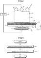
- FIG. 2 is a schematic configuration diagram of a composite material molding device 20 used for the composite material molding method according to the first embodiment of the present invention.
- the Y-axis direction in FIG. 1 matches a Y-axis direction in FIG. 2
- X-axis directions, Y-axis directions, and Z-axis directions match one another.
- the composite material molding device 20 includes a pressing head 30, a magnetic field coil 40, and a control unit 50.
- the composite material molding device 20 impregnates the reinforcing fibers 12 with the resin 14, and causes the resin 14 to react while a pre-reaction composite material 10 in which the conductive wire-shaped materials 16 are arranged are molded into a predetermined size and a predetermined shape at the magnetic field application step S14 described later.
- the pre-reaction composite material 10 is, for example, a prepreg of the composite material.
- the composite material 10 is molded in a manner that, in the composite material molding device 20, the composite material 10 is disposed on the upper side in the vertical direction of a flat table 22 extending in an XY plane direction that is orthogonal to a direction along the Z-axis direction in FIG. 2 as the vertical direction and that is the horizontal direction.
- the vertical direction and the thickness direction of the composite material 10 match each other in the Z-axis direction.
- the lower side of the composite material 10 in the vertical direction is referred to as "one side”
- the upper side of the composite material 10 in the vertical direction is referred to as "other side”.
- predetermined region 18 a region of the composite material 10 that is pressed and heated by the pressing head 30 and the magnetic field coil 40 is referred to as "predetermined region 18".
- the composite material 10 is not limited to the form of such arrangement, and any arrangement may be employed.
- the predetermined region 18 is not limited to a partial region of the composite material 10 as indicated in the first embodiment, and may be the entire region of the composite material 10.
- the flat table 22 is made of a material transparent to the magnetic field 42 applied by the magnetic field coil 40, that is, a material with which eddy current is not hardly induced inside by the magnetic field 42 applied by the magnetic field coil 40 and heat is not hardly generated inside in accordance with the magnetic field 42 applied by the magnetic field coil 40.
- a material transparent to the magnetic field 42 applied by the magnetic field coil 40 that is, a material with which eddy current is not hardly induced inside by the magnetic field 42 applied by the magnetic field coil 40 and heat is not hardly generated inside in accordance with the magnetic field 42 applied by the magnetic field coil 40.
- a PEEK resin and ceramics both of which are transparent to the magnetic field 42 and have high pressure resistance and thermal resistance, are preferred.
- the pressing head 30 is provided to face the other side of the predetermined region 18 of the composite material 10, and is provided to be opposed to the magnetic field coil 40 in the vertical direction through the composite material 10 and the flat table 22.
- the pressing head 30 presses the predetermined region 18 of the composite material 10 from the other side of the composite material 10.
- the pressing head 30 includes a pressing head main body 32.
- the pressing head main body 32 is formed from a material transparent to the magnetic field 42 applied by the magnetic field coil 40.
- As the material forming the pressing head main body 32 PEEK resin and ceramics, which are materials transparent to the magnetic field 42 and having high pressure resistance and thermal resistance, are preferred.
- the pressing head main body 32 is provided with a pressing cylinder (not shown) on the upper side in the vertical direction in FIG. 2 , and the pressing cylinder is electrically connected to the control unit 50.
- the pressing head 30 can move up and down in the vertical direction with respect to the composite material 10, and can change pressure applied to the composite material 10 downward in the vertical direction.
- the pressing head 30 presses the predetermined region 18 of the composite material 10 with preferably 200 kPa or more and 800 kPa or less, more preferably 300 kPa or more and 600 kPa or less.
- the magnetic field coil 40 is provided to face one side of the predetermined region 18 of the composite material 10, and is provided to be opposed to the pressing head 30 in the vertical direction through the flat table 22 and the composite material 10.
- the magnetic field coil 40 applies the magnetic field 42 to the predetermined region 18 of the composite material 10 from one side of the composite material 10.
- the magnetic field coil 40 in which one coil is disposed is exemplified, but a plurality of coils may be arranged into a predetermined shape, that is, a square shape.
- the magnetic field coil 40 applies the magnetic field 42 to a region equivalent to the region in the horizontal direction in which the coil is disposed.
- the region in which the magnetic field coil 40 applies the magnetic field 42 corresponds to the predetermined region 18 of the composite material 10.
- the center axis of the coil included in the magnetic field coil 40 is oriented in a direction intersecting the plane on which the composite material 10 extends.
- the magnetic field coil 40 generates the magnetic field 42 along a direction intersecting the plane on which the reinforcing fiber 12 are arranged, thereby generating the magnetic field 42 along a direction intersecting a plane formed by a conductive loop by the reinforcing fibers 12 and the conductive wire-shaped materials 16 formed inside the composite material 10.
- the magnetic field coil 40 is disposed such that an end portion of the magnetic field coil 40 on the upper side in the vertical direction is away from the surface of the composite material 10 on one side with a predetermined distance. As the predetermined distance, 1.5 cm is exemplified.
- a coil included in the magnetic field coil 40 have a center axis oriented in a direction along the vertical direction.
- the magnetic field coil 40 generates the magnetic field 42 along the direction orthogonal to the plane on which the reinforcing fibers 12 are arranged, thereby generating the magnetic field 42 along a direction orthogonal to the plane formed by a conductive loop by the reinforcing fibers 12 and the conductive wire-shaped materials 16 formed inside the composite material 10.
- the magnetic field coil 40 applies the magnetic field 42 along the direction orthogonal to the plane on which the conductive loop is formed, eddy current can be efficiently induced in the conductive loop, and hence heat can be efficiently generated. Consequently, the magnetic field coil 40 can efficiently heat the predetermined region 18 of the composite material 10.
- the magnetic field coil 40 is electrically connected to the control unit 50. Under control of the control unit 50, the magnetic field coil 40 can change the magnitude and the frequency of the magnetic field 42 applied to the composite material 10 upward in the vertical direction. It is preferred that the magnetic field coil 40 apply a high frequency magnetic field of 900 kHz or more to the predetermined region 18 of the composite material 10.
- the control unit 50 is electrically connected to a pressing cylinder provided in the pressing head main body 32.
- the control unit 50 is electrically connected to the magnetic field coil 40.
- the control unit 50 controls the pressing cylinder to control the pressing head 30, thereby being capable of controlling the relative position of the pressing head 30 in the vertical direction with respect to the composite material 10 and the pressure applied to the composite material 10 downward in the vertical direction.
- the control unit 50 can control the magnitude and the frequency of the magnetic field 42 applied by the magnetic field coil 40, thereby being capable of controlling heating temperature, temperature increase rate, and heating time of the heating of the composite material 10 depending on the specific resin composition of the composite material 10.
- the control unit 50 includes a storage unit and a processing unit.
- the storage unit includes a storage device such as a RAM, a ROM, and a flash memory, and stores therein software programs processed by the processing unit and data to be referred to by the software programs.
- the storage unit also functions as a storage area in which the processing unit temporarily stores processing results.
- the processing unit reads and processes software programs from the storage unit to exhibit functions corresponding to the contents of the software programs, specifically, various functions capable of executing the composite material molding method by the composite material molding device 20.
- the composite material molding device 20 may be provided with a movement mechanism (not shown) for synchronously changing the position of the pressing head 30 in the horizontal direction with respect to the composite material 10 and the position of the magnetic field coil 40 in the horizontal direction with respect to the composite material 10.
- the movement mechanism is controlled by the control unit 50, and can move the predetermined region 18, which is a region pressed by the pressing head 30 and a region applied with the magnetic field 42 by the magnetic field coil 40, in the composite material 10 during the molding by the composite material molding device 20.
- the control unit 50 can determine as needed where the predetermined region 18 has moved in the composite material 10.
- FIG. 3 is a flowchart of the composite material molding method according to the first embodiment of the present invention.
- the composite material molding method according to the first embodiment is described with reference to FIG. 3 .
- the composite material molding method according to the first embodiment is executed by the composite material molding device 20.
- the composite material molding method according to the first embodiment includes a conductive wire-shaped material arrangement step S12 and a magnetic field application step S14.
- the conductive wire-shaped material arrangement step S12 is a step at which the conductive wire-shaped materials 16 are added and arranged in a pre-reaction composite material 10, which have the reinforcing fibers 12 extending in one direction, in the plane on which the reinforcing fibers 12 in the composite material 10 are arranged in the direction intersecting the reinforcing fibers 12 so as to have the intervals d wider than the reinforcing fibers 12.
- the conductive wire-shaped materials 16 are interwoven into the composite material 10, so that the plurality of conductive wire-shaped materials 16 are arranged in the pre-reaction composite material 10.
- a conductive loop can be formed inside the composite material 10 by the reinforcing fibers 12 and the conductive wire-shaped material 16.
- the region in which the conductive wire-shaped materials 16 are provided becomes a region in which a conductive loop is formed inside the composite material 10 by the reinforcing fibers 12 and the conductive wire-shaped material 16 irrespective of regions of the composite material 10.
- the region in which the conductive wire-shaped materials 16 are provided becomes a region in which sufficient eddy current is induced inside the composite material 10 by the conductive loop formed by the reinforcing fibers 12 and the conductive wire-shaped materials 16 in response to the application of the magnetic field 42 and heat is generated irrespective of regions of the composite material 10.
- the composite material 10 becomes the state in which the occurrence of temperature unevenness in the composite material 10 during heating is reduced.
- the composite material 10 becomes the state in which the occurrence of strength unevenness during reaction of the resin 14 is reduced, that is, the state in which a high quality composite material 10 can be obtained.
- the conductive wire-shaped materials 16 are interwoven into the composite material 10.
- the conductive wire-shaped materials 16 can be arranged in the state of being more reliably in contact with the reinforcing fibers 12, and a conductive loop is more reliably formed inside the composite material 10.
- the conductive wire-shaped materials 16 can become the state in which sufficient eddy current is more reliably induced inside the composite material 10 by the conductive loop formed between the conductive wire-shaped materials 16 and the reinforcing fibers 12 in response to the application of the magnetic field 42, and hence can become the state in which the occurrence of temperature unevenness in the composite material 10 during heating is reduced.
- a step for executing the magnetic field application step S14 for the pre-reaction composite material 10 in which the conductive wire-shaped materials 16 are arranged is executed.
- a step for disposing the pre-reaction composite material 10 on the upper side of the flat table 22 in the vertical direction is executed.
- a step for pressing the pre-reaction composite material 10 disposed on the flat table 22 by the pressing head 30 is executed.
- the control unit 50 moves the pressing head 30 to a position facing the other side of the pre-reaction composite material 10 in the vertical direction before reaction in which the conductive wire-shaped materials 16 are arranged, so that the pressing head 30 is oriented to the predetermined region 18 of the composite material 10.
- the control unit 50 presses the predetermined region 18 of the composite material 10 from the other side of the predetermined region 18 while pushing the pressing head 30 against the other side of the predetermined region 18 of the composite material 10.
- the magnetic field application step S14 is a step for applying a magnetic field 42 to the composite material 10 in which the conductive wire-shaped materials 16 are arranged at the conductive wire-shaped material arrangement step S12 in a direction intersecting the plane on which the reinforcing fibers 12 are arranged.
- the control unit 50 moves and disposes the magnetic field coil 40 to a position facing one side of the predetermined region 18 of the composite material 10 disposed on the flat table 22 in the vertical direction and pressed by the pressing head 30 such that the magnetic field coil 40 is oriented to the predetermined region 18 of the composite material 10.
- the control unit 50 causes current to flow through the magnetic field coil 40 such that the magnetic field 42 is applied by the magnetic field coil 40 from one side of the composite material 10 to heat the predetermined region 18 of the composite material 10.
- the magnetic field 42 is generated along a direction intersecting the plane on which the conductive loop is formed by the reinforcing fibers 12 and the conductive wire-shaped materials 16 formed inside the composite material 10 at the conductive wire-shaped material arrangement step S12.
- the conductive loop is applied with the magnetic field 42 along the direction orthogonal to the plane on which the conductive loop is formed, and hence eddy current is efficiently induced, and heat can be efficiently generated. Consequently, at the magnetic field application step S14, the predetermined region 18 of the composite material 10 can be efficiently heated.
- the composite material molding method according to the first embodiment and the composite material 10 formed by this method have the configurations described above.
- a conductive loop is formed by the reinforcing fibers 12 and the conductive wire-shaped materials 16 inside the composite material 10, and hence sufficient eddy current is induced inside the composite material 10 in response to the application of the magnetic field 42 irrespective of regions of the composite material 10.
- the composite material molding method according to the first embodiment and the composite material 10 formed by this method can reduce the occurrence of strength unevenness in the composite material 10 obtained by causing the resin 14 to react, and can thus obtain the high quality composite material 10.
- the conductive wire-shaped materials 16 be interwoven into the composite material 10 such that the plurality of conductive wire-shaped materials 16 are arranged in the pre-reaction composite material 10.
- a conductive loop is more reliably formed inside the composite material 10. Consequently, sufficient eddy current is more reliably induced inside the composite material 10 in response to the application of the magnetic field 42, and hence the occurrence of temperature unevenness in the composite material 10 during heating can be further reduced.
- FIG. 4 is a diagram illustrating an example of a state of a composite material 60 during or after processing by a composite material molding method according to a second embodiment of the present invention.
- the composite material 60 during or after processing by the composite material molding method according to the second embodiment is different from the composite material 10 during or after processing by the composite material molding method according to the first embodiment in that the intervals of the conductive wire-shaped materials 16 are changed.
- the other configurations in the composite material 60 during or after processing by the composite material molding method according to the second embodiment are the same as those of the composite material 10 during or after processing by the composite material molding method according to the first embodiment.
- Conductive wire-shaped materials 66 in the composite material 60 according to the second embodiment are described below with reference symbols different from those of the conductive wire-shaped materials 16 in the composite material 10 according to the first embodiment in order to distinguish therefrom.
- the same configurations as in the composite material 10 during or after processing by the composite material molding method according to the first embodiment are denoted by the same reference symbol group as in the first embodiment, and detailed descriptions thereof are omitted.
- a composite material molding device 20 used for the composite material molding method according to the second embodiment of the present invention has the same configurations as in the composite material molding device 20 used for the composite material molding method according to the first embodiment of the present invention. The same configurations are denoted by the same reference symbol group as in the first embodiment, and detailed descriptions thereof are omitted.
- the composite material 60 includes the reinforcing fibers 12, the resin 14, and conductive wire-shaped materials 66.
- the conductive wire-shaped material 66 the same material as the conductive wire-shaped material 16 according to the first embodiment is exemplified.
- the plurality of conductive wire-shaped materials 66 are arranged inside the composite material 60 through a conductive wire-shaped material arrangement step S12 described later included in the composite material molding method according to the second embodiment of the present invention, and are disposed in a plane on which the reinforcing fibers 12 of the composite material 60 are arranged in a direction intersecting the reinforcing fibers 12.
- the conductive wire-shaped materials 66 are disposed to extend along the Y-axis direction, which is a direction orthogonal to the direction in which the reinforcing fibers 12 extend. As illustrated in FIG. 4 , the conductive wire-shaped materials 66 are disposed at a center region of the composite material 60 so as to be interwoven at intervals d1 wider than the intervals of the reinforcing fibers 12 in the X-axis direction. As illustrated in FIG. 4 , the conductive wire-shaped materials 66 are interwoven in peripheral regions of the composite material 60 at intervals d2 wider than the intervals d1 in the X-axis direction.
- the conductive wire-shaped materials 66 are disposed so as to be denser at the center region in which eddy current is not relatively easily induced than the peripheral regions in which eddy current is relatively easily induced.
- the conductive wire-shaped materials 66 more easily cause sufficient eddy current inside the composite material 60 particularly at the center region of the composite material 60, and hence the occurrence of temperature unevenness in the composite material 60 during heating can be further reduced.
- the composite material molding method according to the second embodiment is executed by the composite material molding device 20 similarly to the composite material molding method according to the first embodiment.
- the composite material molding method according to the second embodiment is different from the composite material molding method according to the first embodiment in changing the intervals of the arrangement of the conductive wire-shaped materials 16 arranged at the conductive wire-shaped material arrangement step S12.
- the composite material molding method according to the second embodiment and the composite material 60 molded by the method have the configurations as described above, and hence exhibit the same actions and effects as in the composite material molding method according to the first embodiment and the composite material 10 molded by the method.
- the intervals d2 of the conductive wire-shaped materials 66 at the peripheral regions of the composite material 60 are larger than the intervals d1 of the conductive wire-shaped materials 66 at the center region of the composite material 60.
- FIG. 5 is a diagram illustrating an example of a composite material 70 processed by a composite material molding method according to a third embodiment of the present invention.
- FIG. 6 is a schematic configuration diagram of a composite material molding device 80 used for the composite material molding method according to the third embodiment of the present invention.
- the composite material molding device 80 according to the third embodiment is different from the composite material molding method according to the first embodiment in that the composite material 10 to be processed is changed to the composite material 70, and different from the composite material molding device 20 used for the composite material molding method in that the pressing head 30 is changed to a pressing head 90.
- the other configurations in the composite material molding device 80 according to the third embodiment are the same as in the composite material molding device 20 according to the first embodiment.
- a predetermined region 78 in the composite material 70 according to the third embodiment is described with a different reference symbol in order to be distinguished from the predetermined region 18 in the composite material 10 according to the first embodiment.
- a pressing head main body 92 in the pressing head 90 according to the third embodiment is described with a different reference symbol in order to be distinguished from the pressing head main body 32 in the pressing head 30 according to the first embodiment.
- the other configurations in the composite material 70 and the composite material molding device 80 according to the third embodiment that are the same as in the first embodiment are denoted by the same reference symbol group as in the first embodiment, and detailed descriptions thereof are omitted.
- the composite material 70 has the reinforcing fibers 12 and the resin 14.
- the composite material 70 is different from the composite material 10 according to the first embodiment in that the conductive wire-shaped materials 16 are not arranged.
- the composite material molding device 80 includes a pressing head 90, a magnetic field coil 40, and a control unit 50.
- the control unit 50 according to the third embodiment controls the pressing head 90 instead of the control unit 50 according to the first embodiment that controls the pressing head 30.
- the composite material molding device 80 causes the resin 14 to react while molding a pre-reaction composite material 70, in which the reinforcing fibers 12 are impregnated with the resin 14, into a predetermined size and a predetermined shape.
- FIG. 7 is a rear diagram of the pressing head 90 used for the composite material molding method according to the third embodiment of the present invention.
- the rear diagram of the pressing head 90 illustrated in FIG. 7 is a diagram of a surface of the pressing head 90 on the side to face the composite material 70 as seen from the side of the composite material 70 upward in the vertical direction.
- the pressing head 90 includes a pressing head main body 92 and conductive wire-shaped materials 96.
- the pressing head main body 92 is different from the pressing head main body 32 according to the first embodiment in that the conductive wire-shaped materials 96 are arranged.
- the other configurations in the pressing head main body 92 are the same as in the pressing head main body 32 according to the first embodiment.
- the conductive wire-shaped materials 96 are provided on the side of the pressing head main body 92 that is to face the composite material 70 so as to be arranged along the direction intersecting the reinforcing fiber 12 with intervals D wider than the intervals of the reinforcing fibers 12 in a planar direction in which the reinforcing fibers 12 are arranged.
- the conductive wire-shaped materials 96 are arranged to extend along the Y-axis direction, which is a direction orthogonal to the direction in which the reinforcing fibers 12 extend, with equal intervals D in the X-axis direction.
- the conductive wire-shaped material 96 the same material as the conductive wire-shaped material 16 according to the first embodiment is exemplified.
- the pressing head 90 is provided with the conductive wire-shaped material 96 on the side of the pressing head main body 92 to face the composite material 70, and hence can press the composite material 70 while pushing the conductive wire-shaped material 96 against the predetermined region 78 of the composite material 70.
- the conductive wire-shaped materials 96 are disposed in contact with the reinforcing fibers 12.
- the reinforcing fibers 12 and the conductive wire-shaped materials 96 form a conductive loop in a surface layer region inside the composite material 70 in the predetermined region 78.
- the conductive wire-shaped materials 96 contact the reinforcing fibers 12 to form a conductive loop, and hence two or more conductive wire-shaped materials 96, that is, a plurality of conductive wire-shaped materials 96, need to be provided inside the composite material 70.
- the conductive loop formed by the reinforcing fibers 12 and the conductive wire-shaped materials 96 induce sufficient eddy current inside the composite material 70 by the magnetic field 42 applied at the magnetic field application step S14. Consequently, the conductive loop formed by the reinforcing fibers 12 and the conductive wire-shaped materials 96 can generate sufficient heat inside the composite material 70 in the predetermined region 78.
- a composite material molding method according to the third embodiment which is a processing method executed by the composite material molding device 80 according to the third embodiment, is different from the composite material molding method according to the first embodiment in that the conductive wire-shaped material arrangement step S12 is changed as follows.
- a conductive wire-shaped material arrangement step S12 according to the third embodiment is different in that the interweaving of the conductive wire-shaped materials 16 into the composite material 10 at the conductive wire-shaped material arrangement step S12 according to the first embodiment is changed to the pressing of the predetermined region 78 in the composite material 70 by the pressing head 90 in which the conductive wire-shaped materials 96 are provided.
- the predetermined region 78 of the composite material 70 is pressed by the pressing head 90 to which the conductive wire-shaped materials 96 are provided on the side to face the composite material 70, and the conductive wire-shaped materials 96 are pushed against the predetermined region 78 of the composite material 70 such that the conductive wire-shaped materials 96 are brought into contact with the reinforcing fibers 12, thereby arranging the plurality of conductive wire-shaped materials 96 in the predetermined region 78 of the pre-reaction composite material 70.
- the composite material 70 is pressed by the pressing head 90 to which the conductive wire-shaped materials 96 are provided on the side to face the composite material 70.
- the conductive wire-shaped material arrangement step S12 according to the third embodiment even when the conductive wire-shaped materials 96 are not interwoven inside the composite material 70, a conductive loop is formed by the reinforcing fibers 12 and the conductive wire-shaped materials 96 inside the composite material 70.
- the predetermined region 78 as a region pressed against the conductive wire-shaped materials 96 becomes the state in which sufficient eddy current is induced inside the composite material 70 by the conductive loop formed by the reinforcing fibers 12 and the conductive wire-shaped materials 96 in response to the application of the magnetic field 42 irrespective of regions of the composite material 70, and heat is generated.
- the composite material 70 becomes the state in which the occurrence of temperature unevenness in the composite material 70 during heating is reduced.
- the composite material 70 becomes the state in which the occurrence of strength unevenness when the resin 14 is caused to react is reduced, that is, the state in which a high quality composite material 70 can be obtained.
- the pressing head 90 and the composite material molding device 80 according to the third embodiment and the composite material molding method using the composite material molding device 80 have the configurations described above, and hence exhibit the same actions and effects as those of the composite material molding method according to the first embodiment and the composite material 10 formed by the method.
- the pressing head 90 and the composite material molding device 80 according to the third embodiment and the composite material molding method using the composite material molding device 80 press the composite material 70 by the pressing head 90 to which the conductive wire-shaped materials 96 are provided on the side to face the composite material 70.
- the composite material molding device 80 even when the conductive wire-shaped materials 96 are not interwoven inside the composite material 70, a conductive loop is formed inside the composite material 70. Consequently, sufficient eddy current is induced inside the composite material 70 in response to the application of the magnetic field 42, and hence the occurrence of temperature unevenness in the composite material 70 during heating can be reduced.
- FIG. 8 is a rear diagram of a pressing head 110 used for a composite material molding method according to a fourth embodiment of the present invention.
- the rear diagram of the pressing head 110 illustrated in FIG. 8 is a diagram of a surface of the pressing head 110 on the side to face the composite material 70 as seen from the side of the composite material 70 upward in the vertical direction.
- the composite material molding device 100 according to the fourth embodiment is different from the composite material molding device 80 used for the composite material molding method according to the third embodiment in that the pressing head 90 is changed to the pressing head 110. Note that the other configurations in the composite material molding device 100 according to the fourth embodiment are the same as those in the composite material molding device 80 according to the third embodiment.
- a pressing head main body 112 in the pressing head 110 according to the fourth embodiment is described with a different reference symbol in order to be distinguished from the pressing head main body 92 in the pressing head 90 according to the third embodiment.
- the other configurations in the composite material molding device 100 according to the fourth embodiment that are the same as in the third embodiment are denoted by the same reference symbol group as in the third embodiment, and detailed descriptions thereof are omitted.
- the composite material molding device 100 includes a pressing head 110, a magnetic field coil 40, and a control unit 50.
- the control unit 50 according to the fourth embodiment controls the pressing head 110 instead of controlling the pressing head 90 by the control unit 50 according to the third embodiment.
- the composite material molding device 100 causes the resin 14 to react while molding the pre-reaction composite material 70, in which the reinforcing fibers 12 are impregnated with the resin 14, into a predetermined size and a predetermined shape.
- the pressing head 110 includes a pressing head main body 112 and a conductive wire-shaped material 116.
- the pressing head main body 112 is different from the pressing head main body 92 according to the third embodiment in that the intervals of the arrangement of the conductive wire-shaped materials 96 are changed.
- the conductive wire-shaped material 116 in the pressing head main body 112 according to the fourth embodiment is described with a different reference symbol in order to be distinguished from the conductive wire-shaped material 96 in the pressing head main body 92 according to the third embodiment.
- the other configurations in the pressing head main body 112 are the same as in the pressing head main body 92 according to the third embodiment.
- the conductive wire-shaped materials 116 are provided on the side of the pressing head main body 112 to face the composite material 70 so as to be arranged along the direction intersecting the reinforcing fibers 12 in a planar direction in which the reinforcing fibers 12 are arranged.
- the conductive wire-shaped materials 116 are disposed to extend along the Y-axis direction, which is a direction orthogonal to the direction in which the reinforcing fibers 12 extend. As illustrated in FIG.
- the conductive wire-shaped materials 116 are provided and arranged in a center region of the surface of the pressing head main body 112 on the side to face the composite material 70 with intervals D1 wider than the intervals of the reinforcing fibers 12 in the X-axis direction. As illustrated in FIG. 8 , the conductive wire-shaped materials 116 are provided and arranged in peripheral regions of the pressing head main body 112 on the side to face the composite material 70 with intervals D2 wider than the intervals D1 in the X-axis direction. As the conductive wire-shaped material 116, the same material as the conductive wire-shaped material 96 according to the third embodiment is exemplified.
- the pressing head 110 presses the predetermined region 78 of the composite material 70, thereby pressing the conductive wire-shaped materials 116 such that the conductive wire-shaped materials 116 are denser at the center region of the composite material 70 in which eddy current is not relatively easily induced than the peripheral regions of the composite material 70 in which eddy current is relatively easily induced.
- the pressing head 110 causes the conductive wire-shaped materials 116 to induce sufficient eddy current inside the predetermined region 78 of the composite material 70 particularly at the center region of the predetermined region 78 of the composite material 70, and hence the occurrence of temperature unevenness in the composite material 70 during heating can be further reduced.
- a composite material molding method according to the fourth embodiment which is a processing method executed by the composite material molding device 100 according to the fourth embodiment, is different from the composite material molding method according to the third embodiment in that the conductive wire-shaped material arrangement step S12 is changed as follows.
- the conductive wire-shaped material arrangement step S12 according to the fourth embodiment is different from the conductive wire-shaped material arrangement step S12 according to the third embodiment in that the pressing head 90 for pressing the predetermined region 78 of the composite material 70 is changed to the pressing head 110.
- the conductive wire-shaped material arrangement step S12 according to the fourth embodiment is different from the conductive wire-shaped material arrangement step S12 according to the third embodiment in that the intervals of the conductive wire-shaped materials 96 to be pushed against the predetermined region 78 of the composite material 70 are changed.
- the pressing head 110, the composite material molding device 100, and the composite material molding method using the composite material molding device 100 according to the fourth embodiment have the configurations described above, and hence exhibit the same actions and effects as those of the pressing head 90, the composite material molding device 80, and the composite material molding method using the composite material molding device 80 according to the third embodiment.
- the intervals D2 of the conductive wire-shaped materials 116 at the peripheral regions are larger than the intervals D1 of the conductive wire-shaped materials 116 at the center region on the surface of the pressing head main body 112 on the side to face the composite material 70 that is pressed against the predetermined region 78 of the composite material 70.
- the composite material molding device 100 and the composite material molding method by the composite material molding device 100 according to the fourth embodiment, particularly at the center region of the predetermined region 78 of the composite material 70, sufficient eddy current is induced inside the predetermined region 78 of the composite material 70, and hence the occurrence of temperature unevenness in the composite material 70 during heating can be further reduced.
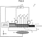
- FIG. 9 is a schematic configuration diagram of a composite material molding device 120 used for a composite material molding method according to a fifth embodiment of the present invention.
- the configurations in the composite material molding device 120 according to the fifth embodiment that are the same as in the third and fourth embodiments are denoted by the same reference symbol group as in the third and fourth embodiments, and detailed descriptions thereof are omitted.
- the composite material molding device 120 illustrated in FIG. 9 impregnates the reinforcing fibers 12 extending in one direction with the resin 14, and causes the resin 14 to react while sequentially molding a pre-reaction composite material 70 in which the elongated conductive wire-shaped materials 16 are not arranged in the same direction as the direction in which the reinforcing fibers 12 extend into a predetermined size and a predetermined shape along the longitudinal direction.
- the pre-reaction composite material 70 is, for example, a prepreg of the composite material.
- the composite material molding device 120 includes a composite material supply unit 122, a compression roller 124, a consolidation roller 126, and a control unit 128.
- the composite material supply unit 122 supplies the composite material 70 having the reinforcing fibers 12 extending in an X-axis direction as one direction onto a flat table 22 along a +X direction of the X-axis direction as the direction in which the reinforcing fibers 12 extend.
- the composite material supply unit 122 supplies the composite material 70 in a non-pressed state 130 where the composite material 70 is not pressed in the vertical direction, which is a direction orthogonal to the plane on which the reinforcing fibers 12 are arranged, that is, in the Z-axis direction.
- both of the compression roller 124 and the consolidation roller 126 are provided on the downstream side of the supply of the composite material 70 by the composite material supply unit 122 in parallel to the plane on which the reinforcing fibers 12 are arranged and along the Y-axis direction that is a direction intersecting the reinforcing fibers 12.
- the compression roller 124 rotates in the counterclockwise direction in FIG. 9 to convey the composite material 70 in the non-pressed state 130 supplied from the composite material supply unit 122 toward the +X direction of the X-axis direction on the downstream side while pressing the composite material 70 in the vertical direction such that the composite material 70 becomes a compressed state 132.
- the consolidation roller 126 rotates in the counterclockwise direction in FIG.
- the compression roller 124 and the consolidation roller 126 constitute at least two electroconductive rollers arranged at a distance from each other in the X-axis direction as the direction in which the reinforcing fibers 12 extend.
- the electroconductive rollers have the two rollers, that is, the compression roller 124 and the consolidation roller 126, but the present invention is not limited thereto. Three or more electroconductive rollers may be provided to set three or more stages of the pressing state of the composite material 70.
- the electroconductive roller for example, it is preferred to use metal material having electric conductivity, inorganic material having electric conductivity such as ceramics and carbon-based material, and organic material having electric conductivity.
- the electric conductive material constituting the electroconductive roller is metal material having electric conductivity, that is, when the electroconductive roller is a metal roller, the metal material having electric conductivity is preferably a metal material having high electric conductivity.
- the metal material having high electric conductivity for example, it is preferred to use aluminum, iron, copper, silver, and gold.
- the magnetic field coil 40 is provided in a region between the compression roller 124 and the consolidation roller 126, which constitute at least two electroconductive rollers, at a position opposed to the Z-axis direction as the vertical direction through the composite material 70 and the flat table 22.
- the magnetic field coil 40 applies the magnetic field 42 to the region between the compression roller 124 and the consolidation roller 126 in a direction intersecting the plane on which the reinforcing fibers 12 are arranged.
- the magnetic field coil 40 is provided in the region between the compression roller 124 and the consolidation roller 126, but the present invention is not limited thereto.
- the magnetic field coil 40 may be freely provided in a region between two electroconductive rollers constituting at least two electroconductive rollers.
- the control unit 128 is electrically connected to the magnetic field coil 40, the composite material supply unit 122, a drive mechanism for the compression roller 124, and a drive mechanism for the consolidation roller 126.
- the control unit 128 has the same hardware as that of the control unit 50 according to the first embodiment, and controls the magnetic field coil 40 by the same method as that of the control unit 50 according to the first embodiment.
- the control unit 128 controls the composite material supply unit 122 to control the supply amount, supply speed, and number of supplied composite materials 70.
- the control unit 128 controls the magnitude of the pressurization in the vertical direction, that is, controls the pressure to control the compression processing of the composite material 70 and the conveyance speed of the composite material 70 in accordance with the rotational driving of the compression roller 124.
- the control unit 128 controls the magnitude of the pressurization in the vertical direction, that is, the consolidation processing of the composite material 70 and the conveyance speed of the composite material 70 in accordance with the rotational driving of the consolidation roller 126.
- a composite material molding method according to the fifth embodiment which is a processing method executed by the composite material molding device 120 according to the fifth embodiment, is different from the composite material molding method according to the third embodiment in that the conductive wire-shaped material arrangement step S12 is changed as follows.
- the conductive wire-shaped material arrangement step S12 according to the fifth embodiment is different from the conductive wire-shaped material arrangement step S12 according to the third embodiment in that the compression roller 124 and the consolidation roller 126 are pushed against the composite material 70 instead of pressing the predetermined region 78 of the composite material 70 by the pressing head 90 to push the conductive wire-shaped materials 96 against the predetermined region 78 of the composite material 70.
- Both of the compression roller 124 and the consolidation roller 126 pushed against the composite material 70 are made of electric conductive material and have electric conductivity, and hence have a conductive loop forming function similarly to the conductive wire-shaped material 96 according to the third embodiment.
- the pressed regions of the composite material 70 by the compression roller 124 and the consolidation roller 126 move in the -X direction of the X-axis direction on the opposite side of the conveyance direction of the composite material 70 at the same speed as the conveyance speed of the composite material 70.
- the magnetic field application step S14 according to the fifth embodiment is obtained by changing, due to the change of the conductive wire-shaped material arrangement step S12 according to the fifth embodiment, the region applied with the magnetic field 42 to the region between the compression roller 124 and the consolidation roller 126 pushed against the composite material 70.
- the region in the composite material 70 in which the conductive loop is formed and the region in which the magnetic field 42 is applied move in the -X direction of the X-axis direction on the opposite side of the conveyance direction of the composite material 70 at the same speed as the conveyance speed of the composite material 70.
- the composite material molding method according to the fifth embodiment further includes a composite material supply step and a composite material compression step and a composite material consolidation step.
- the composite material supply step is a step at which the composite material supply unit 122 supplies the composite material 70 having the reinforcing fibers 12 extending in one direction onto the flat table 22 along a +X direction as the X-axis direction, which is the direction in which the reinforcing fibers 12 extend.
- the composite material compression step is a step at which the compression roller 124 is in a non-pressed state 130 supplied from the composite material supply unit 122, and the composite material 70 in the state before reaction of the resin 14 before the magnetic field is applied for heating at the magnetic field application step S14 is conveyed in the +X direction of the X-axis direction on the downstream side while pressing the composite material 70 in the vertical direction to be in a compressed state 132.
- the composite material consolidation step is a step at which the consolidation roller 126 becomes a compressed state 132 by the compression roller 124, and the composite material 70 after reaction of the resin 14 after the magnetic field is applied for heating at the magnetic field application step S14 is conveyed in the X-axis direction on the downstream side while pressing the composite material 70 in the vertical direction to be in a consolidated state 134 in which the resin 14 of the composite material 70 that has been identifiable to be separated during supply from the composite material supply unit 122 is integrated so as to be unidentifiable to be separated.
- the composite material molding device 120 and the composite material molding method by the composite material molding device 120 according to the fifth embodiment have the configurations described above, and hence, similarly to the third and fourth embodiments, even when the conductive wire-shaped materials 96 are not interwoven inside the composite material 70, a conductive loop is formed inside the composite material 70 through the compression roller 124 and the consolidation roller 126 served as electroconductive rollers. Thus, sufficient eddy current is induced inside the composite material 70 in response to the application of the magnetic field 42 to the conductive loop, and hence the occurrence of temperature unevenness in the composite material 70 during heating can be reduced.
- the composite material 70 is conveyed while being pressed by the compression roller 124 and the consolidation roller 126 served as electroconductive rollers, and hence the pressed region in the composite material 70 and the region in the composite material 70 in which the conductive loop is formed can be moved. Consequently, the elongated composite materials 70 in which the conductive wire-shaped materials 96 are not interwoven in the composite materials 70 can be sequentially molded as appropriate.
- a composite material molding method is obtained by selecting, in each of the first to fifth embodiments, a commingled material that is the mixture of reinforcing fibers 12 and thermoplastic resin fibers served as the resin 14 as a composite material to be molded.
- the commingled material includes a commingled knitted material in which the reinforcing fibers 12 and the thermoplastic resin fibers are interwoven in a knitted manner.
- the composite material molding method and the commingled material as a composite material molded by the method according to the sixth embodiment have the configurations described above, and hence exhibit the same actions and effects as in the first to fifth embodiments.
Landscapes
- Engineering & Computer Science (AREA)
- Chemical & Material Sciences (AREA)
- Mechanical Engineering (AREA)
- Health & Medical Sciences (AREA)
- Physics & Mathematics (AREA)
- Composite Materials (AREA)
- Thermal Sciences (AREA)
- Oral & Maxillofacial Surgery (AREA)
- Organic Chemistry (AREA)
- Polymers & Plastics (AREA)
- Medicinal Chemistry (AREA)
- Electromagnetism (AREA)
- Toxicology (AREA)
- Chemical Kinetics & Catalysis (AREA)
- Materials Engineering (AREA)
- Manufacturing & Machinery (AREA)
- Moulding By Coating Moulds (AREA)
Abstract
Description
- The present invention relates to a method for molding a composite material, a composite material, a pressing head, and a device for molding a composite material.
- As light materials having high strength, a composite material in which reinforcing fibers are impregnated with a resin has been known. The composite material is used for aircraft, automobiles, and ships. As a method for manufacturing the composite material, a method has been known in which sheets of composite materials including reinforcing fibers impregnated with a resin are laminated and the laminated sheet is heated by using electromagnetic waves in the pressed state (see Patent Literature 1).
- Patent Literature 1: Japanese Patent Application Laid-open No.
2015-131430 - Composite material has conductivity in portions of reinforcing fibers. Thus, the electric conductivity of the composite material is low except for a particular direction. Accordingly, in the case where the magnetic field is used to heat the composite material instead of electromagnetic waves in the method in Patent Literature 1, the electric conductivity of the composite material is low except for a particular direction, even when the magnetic field is applied to the entire composite material, there is a problem in that sufficient eddy current is not induced inside the composite material depending on regions of the composite material, and hence a region where the composite material is not sufficiently heated occurs and temperature unevenness occurs in the composite material during heating. As a result, a composite material obtained by using the magnetic field instead of electromagnetic waves in the method in Patent Literature 1 and heating the composite material to cause the resin to react has a problem in that strength unevenness occurs and the quality is not high.
- The present invention has been made in view of the above, and it is an object thereof to provide a method for molding a composite material, a composite material, a pressing head, and a device for molding a composite material, which reduce the occurrence of temperature unevenness in a composite material during heating.
- To solve the problems described above and achieve the object, a method for molding a composite material is a method for molding a composite material including reinforcing fibers, and includes a conductive wire-shaped material arrangement step of arranging, in pre-reaction composite material, a plurality of conductive wire-shaped materials along a direction intersecting the reinforcing fibers with intervals wider than intervals of the reinforcing fibers in a plane on which the reinforcing fibers are arranged; and a magnetic field application step of applying a magnetic field in a direction intersecting the plane on which the reinforcing fibers are arranged.
- With this configuration, a conductive loop is formed by the reinforcing fibers and the conductive wire-shaped materials, and hence sufficient eddy current is induced inside the composite material in response to the application of the magnetic field irrespective of regions of the composite material. Thus, the occurrence of temperature unevenness in the composite material during heating can be reduced. Consequently, this configuration can reduce the occurrence of strength unevenness in a composite material obtained by causing a resin to react, and can obtain a high quality composite material.
- In this configuration, it is preferable that intervals of the conductive wire-shaped materials at peripheral regions of the composite material are larger than intervals of the conductive wire-shaped materials at a center region of the composite material. With this configuration, sufficient eddy current is induced inside the composite material particularly in the center region of the composite material, and hence the occurrence of temperature unevenness in the composite material during heating can be further reduced.
- In these configurations, it is preferable that the conductive wire-shaped material arrangement step includes interweaving the conductive wire-shaped materials into the composite material. With this configuration, the conductive loop is more reliably formed inside the composite material. Thus, sufficient eddy current is more reliably induced inside the composite material in response to the application of the magnetic field, and hence the occurrence of temperature unevenness in the composite material during heating can be further reduced.
- Alternatively, in these configurations, it is preferable that the conductive wire-shaped material arrangement step includes pressing the composite material by a pressing head to which the conductive wire-shaped materials are provided on a side to face the composite material. With this configuration, even when conductive wire-shaped materials are not interwoven inside the composite material, a conductive loop is formed inside the composite material. Thus, sufficient eddy current is induced inside the composite material in response to the application of the magnetic field, and hence the occurrence of temperature unevenness in the composite material during heating can be reduced.
- Alternatively, in these configurations, it is preferable that the conductive wire-shaped material arrangement step includes pressing the composite material by an electroconductive roller served as the conductive wire-shaped material, and conveying the composite material along a direction in which the reinforcing fibers extend. With this configuration, even when conductive wire-shaped materials are not interwoven into the composite material, a conductive loop is formed inside the composite material through the electroconductive roller. Thus, sufficient eddy current is induced inside the composite material in response to the application of the magnetic field, and hence the occurrence of temperature unevenness in the composite material during heating can be reduced. Furthermore, the composite material is conveyed while being pressed by the electroconductive roller. Thus, a pressed region in the composite material and a region in the composite material in which the conductive loop is formed can be moved, and hence elongated composite materials in which conductive wire-shaped materials are not interwoven can be sequentially formed as appropriate.
- In these configurations, it is preferable that the composite material is a commingled material in which the reinforcing fibers and a resin are interwoven in a knitted manner. With this configuration, a conductive loop is formed inside a commingled material in which a resin is interwoven in reinforcing fibers. Thus, sufficient eddy current is induced inside the commingled material in response to the application of the magnetic field, and hence the occurrence of temperature unevenness in the commingled material during heating can be reduced.
- To solve the problems described above and achieve the object, a composite material extending planarly includes reinforcing fibers; a resin impregnated in the reinforcing fibers; and a plurality of conductive wire-shaped materials disposed in a plane on which the reinforcing fibers are arranged along a direction intersecting the reinforcing fibers, with intervals wider than intervals of the reinforcing fibers.
- With this configuration, a conductive loop is formed by the reinforcing fibers and the conductive wire-shaped materials. Thus, sufficient eddy current is induced inside the composite material in response to the application of the magnetic field irrespective of regions of the composite material, and hence the occurrence of temperature unevenness in the composite material during heating can be reduced. Consequently, this configuration can reduce the occurrence of strength unevenness in a composite material obtained by causing a resin to react, and can obtain a high quality composite material.
- To solve the problems described above and achieve the object, a composite material extending planarly includes reinforcing fibers; a resin interwoven in a knitted manner together with the reinforcing fibers; and a plurality of conductive wire-shaped materials disposed in a plane on which the reinforcing fibers are arranged along a direction intersecting the reinforcing fibers, with intervals wider than intervals of the reinforcing fibers.
- With this configuration, a conductive loop by the reinforcing fibers and the conductive wire-shaped materials is formed inside a commingled material in which a resin is interwoven in reinforcing fiber. Thus, sufficient eddy current is induced inside the commingled material in response to the application of the magnetic field irrespective of regions of the commingled material, and hence the occurrence of temperature unevenness in the commingled material during heating can be reduced. Consequently, this configuration can reduce the occurrence of strength unevenness in a commingled material obtained by causing a resin to react, and can obtain a high quality commingled material.
- To solve the problems described above and achieve the object, a pressing head is a pressing head for pressing a composite material including reinforcing fibers, and includes a pressing head main body; and a plurality of conductive wire-shaped materials provided, on a side of the pressing head main body to face the composite material, in a planar direction in which the reinforcing fibers are arranged, with intervals wider than intervals of the reinforcing fibers along a direction intersecting the reinforcing fibers.
- With this configuration, even when conductive wire-shaped materials are not interwoven inside the composite material, a conductive loop can be formed by the reinforcing fibers and the conductive wire-shaped materials. Thus, sufficient eddy current can be induced inside the composite material in response to the application of the magnetic field irrespective of regions of the composite material, and hence the occurrence of temperature unevenness in the composite material during heating can be reduced. Consequently, this configuration can reduce the occurrence of strength unevenness in a composite material obtained by causing a resin to react, and can obtain a high quality composite material.
- To solve the problems described above and achieve the object, a device for molding a composite material includes the pressing head described above; and a magnetic field coil for applying a magnetic field in a direction intersecting the plane on which the reinforcing fibers are arranged.
- With this configuration, even when conductive wire-shaped materials are not interwoven inside the composite material, a conductive loop can be formed by the reinforcing fibers and the conductive wire-shaped materials. Thus, sufficient eddy current can be induced inside the composite material in response to the application of the magnetic field irrespective of regions of the composite material, and hence the occurrence of temperature unevenness in the composite material during heating can be reduced. Consequently, this configuration can reduce the occurrence of strength unevenness in a composite material obtained by causing a resin to react, and can obtain a high quality composite material.
- To solve the problems described above and achieve the object, a device for molding a composite material includes a composite material supply unit that supplies a composite material including reinforcing fibers along a direction in which the reinforcing fibers extend; at least two electroconductive rollers provided, on a downstream side of the composite material supplied by the composite material supply unit, in parallel to a plane on which the reinforcing fibers are arranged and along a direction intersecting the reinforcing fibers, the at least two electroconductive rollers being disposed at a distance from each other in the direction in which the reinforcing fibers extend; and a magnetic field coil for applying a magnetic field to a region between the at least two electroconductive rollers in a direction intersecting the place on which the reinforcing fibers are arranged. The electroconductive roller presses the composite material supplied by the composite material supply unit in a direction orthogonal to the plane on which the reinforcing fibers are arranged, and conveys the composite material along the direction in which the reinforcing fibers extend.
- With this configuration, even when conductive wire-shaped materials are not interwoven inside the composite material, a conductive loop is formed inside the composite material through the electroconductive roller. Thus, sufficient eddy current is induced inside the composite material in response to the application of the magnetic field to the conductive loop, and hence the occurrence of temperature unevenness in the composite material during heating can be reduced. Furthermore, the composite material is conveyed while being pressed by the electroconductive roller. Thus, a pressed region in the composite material and a region in the composite material in which the conductive loop is formed can be moved, and hence elongated composite materials in which conductive wire-shaped materials are not interwoven can be sequentially formed as appropriate.
- According to the present invention, it is possible to provide a method for molding a composite material, a composite material, a pressing head, and a device for molding a composite material, which reduce the occurrence of temperature unevenness in the composite material during heating.
-
-
FIG. 1 is a diagram illustrating an example of a state of a composite material during or after processing by a composite material molding method according to a first embodiment of the present invention. -
FIG. 2 is a schematic configuration diagram of a composite material molding device used for the composite material molding method according to the first embodiment of the present invention. -
FIG. 3 is a flowchart of the composite material molding method according to the first embodiment of the present invention. -
FIG. 4 is a diagram illustrating an example of a state of a composite material during or after processing by a composite material molding method according to a second embodiment of the present invention. -
FIG. 5 is a diagram illustrating an example of a composite material processed by a composite material molding method according to a third embodiment of the present invention. -
FIG. 6 is a schematic configuration diagram of a composite material molding device used for the composite material molding method according to the third embodiment of the present invention. -
FIG. 7 is a rear diagram of a pressing head used for the composite material molding method according to the third embodiment of the present invention. -
FIG. 8 is a rear diagram of a pressing head used for a composite material molding method according to a fourth embodiment of the present invention. -
FIG. 9 is a schematic configuration diagram of a composite material molding device used for a composite material molding method according to a fifth embodiment of the present invention. - Embodiments according to the present invention are described in detail below with reference to the drawings. Note that the present invention is not limited by the embodiments. Components in the embodiments include the ones that can be easily replaced by the skilled person and the ones that are substantially the same. Furthermore, the components described below can be combined as appropriate.
-
FIG. 1 is a diagram illustrating an example of a state of acomposite material 10 during or after processing by a composite material molding method according to a first embodiment of the present invention. Thecomposite material 10 illustrated inFIG. 1 indicates the state during processing when aresin 14 is in a state before reaction, and indicates the state after processing when theresin 14 is in a state after reaction. As illustrated inFIG. 1 , thecomposite material 10 has reinforcingfibers 12, theresin 14, and conductive wire-shapedmaterials 16. Examples of thecomposite material 10 include a material molded into a flat plate shape extending planarly in an XY plane direction illustrated inFIG. 1 , which is the horizontal direction. Note that, in the present invention, thecomposite material 10 is not limited to the form of being molded into a flat plate shape as described above, and may be molded into any shape such as a complicated shape having a curve. - In the first embodiment, most of the reinforcing
fibers 12 extend inside thecomposite material 10 in an X-axis direction illustrated inFIG. 1 , that is, in one direction in the plane on which thecomposite material 10 extends, and are arranged along a Y-axis direction illustrated inFIG. 1 , that is, along the other direction in the plane on which thecomposite material 10 extends. Thecomposite material 10 is what is called "unidirectional material". Note that the reinforcingfibers 12 are not limited to this arrangement form, and a part of the reinforcingfibers 12 may extend along a direction different from the one direction. Furthermore, for example, thecomposite material 10 may be a crossed material in which a part of the reinforcingfibers 12 are disposed inside thecomposite material 10 so as to extend along one direction in the plane on which thecomposite material 10 extends, and the remaining part of the reinforcingfibers 12 are disposed so as to extend along the other direction in the plane different from the one direction. In this case, when the reinforcingfibers 12 extending along one direction and the reinforcingfibers 12 extending along the other direction do not basically form a conductive loop inside thecomposite material 10, great actions and effects by a composite material molding method according to the embodiments of the present invention can be more remarkably obtained. - The
resin 14 is impregnated in the reinforcingfiber 12, and reacts through a magnetic field application step S14 described later included in a composite material molding method according to the first embodiment of the present invention. Examples of theresin 14 include a thermosetting resin that shows thermosetting reaction from a softened state or a semi-cured state to a cured state when heated and a thermoplastic resin that shows thermofusion reaction when heated. In the following, when the thermosetting resin and the thermoplastic resin are not distinguished for theresin 14, the thermosetting reaction of the thermosetting resin and the thermofusion reaction of the thermoplastic resin are simply referred to as "reaction". The plurality of conductive wire-shapedmaterials 16 are added and arranged inside thecomposite material 10 through a conductive wire-shaped material arrangement step S12 described later included in the composite material molding method according to the first embodiment of the present invention, and are disposed in a plane on which the reinforcingfibers 12 in thecomposite material 10 are arranged, with intervals d wider than the intervals of the reinforcingfibers 12 along a direction intersecting the reinforcingfibers 12. In the first embodiment, the form in which the conductive wire-shapedmaterials 16 are disposed and interwoven is exemplified, but the conductive wire-shapedmaterials 16 are not limited thereto and may be disposed by another method. In the first embodiment, the conductive wire-shapedmaterials 16 are disposed at equal intervals d in the X-axis direction so as to extend along the Y-axis direction, which is a direction orthogonal to the direction in which the reinforcingfibers 12 extend. - The reinforcing
fiber 12 has electric conductivity, and hence eddy current is induced inside thecomposite material 10 by amagnetic field 42 applied at the magnetic field application step S14 described later. When the eddy current is induced inside thecomposite material 10, the reinforcingfiber 12 generates heat by its own electric resistance. In other words, thecomposite material 10 generates heat inside in accordance with themagnetic field 42. Heat generated by the reinforcingfiber 12 included in thecomposite material 10 is transferred to theresin 14 included in thecomposite material 10, and contributes to the reaction of theresin 14. - The
composite material 10 is light and has high strength. As the reinforcingfibers 12, carbon fibers are exemplified in the first embodiment. However, the reinforcingfibers 12 are not limited thereto, and may be other fibers having electric conductivity, for example, metal fibers. In the first embodiment, when theresin 14 is a thermosetting resin, a resin having an epoxy resin is exemplified. When theresin 14 has an epoxy resin, theresin 14 is lighter and has higher strength, which is preferred. In the first embodiment, when theresin 14 is a thermosetting resin, a polyester resin or a vinyl ester resin are exemplified as well. In the first embodiment, when theresin 14 is a thermoplastic resin, a polyamide resin, a polypropylene resin, an acrylonitrile butadiene styrene (ABS) resin, polyetheretherketone (PEEK), polyetherketoneketone (PEKK), and polyphenylenesulfide (PPS) are exemplified. However, theresin 14 is not limited thereto, and may be another resin. - The conductive wire-shaped
material 16 has electric conductivity, and hence eddy current is induced inside thecomposite material 10 by themagnetic field 42 applied at the magnetic field application step S14 described later. The conductive wire-shapedmaterial 16 is a thin conductive material extending long in one direction. In addition to the same material as the reinforcingfiber 12, an electric conductive material (for example, metal material) such as a wire of a thin electric conductive material (for example, metal wire) is exemplified. - The conductive wire-shaped
materials 16 are disposed in contact with the reinforcingfibers 12. Thus, the reinforcingfibers 12 and the conductive wire-shapedmaterials 16 form a conductive loop inside thecomposite material 10. Note that the conductive wire-shapedmaterials 16 contact the reinforcingfibers 12 to form a conductive loop, and hence two or more conductive wire-shapedmaterials 16, that is, a plurality of conductive wire-shapedmaterials 16 need to be provided inside thecomposite material 10. The conductive loop formed by the reinforcingfibers 12 and the conductive wire-shapedmaterials 16 induces sufficient eddy current inside thecomposite material 10 by themagnetic field 42 applied at the magnetic field application step S14 described later. In this manner, the conductive loop formed by the reinforcingfibers 12 and the conductive wire-shapedmaterials 16 can generate sufficient heat inside thecomposite material 10. - The conductive wire-shaped
materials 16 are in the state capable of forming a conductive loop with the reinforcingfibers 12 inside thecomposite material 10 irrespective of regions of thecomposite material 10. Thus, the conductive wire-shapedmaterials 16 are in the state capable of inducing sufficient eddy current inside thecomposite material 10 by the conductive loop formed between the conductive wire-shapedmaterials 16 and the reinforcingfibers 12 in response to the application of themagnetic field 42 irrespective of regions of thecomposite material 10. Consequently, the conductive wire-shapedmaterials 16 can contribute to the reduction of the occurrence of temperature unevenness in thecomposite material 10 during heating. The conductive wire-shapedmaterials 16 can reduce the occurrence of strength unevenness in thecomposite material 10 obtained by causing theresin 14 to react, and hence can contribute to obtaining a highquality composite material 10. - The conductive wire-shaped
materials 16 are arranged inside thecomposite material 10 with the intervals d wider than the intervals of the reinforcingfibers 12. Thus, the number of contacts between the reinforcingfibers 12 and the conductive wire-shapedmaterials 16 can be reduced, and the cutting of the reinforcingfiber 12 due to stress concentration at a contact point of the reinforcingfiber 12 and the conductive wire-shapedmaterial 16 caused when thecomposite material 10 is pressed can be reduced. Consequently, the reduction in strength of thecomposite material 10 due to the cutting of the reinforcingfiber 12 can be reduced. - The conductive wire-shaped
materials 16 are interwoven into thecomposite material 10. Thus, the conductive wire-shapedmaterials 16 are in the state in which the conductive wire-shapedmaterials 16 more reliably contact the reinforcingfibers 12 and a conductive loop is more reliably formed inside thecomposite material 10. Consequently, the conductive wire-shapedmaterials 16 can more reliably induce sufficient eddy current inside thecomposite material 10 by the conductive loop in response to the application of themagnetic field 42, and hence can contribute to the further reduction of the occurrence of temperature unevenness in thecomposite material 10 during heating. -
FIG. 2 is a schematic configuration diagram of a compositematerial molding device 20 used for the composite material molding method according to the first embodiment of the present invention. Note that the Y-axis direction inFIG. 1 matches a Y-axis direction inFIG. 2 , and also in the figures to be referred to in the following description, X-axis directions, Y-axis directions, and Z-axis directions match one another. - As illustrated in
FIG. 2 , the compositematerial molding device 20 includes apressing head 30, amagnetic field coil 40, and acontrol unit 50. The compositematerial molding device 20 impregnates the reinforcingfibers 12 with theresin 14, and causes theresin 14 to react while a pre-reactioncomposite material 10 in which the conductive wire-shapedmaterials 16 are arranged are molded into a predetermined size and a predetermined shape at the magnetic field application step S14 described later. In the first embodiment, the pre-reactioncomposite material 10 is, for example, a prepreg of the composite material. - In the first embodiment, the
composite material 10 is molded in a manner that, in the compositematerial molding device 20, thecomposite material 10 is disposed on the upper side in the vertical direction of a flat table 22 extending in an XY plane direction that is orthogonal to a direction along the Z-axis direction inFIG. 2 as the vertical direction and that is the horizontal direction. In other words, in the first embodiment, the vertical direction and the thickness direction of thecomposite material 10 match each other in the Z-axis direction. In the first embodiment, the lower side of thecomposite material 10 in the vertical direction is referred to as "one side", and the upper side of thecomposite material 10 in the vertical direction is referred to as "other side". In the first embodiment, a region of thecomposite material 10 that is pressed and heated by thepressing head 30 and themagnetic field coil 40 is referred to as "predetermined region 18". Note that, in the present invention, thecomposite material 10 is not limited to the form of such arrangement, and any arrangement may be employed. In the present invention, thepredetermined region 18 is not limited to a partial region of thecomposite material 10 as indicated in the first embodiment, and may be the entire region of thecomposite material 10. - The flat table 22 is made of a material transparent to the
magnetic field 42 applied by themagnetic field coil 40, that is, a material with which eddy current is not hardly induced inside by themagnetic field 42 applied by themagnetic field coil 40 and heat is not hardly generated inside in accordance with themagnetic field 42 applied by themagnetic field coil 40. As the material forming the flat table 22, in the first embodiment, a PEEK resin and ceramics, both of which are transparent to themagnetic field 42 and have high pressure resistance and thermal resistance, are preferred. - As illustrated in
FIG. 2 , thepressing head 30 is provided to face the other side of thepredetermined region 18 of thecomposite material 10, and is provided to be opposed to themagnetic field coil 40 in the vertical direction through thecomposite material 10 and the flat table 22. Thepressing head 30 presses thepredetermined region 18 of thecomposite material 10 from the other side of thecomposite material 10. - As illustrated in
FIG. 2 , thepressing head 30 includes a pressing headmain body 32. The pressing headmain body 32 is formed from a material transparent to themagnetic field 42 applied by themagnetic field coil 40. As the material forming the pressing headmain body 32, PEEK resin and ceramics, which are materials transparent to themagnetic field 42 and having high pressure resistance and thermal resistance, are preferred. - The pressing head
main body 32 is provided with a pressing cylinder (not shown) on the upper side in the vertical direction inFIG. 2 , and the pressing cylinder is electrically connected to thecontrol unit 50. When the pressing cylinder in the pressing headmain body 32 is controlled by thecontrol unit 50, thepressing head 30 can move up and down in the vertical direction with respect to thecomposite material 10, and can change pressure applied to thecomposite material 10 downward in the vertical direction. Thepressing head 30 presses thepredetermined region 18 of thecomposite material 10 with preferably 200 kPa or more and 800 kPa or less, more preferably 300 kPa or more and 600 kPa or less. - As illustrated in
FIG. 2 , themagnetic field coil 40 is provided to face one side of thepredetermined region 18 of thecomposite material 10, and is provided to be opposed to thepressing head 30 in the vertical direction through the flat table 22 and thecomposite material 10. Themagnetic field coil 40 applies themagnetic field 42 to thepredetermined region 18 of thecomposite material 10 from one side of thecomposite material 10. - In the first embodiment, the
magnetic field coil 40 in which one coil is disposed is exemplified, but a plurality of coils may be arranged into a predetermined shape, that is, a square shape. Themagnetic field coil 40 applies themagnetic field 42 to a region equivalent to the region in the horizontal direction in which the coil is disposed. In the first embodiment, the region in which themagnetic field coil 40 applies themagnetic field 42 corresponds to thepredetermined region 18 of thecomposite material 10. - The center axis of the coil included in the
magnetic field coil 40 is oriented in a direction intersecting the plane on which thecomposite material 10 extends. Themagnetic field coil 40 generates themagnetic field 42 along a direction intersecting the plane on which the reinforcingfiber 12 are arranged, thereby generating themagnetic field 42 along a direction intersecting a plane formed by a conductive loop by the reinforcingfibers 12 and the conductive wire-shapedmaterials 16 formed inside thecomposite material 10. Themagnetic field coil 40 is disposed such that an end portion of themagnetic field coil 40 on the upper side in the vertical direction is away from the surface of thecomposite material 10 on one side with a predetermined distance. As the predetermined distance, 1.5 cm is exemplified. - It is preferred that a coil included in the
magnetic field coil 40 have a center axis oriented in a direction along the vertical direction. In this case, themagnetic field coil 40 generates themagnetic field 42 along the direction orthogonal to the plane on which the reinforcingfibers 12 are arranged, thereby generating themagnetic field 42 along a direction orthogonal to the plane formed by a conductive loop by the reinforcingfibers 12 and the conductive wire-shapedmaterials 16 formed inside thecomposite material 10. When themagnetic field coil 40 applies themagnetic field 42 along the direction orthogonal to the plane on which the conductive loop is formed, eddy current can be efficiently induced in the conductive loop, and hence heat can be efficiently generated. Consequently, themagnetic field coil 40 can efficiently heat thepredetermined region 18 of thecomposite material 10. - The
magnetic field coil 40 is electrically connected to thecontrol unit 50. Under control of thecontrol unit 50, themagnetic field coil 40 can change the magnitude and the frequency of themagnetic field 42 applied to thecomposite material 10 upward in the vertical direction. It is preferred that themagnetic field coil 40 apply a high frequency magnetic field of 900 kHz or more to thepredetermined region 18 of thecomposite material 10. - The
control unit 50 is electrically connected to a pressing cylinder provided in the pressing headmain body 32. Thecontrol unit 50 is electrically connected to themagnetic field coil 40. Thecontrol unit 50 controls the pressing cylinder to control thepressing head 30, thereby being capable of controlling the relative position of thepressing head 30 in the vertical direction with respect to thecomposite material 10 and the pressure applied to thecomposite material 10 downward in the vertical direction. By controlling current caused to flow through themagnetic field coil 40, thecontrol unit 50 can control the magnitude and the frequency of themagnetic field 42 applied by themagnetic field coil 40, thereby being capable of controlling heating temperature, temperature increase rate, and heating time of the heating of thecomposite material 10 depending on the specific resin composition of thecomposite material 10. - The
control unit 50 includes a storage unit and a processing unit. For example, the storage unit includes a storage device such as a RAM, a ROM, and a flash memory, and stores therein software programs processed by the processing unit and data to be referred to by the software programs. The storage unit also functions as a storage area in which the processing unit temporarily stores processing results. The processing unit reads and processes software programs from the storage unit to exhibit functions corresponding to the contents of the software programs, specifically, various functions capable of executing the composite material molding method by the compositematerial molding device 20. - The composite
material molding device 20 may be provided with a movement mechanism (not shown) for synchronously changing the position of thepressing head 30 in the horizontal direction with respect to thecomposite material 10 and the position of themagnetic field coil 40 in the horizontal direction with respect to thecomposite material 10. The movement mechanism is controlled by thecontrol unit 50, and can move thepredetermined region 18, which is a region pressed by thepressing head 30 and a region applied with themagnetic field 42 by themagnetic field coil 40, in thecomposite material 10 during the molding by the compositematerial molding device 20. Thecontrol unit 50 can determine as needed where thepredetermined region 18 has moved in thecomposite material 10. -
FIG. 3 is a flowchart of the composite material molding method according to the first embodiment of the present invention. The composite material molding method according to the first embodiment is described with reference toFIG. 3 . The composite material molding method according to the first embodiment is executed by the compositematerial molding device 20. As illustrated inFIG. 3 , the composite material molding method according to the first embodiment includes a conductive wire-shaped material arrangement step S12 and a magnetic field application step S14. - The conductive wire-shaped material arrangement step S12 is a step at which the conductive wire-shaped
materials 16 are added and arranged in a pre-reactioncomposite material 10, which have the reinforcingfibers 12 extending in one direction, in the plane on which the reinforcingfibers 12 in thecomposite material 10 are arranged in the direction intersecting the reinforcingfibers 12 so as to have the intervals d wider than the reinforcingfibers 12. At the conductive wire-shaped material arrangement step S12, in the first embodiment, the conductive wire-shapedmaterials 16 are interwoven into thecomposite material 10, so that the plurality of conductive wire-shapedmaterials 16 are arranged in the pre-reactioncomposite material 10. After the conductive wire-shapedmaterials 16 are arranged in thecomposite material 10 through the conductive wire-shaped material arrangement step S12, a conductive loop can be formed inside thecomposite material 10 by the reinforcingfibers 12 and the conductive wire-shapedmaterial 16. - At the conductive wire-shaped material arrangement step S12, the region in which the conductive wire-shaped
materials 16 are provided becomes a region in which a conductive loop is formed inside thecomposite material 10 by the reinforcingfibers 12 and the conductive wire-shapedmaterial 16 irrespective of regions of thecomposite material 10. Thus, at the conductive wire-shaped material arrangement step S12, the region in which the conductive wire-shapedmaterials 16 are provided becomes a region in which sufficient eddy current is induced inside thecomposite material 10 by the conductive loop formed by the reinforcingfibers 12 and the conductive wire-shapedmaterials 16 in response to the application of themagnetic field 42 and heat is generated irrespective of regions of thecomposite material 10. Accordingly, at the conductive wire-shaped material arrangement step S12, thecomposite material 10 becomes the state in which the occurrence of temperature unevenness in thecomposite material 10 during heating is reduced. At the conductive wire-shaped material arrangement step S12, thecomposite material 10 becomes the state in which the occurrence of strength unevenness during reaction of theresin 14 is reduced, that is, the state in which a highquality composite material 10 can be obtained. - At the conductive wire-shaped material arrangement step S12, the conductive wire-shaped
materials 16 are interwoven into thecomposite material 10. Thus, at the conductive wire-shaped material arrangement step S12, the conductive wire-shapedmaterials 16 can be arranged in the state of being more reliably in contact with the reinforcingfibers 12, and a conductive loop is more reliably formed inside thecomposite material 10. Consequently, at the conductive wire-shaped material arrangement step S12, the conductive wire-shapedmaterials 16 can become the state in which sufficient eddy current is more reliably induced inside thecomposite material 10 by the conductive loop formed between the conductive wire-shapedmaterials 16 and the reinforcingfibers 12 in response to the application of themagnetic field 42, and hence can become the state in which the occurrence of temperature unevenness in thecomposite material 10 during heating is reduced. - After the conductive wire-shaped material arrangement step S12, a step for executing the magnetic field application step S14 for the pre-reaction
composite material 10 in which the conductive wire-shapedmaterials 16 are arranged is executed. First, a step for disposing the pre-reactioncomposite material 10 on the upper side of the flat table 22 in the vertical direction is executed. Next, a step for pressing the pre-reactioncomposite material 10 disposed on the flat table 22 by thepressing head 30 is executed. At the pressing step, specifically, first, thecontrol unit 50 moves thepressing head 30 to a position facing the other side of the pre-reactioncomposite material 10 in the vertical direction before reaction in which the conductive wire-shapedmaterials 16 are arranged, so that thepressing head 30 is oriented to thepredetermined region 18 of thecomposite material 10. At the pressing step, next, thecontrol unit 50 presses thepredetermined region 18 of thecomposite material 10 from the other side of thepredetermined region 18 while pushing thepressing head 30 against the other side of thepredetermined region 18 of thecomposite material 10. - The magnetic field application step S14 is a step for applying a
magnetic field 42 to thecomposite material 10 in which the conductive wire-shapedmaterials 16 are arranged at the conductive wire-shaped material arrangement step S12 in a direction intersecting the plane on which the reinforcingfibers 12 are arranged. Specifically, at the magnetic field application step S14, first, thecontrol unit 50 moves and disposes themagnetic field coil 40 to a position facing one side of thepredetermined region 18 of thecomposite material 10 disposed on the flat table 22 in the vertical direction and pressed by thepressing head 30 such that themagnetic field coil 40 is oriented to thepredetermined region 18 of thecomposite material 10. At the magnetic field application step S14, next, thecontrol unit 50 causes current to flow through themagnetic field coil 40 such that themagnetic field 42 is applied by themagnetic field coil 40 from one side of thecomposite material 10 to heat thepredetermined region 18 of thecomposite material 10. - At the magnetic field application step S14, the
magnetic field 42 is generated along a direction intersecting the plane on which the conductive loop is formed by the reinforcingfibers 12 and the conductive wire-shapedmaterials 16 formed inside thecomposite material 10 at the conductive wire-shaped material arrangement step S12. Thus, at the magnetic field application step S14, the conductive loop is applied with themagnetic field 42 along the direction orthogonal to the plane on which the conductive loop is formed, and hence eddy current is efficiently induced, and heat can be efficiently generated. Consequently, at the magnetic field application step S14, thepredetermined region 18 of thecomposite material 10 can be efficiently heated. - The composite material molding method according to the first embodiment and the
composite material 10 formed by this method have the configurations described above. A conductive loop is formed by the reinforcingfibers 12 and the conductive wire-shapedmaterials 16 inside thecomposite material 10, and hence sufficient eddy current is induced inside thecomposite material 10 in response to the application of themagnetic field 42 irrespective of regions of thecomposite material 10.
Thus, the occurrence of temperature unevenness in thecomposite material 10 during heating can be reduced. Consequently, the composite material molding method according to the first embodiment and thecomposite material 10 formed by this method can reduce the occurrence of strength unevenness in thecomposite material 10 obtained by causing theresin 14 to react, and can thus obtain the highquality composite material 10. - In the composite material molding method according to the first embodiment and the
composite material 10 molded by the method, it is preferred that the conductive wire-shapedmaterials 16 be interwoven into thecomposite material 10 such that the plurality of conductive wire-shapedmaterials 16 are arranged in the pre-reactioncomposite material 10. Thus, in the composite material molding method according to the first embodiment and thecomposite material 10 molded by the method, a conductive loop is more reliably formed inside thecomposite material 10. Consequently, sufficient eddy current is more reliably induced inside thecomposite material 10 in response to the application of themagnetic field 42, and hence the occurrence of temperature unevenness in thecomposite material 10 during heating can be further reduced. -
FIG. 4 is a diagram illustrating an example of a state of acomposite material 60 during or after processing by a composite material molding method according to a second embodiment of the present invention. Thecomposite material 60 during or after processing by the composite material molding method according to the second embodiment is different from thecomposite material 10 during or after processing by the composite material molding method according to the first embodiment in that the intervals of the conductive wire-shapedmaterials 16 are changed. Note that the other configurations in thecomposite material 60 during or after processing by the composite material molding method according to the second embodiment are the same as those of thecomposite material 10 during or after processing by the composite material molding method according to the first embodiment. Conductive wire-shapedmaterials 66 in thecomposite material 60 according to the second embodiment are described below with reference symbols different from those of the conductive wire-shapedmaterials 16 in thecomposite material 10 according to the first embodiment in order to distinguish therefrom. In thecomposite material 60 during or after processing by the composite material molding method according to the second embodiment, the same configurations as in thecomposite material 10 during or after processing by the composite material molding method according to the first embodiment are denoted by the same reference symbol group as in the first embodiment, and detailed descriptions thereof are omitted. A compositematerial molding device 20 used for the composite material molding method according to the second embodiment of the present invention has the same configurations as in the compositematerial molding device 20 used for the composite material molding method according to the first embodiment of the present invention. The same configurations are denoted by the same reference symbol group as in the first embodiment, and detailed descriptions thereof are omitted. - As illustrated in
FIG. 4 , thecomposite material 60 includes the reinforcingfibers 12, theresin 14, and conductive wire-shapedmaterials 66. As the conductive wire-shapedmaterial 66, the same material as the conductive wire-shapedmaterial 16 according to the first embodiment is exemplified. The plurality of conductive wire-shapedmaterials 66 are arranged inside thecomposite material 60 through a conductive wire-shaped material arrangement step S12 described later included in the composite material molding method according to the second embodiment of the present invention, and are disposed in a plane on which the reinforcingfibers 12 of thecomposite material 60 are arranged in a direction intersecting the reinforcingfibers 12. In the second embodiment, the conductive wire-shapedmaterials 66 are disposed to extend along the Y-axis direction, which is a direction orthogonal to the direction in which the reinforcingfibers 12 extend. As illustrated inFIG. 4 , the conductive wire-shapedmaterials 66 are disposed at a center region of thecomposite material 60 so as to be interwoven at intervals d1 wider than the intervals of the reinforcingfibers 12 in the X-axis direction. As illustrated inFIG. 4 , the conductive wire-shapedmaterials 66 are interwoven in peripheral regions of thecomposite material 60 at intervals d2 wider than the intervals d1 in the X-axis direction. - In the
composite material 60, the conductive wire-shapedmaterials 66 are disposed so as to be denser at the center region in which eddy current is not relatively easily induced than the peripheral regions in which eddy current is relatively easily induced. Thus, in thecomposite material 60, the conductive wire-shapedmaterials 66 more easily cause sufficient eddy current inside thecomposite material 60 particularly at the center region of thecomposite material 60, and hence the occurrence of temperature unevenness in thecomposite material 60 during heating can be further reduced. - The composite material molding method according to the second embodiment is executed by the composite
material molding device 20 similarly to the composite material molding method according to the first embodiment. The composite material molding method according to the second embodiment is different from the composite material molding method according to the first embodiment in changing the intervals of the arrangement of the conductive wire-shapedmaterials 16 arranged at the conductive wire-shaped material arrangement step S12. - The composite material molding method according to the second embodiment and the
composite material 60 molded by the method have the configurations as described above, and hence exhibit the same actions and effects as in the composite material molding method according to the first embodiment and thecomposite material 10 molded by the method. In addition, in the composite material molding method according to the second embodiment and thecomposite material 60 molded by the method, the intervals d2 of the conductive wire-shapedmaterials 66 at the peripheral regions of thecomposite material 60 are larger than the intervals d1 of the conductive wire-shapedmaterials 66 at the center region of thecomposite material 60. Consequently, in the composite material molding method according to the second embodiment and thecomposite material 60 molded by the method, sufficient eddy current is induced inside thecomposite material 60 particularly at the center region of thecomposite material 60, and hence the occurrence of temperature unevenness in thecomposite material 60 during heating can be further reduced. -
FIG. 5 is a diagram illustrating an example of acomposite material 70 processed by a composite material molding method according to a third embodiment of the present invention.FIG. 6 is a schematic configuration diagram of a compositematerial molding device 80 used for the composite material molding method according to the third embodiment of the present invention. In the compositematerial molding device 80 according to the third embodiment is different from the composite material molding method according to the first embodiment in that thecomposite material 10 to be processed is changed to thecomposite material 70, and different from the compositematerial molding device 20 used for the composite material molding method in that thepressing head 30 is changed to apressing head 90. Note that the other configurations in the compositematerial molding device 80 according to the third embodiment are the same as in the compositematerial molding device 20 according to the first embodiment. In the following, apredetermined region 78 in thecomposite material 70 according to the third embodiment is described with a different reference symbol in order to be distinguished from thepredetermined region 18 in thecomposite material 10 according to the first embodiment. A pressing headmain body 92 in thepressing head 90 according to the third embodiment is described with a different reference symbol in order to be distinguished from the pressing headmain body 32 in thepressing head 30 according to the first embodiment. The other configurations in thecomposite material 70 and the compositematerial molding device 80 according to the third embodiment that are the same as in the first embodiment are denoted by the same reference symbol group as in the first embodiment, and detailed descriptions thereof are omitted. - As illustrated in
FIG. 5 , thecomposite material 70 has the reinforcingfibers 12 and theresin 14. Thecomposite material 70 is different from thecomposite material 10 according to the first embodiment in that the conductive wire-shapedmaterials 16 are not arranged. - As illustrated in
FIG. 6 , the compositematerial molding device 80 includes apressing head 90, amagnetic field coil 40, and acontrol unit 50. Thecontrol unit 50 according to the third embodiment controls thepressing head 90 instead of thecontrol unit 50 according to the first embodiment that controls thepressing head 30. The compositematerial molding device 80 causes theresin 14 to react while molding a pre-reactioncomposite material 70, in which the reinforcingfibers 12 are impregnated with theresin 14, into a predetermined size and a predetermined shape. -
FIG. 7 is a rear diagram of thepressing head 90 used for the composite material molding method according to the third embodiment of the present invention. The rear diagram of thepressing head 90 illustrated inFIG. 7 is a diagram of a surface of thepressing head 90 on the side to face thecomposite material 70 as seen from the side of thecomposite material 70 upward in the vertical direction. As illustrated inFIG. 6 andFIG. 7 , thepressing head 90 includes a pressing headmain body 92 and conductive wire-shapedmaterials 96. The pressing headmain body 92 is different from the pressing headmain body 32 according to the first embodiment in that the conductive wire-shapedmaterials 96 are arranged. The other configurations in the pressing headmain body 92 are the same as in the pressing headmain body 32 according to the first embodiment. - As illustrated in
FIG. 7 , the conductive wire-shapedmaterials 96 are provided on the side of the pressing headmain body 92 that is to face thecomposite material 70 so as to be arranged along the direction intersecting the reinforcingfiber 12 with intervals D wider than the intervals of the reinforcingfibers 12 in a planar direction in which the reinforcingfibers 12 are arranged. In the third embodiment, the conductive wire-shapedmaterials 96 are arranged to extend along the Y-axis direction, which is a direction orthogonal to the direction in which the reinforcingfibers 12 extend, with equal intervals D in the X-axis direction. As the conductive wire-shapedmaterial 96, the same material as the conductive wire-shapedmaterial 16 according to the first embodiment is exemplified. - The
pressing head 90 is provided with the conductive wire-shapedmaterial 96 on the side of the pressing headmain body 92 to face thecomposite material 70, and hence can press thecomposite material 70 while pushing the conductive wire-shapedmaterial 96 against thepredetermined region 78 of thecomposite material 70. When thepredetermined region 78 of thecomposite material 70 is pressed by thepressing head 90, the conductive wire-shapedmaterials 96 are disposed in contact with the reinforcingfibers 12. Thus, similarly to the reinforcingfibers 12 and the conductive wire-shapedmaterial 16 according to the first embodiment, the reinforcingfibers 12 and the conductive wire-shapedmaterials 96 form a conductive loop in a surface layer region inside thecomposite material 70 in thepredetermined region 78. Note that the conductive wire-shapedmaterials 96 contact the reinforcingfibers 12 to form a conductive loop, and hence two or more conductive wire-shapedmaterials 96, that is, a plurality of conductive wire-shapedmaterials 96, need to be provided inside thecomposite material 70. The conductive loop formed by the reinforcingfibers 12 and the conductive wire-shapedmaterials 96 induce sufficient eddy current inside thecomposite material 70 by themagnetic field 42 applied at the magnetic field application step S14. Consequently, the conductive loop formed by the reinforcingfibers 12 and the conductive wire-shapedmaterials 96 can generate sufficient heat inside thecomposite material 70 in thepredetermined region 78. - Actions of the composite
material molding device 80 according to the third embodiment having the configurations described above are described below. A composite material molding method according to the third embodiment, which is a processing method executed by the compositematerial molding device 80 according to the third embodiment, is different from the composite material molding method according to the first embodiment in that the conductive wire-shaped material arrangement step S12 is changed as follows. A conductive wire-shaped material arrangement step S12 according to the third embodiment is different in that the interweaving of the conductive wire-shapedmaterials 16 into thecomposite material 10 at the conductive wire-shaped material arrangement step S12 according to the first embodiment is changed to the pressing of thepredetermined region 78 in thecomposite material 70 by thepressing head 90 in which the conductive wire-shapedmaterials 96 are provided. - At the conductive wire-shaped material arrangement step S12 according to the third embodiment, the
predetermined region 78 of thecomposite material 70 is pressed by thepressing head 90 to which the conductive wire-shapedmaterials 96 are provided on the side to face thecomposite material 70, and the conductive wire-shapedmaterials 96 are pushed against thepredetermined region 78 of thecomposite material 70 such that the conductive wire-shapedmaterials 96 are brought into contact with the reinforcingfibers 12, thereby arranging the plurality of conductive wire-shapedmaterials 96 in thepredetermined region 78 of the pre-reactioncomposite material 70. - At the conductive wire-shaped material arrangement step S12 according to the third embodiment, the
composite material 70 is pressed by thepressing head 90 to which the conductive wire-shapedmaterials 96 are provided on the side to face thecomposite material 70. Thus, at the conductive wire-shaped material arrangement step S12 according to the third embodiment, even when the conductive wire-shapedmaterials 96 are not interwoven inside thecomposite material 70, a conductive loop is formed by the reinforcingfibers 12 and the conductive wire-shapedmaterials 96 inside thecomposite material 70. Consequently, at the conductive wire-shaped material arrangement step S12 according to the third embodiment, even when the conductive wire-shapedmaterials 96 are not interwoven inside thecomposite material 70, thepredetermined region 78 as a region pressed against the conductive wire-shapedmaterials 96 becomes the state in which sufficient eddy current is induced inside thecomposite material 70 by the conductive loop formed by the reinforcingfibers 12 and the conductive wire-shapedmaterials 96 in response to the application of themagnetic field 42 irrespective of regions of thecomposite material 70, and heat is generated. Thus, at the conductive wire-shaped material arrangement step S12 according to the third embodiment, thecomposite material 70 becomes the state in which the occurrence of temperature unevenness in thecomposite material 70 during heating is reduced. At the conductive wire-shaped material arrangement step S12 according to the third embodiment, thecomposite material 70 becomes the state in which the occurrence of strength unevenness when theresin 14 is caused to react is reduced, that is, the state in which a highquality composite material 70 can be obtained. - The
pressing head 90 and the compositematerial molding device 80 according to the third embodiment and the composite material molding method using the compositematerial molding device 80 have the configurations described above, and hence exhibit the same actions and effects as those of the composite material molding method according to the first embodiment and thecomposite material 10 formed by the method. In addition, thepressing head 90 and the compositematerial molding device 80 according to the third embodiment and the composite material molding method using the compositematerial molding device 80 press thecomposite material 70 by thepressing head 90 to which the conductive wire-shapedmaterials 96 are provided on the side to face thecomposite material 70. Thus, in thepressing head 90, the compositematerial molding device 80, and the composite material molding method by the compositematerial molding device 80 according to the third embodiment, even when the conductive wire-shapedmaterials 96 are not interwoven inside thecomposite material 70, a conductive loop is formed inside thecomposite material 70. Consequently, sufficient eddy current is induced inside thecomposite material 70 in response to the application of themagnetic field 42, and hence the occurrence of temperature unevenness in thecomposite material 70 during heating can be reduced. -
FIG. 8 is a rear diagram of apressing head 110 used for a composite material molding method according to a fourth embodiment of the present invention. The rear diagram of thepressing head 110 illustrated inFIG. 8 is a diagram of a surface of thepressing head 110 on the side to face thecomposite material 70 as seen from the side of thecomposite material 70 upward in the vertical direction. The compositematerial molding device 100 according to the fourth embodiment is different from the compositematerial molding device 80 used for the composite material molding method according to the third embodiment in that thepressing head 90 is changed to thepressing head 110. Note that the other configurations in the compositematerial molding device 100 according to the fourth embodiment are the same as those in the compositematerial molding device 80 according to the third embodiment. In the following, a pressing headmain body 112 in thepressing head 110 according to the fourth embodiment is described with a different reference symbol in order to be distinguished from the pressing headmain body 92 in thepressing head 90 according to the third embodiment. The other configurations in the compositematerial molding device 100 according to the fourth embodiment that are the same as in the third embodiment are denoted by the same reference symbol group as in the third embodiment, and detailed descriptions thereof are omitted. - The composite
material molding device 100 includes apressing head 110, amagnetic field coil 40, and acontrol unit 50. Thecontrol unit 50 according to the fourth embodiment controls thepressing head 110 instead of controlling thepressing head 90 by thecontrol unit 50 according to the third embodiment. The compositematerial molding device 100 causes theresin 14 to react while molding the pre-reactioncomposite material 70, in which the reinforcingfibers 12 are impregnated with theresin 14, into a predetermined size and a predetermined shape. - As illustrated in
FIG. 8 , thepressing head 110 includes a pressing headmain body 112 and a conductive wire-shapedmaterial 116. The pressing headmain body 112 is different from the pressing headmain body 92 according to the third embodiment in that the intervals of the arrangement of the conductive wire-shapedmaterials 96 are changed. In the following, the conductive wire-shapedmaterial 116 in the pressing headmain body 112 according to the fourth embodiment is described with a different reference symbol in order to be distinguished from the conductive wire-shapedmaterial 96 in the pressing headmain body 92 according to the third embodiment. The other configurations in the pressing headmain body 112 are the same as in the pressing headmain body 92 according to the third embodiment. - As illustrated in
FIG. 8 , the conductive wire-shapedmaterials 116 are provided on the side of the pressing headmain body 112 to face thecomposite material 70 so as to be arranged along the direction intersecting the reinforcingfibers 12 in a planar direction in which the reinforcingfibers 12 are arranged. In the fourth embodiment, the conductive wire-shapedmaterials 116 are disposed to extend along the Y-axis direction, which is a direction orthogonal to the direction in which the reinforcingfibers 12 extend. As illustrated inFIG. 8 , the conductive wire-shapedmaterials 116 are provided and arranged in a center region of the surface of the pressing headmain body 112 on the side to face thecomposite material 70 with intervals D1 wider than the intervals of the reinforcingfibers 12 in the X-axis direction. As illustrated inFIG. 8 , the conductive wire-shapedmaterials 116 are provided and arranged in peripheral regions of the pressing headmain body 112 on the side to face thecomposite material 70 with intervals D2 wider than the intervals D1 in the X-axis direction. As the conductive wire-shapedmaterial 116, the same material as the conductive wire-shapedmaterial 96 according to the third embodiment is exemplified. - The
pressing head 110 presses thepredetermined region 78 of thecomposite material 70, thereby pressing the conductive wire-shapedmaterials 116 such that the conductive wire-shapedmaterials 116 are denser at the center region of thecomposite material 70 in which eddy current is not relatively easily induced than the peripheral regions of thecomposite material 70 in which eddy current is relatively easily induced. Thus, thepressing head 110 causes the conductive wire-shapedmaterials 116 to induce sufficient eddy current inside thepredetermined region 78 of thecomposite material 70 particularly at the center region of thepredetermined region 78 of thecomposite material 70, and hence the occurrence of temperature unevenness in thecomposite material 70 during heating can be further reduced. - Actions of the composite
material molding device 100 according to the fourth embodiment having the configurations described above are described below. A composite material molding method according to the fourth embodiment, which is a processing method executed by the compositematerial molding device 100 according to the fourth embodiment, is different from the composite material molding method according to the third embodiment in that the conductive wire-shaped material arrangement step S12 is changed as follows. The conductive wire-shaped material arrangement step S12 according to the fourth embodiment is different from the conductive wire-shaped material arrangement step S12 according to the third embodiment in that thepressing head 90 for pressing thepredetermined region 78 of thecomposite material 70 is changed to thepressing head 110. In other words, the conductive wire-shaped material arrangement step S12 according to the fourth embodiment is different from the conductive wire-shaped material arrangement step S12 according to the third embodiment in that the intervals of the conductive wire-shapedmaterials 96 to be pushed against thepredetermined region 78 of thecomposite material 70 are changed. - The
pressing head 110, the compositematerial molding device 100, and the composite material molding method using the compositematerial molding device 100 according to the fourth embodiment have the configurations described above, and hence exhibit the same actions and effects as those of thepressing head 90, the compositematerial molding device 80, and the composite material molding method using the compositematerial molding device 80 according to the third embodiment. In addition, in thepressing head 110, the compositematerial molding device 100, and the composite material molding method by the compositematerial molding device 100 according to the fourth embodiment, the intervals D2 of the conductive wire-shapedmaterials 116 at the peripheral regions are larger than the intervals D1 of the conductive wire-shapedmaterials 116 at the center region on the surface of the pressing headmain body 112 on the side to face thecomposite material 70 that is pressed against thepredetermined region 78 of thecomposite material 70. Thus, in thepressing head 110, the compositematerial molding device 100, and the composite material molding method by the compositematerial molding device 100 according to the fourth embodiment, particularly at the center region of thepredetermined region 78 of thecomposite material 70, sufficient eddy current is induced inside thepredetermined region 78 of thecomposite material 70, and hence the occurrence of temperature unevenness in thecomposite material 70 during heating can be further reduced. -
FIG. 9 is a schematic configuration diagram of a compositematerial molding device 120 used for a composite material molding method according to a fifth embodiment of the present invention. The configurations in the compositematerial molding device 120 according to the fifth embodiment that are the same as in the third and fourth embodiments are denoted by the same reference symbol group as in the third and fourth embodiments, and detailed descriptions thereof are omitted. - The composite
material molding device 120 illustrated inFIG. 9 impregnates the reinforcingfibers 12 extending in one direction with theresin 14, and causes theresin 14 to react while sequentially molding a pre-reactioncomposite material 70 in which the elongated conductive wire-shapedmaterials 16 are not arranged in the same direction as the direction in which the reinforcingfibers 12 extend into a predetermined size and a predetermined shape along the longitudinal direction. In the fifth embodiment, the pre-reactioncomposite material 70 is, for example, a prepreg of the composite material. - As illustrated in
FIG. 9 , the compositematerial molding device 120 includes a compositematerial supply unit 122, acompression roller 124, aconsolidation roller 126, and acontrol unit 128. The compositematerial supply unit 122 supplies thecomposite material 70 having the reinforcingfibers 12 extending in an X-axis direction as one direction onto a flat table 22 along a +X direction of the X-axis direction as the direction in which the reinforcingfibers 12 extend. The compositematerial supply unit 122 supplies thecomposite material 70 in anon-pressed state 130 where thecomposite material 70 is not pressed in the vertical direction, which is a direction orthogonal to the plane on which the reinforcingfibers 12 are arranged, that is, in the Z-axis direction. - As illustrated in
FIG. 9 , both of thecompression roller 124 and theconsolidation roller 126 are provided on the downstream side of the supply of thecomposite material 70 by the compositematerial supply unit 122 in parallel to the plane on which the reinforcingfibers 12 are arranged and along the Y-axis direction that is a direction intersecting the reinforcingfibers 12. In the fifth embodiment, thecompression roller 124 rotates in the counterclockwise direction inFIG. 9 to convey thecomposite material 70 in thenon-pressed state 130 supplied from the compositematerial supply unit 122 toward the +X direction of the X-axis direction on the downstream side while pressing thecomposite material 70 in the vertical direction such that thecomposite material 70 becomes acompressed state 132. In the fifth embodiment, theconsolidation roller 126 rotates in the counterclockwise direction inFIG. 9 to convey thecomposite material 70 in thecompressed state 132 conveyed from thecompression roller 124 toward the +X direction of the X-axis direction on the downstream side while pressing thecomposite material 70 in the vertical direction such that thecomposite material 70 becomes aconsolidated state 134. Thecompression roller 124 and theconsolidation roller 126 constitute at least two electroconductive rollers arranged at a distance from each other in the X-axis direction as the direction in which the reinforcingfibers 12 extend. In the fifth embodiment, the electroconductive rollers have the two rollers, that is, thecompression roller 124 and theconsolidation roller 126, but the present invention is not limited thereto. Three or more electroconductive rollers may be provided to set three or more stages of the pressing state of thecomposite material 70. - For the electroconductive roller, for example, it is preferred to use metal material having electric conductivity, inorganic material having electric conductivity such as ceramics and carbon-based material, and organic material having electric conductivity. When the electric conductive material constituting the electroconductive roller is metal material having electric conductivity, that is, when the electroconductive roller is a metal roller, the metal material having electric conductivity is preferably a metal material having high electric conductivity. For the metal material having high electric conductivity, for example, it is preferred to use aluminum, iron, copper, silver, and gold.
- In the composite
material molding device 120 according to the fifth embodiment, themagnetic field coil 40 is provided in a region between thecompression roller 124 and theconsolidation roller 126, which constitute at least two electroconductive rollers, at a position opposed to the Z-axis direction as the vertical direction through thecomposite material 70 and the flat table 22. Themagnetic field coil 40 applies themagnetic field 42 to the region between thecompression roller 124 and theconsolidation roller 126 in a direction intersecting the plane on which the reinforcingfibers 12 are arranged. Note that, in the fifth embodiment, themagnetic field coil 40 is provided in the region between thecompression roller 124 and theconsolidation roller 126, but the present invention is not limited thereto. Themagnetic field coil 40 may be freely provided in a region between two electroconductive rollers constituting at least two electroconductive rollers. - The
control unit 128 is electrically connected to themagnetic field coil 40, the compositematerial supply unit 122, a drive mechanism for thecompression roller 124, and a drive mechanism for theconsolidation roller 126. Thecontrol unit 128 has the same hardware as that of thecontrol unit 50 according to the first embodiment, and controls themagnetic field coil 40 by the same method as that of thecontrol unit 50 according to the first embodiment. Thecontrol unit 128 controls the compositematerial supply unit 122 to control the supply amount, supply speed, and number of suppliedcomposite materials 70. By controlling the drive mechanism for thecompression roller 124, thecontrol unit 128 controls the magnitude of the pressurization in the vertical direction, that is, controls the pressure to control the compression processing of thecomposite material 70 and the conveyance speed of thecomposite material 70 in accordance with the rotational driving of thecompression roller 124. By controlling the drive mechanism for theconsolidation roller 126, thecontrol unit 128 controls the magnitude of the pressurization in the vertical direction, that is, the consolidation processing of thecomposite material 70 and the conveyance speed of thecomposite material 70 in accordance with the rotational driving of theconsolidation roller 126. - Actions of the composite
material molding device 120 according to the fifth embodiment having the configurations described above are described below. A composite material molding method according to the fifth embodiment, which is a processing method executed by the compositematerial molding device 120 according to the fifth embodiment, is different from the composite material molding method according to the third embodiment in that the conductive wire-shaped material arrangement step S12 is changed as follows. - The conductive wire-shaped material arrangement step S12 according to the fifth embodiment is different from the conductive wire-shaped material arrangement step S12 according to the third embodiment in that the
compression roller 124 and theconsolidation roller 126 are pushed against thecomposite material 70 instead of pressing thepredetermined region 78 of thecomposite material 70 by thepressing head 90 to push the conductive wire-shapedmaterials 96 against thepredetermined region 78 of thecomposite material 70. Both of thecompression roller 124 and theconsolidation roller 126 pushed against thecomposite material 70 are made of electric conductive material and have electric conductivity, and hence have a conductive loop forming function similarly to the conductive wire-shapedmaterial 96 according to the third embodiment. At the conductive wire-shaped material arrangement step S12 according to the fifth embodiment, when thecomposite material 70 is conveyed by thecompression roller 124 and theconsolidation roller 126, the pressed regions of thecomposite material 70 by thecompression roller 124 and theconsolidation roller 126 move in the -X direction of the X-axis direction on the opposite side of the conveyance direction of thecomposite material 70 at the same speed as the conveyance speed of thecomposite material 70. - The magnetic field application step S14 according to the fifth embodiment is obtained by changing, due to the change of the conductive wire-shaped material arrangement step S12 according to the fifth embodiment, the region applied with the
magnetic field 42 to the region between thecompression roller 124 and theconsolidation roller 126 pushed against thecomposite material 70. At the magnetic field application step S14 according to the fifth embodiment, when thecomposite material 70 is conveyed by thecompression roller 124 and theconsolidation roller 126, the region in thecomposite material 70 in which the conductive loop is formed and the region in which themagnetic field 42 is applied move in the -X direction of the X-axis direction on the opposite side of the conveyance direction of thecomposite material 70 at the same speed as the conveyance speed of thecomposite material 70. - The composite material molding method according to the fifth embodiment further includes a composite material supply step and a composite material compression step and a composite material consolidation step. The composite material supply step is a step at which the composite
material supply unit 122 supplies thecomposite material 70 having the reinforcingfibers 12 extending in one direction onto the flat table 22 along a +X direction as the X-axis direction, which is the direction in which the reinforcingfibers 12 extend. - The composite material compression step is a step at which the
compression roller 124 is in anon-pressed state 130 supplied from the compositematerial supply unit 122, and thecomposite material 70 in the state before reaction of theresin 14 before the magnetic field is applied for heating at the magnetic field application step S14 is conveyed in the +X direction of the X-axis direction on the downstream side while pressing thecomposite material 70 in the vertical direction to be in acompressed state 132. - The composite material consolidation step is a step at which the
consolidation roller 126 becomes acompressed state 132 by thecompression roller 124, and thecomposite material 70 after reaction of theresin 14 after the magnetic field is applied for heating at the magnetic field application step S14 is conveyed in the X-axis direction on the downstream side while pressing thecomposite material 70 in the vertical direction to be in aconsolidated state 134 in which theresin 14 of thecomposite material 70 that has been identifiable to be separated during supply from the compositematerial supply unit 122 is integrated so as to be unidentifiable to be separated. - The composite
material molding device 120 and the composite material molding method by the compositematerial molding device 120 according to the fifth embodiment have the configurations described above, and hence, similarly to the third and fourth embodiments, even when the conductive wire-shapedmaterials 96 are not interwoven inside thecomposite material 70, a conductive loop is formed inside thecomposite material 70 through thecompression roller 124 and theconsolidation roller 126 served as electroconductive rollers. Thus, sufficient eddy current is induced inside thecomposite material 70 in response to the application of themagnetic field 42 to the conductive loop, and hence the occurrence of temperature unevenness in thecomposite material 70 during heating can be reduced. - In addition, in the composite
material molding device 120 and the composite material molding method by the compositematerial molding device 120 according to the fifth embodiment, thecomposite material 70 is conveyed while being pressed by thecompression roller 124 and theconsolidation roller 126 served as electroconductive rollers, and hence the pressed region in thecomposite material 70 and the region in thecomposite material 70 in which the conductive loop is formed can be moved. Consequently, the elongatedcomposite materials 70 in which the conductive wire-shapedmaterials 96 are not interwoven in thecomposite materials 70 can be sequentially molded as appropriate. - A composite material molding method according to a sixth embodiment is obtained by selecting, in each of the first to fifth embodiments, a commingled material that is the mixture of reinforcing
fibers 12 and thermoplastic resin fibers served as theresin 14 as a composite material to be molded. The commingled material includes a commingled knitted material in which the reinforcingfibers 12 and the thermoplastic resin fibers are interwoven in a knitted manner. The composite material molding method and the commingled material as a composite material molded by the method according to the sixth embodiment have the configurations described above, and hence exhibit the same actions and effects as in the first to fifth embodiments. -
- 10, 60, 70
- Composite material
- 12
- Reinforcing fiber
- 14
- Resin
- 16, 66, 96, 116
- Conductive wire-shaped material
- 18, 78
- Predetermined region
- 20, 80, 100, 120
- Composite material molding device
- 22
- Flat table
- 30, 90, 110
- Pressing head
- 32, 92, 112
- Pressing head main body
- 40
- Magnetic field coil
- 42
- Magnetic field
- 50, 128
- Control unit
- 122
- Composite material supply unit
- 124
- Compression roller
- 126
- Consolidation roller
- 130
- Non-pressed state
- 132
- Compressed state
- 134
- Consolidated state
- d, d1, d2, D, D1, D2
- Interval
Claims (11)
- A method for molding a composite material including reinforcing fibers, the method comprising:a conductive wire-shaped material arrangement step of arranging, in a pre-reaction composite material, a plurality of conductive wire-shaped materials along a direction intersecting the reinforcing fibers with intervals wider than intervals of the reinforcing fibers in a plane on which the reinforcing fibers are arranged; anda magnetic field application step of applying a magnetic field in a direction intersecting the plane on which the reinforcing fibers are arranged.
- The method for molding a composite material according to claim 1, wherein intervals of the conductive wire-shaped materials at peripheral regions of the composite material are larger than intervals of the conductive wire-shaped materials at a center region of the composite material.
- The method for molding a composite material according to claim 1 or 2, wherein the conductive wire-shaped material arrangement step includes interweaving the conductive wire-shaped materials into the composite material.
- The method for molding a composite material according to claim 1 or 2, wherein the conductive wire-shaped material arrangement step includes pressing the composite material by a pressing head to which the conductive wire-shaped materials are provided on a side to face the composite material.
- The method for molding a composite material according to claim 1 or 2, wherein the conductive wire-shaped material arrangement step includes pressing the composite material by an electroconductive roller served as the conductive wire-shaped material, and conveying the composite material along a direction in which the reinforcing fibers extend.
- The method for molding a composite material according to any one of claims 1 to 5, wherein the composite material is a commingled material in which the reinforcing fibers and a resin are interwoven in a knitted manner.
- A composite material extending planarly, comprising:reinforcing fibers;a resin impregnated in the reinforcing fibers; anda plurality of conductive wire-shaped materials disposed in a plane on which the reinforcing fibers are arranged, with intervals wider than intervals of the reinforcing fibers, along a direction intersecting the reinforcing fibers.
- A composite material extending planarly, comprising:reinforcing fibers;a resin interwoven in a knitted manner together with the reinforcing fibers; anda plurality of conductive wire-shaped materials disposed in a plane on which the reinforcing fibers are arranged along a direction intersecting the reinforcing fibers, with intervals wider than intervals of the reinforcing fibers.
- A pressing head for pressing a composite material including reinforcing fibers, the pressing head comprising:a pressing head main body; anda plurality of conductive wire-shaped materials provided, on a side of the pressing head main body to face the composite material, in a planar direction in which the reinforcing fibers are arranged along a direction intersecting the reinforcing fibers, with intervals wider than intervals of the reinforcing fibers.
- A device for molding a composite material, comprising:the pressing head according to claim 9; anda magnetic field coil for applying a magnetic field in a direction intersecting a plane on which the reinforcing fibers are arranged.
- A device for molding a composite material, comprising:a composite material supply unit that supplies a composite material including reinforcing fibers along a direction in which the reinforcing fibers extend;at least two electroconductive rollers provided, on a downstream side of the composite material supplied by the composite material supply unit, in parallel to a plane on which the reinforcing fibers are arranged and along a direction intersecting the reinforcing fibers, the at least two electroconductive rollers being disposed at a distance from each other in the direction in which the reinforcing fibers extend; anda magnetic field coil for applying a magnetic field to a region between the at least two electroconductive rollers in a direction intersecting the plane on which the reinforcing fibers are arranged, whereinthe electroconductive roller presses the composite material supplied by the composite material supply unit in a direction orthogonal to the plane on which the reinforcing fibers are arranged, and conveys the composite material along the direction in which the reinforcing fibers extend.
Applications Claiming Priority (2)
| Application Number | Priority Date | Filing Date | Title |
|---|---|---|---|
| JP2018015619 | 2018-01-31 | ||
| PCT/JP2019/003459 WO2019151426A1 (en) | 2018-01-31 | 2019-01-31 | Method for molding composite material, composite material, pressing head, and device for molding composite material |
Publications (2)
| Publication Number | Publication Date |
|---|---|
| EP3733385A1 true EP3733385A1 (en) | 2020-11-04 |
| EP3733385A4 EP3733385A4 (en) | 2021-09-22 |
Family
ID=67479851
Family Applications (1)
| Application Number | Title | Priority Date | Filing Date |
|---|---|---|---|
| EP19747065.1A Withdrawn EP3733385A4 (en) | 2018-01-31 | 2019-01-31 | METHOD FOR SHAPING COMPOSITE MATERIAL, COMPOSITE MATERIAL, PRESS HEAD AND DEVICE FOR SHAPING COMPOSITE MATERIAL |
Country Status (4)
| Country | Link |
|---|---|
| US (1) | US20210039339A1 (en) |
| EP (1) | EP3733385A4 (en) |
| JP (1) | JP7184300B2 (en) |
| WO (1) | WO2019151426A1 (en) |
Family Cites Families (10)
| Publication number | Priority date | Publication date | Assignee | Title |
|---|---|---|---|---|
| US3859158A (en) * | 1971-04-20 | 1975-01-07 | Celanese Corp | Production of pervious low density carbon fiber reinforced composite articles |
| TW434360B (en) * | 1998-02-18 | 2001-05-16 | Toray Industries | Carbon fiber matrix for reinforcement, laminate and detecting method |
| US6043469A (en) * | 1999-01-25 | 2000-03-28 | The United States Of America As Represented By The Secretary Of The Army | Tailored mesh susceptors for uniform induction heating, curing and bonding of materials |
| US6906300B2 (en) * | 2003-08-13 | 2005-06-14 | The Boeing Company | Consolidation device and method |
| JP2013064430A (en) * | 2011-09-16 | 2013-04-11 | Toyota Motor Corp | Device and method for manufacturing high-pressure gas tank |
| JP2014116293A (en) * | 2012-11-13 | 2014-06-26 | Toray Ind Inc | Electromagnetic induction heating device, method of manufacturing preform using the same, and method of manufacturing fiber-reinforced resin molding |
| DE102013107103B4 (en) * | 2013-07-05 | 2021-05-27 | Deutsches Zentrum für Luft- und Raumfahrt e.V. | Semi-finished fiber laying head and fiber laying device |
| JP2015131430A (en) | 2014-01-14 | 2015-07-23 | 石川県 | Method for producing fiber-reinforced thermoplastic resin composite material, and fiber-reinforced thermoplastic resin composite material |
| JP6615497B2 (en) * | 2015-06-03 | 2019-12-04 | 三菱重工業株式会社 | Resin composite material, curing method thereof, and resin molded product |
| JP6697819B2 (en) | 2016-04-21 | 2020-05-27 | 三菱重工業株式会社 | Composite material forming apparatus and composite material forming method |
-
2019
- 2019-01-31 US US16/966,257 patent/US20210039339A1/en not_active Abandoned
- 2019-01-31 JP JP2019569569A patent/JP7184300B2/en active Active
- 2019-01-31 WO PCT/JP2019/003459 patent/WO2019151426A1/en not_active Ceased
- 2019-01-31 EP EP19747065.1A patent/EP3733385A4/en not_active Withdrawn
Also Published As
| Publication number | Publication date |
|---|---|
| WO2019151426A1 (en) | 2019-08-08 |
| JPWO2019151426A1 (en) | 2021-03-18 |
| US20210039339A1 (en) | 2021-02-11 |
| EP3733385A4 (en) | 2021-09-22 |
| JP7184300B2 (en) | 2022-12-06 |
Similar Documents
| Publication | Publication Date | Title |
|---|---|---|
| EP3431274B1 (en) | Composite material forming device and composite material forming method | |
| JP4933584B2 (en) | Manufacturing method of resin-impregnated composite material having multiple orientations | |
| JP5937894B2 (en) | Composite stringer continuous preform equipment | |
| CN109228408B (en) | Manufacturing method of fiber-reinforced resin base material or resin molded body, and plasticizing and discharging machine used in the manufacturing method | |
| US9993979B2 (en) | Device for automatically layering prepreg sheets and method for layering prepreg sheets | |
| JP2014116293A (en) | Electromagnetic induction heating device, method of manufacturing preform using the same, and method of manufacturing fiber-reinforced resin molding | |
| JPWO2018021226A1 (en) | Preform manufacturing apparatus and preform manufacturing method | |
| US20210039339A1 (en) | Method for molding composite material, composite material, pressing head, and device for molding composite material | |
| EP3214112B1 (en) | Heat passage member | |
| EP3263308B1 (en) | Curing device and curing method for resin composite material | |
| JP7217457B2 (en) | Composite material molding method | |
| KR101533687B1 (en) | Cabon-containing conductive sheet manufacturing device and conductive sheet | |
| JP6924685B2 (en) | Composite material molding method | |
| EP3733390B1 (en) | Composite-material molding device, and composite-material molding method | |
| WO2019097897A1 (en) | Composite material molding device and composite material molding method | |
| JPH0812107A (en) | Separating method of resin plate | |
| TW201729971A (en) | Thermo induction press for welding printed circuits and method carried out thereof | |
| TWI855924B (en) | Continuous puncture equipment and puncture method for fiber prepreg | |
| CN212783114U (en) | Composite conductive sheet | |
| JP7602798B2 (en) | Manufacturing method of integrally molded product, integrally molded product, and electric aircraft component | |
| JP7275394B2 (en) | Shaping method and shaping apparatus | |
| KR101202964B1 (en) | A continuous supply device for sheet type fiber composite having multi-directions | |
| EP2960030A1 (en) | Production method and production device for preform | |
| JP2024168442A (en) | Shaping device and shaping method | |
| JPH05162238A (en) | Laminated sheet |
Legal Events
| Date | Code | Title | Description |
|---|---|---|---|
| STAA | Information on the status of an ep patent application or granted ep patent |
Free format text: STATUS: THE INTERNATIONAL PUBLICATION HAS BEEN MADE |
|
| PUAI | Public reference made under article 153(3) epc to a published international application that has entered the european phase |
Free format text: ORIGINAL CODE: 0009012 |
|
| STAA | Information on the status of an ep patent application or granted ep patent |
Free format text: STATUS: REQUEST FOR EXAMINATION WAS MADE |
|
| 17P | Request for examination filed |
Effective date: 20200727 |
|
| AK | Designated contracting states |
Kind code of ref document: A1 Designated state(s): AL AT BE BG CH CY CZ DE DK EE ES FI FR GB GR HR HU IE IS IT LI LT LU LV MC MK MT NL NO PL PT RO RS SE SI SK SM TR |
|
| AX | Request for extension of the european patent |
Extension state: BA ME |
|
| DAV | Request for validation of the european patent (deleted) | ||
| DAX | Request for extension of the european patent (deleted) | ||
| A4 | Supplementary search report drawn up and despatched |
Effective date: 20210825 |
|
| RIC1 | Information provided on ipc code assigned before grant |
Ipc: B29C 70/88 20060101ALI20210819BHEP Ipc: C08J 5/04 20060101ALI20210819BHEP Ipc: B29C 43/02 20060101ALI20210819BHEP Ipc: B29C 70/10 20060101AFI20210819BHEP |
|
| STAA | Information on the status of an ep patent application or granted ep patent |
Free format text: STATUS: EXAMINATION IS IN PROGRESS |
|
| RIC1 | Information provided on ipc code assigned before grant |
Ipc: B29C 70/88 20060101ALI20220511BHEP Ipc: C08J 5/04 20060101ALI20220511BHEP Ipc: B29C 43/02 20060101ALI20220511BHEP Ipc: B29C 70/10 20060101AFI20220511BHEP |
|
| 17Q | First examination report despatched |
Effective date: 20220609 |
|
| GRAP | Despatch of communication of intention to grant a patent |
Free format text: ORIGINAL CODE: EPIDOSNIGR1 |
|
| STAA | Information on the status of an ep patent application or granted ep patent |
Free format text: STATUS: GRANT OF PATENT IS INTENDED |
|
| INTG | Intention to grant announced |
Effective date: 20221201 |
|
| STAA | Information on the status of an ep patent application or granted ep patent |
Free format text: STATUS: THE APPLICATION IS DEEMED TO BE WITHDRAWN |
|
| 18D | Application deemed to be withdrawn |
Effective date: 20230412 |