EP3733275B1 - Continuous slurry-bed tank reactor and method of using same - Google Patents
Continuous slurry-bed tank reactor and method of using same Download PDFInfo
- Publication number
- EP3733275B1 EP3733275B1 EP20165628.7A EP20165628A EP3733275B1 EP 3733275 B1 EP3733275 B1 EP 3733275B1 EP 20165628 A EP20165628 A EP 20165628A EP 3733275 B1 EP3733275 B1 EP 3733275B1
- Authority
- EP
- European Patent Office
- Prior art keywords
- tank reactor
- reactor body
- tubular separation
- liquid level
- separation membrane
- Prior art date
- Legal status (The legal status is an assumption and is not a legal conclusion. Google has not performed a legal analysis and makes no representation as to the accuracy of the status listed.)
- Active
Links
Images

Classifications
-
- B—PERFORMING OPERATIONS; TRANSPORTING
- B01—PHYSICAL OR CHEMICAL PROCESSES OR APPARATUS IN GENERAL
- B01J—CHEMICAL OR PHYSICAL PROCESSES, e.g. CATALYSIS OR COLLOID CHEMISTRY; THEIR RELEVANT APPARATUS
- B01J8/00—Chemical or physical processes in general, conducted in the presence of fluids and solid particles; Apparatus for such processes
- B01J8/005—Separating solid material from the gas/liquid stream
- B01J8/006—Separating solid material from the gas/liquid stream by filtration
-
- B—PERFORMING OPERATIONS; TRANSPORTING
- B01—PHYSICAL OR CHEMICAL PROCESSES OR APPARATUS IN GENERAL
- B01J—CHEMICAL OR PHYSICAL PROCESSES, e.g. CATALYSIS OR COLLOID CHEMISTRY; THEIR RELEVANT APPARATUS
- B01J8/00—Chemical or physical processes in general, conducted in the presence of fluids and solid particles; Apparatus for such processes
- B01J8/08—Chemical or physical processes in general, conducted in the presence of fluids and solid particles; Apparatus for such processes with moving particles
- B01J8/10—Chemical or physical processes in general, conducted in the presence of fluids and solid particles; Apparatus for such processes with moving particles moved by stirrers or by rotary drums or rotary receptacles or endless belts
-
- B—PERFORMING OPERATIONS; TRANSPORTING
- B01—PHYSICAL OR CHEMICAL PROCESSES OR APPARATUS IN GENERAL
- B01D—SEPARATION
- B01D65/00—Accessories or auxiliary operations, in general, for separation processes or apparatus using semi-permeable membranes
- B01D65/02—Membrane cleaning or sterilisation ; Membrane regeneration
-
- B—PERFORMING OPERATIONS; TRANSPORTING
- B01—PHYSICAL OR CHEMICAL PROCESSES OR APPARATUS IN GENERAL
- B01F—MIXING, e.g. DISSOLVING, EMULSIFYING OR DISPERSING
- B01F27/00—Mixers with rotary stirring devices in fixed receptacles; Kneaders
- B01F27/80—Mixers with rotary stirring devices in fixed receptacles; Kneaders with stirrers rotating about a substantially vertical axis
- B01F27/91—Mixers with rotary stirring devices in fixed receptacles; Kneaders with stirrers rotating about a substantially vertical axis with propellers
-
- B—PERFORMING OPERATIONS; TRANSPORTING
- B01—PHYSICAL OR CHEMICAL PROCESSES OR APPARATUS IN GENERAL
- B01J—CHEMICAL OR PHYSICAL PROCESSES, e.g. CATALYSIS OR COLLOID CHEMISTRY; THEIR RELEVANT APPARATUS
- B01J8/00—Chemical or physical processes in general, conducted in the presence of fluids and solid particles; Apparatus for such processes
- B01J8/005—Separating solid material from the gas/liquid stream
- B01J8/0065—Separating solid material from the gas/liquid stream by impingement against stationary members
-
- B—PERFORMING OPERATIONS; TRANSPORTING
- B01—PHYSICAL OR CHEMICAL PROCESSES OR APPARATUS IN GENERAL
- B01J—CHEMICAL OR PHYSICAL PROCESSES, e.g. CATALYSIS OR COLLOID CHEMISTRY; THEIR RELEVANT APPARATUS
- B01J8/00—Chemical or physical processes in general, conducted in the presence of fluids and solid particles; Apparatus for such processes
- B01J8/08—Chemical or physical processes in general, conducted in the presence of fluids and solid particles; Apparatus for such processes with moving particles
- B01J8/082—Controlling processes
-
- B—PERFORMING OPERATIONS; TRANSPORTING
- B01—PHYSICAL OR CHEMICAL PROCESSES OR APPARATUS IN GENERAL
- B01J—CHEMICAL OR PHYSICAL PROCESSES, e.g. CATALYSIS OR COLLOID CHEMISTRY; THEIR RELEVANT APPARATUS
- B01J8/00—Chemical or physical processes in general, conducted in the presence of fluids and solid particles; Apparatus for such processes
- B01J8/08—Chemical or physical processes in general, conducted in the presence of fluids and solid particles; Apparatus for such processes with moving particles
- B01J8/085—Feeding reactive fluids
-
- C—CHEMISTRY; METALLURGY
- C07—ORGANIC CHEMISTRY
- C07C—ACYCLIC OR CARBOCYCLIC COMPOUNDS
- C07C249/00—Preparation of compounds containing nitrogen atoms doubly-bound to a carbon skeleton
- C07C249/04—Preparation of compounds containing nitrogen atoms doubly-bound to a carbon skeleton of oximes
- C07C249/08—Preparation of compounds containing nitrogen atoms doubly-bound to a carbon skeleton of oximes by reaction of hydroxylamines with carbonyl compounds
-
- C—CHEMISTRY; METALLURGY
- C07—ORGANIC CHEMISTRY
- C07C—ACYCLIC OR CARBOCYCLIC COMPOUNDS
- C07C41/00—Preparation of ethers; Preparation of compounds having groups, groups or groups
- C07C41/01—Preparation of ethers
- C07C41/02—Preparation of ethers from oxiranes
- C07C41/03—Preparation of ethers from oxiranes by reaction of oxirane rings with hydroxy groups
-
- B—PERFORMING OPERATIONS; TRANSPORTING
- B01—PHYSICAL OR CHEMICAL PROCESSES OR APPARATUS IN GENERAL
- B01D—SEPARATION
- B01D2321/00—Details relating to membrane cleaning, regeneration, sterilization or to the prevention of fouling
- B01D2321/20—By influencing the flow
- B01D2321/2083—By reversing the flow
-
- B—PERFORMING OPERATIONS; TRANSPORTING
- B01—PHYSICAL OR CHEMICAL PROCESSES OR APPARATUS IN GENERAL
- B01F—MIXING, e.g. DISSOLVING, EMULSIFYING OR DISPERSING
- B01F2101/00—Mixing characterised by the nature of the mixed materials or by the application field
- B01F2101/2204—Mixing chemical components in generals in order to improve chemical treatment or reactions, independently from the specific application
-
- B—PERFORMING OPERATIONS; TRANSPORTING
- B01—PHYSICAL OR CHEMICAL PROCESSES OR APPARATUS IN GENERAL
- B01J—CHEMICAL OR PHYSICAL PROCESSES, e.g. CATALYSIS OR COLLOID CHEMISTRY; THEIR RELEVANT APPARATUS
- B01J2208/00—Processes carried out in the presence of solid particles; Reactors therefor
- B01J2208/00008—Controlling the process
- B01J2208/00017—Controlling the temperature
- B01J2208/00026—Controlling or regulating the heat exchange system
- B01J2208/00035—Controlling or regulating the heat exchange system involving measured parameters
- B01J2208/00044—Temperature measurement
- B01J2208/00061—Temperature measurement of the reactants
-
- B—PERFORMING OPERATIONS; TRANSPORTING
- B01—PHYSICAL OR CHEMICAL PROCESSES OR APPARATUS IN GENERAL
- B01J—CHEMICAL OR PHYSICAL PROCESSES, e.g. CATALYSIS OR COLLOID CHEMISTRY; THEIR RELEVANT APPARATUS
- B01J2208/00—Processes carried out in the presence of solid particles; Reactors therefor
- B01J2208/00008—Controlling the process
- B01J2208/00539—Pressure
-
- B—PERFORMING OPERATIONS; TRANSPORTING
- B01—PHYSICAL OR CHEMICAL PROCESSES OR APPARATUS IN GENERAL
- B01J—CHEMICAL OR PHYSICAL PROCESSES, e.g. CATALYSIS OR COLLOID CHEMISTRY; THEIR RELEVANT APPARATUS
- B01J2208/00—Processes carried out in the presence of solid particles; Reactors therefor
- B01J2208/00008—Controlling the process
- B01J2208/00548—Flow
-
- B—PERFORMING OPERATIONS; TRANSPORTING
- B01—PHYSICAL OR CHEMICAL PROCESSES OR APPARATUS IN GENERAL
- B01J—CHEMICAL OR PHYSICAL PROCESSES, e.g. CATALYSIS OR COLLOID CHEMISTRY; THEIR RELEVANT APPARATUS
- B01J2208/00—Processes carried out in the presence of solid particles; Reactors therefor
- B01J2208/00008—Controlling the process
- B01J2208/0061—Controlling the level
-
- B—PERFORMING OPERATIONS; TRANSPORTING
- B01—PHYSICAL OR CHEMICAL PROCESSES OR APPARATUS IN GENERAL
- B01J—CHEMICAL OR PHYSICAL PROCESSES, e.g. CATALYSIS OR COLLOID CHEMISTRY; THEIR RELEVANT APPARATUS
- B01J2208/00—Processes carried out in the presence of solid particles; Reactors therefor
- B01J2208/00796—Details of the reactor or of the particulate material
- B01J2208/00823—Mixing elements
- B01J2208/00858—Moving elements
- B01J2208/00867—Moving elements inside the bed, e.g. rotary mixer
-
- B—PERFORMING OPERATIONS; TRANSPORTING
- B01—PHYSICAL OR CHEMICAL PROCESSES OR APPARATUS IN GENERAL
- B01J—CHEMICAL OR PHYSICAL PROCESSES, e.g. CATALYSIS OR COLLOID CHEMISTRY; THEIR RELEVANT APPARATUS
- B01J2208/00—Processes carried out in the presence of solid particles; Reactors therefor
- B01J2208/00796—Details of the reactor or of the particulate material
- B01J2208/00893—Feeding means for the reactants
- B01J2208/00902—Nozzle-type feeding elements
Definitions
- the present invention belongs to the technical field of tank reactors, and specifically relates to a slurry-bed tank reactor configured for a use in which materials are continuously fed into and discharged from the tank reactor.
- a tank reactor is widely applied in industry.
- the tank reactor may be classified as a batch tank reactor, a semibatch tank reactor and a continuous tank reactor.
- materials are continuously fed and discharged to achieve continuous operations and high efficiency.
- it is still a challenge to continuously operate a heterogeneous reaction in a tank reactor.
- Chinese Patent Application No. 2016105989527 (published as CN106220481 A ) provides a continuous operation method, but in the running process, solid powders are often adhered to tubular separation membranes, and hence, affecting the continuity of running, and the reflection of long catalytic life of a catalyst.
- the reactor comprises at least one inlet and one outlet. All educts are supplied via the inlet and all products are discharged via the outlet.
- the inlet and outlet are provided with a means enabling the inlet and outlet to be connected in such a way that an outlet can be used as an inlet and at the same time an exit previously used as an outlet can be used as input used for an inlet.
- a filter element is provided at the inlet and outlet in order to retain the catalyst inside the reactor.
- the reactor comprises a device to ensure homogeneous distribution of the catalyst and educts in the reactor. Said reactor makes it possible to conduct reactions of the above variety with a high solid content without being obliged to separate the catalyst from the production flow in an extra procedural step and without regular cleaning and interrupting the process.
- the publication CN 106220481 A discloses a technique for continuously producing polyformaldehyde dimethyl ether.
- the technique comprises the steps: completely dissolving methylal and trioxymethylene or polyformaldehyde to form a uniform stable raw material mixture, pumping the raw material mixture into a solid-catalyst-filled reactor, carrying out reaction while controlling the discharge rate and feed rate to be consistent, introducing the reaction product-unreacted raw material mixture into a product collection tank, and separating the mixture from the catalyst through a stainless steel cylinder at the outlet of the reactor; and pumping the mixture in the product collection tank into a separation device, separating from the reaction product PODE2-8 the unreacted raw material to send it back into the raw material tank for cyclic utilization.
- the technique enables a simple preparation process, low energy consumption and continuous production.
- WO2012011142 describes the use of CVD for manufacturing the filtration layer of membranes.
- the present invention provides a continuous slurry-bed tank reactor as defined in claim 1 and optionally in claims 2 to 3.
- the present invention provides a slurry-bed tank reactor in which a nanomaterial-based catalyst and reactants are directly separated.
- the present invention is applicable to catalysts with small particle sizes, even raw molecular sieve powder catalysts. Liquid materials and a catalyst are uniform slurries in the reactor, and reactants are fed into and discharged from the reactor in an uninterrupted and continuous operation manner.
- the present invention is achieved by the following technical solutions.
- a continuous slurry-bed tank reactor comprises a tank reactor body, an agitation system and tubular separation membranes.
- the tank reactor body is respectively equipped with a thermocouple for measuring an internal temperature of the tank reactor body, a liquid level gauge for measuring a liquid level inside the tank reactor body, a third pressure gauge for measuring the pressure inside the tank reactor body, and a gas flow controller for measuring a gas flow rate into the tank reactor body and for filling nitrogen gas in the tank reactor body.
- the agitation system comprises an agitation motor, an agitation shaft and an agitation impeller.
- the agitation motor is set up at the center over the tank reactor body.
- a rotor of the agitation motor is vertically downwards installed.
- One end of the agitation shaft is fixedly connected with the rotor of the agitation motor, and the other end thereof penetrates through the upper cap of the tank reactor body and extends to the bottom of the tank reactor body.
- the agitation impeller is located at the bottom of the agitation shaft.
- the tubular separation membranes comprise an A tubular separation membrane and a B tubular separation membrane, which are respectively vertically downwards positioned on two sides of the agitation shaft.
- a first opening and a second opening of the continuous slurry-bed tank reactor are respectively communicated with two transversely symmetrical ports of a four-way valve.
- the A tubular separation membrane and the B tubular separation membrane are respectively communicated with two longitudinally symmetrical ports of the four-way valve.
- a liquid feed pump is set up at the first opening and connected with a first counterbalance valve in parallel with a first pressure gauge installed at the first counterbalance valve.
- a second counterbalance valve is located near the second opening, and in a pipeline communicating with the second counterbalance valve and an upper port of the four-way valve.
- the four-way valve is configured to run in a time switching mode for switching the A tubular separation membrane or the B tubular separation membrane that are corresponding to the reaction mixture inlet and outlet so as to alternatively direct the reaction mixture flow into or out of the A tubular separation membrane and the B tubular separation membrane, so that the first opening and the second opening do not simultaneously feed or discharge liquid.
- Both the A tubular separation membrane and the B tubular separation membrane utilize stainless steel tubes fabricated in a powder metallurgy manner as a substrate, and the permeabilities of the A tubular separation membrane and the B tubular separation membrane are finely adjusted through chemical vapor deposition thereby meeting double demands of permeability and effective separation of solid catalysts with different particle sizes and liquid reactants
- auxiliary material spargers are installed at a lower portion of a side wall of the tank reactor body, and each one extends into the tank reactor body, is set up at a different position in the tank reactor body, and is communicated with an auxiliary material feed pump through a pipeline.
- the present invention has the following beneficial effects:
- a continuous slurry-bed tank reactor comprises a tank reactor body 8, an agitation system 7 and tubular separation membranes.
- the tank reactor body 8 is equipped with a thermocouple 10 for measuring the reaction mixture temperature inside the tank reactor body 8, a liquid level gauge 5 for measuring the liquid level inside the tank reactor body 8, a third pressure gauge 12 for measuring the internal pressure of the tank reactor body 8, and a gas flow controller 11 for measuring and controlling the gas flow rate into the tank reactor body 8.
- the agitation system 7 comprises an agitation motor, an agitation shaft and an agitation impeller.
- the agitation motor is set up at the center over the tank reactor body 8.
- a rotor of the agitation motor is vertically downwards installed.
- One end of the agitation shaft is fixedly connected with the rotor of the agitation motor, and the other end thereof penetrates through the upper cap of the tank reactor body 8 and extends to the bottom of the tank reactor body 8.
- the agitation impeller is installed at the bottom of the agitation shaft.
- the tubular separation membranes comprise an A tubular separation membrane 9 and a B tubular separation membrane 6, which are respectively vertically downwards located on the two sides of the agitation shaft.
- the B tubular separation membrane 6 and the A tubular separation membrane 9 are installed in the continuous tank reactor to achieve solid-liquid separation.
- the tubular separation membranes 6 and 9 utilize stainless steel tubes fabricated in a powder metallurgy manner as the substrates, and their permeability is finely adjusted through chemical vapor deposition, thereby meeting double demands of good permeability and effective separation of solid catalysts with different particle sizes and liquid reactants.
- the first and the second openings of the continuous slurry-bed tank reactor are respectively communicated with two transversely symmetrical ports of the four-way valve 3.
- the A tubular separation membrane 9 and the B tubular separation membrane 6 are respectively communicated with two longitudinally symmetrical ports of the four-way valve 3.
- the first opening and the second opening do not simultaneously feed or discharge liquid.
- a liquid feed pump 13 is positioned at the first opening and connected with the first counterbalance valve 14 in parallel, and the first pressure gauge 15 is installed at the first counterbalance valve 14.
- the second counterbalance valve 2 is installed at the second opening and used for adjusting the back pressure of the continuous slurry-bed tank reactor.
- the pressure of the second counterbalance valve 2 is set to a value higher than the sum of vapor pressures of system mediums by 0.2-1.0 MPa.
- the pressure of the second counterbalance valve 2 is set to the value lower than the designed pressure of the continuous slurry-bed tank reactor to avoid overpressure of the system when the system is abnormal and/or the reactants return before the feed pump.
- the second pressure gauge 1 is installed in a pipeline joining the second counterbalance valve 2 and the upper port of the four-way valve 3.
- the second pressure gauge 1 displays the back pressure of the continuous slurry-bed tank reactor
- the third pressure gauge 12 shows its internal pressure
- the first pressure gauge 15 displays its front pressure.
- the four-way valve 3 is used for switching the A tubular separation membrane 9 or the B tubular separation membrane 6 that are corresponding to the reaction mixture inlet and outlet so as to alternatively direct the reaction mixture flow into or out of the A tubular separation membrane 9 and the B tubular separation membrane 6, and thereby, to clean the catalyst adhered to the tubular separation membranes by the reverse reaction mixture flow and ensure that the A tubular separation membrane 9 and the B tubular separation membrane 6 are unblocked during the whole catalytic life of a catalyst.
- the four-way valve 3 generally runs in a timing switching mode. Nonetheless, when the internal pressure of the tank reactor body is increased to 0.8 MPa, the four-way valve 3 also switches the flow direction.
- the liquid level is maintained between a reasonable upper limit and a lower limit, and the top portion of the tank reactor body 8 is filled with nitrogen gas.
- reactants are fed into the continuous slurry-bed tank reactor at the preset flow rate.
- the liquid level is relatively high, the filled nitrogen gas flow is speeded up for increasing the internal pressure of the continuous slurry-bed tank reactor.
- the liquid level is relatively low, the filled nitrogen gas flow rate is lowered down.
- the liquid feed pump 13 stops operating, and the filling of the nitrogen gas is simultaneously stopped. After the permeability of the tubular separation membranes is confirmed to be declined, the continuous slurry-bed tank reactor is turned off, and the tubular separation membranes are replaced.
- the liquid level of the reaction mixture in the tank reactor body is kept in an appropriate range by adapting the pressure of the nitrogen gas inside the tank reactor body to the feeding and discharging rates of the reaction mixture.
- auxiliary material spargers 17 are installed at the low portion of the side wall of the tank reactor body 8, and each one extends into the tank reactor body 8, is set up at a different position in the tank reactor body 8, and communicated with one auxiliary material feed pump 16 through a pipeline.
- the claimed continuous slurry-bed tank reactor is configured to run with a method comprising the following steps:
- step S2 at least two auxiliary material spargers 17 are installed at the lower portion of the side wall of the tank reactor body 8.
- the auxiliary material feed pump 16 adds reactants with poor miscibility in the tank reactor body 8 through the auxiliary material spargers 17.
- step S3 when the liquid feed pump 13 starts continuously feeding the reactants, the gas flow controller 11 is turned on. First, a small flow of nitrogen gas is filled. Then, the flow rate of the nitrogen gas is dynamically adjusted in terms of the changes of the liquid level. When the liquid level of the reaction mixture is close to the liquid level upper limit, the flow rate of the nitrogen gas is enlarged. On the contrary, if the liquid level of the reactants is approaching to the liquid level lower limit, the flow rate of the nitrogen gas is decreased. Notably, when the liquid level of the reaction mixture exceeds the liquid level upper limit, the four-way valve 3 is triggered to switch the flow paths. If the flow path switching time interval of the four-way valve 3 is shorter than 2 hours due to the increase of the internal pressure of the tank reactor body, the filling of nitrogen gas by the gas flow controller 11 would be stopped.
- the feeding amount of the liquid feed pump 13 is determined to be 0.3-50 h -1 of the weight hourly space velocity on the basis of the reactant conversion and the product selectivity.
- a quantity of 2 kg MCM-22 molecular sieve catalyst with a Si/AI molar ratio of 100 is added in a 50 L tank reactor. Nitrogen gas is filled to replace air in the tank reactor. Liquid reactants of dimethoxymethane and 1 ,3,5-trioxane with a molar ratio of 2:1 are pumped into the tank reactor by a liquid feed pump 13 up to the distance between the liquid level and the top cap of the tank reactor body 8 of 15 cm. Then, the heating system of the tank reactor is started to raise the temperature inside the tank reactor body 8 to 50 °C. Simultaneously, the agitation system 7 is initiated. After two hours, the liquid feed pump 13 restarts to continuously feed the reaction mixture.
- the opening pressure of counterbalance valve 2 is set to 0.5 MPa; the flow rate of the liquid feed pump 13 is set to 30 l/h; the flow path switching time interval of the four-way valve 3 is set to six hours; the starting pressure of counterbalance valve 14 is set to 1.2 MPa, and the initial flow rate of the gas flow controller 11 is set to 5 sccm (1/12 ml/s) that is later altered according to the changes of the liquid level in the following way.
- the flow rate of the gas flow controller 11 is increased with the elevation of the liquid level, but is decreased with the reduction of the liquid level. In the present embodiment, to maintain normal operation, the liquid level needs to intermediate between the upper limit of 5 cm and the lower limit of 15 cm distant from the top cap of the tank reactor body 8.
- the tank reactor continuously and stably runs. In the later process, the conversion of the reactants lowers down due to the deactivation of the catalyst. Thereafter, the reaction is stopped.
- a quantity of 2 kg MCM-22 molecular sieve catalyst with a Si/AI molar ratio of 200 is added in a 50 I tank reactor. Nitrogen gas is filled to replace air in the tank reactor. Dimethoxymethane and 1,3,5-trioxane liquid mixture with a molar ratio of 2.5:1 are pumped into the tank reactor by the liquid feed pump 13 up to the distance between the liquid level and the top cap of the tank reactor body 8 of 15 cm. After that, the heating system of the tank reactor is opened to elevate the temperature of the tank reactor to 65 °C. Simultaneously, the agitation system 7 is started. After one hour, the liquid feed pump 13 restarts to continuously feed the reactants.
- the opening pressure of counterbalance valve 2 is set to 0.8 MPa; the flow rate of the liquid feed pump 13 is set to 50 l/h; the flow path switching time interval of the four-way valve 3 is set to 4 hours; the opening pressure of counterbalance valve 14 is set to 1.2 MPa, and the initial flow rate of the gas flow controller 11 is set to 5 sccm that is adjusted in terms of the liquid level in the reaction process in the following way.
- the flow rate of the gas flow controller 11 is increased with the elevation of the liquid level, and is decreased with the decline of the liquid level.
- the upper limit and the lower limit of the liquid level are set to 5 and 15 cm from the top cap of the tank reactor body 8 respectively.
- the tank reactor continuously and stably runs for more than 500 hours. In the later process, the conversion of the raw materials lowers down, but the selectivity to product is still high.
- a quantity of 2 kg MCM-22 molecular sieve catalyst with a Si/AI molar ratio of 50 is added in a 50 I tank reactor. Nitrogen gas is filled to replace air in the tank reactor. Dimethoxymethane and 1,3,5-trioxane liquid mixture with a molar ratio of 2.5:1 are pumped into the tank reactor by a liquid feed pump 13 until the distance between the liquid level and the top cap of the tank reactor body 8 reaches 15 cm. Then, the heating system of the tank reactor is started to raise the temperature of the tank reactor to 35 °C. Simultaneously, the agitation system 7 is initiated. After 3 hours, the liquid feed pump 13 restarts to continuously feed the reactants.
- the opening pressure of the counterbalance valve 2 is set to 0.3 MPa; the flow rate of the liquid feed pump 13 is set to 50 l/h; the flow path switching time interval of the four-way valve 3 is set to eight hours; the opening pressure of the counterbalance valve 14 is set to 1.2 MPa, the initial flow rate of the gas flow controller 11 is set to 5 sccm (1/12 ml/s) that is adjusted according to the changes of the liquid level in the reaction process in the following way.
- the flow rate of the gas flow controller 11 is increased with the elevation of the liquid level, and is decreased with the decline of the liquid level.
- the upper limit and the lower limit of the liquid level are set to 5 and 15 cm from the top cap of the tank reactor body 8 respectively.
- a quantity of 2 kg MCM-22 molecular sieve catalyst with a Si/AI molar ratio of 50 is added in a 50 I tank reactor. Nitrogen gas is filled to replace air in the tank reactor. Liquid reactants of dimethoxymethane and 1 ,3,5-trioxane with a molar ratio of 2.5:1 are pumped into the tank reactor by a liquid feed pump 13 until the distance between the liquid level and the top cap of the tank reactor body 8 reaches 15 cm. Afterwards, the heating system of the tank reactor is started to raise the temperature of the tank reactor to 35 °C. Simultaneously, the agitation system 7 is initiated. After 3 hours, the liquid feed pump 13 restarts to continuously feed the reactants.
- the opening pressure of counterbalance valve 2 is set to 0.3 MPa; the flow rate of the liquid feed pump 13 is set to 50 l/h; the flow path switching time interval of the four-way valve 3 is set to eight hours; the opening pressure of counterbalance valve 14 is set to 1.2 MPa, and the initial flow rate of a gas flow controller 11 is set to 5 sccm (1/12 ml/s) that is adjusted according to the changes of the liquid level in the reaction process in the following way.
- the flow rate of the gas flow controller 11 is enlarged with the elevation of the liquid level, and is decreased with the reduction of the liquid level.
- the upper limit and the lower limit of the liquid level are set to 5 and 15 cm from the top cap of the tank reactor body 8.
- the tank reactor continuously and stably runs. In the later process, the conversion of the reactants is slightly decreased due to the deactivation of the catalyst, thus the reaction is stopped.
- a quantity of 3 kg titanium silicalite molecular sieve catalyst is added to a 50 I tank reactor. Nitrogen gas is filled to replace air in the tank reactor. Benzene is pumped into the tank reactor by the liquid feed pump 13 until the distance between the liquid level and the top cap of the tank reactor body 8 reaches 15 cm. Afterwards, the heating system of the tank reactor is opened to raise the temperature of the tank reactor to 85 °C. Simultaneously, the agitation system 7 is started. After three hours, the liquid feed pump 13 restarts to continuously feed the reactants. Hydrogen peroxide is pumped through the auxiliary material feed pump 16, and fed into the tank reactor by four auxiliary material spargers 17 at a rate of 5 l/h in different positions.
- the auxiliary material feed pump 16 and the liquid feed pump 13 are controlled to simultaneously start and stop.
- the opening pressure of the counterbalance valve 2 is set to 0.6 MPa; the flow rate of the liquid feed pump 13 is set to 20 l/h; the flow path switching time interval of the four-way valve 3 is set to four hours; the opening pressure of the counterbalance valve 14 is set to 1.8 MPa, the initial flow rate of the gas flow controller 11 is set to 5 sccm (1/12 ml/s) that is adjusted in terms of the changes of the liquid level in the reaction process in the following way.
- the flow rate of the gas flow controller 11 is increased with the elevation of the liquid level, and is decreased with the decline of the liquid level.
- the upper and the lower limits of the liquid level are set to 10 and 20 cm from the top cap of the tank reactor body 8 respectively.
- the auxiliary material feed pump 16 and the auxiliary material spargers 17 are stopped.
- a quantity of 3 kg titanium silicalite molecular sieve catalyst is added in a 50 I tank reactor. Nitrogen gas is filled to replace air in the tank reactor. Cyclohexanone is pumped into the tank reactor by a liquid feed pump 13 up to the distance between the liquid level and the top cap of the tank reactor body 8 of 15 cm. Afterwards, the heating system of the tank reactor is started to raise the temperature of the tank reactor to 75 °C. Simultaneously, the agitation system 7 is initiated. After two hours, the liquid feed pump 13 restarts to continuously feed the reactants. Hydrogen peroxide is pumped through the auxiliary material feed pump 16, and fed into the tank reactor by four auxiliary material spargers 17 at a rate of 10 l/h in different positions.
- the auxiliary material feed pump 16 and the liquid feed pump 13 are controlled to simultaneously start and stop.
- the opening pressure of the counterbalance valve 2 is set to 0.6 MPa; the flow rate of the liquid feed pump 13 is set to 30 l/h; the flow path switching time interval of the four-way valve 3 is set to four hours; the opening pressure of the counterbalance valve 14 is set to 1.6 MPa, and the initial flow rate of the gas flow controller 11 is set to 5 sccm (1/12 ml/s) that is adjusted according to the changes of the liquid level in the following way.
- the flow rate of the gas flow controller 11 is increased with the elevation of the liquid level, and is decreased with the reduction of the liquid level.
- the upper and the lower limits of the liquid level is 8 and 20 cm away from the top of the tank reactor body 8, respectively.
- the auxiliary material feed pump 16 and the auxiliary material spargers 17 are stopped.
Landscapes
- Chemical & Material Sciences (AREA)
- Organic Chemistry (AREA)
- Chemical Kinetics & Catalysis (AREA)
- Devices And Processes Conducted In The Presence Of Fluids And Solid Particles (AREA)
- Organic Low-Molecular-Weight Compounds And Preparation Thereof (AREA)
- Physical Or Chemical Processes And Apparatus (AREA)
Description
- The present invention belongs to the technical field of tank reactors, and specifically relates to a slurry-bed tank reactor configured for a use in which materials are continuously fed into and discharged from the tank reactor.
- A tank reactor is widely applied in industry. On the basis of operation mode, the tank reactor may be classified as a batch tank reactor, a semibatch tank reactor and a continuous tank reactor. In the continuous tank reactor, materials are continuously fed and discharged to achieve continuous operations and high efficiency. However, it is still a challenge to continuously operate a heterogeneous reaction in a tank reactor.
Chinese Patent Application No. 2016105989527 CN106220481 A ) provides a continuous operation method, but in the running process, solid powders are often adhered to tubular separation membranes, and hence, affecting the continuity of running, and the reflection of long catalytic life of a catalyst. - Further prior art became known from
WO 2005/046857 A1 which relates to a reactor for carrying out catalyzed liquid reactions, whereby the catalyst is finely distributed in the reaction area. According to the invention, the reactor comprises at least one inlet and one outlet. All educts are supplied via the inlet and all products are discharged via the outlet. The inlet and outlet are provided with a means enabling the inlet and outlet to be connected in such a way that an outlet can be used as an inlet and at the same time an exit previously used as an outlet can be used as input used for an inlet. A filter element is provided at the inlet and outlet in order to retain the catalyst inside the reactor. Furthermore, the reactor comprises a device to ensure homogeneous distribution of the catalyst and educts in the reactor. Said reactor makes it possible to conduct reactions of the above variety with a high solid content without being obliged to separate the catalyst from the production flow in an extra procedural step and without regular cleaning and interrupting the process. - The publication
CN 106220481 A discloses a technique for continuously producing polyformaldehyde dimethyl ether. The technique comprises the steps: completely dissolving methylal and trioxymethylene or polyformaldehyde to form a uniform stable raw material mixture, pumping the raw material mixture into a solid-catalyst-filled reactor, carrying out reaction while controlling the discharge rate and feed rate to be consistent, introducing the reaction product-unreacted raw material mixture into a product collection tank, and separating the mixture from the catalyst through a stainless steel cylinder at the outlet of the reactor; and pumping the mixture in the product collection tank into a separation device, separating from the reaction product PODE2-8 the unreacted raw material to send it back into the raw material tank for cyclic utilization. The technique enables a simple preparation process, low energy consumption and continuous production. - Further
WO2012011142 describes the use of CVD for manufacturing the filtration layer of membranes. - To solve technical problems occurred in continuously operating a heterogeneous reaction in a tank reactor and to fully make use of the long catalytic life of a catalyst, the present invention provides a continuous slurry-bed tank reactor as defined in
claim 1 and optionally inclaims 2 to 3. - In essential, the present invention provides a slurry-bed tank reactor in which a nanomaterial-based catalyst and reactants are directly separated. The present invention is applicable to catalysts with small particle sizes, even raw molecular sieve powder catalysts. Liquid materials and a catalyst are uniform slurries in the reactor, and reactants are fed into and discharged from the reactor in an uninterrupted and continuous operation manner.
- The present invention is achieved by the following technical solutions.
- A continuous slurry-bed tank reactor comprises a tank reactor body, an agitation system and tubular separation membranes.
- The tank reactor body is respectively equipped with a thermocouple for measuring an internal temperature of the tank reactor body, a liquid level gauge for measuring a liquid level inside the tank reactor body, a third pressure gauge for measuring the pressure inside the tank reactor body, and a gas flow controller for measuring a gas flow rate into the tank reactor body and for filling nitrogen gas in the tank reactor body.
- The agitation system comprises an agitation motor, an agitation shaft and an agitation impeller. The agitation motor is set up at the center over the tank reactor body. A rotor of the agitation motor is vertically downwards installed. One end of the agitation shaft is fixedly connected with the rotor of the agitation motor, and the other end thereof penetrates through the upper cap of the tank reactor body and extends to the bottom of the tank reactor body. The agitation impeller is located at the bottom of the agitation shaft.
- The tubular separation membranes comprise an A tubular separation membrane and a B tubular separation membrane, which are respectively vertically downwards positioned on two sides of the agitation shaft. A first opening and a second opening of the continuous slurry-bed tank reactor are respectively communicated with two transversely symmetrical ports of a four-way valve. The A tubular separation membrane and the B tubular separation membrane are respectively communicated with two longitudinally symmetrical ports of the four-way valve. A liquid feed pump is set up at the first opening and connected with a first counterbalance valve in parallel with a first pressure gauge installed at the first counterbalance valve. A second counterbalance valve is located near the second opening, and in a pipeline communicating with the second counterbalance valve and an upper port of the four-way valve.
- The four-way valve is configured to run in a time switching mode for switching the A tubular separation membrane or the B tubular separation membrane that are corresponding to the reaction mixture inlet and outlet so as to alternatively direct the reaction mixture flow into or out of the A tubular separation membrane and the B tubular separation membrane, so that the first opening and the second opening do not simultaneously feed or discharge liquid.
- Both the A tubular separation membrane and the B tubular separation membrane utilize stainless steel tubes fabricated in a powder metallurgy manner as a substrate, and the permeabilities of the A tubular separation membrane and the B tubular separation membrane are finely adjusted through chemical vapor deposition thereby meeting double demands of permeability and effective separation of solid catalysts with different particle sizes and liquid reactants
- In addition, at least two auxiliary material spargers are installed at a lower portion of a side wall of the tank reactor body, and each one extends into the tank reactor body, is set up at a different position in the tank reactor body, and is communicated with an auxiliary material feed pump through a pipeline.
- Compared with the prior art, the present invention has the following beneficial effects:
- 1, a slurry-bed reactor can allow a molecular sieve catalyst with small particle size fully show its excellent catalytic performance as a result of significantly weakening, and even eliminating the internal diffusion effect, thereby realizing high conversion of raw materials and high selectivity to products;
- 2, a conventional solid-liquid separation process is omitted by utilizing tubular separation membranes that the reactants and the catalyst are directly separated in the tank reactor so as to improve the working efficiency;
- 3, in a dual-mode time division countercurrent flow mode, adhesion of the solid catalyst to the tubular separation membranes is surmounted, the time of continuous and stable operation is prolonged, and the long catalytic life of the catalyst can be effectively reflected.
- In the drawings:
-
FIG. 1 is a schematic structural diagram of a continuous slurry-bed tank reactor; -
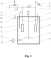
FIG. 2 is a schematic diagram of a continuous slurry-bed tank reactor with a function of feeding auxiliary materials. - The following further describes the present invention in detail with reference to the accompanying drawings and embodiments.
- As shown in
FIG. 1 , a continuous slurry-bed tank reactor comprises atank reactor body 8, anagitation system 7 and tubular separation membranes. - The
tank reactor body 8 is equipped with athermocouple 10 for measuring the reaction mixture temperature inside thetank reactor body 8, aliquid level gauge 5 for measuring the liquid level inside thetank reactor body 8, athird pressure gauge 12 for measuring the internal pressure of thetank reactor body 8, and agas flow controller 11 for measuring and controlling the gas flow rate into thetank reactor body 8. - The
agitation system 7 comprises an agitation motor, an agitation shaft and an agitation impeller. The agitation motor is set up at the center over thetank reactor body 8. A rotor of the agitation motor is vertically downwards installed. One end of the agitation shaft is fixedly connected with the rotor of the agitation motor, and the other end thereof penetrates through the upper cap of thetank reactor body 8 and extends to the bottom of thetank reactor body 8. The agitation impeller is installed at the bottom of the agitation shaft. - The tubular separation membranes comprise an A
tubular separation membrane 9 and a Btubular separation membrane 6, which are respectively vertically downwards located on the two sides of the agitation shaft. The Btubular separation membrane 6 and the Atubular separation membrane 9 are installed in the continuous tank reactor to achieve solid-liquid separation. Thetubular separation membranes way valve 3. The Atubular separation membrane 9 and the Btubular separation membrane 6 are respectively communicated with two longitudinally symmetrical ports of the four-way valve 3. The first opening and the second opening do not simultaneously feed or discharge liquid. Aliquid feed pump 13 is positioned at the first opening and connected with thefirst counterbalance valve 14 in parallel, and thefirst pressure gauge 15 is installed at thefirst counterbalance valve 14. Thesecond counterbalance valve 2 is installed at the second opening and used for adjusting the back pressure of the continuous slurry-bed tank reactor. The pressure of thesecond counterbalance valve 2 is set to a value higher than the sum of vapor pressures of system mediums by 0.2-1.0 MPa. The pressure of thesecond counterbalance valve 2 is set to the value lower than the designed pressure of the continuous slurry-bed tank reactor to avoid overpressure of the system when the system is abnormal and/or the reactants return before the feed pump. Thesecond pressure gauge 1 is installed in a pipeline joining thesecond counterbalance valve 2 and the upper port of the four-way valve 3. Thesecond pressure gauge 1 displays the back pressure of the continuous slurry-bed tank reactor, thethird pressure gauge 12 shows its internal pressure, and thefirst pressure gauge 15 displays its front pressure. - The four-
way valve 3 is used for switching the Atubular separation membrane 9 or the Btubular separation membrane 6 that are corresponding to the reaction mixture inlet and outlet so as to alternatively direct the reaction mixture flow into or out of the Atubular separation membrane 9 and the Btubular separation membrane 6, and thereby, to clean the catalyst adhered to the tubular separation membranes by the reverse reaction mixture flow and ensure that the Atubular separation membrane 9 and the Btubular separation membrane 6 are unblocked during the whole catalytic life of a catalyst. - The four-
way valve 3 generally runs in a timing switching mode. Nonetheless, when the internal pressure of the tank reactor body is increased to 0.8 MPa, the four-way valve 3 also switches the flow direction. - When the continuous slurry-bed tank reactor runs, the liquid level is maintained between a reasonable upper limit and a lower limit, and the top portion of the
tank reactor body 8 is filled with nitrogen gas. In the normal running process, reactants are fed into the continuous slurry-bed tank reactor at the preset flow rate. When the liquid level is relatively high, the filled nitrogen gas flow is speeded up for increasing the internal pressure of the continuous slurry-bed tank reactor. On the contrary, if the liquid level is relatively low, the filled nitrogen gas flow rate is lowered down. - When the liquid level of the continuous slurry-bed tank reactor is beyond the preset upper limit, the four-
way valve 3 switches the flow paths. - When the flow path switching time interval of the four-
way valve 3 is shorter than or equal to 2 hours, theliquid feed pump 13 stops operating, and the filling of the nitrogen gas is simultaneously stopped. After the permeability of the tubular separation membranes is confirmed to be declined, the continuous slurry-bed tank reactor is turned off, and the tubular separation membranes are replaced. - The liquid level of the reaction mixture in the tank reactor body is kept in an appropriate range by adapting the pressure of the nitrogen gas inside the tank reactor body to the feeding and discharging rates of the reaction mixture.
- Further, as is shown in
FIG. 2 , at least twoauxiliary material spargers 17 are installed at the low portion of the side wall of thetank reactor body 8, and each one extends into thetank reactor body 8, is set up at a different position in thetank reactor body 8, and communicated with one auxiliarymaterial feed pump 16 through a pipeline. - The claimed continuous slurry-bed tank reactor is configured to run with a method comprising the following steps:
- S1: adding a catalyst into the
tank reactor body 8, and filling nitrogen gas in thetank reactor body 8 by thegas flow controller 11 until all air in thetank reactor body 8 is replaced with the nitrogen gas, wherein thegas flow controller 11 measures and controls the flow rate of the nitrogen gas filled in thetank reactor body 8; - S2: feeding reactants into the
tank reactor body 8 sequentially through theliquid feed pump 13, the four-way valve 3 and the Atubular separation membrane 9; using a liquid level gauge to measure the liquid level of the fed reaction mixture and ensure that a distance between the liquid level of the reaction mixture and the top cap of thetank reactor body 8 is in the range of 5-80 cm; presetting the opening pressure of thefirst counterbalance valve 14 to a value lower than the designed pressure of thetank reactor body 8 by 0.3-0.5 MPa; - S3: when the liquid level of the reaction mixture is equal to the preset lower limit, stopping feeding the reactants; opening the heating system in the
tank reactor body 8 to raise the internal temperature of thetank reactor body 8 to the designed temperature; starting theagitation system 7; determining the internal pressure of thetank reactor body 8 at this moment to be the initial pressure, and setting the opening pressure of thesecond counterbalance valve 2 to a value higher than the initial pressure by 0.3-0.8 MPa; maintaining the temperature for 1-3 hours after the internal temperature of thetank reactor body 8 is increased to the preset temperature; turning on theliquid feed pump 13 again to start continuously feeding the reactants; - S4: setting the four-
way valve 3 to switch flow paths once every 4-8 hours for changing the direction of the reaction mixture flowing through the tubular separation membranes, wherein the four-way valve 3 switches the flow paths, and the switching time is concurrently reset when the internal pressure of thetank reactor body 8 is 0.8-1.0 MPa higher than the initially designed pressure; stopping feeding the reaction mixture when the flow path switching time interval is shorter than 2 hours due to an increase of the internal pressure of thetank reactor body 8. - Further, in step S2, at least two
auxiliary material spargers 17 are installed at the lower portion of the side wall of thetank reactor body 8. The auxiliarymaterial feed pump 16 adds reactants with poor miscibility in thetank reactor body 8 through theauxiliary material spargers 17. - Further, in step S3, when the liquid feed pump 13 starts continuously feeding the reactants, the
gas flow controller 11 is turned on. First, a small flow of nitrogen gas is filled. Then, the flow rate of the nitrogen gas is dynamically adjusted in terms of the changes of the liquid level. When the liquid level of the reaction mixture is close to the liquid level upper limit, the flow rate of the nitrogen gas is enlarged. On the contrary, if the liquid level of the reactants is approaching to the liquid level lower limit, the flow rate of the nitrogen gas is decreased. Notably, when the liquid level of the reaction mixture exceeds the liquid level upper limit, the four-way valve 3 is triggered to switch the flow paths. If the flow path switching time interval of the four-way valve 3 is shorter than 2 hours due to the increase of the internal pressure of the tank reactor body, the filling of nitrogen gas by thegas flow controller 11 would be stopped. - Further, the feeding amount of the
liquid feed pump 13 is determined to be 0.3-50 h-1 of the weight hourly space velocity on the basis of the reactant conversion and the product selectivity. When the flow path switching time interval of the four-way valve 3 is shortened due to the increase of the internal pressure or the change of the liquid level, the feeding amount of the reaction mixture is reduced until the catalytic performance of the catalyst or the permeability of the tubular separation membranes cannot meet the demands. - The following describes the current invention in detail by means of embodiments:
- A quantity of 2 kg MCM-22 molecular sieve catalyst with a Si/AI molar ratio of 100 is added in a 50 L tank reactor. Nitrogen gas is filled to replace air in the tank reactor. Liquid reactants of dimethoxymethane and 1 ,3,5-trioxane with a molar ratio of 2:1 are pumped into the tank reactor by a
liquid feed pump 13 up to the distance between the liquid level and the top cap of thetank reactor body 8 of 15 cm. Then, the heating system of the tank reactor is started to raise the temperature inside thetank reactor body 8 to 50 °C. Simultaneously, theagitation system 7 is initiated. After two hours, theliquid feed pump 13 restarts to continuously feed the reaction mixture. The opening pressure ofcounterbalance valve 2 is set to 0.5 MPa; the flow rate of theliquid feed pump 13 is set to 30 l/h; the flow path switching time interval of the four-way valve 3 is set to six hours; the starting pressure ofcounterbalance valve 14 is set to 1.2 MPa, and the initial flow rate of thegas flow controller 11 is set to 5 sccm (1/12 ml/s) that is later altered according to the changes of the liquid level in the following way. The flow rate of thegas flow controller 11 is increased with the elevation of the liquid level, but is decreased with the reduction of the liquid level. In the present embodiment, to maintain normal operation, the liquid level needs to intermediate between the upper limit of 5 cm and the lower limit of 15 cm distant from the top cap of thetank reactor body 8. - The tank reactor continuously and stably runs. In the later process, the conversion of the reactants lowers down due to the deactivation of the catalyst. Thereafter, the reaction is stopped.
- A quantity of 2 kg MCM-22 molecular sieve catalyst with a Si/AI molar ratio of 200 is added in a 50 I tank reactor. Nitrogen gas is filled to replace air in the tank reactor. Dimethoxymethane and 1,3,5-trioxane liquid mixture with a molar ratio of 2.5:1 are pumped into the tank reactor by the
liquid feed pump 13 up to the distance between the liquid level and the top cap of thetank reactor body 8 of 15 cm. After that, the heating system of the tank reactor is opened to elevate the temperature of the tank reactor to 65 °C. Simultaneously, theagitation system 7 is started. After one hour, theliquid feed pump 13 restarts to continuously feed the reactants. The opening pressure ofcounterbalance valve 2 is set to 0.8 MPa; the flow rate of theliquid feed pump 13 is set to 50 l/h; the flow path switching time interval of the four-way valve 3 is set to 4 hours; the opening pressure ofcounterbalance valve 14 is set to 1.2 MPa, and the initial flow rate of thegas flow controller 11 is set to 5 sccm that is adjusted in terms of the liquid level in the reaction process in the following way. The flow rate of thegas flow controller 11 is increased with the elevation of the liquid level, and is decreased with the decline of the liquid level. In the present embodiment, to maintain normal operation, the upper limit and the lower limit of the liquid level are set to 5 and 15 cm from the top cap of thetank reactor body 8 respectively. - The tank reactor continuously and stably runs for more than 500 hours. In the later process, the conversion of the raw materials lowers down, but the selectivity to product is still high.
- A quantity of 2 kg MCM-22 molecular sieve catalyst with a Si/AI molar ratio of 50 is added in a 50 I tank reactor. Nitrogen gas is filled to replace air in the tank reactor. Dimethoxymethane and 1,3,5-trioxane liquid mixture with a molar ratio of 2.5:1 are pumped into the tank reactor by a
liquid feed pump 13 until the distance between the liquid level and the top cap of thetank reactor body 8 reaches 15 cm. Then, the heating system of the tank reactor is started to raise the temperature of the tank reactor to 35 °C. Simultaneously, theagitation system 7 is initiated. After 3 hours, theliquid feed pump 13 restarts to continuously feed the reactants. The opening pressure of thecounterbalance valve 2 is set to 0.3 MPa; the flow rate of theliquid feed pump 13 is set to 50 l/h; the flow path switching time interval of the four-way valve 3 is set to eight hours; the opening pressure of thecounterbalance valve 14 is set to 1.2 MPa, the initial flow rate of thegas flow controller 11 is set to 5 sccm (1/12 ml/s) that is adjusted according to the changes of the liquid level in the reaction process in the following way. The flow rate of thegas flow controller 11 is increased with the elevation of the liquid level, and is decreased with the decline of the liquid level. In the present embodiment, to maintain normal operation, the upper limit and the lower limit of the liquid level are set to 5 and 15 cm from the top cap of thetank reactor body 8 respectively. - After the tank reactor continuously runs for more than 100 hours, the conversion of the reactants is slightly decreased although the selectivity to products is still high.
- A quantity of 2 kg MCM-22 molecular sieve catalyst with a Si/AI molar ratio of 50 is added in a 50 I tank reactor. Nitrogen gas is filled to replace air in the tank reactor. Liquid reactants of dimethoxymethane and 1 ,3,5-trioxane with a molar ratio of 2.5:1 are pumped into the tank reactor by a
liquid feed pump 13 until the distance between the liquid level and the top cap of thetank reactor body 8 reaches 15 cm. Afterwards, the heating system of the tank reactor is started to raise the temperature of the tank reactor to 35 °C. Simultaneously, theagitation system 7 is initiated. After 3 hours, theliquid feed pump 13 restarts to continuously feed the reactants. The opening pressure ofcounterbalance valve 2 is set to 0.3 MPa; the flow rate of theliquid feed pump 13 is set to 50 l/h; the flow path switching time interval of the four-way valve 3 is set to eight hours; the opening pressure ofcounterbalance valve 14 is set to 1.2 MPa, and the initial flow rate of agas flow controller 11 is set to 5 sccm (1/12 ml/s) that is adjusted according to the changes of the liquid level in the reaction process in the following way. The flow rate of thegas flow controller 11 is enlarged with the elevation of the liquid level, and is decreased with the reduction of the liquid level. In the present embodiment, to maintain normal operation, the upper limit and the lower limit of the liquid level are set to 5 and 15 cm from the top cap of thetank reactor body 8. - The tank reactor continuously and stably runs. In the later process, the conversion of the reactants is slightly decreased due to the deactivation of the catalyst, thus the reaction is stopped.
- A quantity of 3 kg titanium silicalite molecular sieve catalyst is added to a 50 I tank reactor. Nitrogen gas is filled to replace air in the tank reactor. Benzene is pumped into the tank reactor by the
liquid feed pump 13 until the distance between the liquid level and the top cap of thetank reactor body 8 reaches 15 cm. Afterwards, the heating system of the tank reactor is opened to raise the temperature of the tank reactor to 85 °C. Simultaneously, theagitation system 7 is started. After three hours, theliquid feed pump 13 restarts to continuously feed the reactants. Hydrogen peroxide is pumped through the auxiliarymaterial feed pump 16, and fed into the tank reactor by fourauxiliary material spargers 17 at a rate of 5 l/h in different positions. The auxiliarymaterial feed pump 16 and theliquid feed pump 13 are controlled to simultaneously start and stop. The opening pressure of thecounterbalance valve 2 is set to 0.6 MPa; the flow rate of theliquid feed pump 13 is set to 20 l/h; the flow path switching time interval of the four-way valve 3 is set to four hours; the opening pressure of thecounterbalance valve 14 is set to 1.8 MPa, the initial flow rate of thegas flow controller 11 is set to 5 sccm (1/12 ml/s) that is adjusted in terms of the changes of the liquid level in the reaction process in the following way. The flow rate of thegas flow controller 11 is increased with the elevation of the liquid level, and is decreased with the decline of the liquid level. In the present embodiment, to maintain normal operation, the upper and the lower limits of the liquid level are set to 10 and 20 cm from the top cap of thetank reactor body 8 respectively. When the distance between the liquid level and the top cap of thetank reactor body 8 is shorter than 10 cm, the auxiliarymaterial feed pump 16 and theauxiliary material spargers 17 are stopped. - A quantity of 3 kg titanium silicalite molecular sieve catalyst is added in a 50 I tank reactor. Nitrogen gas is filled to replace air in the tank reactor. Cyclohexanone is pumped into the tank reactor by a
liquid feed pump 13 up to the distance between the liquid level and the top cap of thetank reactor body 8 of 15 cm. Afterwards, the heating system of the tank reactor is started to raise the temperature of the tank reactor to 75 °C. Simultaneously, theagitation system 7 is initiated. After two hours, theliquid feed pump 13 restarts to continuously feed the reactants. Hydrogen peroxide is pumped through the auxiliarymaterial feed pump 16, and fed into the tank reactor by fourauxiliary material spargers 17 at a rate of 10 l/h in different positions. The auxiliarymaterial feed pump 16 and theliquid feed pump 13 are controlled to simultaneously start and stop. The opening pressure of thecounterbalance valve 2 is set to 0.6 MPa; the flow rate of theliquid feed pump 13 is set to 30 l/h; the flow path switching time interval of the four-way valve 3 is set to four hours; the opening pressure of thecounterbalance valve 14 is set to 1.6 MPa, and the initial flow rate of thegas flow controller 11 is set to 5 sccm (1/12 ml/s) that is adjusted according to the changes of the liquid level in the following way. The flow rate of thegas flow controller 11 is increased with the elevation of the liquid level, and is decreased with the reduction of the liquid level. In the present embodiment, to maintain normal operation, the upper and the lower limits of the liquid level is 8 and 20 cm away from the top of thetank reactor body 8, respectively. When the distance between the liquid level and the top cap of thetank reactor body 8 is less than 8 cm, the auxiliarymaterial feed pump 16 and theauxiliary material spargers 17 are stopped. - The above merely describes specific embodiments of the present invention, but the protection scope of the present invention is not limited thereto. A person skilled in the art can easily conceive modifications or replacements within the technical scope of the present invention, which is defined by the claims.
-
- 1
- second pressure gauge,
- 2
- second counterbalance valve,
- 3
- four-way valve,
- 4
- liquid level,
- 5
- liquid level gauge,
- 6
- B tubular separation membrane,
- 7
- agitation system,
- 8
- tank reactor body,
- 9
- A tubular separation membrane,
- 10
- thermocouple,
- 11
- gas flow controller,
- 12
- third pressure gauge,
- 13
- liquid feed pump,
- 14
- first counterbalance valve,
- 15
- first pressure gauge,
- 16
- auxiliary material feed pump,
- 17
- auxiliary material sparger.
Claims (3)
- A continuous slurry-bed tank reactor, comprising a tank reactor body (8), an agitation system (7) and tubular separation membranes, whereinthe tank reactor body (8) is respectively equipped with a thermocouple (10) for measuring the internal temperature of the tank reactor body (8), a liquid level gauge (5) for measuring a liquid level inside the tank reactor body (8), a third pressure gauge (12) for measuring an internal pressure of the tank reactor body (8), and a gas flow controller (11) for measuring and controlling a gas flow rate into the tank reactor body (8);the agitation system (7) comprises an agitation motor, an agitation shaft and an agitation impeller;the agitation motor is set up at the center over the tank reactor body (8); a rotor of the agitation motor is vertically downwards installed;one end of the agitation shaft is fixedly connected with the rotor of the agitation motor, and the other end thereof penetrates through the upper cap of the tank reactor body (8) and extends to the bottom of the tank reactor body (8); the agitation impeller is located at the bottom of the agitation shaft;the tubular separation membranes comprise an A tubular separation membrane (9) and an B tubular separation membrane (6), which are respectively vertically downwards positioned on two sides of the agitation shaft;a first opening and a second opening of the continuous slurry-bed tank reactor are respectively communicated with two transversely symmetrical ports of a four-way valve (3);the A tubular separation membrane (9) and the B tubular separation membrane (6) are respectively communicated with two longitudinally symmetrical ports of the four-way valve (3); the first opening and the second opening do not simultaneously feed or discharge liquid; characterized in thata liquid feed pump (13) is set up at the first opening and connected with a first counterbalance valve (14) in parallel with a first pressure gauge (15) installed at the first counterbalance valve (14);a second counterbalance valve (2) is installed at the second opening and a second pressure gauge (1) is installed in a pipeline communicated with the second counterbalance valve (2) and an upper port of the four-way valve (3);the four-way valve (3) is configured for switching flow paths for changing directions of liquid flowing through the A tubular separation membrane (9) or the B tubular separation membrane (6) so as to alternatively direct a reaction mixture flow in or out the A tubular separation membrane (9) and the B tubular separation membrane (6) by generally running the four-way valve (3) in a timing switching mode to clean the catalyst adhered to the A tubular and the B tubular separation membranes (9, 6) by reverse reaction mixture flow, and also switching flow direction when the internal pressure of the tank reactor body (8) is increased to 0.8 MPa;the slurry-bed tank reactor is so configured that a nanomaterial-based catalyst and reactants can be directly separated, wherein both the A tubular separation membrane (9) and the B tubular separation membrane (6) utilize stainless steel tubes fabricated in a powder metallurgy manner as a substrate, and the permeabilities of the A tubular separation membrane (9) and the B tubular separation membrane (6) are finely adjusted through chemical vapor deposition thereby meeting double demands of permeability and effective separation of solid catalysts with different particle sizes and liquid reactants, whereinthe slurry-bed tank reactor is configured to run the following steps:S1: adding a catalyst into the tank reactor body, and filling nitrogen gas in the tank reactor body by the gas flow controller until all air in the tank reactor body is replaced with nitrogen gas, wherein the gas flow controller measures and controls the flow rate of the nitrogen gas filled in the tank reactor body;S2: feeding reactants into the tank reactor body sequentially through the liquid feed pump, the four-way valve and the A tubular separation membrane; using a liquid level gauge to measure the liquid level of the fed reactants and ensure that a distance between the liquid level of the reactants and the top cap of the tank reactor body is in the range of 5-80 cm; presetting the opening pressure of the first counterbalance valve to a value lower than the designed pressure of the tank reactor body by 0.3-0.5 MPa;S3: when the liquid level of the reactants reaches the preset lower limit, stopping feeding the reactants; opening a heating system in the tank reactor body to raise the internal temperature of the tank reactor body to the preset temperature; simultaneously opening the agitation system; determining the internal pressure of the tank reactor body at this moment as the initial pressure, and setting the opening pressure of the second counterbalance valve to be 0.3-0.8 MPa higher than the initial pressure; maintaining the temperature for 1-3 hours after the internal temperature of the tank reactor body is elevated to the preset temperature; turning on the liquid feed pump again to start continuously feeding the reactants;S4: setting the four-way valve to switch flow paths once every 4-8 hours for altering the directions of reaction mixture flowing through the tubular separation membranes; resetting the four-way valve to switch the flow paths and recalculating the flow path switching time when the internal pressure of the tank reactor body is higher than the initial pressure by 0.8-1.0 MPa; stopping feeding the reactants when the time interval for switching the flow path is shorter than two hours because of the increase in the internal pressure of the tank reactor body.
- The continuous slurry-bed tank reactor according to claim 1, wherein at least two auxiliary material spargers (17) are installed at the lower portion of a side wall of the tank reactor body (8); and each one extends into the tank reactor body (8) and is connected with an auxiliary material feed pump (16) through a pipeline.
- The continuous slurry-bed tank reactor according to claim 1, wherein the four-way valve (3) running in the time switching mode, has a further flow switching mode due to liquid level when the liquid level of the reaction mixture exceeds a liquid level upper limit of the tank reactor body (8).
Applications Claiming Priority (1)
| Application Number | Priority Date | Filing Date | Title |
|---|---|---|---|
| CN201910356734.6A CN110180470B (en) | 2019-04-29 | 2019-04-29 | Kettle type continuous slurry bed reactor and use method thereof |
Publications (2)
| Publication Number | Publication Date |
|---|---|
| EP3733275A1 EP3733275A1 (en) | 2020-11-04 |
| EP3733275B1 true EP3733275B1 (en) | 2024-03-13 |
Family
ID=67715264
Family Applications (1)
| Application Number | Title | Priority Date | Filing Date |
|---|---|---|---|
| EP20165628.7A Active EP3733275B1 (en) | 2019-04-29 | 2020-03-25 | Continuous slurry-bed tank reactor and method of using same |
Country Status (4)
| Country | Link |
|---|---|
| US (1) | US11338263B2 (en) |
| EP (1) | EP3733275B1 (en) |
| CN (1) | CN110180470B (en) |
| DK (1) | DK3733275T3 (en) |
Families Citing this family (7)
| Publication number | Priority date | Publication date | Assignee | Title |
|---|---|---|---|---|
| CN112959539B (en) * | 2021-02-05 | 2023-01-17 | 西安近代化学研究所 | Continuous dewatering mixed pouring device and process for high-viscosity filler-containing heat-insulating coating |
| CN113289523A (en) * | 2021-06-16 | 2021-08-24 | 上海富昶环保科技有限公司 | Negative pressure powder feeding dustless double-power pulping kettle |
| CN113828255A (en) * | 2021-10-22 | 2021-12-24 | 上海华谊(集团)公司 | Gas-liquid-solid three-phase catalytic oxidation reaction kettle and application thereof |
| CN114653328A (en) * | 2022-03-25 | 2022-06-24 | 中国科学院过程工程研究所 | Built-in membrane stirring reactor |
| CN114713035B (en) * | 2022-03-31 | 2023-05-05 | 中国科学院过程工程研究所 | Continuous filtration process monitoring device and method for filtration membrane |
| CN114917844A (en) * | 2022-04-22 | 2022-08-19 | 北京世纪森朗实验仪器有限公司 | Gas-liquid-solid three-phase steady-state continuous reaction system |
| CN119386779A (en) * | 2025-01-02 | 2025-02-07 | 浙江圣安化工股份有限公司 | A reaction device for continuous alcohol-ketone condensation reaction |
Citations (1)
| Publication number | Priority date | Publication date | Assignee | Title |
|---|---|---|---|---|
| WO2012011142A1 (en) * | 2010-07-22 | 2012-01-26 | Fabio Cipri | Membranes and process for the realization thereof |
Family Cites Families (12)
| Publication number | Priority date | Publication date | Assignee | Title |
|---|---|---|---|---|
| SU1473833A1 (en) * | 1987-09-09 | 1989-04-23 | Предприятие П/Я А-7971 | Contact apparatus for oxidizing sulphur dioxide into sulphur trioxide |
| US7160344B2 (en) * | 2002-12-18 | 2007-01-09 | Council Of Scientific And Industrial Research | Process for the continuous production of carbon monoxide-free hydrogen from methane or methane-rich hydrocarbons |
| DE10353391A1 (en) * | 2003-11-15 | 2005-06-16 | Oxeno Olefinchemie Gmbh | Apparatus for carrying out liquid reactions with fine-grained solid catalysts and method for its use |
| US7569196B2 (en) * | 2004-09-16 | 2009-08-04 | Oxeno Olefinchemie Gmbh | Device for carrying out liquid reactions with fine-grained solid catalysts and method for the use thereof |
| US20100084350A1 (en) * | 2008-10-06 | 2010-04-08 | Jing Liu | Systems and Methods for Continuous Multiphase Reaction and Separation |
| CN103007857A (en) * | 2012-12-06 | 2013-04-03 | 新岸诺亚(北京)催化科技有限公司 | Industrial water-free oxygen-free production apparatus |
| CN103232326A (en) * | 2013-04-28 | 2013-08-07 | 南京工业大学 | Continuous production process for preparing phenol by benzene hydroxylation |
| CN104084102B (en) * | 2014-07-08 | 2016-01-20 | 山东东昌精细化工科技有限公司 | A kind of ring manganese reaction production technology realizing the method for anhydrous and oxygen-free operation and the methyl cyclopentadienyl manganese of application the method |
| CN104926627A (en) * | 2014-12-26 | 2015-09-23 | 北京东方红升新能源应用技术研究院有限公司 | Continuous reaction device for synthetizing polymethoxy dimethyl ether |
| CN106008128B (en) * | 2016-05-25 | 2018-06-26 | 上海交通大学 | The reaction-regeneration system and method for a kind of preparing propylene from methanol |
| CN106220481B (en) * | 2016-07-27 | 2018-11-23 | 中国科学院山西煤炭化学研究所 | A kind of technique of continuous production polyoxymethylene dimethyl ether |
| CN209952810U (en) * | 2019-04-29 | 2020-01-17 | 中国科学院山西煤炭化学研究所 | Kettle type continuous slurry bed reactor |
-
2019
- 2019-04-29 CN CN201910356734.6A patent/CN110180470B/en active Active
-
2020
- 2020-03-25 EP EP20165628.7A patent/EP3733275B1/en active Active
- 2020-03-25 DK DK20165628.7T patent/DK3733275T3/en active
- 2020-04-15 US US16/849,396 patent/US11338263B2/en active Active
Patent Citations (1)
| Publication number | Priority date | Publication date | Assignee | Title |
|---|---|---|---|---|
| WO2012011142A1 (en) * | 2010-07-22 | 2012-01-26 | Fabio Cipri | Membranes and process for the realization thereof |
Also Published As
| Publication number | Publication date |
|---|---|
| CN110180470B (en) | 2024-01-26 |
| US20200338516A1 (en) | 2020-10-29 |
| DK3733275T3 (en) | 2024-05-13 |
| EP3733275A1 (en) | 2020-11-04 |
| CN110180470A (en) | 2019-08-30 |
| US11338263B2 (en) | 2022-05-24 |
Similar Documents
| Publication | Publication Date | Title |
|---|---|---|
| EP3733275A1 (en) | Continuous slurry-bed tank reactor and method of using same | |
| US11084772B2 (en) | Process for continuously producing polyoxymethylene dimethyl ethers at low temperature | |
| CN101850225A (en) | A kind of benzene selective hydrogenation device | |
| CN111718279B (en) | Method and device for continuously producing sartanbiphenyl | |
| CN111072598B (en) | Process for producing epichlorohydrin by direct oxidation of titanium-silicon molecular sieve catalyst | |
| CN108821971A (en) | A kind of cyclopentyl acetate synthesis technology | |
| CN105561894A (en) | Self-organization flow division type control method and device for preparing sorbitol through integral reaction and separation | |
| CN106278836A (en) | Intermediate concentration formaldehyde and the apparatus and method of methylal synthesis polymethoxy dimethyl ether | |
| CN209952810U (en) | Kettle type continuous slurry bed reactor | |
| CN103232326A (en) | Continuous production process for preparing phenol by benzene hydroxylation | |
| US20140336407A1 (en) | Integrated system technique for coupling fixed bed and jet fluidized bed to separator unit | |
| CN101574636B (en) | Tubular membrane reactor | |
| CN114105735A (en) | Preparation method and production device of Guerbet alcohol ether | |
| EP3870357B1 (en) | Membrane-based process for butanols production from mixed butenes | |
| CN221536620U (en) | Etherification reactor and reaction system for etherification separation of isoolefins | |
| CN114736122B (en) | Reaction circulation rectification process method for producing methyl ethyl carbonate and diethyl ester | |
| CN108017540A (en) | The technique of one-step synthesis methyl ethyl carbonate co-production 1,2- propane diols | |
| US6982235B2 (en) | Method for regenerating solid catalyst | |
| CN112023852A (en) | Production device for preparing cyclohexene through partial hydrogenation of benzene | |
| CN109851792A (en) | A kind of preparation process of solid acid catalysis synthesis polysiloxanes | |
| CN107935845A (en) | A kind of method that reactive distillation prepares cyclohexyl acetate | |
| CN114515549A (en) | Pre-hydrogenation reaction system, pre-hydrogenation reaction method and application | |
| CN119281233B (en) | Benzene selective hydrogenation reactor and benzene selective hydrogenation reaction method | |
| CN218359155U (en) | Process system for removing hydrogen peroxide and aldehyde compounds in HPPO system by two-step method | |
| CN115304470B (en) | A method for catalytic oxidation of glucose to produce formic acid in a microchannel reactor |
Legal Events
| Date | Code | Title | Description |
|---|---|---|---|
| PUAI | Public reference made under article 153(3) epc to a published international application that has entered the european phase |
Free format text: ORIGINAL CODE: 0009012 |
|
| STAA | Information on the status of an ep patent application or granted ep patent |
Free format text: STATUS: THE APPLICATION HAS BEEN PUBLISHED |
|
| AK | Designated contracting states |
Kind code of ref document: A1 Designated state(s): AL AT BE BG CH CY CZ DE DK EE ES FI FR GB GR HR HU IE IS IT LI LT LU LV MC MK MT NL NO PL PT RO RS SE SI SK SM TR |
|
| AX | Request for extension of the european patent |
Extension state: BA ME |
|
| STAA | Information on the status of an ep patent application or granted ep patent |
Free format text: STATUS: REQUEST FOR EXAMINATION WAS MADE |
|
| 17P | Request for examination filed |
Effective date: 20210504 |
|
| RBV | Designated contracting states (corrected) |
Designated state(s): AL AT BE BG CH CY CZ DE DK EE ES FI FR GB GR HR HU IE IS IT LI LT LU LV MC MK MT NL NO PL PT RO RS SE SI SK SM TR |
|
| STAA | Information on the status of an ep patent application or granted ep patent |
Free format text: STATUS: EXAMINATION IS IN PROGRESS |
|
| 17Q | First examination report despatched |
Effective date: 20210721 |
|
| GRAP | Despatch of communication of intention to grant a patent |
Free format text: ORIGINAL CODE: EPIDOSNIGR1 |
|
| STAA | Information on the status of an ep patent application or granted ep patent |
Free format text: STATUS: GRANT OF PATENT IS INTENDED |
|
| INTG | Intention to grant announced |
Effective date: 20231027 |
|
| GRAS | Grant fee paid |
Free format text: ORIGINAL CODE: EPIDOSNIGR3 |
|
| GRAA | (expected) grant |
Free format text: ORIGINAL CODE: 0009210 |
|
| STAA | Information on the status of an ep patent application or granted ep patent |
Free format text: STATUS: THE PATENT HAS BEEN GRANTED |
|
| AK | Designated contracting states |
Kind code of ref document: B1 Designated state(s): AL AT BE BG CH CY CZ DE DK EE ES FI FR GB GR HR HU IE IS IT LI LT LU LV MC MK MT NL NO PL PT RO RS SE SI SK SM TR |
|
| REG | Reference to a national code |
Ref country code: GB Ref legal event code: FG4D |
|
| REG | Reference to a national code |
Ref country code: CH Ref legal event code: EP |
|
| REG | Reference to a national code |
Ref country code: DE Ref legal event code: R096 Ref document number: 602020027047 Country of ref document: DE |
|
| REG | Reference to a national code |
Ref country code: IE Ref legal event code: FG4D |
|
| REG | Reference to a national code |
Ref country code: DK Ref legal event code: T3 Effective date: 20240508 |
|
| P01 | Opt-out of the competence of the unified patent court (upc) registered |
Effective date: 20240419 |
|
| PG25 | Lapsed in a contracting state [announced via postgrant information from national office to epo] |
Ref country code: LT Free format text: LAPSE BECAUSE OF FAILURE TO SUBMIT A TRANSLATION OF THE DESCRIPTION OR TO PAY THE FEE WITHIN THE PRESCRIBED TIME-LIMIT Effective date: 20240313 |
|
| REG | Reference to a national code |
Ref country code: LT Ref legal event code: MG9D |
|
| PG25 | Lapsed in a contracting state [announced via postgrant information from national office to epo] |
Ref country code: GR Free format text: LAPSE BECAUSE OF FAILURE TO SUBMIT A TRANSLATION OF THE DESCRIPTION OR TO PAY THE FEE WITHIN THE PRESCRIBED TIME-LIMIT Effective date: 20240614 |
|
| REG | Reference to a national code |
Ref country code: NL Ref legal event code: MP Effective date: 20240313 |
|
| PG25 | Lapsed in a contracting state [announced via postgrant information from national office to epo] |
Ref country code: HR Free format text: LAPSE BECAUSE OF FAILURE TO SUBMIT A TRANSLATION OF THE DESCRIPTION OR TO PAY THE FEE WITHIN THE PRESCRIBED TIME-LIMIT Effective date: 20240313 Ref country code: RS Free format text: LAPSE BECAUSE OF FAILURE TO SUBMIT A TRANSLATION OF THE DESCRIPTION OR TO PAY THE FEE WITHIN THE PRESCRIBED TIME-LIMIT Effective date: 20240613 |
|
| PG25 | Lapsed in a contracting state [announced via postgrant information from national office to epo] |
Ref country code: ES Free format text: LAPSE BECAUSE OF FAILURE TO SUBMIT A TRANSLATION OF THE DESCRIPTION OR TO PAY THE FEE WITHIN THE PRESCRIBED TIME-LIMIT Effective date: 20240313 |
|
| PG25 | Lapsed in a contracting state [announced via postgrant information from national office to epo] |
Ref country code: RS Free format text: LAPSE BECAUSE OF FAILURE TO SUBMIT A TRANSLATION OF THE DESCRIPTION OR TO PAY THE FEE WITHIN THE PRESCRIBED TIME-LIMIT Effective date: 20240613 Ref country code: NO Free format text: LAPSE BECAUSE OF FAILURE TO SUBMIT A TRANSLATION OF THE DESCRIPTION OR TO PAY THE FEE WITHIN THE PRESCRIBED TIME-LIMIT Effective date: 20240613 Ref country code: LT Free format text: LAPSE BECAUSE OF FAILURE TO SUBMIT A TRANSLATION OF THE DESCRIPTION OR TO PAY THE FEE WITHIN THE PRESCRIBED TIME-LIMIT Effective date: 20240313 Ref country code: HR Free format text: LAPSE BECAUSE OF FAILURE TO SUBMIT A TRANSLATION OF THE DESCRIPTION OR TO PAY THE FEE WITHIN THE PRESCRIBED TIME-LIMIT Effective date: 20240313 Ref country code: GR Free format text: LAPSE BECAUSE OF FAILURE TO SUBMIT A TRANSLATION OF THE DESCRIPTION OR TO PAY THE FEE WITHIN THE PRESCRIBED TIME-LIMIT Effective date: 20240614 Ref country code: FI Free format text: LAPSE BECAUSE OF FAILURE TO SUBMIT A TRANSLATION OF THE DESCRIPTION OR TO PAY THE FEE WITHIN THE PRESCRIBED TIME-LIMIT Effective date: 20240313 Ref country code: ES Free format text: LAPSE BECAUSE OF FAILURE TO SUBMIT A TRANSLATION OF THE DESCRIPTION OR TO PAY THE FEE WITHIN THE PRESCRIBED TIME-LIMIT Effective date: 20240313 Ref country code: BG Free format text: LAPSE BECAUSE OF FAILURE TO SUBMIT A TRANSLATION OF THE DESCRIPTION OR TO PAY THE FEE WITHIN THE PRESCRIBED TIME-LIMIT Effective date: 20240313 |
|
| REG | Reference to a national code |
Ref country code: AT Ref legal event code: MK05 Ref document number: 1665237 Country of ref document: AT Kind code of ref document: T Effective date: 20240313 |
|
| PG25 | Lapsed in a contracting state [announced via postgrant information from national office to epo] |
Ref country code: SE Free format text: LAPSE BECAUSE OF FAILURE TO SUBMIT A TRANSLATION OF THE DESCRIPTION OR TO PAY THE FEE WITHIN THE PRESCRIBED TIME-LIMIT Effective date: 20240313 Ref country code: LV Free format text: LAPSE BECAUSE OF FAILURE TO SUBMIT A TRANSLATION OF THE DESCRIPTION OR TO PAY THE FEE WITHIN THE PRESCRIBED TIME-LIMIT Effective date: 20240313 |
|
| PG25 | Lapsed in a contracting state [announced via postgrant information from national office to epo] |
Ref country code: NL Free format text: LAPSE BECAUSE OF FAILURE TO SUBMIT A TRANSLATION OF THE DESCRIPTION OR TO PAY THE FEE WITHIN THE PRESCRIBED TIME-LIMIT Effective date: 20240313 |
|
| PG25 | Lapsed in a contracting state [announced via postgrant information from national office to epo] |
Ref country code: NL Free format text: LAPSE BECAUSE OF FAILURE TO SUBMIT A TRANSLATION OF THE DESCRIPTION OR TO PAY THE FEE WITHIN THE PRESCRIBED TIME-LIMIT Effective date: 20240313 |
|
| PG25 | Lapsed in a contracting state [announced via postgrant information from national office to epo] |
Ref country code: IS Free format text: LAPSE BECAUSE OF FAILURE TO SUBMIT A TRANSLATION OF THE DESCRIPTION OR TO PAY THE FEE WITHIN THE PRESCRIBED TIME-LIMIT Effective date: 20240713 |
|
| PG25 | Lapsed in a contracting state [announced via postgrant information from national office to epo] |
Ref country code: PT Free format text: LAPSE BECAUSE OF FAILURE TO SUBMIT A TRANSLATION OF THE DESCRIPTION OR TO PAY THE FEE WITHIN THE PRESCRIBED TIME-LIMIT Effective date: 20240715 Ref country code: SM Free format text: LAPSE BECAUSE OF FAILURE TO SUBMIT A TRANSLATION OF THE DESCRIPTION OR TO PAY THE FEE WITHIN THE PRESCRIBED TIME-LIMIT Effective date: 20240313 |
|
| PG25 | Lapsed in a contracting state [announced via postgrant information from national office to epo] |
Ref country code: CZ Free format text: LAPSE BECAUSE OF FAILURE TO SUBMIT A TRANSLATION OF THE DESCRIPTION OR TO PAY THE FEE WITHIN THE PRESCRIBED TIME-LIMIT Effective date: 20240313 Ref country code: EE Free format text: LAPSE BECAUSE OF FAILURE TO SUBMIT A TRANSLATION OF THE DESCRIPTION OR TO PAY THE FEE WITHIN THE PRESCRIBED TIME-LIMIT Effective date: 20240313 |
|
| PG25 | Lapsed in a contracting state [announced via postgrant information from national office to epo] |
Ref country code: AT Free format text: LAPSE BECAUSE OF FAILURE TO SUBMIT A TRANSLATION OF THE DESCRIPTION OR TO PAY THE FEE WITHIN THE PRESCRIBED TIME-LIMIT Effective date: 20240313 |
|
| PG25 | Lapsed in a contracting state [announced via postgrant information from national office to epo] |
Ref country code: PL Free format text: LAPSE BECAUSE OF FAILURE TO SUBMIT A TRANSLATION OF THE DESCRIPTION OR TO PAY THE FEE WITHIN THE PRESCRIBED TIME-LIMIT Effective date: 20240313 |
|
| PG25 | Lapsed in a contracting state [announced via postgrant information from national office to epo] |
Ref country code: SK Free format text: LAPSE BECAUSE OF FAILURE TO SUBMIT A TRANSLATION OF THE DESCRIPTION OR TO PAY THE FEE WITHIN THE PRESCRIBED TIME-LIMIT Effective date: 20240313 |
|
| PG25 | Lapsed in a contracting state [announced via postgrant information from national office to epo] |
Ref country code: SM Free format text: LAPSE BECAUSE OF FAILURE TO SUBMIT A TRANSLATION OF THE DESCRIPTION OR TO PAY THE FEE WITHIN THE PRESCRIBED TIME-LIMIT Effective date: 20240313 Ref country code: SK Free format text: LAPSE BECAUSE OF FAILURE TO SUBMIT A TRANSLATION OF THE DESCRIPTION OR TO PAY THE FEE WITHIN THE PRESCRIBED TIME-LIMIT Effective date: 20240313 Ref country code: RO Free format text: LAPSE BECAUSE OF FAILURE TO SUBMIT A TRANSLATION OF THE DESCRIPTION OR TO PAY THE FEE WITHIN THE PRESCRIBED TIME-LIMIT Effective date: 20240313 Ref country code: PT Free format text: LAPSE BECAUSE OF FAILURE TO SUBMIT A TRANSLATION OF THE DESCRIPTION OR TO PAY THE FEE WITHIN THE PRESCRIBED TIME-LIMIT Effective date: 20240715 Ref country code: PL Free format text: LAPSE BECAUSE OF FAILURE TO SUBMIT A TRANSLATION OF THE DESCRIPTION OR TO PAY THE FEE WITHIN THE PRESCRIBED TIME-LIMIT Effective date: 20240313 Ref country code: IS Free format text: LAPSE BECAUSE OF FAILURE TO SUBMIT A TRANSLATION OF THE DESCRIPTION OR TO PAY THE FEE WITHIN THE PRESCRIBED TIME-LIMIT Effective date: 20240713 Ref country code: EE Free format text: LAPSE BECAUSE OF FAILURE TO SUBMIT A TRANSLATION OF THE DESCRIPTION OR TO PAY THE FEE WITHIN THE PRESCRIBED TIME-LIMIT Effective date: 20240313 Ref country code: CZ Free format text: LAPSE BECAUSE OF FAILURE TO SUBMIT A TRANSLATION OF THE DESCRIPTION OR TO PAY THE FEE WITHIN THE PRESCRIBED TIME-LIMIT Effective date: 20240313 Ref country code: AT Free format text: LAPSE BECAUSE OF FAILURE TO SUBMIT A TRANSLATION OF THE DESCRIPTION OR TO PAY THE FEE WITHIN THE PRESCRIBED TIME-LIMIT Effective date: 20240313 |
|
| REG | Reference to a national code |
Ref country code: CH Ref legal event code: PL |
|
| PG25 | Lapsed in a contracting state [announced via postgrant information from national office to epo] |
Ref country code: LU Free format text: LAPSE BECAUSE OF NON-PAYMENT OF DUE FEES Effective date: 20240325 |
|
| PG25 | Lapsed in a contracting state [announced via postgrant information from national office to epo] |
Ref country code: LU Free format text: LAPSE BECAUSE OF NON-PAYMENT OF DUE FEES Effective date: 20240325 |
|
| PG25 | Lapsed in a contracting state [announced via postgrant information from national office to epo] |
Ref country code: IT Free format text: LAPSE BECAUSE OF FAILURE TO SUBMIT A TRANSLATION OF THE DESCRIPTION OR TO PAY THE FEE WITHIN THE PRESCRIBED TIME-LIMIT Effective date: 20240313 |
|
| REG | Reference to a national code |
Ref country code: DE Ref legal event code: R097 Ref document number: 602020027047 Country of ref document: DE |
|
| PG25 | Lapsed in a contracting state [announced via postgrant information from national office to epo] |
Ref country code: IT Free format text: LAPSE BECAUSE OF FAILURE TO SUBMIT A TRANSLATION OF THE DESCRIPTION OR TO PAY THE FEE WITHIN THE PRESCRIBED TIME-LIMIT Effective date: 20240313 |
|
| PG25 | Lapsed in a contracting state [announced via postgrant information from national office to epo] |
Ref country code: MC Free format text: LAPSE BECAUSE OF FAILURE TO SUBMIT A TRANSLATION OF THE DESCRIPTION OR TO PAY THE FEE WITHIN THE PRESCRIBED TIME-LIMIT Effective date: 20240313 |
|
| PLBE | No opposition filed within time limit |
Free format text: ORIGINAL CODE: 0009261 |
|
| STAA | Information on the status of an ep patent application or granted ep patent |
Free format text: STATUS: NO OPPOSITION FILED WITHIN TIME LIMIT |
|
| PG25 | Lapsed in a contracting state [announced via postgrant information from national office to epo] |
Ref country code: IE Free format text: LAPSE BECAUSE OF NON-PAYMENT OF DUE FEES Effective date: 20240325 |
|
| PG25 | Lapsed in a contracting state [announced via postgrant information from national office to epo] |
Ref country code: MC Free format text: LAPSE BECAUSE OF FAILURE TO SUBMIT A TRANSLATION OF THE DESCRIPTION OR TO PAY THE FEE WITHIN THE PRESCRIBED TIME-LIMIT Effective date: 20240313 Ref country code: IE Free format text: LAPSE BECAUSE OF NON-PAYMENT OF DUE FEES Effective date: 20240325 Ref country code: CH Free format text: LAPSE BECAUSE OF NON-PAYMENT OF DUE FEES Effective date: 20240331 |
|
| 26N | No opposition filed |
Effective date: 20241216 |
|
| GBPC | Gb: european patent ceased through non-payment of renewal fee |
Effective date: 20240613 |
|
| PG25 | Lapsed in a contracting state [announced via postgrant information from national office to epo] |
Ref country code: SI Free format text: LAPSE BECAUSE OF FAILURE TO SUBMIT A TRANSLATION OF THE DESCRIPTION OR TO PAY THE FEE WITHIN THE PRESCRIBED TIME-LIMIT Effective date: 20240313 |
|
| PG25 | Lapsed in a contracting state [announced via postgrant information from national office to epo] |
Ref country code: FR Free format text: LAPSE BECAUSE OF NON-PAYMENT OF DUE FEES Effective date: 20240513 |
|
| PG25 | Lapsed in a contracting state [announced via postgrant information from national office to epo] |
Ref country code: GB Free format text: LAPSE BECAUSE OF NON-PAYMENT OF DUE FEES Effective date: 20240613 |
|
| PG25 | Lapsed in a contracting state [announced via postgrant information from national office to epo] |
Ref country code: CY Free format text: LAPSE BECAUSE OF FAILURE TO SUBMIT A TRANSLATION OF THE DESCRIPTION OR TO PAY THE FEE WITHIN THE PRESCRIBED TIME-LIMIT; INVALID AB INITIO Effective date: 20200325 |
|
| PG25 | Lapsed in a contracting state [announced via postgrant information from national office to epo] |
Ref country code: HU Free format text: LAPSE BECAUSE OF FAILURE TO SUBMIT A TRANSLATION OF THE DESCRIPTION OR TO PAY THE FEE WITHIN THE PRESCRIBED TIME-LIMIT; INVALID AB INITIO Effective date: 20200325 |
|
| PG25 | Lapsed in a contracting state [announced via postgrant information from national office to epo] |
Ref country code: TR Free format text: LAPSE BECAUSE OF FAILURE TO SUBMIT A TRANSLATION OF THE DESCRIPTION OR TO PAY THE FEE WITHIN THE PRESCRIBED TIME-LIMIT Effective date: 20240313 |
|
| PGFP | Annual fee paid to national office [announced via postgrant information from national office to epo] |
Ref country code: DE Payment date: 20260128 Year of fee payment: 7 Ref country code: DK Payment date: 20260313 Year of fee payment: 7 |
|
| PGFP | Annual fee paid to national office [announced via postgrant information from national office to epo] |
Ref country code: BE Payment date: 20260216 Year of fee payment: 7 |