EP3733273A1 - Stirring bar and stirring method - Google Patents
Stirring bar and stirring method Download PDFInfo
- Publication number
- EP3733273A1 EP3733273A1 EP18893357.6A EP18893357A EP3733273A1 EP 3733273 A1 EP3733273 A1 EP 3733273A1 EP 18893357 A EP18893357 A EP 18893357A EP 3733273 A1 EP3733273 A1 EP 3733273A1
- Authority
- EP
- European Patent Office
- Prior art keywords
- stirring bar
- reagent
- stirring
- container
- nozzle
- Prior art date
- Legal status (The legal status is an assumption and is not a legal conclusion. Google has not performed a legal analysis and makes no representation as to the accuracy of the status listed.)
- Pending
Links
Images



Classifications
-
- B—PERFORMING OPERATIONS; TRANSPORTING
- B01—PHYSICAL OR CHEMICAL PROCESSES OR APPARATUS IN GENERAL
- B01F—MIXING, e.g. DISSOLVING, EMULSIFYING OR DISPERSING
- B01F33/00—Other mixers; Mixing plants; Combinations of mixers
- B01F33/45—Magnetic mixers; Mixers with magnetically driven stirrers
- B01F33/452—Magnetic mixers; Mixers with magnetically driven stirrers using independent floating stirring elements
-
- G—PHYSICS
- G01—MEASURING; TESTING
- G01N—INVESTIGATING OR ANALYSING MATERIALS BY DETERMINING THEIR CHEMICAL OR PHYSICAL PROPERTIES
- G01N35/00—Automatic analysis not limited to methods or materials provided for in any single one of groups G01N1/00 - G01N33/00; Handling materials therefor
- G01N35/02—Automatic analysis not limited to methods or materials provided for in any single one of groups G01N1/00 - G01N33/00; Handling materials therefor using a plurality of sample containers moved by a conveyor system past one or more treatment or analysis stations
-
- G—PHYSICS
- G01—MEASURING; TESTING
- G01N—INVESTIGATING OR ANALYSING MATERIALS BY DETERMINING THEIR CHEMICAL OR PHYSICAL PROPERTIES
- G01N35/00—Automatic analysis not limited to methods or materials provided for in any single one of groups G01N1/00 - G01N33/00; Handling materials therefor
- G01N35/10—Devices for transferring samples or any liquids to, in, or from, the analysis apparatus, e.g. suction devices, injection devices
-
- B—PERFORMING OPERATIONS; TRANSPORTING
- B01—PHYSICAL OR CHEMICAL PROCESSES OR APPARATUS IN GENERAL
- B01F—MIXING, e.g. DISSOLVING, EMULSIFYING OR DISPERSING
- B01F2101/00—Mixing characterised by the nature of the mixed materials or by the application field
- B01F2101/23—Mixing of laboratory samples e.g. in preparation of analysing or testing properties of materials
-
- G—PHYSICS
- G01—MEASURING; TESTING
- G01N—INVESTIGATING OR ANALYSING MATERIALS BY DETERMINING THEIR CHEMICAL OR PHYSICAL PROPERTIES
- G01N1/00—Sampling; Preparing specimens for investigation
- G01N1/28—Preparing specimens for investigation including physical details of (bio-)chemical methods covered elsewhere, e.g. G01N33/50, C12Q
- G01N1/286—Preparing specimens for investigation including physical details of (bio-)chemical methods covered elsewhere, e.g. G01N33/50, C12Q involving mechanical work, e.g. chopping, disintegrating, compacting, homogenising
Definitions
- the present invention relates to a stirring bar which rotates inside a container and stirs a contained liquid such as a liquid and a stirring method using the stirring bar.
- Patent Document 1 Conventionally, a stirring method disclosed in Patent Document 1 below is known.
- a magnet rotation body (3) is disposed in an area just below the outside of a container (2) set in a container holder (11) and a stepping motor (12) is driven so that the magnet rotation body (3) rotates.
- a stainless stirring bar (4) is introduced into the container (2) and the magnet rotation body (3) is provided with a magnet (32).
- Patent Document 1 JP 2005-169303 A
- the bottom surface of the container (2) is provided with a convex portion (21) so that the stirring bar (4) in a rotation stop state is displaced. Then, the stirring bar (4) is separated from a vertical line of the needle (5) so that the tip of the needle (5) can approach the bottom surface of the container (2).
- the invention has been made to solve such problems and an object thereof is to provide a stirring bar and a stirring method capable of reducing a dead space inside a container and efficiently using a contained liquid in the container.
- the invention provides a stirring bar which is introduced into a container having an opening mouth portion and is rotated by a magnetic force transmitted from the outside of the container so as to stir a contained liquid in the container, including: a magnetic member which has a predetermined shape; and a main body that incorporates the magnetic member therein, in which the main body is provided with a recess portion which has an opening area corresponding to an opened area and is able to receive a nozzle lowered into the container in the opening area, and in which the stirring bar which is in a rotation state is able to receive the nozzle in a circular center area narrower than the opening area and having a diameter of an opening width of a center portion of the opening area.
- the "recess portion” is a concept including not only a shape with a closed bottom, but also a shape with a bottom opened and penetrating the main body.
- another invention provides the stirring bar such that the main body has a longitudinal direction directed to a falling direction when introducing the stirring bar into the container and a width direction extending in a direction intersecting the longitudinal direction, a length in the width direction is shorter than the opening width, and a length in the longitudinal direction is longer than the opening width.
- another invention provides the stirring bar such that the recess portion penetrates the main body.
- another invention provides a stirring method of introducing a stirring bar incorporating a magnetic member therein into a container having an opening mouth portion and rotating the stirring bar by a magnetic force transmitted from the outside of the container so as to stir a contained liquid in the container, in which a main body incorporating the magnetic member in the stirring bar is provided with a recess portion which has an opening area corresponding to an opened area and is able to receive a nozzle lowered into the container in the opening area, and in which the stirring bar which is in a rotation state is able to receive the nozzle in a circular center area narrower than the opening area and having a diameter of an opening width of a center portion of the opening area.
- another invention provides the stirring method such that the recess portion penetrates the main body.
- a stirring bar and a stirring method capable of reducing a dead space inside a container and efficiently using a contained liquid in the container.
- a reagent nozzle which sucks a reagent in a container (a reagent bottle) storing a liquid reagent will be described as an example.
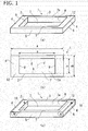
- FIGs. 1(a) to 1(c) illustrate a stirring bar 1 of a first embodiment of the invention.
- This stirring bar 1 includes a main body 2 obtained by molding a synthetic resin into a rectangular frame shape (a square shape of katakana) and Teflon (registered trademark) is used as a material of the main body 2.
- the main body 2 is constituted by four sides and includes two long side portions 3 which are parallel to each other and two short side portions 4 which are also parallel to each other.
- the long side portion 3 and the short side portion 4 are formed in a quadrangular prismatic shape having a rectangular cross-section and the ends of the long side portion 3 and the short side portion 4 are integrally connected to each other at the adjacent sides.
- the long side portion 3 and the short side portion 4 extend in a direction orthogonal to each other, but the invention is not limited thereto.
- the long side portion 3 and the short side portion 4 may be formed so as to extend at an angle other than 90°.
- the shape of the intersection portion between the long side portion 3 and the short side portion 4 may be, for example, a shape in which a corner is chamfered.
- a longitudinal length of an outer surface 5 of the long side portion 3 is indicated by A and a longitudinal length of an outer surface 6 of the short side portion 4 is indicated by B
- a relationship of A > B is established therebetween.
- the longitudinal length A of the outer surface 5 of the long side portion 3 is referred to as an "outer long side length A” or the like.
- the longitudinal length B of the outer surface 6 of the short side portion 4 is referred to as an "outer short side length B" or the like.
- a center portion of the main body 2 is provided with a through-hole 7 which penetrates the main body 2 in the thickness direction and is formed as a recess portion having an opening area 7a opening in a rectangular shape.
- This through-hole 7 is a rectangular parallelepiped space surrounded on all sides by an inner surface 8 of the long side portion 3 and an inner surface 9 of the short side portion 4.
- the (longitudinal) length a of the inner surface 8 of the long side portion 3 is a gap between the inner surfaces 9 of two short side portions 4 which are parallel to each other and can be an opening length of the through-hole 7.
- the (longitudinal) length b of the inner surface 9 of the short side portion 4 is a gap between the inner surfaces 8 of two long side portions 3 which are parallel to each other and can be an opening width of the through-hole 7.
- the length a is referred to as an "inner long side length a" or the like and the length b is referred to as an "inner short side length b" or the like in some cases.
- each long side portion 3 is uniformly formed of a synthetic resin as a material.
- a bar magnet (hereinafter, referred to as a "magnet") 10 which is a magnetic member is incorporated in each short side portion 4 as transparently illustrated in Fig. 1(c) .
- the inside of the short side portion 4 is formed by a synthetic resin which is a material of an outer portion and the magnet 10 having a specific gravity larger than that of the synthetic resin.
- the magnet 10 has one axial end as an N pole and the other axial end as an S pole as indicated by a symbol in the drawings and the axial direction matches the longitudinal direction of the short side portion 4. Further, the directions of two magnets 10 are determined so that the polarities are opposite to each other.
- the stirring bar 1 with such a structure is introduced into a reagent bottle 21 which is a container illustrated in Fig. 2(a) by, for example, a person using the stirring bar.
- the reagent bottle 21 is formed of glass and is colorless and transparent (or may be colored and transparent).
- the reagent bottle 21 is formed in a stepped cylindrical shape including a body portion 22 having a relatively large diameter and a neck portion 23 having a diameter smaller than the body portion 22.
- the reagent bottle 21 is attached (set) to a reagent tray (not illustrated) in, for example, an automatic analysis device (hereinafter, referred to as "analysis device") such as a blood coagulation analysis device in a standing posture while a lid (not illustrated) is removed and a mouth portion 24 faces upward.
- analysis device such as a blood coagulation analysis device in a standing posture while a lid (not illustrated) is removed and a mouth portion 24 faces upward.
- Fig. 2(a) schematically illustrates a state in which the reagent bottle 21 is set to an analysis device 30.
- the analysis device an operation is performed so that a rotational driving portion 31 is located at a position immediately below the reagent tray to which the reagent bottle 21 is set.
- the rotational driving portion 31 includes a magnetic force transmitting magnet which applies a magnetic force to the stirring bar 1 in the reagent bottle 21 or a rotation mechanism which rotates the magnetic force transmitting magnet. Then, when the rotational driving portion 31 is operated to rotate the magnetic force transmitting magnet (not illustrated), the stirring bar 1 in the reagent bottle 21 rotates in a synchronization state by the non-contact transmission of the magnetic force.
- the analysis device is provided with a dispensing reagent nozzle (hereinafter, referred to as a "nozzle") 32.
- This nozzle 32 is formed in a cylindrical shape and a diameter P of, for example, about 1 mm. Further, although not illustrated in the drawings, the nozzle 32 is supported by a movement mechanism enabling the movement in the horizontal direction or the height direction and is connected to a suction and ejection mechanism enabling the suction and the ejection of the reagent as a contained liquid.
- the analysis device of the embodiment is provided with a heater incorporated reagent heating flow path and one indicated by reference numeral 33 in Fig. 2(a) is a reagent heating heater provided in the movement mechanism. Then, the driving of the movement mechanism or the suction and ejection mechanism is performed by a nozzle driving unit 36 under the control of a control unit 35 provided in an operation unit 34 of the analysis device 30.
- the nozzle 32 having the above-described configuration enters the reagent bottle 21, stops at a predetermined height, and sucks a predetermined amount of the reagent so as to perform sampling. Further, although not illustrated in the drawings, the nozzle 32 rises to a state in which the tip (the lower end) comes out of the reagent bottle 21 and moves horizontally in this raised state. Then, the nozzle 32 is lowered after reaching, for example, the upper side of a target reaction container or the like from which a sample has been discharged and discharges a reagent into the reaction container or the like. Further, an analysis for a predetermined examination is automatically performed by an analysis unit 37 of the analysis device 30.
- the movement mechanism, the suction and ejection mechanism, the rotational driving portion 31, the nozzle 32, a holder 33, and the like provided in the analysis device various general types can be adopted.
- the nozzle 32 may be, for example, one in which a plurality of (two or more) nozzle bodies are mounted in parallel to each other.
- the stirring bar 1 When the stirring bar 1 is introduced into the reagent bottle 21, for example, the stirring bar naturally falls and sinks in the liquid reagent and stops when reaching an inner bottom portion 25 of the reagent bottle 21.
- the shape of the stirring bar 1 is a rectangular frame shape and the magnet 10 is incorporated in each of two short side portions 4 separated from each other. For this reason, the stirring bar 1 stops in a horizontal posture in which two long side portions 3 (and two short side portions 4) face each other.
- FIG. 2(b) is a diagram schematically illustrating a state of the stirring bar 1 rotating in the inner bottom portion 25 of the reagent bottle 21 when viewed from above. Then, in the drawing, the stirring bar 1 is indicated by a dashed line at the intermittent timing of the rotation angle every 30° and the dashed lines are combined.
- the stirring bar 1 is displaced (biased) from a center K of the inner bottom portion 25 of the reagent bottle 21 before the rotation of the stirring bar 1.
- Fig. 3(d) to be described later illustrates an example of the displaced state.
- a symbol T in Fig. 3(d) indicates a deviation amount of the center K of the inner bottom portion 25 of the reagent bottle 21 and a center J of the through-hole 7 of the stirring bar 1.
- the stirring bar 1 When the stirring bar 1 starts to rotate from a state before rotation illustrated with reference to Fig. 3(d) , the stirring bar 1 rotates at the center portion of the inner bottom portion 25 of the reagent bottle 21 as illustrated in Fig. 2 (b) due to the centering effect with the rotation. As described above, the stirring bar 1 is provided with the through-hole 7. For this reason, the center K of the inner bottom portion 25 is always visible through a true circular area (hereinafter, referred to as a "center area of the through-hole 7") 11 reaching a predetermined range from the center J of the through-hole 7 during the rotation of the stirring bar 1. Then, the size when the center area 11 is viewed from above is narrowed to be smaller than the size when the entire through-hole 7 is viewed from above, for example, when the stirring bar 1 is stopped.
- a true circular area hereinafter, referred to as a "center area of the through-hole 7”
- a reference numeral 27 and a two-dotted chain line in Fig. 2(a) is a liquid surface of the reagent which is lowered at the center portion and is raised at the outer peripheral portion due to the centrifugal force during stirring.
- the stirring bar 1 is stopped at the center of the inner bottom portion 25 of the reagent bottle 21 and the inner bottom portion 25 is exposed from the entire through-hole 7 after the rotation of the stirring bar 1 is stopped. For this reason, when stopping the rotation, the center K of the inner bottom portion 25 of the reagent bottle 21 is visible from the through-hole 7. Then, the tip of the nozzle 32 can be allowed to enter the through-hole 7 in such a manner that the nozzle 32 is lowered toward the center K of the inner bottom portion 25. In this way, it is also possible to sample the reagent by lowering the nozzle 32 after stopping the stirring.
- the position of the stirring bar 1 can be maintained to a certain degree by the magnetic force transmitting magnet (not illustrated) of the analysis device.
- the center J of the stirring bar 1 does not match the position of the center K of the inner bottom portion 25 can be assumed (an example is illustrated in Fig. 3(d) ).
- the nozzle 32 can be allowed to approach the inner bottom portion 25 by lowering the nozzle 32 toward the center K of the inner bottom portion 25.
- the size of the center area 11 in the through-hole 7 of the stirring bar 1 can be expressed by the above-described length b.
- the above-described length b is a gap (opening width) between the inner surfaces 8 of two long side portions 3 which are parallel to each other.
- the gap (opening width) between the inner surfaces 8 is constant not only at the center portion in the longitudinal direction but also the other portions.
- the center area 11 becomes a true circular area when viewed from above and its diameter r matches the gap b of the inner surface 8 (the opening width of the through-hole 7) as illustrated in Fig. 2(b) .
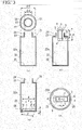
- Figs. 3(a) to 3(d) schematically illustrate a dimensional relationship of main parts of the reagent bottle 21 and the stirring bar 1 or a state when introducing the stirring bar 1 into the reagent bottle 21. Additionally, in Figs. 3(a) to 3(d) , hatching indicating a cross-section of the reagent bottle 21 is omitted to prevent the drawing from being complicated.
- a dimension of a main part of the reagent bottle 21 is indicated by a symbol D or a symbol d.
- the symbol D of them indicates a dimension of the inner diameter of the body portion 22 (hereinafter, referred to as a "body portion inner diameter") of the reagent bottle 21.
- the symbol d indicates the inner diameter of the mouth portion 24 (hereinafter, referred to as a "mouth portion inner diameter”) .
- the magnitude relationship between the body portion inner diameter D and the mouth portion inner diameter d is D > d.
- the body portion inner diameter D is assumed to match the diameter of the inner bottom portion 25 (hereinafter, referred to as an "inner bottom portion diameter") .
- the mouth portion inner diameter d of the embodiment is the same as the inner diameter of the neck portion 23 (hereinafter, referred to as a “neck portion inner diameter").
- the invention is not limited thereto and, for example, the body portion inner diameter and the inner bottom portion diameter may be slightly different from each other. Further, the mouth portion inner diameter d may be smaller than the neck portion inner diameter.
- the stirring bar 1 When introducing the stirring bar 1 into the reagent bottle 21, the stirring bar 1 is inserted into the mouth portion 24 in a direction in which two short side portions 4 are arranged in the vertical direction as illustrated in Fig. 3(b) . As described above, the stirring bar 1 naturally falls, but the stirring bar 1 is stopped at the inner bottom portion 25 while its posture is changed to a lying state inside the reagent bottle 21.
- Fig. 3(c) illustrates a dimension of a main part of the stirring bar 1 having a horizontal posture and a symbol E of the drawing indicates a diagonal length (hereinafter, referred to as a "short side outer diagonal length") of the stirring bar 1 from the upper end (or the lower end) of the outer surface 6 of one short side portion 4 to the lower end (or the upper end) of the outer surface 6 of the other short side portion 4.
- a symbol H of the drawing indicates a thickness of the stirring bar 1 and the thickness H is common to both the long side portion 3 and the short side portion 4. Further, the thickness H of the stirring bar 1 may be different between the long side portion 3 and the short side portion 4.
- the relationship (B ⁇ d ⁇ A) of (1) shows that the outer short side length B of the stirring bar 1 is smaller than the mouth portion inner diameter d of the reagent bottle 21 and the mouth portion inner diameter d is smaller than the outer long side length A of the stirring bar 1.
- the relationship (E ⁇ D) of (2) shows that the short side outer diagonal length E of the stirring bar 1 is smaller than the body portion inner diameter D of the reagent bottle 21.
- the relationship (b > P) of (3) shows that the inner short side length b of the stirring bar 1 is larger than the occupied area (passing area) of the nozzle 32.
- the "occupied area (passing area) of the nozzle 32" can be expressed by a cross-sectional area calculated by the diameter P of the nozzle 32 and a so-called “play (positional variation) " in a horizontal plane, this area can be paraphrased as, for example, the "occupied length (passing length) of the nozzle 32".
- the above-described stirring bar 1 has the following operation and effect. That is, a space is provided at the center portion of the stirring bar 1 due to the through-hole 7 and the space dimension is wider than the passing area of the nozzle 32. Then, the entrance area of the nozzle 32 can be secured by using the center portion of the through-hole 7 when the stirring bar 1 rotates or stops after rotation. For this reason, the lower end of the nozzle 32 can be allowed to reach a portion lower than the upper surface 12 of the stirring bar 1 through the through-hole 7 of the stirring bar 1 having a horizontal posture. Then, it is possible to suck the reagent by the nozzle 32 while the nozzle 32 approaches the inner bottom portion 25 of the reagent bottle 21 as close as possible.
- the reagent bottle 21 is replaced without using about 1.7 mL of the reagent stored to, for example, 10 mL in the reagent bottle 21 before opening.
- the stirring bar 1 of the embodiment since the stirring bar 1 of the embodiment is used, the remaining amount of the reagent can be reduced to about 1 mL during replacement. Then, since the amount of the discarded reagent can be reduced, there is a contribution to not only cost reduction but also environmental protection.
- the nozzle 32 can enter the through-hole 7 in any case of the rotation state and the stop state of the stirring bar 1 in such a manner that the nozzle 32 is lowered toward the center K of the inner bottom portion 25 in the reagent bottle 21. Then, the dead volume of the reagent bottle 21 can be reduced while using the conventional one as the reagent bottle 21 or the analysis device 30.
- the stirring bar 1 of the embodiment is formed in a rectangular shape on the whole and the length (the outer short side length B) of the short side portion 4 is shorter than the length (the outer long side length A) of the long side portion 3. For this reason, a person who uses the stirring bar 1 can narrow the width by pinching the stirring bar 1 so that the longitudinal direction of the long side portion 3 faces the vertical direction. For this reason, even when the stirring bar 1 is enlarged so that the length (the outer long side length A) of the long side portion 3 is longer than the inner diameter (the mouth portion inner diameter d) of the mouth portion 24 of the reagent bottle 21, the stirring bar 1 can introduced into the reagent bottle 21.
- the stirring bar 1 can occupy a wider area in the bottom portion of the reagent bottle 21 and hence the stirring efficiency during rotation can be improved. Further, since the through-hole 7 penetrating the main body 2 is provided, it is highly convenient in that the stirring bar can be used without distinguishing the front and back surfaces when introducing the stirring bar into the reagent bottle 21.
- each long side portion 3 or each short side portion 4 is a quadrangular prismatic shape
- the presence of the corners 13 can ensure a large contact area with the reagent compared to a case in which each of the side portions 3 and 4 has a columnar shape (a cross-sectional shape is a circle) and the outer dimensions are almost the same as those of the stirring bar of the embodiment, for example, as virtually indicated by a curve of a two-dotted chain R of Fig. 2(c) .
- it is easy to give a motion to the reagent during the rotation of the stirring bar 1 it is possible to efficiently perform stirring in a short time.
- the corner 13 of the short side portion 4 (which is also the corner of the end of the long side portion 3) can enter (be close to) a corner 28 of the reagent bottle 21.
- stagnation (retention) does not easily occur at the corner 28.
- Teflon registered trademark
- Teflon registered trademark
- PEEK polyetheretherketone
- the reagent can be used in various forms.
- the reagent contained in one reagent bottle 21 may be used up in one day or several days or may be used for a long period of time such as two weeks or thirty days. Then, the amount of the reagent in the reagent bottle 21 is smaller than the amount of the reagent at the start of use at the end of the use period related to such one reagent bottle 21. For this reason, generally, at the end of the use period, sufficient stirring can be performed with a short rotation time. Then, according to the stirring bar 1 of the embodiment, even when the reagent gradually decreases and the liquid surface of the reagent becomes lower than the height of the stirring bar 1, the reagent can still be used continuously.
- the stirring bar 1 of the embodiment since the stirring can be performed efficiently, it is possible to meet various demands. Further, it is conceivable that, for example, a composition in which a mixture settles immediately even with stirring and cannot be used as a reagent in the past can be used as a reagent.
- the characteristics of the stirring bar 1 such as a weight, a dimension of each part, an arrangement of the magnet 10, and a magnetic strength of the magnet 10 in consideration of the use environment such as the dimensions of reagent bottles to be used, the amount of reagents, viscosity, and non-uniformity of the composition or the specification of the magnet for transmitting magnetic force.
- the weight of the stirring bar 1 is relatively increased.
- the stirring efficiency can be increased by a relatively simple structure, it is easy to change the design relating to the shape and dimensions of each part for optimization.
- the shape of the long side portion 3 or the short side portion 4 is a quadrangular prismatic shape, but the invention is not limited thereto.
- various shapes such as a triangular prism, a cylinder, and a polygonal prism can be adopted.
- the cross-sectional shape of the long side portion 3 or the short side portion 4 in that case can be a regular triangle, an isosceles triangle, a circle, an ellipse, a polygon, or the like.
- various shapes such as a triangular prism, a quadrangular prism, and a polygonal prism can be adopted as the shape of the magnet 10.
- the cross-sectional shape may be a regular triangle, an isosceles triangle, a circle, an ellipse, a polygon, or the like.
- the characteristics of stirring by the stirring bar 1 can be improved by the function of the analysis device. For example, when the sedimentation amount of the reagent is large and strong stirring is required for a long period of time, it is possible to control the analysis device so that the number of rotations of the rotational driving portion 31 is relatively large. Also for the stirring time, it is also conceivable that the stirring bar 1 is rotated for a relatively short time in the case of a reagent in which a mixture is relatively unlikely to settle and the stirring bar is rotated for a long time in the case of a reagent in which a mixture is relatively easily settled in accordance with the setting of the control condition of the analysis device.
- Such control of the number of rotations in the analysis device is performed in advance as an initial setting (default) according to, for example, a difference in inspection item. Further, the rotation speed of the stirring bar 1 can be also changed by adjusting the number of rotations during stirring. The adjustment of the number of rotations can be also performed in accordance with the amount of liquid reagent remaining in the reagent bottle 21 (liquid level) .
- a method of detecting the liquid level it is conceivable that a method of detecting a change in capacitance at the tip of the reagent nozzle when the reagent nozzle comes into contact with the liquid surface is adopted.
- the adjustment of the number of rotations is performed, for example, in consideration of the generation of bubbles. It can be said that bubbles are easily generated when the liquid amount of the reagent is small or when the viscosity of the reagent is high. Further, there is a case in which bubbles are generated even when the number of rotations of the stirring bar is too high for the characteristics of the reagent. Then, for example, when performing the liquid surface detection as described above, the upper surface of the bubble may be detected as the liquid surface and the bubble may influence the accuracy of the liquid surface detection. For this reason, it is possible to detect bubbles in the analysis device and use the detection results for highly accurate reagent management.
- the bubble detection method for example, a case can be exemplified in which a control unit (not illustrated) of the analysis device determines that bubbles are generated when the liquid level height rises on the basis of a history of a detection result by performing a liquid level detection together whenever sucking the reagent. Further, the number of rotations can be adjusted so as to prevent liquid surface fluctuation in which the liquid surface of the reagent fluctuates up and down during the stirring.
- the stirring bar 1 For the shape of the stirring bar 1, a case in which the stirring bar 1 used once is used again is assumed. For example, it is possible to avoid irregularities and shapes having sharp corners as much as possible so that the stirring bar 1 can be easily cleaned and to facilitate removal of deposits during cleaning. Further, since the size of the reagent bottle 21 is usually standardized to some extent, the stirring bar 1 as in this embodiment can be mass-produced.
- the configuration of the stirring bar according to the invention is not limited to the above-described embodiment and can be modified into various forms. Additionally, in the following description, the same reference numerals will be given to the same parts as those of the embodiment (hereinafter, referred to as a "first embodiment") illustrated in Figs. 1 to 3 and description thereof will be omitted.
- Fig. 4 (a) illustrates a first modified example of the invention according to the first embodiment.
- the magnet 10 is incorporated in each of two short side portions 4, but as in a stirring bar 41 of the first modified example, the magnet 10 may be provided only in any one of the short side portions 4.
- the rotation stability can be maintained by aligning the weight balance while enlarging the outer shape dimension of the short side portion 4 without incorporating the magnet 10 therein.
- the magnet 10 can be incorporated in both or one of the long side portions 3 instead of the short side portion 4.
- a disk-shaped magnet 47 may be disposed in each of four corners of the main body 2.
- N and S poles are directed in the thickness direction of the main body 2 and the direction of polarities are determined so that the magnetic forces do not cancel each other. In this way, the entire weight balance can be easily adjusted.
- a recess portion 52 may be formed as in a stirring bar 51 of a third modified example illustrated in Fig. 4(c) . That is, the stirring bar 1 according to the first embodiment includes the through-hole 7 penetrating in the thickness direction, but as in the stirring bar 51 illustrated in Fig. 4(c) , a main body 53 may be provided with a recess portion 52 which is not penetrated and is closed by a bottom portion 54. Also in this case, the tip of the nozzle 32 can be lowered to be lower than the height of the upper surface 12 in the stirring bar 51 and the reagent accumulated in the recess portion 52 can be used.
- the stirring bar 51 with the recess portion 52 which is not penetrated is easily manufactured compared to the stirring bar 1 with the through-hole 7.
- the arrangement and size of the magnet may be such that at least a part of the magnet reaches the bottom portion of the recess portion 52.
- a plurality of (here, four) convex portions 57 facing outward can be provided.
- the convex portion 57 is formed at both ends of the outer surface 6 of the short side portion 4 so as to protrude in a semi-circular shape. Furthermore, the protrusion direction of the convex portion 57 matches the longitudinal direction of the long side portion 3 and the convex portion 57 has a curved surface 58 facing outward.
- the outer shape of the stirring bar 56 can be enlarged and the outermost surface (here, the curved surface 58) of the stirring bar 56 can approach an inner wall surface 22a of the reagent bottle 21. Then, in the stop state of the stirring bar 56, the matching between the center J of the stirring bar 56 and the center K of the reagent bottle 21 is easy and the centering of the stirring bar 56 is easy. Further, since the convex portion 57 is provided, the motion (flow) of the reagent around the convex portion 57 is easily generated during the rotation of the stirring bar 56 and the stirring efficiency can be improved.
- a stirring bar 61 can have a U-shape and the long side portions 63 can be connected to each other by a curved portion 64.
- two long side portions 63 can be compressed while being sandwiched between fingers and can be allowed to enter the mouth portion 24 while narrowing the width M on the whole.
- the magnet 10 is incorporated in the long side portion 63 and the magnet 10 does not exist in the curved portion 64.
- a folding structure can be adopted for the stirring bar.
- the stirring bar is folded and miniaturized when introducing the stirring bar into the reagent bottle 21 and its shape is restored and expanded after introducing the stirring bar into the reagent bottle.
- a groove may be provided in the upper surface 12 and the lower surface (reference numerals omitted) of various stirring bars 1, 41, 46, and 56 having the through-holes 7 so that the reagent flows into the through-holes 7 from outside the stirring bars 1, 41, 46, and 56.
- a radial shape including a radial shape of a straight line or a curved line
- the center J of the through-hole 7 at the center can be exemplified.
- Fig. 6(a) is a diagram schematically illustrating a state in which a stirring bar 71 according to the second embodiment of the invention has a horizontal posture when viewed from above.
- the long side portion 3 of the stirring bar 1 of the first embodiment has a thin wire shape instead of a prismatic shape.
- the long side portion 73 having a thin wire shape has a columnar cross-section and its diameter N is, for example, about 2 mm or less.
- the material of the long side portion 73 various materials such as synthetic resin and stainless steel can be used as long as they have sufficient rigidity. Further, even when the material of the long side portion 73 is magnetic, it is possible to prevent the rotation of the stirring bar 71 from being influenced by the magnetism of the long side portion 73 by making the magnetism of the long side portion 73 sufficiently weaker than the magnet (not illustrated) incorporated in the short side portion 74.
- the second embodiment illustrated in Fig. 6 (a) is modified such that the short side portion 4 of the first embodiment protrudes in the horizontal direction when the stirring bar is introduced into the reagent bottle 21. That is, in the stirring bar 71, the shape of the short side portion 74 becomes a parallelogram when the horizontal posture is viewed from above as illustrated in Fig. 6(a) . Then, the short side portion 74 is inclined by an angle ⁇ with respect to an axis F of the long side portion 73. Further, an axial end surface 74a of the short side portion 74 is inclined by a predetermined angle ⁇ with respect to a center axis G of the short side portion 74. In the embodiment, a relationship between the angle ⁇ and the angle ⁇ becomes ⁇ > ⁇ .
- the long side portion 73 is formed of a thin wire, the influence of the long side portion 73 on the movement (flow) of the reagent can be suppressed. Then, reagent bubbling can be prevented and the accuracy of liquid surface detection can be suppressed from being influenced by bubbles. Further, even when the liquid surface is detected during the stirring, the accuracy of the liquid surface detection can be suppressed from being influenced by the liquid surface fluctuation.
- the cross-sectional shape of the long side portion 73 formed of a thin wire various shapes such as an ellipse, a triangle, and a rhombus can be adopted in addition to a circle. Then, it is conceivable that the acute angle portion of the cross-section faces the outside in the horizontal direction in the reagent bottle 21 to reduce the resistance to the reagent during rotation.
- the stirring bar 71 of the second embodiment since the diameter N of the long side portion 73 is 2 mm, the area occupied by the long side portion 73 decreases and hence the long side portion 73 hardly interferes with the nozzle 32. Furthermore, since each portion of the short side portion 74 is provided so as to be inclined with respect to the long side portion 73 at angles ⁇ and ⁇ , an acute angle portion can be formed in the short side portion 74. Accordingly, the resistance of the reagent flowing during rotation can be reduced and bubbling and liquid surface fluctuation can be prevented.
- fins 77 may be provided in the short side portion 74 as in the stirring bar 76 illustrated in Fig. 6(b) so as to adjust the influence of the flow of the reagent.
- the adjustment of the flow using the fins 77 can be optimized by changing the shape, the number, the angle, the surface roughness, and the like of the fins 77.
- the fins 77 can be also applied to various stirring bars 1, 41, 46, 51, 56, 61, and the like exemplified as the first embodiment.
Landscapes
- Chemical & Material Sciences (AREA)
- Biochemistry (AREA)
- Physics & Mathematics (AREA)
- Health & Medical Sciences (AREA)
- Life Sciences & Earth Sciences (AREA)
- Analytical Chemistry (AREA)
- General Health & Medical Sciences (AREA)
- General Physics & Mathematics (AREA)
- Immunology (AREA)
- Pathology (AREA)
- Chemical Kinetics & Catalysis (AREA)
- Automatic Analysis And Handling Materials Therefor (AREA)
- Mixers With Rotating Receptacles And Mixers With Vibration Mechanisms (AREA)
Abstract
Description
- The present invention relates to a stirring bar which rotates inside a container and stirs a contained liquid such as a liquid and a stirring method using the stirring bar.
- Conventionally, a stirring method disclosed in
Patent Document 1 below is known. In the stirring method ofPatent Document 1, as described in Paragraphs 0009 and 0014,Figs. 1 and4 , and the like, a magnet rotation body (3) is disposed in an area just below the outside of a container (2) set in a container holder (11) and a stepping motor (12) is driven so that the magnet rotation body (3) rotates. A stainless stirring bar (4) is introduced into the container (2) and the magnet rotation body (3) is provided with a magnet (32). - Then, when a magnetic force of the magnet (32) is (magnetically) transmitted to the stirring bar (4) so that the magnet rotation body (3) rotates, the stirring bar (4) rotates horizontally and stirs a liquid inside the container (2). After the liquid is stirred by such a stirring method, a dispensing needle (5) is lowered into the container (2) and is stopped at a predetermined height so as to suck a predetermined amount of the liquid inside the container (2).
- Patent Document 1:
JP 2005-169303 A - Incidentally, when the above-described needle (5) can be lowered to the maximum and the suction can be performed while the tip of the needle (5) reaches a position just before a bottom surface of the container (2), most of the liquid can be used up without remain. In the stirring method described in
Patent Document 1 above, the bottom surface of the container (2) is provided with a convex portion (21) so that the stirring bar (4) in a rotation stop state is displaced. Then, the stirring bar (4) is separated from a vertical line of the needle (5) so that the tip of the needle (5) can approach the bottom surface of the container (2). - However, in the stirring method of
Patent Document 1, the dedicated container (2) having the convex portion (21) provided in the bottom surface is required and the lowering of the needle (5) is also restricted by the convex portion (21). That is, when the needle (5) is lowered to a height lower than the convex portion (21), the needle comes into contact with the convex portion (21). For this reason, since a dead space which is a space incapable of sucking a liquid is formed at least as much as the height of the convex portion (21), the liquid remains in the dead space. - The invention has been made to solve such problems and an object thereof is to provide a stirring bar and a stirring method capable of reducing a dead space inside a container and efficiently using a contained liquid in the container.
- In order to achieve the above-described object, the invention provides a stirring bar which is introduced into a container having an opening mouth portion and is rotated by a magnetic force transmitted from the outside of the container so as to stir a contained liquid in the container, including: a magnetic member which has a predetermined shape; and a main body that incorporates the magnetic member therein, in which the main body is provided with a recess portion which has an opening area corresponding to an opened area and is able to receive a nozzle lowered into the container in the opening area, and in which the stirring bar which is in a rotation state is able to receive the nozzle in a circular center area narrower than the opening area and having a diameter of an opening width of a center portion of the opening area. Here, the "recess portion" is a concept including not only a shape with a closed bottom, but also a shape with a bottom opened and penetrating the main body.
- Further, in order to achieve the above-described object, another invention provides the stirring bar such that the main body has a longitudinal direction directed to a falling direction when introducing the stirring bar into the container and a width direction extending in a direction intersecting the longitudinal direction, a length in the width direction is shorter than the opening width, and a length in the longitudinal direction is longer than the opening width.
- Further, in order to achieve the above-described object, another invention provides the stirring bar such that the recess portion penetrates the main body.
- Further, in order to achieve the above-described object, another invention provides a stirring method of introducing a stirring bar incorporating a magnetic member therein into a container having an opening mouth portion and rotating the stirring bar by a magnetic force transmitted from the outside of the container so as to stir a contained liquid in the container, in which a main body incorporating the magnetic member in the stirring bar is provided with a recess portion which has an opening area corresponding to an opened area and is able to receive a nozzle lowered into the container in the opening area, and in which the stirring bar which is in a rotation state is able to receive the nozzle in a circular center area narrower than the opening area and having a diameter of an opening width of a center portion of the opening area.
- Further, in order to achieve the above-described object, another invention provides the stirring method such that the recess portion penetrates the main body.
- According to this configuration, it is possible to provide a stirring bar and a stirring method capable of reducing a dead space inside a container and efficiently using a contained liquid in the container. Hereinafter, a reagent nozzle which sucks a reagent in a container (a reagent bottle) storing a liquid reagent will be described as an example.
-
-
Fig. 1(a) is a perspective view of a stirring bar according to a first embodiment of the invention,Fig. 1(b) is a plan view of the stirring bar, andFig. 1(c) is a perspective view in which a magnet inside the stirring bar is indicated by a dashed line; -
Fig. 2(a) is an explanatory diagram schematically illustrating a state in which a reagent nozzle is lowered into a reagent bottle having the stirring bar introduced thereinto,Fig. 2(b) is an explanatory diagram schematically illustrating a state of the stirring bar rotating inside the reagent bottle when viewed from above, andFig. 2 (c) is an enlarged explanatory diagram illustrating a state of a part of the stirring bar in an inner bottom portion of the reagent bottle when viewed from the side; -
Fig. 3(a) is an explanatory diagram illustrating a dimension of a main part of the reagent bottle indicated by a symbol,Fig. 3 (b) is an explanatory diagram illustrating a state in which the stirring bar is introduced into the reagent bottle,Fig. 3(c) is an explanatory diagram illustrating a state in which the stirring bar stops inside the reagent bottle, andFig. 3(d) is an explanatory diagram illustrating a state of the stirring bar stopped while being displaced from a center in the inner bottom portion of the reagent bottle when viewed from above; -
Fig. 4(a) is an explanatory diagram illustrating a modified example according to the stirring bar of the first embodiment,Fig. 4(b) is an explanatory diagram illustrating another modified example, andFig. 4(c) is an explanatory diagram illustrating another modified example; -
Fig. 5(a) is an explanatory diagram illustrating another modified example of the stirring bar of the first embodiment andFig. 5(b) is an explanatory diagram illustrating another modified example; and -
Fig. 6(a) is an explanatory diagram illustrating a stirring bar of a second embodiment andFig. 6(b) is an explanatory diagram illustrating a modified example of the stirring bar of the second embodiment. - Hereinafter, embodiments of a stirring bar of the invention will be described with reference to the drawings.
Figs. 1(a) to 1(c) illustrate astirring bar 1 of a first embodiment of the invention. Thisstirring bar 1 includes amain body 2 obtained by molding a synthetic resin into a rectangular frame shape (a square shape of katakana) and Teflon (registered trademark) is used as a material of themain body 2. - The
main body 2 is constituted by four sides and includes twolong side portions 3 which are parallel to each other and twoshort side portions 4 which are also parallel to each other. Thelong side portion 3 and theshort side portion 4 are formed in a quadrangular prismatic shape having a rectangular cross-section and the ends of thelong side portion 3 and theshort side portion 4 are integrally connected to each other at the adjacent sides. In the embodiment, thelong side portion 3 and theshort side portion 4 extend in a direction orthogonal to each other, but the invention is not limited thereto. For example, thelong side portion 3 and theshort side portion 4 may be formed so as to extend at an angle other than 90°. Further, the shape of the intersection portion between thelong side portion 3 and theshort side portion 4 may be, for example, a shape in which a corner is chamfered. - As illustrated in
Fig. 1(b) , when a longitudinal length of anouter surface 5 of thelong side portion 3 is indicated by A and a longitudinal length of anouter surface 6 of theshort side portion 4 is indicated by B, a relationship of A > B is established therebetween. Hereinafter, the longitudinal length A of theouter surface 5 of thelong side portion 3 is referred to as an "outer long side length A" or the like. Hereinafter, the longitudinal length B of theouter surface 6 of theshort side portion 4 is referred to as an "outer short side length B" or the like. - A center portion of the
main body 2 is provided with a through-hole 7 which penetrates themain body 2 in the thickness direction and is formed as a recess portion having anopening area 7a opening in a rectangular shape. This through-hole 7 is a rectangular parallelepiped space surrounded on all sides by aninner surface 8 of thelong side portion 3 and aninner surface 9 of theshort side portion 4. When the longitudinal length of theinner surface 8 of thelong side portion 3 is indicated by a and the longitudinal length of theinner surface 9 of theshort side portion 4 is indicated by b, a relationship of a > b is established therebetween. - Here, the (longitudinal) length a of the
inner surface 8 of thelong side portion 3 is a gap between theinner surfaces 9 of twoshort side portions 4 which are parallel to each other and can be an opening length of the through-hole 7. Further, the (longitudinal) length b of theinner surface 9 of theshort side portion 4 is a gap between theinner surfaces 8 of twolong side portions 3 which are parallel to each other and can be an opening width of the through-hole 7. Then, hereinafter, the length a is referred to as an "inner long side length a" or the like and the length b is referred to as an "inner short side length b" or the like in some cases. - The inside of each
long side portion 3 is uniformly formed of a synthetic resin as a material. In contrast, a bar magnet (hereinafter, referred to as a "magnet") 10 which is a magnetic member is incorporated in eachshort side portion 4 as transparently illustrated inFig. 1(c) . Then, the inside of theshort side portion 4 is formed by a synthetic resin which is a material of an outer portion and themagnet 10 having a specific gravity larger than that of the synthetic resin. Themagnet 10 has one axial end as an N pole and the other axial end as an S pole as indicated by a symbol in the drawings and the axial direction matches the longitudinal direction of theshort side portion 4. Further, the directions of twomagnets 10 are determined so that the polarities are opposite to each other. - The
stirring bar 1 with such a structure is introduced into areagent bottle 21 which is a container illustrated inFig. 2(a) by, for example, a person using the stirring bar. In the embodiment, thereagent bottle 21 is formed of glass and is colorless and transparent (or may be colored and transparent). Thereagent bottle 21 is formed in a stepped cylindrical shape including abody portion 22 having a relatively large diameter and aneck portion 23 having a diameter smaller than thebody portion 22. Further, thereagent bottle 21 is attached (set) to a reagent tray (not illustrated) in, for example, an automatic analysis device (hereinafter, referred to as "analysis device") such as a blood coagulation analysis device in a standing posture while a lid (not illustrated) is removed and amouth portion 24 faces upward. -
Fig. 2(a) schematically illustrates a state in which thereagent bottle 21 is set to ananalysis device 30. In the analysis device, an operation is performed so that arotational driving portion 31 is located at a position immediately below the reagent tray to which thereagent bottle 21 is set. Although not illustrated in the drawings, therotational driving portion 31 includes a magnetic force transmitting magnet which applies a magnetic force to thestirring bar 1 in thereagent bottle 21 or a rotation mechanism which rotates the magnetic force transmitting magnet. Then, when therotational driving portion 31 is operated to rotate the magnetic force transmitting magnet (not illustrated), the stirringbar 1 in thereagent bottle 21 rotates in a synchronization state by the non-contact transmission of the magnetic force. - The analysis device is provided with a dispensing reagent nozzle (hereinafter, referred to as a "nozzle") 32. This
nozzle 32 is formed in a cylindrical shape and a diameter P of, for example, about 1 mm. Further, although not illustrated in the drawings, thenozzle 32 is supported by a movement mechanism enabling the movement in the horizontal direction or the height direction and is connected to a suction and ejection mechanism enabling the suction and the ejection of the reagent as a contained liquid. Here, the analysis device of the embodiment is provided with a heater incorporated reagent heating flow path and one indicated byreference numeral 33 inFig. 2(a) is a reagent heating heater provided in the movement mechanism. Then, the driving of the movement mechanism or the suction and ejection mechanism is performed by anozzle driving unit 36 under the control of acontrol unit 35 provided in anoperation unit 34 of theanalysis device 30. - The
nozzle 32 having the above-described configuration enters thereagent bottle 21, stops at a predetermined height, and sucks a predetermined amount of the reagent so as to perform sampling. Further, although not illustrated in the drawings, thenozzle 32 rises to a state in which the tip (the lower end) comes out of thereagent bottle 21 and moves horizontally in this raised state. Then, thenozzle 32 is lowered after reaching, for example, the upper side of a target reaction container or the like from which a sample has been discharged and discharges a reagent into the reaction container or the like. Further, an analysis for a predetermined examination is automatically performed by ananalysis unit 37 of theanalysis device 30. - Here, as the movement mechanism, the suction and ejection mechanism, the
rotational driving portion 31, thenozzle 32, aholder 33, and the like provided in the analysis device, various general types can be adopted. Further, thenozzle 32 may be, for example, one in which a plurality of (two or more) nozzle bodies are mounted in parallel to each other. - When the stirring
bar 1 is introduced into thereagent bottle 21, for example, the stirring bar naturally falls and sinks in the liquid reagent and stops when reaching aninner bottom portion 25 of thereagent bottle 21. As described above, the shape of the stirringbar 1 is a rectangular frame shape and themagnet 10 is incorporated in each of twoshort side portions 4 separated from each other. For this reason, the stirringbar 1 stops in a horizontal posture in which two long side portions 3 (and two short side portions 4) face each other. - When the
rotational driving portion 31 of the analysis device is driven in this state, the stirringbar 1 rotates in a horizontal plane in the lying posture and stirs the reagent in thereagent bottle 21.Fig. 2(b) is a diagram schematically illustrating a state of the stirringbar 1 rotating in theinner bottom portion 25 of thereagent bottle 21 when viewed from above. Then, in the drawing, the stirringbar 1 is indicated by a dashed line at the intermittent timing of the rotation angle every 30° and the dashed lines are combined. - In many cases, the stirring
bar 1 is displaced (biased) from a center K of theinner bottom portion 25 of thereagent bottle 21 before the rotation of the stirringbar 1.Fig. 3(d) to be described later illustrates an example of the displaced state. Then, a symbol T inFig. 3(d) indicates a deviation amount of the center K of theinner bottom portion 25 of thereagent bottle 21 and a center J of the through-hole 7 of the stirringbar 1. - When the stirring
bar 1 starts to rotate from a state before rotation illustrated with reference toFig. 3(d) , the stirringbar 1 rotates at the center portion of theinner bottom portion 25 of thereagent bottle 21 as illustrated inFig. 2 (b) due to the centering effect with the rotation. As described above, the stirringbar 1 is provided with the through-hole 7. For this reason, the center K of theinner bottom portion 25 is always visible through a true circular area (hereinafter, referred to as a "center area of the through-hole 7") 11 reaching a predetermined range from the center J of the through-hole 7 during the rotation of the stirringbar 1. Then, the size when thecenter area 11 is viewed from above is narrowed to be smaller than the size when the entire through-hole 7 is viewed from above, for example, when the stirringbar 1 is stopped. - For this reason, even when the
nozzle 32 of the analysis device is lowered into thereagent bottle 21 toward the center of theinner bottom portion 25 as illustrated inFig. 2 (a) during the rotation of the stirringbar 1, the tip of thenozzle 32 passes through a height level of anupper surface 12 of the stirringbar 1 and enters thecenter area 11 of the through-hole 7. Then, thenozzle 32 can be lowered further so that the tip of thenozzle 32 can approach theinner bottom portion 25 of thereagent bottle 21 as close as possible. In this way, since the stirringbar 1 is provided with the through-hole 7 which produces thecenter area 11 during the rotation, thenozzle 32 can be lowered to theinner bottom portion 25 of thereagent bottle 21 as close as possible. - In contrast, as illustrated in
Fig. 2(b) , there is a timing at which theshort side portion 4 or thelong side portion 3 passes in an area (hereinafter, referred to as an "outer peripheral area of theinner bottom portion 25") 26 on the outside of thecenter area 11 in the through-hole 7 with the rotational displacement of the stirringbar 1. For this reason, when thenozzle 32 is lowered toward the outerperipheral area 26 of theinner bottom portion 25 so that thenozzle 32 reaches a height level of theupper surface 12 of the stirringbar 1 during the rotation of the stirringbar 1, the lower end of thenozzle 32 contacts and interferes with the stirringbar 1. Thus, thenozzle 32 can be allowed to enter the through-hole 7 without contacting the stirringbar 1 as described above in such a manner that thenozzle 32 is lowered to a position entering thecenter area 11 when sucking the reagent during the rotation of the stirringbar 1. - Further, when the lowering position of the
nozzle 32 is within the range of thecenter area 11 in the through-hole 7 even when the lowering position is displaced from the center K of theinner bottom portion 25, thenozzle 32 can be allowed to enter the through-hole 7 of the stirringbar 1 in the rotation state. Here, one indicated by areference numeral 27 and a two-dotted chain line inFig. 2(a) is a liquid surface of the reagent which is lowered at the center portion and is raised at the outer peripheral portion due to the centrifugal force during stirring. - Meanwhile, the stirring
bar 1 is stopped at the center of theinner bottom portion 25 of thereagent bottle 21 and theinner bottom portion 25 is exposed from the entire through-hole 7 after the rotation of the stirringbar 1 is stopped. For this reason, when stopping the rotation, the center K of theinner bottom portion 25 of thereagent bottle 21 is visible from the through-hole 7. Then, the tip of thenozzle 32 can be allowed to enter the through-hole 7 in such a manner that thenozzle 32 is lowered toward the center K of theinner bottom portion 25. In this way, it is also possible to sample the reagent by lowering thenozzle 32 after stopping the stirring. - In such a stop state of the stirring
bar 1, the position of the stirringbar 1 can be maintained to a certain degree by the magnetic force transmitting magnet (not illustrated) of the analysis device. However, in some cases, a case in which the center J of the stirringbar 1 does not match the position of the center K of theinner bottom portion 25 can be assumed (an example is illustrated inFig. 3(d) ). Even in such a case, when the center K of theinner bottom portion 25 is within the through-hole 7, thenozzle 32 can be allowed to approach theinner bottom portion 25 by lowering thenozzle 32 toward the center K of theinner bottom portion 25. - In the stirring
bar 1 that exhibits the above-described function, the following description is also possible. For example, the size of thecenter area 11 in the through-hole 7 of the stirringbar 1 can be expressed by the above-described length b. The above-described length b is a gap (opening width) between theinner surfaces 8 of twolong side portions 3 which are parallel to each other. In the embodiment, since the opening shape of the through-hole 7 is a rectangular shape, the gap (opening width) between theinner surfaces 8 is constant not only at the center portion in the longitudinal direction but also the other portions. Then, in the rotation state of the stirringbar 1, thecenter area 11 becomes a true circular area when viewed from above and its diameter r matches the gap b of the inner surface 8 (the opening width of the through-hole 7) as illustrated inFig. 2(b) . -
Figs. 3(a) to 3(d) schematically illustrate a dimensional relationship of main parts of thereagent bottle 21 and the stirringbar 1 or a state when introducing the stirringbar 1 into thereagent bottle 21. Additionally, inFigs. 3(a) to 3(d) , hatching indicating a cross-section of thereagent bottle 21 is omitted to prevent the drawing from being complicated. - In
Fig. 3(a) , a dimension of a main part of thereagent bottle 21 is indicated by a symbol D or a symbol d. The symbol D of them indicates a dimension of the inner diameter of the body portion 22 (hereinafter, referred to as a "body portion inner diameter") of thereagent bottle 21. Further, the symbol d indicates the inner diameter of the mouth portion 24 (hereinafter, referred to as a "mouth portion inner diameter") . Then, the magnitude relationship between the body portion inner diameter D and the mouth portion inner diameter d is D > d. - Here, in the embodiment, the body portion inner diameter D is assumed to match the diameter of the inner bottom portion 25 (hereinafter, referred to as an "inner bottom portion diameter") . Further, the mouth portion inner diameter d of the embodiment is the same as the inner diameter of the neck portion 23 (hereinafter, referred to as a "neck portion inner diameter"). However, the invention is not limited thereto and, for example, the body portion inner diameter and the inner bottom portion diameter may be slightly different from each other. Further, the mouth portion inner diameter d may be smaller than the neck portion inner diameter.
- When introducing the stirring
bar 1 into thereagent bottle 21, the stirringbar 1 is inserted into themouth portion 24 in a direction in which twoshort side portions 4 are arranged in the vertical direction as illustrated inFig. 3(b) . As described above, the stirringbar 1 naturally falls, but the stirringbar 1 is stopped at theinner bottom portion 25 while its posture is changed to a lying state inside thereagent bottle 21. -
Fig. 3(c) illustrates a dimension of a main part of the stirringbar 1 having a horizontal posture and a symbol E of the drawing indicates a diagonal length (hereinafter, referred to as a "short side outer diagonal length") of the stirringbar 1 from the upper end (or the lower end) of theouter surface 6 of oneshort side portion 4 to the lower end (or the upper end) of theouter surface 6 of the othershort side portion 4. Further, a symbol H of the drawing indicates a thickness of the stirringbar 1 and the thickness H is common to both thelong side portion 3 and theshort side portion 4. Further, the thickness H of the stirringbar 1 may be different between thelong side portion 3 and theshort side portion 4. - The dimensions of respective parts of the stirring
bar 1, thereagent bottle 21, and thenozzle 32 described above can be summarized as below, a relationship such as (1) to (3) below is established between these sizes. - A: Outer long side length of stirring
bar 1 - a: Inner long side length of stirring
bar 1 - B: Outer short side length of stirring
bar 1 - b: Inner short side length of stirring
bar 1 - D: Body portion inner diameter D of
reagent bottle 21 - d: Mouth portion inner diameter of
reagent bottle 21 - E: Short side outer diagonal length of stirring
bar 1 - Among these relationships, the relationship (B < d < A) of (1) shows that the outer short side length B of the stirring
bar 1 is smaller than the mouth portion inner diameter d of thereagent bottle 21 and the mouth portion inner diameter d is smaller than the outer long side length A of the stirringbar 1. Further, the relationship (E < D) of (2) shows that the short side outer diagonal length E of the stirringbar 1 is smaller than the body portion inner diameter D of thereagent bottle 21. - Further, the relationship (b > P) of (3) shows that the inner short side length b of the stirring
bar 1 is larger than the occupied area (passing area) of thenozzle 32. Here, since the "occupied area (passing area) of thenozzle 32" can be expressed by a cross-sectional area calculated by the diameter P of thenozzle 32 and a so-called "play (positional variation) " in a horizontal plane, this area can be paraphrased as, for example, the "occupied length (passing length) of thenozzle 32". - The above-described
stirring bar 1 has the following operation and effect. That is, a space is provided at the center portion of the stirringbar 1 due to the through-hole 7 and the space dimension is wider than the passing area of thenozzle 32. Then, the entrance area of thenozzle 32 can be secured by using the center portion of the through-hole 7 when the stirringbar 1 rotates or stops after rotation. For this reason, the lower end of thenozzle 32 can be allowed to reach a portion lower than theupper surface 12 of the stirringbar 1 through the through-hole 7 of the stirringbar 1 having a horizontal posture. Then, it is possible to suck the reagent by thenozzle 32 while thenozzle 32 approaches theinner bottom portion 25 of thereagent bottle 21 as close as possible. - As a result, it is possible to reduce the size of a dead space which is an area not touched by the
nozzle 32 to a minimum. Further, most of the reagent in thereagent bottle 21 can be used up together with the reagent outside the stirringbar 1 and thus the reagent can be used without waste. Then, since the amount of the reagent inside thereagent bottle 21 can be reduced in advance or the frequency of replacement of thereagent bottle 21 can be lowered compared to the related art having relatively many dead spaces, it is possible to reduce the cost of the reagent. - Conventionally, there is a case in which the
reagent bottle 21 is replaced without using about 1.7 mL of the reagent stored to, for example, 10 mL in thereagent bottle 21 before opening. However, since the stirringbar 1 of the embodiment is used, the remaining amount of the reagent can be reduced to about 1 mL during replacement. Then, since the amount of the discarded reagent can be reduced, there is a contribution to not only cost reduction but also environmental protection. - Further, according to the stirring
bar 1 of the embodiment, thenozzle 32 can enter the through-hole 7 in any case of the rotation state and the stop state of the stirringbar 1 in such a manner that thenozzle 32 is lowered toward the center K of theinner bottom portion 25 in thereagent bottle 21. Then, the dead volume of thereagent bottle 21 can be reduced while using the conventional one as thereagent bottle 21 or theanalysis device 30. - Further, the stirring
bar 1 of the embodiment is formed in a rectangular shape on the whole and the length (the outer short side length B) of theshort side portion 4 is shorter than the length (the outer long side length A) of thelong side portion 3. For this reason, a person who uses the stirringbar 1 can narrow the width by pinching the stirringbar 1 so that the longitudinal direction of thelong side portion 3 faces the vertical direction. For this reason, even when the stirringbar 1 is enlarged so that the length (the outer long side length A) of thelong side portion 3 is longer than the inner diameter (the mouth portion inner diameter d) of themouth portion 24 of thereagent bottle 21, the stirringbar 1 can introduced into thereagent bottle 21. Further, since the length (the outer long side length A) of thelong side portion 3 is long, the stirringbar 1 can occupy a wider area in the bottom portion of thereagent bottle 21 and hence the stirring efficiency during rotation can be improved. Further, since the through-hole 7 penetrating themain body 2 is provided, it is highly convenient in that the stirring bar can be used without distinguishing the front and back surfaces when introducing the stirring bar into thereagent bottle 21. - Further, since the shape of each
long side portion 3 or eachshort side portion 4 is a quadrangular prismatic shape, the presence of thecorners 13 can ensure a large contact area with the reagent compared to a case in which each of theside portions Fig. 2(c) . For this reason, since it is easy to give a motion to the reagent during the rotation of the stirringbar 1, it is possible to efficiently perform stirring in a short time. - Further, as illustrated in
Fig. 2(c) , in theinner bottom portion 25 of thereagent bottle 21, thecorner 13 of the short side portion 4 (which is also the corner of the end of the long side portion 3) can enter (be close to) acorner 28 of thereagent bottle 21. For this reason, since the stirringbar 1 can be brought into contact with the reagent even at thecorner 28 of thereagent bottle 21 and the reagent can be easily moved also at thecorner 28, stagnation (retention) does not easily occur at thecorner 28. - Further, according to the stirring
bar 1 of the embodiment, since Teflon (registered trademark) having excellent chemical resistance and self-lubricating property is used as the base material of themain body 2, it is possible to prevent the stirringbar 1 from influencing the properties of the reagent. As long as similar characteristics can be obtained, a material other than Teflon (registered trademark) can be used as the base material of themain body 2. It is conceivable that, for example, as a material other than Teflon (registered trademark), PEEK (polyetheretherketone) or the like is used. - Further, in general, the reagent can be used in various forms. For example, the reagent contained in one
reagent bottle 21 may be used up in one day or several days or may be used for a long period of time such as two weeks or thirty days. Then, the amount of the reagent in thereagent bottle 21 is smaller than the amount of the reagent at the start of use at the end of the use period related to such onereagent bottle 21. For this reason, generally, at the end of the use period, sufficient stirring can be performed with a short rotation time. Then, according to the stirringbar 1 of the embodiment, even when the reagent gradually decreases and the liquid surface of the reagent becomes lower than the height of the stirringbar 1, the reagent can still be used continuously. - Regarding the necessity of stirring the reagent, even when the same item is inspected using the same reagent, there are cases in which the stirring is required or not required, for example, due to differences in companies and research institutions. Further, depending on the type and composition of the reagent, there are those in which the sedimentation of the compound does not easily occur and a uniform system is easily maintained and those in which the sedimentation easily occurs and a uniform system is hardly maintained (they easily become non-uniform) . Furthermore, there is a case in which the reagent needs to be stirred constantly while using the reagent or a case in which the stirring is performed periodically and the stirring need not be performed at other times. Further, there is a case in which the stirring needs to be performed constantly even when the number of rotations is small and the stirring is weak. According to the stirring
bar 1 of the embodiment, since the stirring can be performed efficiently, it is possible to meet various demands. Further, it is conceivable that, for example, a composition in which a mixture settles immediately even with stirring and cannot be used as a reagent in the past can be used as a reagent. - Further, it is preferable to optimize the characteristics of the stirring
bar 1 such as a weight, a dimension of each part, an arrangement of themagnet 10, and a magnetic strength of themagnet 10 in consideration of the use environment such as the dimensions of reagent bottles to be used, the amount of reagents, viscosity, and non-uniformity of the composition or the specification of the magnet for transmitting magnetic force. For example, when the sedimentation amount of the reagent is large and strong stirring is required, it is conceivable that the weight of the stirringbar 1 is relatively increased. Then, according to the stirringbar 1 of the embodiment, since the stirring efficiency can be increased by a relatively simple structure, it is easy to change the design relating to the shape and dimensions of each part for optimization. - Further, in the embodiment, the shape of the
long side portion 3 or theshort side portion 4 is a quadrangular prismatic shape, but the invention is not limited thereto. For example, various shapes such as a triangular prism, a cylinder, and a polygonal prism can be adopted. Then, the cross-sectional shape of thelong side portion 3 or theshort side portion 4 in that case can be a regular triangle, an isosceles triangle, a circle, an ellipse, a polygon, or the like. Further, various shapes such as a triangular prism, a quadrangular prism, and a polygonal prism can be adopted as the shape of themagnet 10. Then, the cross-sectional shape may be a regular triangle, an isosceles triangle, a circle, an ellipse, a polygon, or the like. - The characteristics of stirring by the stirring
bar 1 can be improved by the function of the analysis device. For example, when the sedimentation amount of the reagent is large and strong stirring is required for a long period of time, it is possible to control the analysis device so that the number of rotations of therotational driving portion 31 is relatively large. Also for the stirring time, it is also conceivable that the stirringbar 1 is rotated for a relatively short time in the case of a reagent in which a mixture is relatively unlikely to settle and the stirring bar is rotated for a long time in the case of a reagent in which a mixture is relatively easily settled in accordance with the setting of the control condition of the analysis device. - Such control of the number of rotations in the analysis device is performed in advance as an initial setting (default) according to, for example, a difference in inspection item. Further, the rotation speed of the stirring
bar 1 can be also changed by adjusting the number of rotations during stirring. The adjustment of the number of rotations can be also performed in accordance with the amount of liquid reagent remaining in the reagent bottle 21 (liquid level) . As a method of detecting the liquid level, it is conceivable that a method of detecting a change in capacitance at the tip of the reagent nozzle when the reagent nozzle comes into contact with the liquid surface is adopted. - It is conceivable that the adjustment of the number of rotations is performed, for example, in consideration of the generation of bubbles. It can be said that bubbles are easily generated when the liquid amount of the reagent is small or when the viscosity of the reagent is high. Further, there is a case in which bubbles are generated even when the number of rotations of the stirring bar is too high for the characteristics of the reagent. Then, for example, when performing the liquid surface detection as described above, the upper surface of the bubble may be detected as the liquid surface and the bubble may influence the accuracy of the liquid surface detection. For this reason, it is possible to detect bubbles in the analysis device and use the detection results for highly accurate reagent management. As the bubble detection method, for example, a case can be exemplified in which a control unit (not illustrated) of the analysis device determines that bubbles are generated when the liquid level height rises on the basis of a history of a detection result by performing a liquid level detection together whenever sucking the reagent. Further, the number of rotations can be adjusted so as to prevent liquid surface fluctuation in which the liquid surface of the reagent fluctuates up and down during the stirring.
- For the shape of the stirring
bar 1, a case in which the stirringbar 1 used once is used again is assumed. For example, it is possible to avoid irregularities and shapes having sharp corners as much as possible so that the stirringbar 1 can be easily cleaned and to facilitate removal of deposits during cleaning. Further, since the size of thereagent bottle 21 is usually standardized to some extent, the stirringbar 1 as in this embodiment can be mass-produced. - Additionally, the configuration of the stirring bar according to the invention is not limited to the above-described embodiment and can be modified into various forms. Additionally, in the following description, the same reference numerals will be given to the same parts as those of the embodiment (hereinafter, referred to as a "first embodiment") illustrated in
Figs. 1 to 3 and description thereof will be omitted. - For example,
Fig. 4 (a) illustrates a first modified example of the invention according to the first embodiment. As described above, in the stirringbar 1 according to the first embodiment, themagnet 10 is incorporated in each of twoshort side portions 4, but as in a stirringbar 41 of the first modified example, themagnet 10 may be provided only in any one of theshort side portions 4. However, in this case, since a weight balance changes, a case in which the rotation is not easily stabilized during the rotation of the stirringbar 41 can be conceived. However, the rotation stability can be maintained by aligning the weight balance while enlarging the outer shape dimension of theshort side portion 4 without incorporating themagnet 10 therein. Further, although not illustrated in the drawings, themagnet 10 can be incorporated in both or one of thelong side portions 3 instead of theshort side portion 4. - Further, as in a stirring
bar 46 of a second modified example illustrated inFig. 4(b) , a disk-shapedmagnet 47 may be disposed in each of four corners of themain body 2. In themagnet 47, N and S poles are directed in the thickness direction of themain body 2 and the direction of polarities are determined so that the magnetic forces do not cancel each other. In this way, the entire weight balance can be easily adjusted. - Further, a
recess portion 52 may be formed as in a stirringbar 51 of a third modified example illustrated inFig. 4(c) . That is, the stirringbar 1 according to the first embodiment includes the through-hole 7 penetrating in the thickness direction, but as in the stirringbar 51 illustrated inFig. 4(c) , amain body 53 may be provided with arecess portion 52 which is not penetrated and is closed by abottom portion 54. Also in this case, the tip of thenozzle 32 can be lowered to be lower than the height of theupper surface 12 in the stirringbar 51 and the reagent accumulated in therecess portion 52 can be used. In this way, the stirringbar 51 with therecess portion 52 which is not penetrated is easily manufactured compared to the stirringbar 1 with the through-hole 7. Further, the arrangement and size of the magnet (not illustrated) may be such that at least a part of the magnet reaches the bottom portion of therecess portion 52. - Further, as in a stirring
bar 56 of a fourth modified example illustrated inFig. 5(a) , a plurality of (here, four)convex portions 57 facing outward can be provided. Theconvex portion 57 is formed at both ends of theouter surface 6 of theshort side portion 4 so as to protrude in a semi-circular shape. Furthermore, the protrusion direction of theconvex portion 57 matches the longitudinal direction of thelong side portion 3 and theconvex portion 57 has acurved surface 58 facing outward. Since such aconvex portion 57 is provided, the outer shape of the stirringbar 56 can be enlarged and the outermost surface (here, the curved surface 58) of the stirringbar 56 can approach aninner wall surface 22a of thereagent bottle 21. Then, in the stop state of the stirringbar 56, the matching between the center J of the stirringbar 56 and the center K of thereagent bottle 21 is easy and the centering of the stirringbar 56 is easy. Further, since theconvex portion 57 is provided, the motion (flow) of the reagent around theconvex portion 57 is easily generated during the rotation of the stirringbar 56 and the stirring efficiency can be improved. - Further, as in a fifth modified example illustrated in
Fig. 5(b) , a stirringbar 61 can have a U-shape and thelong side portions 63 can be connected to each other by acurved portion 64. In this way, when introducing the stirring bar into thereagent bottle 21, twolong side portions 63 can be compressed while being sandwiched between fingers and can be allowed to enter themouth portion 24 while narrowing the width M on the whole. Additionally, in the fourth modified example, themagnet 10 is incorporated in thelong side portion 63 and themagnet 10 does not exist in thecurved portion 64. - Further, although not illustrated in the drawings, a folding structure can be adopted for the stirring bar. For example, the stirring bar is folded and miniaturized when introducing the stirring bar into the
reagent bottle 21 and its shape is restored and expanded after introducing the stirring bar into the reagent bottle. Further, when there is no influence on the reagent, it is possible to adopt a structure or material that swells and expands when immersed in the reagent. Further, a groove may be provided in theupper surface 12 and the lower surface (reference numerals omitted) of various stirringbars holes 7 so that the reagent flows into the through-holes 7 from outside the stirringbars hole 7 at the center can be exemplified. - Next, a second embodiment of the invention will be described.
Fig. 6(a) is a diagram schematically illustrating a state in which a stirringbar 71 according to the second embodiment of the invention has a horizontal posture when viewed from above. In the stirringbar 71, thelong side portion 3 of the stirringbar 1 of the first embodiment has a thin wire shape instead of a prismatic shape. Thelong side portion 73 having a thin wire shape has a columnar cross-section and its diameter N is, for example, about 2 mm or less. - Here, as the material of the
long side portion 73, various materials such as synthetic resin and stainless steel can be used as long as they have sufficient rigidity. Further, even when the material of thelong side portion 73 is magnetic, it is possible to prevent the rotation of the stirringbar 71 from being influenced by the magnetism of thelong side portion 73 by making the magnetism of thelong side portion 73 sufficiently weaker than the magnet (not illustrated) incorporated in theshort side portion 74. - Further, the second embodiment illustrated in
Fig. 6 (a) is modified such that theshort side portion 4 of the first embodiment protrudes in the horizontal direction when the stirring bar is introduced into thereagent bottle 21. That is, in the stirringbar 71, the shape of theshort side portion 74 becomes a parallelogram when the horizontal posture is viewed from above as illustrated inFig. 6(a) . Then, theshort side portion 74 is inclined by an angle α with respect to an axis F of thelong side portion 73. Further, anaxial end surface 74a of theshort side portion 74 is inclined by a predetermined angle β with respect to a center axis G of theshort side portion 74. In the embodiment, a relationship between the angle α and the angle β becomes α > β. - According to such a stirring
bar 71 of the second embodiment, since thelong side portion 73 is formed of a thin wire, the influence of thelong side portion 73 on the movement (flow) of the reagent can be suppressed. Then, reagent bubbling can be prevented and the accuracy of liquid surface detection can be suppressed from being influenced by bubbles. Further, even when the liquid surface is detected during the stirring, the accuracy of the liquid surface detection can be suppressed from being influenced by the liquid surface fluctuation. Here, as the cross-sectional shape of thelong side portion 73 formed of a thin wire, various shapes such as an ellipse, a triangle, and a rhombus can be adopted in addition to a circle. Then, it is conceivable that the acute angle portion of the cross-section faces the outside in the horizontal direction in thereagent bottle 21 to reduce the resistance to the reagent during rotation. - Further, according to the stirring
bar 71 of the second embodiment, since the diameter N of thelong side portion 73 is 2 mm, the area occupied by thelong side portion 73 decreases and hence thelong side portion 73 hardly interferes with thenozzle 32. Furthermore, since each portion of theshort side portion 74 is provided so as to be inclined with respect to thelong side portion 73 at angles α and β, an acute angle portion can be formed in theshort side portion 74. Accordingly, the resistance of the reagent flowing during rotation can be reduced and bubbling and liquid surface fluctuation can be prevented. - Further,
fins 77 may be provided in theshort side portion 74 as in the stirringbar 76 illustrated inFig. 6(b) so as to adjust the influence of the flow of the reagent. The adjustment of the flow using thefins 77 can be optimized by changing the shape, the number, the angle, the surface roughness, and the like of thefins 77. Additionally, thefins 77 can be also applied to various stirringbars -
- 1
- STIRRING BAR
- 2
- MAIN BODY
- 3
- LONG SIDE PORTION
- 4
- SHORT SIDE PORTION
- 7
- THROUGH-HOLE (RECESS PORTION)
- 7a
- OPENING AREA
- 10
- MAGNET (MAGNETIC MEMBER)
- 11
- CENTER AREA
- 21
- REAGENT BOTTLE (CONTAINER)
- 32
- NOZZLE
- b
- INNER SHORT SIDE LENGTH (OPENING WIDTH)
- d
- MOUTH PORTION INNER DIAMETER OF REAGENT BOTTLE


Claims (5)
- A stirring bar which has a magnetic member having a predetermined shape and a main body having the magnetic member incorporated therein, and is introduced into a container having an opening mouth portion and is rotated by a magnetic force transmitted from the outside of the container so as to stir a contained liquid in the container, comprising:wherein the main body has an opening area in which a recess portion is formed, and the recess portion is able to accept therein a nozzle lowered into the container, andwherein the stirring bar which is in a rotation state is able to accept the nozzle in a circular center area narrower than the opening area and having a diameter of an opening width of a center portion of the opening area.
- The stirring bar according to claim 1,
wherein the main body has a longitudinal direction directed to a falling direction when introducing the stirring bar into the container and a width direction extending in a direction intersecting the longitudinal direction, a length in the width direction is shorter than the opening width, and a length in the longitudinal direction is longer than the opening width. - The stirring bar according to claim 1 or 2,
wherein the recess portion penetrates the main body. - A stirring method of introducing a stirring bar having a magnetic member therein into a container having an opening mouth portion and rotating the stirring bar by a magnetic force transmitted from the outside of the container so as to stir a contained liquid in the container,
wherein a main body having the magnetic member in the stirring bar has an opening area in which a recess portion is formed, and the recess portion is able to accept therein a nozzle lowered into the container, and
wherein the stirring bar which is in a rotation state is able to accept the nozzle in a circular center area narrower than the opening area and having a diameter of an opening width of a center portion of the opening area. - The stirring method according to claim 4,
wherein the recess portion penetrates the main body.
Applications Claiming Priority (2)
| Application Number | Priority Date | Filing Date | Title |
|---|---|---|---|
| JP2017249188 | 2017-12-26 | ||
| PCT/JP2018/044867 WO2019131039A1 (en) | 2017-12-26 | 2018-12-06 | Stirring bar and stirring method |
Publications (2)
| Publication Number | Publication Date |
|---|---|
| EP3733273A1 true EP3733273A1 (en) | 2020-11-04 |
| EP3733273A4 EP3733273A4 (en) | 2021-09-01 |
Family
ID=67063529
Family Applications (1)
| Application Number | Title | Priority Date | Filing Date |
|---|---|---|---|
| EP18893357.6A Pending EP3733273A4 (en) | 2017-12-26 | 2018-12-06 | AGITATION BAR AND AGITATION METHOD |
Country Status (5)
| Country | Link |
|---|---|
| US (1) | US11471843B2 (en) |
| EP (1) | EP3733273A4 (en) |
| JP (1) | JP7328152B2 (en) |
| CN (1) | CN111565831A (en) |
| WO (1) | WO2019131039A1 (en) |
Family Cites Families (13)
| Publication number | Priority date | Publication date | Assignee | Title |
|---|---|---|---|---|
| DE2017472A1 (en) * | 1970-04-11 | 1971-11-04 | Roehm Gmbh | Magnetic agitator for small vessels |
| JPH08257387A (en) * | 1995-03-27 | 1996-10-08 | Meguro Kagaku Kogyo Kk | Stirring device, stirring container and stirrer |
| DE19615117A1 (en) * | 1996-04-17 | 1997-10-23 | Bayer Ag | Chemical reactor with magnetic stirrer |
| JP2002011342A (en) * | 2000-06-28 | 2002-01-15 | Moritex Corp | Compound synthesizer and stirrer used for it |
| JP4385249B2 (en) | 2003-12-12 | 2009-12-16 | 日本パルスモーター株式会社 | Stirring container |
| JP2005262013A (en) * | 2004-03-16 | 2005-09-29 | Nokodai Tlo Kk | Stirrer and stirrer |
| JP2009183831A (en) * | 2008-02-05 | 2009-08-20 | Keio Gijuku | Powder stirrer and particle coating method |
| CN202516513U (en) * | 2012-04-06 | 2012-11-07 | 董惠君 | Stirring component for dye solution |
| DE102012008612A1 (en) | 2012-04-27 | 2013-10-31 | Ika-Werke Gmbh & Co. Kg | Temperature measuring device |
| WO2016080509A1 (en) * | 2014-11-21 | 2016-05-26 | 積水メディカル株式会社 | Container for specimen dilution |
| WO2016186063A1 (en) * | 2015-05-18 | 2016-11-24 | シャープ株式会社 | Stirrer and stirring device |
| JP6068709B2 (en) | 2015-05-18 | 2017-01-25 | シャープ株式会社 | Stirrer and stirrer |
| CN107456912B (en) * | 2017-08-07 | 2024-01-05 | 深圳市浪尖设计有限公司 | Embedded magnetic stirrer |
-
2018
- 2018-12-06 WO PCT/JP2018/044867 patent/WO2019131039A1/en not_active Ceased
- 2018-12-06 CN CN201880083086.5A patent/CN111565831A/en active Pending
- 2018-12-06 JP JP2019562918A patent/JP7328152B2/en active Active
- 2018-12-06 EP EP18893357.6A patent/EP3733273A4/en active Pending
-
2020
- 2020-06-25 US US16/911,392 patent/US11471843B2/en active Active
Also Published As
| Publication number | Publication date |
|---|---|
| JP7328152B2 (en) | 2023-08-16 |
| JPWO2019131039A1 (en) | 2020-12-24 |
| CN111565831A (en) | 2020-08-21 |
| US11471843B2 (en) | 2022-10-18 |
| WO2019131039A1 (en) | 2019-07-04 |
| EP3733273A4 (en) | 2021-09-01 |
| US20200324259A1 (en) | 2020-10-15 |
Similar Documents
| Publication | Publication Date | Title |
|---|---|---|
| EP3333576B1 (en) | Test tube holder | |
| EP3347694B1 (en) | Cuvette assembly for optical microscopy of nanoparticles in liquids | |
| US20150072405A1 (en) | Well plate and suction device provided with well plate | |
| RU2753649C1 (en) | Device and method for determining erythrocyte sedimentation rate and other related parameters | |
| CN103201634B (en) | Automatic analysis device | |
| US20020124627A1 (en) | Calibration apparatus for multi-channel pipettes, including a transport device for receptacles | |
| US8689651B1 (en) | Liquid sample testing apparatus | |
| JP6740281B2 (en) | Switches for transport lines that transport laboratory diagnostic container carriers | |
| EP3588097A1 (en) | Automatic analysis device and cleaning mechanism in automatic analysis device | |
| JPWO2016136377A1 (en) | Automatic analyzer | |
| EP2320238A1 (en) | Automatic analyzing device | |
| CN114026432A (en) | Automatic analyzer | |
| US11471843B2 (en) | Stirring bar and stirring method | |
| CN110382116B (en) | Evaporation limiting insert for reagent container and related method of use | |
| WO2020047070A1 (en) | Striated test tube and method of fluid transfer using the same | |
| EP2708901B1 (en) | Microchip liquid feeding system | |
| US20120127821A1 (en) | Method For Mixing Liquid Samples In A Container Using A Lemniscate Stirring Pattern | |
| US20220091145A1 (en) | Sample rack, adapter for sample rack, and automatic analysis device | |
| CN104919322A (en) | Automated analyzer | |
| US10118764B2 (en) | Transporting device for transporting a laboratory diagnostic vessel carrier | |
| JP2005169303A (en) | Vessel for stirring | |
| JP6949105B2 (en) | Reagent container adapter | |
| EP3176586A1 (en) | Automatic analysis device | |
| ES2898198T3 (en) | Dosing method and device for contact dosing of liquids | |
| CN218470756U (en) | Reaction cup of blood coagulation analyzer |
Legal Events
| Date | Code | Title | Description |
|---|---|---|---|
| STAA | Information on the status of an ep patent application or granted ep patent |
Free format text: STATUS: THE INTERNATIONAL PUBLICATION HAS BEEN MADE |
|
| PUAI | Public reference made under article 153(3) epc to a published international application that has entered the european phase |
Free format text: ORIGINAL CODE: 0009012 |
|
| STAA | Information on the status of an ep patent application or granted ep patent |
Free format text: STATUS: REQUEST FOR EXAMINATION WAS MADE |
|
| 17P | Request for examination filed |
Effective date: 20200623 |
|
| AK | Designated contracting states |
Kind code of ref document: A1 Designated state(s): AL AT BE BG CH CY CZ DE DK EE ES FI FR GB GR HR HU IE IS IT LI LT LU LV MC MK MT NL NO PL PT RO RS SE SI SK SM TR |
|
| AX | Request for extension of the european patent |
Extension state: BA ME |
|
| DAV | Request for validation of the european patent (deleted) | ||
| DAX | Request for extension of the european patent (deleted) | ||
| A4 | Supplementary search report drawn up and despatched |
Effective date: 20210804 |
|
| RIC1 | Information provided on ipc code assigned before grant |
Ipc: B01F 13/08 20060101AFI20210729BHEP Ipc: G01N 35/02 20060101ALI20210729BHEP Ipc: G01N 35/10 20060101ALI20210729BHEP |
|
| STAA | Information on the status of an ep patent application or granted ep patent |
Free format text: STATUS: EXAMINATION IS IN PROGRESS |
|
| 17Q | First examination report despatched |
Effective date: 20220704 |