EP3733259B1 - Filter device - Google Patents
Filter device Download PDFInfo
- Publication number
- EP3733259B1 EP3733259B1 EP18894233.8A EP18894233A EP3733259B1 EP 3733259 B1 EP3733259 B1 EP 3733259B1 EP 18894233 A EP18894233 A EP 18894233A EP 3733259 B1 EP3733259 B1 EP 3733259B1
- Authority
- EP
- European Patent Office
- Prior art keywords
- tag
- plate
- filter
- antenna
- case
- Prior art date
- Legal status (The legal status is an assumption and is not a legal conclusion. Google has not performed a legal analysis and makes no representation as to the accuracy of the status listed.)
- Active
Links
Images






Classifications
-
- B—PERFORMING OPERATIONS; TRANSPORTING
- B01—PHYSICAL OR CHEMICAL PROCESSES OR APPARATUS IN GENERAL
- B01D—SEPARATION
- B01D35/00—Filtering devices having features not specifically covered by groups B01D24/00 - B01D33/00, or for applications not specifically covered by groups B01D24/00 - B01D33/00; Auxiliary devices for filtration; Filter housing constructions
- B01D35/02—Filters adapted for location in special places, e.g. pipe-lines, pumps, stop-cocks
- B01D35/027—Filters adapted for location in special places, e.g. pipe-lines, pumps, stop-cocks rigidly mounted in or on tanks or reservoirs
- B01D35/0276—Filtering elements with a vertical rotation or symmetry axis mounted on tanks or reservoirs
-
- B—PERFORMING OPERATIONS; TRANSPORTING
- B01—PHYSICAL OR CHEMICAL PROCESSES OR APPARATUS IN GENERAL
- B01D—SEPARATION
- B01D29/00—Filters with filtering elements stationary during filtration, e.g. pressure or suction filters, not covered by groups B01D24/00 - B01D27/00; Filtering elements therefor
- B01D29/11—Filters with filtering elements stationary during filtration, e.g. pressure or suction filters, not covered by groups B01D24/00 - B01D27/00; Filtering elements therefor with bag, cage, hose, tube, sleeve or like filtering elements
- B01D29/13—Supported filter elements
- B01D29/23—Supported filter elements arranged for outward flow filtration
- B01D29/232—Supported filter elements arranged for outward flow filtration with corrugated, folded or wound sheets
-
- B—PERFORMING OPERATIONS; TRANSPORTING
- B01—PHYSICAL OR CHEMICAL PROCESSES OR APPARATUS IN GENERAL
- B01D—SEPARATION
- B01D35/00—Filtering devices having features not specifically covered by groups B01D24/00 - B01D33/00, or for applications not specifically covered by groups B01D24/00 - B01D33/00; Auxiliary devices for filtration; Filter housing constructions
- B01D35/14—Safety devices specially adapted for filtration; Devices for indicating clogging
-
- B—PERFORMING OPERATIONS; TRANSPORTING
- B01—PHYSICAL OR CHEMICAL PROCESSES OR APPARATUS IN GENERAL
- B01D—SEPARATION
- B01D24/00—Filters comprising loose filtering material, i.e. filtering material without any binder between the individual particles or fibres thereof
-
- B—PERFORMING OPERATIONS; TRANSPORTING
- B01—PHYSICAL OR CHEMICAL PROCESSES OR APPARATUS IN GENERAL
- B01D—SEPARATION
- B01D29/00—Filters with filtering elements stationary during filtration, e.g. pressure or suction filters, not covered by groups B01D24/00 - B01D27/00; Filtering elements therefor
- B01D29/11—Filters with filtering elements stationary during filtration, e.g. pressure or suction filters, not covered by groups B01D24/00 - B01D27/00; Filtering elements therefor with bag, cage, hose, tube, sleeve or like filtering elements
-
- B—PERFORMING OPERATIONS; TRANSPORTING
- B01—PHYSICAL OR CHEMICAL PROCESSES OR APPARATUS IN GENERAL
- B01D—SEPARATION
- B01D29/00—Filters with filtering elements stationary during filtration, e.g. pressure or suction filters, not covered by groups B01D24/00 - B01D27/00; Filtering elements therefor
- B01D29/11—Filters with filtering elements stationary during filtration, e.g. pressure or suction filters, not covered by groups B01D24/00 - B01D27/00; Filtering elements therefor with bag, cage, hose, tube, sleeve or like filtering elements
- B01D29/13—Supported filter elements
- B01D29/15—Supported filter elements arranged for inward flow filtration
- B01D29/21—Supported filter elements arranged for inward flow filtration with corrugated, folded or wound sheets
-
- B—PERFORMING OPERATIONS; TRANSPORTING
- B01—PHYSICAL OR CHEMICAL PROCESSES OR APPARATUS IN GENERAL
- B01D—SEPARATION
- B01D35/00—Filtering devices having features not specifically covered by groups B01D24/00 - B01D33/00, or for applications not specifically covered by groups B01D24/00 - B01D33/00; Auxiliary devices for filtration; Filter housing constructions
- B01D35/14—Safety devices specially adapted for filtration; Devices for indicating clogging
- B01D35/147—Bypass or safety valves
- B01D35/1475—Pressure relief valves or pressure control valves
-
- B—PERFORMING OPERATIONS; TRANSPORTING
- B01—PHYSICAL OR CHEMICAL PROCESSES OR APPARATUS IN GENERAL
- B01D—SEPARATION
- B01D35/00—Filtering devices having features not specifically covered by groups B01D24/00 - B01D33/00, or for applications not specifically covered by groups B01D24/00 - B01D33/00; Auxiliary devices for filtration; Filter housing constructions
- B01D35/30—Filter housing constructions
-
- G—PHYSICS
- G06—COMPUTING OR CALCULATING; COUNTING
- G06K—GRAPHICAL DATA READING; PRESENTATION OF DATA; RECORD CARRIERS; HANDLING RECORD CARRIERS
- G06K19/00—Record carriers for use with machines and with at least a part designed to carry digital markings
- G06K19/06—Record carriers for use with machines and with at least a part designed to carry digital markings characterised by the kind of the digital marking, e.g. shape, nature, code
- G06K19/067—Record carriers with conductive marks, printed circuits or semiconductor circuit elements, e.g. credit or identity cards also with resonating or responding marks without active components
- G06K19/07—Record carriers with conductive marks, printed circuits or semiconductor circuit elements, e.g. credit or identity cards also with resonating or responding marks without active components with integrated circuit chips
- G06K19/0723—Record carriers with conductive marks, printed circuits or semiconductor circuit elements, e.g. credit or identity cards also with resonating or responding marks without active components with integrated circuit chips the record carrier comprising an arrangement for non-contact communication, e.g. wireless communication circuits on transponder cards, non-contact smart cards or RFIDs
-
- B—PERFORMING OPERATIONS; TRANSPORTING
- B01—PHYSICAL OR CHEMICAL PROCESSES OR APPARATUS IN GENERAL
- B01D—SEPARATION
- B01D2201/00—Details relating to filtering apparatus
- B01D2201/04—Supports for the filtering elements
- B01D2201/043—Filter tubes connected to plates
- B01D2201/0453—Filter tubes connected to plates positioned between at least two plates
-
- B—PERFORMING OPERATIONS; TRANSPORTING
- B01—PHYSICAL OR CHEMICAL PROCESSES OR APPARATUS IN GENERAL
- B01D—SEPARATION
- B01D2201/00—Details relating to filtering apparatus
- B01D2201/12—Pleated filters
-
- B—PERFORMING OPERATIONS; TRANSPORTING
- B01—PHYSICAL OR CHEMICAL PROCESSES OR APPARATUS IN GENERAL
- B01D—SEPARATION
- B01D2201/00—Details relating to filtering apparatus
- B01D2201/29—Filter cartridge constructions
- B01D2201/291—End caps
-
- B—PERFORMING OPERATIONS; TRANSPORTING
- B01—PHYSICAL OR CHEMICAL PROCESSES OR APPARATUS IN GENERAL
- B01D—SEPARATION
- B01D2201/00—Details relating to filtering apparatus
- B01D2201/29—Filter cartridge constructions
- B01D2201/291—End caps
- B01D2201/295—End caps with projections extending in a radial outward direction, e.g. for use as a guide, spacing means
-
- B—PERFORMING OPERATIONS; TRANSPORTING
- B01—PHYSICAL OR CHEMICAL PROCESSES OR APPARATUS IN GENERAL
- B01D—SEPARATION
- B01D2201/00—Details relating to filtering apparatus
- B01D2201/52—Filter identification means
-
- B—PERFORMING OPERATIONS; TRANSPORTING
- B01—PHYSICAL OR CHEMICAL PROCESSES OR APPARATUS IN GENERAL
- B01D—SEPARATION
- B01D2201/00—Details relating to filtering apparatus
- B01D2201/56—Wireless systems for monitoring the filter
-
- G—PHYSICS
- G06—COMPUTING OR CALCULATING; COUNTING
- G06K—GRAPHICAL DATA READING; PRESENTATION OF DATA; RECORD CARRIERS; HANDLING RECORD CARRIERS
- G06K19/00—Record carriers for use with machines and with at least a part designed to carry digital markings
- G06K19/06—Record carriers for use with machines and with at least a part designed to carry digital markings characterised by the kind of the digital marking, e.g. shape, nature, code
- G06K19/067—Record carriers with conductive marks, printed circuits or semiconductor circuit elements, e.g. credit or identity cards also with resonating or responding marks without active components
- G06K19/07—Record carriers with conductive marks, printed circuits or semiconductor circuit elements, e.g. credit or identity cards also with resonating or responding marks without active components with integrated circuit chips
- G06K19/077—Constructional details, e.g. mounting of circuits in the carrier
- G06K19/07749—Constructional details, e.g. mounting of circuits in the carrier the record carrier being capable of non-contact communication, e.g. constructional details of the antenna of a non-contact smart card
- G06K19/07758—Constructional details, e.g. mounting of circuits in the carrier the record carrier being capable of non-contact communication, e.g. constructional details of the antenna of a non-contact smart card arrangements for adhering the record carrier to further objects or living beings, functioning as an identification tag
Definitions
- the present invention relates to a filter device.
- JP 2008 290004 A discloses a return filter unit that includes a filter element including a filter medium that filters hydraulic oil and a tank housing the filter element.
- WO 2005/113112 A and WO 2015/002307 A each disclose a filter device comprising an IC tag provided inside an upper plate of a filter element and an antenna provided on a lid body.
- WO 2014/203377 A discloses a filter device comprising an IC tag.
- the IC tag is embedded inside adhesive disposed between cover bodies of an identifying device disposed within a ditch.
- the present invention has been made in view of the circumstances, and an object of the present invention is to provide a filter device in which an IC tag is attached to a filter element and that allows avoiding the IC tag to contact liquid.
- the IC tag is provided inside the upper plate provided so as to cover the upper end surface of the filter medium in the filter element.
- the lid body is provided on the case into which the filter element is inserted, and the antenna is provided on the lid body. Accordingly, the IC tag is attached to the filter element and a contact of the IC tag with liquid is avoidable.
- the upper plate includes a plate-shaped portion and a convex portion.
- the filter medium abuts on a lower side of the plate-shaped portion.
- the convex portion is provided in the plate-shaped portion.
- the IC tag is provided inside the convex portion.
- the lid body has two projections to position the convex portion in a circumferential direction.
- the antenna is provided in a vicinity of the two projections. With the filter element inserted into an inside of the case, the convex portion is adjacent to the two projections. As a result, the IC tag is adjacent to the antenna, and sensing becomes easy.
- the convex portion may protrude upward from the plate-shaped portion in side view and protrude outward of the plate-shaped portion in plan view.
- an end surface of the IC tag may be opposed to an end surface of the antenna.
- a filter device includes a case, a lid body, a filter element, an IC tag, and an antenna.
- the case has a substantially bottomed tubular shape with an open upper end.
- the lid body is provided on the case so as to cover the upper end of the case.
- the filter element has a substantially cylindrical shape provided in an internal space formed by the case and the lid body.
- the filter element includes a filter medium and an upper plate.
- the filter medium has a substantially cylindrical shape.
- the upper plate is provided so as to cover an upper end surface of the filter medium.
- the filter medium and the upper plate are bonded with an adhesive.
- the IC tag having a substantially plate shape is provided inside the adhesive.
- the antenna is provided on the lid body. Accordingly, the IC tag is attached to the filter element and the contact of the IC tag with liquid is avoidable. Furthermore, man-hours and cost for coating the IC tag with resin can be reduced.
- the IC tag may have a substantially hollow circular plate shape.
- the IC tag may have an inner diameter greater than an inner diameter of the filter medium. This eliminates a need for positioning the IC tag and the antenna and facilitates assembly of the filter device.
- the IC tag may have a substantially circular plate shape.
- the filter element may be provided so that the IC tag and the antenna are linearly arranged. This facilitates sealing the IC tag in the adhesive.
- the lid body may have a tubular portion having a substantially cylindrical shape.
- the tubular portion may have an inner diameter greater than an outer diameter of the upper plate.
- the tubular portion may have a through-hole that penetrates a side surface of the tubular portion.
- the antenna may be provided inside the through-hole. This allows mounting the antenna to an inside of the lid body. Moreover, the mounting of the antenna to the lid body is easy.
- the IC tag is attached to the filter element and the contact of the IC tag with liquid is avoidable.
- FIG. 1 is a cross-sectional perspective view illustrating an overview of a tank 100 in which a return filter 1 according to one embodiment of the present invention is provided.
- FIG. 1 hatching for indicating a cross section is omitted.
- the tank 100 is a tank for storing hydraulic oil.
- the tank 100 is installed in a work machine (not illustrated) (e.g., a hydraulic device), and is provided in a hydraulic circuit of hydraulic oil supplied to the hydraulic device.
- a work machine e.g., a hydraulic device
- the tank 100 is not limited to one provided in the hydraulic circuit.
- the tank 100 is, for example, formed in a box-like shape and hollow inside.
- the tank 100 mainly has a bottom surface 101, a top surface 102 opposed to the bottom surface 101, and side surfaces 103 substantially orthogonal to the bottom surface 101 and the top surface 102.
- An opening 102a (see FIG. 2 ) is formed in the top surface 102.
- the return filter 1 is inserted into an inside of the tank 100 from the opening 102a.
- the opening 102a is covered with a lid body 30 (described in detail later) of the return filter 1.
- An inflow portion (not illustrated) that causes the hydraulic oil to flow into the inside of the return filter 1 is inserted through the side surface 103.
- the inflow portion introduces the hydraulic oil from an outside of the tank 100 to the return filter 1.
- the hydraulic oil introduced into the return filter 1 is filtered by the return filter 1 and stored in the tank 100.
- An outflow port (not illustrated) that causes the hydraulic oil in the tank 100 to flow out to, for example, a hydraulic pump (not illustrated) is formed in the vicinity of the bottom surface 101.
- a suction strainer 9 is provided inside the tank 100. The hydraulic oil that has passed through the suction strainer 9 flows out from the outflow port to the outside of the tank 100.
- a partition plate 105 is provided inside the tank 100 such that the hydraulic oil that has flown out from the return filter 1 does not directly contact the suction strainer 9. Note that the partition plate 105 is not necessarily required.
- FIG. 2 is a cross-sectional view illustrating an overview of the return filter 1.
- FIG. 2 hatching for indicating a cross section is omitted, and illustration of a part on the -x side with respect to the center line is omitted.
- FIG. 3 is a plan view illustrating an overview of the return filter 1 and is a drawing illustrating a state in which a part of the lid body 30 is removed.
- the return filter 1 mainly includes a case 10, a filter element 20, the lid body 30, an IC tag 40, and an antenna assembly 50.
- the IC tag 40 is a small electronic component that contactlessly reads and writes data in a built-in memory using radio waves received from an antenna 51 (described below).
- the antenna 51 is connected to an external device and receives radio waves from the IC tag 40.
- the case 10 is made of a metal having high corrosion resistance (for example, stainless steel).
- the case 10 is provided inside the tank 100 so as to protrude from the top surface 102 of the tank 100 to a lower side (-z-side) (see
- FIG. 1 ).
- the case 10 has a bottomed substantially tubular shape and has an open upper end surface.
- the case 10 is hollow inside and internally includes, for example, the filter element 20.
- the case 10 has a bottom surface 11.
- An outflow portion 12 is provided so as to penetrate the bottom surface 11.
- the outflow portion 12 communicates between a space inside the filter element 20 (space S2) and a space outside the case 10 (space S3, see FIG. 1 ).
- a mounting member 13 is provided in the vicinity of an upper end of the case 10.
- the case 10 is provided in the tank 100 via the mounting member 13. Furthermore, the mounting member 13 integrates the case 10 and a tubular portion 31 (described in detail later).
- the inflow portion (not illustrated) is provided on a side surface of the case 10.
- the inflow portion communicates between a space inside the case 10 and outside the filter element 20 (space S1) and the space outside the case 10 and inside the tank 100 (space S3, see FIG. 1 ).
- An inflow of the hydraulic oil from the inflow portion stores the hydraulic oil in the case 10.
- the filter element 20 is a member having a bottomed substantially tubular shape and provided in an internal space formed by the case 10 and the lid body 30.
- the filter element 20 mainly includes a filter medium 21, an outer tube 22, an inner tube 23, a plate 24, a plate 25, and the IC tag 40.
- the outer tube 22, the inner tube 23, and the plates 24, 25 are integrated with the filter medium 21.
- the filter medium 21 is a member having a substantially cylindrical shape and having openings at both ends.
- the filter medium 21 is formed by pleating a filter paper using, for example, synthetic resin or a paper, and connecting both ends of the pleated filter paper to form a cylindrical shape.
- the inner tube 23 where holes through which the hydraulic oil passes are formed in a substantially entire area is provided inside the filter medium 21.
- the outer tube 22 is provided on an outer side of the filter medium 21, and the inner tube 23 is provided on an inner side of the filter medium 21. Holes (not illustrated) through which the hydraulic oil passes are provided on entire surfaces of the outer tube 22 and the inner tube 23.
- the plate 24 made of resin is provided on an end on the upper side of the filter medium 21.
- the plate 24 covers upper end surfaces of the filter medium 21, the outer tube 22, and the inner tube 23.
- An adhesive 65 is applied between the plate 24 and the filter medium 21, and between the plate 24 and the filter medium 21 is bonded with the adhesive 65.
- the adhesive 65 is liquid when applied, the adhesive 65 hardens over time to bond the plate 24 and the filter medium 21 together.
- various types of organic adhesives using resin, rubber, and elastomer as the main material can be used as the adhesive 65.
- the adhesive 65 may contain powder, such as silicon dioxide.
- the plate 24 mainly includes a plate-shaped portion 24a having a substantially circular plate shape provided along an upper end surface of the filter medium 21 such that the filter medium 21 abuts on a lower side of the plate-shaped portion 24a, a tubular portion 24b provided on outer peripheral edge of the plate-shaped portion 24a, a tubular portion 24c provided on an inner peripheral edge of the plate-shaped portion 24a, and a convex portion 24d provided in the plate-shaped portion 24a.
- the tubular portion 24b protrudes downward (in the -z direction) from the plate-shaped portion 24a.
- the tubular portion 24c protrudes upward (in the +z direction) from the plate-shaped portion 24a.
- the convex portion 24d protrudes upward from the plate-shaped portion 24a in side view (here, as illustrated in FIG. 2 , when viewed from the y direction). Additionally, the convex portion 24d protrudes outward of the plate-shaped portion 24a in plan view (here, as illustrated in FIG. 3 , when viewed from the z-direction).
- the IC tag 40 is coated with resin.
- the IC tag 40 is provided inside the plate 24 so as to not contact the hydraulic oil.
- the IC tag 40 is provided inside the convex portion 24d.
- the plate 25 is provided on an end on the lower side of the filter medium 21.
- the plate 25 is a member having a substantially hollow circular plate shape that covers lower end surfaces of the filter medium 21, the outer tube 22, and the inner tube 23.
- a recessed portion 25a into which the filter medium 21 is inserted is formed in a surface of the upper side of the plate 25.
- the adhesive 65 is applied between the recessed portion 25a and the filter medium 21, and the recessed portion 25a and the filter medium 21 are bonded with the adhesive 65.
- the outflow portion 12 is inserted into a hole 25b formed in the substantially center of the plate 25.
- the hole 25b and the outflow portion 12 are sealed by a sealing member (for example, an O-ring) 61.
- the lid body 30 is provided on an outer side of the tank 100.
- the lid body 30 is provided on the case 10 (here, the mounting member 13) and the plate 24 (here, the tubular portion 24c) so as to cover the opening of the upper end surface of the case 10.
- the lid body 30 is made of a metal having high corrosion resistance (for example, stainless steel).
- the lid body 30 mainly includes the tubular portion 31, a cover 32, and a mounting portion 33.
- the tubular portion 31 has a substantially cylindrical shape and is fixed to the case 10 (here, the mounting member 13).
- the cover 32 is a substantially plate-shaped member and provided on the upper side (+z-side) of the tubular portion 31 so as to cover a hollow portion of the tubular portion 31.
- the cover 32 is detachably provided to the tubular portion 31.
- the tubular portion 31 has an inner diameter greater than an outer diameter of the plate 24.
- the tubular portion 31 has a side surface on which a hole 31a penetrating the side surface is provided.
- the antenna assembly 50 is inserted into the hole 31a to fix (for example, screw) the antenna assembly 50, and thus the antenna assembly 50 is provided in the tubular portion 31.
- the antenna assembly 50 includes the antenna 51. Accordingly, the antenna 51 can be easily mounted to the inside of the lid body 30.
- Two projections 31b are formed in the side surface of the tubular portion 31.
- the projections 31b are formed so as to protrude inward in an inner circumferential surface of the tubular portion 31.
- the projections 31b are formed in the vicinity of the hole 31a, here, on both sides of the hole 31a. That is, the antenna 51 is provided in the vicinity of the projections 31b.
- the projections 31b position the convex portion 24d in the circumferential direction.
- the convex portion 24d is disposed between the two projections 31b. In other words, in a state where the filter element 20 is inserted into the inside of the case 10, the convex portion 24d is adjacent to the projections 31b. Note that the convex portion 24d may abut on the projection 31b.
- the mounting portion 33 is provided on the cover 32.
- the mounting portion 33 is a substantially tubular member, and protrudes to the lower side (-z-side) of the cover 32.
- a valve 63 is provided on a lower side of the mounting portion 33. The valve 63 is usually closed. When the filter medium 21 becomes clogged and the pressure inside the case 10 increases, the valve 63 opens to flow the hydraulic oil from the space S1 to the space S2 to reduce a breakage of the return filter 1.
- the valve 63 is already well known, and thus the description is omitted.
- the mounting portion 33 is inserted into the tubular portion 24c, and the valve 63 is inserted into the space S2.
- the mounting portion 33 and the tubular portion 24c are sealed by a sealing member (for example, an O-ring) 62.
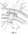
- FIG. 4 is a perspective view of the plate 24 and the tubular portion 31 viewed obliquely from above and is a partially enlarged view.
- FIG. 5 is a cross-sectional perspective view of the return filter 1 when viewed diagonally from below and is a partially enlarged view. In FIG. 5 , hatching for indicating a cross section is omitted.
- a hole 24e that opens to an end surface outward in a radial direction of the convex portion 24d is provided in the convex portion 24d along a longitudinal direction of the convex portion 24d.
- the IC tag 40 has a substantially cylindrical shape and is inserted into the inside of the hole 24e to be fixed. Thus, only an end surface 40a visible through the opening of the hole 24e of the IC tag 40 contacts the hydraulic oil. In this manner, avoiding the contact of the resin-coated IC tag 40 with the liquid as much as possible allows reducing a failure of the IC tag 40.
- the antenna assembly 50 is inserted into the hole 31a, which penetrates the side surface of the tubular portion 31, the antenna assembly 50 is inserted. An end surface 51a of the antenna 51 is exposed from the opening on the inner circumferential surface side of the hole 31a.
- the two projections 31b formed on the side surface of the tubular portion 31 serve as positioning of the filter element 20.
- the filter element 20 is inserted into the inside of the case 10 such that the convex portion 24d is disposed between the two projections 31b.
- the IC tag 40 and the antenna 51 are linearly arranged.
- the convex portion 24d protrudes upward from the plate-shaped portion 24a in side view and protrudes outward of the plate-shaped portion 24a in plan view, in the state where the filter element 20 is inserted into the inside of the case 10, the IC tag 40 is adjacent to the antenna 51, and the end surface 40a of the IC tag 40 is opposed to the end surface 51a of the antenna 51. Therefore, the IC tag 40 and the antenna 51 are disposed as close as possible, and thus sensing can be reliably performed.
- the dash-dotted line arrows in FIG. 2 indicate a flow of the hydraulic oil.
- the hydraulic oil starts flowing the inside of the hydraulic circuit.
- the hydraulic oil flows into the space S1 and the inside of the case 10 is filled with the hydraulic oil.
- the hydraulic oil flowing into the space S1 flows from the outside to the inside of the filter medium 21, and the filter medium 21 removes, for example, dust in the hydraulic oil.
- the hydraulic oil after filtration flows out to the space S2. After that, the hydraulic oil after filtration flows out from the outflow portion 12 to the space S3 (see FIG. 1 ).
- the filter element 20 Since the repeated filtration clogs the filter medium 21, the filter element 20 is replaced. Because the clogging of the filter medium 21 is substantially proportional to the operating time of the filter element 20, the operating time of the filter element 20 is measured by the IC tag 40, and the antenna 51 reads the IC tag 40 and transmits the operating time to the external device. When the operating time of the filter element 20 has elapsed for a certain period of time, the external device provides a display prompting replacement of the filter element 20. The filter element 20 after replacement is provided with the IC tag 40 different from that of the filter element 20 prior to the replacement, and the operating time of the filter element 20 after the replacement is measured by reading the IC tag 40.
- the external device can perform error display or disable the operation of the filter device. For example, by reading the IC tag 40 provided on the filter element 20 after the replacement, the external device can determine that a filter element other than the predetermined filter element is provided.
- the convex portion 24d is provided in the plate 24 and the IC tag 40 is provided inside the convex portion 24d, the contact between the IC tag 40 and the hydraulic oil is avoidable while the IC tag 40 is attached to the filter element 20. This allows reducing a failure of the IC tag 40.
- the plate 24 is made of resin and the antenna 51 is exposed from the opening on the inner circumferential surface side of the hole 31a, even when the lid body 30 is made of metal, recording information of the IC tag 40 can be accurately read. Furthermore, because the IC tag 40 is adjacent to the antenna 51, and the IC tag 40 and the antenna 51 are linearly arranged, the IC tag 40 and the antenna 51 can be disposed as close as possible, and the recording information of the IC tag 40 can be accurately read.
- the material of the plate 24 is not limited to the resin.
- the material of the plate 24 only needs to have high corrosion resistance, and may be, for example, a metal such as stainless steel. Since the end surface 40a is exposed from the plate 24, a failure does not occur in sensing.
- the second embodiment of the present invention is a configuration in which a plate-shaped IC tag is provided inside an adhesive that bonds the filter medium and the plate together.
- FIG. 6 is a cross-sectional perspective view of the return filter 2 when viewed diagonally from below and is a partially enlarged view. In FIG. 6 , hatching for indicating a cross section is omitted.
- the return filter 2 is provided inside the tank 100 and mainly includes the case 10, a filter element 20A, the lid body 30, an IC tag 40A, and the antenna assembly 50.
- the filter element 20A mainly includes the filter medium 21, the outer tube 22, the inner tube 23, a plate 24A, the plate 25 (not illustrated in FIG. 6 ), and the IC tag 40A.
- a difference between the plate 24 and the plate 24A is presence/absence of the convex portion 24d and the hole 24e, and the plate 24A does not have the convex portion 24d or the hole 24e.
- the adhesive 65 is sealed between the filter medium 21 and the plate 24A, and between the filter medium 21 and the plate 24A is bonded with the adhesive 65.
- the IC tag 40A is sealed in the adhesive 65.
- FIG. 7 is a plan view of the filter element 20A and is a drawing in which the plate 24A is partially cut off.
- the IC tag 40A has a substantially hollow circular plate shape.
- the IC tag 40A has an inner diameter greater than the inner diameter of the filter medium 21. Accordingly, the IC tag 40A can be provided inside the adhesive 65, which bonds the filter medium 21 and the plate 24 together.
- the IC tag 40A is provided inside the adhesive 65, which bonds the filter medium 21 and the plate 24A together, the contact between the IC tag 40A and the hydraulic oil is avoidable while the IC tag 40A is attached to the filter element 20A. This allows reducing a failure of the IC tag 40A.
- the IC tag 40A is embedded into the adhesive 65, which bonds the filter medium 21 and the plate 24A together, man-hours and cost for coating the IC tag 40A with resin can be reduced.
- the IC tag 40A has the substantially hollow circular plate shape, positioning of the IC tag 40A with the antenna 51 is unnecessary, and the assembly of the return filter 2 is easy.
- the plate 24A is made of the resin in the present embodiment, the plate 24A may be made of a metal. Even when the plate 24A is made of metal, the filter medium 21 side is not covered with the metal, and therefore the sensing is possible.
- the third embodiment of the present invention is a configuration in which a plate-shaped IC tag is provided inside an adhesive that bonds the filter medium and the plate together.
- a return filter 3 according to the third embodiment will be described below. Note that the same components as those in the first embodiment or the second embodiment are denoted by the same reference numerals, and descriptions thereof will be omitted.
- a difference between the return filter 2 according to the second embodiment and the return filter 3 according to the present embodiment is only a shape of the IC tag.
- the difference between return filter 3 and return filter 2 will be mainly described.
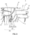
- FIG. 8 is a cross-sectional perspective view of the return filter 3 when viewed diagonally from below and is a partially enlarged view. In FIG. 8 , hatching for indicating a cross section is omitted.
- the return filter 3 is provided inside the tank 100 and mainly includes the case 10, a filter element 20B, the lid body 30, an IC tag 40B, and the antenna assembly 50.
- the filter element 20B mainly includes the filter medium 21, the outer tube 22, the inner tube 23, a plate 24B, the plate 25 (not illustrated in FIG. 8 ), and the IC tag 40B.
- a difference between the plate 24 and the plate 24B is presence/absence of the convex portion 24d and the hole 24e, and the plate 24B does not have the convex portion 24d or the hole 24e.
- a rib 24f is formed on a surface on an upper side of the plate-shaped portion 24a in the plate 24B. The rib 24f is formed during molding of the plate 24B and serves as a marking (described later).
- the adhesive 65 is sealed between the filter medium 21 and the plate 24B, and between the filter medium 21 and the plate 24B is bonded with the adhesive 65.
- the IC tag 40B is sealed in the adhesive 65.
- FIG. 9 is a plan view of the filter element 20B and is a drawing in which the plate 24B is partially cut off.
- the IC tag 40B has a substantially circular plate shape.
- the IC tag 40B has a diameter smaller than a width w of the filter medium 21. Accordingly, the IC tag 40B can be provided inside the adhesive that bonds the filter medium 21 and the plate 24B together.
- the IC tag 40B When the adhesive 65 is applied over the filter medium 21, the IC tag 40B is sealed in the adhesive 65, and after that, the plate 24B is placed on the adhesive 65. At this time, the rib 24f and the IC tag 40B are disposed so as to overlap in plan view.
- the filter element 20B When the filter element 20B is inserted into the inside of the case 10, the rib 24f and the antenna assembly 50 are disposed to be linearly arranged in plan view. As a result, the filter element 20B is provided in the internal space formed by the case 10 and the lid body 30 so that the IC tag 40B and the antenna 51 are linearly arranged.
- the IC tag 40B is provided inside the adhesive, which bonds the filter medium 21 and the plate 24B together, the contact between the IC tag 40B and the hydraulic oil is avoidable while the IC tag 40B is attached to the filter element 20B. This allows reducing a failure of the IC tag 40B.
- the IC tag 40B is embedded into the adhesive, which bonds the filter medium 21 and the plate 24B together, man-hours and cost for coating the IC tag 40B with resin can be reduced.
- the IC tag 40B has the substantially circular plate shape and has the diameter smaller than the width w of the filter medium 21, and therefore sealing the IC tag 40B in the adhesive is easy.
- the plate 24B is made of the resin in the present embodiment, the plate 24B may be made of a metal, similarly to the plate 24A. While one small IC tag 40B having the substantially circular plate shape is provided in the present embodiment, a plurality of the IC tags 40B may be provided. For example, the plurality of (four, six, eight, or the like) IC tags 40B may be radially provided.
- FIG. 10 is a schematic diagram of a filter element 20C according to a modified example in which the four IC tags 40B are radially provided.
- radially providing the plurality of IC tags 40B eliminates the need for matching the positions of the filter element 20 and the antenna 51.
- the rib 24f is unnecessary in the filter element 20C, the plate 24A in which the rib 24f is not formed can be used.
Landscapes
- Chemical & Material Sciences (AREA)
- Chemical Kinetics & Catalysis (AREA)
- Engineering & Computer Science (AREA)
- Computer Networks & Wireless Communication (AREA)
- Computer Hardware Design (AREA)
- Microelectronics & Electronic Packaging (AREA)
- Physics & Mathematics (AREA)
- General Physics & Mathematics (AREA)
- Theoretical Computer Science (AREA)
- Filtration Of Liquid (AREA)
- Fluid-Pressure Circuits (AREA)
Description
- The present invention relates to a filter device.
- For example, an apparatus that includes a hydraulic circuit, such as a construction machine, includes a filtration device in this hydraulic circuit.
JP 2008 290004 A -
WO 2005/113112 A andWO 2015/002307 A each disclose a filter device comprising an IC tag provided inside an upper plate of a filter element and an antenna provided on a lid body. -
WO 2014/203377 A discloses a filter device comprising an IC tag. The IC tag is embedded inside adhesive disposed between cover bodies of an identifying device disposed within a ditch. - In recent years, to reduce mounting of an imitation and management of an operating time and the like, attaching an IC tag to a filter element has been demanded. The IC tag immersed in liquid breaks easily. Therefore, when the IC tag is attached to a filter device, the IC tag preferably does not contact the liquid to avoid a failure of the IC tag. However, in the invention described in
JP 2008 290004 A - The present invention has been made in view of the circumstances, and an object of the present invention is to provide a filter device in which an IC tag is attached to a filter element and that allows avoiding the IC tag to contact liquid.
- The technical object is solved by the subject-matter of
claims - According to the subject-matter of
claim 1 according to the present invention, the IC tag is provided inside the upper plate provided so as to cover the upper end surface of the filter medium in the filter element. The lid body is provided on the case into which the filter element is inserted, and the antenna is provided on the lid body. Accordingly, the IC tag is attached to the filter element and a contact of the IC tag with liquid is avoidable. - Here, the upper plate includes a plate-shaped portion and a convex portion. The filter medium abuts on a lower side of the plate-shaped portion. The convex portion is provided in the plate-shaped portion. The IC tag is provided inside the convex portion. The lid body has two projections to position the convex portion in a circumferential direction. The antenna is provided in a vicinity of the two projections. With the filter element inserted into an inside of the case, the convex portion is adjacent to the two projections. As a result, the IC tag is adjacent to the antenna, and sensing becomes easy.
- Here, the convex portion may protrude upward from the plate-shaped portion in side view and protrude outward of the plate-shaped portion in plan view. With the filter element inserted into the inside of the case, an end surface of the IC tag may be opposed to an end surface of the antenna. As a result, the IC tag and the antenna are disposed at the nearest positions, and the sensing is reliably performed.
- A filter device according to
claim 3 of the present invention includes a case, a lid body, a filter element, an IC tag, and an antenna. The case has a substantially bottomed tubular shape with an open upper end. The lid body is provided on the case so as to cover the upper end of the case. The filter element has a substantially cylindrical shape provided in an internal space formed by the case and the lid body. The filter element includes a filter medium and an upper plate. The filter medium has a substantially cylindrical shape. The upper plate is provided so as to cover an upper end surface of the filter medium. The filter medium and the upper plate are bonded with an adhesive. The IC tag having a substantially plate shape is provided inside the adhesive. The antenna is provided on the lid body. Accordingly, the IC tag is attached to the filter element and the contact of the IC tag with liquid is avoidable. Furthermore, man-hours and cost for coating the IC tag with resin can be reduced. - Here, the IC tag may have a substantially hollow circular plate shape. The IC tag may have an inner diameter greater than an inner diameter of the filter medium. This eliminates a need for positioning the IC tag and the antenna and facilitates assembly of the filter device.
- Here, the IC tag may have a substantially circular plate shape. The filter element may be provided so that the IC tag and the antenna are linearly arranged. This facilitates sealing the IC tag in the adhesive.
- Here, the lid body may have a tubular portion having a substantially cylindrical shape. The tubular portion may have an inner diameter greater than an outer diameter of the upper plate. The tubular portion may have a through-hole that penetrates a side surface of the tubular portion. The antenna may be provided inside the through-hole. This allows mounting the antenna to an inside of the lid body. Moreover, the mounting of the antenna to the lid body is easy.
- With the present invention, the IC tag is attached to the filter element and the contact of the IC tag with liquid is avoidable.
-
-
FIG. 1 is a cross-sectional perspective view illustrating an overview of atank 100 in which areturn filter 1 according to one embodiment of the present invention is provided. -
FIG. 2 is a cross-sectional view illustrating an overview of thereturn filter 1. -
FIG. 3 is a plan view illustrating an overview of thereturn filter 1 and is a drawing illustrating a state in which a part of alid body 30 is removed. -
FIG. 4 is a perspective view of aplate 24 and atubular portion 31 viewed obliquely from above and is a partially enlarged view. -
FIG. 5 is a cross-sectional perspective view of thereturn filter 1 when viewed diagonally from below and is a partially enlarged view. -
FIG. 6 is a cross-sectional perspective view of areturn filter 2 and is a partially enlarged view. -
FIG. 7 is a plan view of afilter element 20A and is a drawing in which aplate 24A is partially cut off. -
FIG. 8 is a cross-sectional perspective view of areturn filter 3 and is a partially enlarged view. -
FIG. 9 is a plan view of afilter element 20B and is a drawing in which aplate 24B is partially cut off. -
FIG. 10 is a schematic diagram of afilter element 20C according to a modified example. - Hereinafter, with reference to the drawings, detailed description will be made on embodiments of the present invention. In the present embodiment, while hydraulic oil is described as an example of liquid to be filtered, the liquid to be filtered is not limited to the hydraulic oil. Also, while the following embodiments are described with an example of a return filter, a filter device of the present invention is not limited to the return filter.
-
FIG. 1 is a cross-sectional perspective view illustrating an overview of atank 100 in which areturn filter 1 according to one embodiment of the present invention is provided. InFIG. 1 , hatching for indicating a cross section is omitted. - The
tank 100 is a tank for storing hydraulic oil. Thetank 100 is installed in a work machine (not illustrated) (e.g., a hydraulic device), and is provided in a hydraulic circuit of hydraulic oil supplied to the hydraulic device. However, thetank 100 is not limited to one provided in the hydraulic circuit. - The
tank 100 is, for example, formed in a box-like shape and hollow inside. Thetank 100 mainly has abottom surface 101, atop surface 102 opposed to thebottom surface 101, andside surfaces 103 substantially orthogonal to thebottom surface 101 and thetop surface 102. Anopening 102a (seeFIG. 2 ) is formed in thetop surface 102. Thereturn filter 1 is inserted into an inside of thetank 100 from theopening 102a. Theopening 102a is covered with a lid body 30 (described in detail later) of thereturn filter 1. - An inflow portion (not illustrated) that causes the hydraulic oil to flow into the inside of the
return filter 1 is inserted through theside surface 103. The inflow portion introduces the hydraulic oil from an outside of thetank 100 to thereturn filter 1. The hydraulic oil introduced into thereturn filter 1 is filtered by thereturn filter 1 and stored in thetank 100. - An outflow port (not illustrated) that causes the hydraulic oil in the
tank 100 to flow out to, for example, a hydraulic pump (not illustrated) is formed in the vicinity of thebottom surface 101. A suction strainer 9 is provided inside thetank 100. The hydraulic oil that has passed through the suction strainer 9 flows out from the outflow port to the outside of thetank 100. - A
partition plate 105 is provided inside thetank 100 such that the hydraulic oil that has flown out from thereturn filter 1 does not directly contact the suction strainer 9. Note that thepartition plate 105 is not necessarily required. - Next, the
return filter 1 will be described.FIG. 2 is a cross-sectional view illustrating an overview of thereturn filter 1. InFIG. 2 , hatching for indicating a cross section is omitted, and illustration of a part on the -x side with respect to the center line is omitted.FIG. 3 is a plan view illustrating an overview of thereturn filter 1 and is a drawing illustrating a state in which a part of thelid body 30 is removed. - The
return filter 1 mainly includes acase 10, afilter element 20, thelid body 30, anIC tag 40, and anantenna assembly 50. TheIC tag 40 is a small electronic component that contactlessly reads and writes data in a built-in memory using radio waves received from an antenna 51 (described below). Theantenna 51 is connected to an external device and receives radio waves from theIC tag 40. - The
case 10 is made of a metal having high corrosion resistance (for example, stainless steel). Thecase 10 is provided inside thetank 100 so as to protrude from thetop surface 102 of thetank 100 to a lower side (-z-side) (see -
FIG. 1 ). - The
case 10 has a bottomed substantially tubular shape and has an open upper end surface. Thecase 10 is hollow inside and internally includes, for example, thefilter element 20. - The
case 10 has abottom surface 11. Anoutflow portion 12 is provided so as to penetrate thebottom surface 11. Theoutflow portion 12 communicates between a space inside the filter element 20 (space S2) and a space outside the case 10 (space S3, seeFIG. 1 ). - A mounting
member 13 is provided in the vicinity of an upper end of thecase 10. Thecase 10 is provided in thetank 100 via the mountingmember 13. Furthermore, the mountingmember 13 integrates thecase 10 and a tubular portion 31 (described in detail later). - The inflow portion (not illustrated) is provided on a side surface of the
case 10. The inflow portion communicates between a space inside thecase 10 and outside the filter element 20 (space S1) and the space outside thecase 10 and inside the tank 100 (space S3, seeFIG. 1 ). An inflow of the hydraulic oil from the inflow portion stores the hydraulic oil in thecase 10. - The
filter element 20 is a member having a bottomed substantially tubular shape and provided in an internal space formed by thecase 10 and thelid body 30. Thefilter element 20 mainly includes afilter medium 21, anouter tube 22, aninner tube 23, aplate 24, aplate 25, and theIC tag 40. Theouter tube 22, theinner tube 23, and theplates filter medium 21. - The
filter medium 21 is a member having a substantially cylindrical shape and having openings at both ends. Thefilter medium 21 is formed by pleating a filter paper using, for example, synthetic resin or a paper, and connecting both ends of the pleated filter paper to form a cylindrical shape. Theinner tube 23 where holes through which the hydraulic oil passes are formed in a substantially entire area is provided inside thefilter medium 21. - The
outer tube 22 is provided on an outer side of thefilter medium 21, and theinner tube 23 is provided on an inner side of thefilter medium 21. Holes (not illustrated) through which the hydraulic oil passes are provided on entire surfaces of theouter tube 22 and theinner tube 23. - The
plate 24 made of resin is provided on an end on the upper side of thefilter medium 21. Theplate 24 covers upper end surfaces of thefilter medium 21, theouter tube 22, and theinner tube 23. An adhesive 65 is applied between theplate 24 and thefilter medium 21, and between theplate 24 and thefilter medium 21 is bonded with the adhesive 65. Although the adhesive 65 is liquid when applied, the adhesive 65 hardens over time to bond theplate 24 and thefilter medium 21 together. Here, various types of organic adhesives using resin, rubber, and elastomer as the main material can be used as the adhesive 65. Furthermore, the adhesive 65 may contain powder, such as silicon dioxide. - The
plate 24 mainly includes a plate-shapedportion 24a having a substantially circular plate shape provided along an upper end surface of thefilter medium 21 such that thefilter medium 21 abuts on a lower side of the plate-shapedportion 24a, atubular portion 24b provided on outer peripheral edge of the plate-shapedportion 24a, atubular portion 24c provided on an inner peripheral edge of the plate-shapedportion 24a, and aconvex portion 24d provided in the plate-shapedportion 24a. Thetubular portion 24b protrudes downward (in the -z direction) from the plate-shapedportion 24a. Thetubular portion 24c protrudes upward (in the +z direction) from the plate-shapedportion 24a. - The
convex portion 24d protrudes upward from the plate-shapedportion 24a in side view (here, as illustrated inFIG. 2 , when viewed from the y direction). Additionally, theconvex portion 24d protrudes outward of the plate-shapedportion 24a in plan view (here, as illustrated inFIG. 3 , when viewed from the z-direction). - The
IC tag 40 is coated with resin. TheIC tag 40 is provided inside theplate 24 so as to not contact the hydraulic oil. In the present embodiment, theIC tag 40 is provided inside theconvex portion 24d. - The
plate 25 is provided on an end on the lower side of thefilter medium 21. Theplate 25 is a member having a substantially hollow circular plate shape that covers lower end surfaces of thefilter medium 21, theouter tube 22, and theinner tube 23. A recessed portion 25a into which thefilter medium 21 is inserted is formed in a surface of the upper side of theplate 25. The adhesive 65 is applied between the recessed portion 25a and thefilter medium 21, and the recessed portion 25a and thefilter medium 21 are bonded with the adhesive 65. - The
outflow portion 12 is inserted into ahole 25b formed in the substantially center of theplate 25. Thehole 25b and theoutflow portion 12 are sealed by a sealing member (for example, an O-ring) 61. - The
lid body 30 is provided on an outer side of thetank 100. Thelid body 30 is provided on the case 10 (here, the mounting member 13) and the plate 24 (here, thetubular portion 24c) so as to cover the opening of the upper end surface of thecase 10. - The
lid body 30 is made of a metal having high corrosion resistance (for example, stainless steel). Thelid body 30 mainly includes thetubular portion 31, acover 32, and a mountingportion 33. Thetubular portion 31 has a substantially cylindrical shape and is fixed to the case 10 (here, the mounting member 13). Thecover 32 is a substantially plate-shaped member and provided on the upper side (+z-side) of thetubular portion 31 so as to cover a hollow portion of thetubular portion 31. Thecover 32 is detachably provided to thetubular portion 31. - The
tubular portion 31 has an inner diameter greater than an outer diameter of theplate 24. Thetubular portion 31 has a side surface on which ahole 31a penetrating the side surface is provided. Theantenna assembly 50 is inserted into thehole 31a to fix (for example, screw) theantenna assembly 50, and thus theantenna assembly 50 is provided in thetubular portion 31. Theantenna assembly 50 includes theantenna 51. Accordingly, theantenna 51 can be easily mounted to the inside of thelid body 30. - Two
projections 31b (seeFIG. 3 ) are formed in the side surface of thetubular portion 31. Theprojections 31b are formed so as to protrude inward in an inner circumferential surface of thetubular portion 31. Theprojections 31b are formed in the vicinity of thehole 31a, here, on both sides of thehole 31a. That is, theantenna 51 is provided in the vicinity of theprojections 31b. - The
projections 31b position theconvex portion 24d in the circumferential direction. Theconvex portion 24d is disposed between the twoprojections 31b. In other words, in a state where thefilter element 20 is inserted into the inside of thecase 10, theconvex portion 24d is adjacent to theprojections 31b. Note that theconvex portion 24d may abut on theprojection 31b. - The mounting
portion 33 is provided on thecover 32. The mountingportion 33 is a substantially tubular member, and protrudes to the lower side (-z-side) of thecover 32. Avalve 63 is provided on a lower side of the mountingportion 33. Thevalve 63 is usually closed. When thefilter medium 21 becomes clogged and the pressure inside thecase 10 increases, thevalve 63 opens to flow the hydraulic oil from the space S1 to the space S2 to reduce a breakage of thereturn filter 1. Thevalve 63 is already well known, and thus the description is omitted. - The mounting
portion 33 is inserted into thetubular portion 24c, and thevalve 63 is inserted into the space S2. The mountingportion 33 and thetubular portion 24c are sealed by a sealing member (for example, an O-ring) 62. - Next, the attachment and disposition of the
IC tag 40 and theantenna assembly 50 will be described.FIG. 4 is a perspective view of theplate 24 and thetubular portion 31 viewed obliquely from above and is a partially enlarged view.FIG. 5 is a cross-sectional perspective view of thereturn filter 1 when viewed diagonally from below and is a partially enlarged view. InFIG. 5 , hatching for indicating a cross section is omitted. - A
hole 24e that opens to an end surface outward in a radial direction of theconvex portion 24d is provided in theconvex portion 24d along a longitudinal direction of theconvex portion 24d. TheIC tag 40 has a substantially cylindrical shape and is inserted into the inside of thehole 24e to be fixed. Thus, only anend surface 40a visible through the opening of thehole 24e of theIC tag 40 contacts the hydraulic oil. In this manner, avoiding the contact of the resin-coatedIC tag 40 with the liquid as much as possible allows reducing a failure of theIC tag 40. - Note that, after the
IC tag 40 is inserted into thehole 24e, covering the opening of thehole 24e with resin or the like allows avoiding theIC tag 40 to contact the liquid completely. - Into the
hole 31a, which penetrates the side surface of thetubular portion 31, theantenna assembly 50 is inserted. Anend surface 51a of theantenna 51 is exposed from the opening on the inner circumferential surface side of thehole 31a. - The two
projections 31b formed on the side surface of thetubular portion 31 serve as positioning of thefilter element 20. Thefilter element 20 is inserted into the inside of thecase 10 such that theconvex portion 24d is disposed between the twoprojections 31b. As a result, theIC tag 40 and theantenna 51 are linearly arranged. In addition, because theconvex portion 24d protrudes upward from the plate-shapedportion 24a in side view and protrudes outward of the plate-shapedportion 24a in plan view, in the state where thefilter element 20 is inserted into the inside of thecase 10, theIC tag 40 is adjacent to theantenna 51, and theend surface 40a of theIC tag 40 is opposed to theend surface 51a of theantenna 51. Therefore, theIC tag 40 and theantenna 51 are disposed as close as possible, and thus sensing can be reliably performed. - Next, the functionality of the
return filter 1 thus configured will be described. The dash-dotted line arrows inFIG. 2 indicate a flow of the hydraulic oil. For example, when the work machine starts driving, the hydraulic oil starts flowing the inside of the hydraulic circuit. In association with this, the hydraulic oil flows into the space S1 and the inside of thecase 10 is filled with the hydraulic oil. - The hydraulic oil flowing into the space S1 flows from the outside to the inside of the
filter medium 21, and thefilter medium 21 removes, for example, dust in the hydraulic oil. The hydraulic oil after filtration flows out to the space S2. After that, the hydraulic oil after filtration flows out from theoutflow portion 12 to the space S3 (seeFIG. 1 ). - Since the repeated filtration clogs the
filter medium 21, thefilter element 20 is replaced. Because the clogging of thefilter medium 21 is substantially proportional to the operating time of thefilter element 20, the operating time of thefilter element 20 is measured by theIC tag 40, and theantenna 51 reads theIC tag 40 and transmits the operating time to the external device. When the operating time of thefilter element 20 has elapsed for a certain period of time, the external device provides a display prompting replacement of thefilter element 20. Thefilter element 20 after replacement is provided with theIC tag 40 different from that of thefilter element 20 prior to the replacement, and the operating time of thefilter element 20 after the replacement is measured by reading theIC tag 40. In addition, when an imitation or the like in which theIC tag 40 is not provided is used as the filter element after replacement, needless to say, theIC tag 40 cannot be read. The external device can perform error display or disable the operation of the filter device. For example, by reading theIC tag 40 provided on thefilter element 20 after the replacement, the external device can determine that a filter element other than the predetermined filter element is provided. - With the present embodiment, because the
convex portion 24d is provided in theplate 24 and theIC tag 40 is provided inside theconvex portion 24d, the contact between theIC tag 40 and the hydraulic oil is avoidable while theIC tag 40 is attached to thefilter element 20. This allows reducing a failure of theIC tag 40. - In addition, with the present embodiment, because the
plate 24 is made of resin and theantenna 51 is exposed from the opening on the inner circumferential surface side of thehole 31a, even when thelid body 30 is made of metal, recording information of theIC tag 40 can be accurately read. Furthermore, because theIC tag 40 is adjacent to theantenna 51, and theIC tag 40 and theantenna 51 are linearly arranged, theIC tag 40 and theantenna 51 can be disposed as close as possible, and the recording information of theIC tag 40 can be accurately read. - Note that, although the
plate 24 is made of the resin in the present embodiment, the material of theplate 24 is not limited to the resin. The material of theplate 24 only needs to have high corrosion resistance, and may be, for example, a metal such as stainless steel. Since theend surface 40a is exposed from theplate 24, a failure does not occur in sensing. - The second embodiment of the present invention is a configuration in which a plate-shaped IC tag is provided inside an adhesive that bonds the filter medium and the plate together. Below, description is given of a
return filter 2 according to the second embodiment. Note that the same components as those in the first embodiment are denoted by the same reference numerals, and descriptions thereof will be omitted. -
FIG. 6 is a cross-sectional perspective view of thereturn filter 2 when viewed diagonally from below and is a partially enlarged view. InFIG. 6 , hatching for indicating a cross section is omitted. - The
return filter 2 is provided inside thetank 100 and mainly includes thecase 10, afilter element 20A, thelid body 30, anIC tag 40A, and theantenna assembly 50. - The
filter element 20A mainly includes thefilter medium 21, theouter tube 22, theinner tube 23, aplate 24A, the plate 25 (not illustrated inFIG. 6 ), and theIC tag 40A. A difference between theplate 24 and theplate 24A is presence/absence of theconvex portion 24d and thehole 24e, and theplate 24A does not have theconvex portion 24d or thehole 24e. - The adhesive 65 is sealed between the
filter medium 21 and theplate 24A, and between thefilter medium 21 and theplate 24A is bonded with the adhesive 65. TheIC tag 40A is sealed in the adhesive 65. -
FIG. 7 is a plan view of thefilter element 20A and is a drawing in which theplate 24A is partially cut off. - The
IC tag 40A has a substantially hollow circular plate shape. TheIC tag 40A has an inner diameter greater than the inner diameter of thefilter medium 21. Accordingly, theIC tag 40A can be provided inside the adhesive 65, which bonds thefilter medium 21 and theplate 24 together. - With the present embodiment, because the
IC tag 40A is provided inside the adhesive 65, which bonds thefilter medium 21 and theplate 24A together, the contact between theIC tag 40A and the hydraulic oil is avoidable while theIC tag 40A is attached to thefilter element 20A. This allows reducing a failure of theIC tag 40A. - In addition, with the present embodiment, because the
IC tag 40A is embedded into the adhesive 65, which bonds thefilter medium 21 and theplate 24A together, man-hours and cost for coating theIC tag 40A with resin can be reduced. - In addition, with the present embodiment, because the
IC tag 40A has the substantially hollow circular plate shape, positioning of theIC tag 40A with theantenna 51 is unnecessary, and the assembly of thereturn filter 2 is easy. - Note that, although the
plate 24A is made of the resin in the present embodiment, theplate 24A may be made of a metal. Even when theplate 24A is made of metal, thefilter medium 21 side is not covered with the metal, and therefore the sensing is possible. - The third embodiment of the present invention, similar to the second embodiment, is a configuration in which a plate-shaped IC tag is provided inside an adhesive that bonds the filter medium and the plate together. A
return filter 3 according to the third embodiment will be described below. Note that the same components as those in the first embodiment or the second embodiment are denoted by the same reference numerals, and descriptions thereof will be omitted. - A difference between the
return filter 2 according to the second embodiment and thereturn filter 3 according to the present embodiment is only a shape of the IC tag. The difference betweenreturn filter 3 and returnfilter 2 will be mainly described. -
FIG. 8 is a cross-sectional perspective view of thereturn filter 3 when viewed diagonally from below and is a partially enlarged view. InFIG. 8 , hatching for indicating a cross section is omitted. - The
return filter 3 is provided inside thetank 100 and mainly includes thecase 10, afilter element 20B, thelid body 30, anIC tag 40B, and theantenna assembly 50. - The
filter element 20B mainly includes thefilter medium 21, theouter tube 22, theinner tube 23, aplate 24B, the plate 25 (not illustrated inFIG. 8 ), and theIC tag 40B. A difference between theplate 24 and theplate 24B is presence/absence of theconvex portion 24d and thehole 24e, and theplate 24B does not have theconvex portion 24d or thehole 24e. In addition, arib 24f is formed on a surface on an upper side of the plate-shapedportion 24a in theplate 24B. Therib 24f is formed during molding of theplate 24B and serves as a marking (described later). - The adhesive 65 is sealed between the
filter medium 21 and theplate 24B, and between thefilter medium 21 and theplate 24B is bonded with the adhesive 65. TheIC tag 40B is sealed in the adhesive 65. -
FIG. 9 is a plan view of thefilter element 20B and is a drawing in which theplate 24B is partially cut off. - The
IC tag 40B has a substantially circular plate shape. TheIC tag 40B has a diameter smaller than a width w of thefilter medium 21. Accordingly, theIC tag 40B can be provided inside the adhesive that bonds thefilter medium 21 and theplate 24B together. - When the adhesive 65 is applied over the
filter medium 21, theIC tag 40B is sealed in the adhesive 65, and after that, theplate 24B is placed on the adhesive 65. At this time, therib 24f and theIC tag 40B are disposed so as to overlap in plan view. When thefilter element 20B is inserted into the inside of thecase 10, therib 24f and theantenna assembly 50 are disposed to be linearly arranged in plan view. As a result, thefilter element 20B is provided in the internal space formed by thecase 10 and thelid body 30 so that theIC tag 40B and theantenna 51 are linearly arranged. - With the present embodiment, because the
IC tag 40B is provided inside the adhesive, which bonds thefilter medium 21 and theplate 24B together, the contact between theIC tag 40B and the hydraulic oil is avoidable while theIC tag 40B is attached to thefilter element 20B. This allows reducing a failure of theIC tag 40B. In addition, because theIC tag 40B is embedded into the adhesive, which bonds thefilter medium 21 and theplate 24B together, man-hours and cost for coating theIC tag 40B with resin can be reduced. - In addition, with the present embodiment, the
IC tag 40B has the substantially circular plate shape and has the diameter smaller than the width w of thefilter medium 21, and therefore sealing theIC tag 40B in the adhesive is easy. - Note that, although the
plate 24B is made of the resin in the present embodiment, theplate 24B may be made of a metal, similarly to theplate 24A. While onesmall IC tag 40B having the substantially circular plate shape is provided in the present embodiment, a plurality of the IC tags 40B may be provided. For example, the plurality of (four, six, eight, or the like) IC tags 40B may be radially provided.FIG. 10 is a schematic diagram of afilter element 20C according to a modified example in which the fourIC tags 40B are radially provided. Thus radially providing the plurality ofIC tags 40B eliminates the need for matching the positions of thefilter element 20 and theantenna 51. In addition, since therib 24f is unnecessary in thefilter element 20C, theplate 24A in which therib 24f is not formed can be used. -
- 1, 2, 3 Return filter
- 9 Suction strainer
- 10 Case
- 11 Bottom surface
- 12 Outflow portion
- 13 Mounting member
- 20, 20A, 20B, 20C Filter element
- 21 Filter medium
- 22 Outer tube
- 23 Inner tube
- 24, 24A, 24B Plate
- 24a plate-shaped portion
- 24b Tubular portion
- 24c Tubular portion
- 24d Convex portion
- 24e Hole
- 24f Rib
- 25 Plate
- 25a Recessed portion
- 25b Hole
- 30 Lid body
- 31 Tubular portion
- 31a Hole
- 31b Projection
- 32 Cover
- 33 Mounting portion
- 40, 40A, 40B IC tag
- 40a End surface
- 50 Antenna assembly
- 51 Antenna
- 51a End surface
- 61, 62 Sealing member
- 63 Valve
- 65 Adhesive
- 100 Tank
- 101 Bottom surface
- 102 Top surface
- 102a Opening
- 103 Side surface
- 105 Partition plate
Claims (6)
- A filter device (1), comprising:a case (10) having a bottomed tubular shape with an open upper end;a lid body (30) provided on the case (10) so as to cover the upper end of the case (10);a filter element (20) having a cylindrical shape provided in an internal space formed by the case (10) and the lid body (30), the filter element (20) including a filter medium (21) and an upper plate (24), the filter medium (21) having a cylindrical shape, the upper plate (24) being provided so as to cover an upper end surface of the filter medium (21);an IC tag (40) provided inside the upper plate (24); andan antenna (51) provided on the lid body (30), whereinthe upper plate (24) includes a plate-shaped portion (24a) and the filter medium (21) abuts on a lower side of the plate-shaped portion (24a),characterised in thatthe upper plate (24) further includes a convex portion (24d), and the convex portion (24d) is provided in the plate-shaped portion (24a),the IC tag (40) is provided inside the convex portion (24d),the lid body (30) has two projections (31b) to position the convex portion (24d) in a circumferential direction,the antenna (51) is provided in a vicinity of the two projections (31b), andwith the filter element (20) inserted into an inside of the case (10), the convex portion (24d) is adjacent to the two projections (31b), the convex portion (24d) being disposed between the two projections (31b),the IC tag (40) and the antenna (51) are linearly arranged along a longitudinal direction of the convex portion (24d),the IC tag (40) is adjacent to the antenna (51) along the longitudinal direction of the convex portion (24d), andan end surface (40a) of the IC tag (40) is opposed to an end surface (51a) of the antenna (51) along the longitudinal direction of the convex portion (24d).
- The filter device (1) according to claim 1, whereinthe convex portion (24d) protrudes upward from the plate-shaped portion (24a) in side view and protrudes outward of the plate-shaped portion (24a) in plan view, andwith the filter element (20) inserted into the inside of the case (10), an end surface of the IC tag (40) is opposed to an end surface of the antenna (51).
- A filter device (2; 3), comprising:a case (10) having a bottomed tubular shape with an open upper end;a lid body (30) provided on the case (10) so as to cover the upper end of the case (10); anda filter element (20A; 20B; 20C) having a cylindrical shape provided in an internal space formed by the case (10) and the lid body (30), the filter element (20A; 20B; 20C) including a filter medium (21) and an upper plate (24), the filter medium (21) having a cylindrical shape, the upper plate (24) being provided so as to cover an upper end surface of the filter medium (21), characterised in thatthe filter medium (21) and the upper plate (24) are bonded with an adhesive (65), andthe filter divece (2; 3) further comprises:an IC tag (40A; 40B) having a plate shape provided inside the adhesive (65); andan antenna (51) provided on the lid body (30).
- The filter device (2; 3) according to claim 3, whereinthe IC tag (40A) has a hollow circular plate shape, andthe IC tag (40A) has an inner diameter greater than an inner diameter of the filter medium (21).
- The filter device (3) according to claim 3, whereinthe IC tag (40B) has a circular plate shape, andthe filter element (20B; 20C) is provided so that the IC tag (40B) and the antenna (51) are linearly arranged.
- The filter device (1; 2; 3) according to any one of claims 1 to 5, whereinthe lid body (30) has a tubular portion (31) having a cylindrical shape,the tubular portion (31) has an inner diameter greater than an outer diameter of the upper plate (24),the tubular portion (31) has a through-hole (31a) that penetrates a side surface of the tubular portion (31), andthe antenna (51) is provided inside the through-hole (31a).
Applications Claiming Priority (2)
| Application Number | Priority Date | Filing Date | Title |
|---|---|---|---|
| JP2017250185A JP7082874B2 (en) | 2017-12-26 | 2017-12-26 | Filter device |
| PCT/JP2018/046284 WO2019131263A1 (en) | 2017-12-26 | 2018-12-17 | Filter device |
Publications (3)
| Publication Number | Publication Date |
|---|---|
| EP3733259A1 EP3733259A1 (en) | 2020-11-04 |
| EP3733259A4 EP3733259A4 (en) | 2021-02-17 |
| EP3733259B1 true EP3733259B1 (en) | 2023-03-22 |
Family
ID=67063583
Family Applications (1)
| Application Number | Title | Priority Date | Filing Date |
|---|---|---|---|
| EP18894233.8A Active EP3733259B1 (en) | 2017-12-26 | 2018-12-17 | Filter device |
Country Status (6)
| Country | Link |
|---|---|
| US (1) | US11406920B2 (en) |
| EP (1) | EP3733259B1 (en) |
| JP (1) | JP7082874B2 (en) |
| KR (1) | KR102724232B1 (en) |
| CN (1) | CN111372667B (en) |
| WO (1) | WO2019131263A1 (en) |
Families Citing this family (7)
| Publication number | Priority date | Publication date | Assignee | Title |
|---|---|---|---|---|
| JP7431556B2 (en) | 2019-11-06 | 2024-02-15 | ヤマシンフィルタ株式会社 | Measuring unit and filter device |
| JP7305518B2 (en) * | 2019-11-08 | 2023-07-10 | ヤマシンフィルタ株式会社 | filter device |
| CN114692803B (en) * | 2020-12-31 | 2026-07-24 | 上海索菲玛汽车滤清器有限公司 | Functional components, modules, and mounting bases with NFC tags |
| JP7827470B2 (en) * | 2022-01-27 | 2026-03-10 | ヤマシンフィルタ株式会社 | Filter Device |
| JP2024119693A (en) * | 2023-02-22 | 2024-09-03 | ヤマシンフィルタ株式会社 | Filter Device |
| DE102023001705A1 (en) * | 2023-04-27 | 2024-10-31 | Hydac Filtertechnik Gmbh | filter device |
| US12611224B2 (en) * | 2024-02-14 | 2026-04-28 | Penumbra, Inc. | Vascular occlusion detection from motorized separator torque measurement signal |
Family Cites Families (47)
| Publication number | Priority date | Publication date | Assignee | Title |
|---|---|---|---|---|
| DE2323228A1 (en) * | 1973-05-09 | 1974-11-21 | Netzsch Maschinenfabrik | DEVICE FOR MUTUAL SUPPORTING OF FILTER PLATES |
| DE4030304C2 (en) * | 1990-09-25 | 1994-10-27 | Hermann Trabold | Filters for filtering gaseous and liquid media |
| JP2929424B2 (en) * | 1994-12-26 | 1999-08-03 | 明禹 全 | Fluid filtration device |
| JPH09285414A (en) * | 1996-04-23 | 1997-11-04 | Janome Sewing Mach Co Ltd | Bath water purifier |
| KR20020082787A (en) * | 2001-04-25 | 2002-10-31 | 소니 가부시끼 가이샤 | Communication module and communication apparatus having such a communication module |
| DE10207633B4 (en) * | 2002-02-22 | 2006-12-14 | K & H. Eppensteiner Gmbh Filterbau | filter |
| KR100895567B1 (en) * | 2003-12-05 | 2009-04-29 | 히다치 가세고교 가부시끼가이샤 | Electronic device manufacturing method |
| US20050161378A1 (en) * | 2004-01-23 | 2005-07-28 | Cline L. S. | Two piece elastomer relief and anti-drain back valves for filter |
| JP4504694B2 (en) * | 2004-01-30 | 2010-07-14 | トッパン・フォームズ株式会社 | Thread manufacturing method, IC chip-containing sheet manufacturing method, and thread and IC chip-containing sheet manufactured thereby |
| JP2007537870A (en) * | 2004-05-20 | 2007-12-27 | ドナルドソン カンパニー,インコーポレイティド | Filter assembly having an antenna |
| CN100563779C (en) * | 2004-06-29 | 2009-12-02 | 唐纳森公司 | Liquid filter structure and method |
| CN101068722A (en) * | 2004-09-29 | 2007-11-07 | 关卡系统股份有限公司 | Method and system for tracking containers and container closures having metal parts, labels for use with containers having metal parts, and methods of marking such labels |
| JP2007069722A (en) * | 2005-09-06 | 2007-03-22 | Nippon Sheet Glass Co Ltd | Window for vehicle, and mounting structure of electronic tag |
| JP2007233756A (en) * | 2006-03-01 | 2007-09-13 | Nippon Sheet Glass Co Ltd | Ic tag sheet |
| CN101520356A (en) * | 2006-06-26 | 2009-09-02 | 阮志成 | Pressure sensing device for insulated integrated circuit |
| DE102006034943A1 (en) * | 2006-07-28 | 2008-01-31 | Hydac Filtertechnik Gmbh | Filter system for fluids |
| US7811365B2 (en) * | 2006-10-16 | 2010-10-12 | Millipore Corporation | Wireless receptor for communications within housings |
| US7850893B2 (en) * | 2006-12-01 | 2010-12-14 | Rexam Healthcare Packaging Inc. | Molded plastic container and preform having insert-molded RFID tag |
| JP5063406B2 (en) * | 2007-03-22 | 2012-10-31 | 東洋製罐株式会社 | Plastic cap with IC tag |
| JP2008247418A (en) * | 2007-03-30 | 2008-10-16 | Ckd Corp | PTP sheet and PTP packaging machine |
| JP5074146B2 (en) * | 2007-03-30 | 2012-11-14 | オリンパス株式会社 | Capsule medical device |
| JP4892407B2 (en) | 2007-05-24 | 2012-03-07 | ヤマシンフィルタ株式会社 | Filtration equipment, tank equipment |
| KR20080111324A (en) * | 2007-06-18 | 2008-12-23 | 주식회사 알카메디 | Water purifier filter activation method and device |
| DE102007062102A1 (en) * | 2007-12-21 | 2009-06-25 | Mahle International Gmbh | filtering device |
| DE102008009242A1 (en) * | 2008-02-07 | 2009-08-13 | Hydac Filtertechnik Gmbh | Filter element and filter device with such a filter element |
| US7898495B2 (en) * | 2008-03-26 | 2011-03-01 | Millipore Corporation | Antenna gasket for process housing |
| CN102785828B (en) * | 2008-06-20 | 2015-04-29 | 东洋制罐株式会社 | Resin overcap provided with ic tag |
| CN102724946B (en) * | 2009-07-29 | 2015-06-10 | Icu医学有限公司 | Fluid transfer device and method of use |
| JP4913894B2 (en) * | 2010-08-25 | 2012-04-11 | 株式会社フジシールインターナショナル | Container with IC tag and package with IC tag |
| JP2012241657A (en) | 2011-05-23 | 2012-12-10 | Denso Corp | Fuel filter diagnostic system and filter cartridge |
| WO2014002971A1 (en) * | 2012-06-25 | 2014-01-03 | 東洋製罐グループホールディングス株式会社 | Ic tagged compound container lid |
| JP5607132B2 (en) * | 2012-11-19 | 2014-10-15 | 株式会社小松製作所 | Filter with IC tag and IC tag for filter |
| GB201301188D0 (en) * | 2013-01-23 | 2013-03-06 | Cryogatt Systems Ltd | RFID tag |
| CN104138681B (en) * | 2013-05-10 | 2016-05-11 | 雅玛信过滤器株式会社 | Filter core unit |
| WO2014203377A1 (en) * | 2013-06-20 | 2014-12-24 | 株式会社小松製作所 | Filter, and working vehicle provided with filter |
| JP6126921B2 (en) * | 2013-07-04 | 2017-05-10 | 和興フィルタテクノロジー株式会社 | Liquid filter device, filter element and filter cartridge |
| JP6165574B2 (en) * | 2013-09-26 | 2017-07-19 | シスメックス株式会社 | Filter member and cell acquisition method |
| CN204147622U (en) * | 2014-06-03 | 2015-02-11 | 雅玛信过滤器株式会社 | Filter core and filter |
| JP2016018431A (en) * | 2014-07-09 | 2016-02-01 | Dowaエレクトロニクス株式会社 | Rfid tag substrate using paper substrate and rfid tag |
| CN104496055A (en) * | 2014-12-08 | 2015-04-08 | 佛山市顺德区阿波罗环保器材有限公司 | Anti-counterfeiting water purifying device based on filter element recognition |
| DE102015003604A1 (en) * | 2015-03-19 | 2016-09-22 | Hydac Filtertechnik Gmbh | filter means |
| FI20155527A7 (en) * | 2015-07-03 | 2017-01-04 | Outotec Finland Oy | Filter apparatus and method |
| CN105233557A (en) * | 2015-10-13 | 2016-01-13 | 北京四季沐歌太阳能技术集团有限公司 | Water purification equipment with filter core management module and control method thereof |
| US10286343B2 (en) | 2016-10-28 | 2019-05-14 | Pall Corporation | Filter including RFID tag |
| DE102017004174A1 (en) * | 2017-04-27 | 2018-10-31 | Rt-Filtertechnik Gmbh | filter means |
| CN107261615A (en) * | 2017-06-08 | 2017-10-20 | 厦门百霖净水科技有限公司 | A kind of intelligent filter core and intelligent water purification device |
| DE202019005615U1 (en) * | 2018-09-05 | 2021-03-12 | Atlas Copco Airpower, N.V. | filter |
-
2017
- 2017-12-26 JP JP2017250185A patent/JP7082874B2/en active Active
-
2018
- 2018-12-17 WO PCT/JP2018/046284 patent/WO2019131263A1/en not_active Ceased
- 2018-12-17 CN CN201880075176.XA patent/CN111372667B/en active Active
- 2018-12-17 KR KR1020207014409A patent/KR102724232B1/en active Active
- 2018-12-17 EP EP18894233.8A patent/EP3733259B1/en active Active
-
2020
- 2020-06-10 US US16/897,931 patent/US11406920B2/en active Active
Also Published As
| Publication number | Publication date |
|---|---|
| CN111372667A (en) | 2020-07-03 |
| US11406920B2 (en) | 2022-08-09 |
| JP2019115879A (en) | 2019-07-18 |
| KR20200096218A (en) | 2020-08-11 |
| EP3733259A1 (en) | 2020-11-04 |
| US20200298148A1 (en) | 2020-09-24 |
| EP3733259A4 (en) | 2021-02-17 |
| WO2019131263A1 (en) | 2019-07-04 |
| CN111372667B (en) | 2022-06-10 |
| JP7082874B2 (en) | 2022-06-09 |
| KR102724232B1 (en) | 2024-10-30 |
Similar Documents
| Publication | Publication Date | Title |
|---|---|---|
| US11406920B2 (en) | Filter device | |
| US12233358B2 (en) | Filter device | |
| US10702808B2 (en) | Filter device and filtration device | |
| CN110382076A (en) | Filter for installation and filter device | |
| WO2017073261A1 (en) | Filter device | |
| US12194397B2 (en) | Measurement unit and filter device | |
| US11305215B2 (en) | Filter device | |
| CN210543965U (en) | Filter | |
| US20080060983A1 (en) | Filter Element and Associated Data Transmission Device | |
| US10702810B2 (en) | Filter device | |
| CN210583835U (en) | Devices and Components | |
| US10307699B2 (en) | Filtering element | |
| CN116056792A (en) | microfluidic cartridge |
Legal Events
| Date | Code | Title | Description |
|---|---|---|---|
| STAA | Information on the status of an ep patent application or granted ep patent |
Free format text: STATUS: THE INTERNATIONAL PUBLICATION HAS BEEN MADE |
|
| PUAI | Public reference made under article 153(3) epc to a published international application that has entered the european phase |
Free format text: ORIGINAL CODE: 0009012 |
|
| STAA | Information on the status of an ep patent application or granted ep patent |
Free format text: STATUS: REQUEST FOR EXAMINATION WAS MADE |
|
| 17P | Request for examination filed |
Effective date: 20200617 |
|
| AK | Designated contracting states |
Kind code of ref document: A1 Designated state(s): AL AT BE BG CH CY CZ DE DK EE ES FI FR GB GR HR HU IE IS IT LI LT LU LV MC MK MT NL NO PL PT RO RS SE SI SK SM TR |
|
| AX | Request for extension of the european patent |
Extension state: BA ME |
|
| A4 | Supplementary search report drawn up and despatched |
Effective date: 20210120 |
|
| RIC1 | Information provided on ipc code assigned before grant |
Ipc: B01D 29/00 20060101ALI20210114BHEP Ipc: B01D 35/14 20060101AFI20210114BHEP Ipc: G06K 19/077 20060101ALI20210114BHEP Ipc: B01D 24/00 20060101ALI20210114BHEP Ipc: B01D 29/21 20060101ALI20210114BHEP Ipc: B01D 29/11 20060101ALI20210114BHEP Ipc: B01D 35/027 20060101ALI20210114BHEP |
|
| DAV | Request for validation of the european patent (deleted) | ||
| DAX | Request for extension of the european patent (deleted) | ||
| GRAP | Despatch of communication of intention to grant a patent |
Free format text: ORIGINAL CODE: EPIDOSNIGR1 |
|
| STAA | Information on the status of an ep patent application or granted ep patent |
Free format text: STATUS: GRANT OF PATENT IS INTENDED |
|
| INTG | Intention to grant announced |
Effective date: 20221006 |
|
| RIN1 | Information on inventor provided before grant (corrected) |
Inventor name: KITAJIMA, NOBUYUKI |
|
| GRAS | Grant fee paid |
Free format text: ORIGINAL CODE: EPIDOSNIGR3 |
|
| GRAA | (expected) grant |
Free format text: ORIGINAL CODE: 0009210 |
|
| STAA | Information on the status of an ep patent application or granted ep patent |
Free format text: STATUS: THE PATENT HAS BEEN GRANTED |
|
| AK | Designated contracting states |
Kind code of ref document: B1 Designated state(s): AL AT BE BG CH CY CZ DE DK EE ES FI FR GB GR HR HU IE IS IT LI LT LU LV MC MK MT NL NO PL PT RO RS SE SI SK SM TR |
|
| REG | Reference to a national code |
Ref country code: GB Ref legal event code: FG4D |
|
| REG | Reference to a national code |
Ref country code: CH Ref legal event code: EP |
|
| REG | Reference to a national code |
Ref country code: IE Ref legal event code: FG4D |
|
| REG | Reference to a national code |
Ref country code: DE Ref legal event code: R096 Ref document number: 602018047619 Country of ref document: DE |
|
| REG | Reference to a national code |
Ref country code: AT Ref legal event code: REF Ref document number: 1554946 Country of ref document: AT Kind code of ref document: T Effective date: 20230415 |
|
| REG | Reference to a national code |
Ref country code: SE Ref legal event code: TRGR |
|
| REG | Reference to a national code |
Ref country code: LT Ref legal event code: MG9D |
|
| REG | Reference to a national code |
Ref country code: NL Ref legal event code: MP Effective date: 20230322 |
|
| PG25 | Lapsed in a contracting state [announced via postgrant information from national office to epo] |
Ref country code: RS Free format text: LAPSE BECAUSE OF FAILURE TO SUBMIT A TRANSLATION OF THE DESCRIPTION OR TO PAY THE FEE WITHIN THE PRESCRIBED TIME-LIMIT Effective date: 20230322 Ref country code: NO Free format text: LAPSE BECAUSE OF FAILURE TO SUBMIT A TRANSLATION OF THE DESCRIPTION OR TO PAY THE FEE WITHIN THE PRESCRIBED TIME-LIMIT Effective date: 20230622 Ref country code: LV Free format text: LAPSE BECAUSE OF FAILURE TO SUBMIT A TRANSLATION OF THE DESCRIPTION OR TO PAY THE FEE WITHIN THE PRESCRIBED TIME-LIMIT Effective date: 20230322 Ref country code: LT Free format text: LAPSE BECAUSE OF FAILURE TO SUBMIT A TRANSLATION OF THE DESCRIPTION OR TO PAY THE FEE WITHIN THE PRESCRIBED TIME-LIMIT Effective date: 20230322 Ref country code: HR Free format text: LAPSE BECAUSE OF FAILURE TO SUBMIT A TRANSLATION OF THE DESCRIPTION OR TO PAY THE FEE WITHIN THE PRESCRIBED TIME-LIMIT Effective date: 20230322 |
|
| REG | Reference to a national code |
Ref country code: AT Ref legal event code: MK05 Ref document number: 1554946 Country of ref document: AT Kind code of ref document: T Effective date: 20230322 |
|
| PG25 | Lapsed in a contracting state [announced via postgrant information from national office to epo] |
Ref country code: NL Free format text: LAPSE BECAUSE OF FAILURE TO SUBMIT A TRANSLATION OF THE DESCRIPTION OR TO PAY THE FEE WITHIN THE PRESCRIBED TIME-LIMIT Effective date: 20230322 Ref country code: GR Free format text: LAPSE BECAUSE OF FAILURE TO SUBMIT A TRANSLATION OF THE DESCRIPTION OR TO PAY THE FEE WITHIN THE PRESCRIBED TIME-LIMIT Effective date: 20230623 Ref country code: FI Free format text: LAPSE BECAUSE OF FAILURE TO SUBMIT A TRANSLATION OF THE DESCRIPTION OR TO PAY THE FEE WITHIN THE PRESCRIBED TIME-LIMIT Effective date: 20230322 |
|
| P01 | Opt-out of the competence of the unified patent court (upc) registered |
Effective date: 20230803 |
|
| PG25 | Lapsed in a contracting state [announced via postgrant information from national office to epo] |
Ref country code: SM Free format text: LAPSE BECAUSE OF FAILURE TO SUBMIT A TRANSLATION OF THE DESCRIPTION OR TO PAY THE FEE WITHIN THE PRESCRIBED TIME-LIMIT Effective date: 20230322 Ref country code: RO Free format text: LAPSE BECAUSE OF FAILURE TO SUBMIT A TRANSLATION OF THE DESCRIPTION OR TO PAY THE FEE WITHIN THE PRESCRIBED TIME-LIMIT Effective date: 20230322 Ref country code: PT Free format text: LAPSE BECAUSE OF FAILURE TO SUBMIT A TRANSLATION OF THE DESCRIPTION OR TO PAY THE FEE WITHIN THE PRESCRIBED TIME-LIMIT Effective date: 20230724 Ref country code: ES Free format text: LAPSE BECAUSE OF FAILURE TO SUBMIT A TRANSLATION OF THE DESCRIPTION OR TO PAY THE FEE WITHIN THE PRESCRIBED TIME-LIMIT Effective date: 20230322 Ref country code: EE Free format text: LAPSE BECAUSE OF FAILURE TO SUBMIT A TRANSLATION OF THE DESCRIPTION OR TO PAY THE FEE WITHIN THE PRESCRIBED TIME-LIMIT Effective date: 20230322 Ref country code: AT Free format text: LAPSE BECAUSE OF FAILURE TO SUBMIT A TRANSLATION OF THE DESCRIPTION OR TO PAY THE FEE WITHIN THE PRESCRIBED TIME-LIMIT Effective date: 20230322 |
|
| PG25 | Lapsed in a contracting state [announced via postgrant information from national office to epo] |
Ref country code: SK Free format text: LAPSE BECAUSE OF FAILURE TO SUBMIT A TRANSLATION OF THE DESCRIPTION OR TO PAY THE FEE WITHIN THE PRESCRIBED TIME-LIMIT Effective date: 20230322 Ref country code: PL Free format text: LAPSE BECAUSE OF FAILURE TO SUBMIT A TRANSLATION OF THE DESCRIPTION OR TO PAY THE FEE WITHIN THE PRESCRIBED TIME-LIMIT Effective date: 20230322 Ref country code: IS Free format text: LAPSE BECAUSE OF FAILURE TO SUBMIT A TRANSLATION OF THE DESCRIPTION OR TO PAY THE FEE WITHIN THE PRESCRIBED TIME-LIMIT Effective date: 20230722 |
|
| REG | Reference to a national code |
Ref country code: DE Ref legal event code: R097 Ref document number: 602018047619 Country of ref document: DE |
|
| PLBE | No opposition filed within time limit |
Free format text: ORIGINAL CODE: 0009261 |
|
| STAA | Information on the status of an ep patent application or granted ep patent |
Free format text: STATUS: NO OPPOSITION FILED WITHIN TIME LIMIT |
|
| PG25 | Lapsed in a contracting state [announced via postgrant information from national office to epo] |
Ref country code: SI Free format text: LAPSE BECAUSE OF FAILURE TO SUBMIT A TRANSLATION OF THE DESCRIPTION OR TO PAY THE FEE WITHIN THE PRESCRIBED TIME-LIMIT Effective date: 20230322 Ref country code: DK Free format text: LAPSE BECAUSE OF FAILURE TO SUBMIT A TRANSLATION OF THE DESCRIPTION OR TO PAY THE FEE WITHIN THE PRESCRIBED TIME-LIMIT Effective date: 20230322 Ref country code: CZ Free format text: LAPSE BECAUSE OF FAILURE TO SUBMIT A TRANSLATION OF THE DESCRIPTION OR TO PAY THE FEE WITHIN THE PRESCRIBED TIME-LIMIT Effective date: 20230322 |
|
| 26N | No opposition filed |
Effective date: 20240102 |
|
| REG | Reference to a national code |
Ref country code: CH Ref legal event code: PL |
|
| PG25 | Lapsed in a contracting state [announced via postgrant information from national office to epo] |
Ref country code: LU Free format text: LAPSE BECAUSE OF NON-PAYMENT OF DUE FEES Effective date: 20231217 |
|
| PG25 | Lapsed in a contracting state [announced via postgrant information from national office to epo] |
Ref country code: MC Free format text: LAPSE BECAUSE OF FAILURE TO SUBMIT A TRANSLATION OF THE DESCRIPTION OR TO PAY THE FEE WITHIN THE PRESCRIBED TIME-LIMIT Effective date: 20230322 |
|
| REG | Reference to a national code |
Ref country code: BE Ref legal event code: MM Effective date: 20231231 |
|
| PG25 | Lapsed in a contracting state [announced via postgrant information from national office to epo] |
Ref country code: MC Free format text: LAPSE BECAUSE OF FAILURE TO SUBMIT A TRANSLATION OF THE DESCRIPTION OR TO PAY THE FEE WITHIN THE PRESCRIBED TIME-LIMIT Effective date: 20230322 Ref country code: LU Free format text: LAPSE BECAUSE OF NON-PAYMENT OF DUE FEES Effective date: 20231217 |
|
| REG | Reference to a national code |
Ref country code: IE Ref legal event code: MM4A |
|
| PG25 | Lapsed in a contracting state [announced via postgrant information from national office to epo] |
Ref country code: IE Free format text: LAPSE BECAUSE OF NON-PAYMENT OF DUE FEES Effective date: 20231217 |
|
| PG25 | Lapsed in a contracting state [announced via postgrant information from national office to epo] |
Ref country code: BE Free format text: LAPSE BECAUSE OF NON-PAYMENT OF DUE FEES Effective date: 20231231 |
|
| PG25 | Lapsed in a contracting state [announced via postgrant information from national office to epo] |
Ref country code: CH Free format text: LAPSE BECAUSE OF NON-PAYMENT OF DUE FEES Effective date: 20231231 |
|
| PG25 | Lapsed in a contracting state [announced via postgrant information from national office to epo] |
Ref country code: BE Free format text: LAPSE BECAUSE OF NON-PAYMENT OF DUE FEES Effective date: 20231231 Ref country code: IE Free format text: LAPSE BECAUSE OF NON-PAYMENT OF DUE FEES Effective date: 20231217 Ref country code: CH Free format text: LAPSE BECAUSE OF NON-PAYMENT OF DUE FEES Effective date: 20231231 |
|
| PG25 | Lapsed in a contracting state [announced via postgrant information from national office to epo] |
Ref country code: BG Free format text: LAPSE BECAUSE OF FAILURE TO SUBMIT A TRANSLATION OF THE DESCRIPTION OR TO PAY THE FEE WITHIN THE PRESCRIBED TIME-LIMIT Effective date: 20230322 |
|
| PG25 | Lapsed in a contracting state [announced via postgrant information from national office to epo] |
Ref country code: BG Free format text: LAPSE BECAUSE OF FAILURE TO SUBMIT A TRANSLATION OF THE DESCRIPTION OR TO PAY THE FEE WITHIN THE PRESCRIBED TIME-LIMIT Effective date: 20230322 |
|
| PG25 | Lapsed in a contracting state [announced via postgrant information from national office to epo] |
Ref country code: CY Free format text: LAPSE BECAUSE OF FAILURE TO SUBMIT A TRANSLATION OF THE DESCRIPTION OR TO PAY THE FEE WITHIN THE PRESCRIBED TIME-LIMIT; INVALID AB INITIO Effective date: 20181217 |
|
| PG25 | Lapsed in a contracting state [announced via postgrant information from national office to epo] |
Ref country code: HU Free format text: LAPSE BECAUSE OF FAILURE TO SUBMIT A TRANSLATION OF THE DESCRIPTION OR TO PAY THE FEE WITHIN THE PRESCRIBED TIME-LIMIT; INVALID AB INITIO Effective date: 20181217 |
|
| PGFP | Annual fee paid to national office [announced via postgrant information from national office to epo] |
Ref country code: DE Payment date: 20251028 Year of fee payment: 8 |
|
| PGFP | Annual fee paid to national office [announced via postgrant information from national office to epo] |
Ref country code: GB Payment date: 20251030 Year of fee payment: 8 |
|
| PGFP | Annual fee paid to national office [announced via postgrant information from national office to epo] |
Ref country code: IT Payment date: 20251121 Year of fee payment: 8 |
|
| PGFP | Annual fee paid to national office [announced via postgrant information from national office to epo] |
Ref country code: FR Payment date: 20251110 Year of fee payment: 8 |
|
| PGFP | Annual fee paid to national office [announced via postgrant information from national office to epo] |
Ref country code: TR Payment date: 20251211 Year of fee payment: 8 |
|
| PGFP | Annual fee paid to national office [announced via postgrant information from national office to epo] |
Ref country code: SE Payment date: 20251028 Year of fee payment: 8 |