EP3733257A1 - Active filter of a nuclear power station sump tank - Google Patents
Active filter of a nuclear power station sump tank Download PDFInfo
- Publication number
- EP3733257A1 EP3733257A1 EP17936660.4A EP17936660A EP3733257A1 EP 3733257 A1 EP3733257 A1 EP 3733257A1 EP 17936660 A EP17936660 A EP 17936660A EP 3733257 A1 EP3733257 A1 EP 3733257A1
- Authority
- EP
- European Patent Office
- Prior art keywords
- strainer
- active
- turbine
- fluid
- filtering elements
- Prior art date
- Legal status (The legal status is an assumption and is not a legal conclusion. Google has not performed a legal analysis and makes no representation as to the accuracy of the status listed.)
- Granted
Links
Images




Classifications
-
- B—PERFORMING OPERATIONS; TRANSPORTING
- B01—PHYSICAL OR CHEMICAL PROCESSES OR APPARATUS IN GENERAL
- B01D—SEPARATION
- B01D29/00—Filters with filtering elements stationary during filtration, e.g. pressure or suction filters, not covered by groups B01D24/00 - B01D27/00; Filtering elements therefor
- B01D29/11—Filters with filtering elements stationary during filtration, e.g. pressure or suction filters, not covered by groups B01D24/00 - B01D27/00; Filtering elements therefor with bag, cage, hose, tube, sleeve or like filtering elements
- B01D29/31—Self-supporting filtering elements
- B01D29/33—Self-supporting filtering elements arranged for inward flow filtration
-
- B—PERFORMING OPERATIONS; TRANSPORTING
- B01—PHYSICAL OR CHEMICAL PROCESSES OR APPARATUS IN GENERAL
- B01D—SEPARATION
- B01D29/00—Filters with filtering elements stationary during filtration, e.g. pressure or suction filters, not covered by groups B01D24/00 - B01D27/00; Filtering elements therefor
- B01D29/11—Filters with filtering elements stationary during filtration, e.g. pressure or suction filters, not covered by groups B01D24/00 - B01D27/00; Filtering elements therefor with bag, cage, hose, tube, sleeve or like filtering elements
-
- B—PERFORMING OPERATIONS; TRANSPORTING
- B01—PHYSICAL OR CHEMICAL PROCESSES OR APPARATUS IN GENERAL
- B01D—SEPARATION
- B01D29/00—Filters with filtering elements stationary during filtration, e.g. pressure or suction filters, not covered by groups B01D24/00 - B01D27/00; Filtering elements therefor
- B01D29/44—Edge filtering elements, i.e. using contiguous impervious surfaces
- B01D29/48—Edge filtering elements, i.e. using contiguous impervious surfaces of spirally or helically wound bodies
-
- B—PERFORMING OPERATIONS; TRANSPORTING
- B01—PHYSICAL OR CHEMICAL PROCESSES OR APPARATUS IN GENERAL
- B01D—SEPARATION
- B01D29/00—Filters with filtering elements stationary during filtration, e.g. pressure or suction filters, not covered by groups B01D24/00 - B01D27/00; Filtering elements therefor
- B01D29/50—Filters with filtering elements stationary during filtration, e.g. pressure or suction filters, not covered by groups B01D24/00 - B01D27/00; Filtering elements therefor with multiple filtering elements, characterised by their mutual disposition
- B01D29/52—Filters with filtering elements stationary during filtration, e.g. pressure or suction filters, not covered by groups B01D24/00 - B01D27/00; Filtering elements therefor with multiple filtering elements, characterised by their mutual disposition in parallel connection
- B01D29/54—Filters with filtering elements stationary during filtration, e.g. pressure or suction filters, not covered by groups B01D24/00 - B01D27/00; Filtering elements therefor with multiple filtering elements, characterised by their mutual disposition in parallel connection arranged concentrically or coaxially
-
- B—PERFORMING OPERATIONS; TRANSPORTING
- B01—PHYSICAL OR CHEMICAL PROCESSES OR APPARATUS IN GENERAL
- B01D—SEPARATION
- B01D29/00—Filters with filtering elements stationary during filtration, e.g. pressure or suction filters, not covered by groups B01D24/00 - B01D27/00; Filtering elements therefor
- B01D29/62—Regenerating the filter material in the filter
-
- B—PERFORMING OPERATIONS; TRANSPORTING
- B01—PHYSICAL OR CHEMICAL PROCESSES OR APPARATUS IN GENERAL
- B01D—SEPARATION
- B01D29/00—Filters with filtering elements stationary during filtration, e.g. pressure or suction filters, not covered by groups B01D24/00 - B01D27/00; Filtering elements therefor
- B01D29/62—Regenerating the filter material in the filter
- B01D29/66—Regenerating the filter material in the filter by flushing, e.g. counter-current air-bumps
- B01D29/68—Regenerating the filter material in the filter by flushing, e.g. counter-current air-bumps with backwash arms, shoes or nozzles
- B01D29/682—Regenerating the filter material in the filter by flushing, e.g. counter-current air-bumps with backwash arms, shoes or nozzles with a rotary movement with respect to the filtering element
-
- G—PHYSICS
- G21—NUCLEAR PHYSICS; NUCLEAR ENGINEERING
- G21C—NUCLEAR REACTORS
- G21C19/00—Arrangements for treating, for handling, or for facilitating the handling of, fuel or other materials which are used within the reactor, e.g. within its pressure vessel
- G21C19/28—Arrangements for introducing fluent material into the reactor core; Arrangements for removing fluent material from the reactor core
- G21C19/30—Arrangements for introducing fluent material into the reactor core; Arrangements for removing fluent material from the reactor core with continuous purification of circulating fluent material, e.g. by extraction of fission products deterioration or corrosion products, impurities, e.g. by cold traps
- G21C19/307—Arrangements for introducing fluent material into the reactor core; Arrangements for removing fluent material from the reactor core with continuous purification of circulating fluent material, e.g. by extraction of fission products deterioration or corrosion products, impurities, e.g. by cold traps specially adapted for liquids
-
- B—PERFORMING OPERATIONS; TRANSPORTING
- B01—PHYSICAL OR CHEMICAL PROCESSES OR APPARATUS IN GENERAL
- B01D—SEPARATION
- B01D2201/00—Details relating to filtering apparatus
- B01D2201/04—Supports for the filtering elements
- B01D2201/043—Filter tubes connected to plates
-
- B—PERFORMING OPERATIONS; TRANSPORTING
- B01—PHYSICAL OR CHEMICAL PROCESSES OR APPARATUS IN GENERAL
- B01D—SEPARATION
- B01D2201/00—Details relating to filtering apparatus
- B01D2201/08—Regeneration of the filter
- B01D2201/081—Regeneration of the filter using nozzles or suction devices
-
- B—PERFORMING OPERATIONS; TRANSPORTING
- B01—PHYSICAL OR CHEMICAL PROCESSES OR APPARATUS IN GENERAL
- B01D—SEPARATION
- B01D2201/00—Details relating to filtering apparatus
- B01D2201/58—Power supply means for regenerating the filter
- B01D2201/583—Power supply means for regenerating the filter using the kinetic energy of the fluid circulating in the filtering device
-
- Y—GENERAL TAGGING OF NEW TECHNOLOGICAL DEVELOPMENTS; GENERAL TAGGING OF CROSS-SECTIONAL TECHNOLOGIES SPANNING OVER SEVERAL SECTIONS OF THE IPC; TECHNICAL SUBJECTS COVERED BY FORMER USPC CROSS-REFERENCE ART COLLECTIONS [XRACs] AND DIGESTS
- Y02—TECHNOLOGIES OR APPLICATIONS FOR MITIGATION OR ADAPTATION AGAINST CLIMATE CHANGE
- Y02E—REDUCTION OF GREENHOUSE GAS [GHG] EMISSIONS, RELATED TO ENERGY GENERATION, TRANSMISSION OR DISTRIBUTION
- Y02E30/00—Energy generation of nuclear origin
- Y02E30/30—Nuclear fission reactors
Definitions
- the invention relates to the field of nuclear engineering, namely, to ensure the safety of a nuclear power plant (NPP) in emergency mode due to the uninterrupted coolant supply to the reactor core.
- NPP nuclear power plant
- an emergency cooling system is designed that includes passive and active sections. Pressure is reduced and heat is removed from the containment dome by the sprinkler system.
- the boron solution from tanks located in a containment dome are used for the functioning of active safety systems.
- the solution from the tanks enters the emergency cooling system of the area, then into the reactor and then from the rupture in the pipeline returns to the tanks of the containment dome.
- the solution contains a significant amount of debris, which can lead to the failure of elements of safety systems circuit and to stop the core cooling.
- the intake holes for supplying the solution from the tanks to the safety systems should be equipped with strainers.
- Self-cleaning strainers are known from prior art ( US 2006/0219645 A1, publ. On October 05, 2006 , “Self-cleaning strainer” and US 5688402, issued 18.11.1997 , “Self-cleaning strainer”), in which the strainer is arranged in the fluid tank, a grid is installed at the inlet of the self-cleaning strainer, which traps impurities, the strainer housing has a variable cross-section: tapering from the entrance to the exit, a turbine with blades is installed in the narrow part of the strainer housing, rotated by the fluid flow generated by the pump installed at the strainer output, the strainer is equipped with a shaft passing along the strainer axis from the turbine to the grid and connecting the turbine to brushes (according to US 2006/0219645 - additionally with an impeller creating a centrifugal fluid flow, cleaning the surface of the grid) mounted on the outside of the grid with the possibility of rotation around the axis of the shaft.
- the turbine rotates brushes that provide cleaning of the grid surface from its outer side, which prevents a decrease in the flow of coolant and thereby increases the safety of NPP in emergency mode.
- the drawback of such solutions is the insufficient cleaning efficiency of the strainer grid due to the fact that the external brush during cleaning significantly presses particles of impurities into the holes of the grid, which leads to stuck in the holes and strainer clogging with these particles.
- the use of an impeller instead of one of the brushes allows to some extent to correct this drawback, however, not to a sufficient extent.
- a self-cleaning strainer is also known from the prior art ( US 5815544 , issued 29.09.1998, "Self-cleaning strainer"), in which the filtering elements are also the side surfaces of the cylindrical strainer housing, and in addition to the brushes, the external filtering surfaces are cleaned by a fluid flow from specific installed tubes with nozzles installed on the outer side of the housing, the tubes are connected to a pump forcing in them fluid pressure that has already been cleaned in the strainer.
- Such a strainer allows for better cleaning, however, its drawback is lack of efficiency of cleaning the strainer surfaces, associated with the use of brushes that press particles of impurities into the holes of the strainer elements and smears them on the surface, the fluid flow cleaning the strainer surfaces is directed outside the strainer and mainly tangentially, which also reduces the cleaning efficiency, as well as the dependence of the cleaning process on an external pump, which reduces the reliability of the strainer operation.
- a water intake device from pools and ponds is also known from prior art ( RU 2473736 , publ. On 27.01.2013), including a perforated cylindrical pipe, a streamlined head, a cleaning device in the form of two brushes connected to the turbine, one of the brushes being installed outside the perforated pipe and the other inside with the possibility of rolling over it, equipped with a debris protection device in the form of a dome-shaped case with bumper vertical plates, radially mounted along its generatrix from the top to the bottom, while the turbine is vane-blade, and installed in an additional cylindrical connector rotatable around its axis and secured to the domed housing with possibility of rotation vertically to discharge pipe axis.
- the drawback of this device is the lack of cleaning efficiency of the strainer surface, due to the fact that the cleaning device, made in the form of brushes, does not sufficiently clean the debris from the outside of the perforated pipe, presses it into the openings of the mesh cylinder, which leads to the clogging.
- the use of a turbine with a constant fluid flow slows down the fluid flow equally constantly, taking away part of its energy even if there are no extraneous impurities on the grid or they come in small quantities.
- the nearest analogue of the claimed invention is a rotating self-cleaning strainer, simultaneously rotated and cleaned by a nozzle structure ( US 5108592 , publ. On 28.04.1992), comprising a main cylindrical pipe having an inlet and an outlet spaced apart from one another along its length, mentioned outlet hole communicates the pipe with the pump, and mentioned inlet hole communicates the pipe with fluid, a cylindrical screen for filtering fluid from debris, screen attachment, configured to coaxially rotate the screen around the specified main pipe so as to maintain the screen in the outer position against the connection to the main pipe and against the specified inlet so that the fluid entering the inlet is filtered by a screen, the inlet pipe passing coaxially inside the main pipe and protruding beyond its end, while one or more holes made in the side wall of the main pipe for one or more pipes, equipped with nozzles at outer ends that serve both for cleaning and for rotating the screen by fluid that is supplied through the supply pipe.
- a nozzle structure US 5108592 , publ. On 28.04.1992
- the drawback of a rotating self-cleaning strainer is the insufficient cleaning efficiency of the strainer surface associated with the loss of flow energy spent on the rotation of the screen, as well as the need to use an external pump to create a constant fluid flow to clean the screen and rotate the stainer, which reduces the safety of the strainer when used in nuclear engineering.
- the objective of the claimed invention is to create an active strained of the pit tank of NPP, which allows to increase its safety under emergency conditions.
- the technical result of the claimed invention is to increase the safety of NPP under emergency conditions by increasing the efficiency of cleaning the strainer of the pit tank, as well as by using the energy of the fluid flowing through the strainer to activate the cleaning mechanism used only when the strainer surfaces are dirty.
- the active strainer comprising a housing with a cover, a base and side surfaces made in the form of filtering elements, pipes with channels fixed at one end at the central vertical axis of the strainer and configured to supply purified fluid from the central part of the strainer to filtering elements from the other end of the pipe through channels
- the strainer housing is made of two parts, an upper and a lower one, each part is equipped with at least one filtering element
- the turbine is installed between upper and lower part and configured to rotate during the fluid flow passage through it
- the turbine shaft is connected to the pipes, which are capable of sampling the purified fluid from the strainer housing during rotation of the turbine.
- the filtering elements in the shape of a frame and a sector slotted grid located in it, composed of horizontal and vertical wires of a triangular section.
- the active strainer of the NPP pit tank includes a housing with a cover 15, a lower flange 1 and vertical supports 2 to which a lower filtering element 3 and an upper filtering element 14 are attached, located respectively in the lower and upper parts of the housing.
- Flange 1 is designed to install and connect the active strainer to the base of the pit tank.
- Vertical support 2 are connected to flange 1.
- the lower filtering elements 3 and the upper filtering elements 14 are installed between supports 2, made in the shape of a sector slotted grid connected to the frame 16 of the filtering element and composed of horizontal wires 17 and vertical wires 18 made of triangular wire elements.
- the cylindrical surface of the active strainer is formed of four sectors of the filtering elements 3, 14.
- the turbine chamber 4 is installed between the upper and lower parts of the active strainer so that the entire flow of fluid entering the upper part of the active strainer passes through it.
- the turbine chamber 4 consists of a chamber casing, shaft struts 5, shaft 6, bearing 7, turbine sleeve 8 and turbine blades 9. In the turbine chamber 4, the translational fluid flow is converted into the rotational movement of the sleeve 8 and the turbine blades 9.
- Pipes of cleaners 12 are attached to the shafts of the cleaners.
- Pipes 12 of the cleaner is made in the shape of a profile pipe.
- a nozzle 13 is installed at the end of the pipe, remote from the central axis of the active strainer, which ensures the distribution of the output jets within the service area of the cleaner.
- an opening 19 made in the shape of a through cut-out for fluid intake, when the cleaner rotates in direction 21 ( Fig.
- the design of the active strainer provides for self-cleaning of the surfaces with a reverse flow of purified fluid leaving the nozzles 13.
- a fluid flow through an active strainer is used as an energy source to create a reverse flow, which increases the safety of NPP operation in emergency conditions, since it does not require the use of external energy sources, for example, pumps, whose operation in emergency conditions is not guaranteed.
- the power consumption from the fluid flow for the operation of the turbine and the cleaning of the filtering elements 3, 14 occurs only when the lower filtering elements 3 are clogged, which reduces the total energy loss of the fluid flow through the active strainer and thereby increases the safety of NPP in emergency conditions.
- the active strainer can be installed at the bottom of the pit tank and tight attached by a flange 1 to the base mounted above a vertical water intake channel that drains the fluid from the pit tank into the reactor core, so that debris and impurities are discarded from active strainer during its cleaning, settled on the bottom of the pit tank and subsequently did not settle on the filtering elements 3, 14, nor in the cooling system of the reactor core.
- the lower filtering elements 3 become clogged with a debris layer, as shown in Fig. 6 , from bottom to top.
- This process is determined by the distribution of fluid flow over the surface of the filtering elements 3, in which approximately 80% of the total volume of fluid flows through the lower 20% of the area of the lower filtering elements 3. This process continues until the surface of the lower filtering elements 3 is completely covered with a debris layer.
- the resulting debris layer has a small thickness and a loose structure.
- the main fluid flow begins to flow through the upper filtering elements 14 and, accordingly, through the turbine chamber 4.
- the turbine begins to rotate and rotates the pipe 12 of the cleaners, which leads to the flow of fluid into the hole for the fluid intake 19 ( Fig. 3 ).
- the incoming fluid accelerates under the action of centrifugal force and with excessive pressure is thrown into the nozzle orifice 13.
- the distance from the nozzle 13 to the surface of the filtering element 3, 14 can be chosen so that the jets from the nozzle 13 clean the entire space between adjacent cleaners ( Fig. 4 ).
- the fluid After cleaning the lower filtering elements 3, the fluid enters the lower part of the active strainer, as a result of which the turbine speed drops.
- the filtering-cleaning cycle is periodically repeated.
- the location of the turbine between the upper and lower parts of the active strainer allows for cleaning periodically after clogging of the lower filtering device 3.
- losses for the rotation of the turbine are reduced in a situation where the cleaning of the filtering devices 3, 14 is not required, in addition, the load on the bearings of the shaft 6 is reduced, which allows to extend its service life.
- both of these factors directly affect the safety of NPP in emergency mode.
- a graphite plain bearing can be used as a shaft support 6.
- Graphite bearings have the following advantages: they work in a liquid medium; have a low coefficient of friction; resistant to aggressive environments; used at temperatures up to 500 ° C. Moreover, since the design of the active strainer provides for the rotation of the shaft 6 only in the presence of debris in the solution, i.e. only at the accident. Thus, the service life of the bearing is limited to a period of maximum 30 days.
- a full scan of the filtering surfaces with nozzles 13 is carried out per one revolution of the cleaner shaft 10, 11. At the same time, less than 0.5% of the total area of the filtering elements 3, 14 is simultaneously cleaned.
- the active pit tank strainer of a nuclear power plant allows to increase its safety under emergency conditions and can be applied for various types of nuclear power plants.
Landscapes
- Chemical & Material Sciences (AREA)
- Chemical Kinetics & Catalysis (AREA)
- Physics & Mathematics (AREA)
- Engineering & Computer Science (AREA)
- Plasma & Fusion (AREA)
- General Engineering & Computer Science (AREA)
- High Energy & Nuclear Physics (AREA)
- Filtration Of Liquid (AREA)
- Structure Of Emergency Protection For Nuclear Reactors (AREA)
- Sampling And Sample Adjustment (AREA)
- Monitoring And Testing Of Nuclear Reactors (AREA)
- Centrifugal Separators (AREA)
Abstract
Description
- The invention relates to the field of nuclear engineering, namely, to ensure the safety of a nuclear power plant (NPP) in emergency mode due to the uninterrupted coolant supply to the reactor core.
- One of the most dangerous accidents during the operation of NPP is a break of the main circuit.
- As a result of this accident, there is a bilateral outflow of the coolant into the containment dome. This process is accompanied by a significant mass and energy release into the containment dome in the form of an overheated vapour-air mixture. This leads to dehydration of the reactor, due to which the core is heated because of the residual heat. At the same time, an increase in pressure and temperature occurs under the containment dome.
- As a result of the mass and energy release, equipment, corrosion resistant coatings in the containment dome are destroyed and the coolant is saturated with debris.
- To protect the reactor from overheating and core melting, an emergency cooling system is designed that includes passive and active sections. Pressure is reduced and heat is removed from the containment dome by the sprinkler system.
- The boron solution from tanks located in a containment dome are used for the functioning of active safety systems. The solution from the tanks enters the emergency cooling system of the area, then into the reactor and then from the rupture in the pipeline returns to the tanks of the containment dome.
- In this case, the solution contains a significant amount of debris, which can lead to the failure of elements of safety systems circuit and to stop the core cooling.
- To prevent this, the intake holes for supplying the solution from the tanks to the safety systems should be equipped with strainers.
- When solutions with a large amount of impurities and debris flow through the strainer element, the strainer elements may become clogged, which leads to insufficient fluid supply to the core. Various technical solutions were used to prevent this.
- Self-cleaning strainers are known from prior art (
US 2006/0219645 A1, publ. On October 05, 2006 , "Self-cleaning strainer" andUS 5688402, issued 18.11.1997 , "Self-cleaning strainer"), in which the strainer is arranged in the fluid tank, a grid is installed at the inlet of the self-cleaning strainer, which traps impurities, the strainer housing has a variable cross-section: tapering from the entrance to the exit, a turbine with blades is installed in the narrow part of the strainer housing, rotated by the fluid flow generated by the pump installed at the strainer output, the strainer is equipped with a shaft passing along the strainer axis from the turbine to the grid and connecting the turbine to brushes (according toUS 2006/0219645 - additionally with an impeller creating a centrifugal fluid flow, cleaning the surface of the grid) mounted on the outside of the grid with the possibility of rotation around the axis of the shaft. - During the operation of such strainers, the turbine rotates brushes that provide cleaning of the grid surface from its outer side, which prevents a decrease in the flow of coolant and thereby increases the safety of NPP in emergency mode. The drawback of such solutions, however, is the insufficient cleaning efficiency of the strainer grid due to the fact that the external brush during cleaning significantly presses particles of impurities into the holes of the grid, which leads to stuck in the holes and strainer clogging with these particles. The use of an impeller instead of one of the brushes allows to some extent to correct this drawback, however, not to a sufficient extent. In addition, the use of a turbine with a constant fluid flow slows down the fluid flow equally constantly, taking away part of its energy even if there are no extraneous impurities on the grid or they come in small quantities. This slows down the flow of fluid through the strainer, which negatively affects the safety of NPP.
- A self-cleaning strainer is also known from the prior art (
US 5815544 , issued 29.09.1998, "Self-cleaning strainer"), in which the filtering elements are also the side surfaces of the cylindrical strainer housing, and in addition to the brushes, the external filtering surfaces are cleaned by a fluid flow from specific installed tubes with nozzles installed on the outer side of the housing, the tubes are connected to a pump forcing in them fluid pressure that has already been cleaned in the strainer. Such a strainer allows for better cleaning, however, its drawback is lack of efficiency of cleaning the strainer surfaces, associated with the use of brushes that press particles of impurities into the holes of the strainer elements and smears them on the surface, the fluid flow cleaning the strainer surfaces is directed outside the strainer and mainly tangentially, which also reduces the cleaning efficiency, as well as the dependence of the cleaning process on an external pump, which reduces the reliability of the strainer operation. - A water intake device from pools and ponds is also known from prior art (
RU 2473736 - The drawback of this device is the lack of cleaning efficiency of the strainer surface, due to the fact that the cleaning device, made in the form of brushes, does not sufficiently clean the debris from the outside of the perforated pipe, presses it into the openings of the mesh cylinder, which leads to the clogging. In addition, the use of a turbine with a constant fluid flow slows down the fluid flow equally constantly, taking away part of its energy even if there are no extraneous impurities on the grid or they come in small quantities.
- The nearest analogue of the claimed invention is a rotating self-cleaning strainer, simultaneously rotated and cleaned by a nozzle structure (
US 5108592 , publ. On 28.04.1992), comprising a main cylindrical pipe having an inlet and an outlet spaced apart from one another along its length, mentioned outlet hole communicates the pipe with the pump, and mentioned inlet hole communicates the pipe with fluid, a cylindrical screen for filtering fluid from debris, screen attachment, configured to coaxially rotate the screen around the specified main pipe so as to maintain the screen in the outer position against the connection to the main pipe and against the specified inlet so that the fluid entering the inlet is filtered by a screen, the inlet pipe passing coaxially inside the main pipe and protruding beyond its end, while one or more holes made in the side wall of the main pipe for one or more pipes, equipped with nozzles at outer ends that serve both for cleaning and for rotating the screen by fluid that is supplied through the supply pipe. - The drawback of a rotating self-cleaning strainer is the insufficient cleaning efficiency of the strainer surface associated with the loss of flow energy spent on the rotation of the screen, as well as the need to use an external pump to create a constant fluid flow to clean the screen and rotate the stainer, which reduces the safety of the strainer when used in nuclear engineering.
- The objective of the claimed invention is to create an active strained of the pit tank of NPP, which allows to increase its safety under emergency conditions.
- The technical result of the claimed invention is to increase the safety of NPP under emergency conditions by increasing the efficiency of cleaning the strainer of the pit tank, as well as by using the energy of the fluid flowing through the strainer to activate the cleaning mechanism used only when the strainer surfaces are dirty.
- The technical result is achieved by the fact that in the active strainer known from the prior art and comprising a housing with a cover, a base and side surfaces made in the form of filtering elements, pipes with channels fixed at one end at the central vertical axis of the strainer and configured to supply purified fluid from the central part of the strainer to filtering elements from the other end of the pipe through channels, the strainer housing is made of two parts, an upper and a lower one, each part is equipped with at least one filtering element, the turbine is installed between upper and lower part and configured to rotate during the fluid flow passage through it, the turbine shaft is connected to the pipes, which are capable of sampling the purified fluid from the strainer housing during rotation of the turbine.
- It is preferable to make the side surfaces in the shape of a cylinder.
- It is reasonable to provide the ends of the pipes supplying the purified fluid to the filtering elements with nozzles configured to supply the purified fluid in a wide range of angles.
- It is recommended to configure the filtering elements in the shape of a frame and a sector slotted grid located in it, composed of horizontal and vertical wires of a triangular section.
- It is preferable to provide the pipes with holes for fluid intake during rotation of the turbine.
- It is reasonable to make the base in the shape of a flange with the possibility of fastening to the base of the pit tank.
-
-
Fig. 1 shows a side overall view of the active strainer of the pit tank of NPP and in sections A-A, B-B, D-D, and in the detail fragment C. -
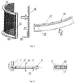
Fig. 2 shows a overall view of the filtering element and its parts. -
Fig. 3 shows the arrangement of an active strainer cleaner pipe. -
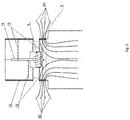
Fig. 4 schematically shows the interaction of the jets from the nozzle of the cleaner and the surface of the filtering element. -
Fig. 5 shows the active strainer of the pit tank of NPP under normal operation, i.e. in the absence of impurities in the fluid. -
Fig. 6 shows the active strainer of the pit tank of NPP when a debris layer is formed on the lower filtering elements in emergency mode, which causes fluid to flow through the upper filtering element. -
Fig. 7 shows the active strainer of the pit tank of NPP in the cleaning mode from impurities and debris. - The active strainer of the NPP pit tank according to preferable embodiment includes a housing with a cover 15, a
lower flange 1 and vertical supports 2 to which alower filtering element 3 and anupper filtering element 14 are attached, located respectively in the lower and upper parts of the housing.Flange 1 is designed to install and connect the active strainer to the base of the pit tank. Vertical support 2 are connected toflange 1. Thelower filtering elements 3 and theupper filtering elements 14 are installed between supports 2, made in the shape of a sector slotted grid connected to theframe 16 of the filtering element and composed ofhorizontal wires 17 andvertical wires 18 made of triangular wire elements. The cylindrical surface of the active strainer is formed of four sectors of thefiltering elements - The
turbine chamber 4 is installed between the upper and lower parts of the active strainer so that the entire flow of fluid entering the upper part of the active strainer passes through it. Theturbine chamber 4 consists of a chamber casing, shaft struts 5, shaft 6, bearing 7, turbine sleeve 8 andturbine blades 9. In theturbine chamber 4, the translational fluid flow is converted into the rotational movement of the sleeve 8 and theturbine blades 9. - The shaft of the
lower cleaner 10 and the shaft of theupper cleaner 11 are connected to the turbine sleeve 8. Pipes ofcleaners 12 are attached to the shafts of the cleaners.Pipes 12 of the cleaner is made in the shape of a profile pipe. Anozzle 13 is installed at the end of the pipe, remote from the central axis of the active strainer, which ensures the distribution of the output jets within the service area of the cleaner. On the opposite side of the cleaner pipe, anopening 19 made in the shape of a through cut-out for fluid intake, when the cleaner rotates in direction 21 (Fig. 3 ) providing thefluid flow 20 into the pipe of thecleaner 12 and then to theholes 22 of thenozzle 13, which can be configured to spray the purified fluid in a wide range of angles in the direction of thefiltering elements Fig. 4 ). - Thus, the design of the active strainer provides for self-cleaning of the surfaces with a reverse flow of purified fluid leaving the
nozzles 13. At the same time, a fluid flow through an active strainer is used as an energy source to create a reverse flow, which increases the safety of NPP operation in emergency conditions, since it does not require the use of external energy sources, for example, pumps, whose operation in emergency conditions is not guaranteed. In addition, the power consumption from the fluid flow for the operation of the turbine and the cleaning of thefiltering elements lower filtering elements 3 are clogged, which reduces the total energy loss of the fluid flow through the active strainer and thereby increases the safety of NPP in emergency conditions. - In a preferred embodiment, the active strainer can be installed at the bottom of the pit tank and tight attached by a
flange 1 to the base mounted above a vertical water intake channel that drains the fluid from the pit tank into the reactor core, so that debris and impurities are discarded from active strainer during its cleaning, settled on the bottom of the pit tank and subsequently did not settle on thefiltering elements - During normal operation of NPP, no coolant leaks occur in it, therefore, there is no fluid flow through the active strainer.
- In the event of an accident that caused the loss of liquid coolant in the core of NPP, this coolant begins to accumulate in the pit tank and upon reaching the level of the
lower filtering elements 3 of the active strainer, flows through them in the water intake system and, subsequently, with the help of pumps, returns to the core. At the same time, thelower filtering elements 3 are not initially clogged with extraneous impurities and debris; therefore, almost the entire fluid flow passes through thelower filtering elements 3, bypassing theturbine blades 9, as a result of which there is no flow through the turbine (Fig. 5 ). In this case, the cleaners do not rotate and the surface of the filtering elements (3, 14) is not cleaned, which eliminates the energy consumption from the fluid flow for rotation of theturbine 9. - Subsequently, upon a fluid with extraneous impurities and debris inflow, the
lower filtering elements 3 become clogged with a debris layer, as shown inFig. 6 , from bottom to top. This process is determined by the distribution of fluid flow over the surface of thefiltering elements 3, in which approximately 80% of the total volume of fluid flows through the lower 20% of the area of thelower filtering elements 3. This process continues until the surface of thelower filtering elements 3 is completely covered with a debris layer. - During this process, the pressure losses on the
lower filtering elements 3 remain almost constant and are determined by the losses on the strainer surfaces of thelower filtering elements 3. The resulting debris layer has a small thickness and a loose structure. - When the
lower filtering elements 3 are completely covered with a debris layer, the main fluid flow begins to flow through theupper filtering elements 14 and, accordingly, through theturbine chamber 4. The turbine begins to rotate and rotates thepipe 12 of the cleaners, which leads to the flow of fluid into the hole for the fluid intake 19 (Fig. 3 ). Further, the incoming fluid accelerates under the action of centrifugal force and with excessive pressure is thrown into thenozzle orifice 13. The distance from thenozzle 13 to the surface of thefiltering element nozzle 13 clean the entire space between adjacent cleaners (Fig. 4 ). - Thus, a local flow is created, directed outward of the active strainer through its
filtering elements filtering elements upper filtering elements 14 is shown inFig. 7 . - During the time the debris is on the
filtering elements - After cleaning the
lower filtering elements 3, the fluid enters the lower part of the active strainer, as a result of which the turbine speed drops. - Further, the filtering-cleaning cycle is periodically repeated. The location of the turbine between the upper and lower parts of the active strainer allows for cleaning periodically after clogging of the
lower filtering device 3. As a result, losses for the rotation of the turbine are reduced in a situation where the cleaning of thefiltering devices - In a preferred embodiment, a graphite plain bearing can be used as a shaft support 6. Graphite bearings have the following advantages: they work in a liquid medium; have a low coefficient of friction; resistant to aggressive environments; used at temperatures up to 500 ° C. Moreover, since the design of the active strainer provides for the rotation of the shaft 6 only in the presence of debris in the solution, i.e. only at the accident. Thus, the service life of the bearing is limited to a period of maximum 30 days.
- A full scan of the filtering surfaces with
nozzles 13 is carried out per one revolution of thecleaner shaft filtering elements - The active pit tank strainer of a nuclear power plant allows to increase its safety under emergency conditions and can be applied for various types of nuclear power plants.
Claims (6)
- The active pit tank strainer of a nuclear power plant comprising a housing with a cover, a base and side surfaces made in the form of filtering elements, pipes with channels fixed at one end at the central vertical axis of the strainer and configured to supply purified fluid from the central part of the strainer to the filtering elements from the other end of the pipe through channels, wherein the strainer housing is made of two parts, an upper and a lower one, each part is equipped with at least one filtering element, the turbine is installed between the upper and lower part and configured to rotate during the fluid flow passage through it, the turbine shaft is connected with the pipes, which are capable of sampling the purified fluid from the strainer housing during rotation of the turbine.
- The active strainer according to claim 1, wherein the side surfaces are cylindrical.
- The active strainer according to claim 1 wherein the ends of the pipes supplying the purified fluid to the filtering elements are equipped with nozzles configured to supply the purified fluid in a wide range of angles.
- The active strainer according to claim 1 wherein the filtering elements are made in the shape of a frame and a sector slotted grid located in it, composed of horizontal and vertical wires of a triangular section.
- The active strainer according to claim 1, wherein the pipes are provided with holes for fluid intake during rotation of the turbine.
- The active strainer according to claim 1, wherein the base is made in the shape of a flange with the possibility of attachment to the base of the pit tank.
Applications Claiming Priority (1)
| Application Number | Priority Date | Filing Date | Title |
|---|---|---|---|
| PCT/RU2017/001007 WO2019132702A1 (en) | 2017-12-29 | 2017-12-29 | Active filter of a nuclear power station sump tank |
Publications (3)
| Publication Number | Publication Date |
|---|---|
| EP3733257A1 true EP3733257A1 (en) | 2020-11-04 |
| EP3733257A4 EP3733257A4 (en) | 2021-08-18 |
| EP3733257B1 EP3733257B1 (en) | 2026-02-04 |
Family
ID=66578948
Family Applications (1)
| Application Number | Title | Priority Date | Filing Date |
|---|---|---|---|
| EP17936660.4A Active EP3733257B1 (en) | 2017-12-29 | 2017-12-29 | Active filter of a nuclear power station sump tank |
Country Status (13)
| Country | Link |
|---|---|
| US (1) | US20210151211A1 (en) |
| EP (1) | EP3733257B1 (en) |
| JP (1) | JP6996037B2 (en) |
| KR (1) | KR102419868B1 (en) |
| CN (1) | CN111032181B (en) |
| CA (1) | CA3068570C (en) |
| EA (1) | EA038937B1 (en) |
| JO (1) | JOP20190296B1 (en) |
| MY (1) | MY200420A (en) |
| RU (1) | RU2687434C1 (en) |
| UA (1) | UA124560C2 (en) |
| WO (1) | WO2019132702A1 (en) |
| ZA (1) | ZA202000718B (en) |
Cited By (1)
| Publication number | Priority date | Publication date | Assignee | Title |
|---|---|---|---|---|
| CN112892034A (en) * | 2021-01-18 | 2021-06-04 | 马志卓 | Multistage filter with cleaning system |
Families Citing this family (5)
| Publication number | Priority date | Publication date | Assignee | Title |
|---|---|---|---|---|
| SE543689C2 (en) * | 2019-10-04 | 2021-06-08 | Mimbly Ab | Improved filter assembly with self-cleaning |
| EP4188576A1 (en) * | 2020-08-03 | 2023-06-07 | Netafim Ltd. | Filter arrangements |
| RU2761441C1 (en) * | 2020-12-30 | 2021-12-08 | Акционерное Общество "Атомэнергопроект" | Coolant flow filtration system of the sump tank of the emergency core cooling system |
| RU2778712C1 (en) * | 2021-12-29 | 2022-08-23 | Акционерное Общество "Атомэнергопроект" | Tank for garbage filtration and collection |
| CN117563320B (en) * | 2024-01-17 | 2024-03-26 | 山西兴新安全生产技术服务有限公司 | Oil-water impurity separation treatment equipment |
Family Cites Families (27)
| Publication number | Priority date | Publication date | Assignee | Title |
|---|---|---|---|---|
| NL7111032A (en) * | 1971-08-11 | 1973-02-13 | Filter - for removal of foreign matter from river or seawater - before industrial use | |
| FR2521446B1 (en) * | 1982-02-15 | 1987-06-05 | Beaudrey & Cie | FIXED STRAINER FILTER IN PARTICULAR FOR INDUSTRIAL WATERS |
| SU1424178A1 (en) * | 1985-07-10 | 1990-09-15 | Всесоюзный Теплотехнический Научно-Исследовательский Институт Им.Ф.Э.Дзержинского | Filter |
| DE3808343A1 (en) * | 1988-03-12 | 1989-09-21 | Kernforschungsz Karlsruhe | Filter insert for a tank filter housing |
| CN2068858U (en) * | 1989-12-06 | 1991-01-09 | 杭州塑料厂 | Self-cleaning spiral-flow filter |
| CN2080562U (en) * | 1990-01-15 | 1991-07-10 | 吴伯南 | Turbine oil purification device |
| US5108592A (en) * | 1990-04-09 | 1992-04-28 | Perfection Sprinkler Co. | Rotary self-cleaning strainer simultaneously cleaned and rotated by nozzle structure |
| JPH04297898A (en) * | 1991-03-27 | 1992-10-21 | Toshiba Corp | Recovering device for control element for high-temperature gas-cooled reactor |
| US5688402A (en) | 1995-12-15 | 1997-11-18 | General Electric Company | Self-cleaning strainer |
| US5815544A (en) | 1997-02-20 | 1998-09-29 | Lefter; Jan D. | Self-cleaning strainer |
| US5835549A (en) * | 1997-03-06 | 1998-11-10 | Combustion Engineering, Inc. | BWR emergency core cooling system strainer |
| GB0306022D0 (en) * | 2003-03-17 | 2003-04-23 | Hosford James P | Filter assembly |
| WO2004105047A2 (en) | 2003-05-15 | 2004-12-02 | Continuum Dynamics, Inc. | Improved self-cleaning strainer |
| KR100519680B1 (en) * | 2003-07-04 | 2005-10-11 | 지철권 | Water treatment apparatus having a back-wash type filter bath |
| US9672947B2 (en) * | 2004-11-15 | 2017-06-06 | Atomic Energy Of Canada Limited | Finned strainer |
| US20070084782A1 (en) * | 2005-10-05 | 2007-04-19 | Enercon Services, Inc. | Filter medium for strainers used in nuclear reactor emergency core cooling systems |
| RU59999U1 (en) * | 2006-08-25 | 2007-01-10 | Андрей Владимирович Перков | SELF-CLEANING FILTER |
| SG174635A1 (en) * | 2010-03-08 | 2011-10-28 | Aalborg Ind Water Treat Pte Ltd | Self-cleaning filter module |
| CN101979121B (en) * | 2010-09-16 | 2012-10-10 | 清华大学 | Self-rotating clean collecting device |
| SG190715A1 (en) * | 2010-12-02 | 2013-07-31 | Amiad Water Systems Ltd | Self cleaning filter system |
| CN103687656B (en) * | 2011-06-01 | 2016-03-02 | 特兰斯科产品股份有限公司 | Large-capacity suction filters for emergency core cooling systems in nuclear power plants |
| KR101517985B1 (en) * | 2012-11-06 | 2015-05-06 | 주식회사 시그너스파워 | a strainer |
| CN105960286B (en) * | 2013-12-05 | 2019-01-29 | 陶氏环球技术有限责任公司 | Hydrocyclone with improved cleaning assembly |
| JP5597314B1 (en) * | 2014-03-12 | 2014-10-01 | ヤマテック株式会社 | Processing equipment |
| KR101580978B1 (en) * | 2014-03-21 | 2015-12-31 | 삼성중공업 주식회사 | Shale shakers for mud treatment |
| CN105056612A (en) * | 2015-09-01 | 2015-11-18 | 江苏神通阀门股份有限公司 | Pit filter |
| CN205886373U (en) * | 2016-07-29 | 2017-01-18 | 南昌绿捷日化有限公司 | From cleaning tube way filter |
-
2017
- 2017-12-29 WO PCT/RU2017/001007 patent/WO2019132702A1/en not_active Ceased
- 2017-12-29 UA UAA201912067A patent/UA124560C2/en unknown
- 2017-12-29 RU RU2018124838A patent/RU2687434C1/en active
- 2017-12-29 CA CA3068570A patent/CA3068570C/en active Active
- 2017-12-29 EA EA201992606A patent/EA038937B1/en unknown
- 2017-12-29 MY MYPI2019007589A patent/MY200420A/en unknown
- 2017-12-29 KR KR1020197038631A patent/KR102419868B1/en active Active
- 2017-12-29 US US16/627,735 patent/US20210151211A1/en not_active Abandoned
- 2017-12-29 CN CN201780092623.8A patent/CN111032181B/en active Active
- 2017-12-29 EP EP17936660.4A patent/EP3733257B1/en active Active
- 2017-12-29 JP JP2019572431A patent/JP6996037B2/en active Active
- 2017-12-29 JO JOJO/P/2019/0296A patent/JOP20190296B1/en active
-
2020
- 2020-02-04 ZA ZA2020/00718A patent/ZA202000718B/en unknown
Cited By (1)
| Publication number | Priority date | Publication date | Assignee | Title |
|---|---|---|---|---|
| CN112892034A (en) * | 2021-01-18 | 2021-06-04 | 马志卓 | Multistage filter with cleaning system |
Also Published As
| Publication number | Publication date |
|---|---|
| KR102419868B1 (en) | 2022-07-12 |
| CN111032181A (en) | 2020-04-17 |
| WO2019132702A1 (en) | 2019-07-04 |
| EA038937B1 (en) | 2021-11-11 |
| ZA202000718B (en) | 2021-04-28 |
| BR112019028195A2 (en) | 2020-07-07 |
| JP6996037B2 (en) | 2022-01-17 |
| JOP20190296B1 (en) | 2024-12-22 |
| JOP20190296A1 (en) | 2019-12-30 |
| KR20200102916A (en) | 2020-09-01 |
| UA124560C2 (en) | 2021-10-05 |
| MY200420A (en) | 2023-12-25 |
| CN111032181B (en) | 2021-12-03 |
| US20210151211A1 (en) | 2021-05-20 |
| CA3068570A1 (en) | 2019-07-04 |
| RU2687434C1 (en) | 2019-05-13 |
| EA201992606A1 (en) | 2020-12-01 |
| JP2020531798A (en) | 2020-11-05 |
| EP3733257B1 (en) | 2026-02-04 |
| CA3068570C (en) | 2022-05-31 |
| EP3733257A4 (en) | 2021-08-18 |
Similar Documents
| Publication | Publication Date | Title |
|---|---|---|
| CA3068570C (en) | Active pit tank strainer of a nuclear power plant | |
| US5688402A (en) | Self-cleaning strainer | |
| CN102407045B (en) | Filter | |
| US20070084782A1 (en) | Filter medium for strainers used in nuclear reactor emergency core cooling systems | |
| KR101025706B1 (en) | Strainer filter including filter tube | |
| KR20220056157A (en) | Self-cleaning liquid cleaning system | |
| EP4458445A1 (en) | Tank for filtering and collecting debris | |
| BR112019028195B1 (en) | ACTIVE FILTER OF A NUCLEAR PLANT TANK | |
| CN216896388U (en) | Pipeline formula simply filters dross removal mechanism | |
| CN108204380B (en) | Immersible pump | |
| CN217220500U (en) | Filter | |
| JP2010230681A (en) | Fluid suction device and emergency core cooling device | |
| JP2010175567A (en) | Fluid suction device and emergency core cooling system | |
| CN219781304U (en) | shellfish trap | |
| CN218504000U (en) | Closed digit control machine tool | |
| CN212974364U (en) | Full-automatic back-flushing water filter | |
| CN220170054U (en) | Silicon carbide heat exchanger convenient to clean | |
| CN222342202U (en) | Filter suitable for concentrated formaldehyde entrained formic acid solution medium | |
| CN213192806U (en) | Antiscaling and descaling water treater | |
| CN220396032U (en) | Prevent self priming pump that impurity blockked up | |
| CN216630006U (en) | Cyclone vertical filtering dirt separator | |
| JP2007218625A (en) | Fluid suction device and emergency core cooling device | |
| CN116905638A (en) | Special anti-blocking floor drain device for nuclear power station | |
| CN203620349U (en) | Self-cleaning filter | |
| CN116518495A (en) | Radiating tube easy to disassemble and connect |
Legal Events
| Date | Code | Title | Description |
|---|---|---|---|
| STAA | Information on the status of an ep patent application or granted ep patent |
Free format text: STATUS: THE INTERNATIONAL PUBLICATION HAS BEEN MADE |
|
| PUAI | Public reference made under article 153(3) epc to a published international application that has entered the european phase |
Free format text: ORIGINAL CODE: 0009012 |
|
| STAA | Information on the status of an ep patent application or granted ep patent |
Free format text: STATUS: REQUEST FOR EXAMINATION WAS MADE |
|
| 17P | Request for examination filed |
Effective date: 20191216 |
|
| AK | Designated contracting states |
Kind code of ref document: A1 Designated state(s): AL AT BE BG CH CY CZ DE DK EE ES FI FR GB GR HR HU IE IS IT LI LT LU LV MC MK MT NL NO PL PT RO RS SE SI SK SM TR |
|
| AX | Request for extension of the european patent |
Extension state: BA ME |
|
| DAV | Request for validation of the european patent (deleted) | ||
| DAX | Request for extension of the european patent (deleted) | ||
| A4 | Supplementary search report drawn up and despatched |
Effective date: 20210715 |
|
| RIC1 | Information provided on ipc code assigned before grant |
Ipc: B01D 29/11 20060101AFI20210709BHEP Ipc: B01D 29/62 20060101ALI20210709BHEP Ipc: G21C 19/307 20060101ALI20210709BHEP Ipc: B01D 29/33 20060101ALI20210709BHEP Ipc: B01D 29/48 20060101ALI20210709BHEP Ipc: B01D 29/54 20060101ALI20210709BHEP Ipc: B01D 29/68 20060101ALI20210709BHEP |
|
| RAP1 | Party data changed (applicant data changed or rights of an application transferred) |
Owner name: JOINT STOCK COMPANY "SCIENCE AND INNOVATIONS" Owner name: JOINT-STOCK COMPANY SCIENTIFIC RESEARCH AND DESIGN INSTITUTE FOR ENERGY TECHNOLOGIES ATOMPROEKT |
|
| STAA | Information on the status of an ep patent application or granted ep patent |
Free format text: STATUS: EXAMINATION IS IN PROGRESS |
|
| 17Q | First examination report despatched |
Effective date: 20230111 |
|
| GRAP | Despatch of communication of intention to grant a patent |
Free format text: ORIGINAL CODE: EPIDOSNIGR1 |
|
| STAA | Information on the status of an ep patent application or granted ep patent |
Free format text: STATUS: GRANT OF PATENT IS INTENDED |
|
| INTG | Intention to grant announced |
Effective date: 20241106 |
|
| GRAJ | Information related to disapproval of communication of intention to grant by the applicant or resumption of examination proceedings by the epo deleted |
Free format text: ORIGINAL CODE: EPIDOSDIGR1 |
|
| STAA | Information on the status of an ep patent application or granted ep patent |
Free format text: STATUS: EXAMINATION IS IN PROGRESS |
|
| GRAP | Despatch of communication of intention to grant a patent |
Free format text: ORIGINAL CODE: EPIDOSNIGR1 |
|
| STAA | Information on the status of an ep patent application or granted ep patent |
Free format text: STATUS: GRANT OF PATENT IS INTENDED |
|
| INTC | Intention to grant announced (deleted) | ||
| INTG | Intention to grant announced |
Effective date: 20250319 |
|
| GRAJ | Information related to disapproval of communication of intention to grant by the applicant or resumption of examination proceedings by the epo deleted |
Free format text: ORIGINAL CODE: EPIDOSDIGR1 |
|
| GRAJ | Information related to disapproval of communication of intention to grant by the applicant or resumption of examination proceedings by the epo deleted |
Free format text: ORIGINAL CODE: EPIDOSDIGR1 |
|
| STAA | Information on the status of an ep patent application or granted ep patent |
Free format text: STATUS: EXAMINATION IS IN PROGRESS |
|
| GRAP | Despatch of communication of intention to grant a patent |
Free format text: ORIGINAL CODE: EPIDOSNIGR1 |
|
| STAA | Information on the status of an ep patent application or granted ep patent |
Free format text: STATUS: GRANT OF PATENT IS INTENDED |
|
| INTG | Intention to grant announced |
Effective date: 20250319 |
|
| INTC | Intention to grant announced (deleted) | ||
| INTG | Intention to grant announced |
Effective date: 20250812 |
|
| GRAS | Grant fee paid |
Free format text: ORIGINAL CODE: EPIDOSNIGR3 |
|
| GRAA | (expected) grant |
Free format text: ORIGINAL CODE: 0009210 |
|
| STAA | Information on the status of an ep patent application or granted ep patent |
Free format text: STATUS: THE PATENT HAS BEEN GRANTED |
|
| AK | Designated contracting states |
Kind code of ref document: B1 Designated state(s): AL AT BE BG CH CY CZ DE DK EE ES FI FR GB GR HR HU IE IS IT LI LT LU LV MC MK MT NL NO PL PT RO RS SE SI SK SM TR |
|
| REG | Reference to a national code |
Ref country code: CH Ref legal event code: F10 Free format text: ST27 STATUS EVENT CODE: U-0-0-F10-F00 (AS PROVIDED BY THE NATIONAL OFFICE) Effective date: 20260204 Ref country code: GB Ref legal event code: FG4D |
|
| REG | Reference to a national code |
Ref country code: IE Ref legal event code: FG4D |
|
| REG | Reference to a national code |
Ref country code: DE Ref legal event code: R096 Ref document number: 602017093807 Country of ref document: DE |