EP3733255B1 - Condensation system for recuperating energy discharge of nuclear power plant - Google Patents
Condensation system for recuperating energy discharge of nuclear power plant Download PDFInfo
- Publication number
- EP3733255B1 EP3733255B1 EP17936024.3A EP17936024A EP3733255B1 EP 3733255 B1 EP3733255 B1 EP 3733255B1 EP 17936024 A EP17936024 A EP 17936024A EP 3733255 B1 EP3733255 B1 EP 3733255B1
- Authority
- EP
- European Patent Office
- Prior art keywords
- outlet
- inlet
- waste water
- water
- condenser
- Prior art date
- Legal status (The legal status is an assumption and is not a legal conclusion. Google has not performed a legal analysis and makes no representation as to the accuracy of the status listed.)
- Active
Links
- 238000009833 condensation Methods 0.000 title description 6
- 230000005494 condensation Effects 0.000 title description 6
- XLYOFNOQVPJJNP-UHFFFAOYSA-N water Substances O XLYOFNOQVPJJNP-UHFFFAOYSA-N 0.000 claims description 76
- 239000002351 wastewater Substances 0.000 claims description 55
- 230000005587 bubbling Effects 0.000 claims description 28
- 239000000498 cooling water Substances 0.000 claims description 13
- 239000013505 freshwater Substances 0.000 description 18
- 238000000034 method Methods 0.000 description 15
- 230000000694 effects Effects 0.000 description 9
- 238000001816 cooling Methods 0.000 description 8
- 238000010438 heat treatment Methods 0.000 description 6
- 238000007599 discharging Methods 0.000 description 5
- 230000008020 evaporation Effects 0.000 description 5
- 238000001704 evaporation Methods 0.000 description 5
- 239000013535 sea water Substances 0.000 description 5
- 230000008014 freezing Effects 0.000 description 4
- 238000007710 freezing Methods 0.000 description 4
- 238000004519 manufacturing process Methods 0.000 description 4
- 239000012535 impurity Substances 0.000 description 3
- 239000000243 solution Substances 0.000 description 3
- 230000002262 irrigation Effects 0.000 description 2
- 238000003973 irrigation Methods 0.000 description 2
- VNWKTOKETHGBQD-UHFFFAOYSA-N methane Chemical compound C VNWKTOKETHGBQD-UHFFFAOYSA-N 0.000 description 2
- 239000008239 natural water Substances 0.000 description 2
- 238000000746 purification Methods 0.000 description 2
- 150000003839 salts Chemical class 0.000 description 2
- 229920006395 saturated elastomer Polymers 0.000 description 2
- 238000000926 separation method Methods 0.000 description 2
- AYEKOFBPNLCAJY-UHFFFAOYSA-O thiamine pyrophosphate Chemical compound CC1=C(CCOP(O)(=O)OP(O)(O)=O)SC=[N+]1CC1=CN=C(C)N=C1N AYEKOFBPNLCAJY-UHFFFAOYSA-O 0.000 description 2
- 239000003643 water by type Substances 0.000 description 2
- 241000196324 Embryophyta Species 0.000 description 1
- 235000015076 Shorea robusta Nutrition 0.000 description 1
- 244000166071 Shorea robusta Species 0.000 description 1
- 239000007795 chemical reaction product Substances 0.000 description 1
- 239000003245 coal Substances 0.000 description 1
- 238000002485 combustion reaction Methods 0.000 description 1
- 230000006835 compression Effects 0.000 description 1
- 238000007906 compression Methods 0.000 description 1
- 230000003750 conditioning effect Effects 0.000 description 1
- 238000011109 contamination Methods 0.000 description 1
- 239000013078 crystal Substances 0.000 description 1
- 230000001419 dependent effect Effects 0.000 description 1
- 230000008021 deposition Effects 0.000 description 1
- 230000001627 detrimental effect Effects 0.000 description 1
- 238000010586 diagram Methods 0.000 description 1
- 239000000446 fuel Substances 0.000 description 1
- 239000000295 fuel oil Substances 0.000 description 1
- 230000008018 melting Effects 0.000 description 1
- 238000002844 melting Methods 0.000 description 1
- 239000000203 mixture Substances 0.000 description 1
- 239000003345 natural gas Substances 0.000 description 1
- 239000002245 particle Substances 0.000 description 1
- 239000003415 peat Substances 0.000 description 1
- 238000001556 precipitation Methods 0.000 description 1
- 239000000047 product Substances 0.000 description 1
- 238000005086 pumping Methods 0.000 description 1
- 230000005855 radiation Effects 0.000 description 1
- 239000012266 salt solution Substances 0.000 description 1
- 239000004576 sand Substances 0.000 description 1
- 230000001932 seasonal effect Effects 0.000 description 1
- 239000007787 solid Substances 0.000 description 1
- 238000000638 solvent extraction Methods 0.000 description 1
- 239000007921 spray Substances 0.000 description 1
- 238000010257 thawing Methods 0.000 description 1
- 238000011144 upstream manufacturing Methods 0.000 description 1
- 239000002918 waste heat Substances 0.000 description 1
- 239000002699 waste material Substances 0.000 description 1
Images

Classifications
-
- B—PERFORMING OPERATIONS; TRANSPORTING
- B01—PHYSICAL OR CHEMICAL PROCESSES OR APPARATUS IN GENERAL
- B01D—SEPARATION
- B01D5/00—Condensation of vapours; Recovering volatile solvents by condensation
- B01D5/0033—Other features
- B01D5/0036—Multiple-effect condensation; Fractional condensation
-
- G—PHYSICS
- G21—NUCLEAR PHYSICS; NUCLEAR ENGINEERING
- G21D—NUCLEAR POWER PLANT
- G21D1/00—Details of nuclear power plant
- G21D1/02—Arrangements of auxiliary equipment
-
- B—PERFORMING OPERATIONS; TRANSPORTING
- B01—PHYSICAL OR CHEMICAL PROCESSES OR APPARATUS IN GENERAL
- B01D—SEPARATION
- B01D3/00—Distillation or related exchange processes in which liquids are contacted with gaseous media, e.g. stripping
- B01D3/007—Energy recuperation; Heat pumps
-
- B—PERFORMING OPERATIONS; TRANSPORTING
- B01—PHYSICAL OR CHEMICAL PROCESSES OR APPARATUS IN GENERAL
- B01D—SEPARATION
- B01D5/00—Condensation of vapours; Recovering volatile solvents by condensation
-
- B—PERFORMING OPERATIONS; TRANSPORTING
- B01—PHYSICAL OR CHEMICAL PROCESSES OR APPARATUS IN GENERAL
- B01D—SEPARATION
- B01D5/00—Condensation of vapours; Recovering volatile solvents by condensation
- B01D5/0027—Condensation of vapours; Recovering volatile solvents by condensation by direct contact between vapours or gases and the cooling medium
-
- C—CHEMISTRY; METALLURGY
- C02—TREATMENT OF WATER, WASTE WATER, SEWAGE, OR SLUDGE
- C02F—TREATMENT OF WATER, WASTE WATER, SEWAGE, OR SLUDGE
- C02F1/00—Treatment of water, waste water, or sewage
- C02F1/02—Treatment of water, waste water, or sewage by heating
- C02F1/04—Treatment of water, waste water, or sewage by heating by distillation or evaporation
- C02F1/041—Treatment of water, waste water, or sewage by heating by distillation or evaporation by means of vapour compression
-
- C—CHEMISTRY; METALLURGY
- C02—TREATMENT OF WATER, WASTE WATER, SEWAGE, OR SLUDGE
- C02F—TREATMENT OF WATER, WASTE WATER, SEWAGE, OR SLUDGE
- C02F1/00—Treatment of water, waste water, or sewage
- C02F1/02—Treatment of water, waste water, or sewage by heating
- C02F1/04—Treatment of water, waste water, or sewage by heating by distillation or evaporation
- C02F1/048—Purification of waste water by evaporation
-
- E—FIXED CONSTRUCTIONS
- E03—WATER SUPPLY; SEWERAGE
- E03B—INSTALLATIONS OR METHODS FOR OBTAINING, COLLECTING, OR DISTRIBUTING WATER
- E03B3/00—Methods or installations for obtaining or collecting drinking water or tap water
- E03B3/28—Methods or installations for obtaining or collecting drinking water or tap water from humid air
-
- G—PHYSICS
- G21—NUCLEAR PHYSICS; NUCLEAR ENGINEERING
- G21D—NUCLEAR POWER PLANT
- G21D1/00—Details of nuclear power plant
- G21D1/04—Pumping arrangements
-
- C—CHEMISTRY; METALLURGY
- C02—TREATMENT OF WATER, WASTE WATER, SEWAGE, OR SLUDGE
- C02F—TREATMENT OF WATER, WASTE WATER, SEWAGE, OR SLUDGE
- C02F1/00—Treatment of water, waste water, or sewage
- C02F1/02—Treatment of water, waste water, or sewage by heating
- C02F1/04—Treatment of water, waste water, or sewage by heating by distillation or evaporation
- C02F1/10—Treatment of water, waste water, or sewage by heating by distillation or evaporation by direct contact with a particulate solid or with a fluid, as a heat transfer medium
-
- C—CHEMISTRY; METALLURGY
- C02—TREATMENT OF WATER, WASTE WATER, SEWAGE, OR SLUDGE
- C02F—TREATMENT OF WATER, WASTE WATER, SEWAGE, OR SLUDGE
- C02F2303/00—Specific treatment goals
- C02F2303/10—Energy recovery
-
- Y—GENERAL TAGGING OF NEW TECHNOLOGICAL DEVELOPMENTS; GENERAL TAGGING OF CROSS-SECTIONAL TECHNOLOGIES SPANNING OVER SEVERAL SECTIONS OF THE IPC; TECHNICAL SUBJECTS COVERED BY FORMER USPC CROSS-REFERENCE ART COLLECTIONS [XRACs] AND DIGESTS
- Y02—TECHNOLOGIES OR APPLICATIONS FOR MITIGATION OR ADAPTATION AGAINST CLIMATE CHANGE
- Y02E—REDUCTION OF GREENHOUSE GAS [GHG] EMISSIONS, RELATED TO ENERGY GENERATION, TRANSMISSION OR DISTRIBUTION
- Y02E30/00—Energy generation of nuclear origin
-
- Y—GENERAL TAGGING OF NEW TECHNOLOGICAL DEVELOPMENTS; GENERAL TAGGING OF CROSS-SECTIONAL TECHNOLOGIES SPANNING OVER SEVERAL SECTIONS OF THE IPC; TECHNICAL SUBJECTS COVERED BY FORMER USPC CROSS-REFERENCE ART COLLECTIONS [XRACs] AND DIGESTS
- Y02—TECHNOLOGIES OR APPLICATIONS FOR MITIGATION OR ADAPTATION AGAINST CLIMATE CHANGE
- Y02P—CLIMATE CHANGE MITIGATION TECHNOLOGIES IN THE PRODUCTION OR PROCESSING OF GOODS
- Y02P70/00—Climate change mitigation technologies in the production process for final industrial or consumer products
- Y02P70/10—Greenhouse gas [GHG] capture, material saving, heat recovery or other energy efficient measures, e.g. motor control, characterised by manufacturing processes, e.g. for rolling metal or metal working
-
- Y—GENERAL TAGGING OF NEW TECHNOLOGICAL DEVELOPMENTS; GENERAL TAGGING OF CROSS-SECTIONAL TECHNOLOGIES SPANNING OVER SEVERAL SECTIONS OF THE IPC; TECHNICAL SUBJECTS COVERED BY FORMER USPC CROSS-REFERENCE ART COLLECTIONS [XRACs] AND DIGESTS
- Y02—TECHNOLOGIES OR APPLICATIONS FOR MITIGATION OR ADAPTATION AGAINST CLIMATE CHANGE
- Y02W—CLIMATE CHANGE MITIGATION TECHNOLOGIES RELATED TO WASTEWATER TREATMENT OR WASTE MANAGEMENT
- Y02W10/00—Technologies for wastewater treatment
- Y02W10/30—Wastewater or sewage treatment systems using renewable energies
- Y02W10/37—Wastewater or sewage treatment systems using renewable energies using solar energy
Definitions
- the invention relates to nuclear power engineering, in particular to systems for recuperating energy discharge of nuclear power plants using thermal energy and air humidity above the water surface of the discharge channel of the nuclear power plant.
- the utilization of excessive thermal emissions of the NPP can increase the COP of the NPP due to the possibility of obtaining not only electric power but also an additional economic effect.
- the utilization of the heat of the waste water of an NPP and a TPP makes it possible to provide heating to a large number of residential and industrial premises.
- this solution is not applicable.
- In and coast regions where NPPs are frequently located in view of the possibility of using large volumes of sea water as cooling water, it is possible to use the power of the NPP for producing freshwater, for which various technical solutions have been applied.
- a device for a mass production of freshwater by condensation of water vapors from air comprising a heat-insulated refrigerating chamber, a pump-compressor for sucking air from the environment into the refrigerating chamber having a pipe for discharging dehydrated cooled air from the chamber, electric heaters for melting the ice produced by condensing water vapors from air, a reservoir for a collection of formed water with a tap and a pipe for discharging water to the outside, the pump-compressor being connected to a coiled heat exchanger, which in its turn is connected to a nozzle, and the refrigerating chamber is by mean of a pipe connected to a chamber separator, where electric heaters and a pipe with a tap are located for discharging produced water to the outside.
- the device is designed for the production of water from atmospheric moisture by freezing of steam using compressed air, its cooling and adiabatic expansion. The obtained fine ice crystals are
- the disadvantages of such a device are the low quality of the obtained water, since there is no separation of non-freezing droplets and solid impurities (salt solutions, sand, etc.), a low cooling rate of compressed air with the help of external air, and also a low productivity with respect to the end product due to the periodicity of thawing.
- the above-mentioned disadvantages do not make it possible to expect a reduction of the effect of the waste water on the environment in the case of its application in the nuclear industry.
- the closest analogue of the claimed invention is a nuclear power complex ( RU patent No. 2504417, publ. 20.01.2009 ) which predominantly is designed for producing freshwater by condensing water vapor from atmospheric air, including an air supply means, a compressor connected to a heat-exchanging device for cooling compressed air, a turbo expander, means for transporting water and air with an armature, a nuclear power plant, wherein the air supply means is in the form of a tower having a height of at least 200 m with air intake ports arranged over the height of the tower, the heat-exchanging device for cooling the compressed air is a condenser which is connected to a droplet separator, both of which are mounted with the possibility of discharging condensate into a pool of the primary condensate, and the turbo expander is connected to the water chamber equipped with a sprinkler connected to a pool of a secondary condensate and a waste water heat exchanger, which is connected to a nuclear power plant.
- the air supply means is in the
- water vapors from atmospheric air pass through an air supply means and a compressor, then pass a first condensation stage with cooling in a condenser, which makes it possible to obtain a primary condensate corresponding with respect to its ecological qualities to rain water.
- a second condensation stage the compressed air passes through a turbo expander where it performs work due to a sharp adiabatic expansion with a temperature drop, so that the moisture contained therein is frozen/condensed to produce a secondary condensate the quality of which corresponds to the natural melt/rain water.
- the nuclear power complex according to the Russian federation patent N° 2504417 makes it possible to obtain an ecologically pure freshwater condensate from atmospheric seawater moisture in large volumes.
- the disadvantages of the method are (1) an insufficient productivity of the process of the production of freshwater when the nuclear power complex is located far away from the sea shore and a dependence of the productivity of the process of the production of freshwater from the daily and seasonal changes of the temperature of the surrounding air, and also (2) the insufficient coefficient of performance of the heat utilization of the NPP, and (3) the impossibility to reduce the negative effect of the thermal discharge of the waste water of the NPP on the environment.
- the object of the present invention is to provide the design of a condensate system of a discharge channel of a nuclear power plant that provides: (1) a high productivity of the process of producing freshwater under any conditions due to recuperation of the thermal energy of the water of the discharge channel of the NPP by utilizing its moist high-temperature steam, and also (2) an increase of the total coefficient of performance with respect to the heat in the NPP and (3) a reduction of the negative effect of the heat of the waste water on the environment.
- US 2013/07494 A1 discloses a connector system according to the preamble of claim 1.
- the object of the invention is achieved by a condensational recuperation system with the features of claim 1.
- Preferred embodiments of the invention are disclosed in the dependent claims.
- the technical result of the present invention is: (1) ensuring a high productivity of the process of producing freshwater under any conditions due to the recuperation of the thermal energy of the water of the discharge channel of the NPP by utilizing its moist high-temperature steam, and also (2) increasing the general coefficient of the heat utilization of the NPP and (3) reducing the negative effect of the waste water on the environment.
- the waste water discharge channel is provided with bubbling pipes arranged below the surface of the waste water and connected by air ducts with the water chamber.
- waste water channel with an effective area of not less than 2000 m 2 per every 100 m of length.
- the advantages of the present invention are: the provision of a high productivity of the process of producing freshwater under any conditions due to the recuperation of the thermal energy of the water of the discharge channel of the NPP by utilizing its moist high-temperature steam, the increase of the total heat utilization factor of the NPP and the reduction of the negative effect of the waste water on the environment.
- the arrangement of the means for the air supply in the discharge channel of the waste water of the NPP, in which there are bubbling pipes below the water surface, connected by an air duct to the water chamber, as well as the introduction of the air-tight roof of the waste water discharge channel makes it possible to ensure the withdrawal of moist steam from the water of the discharge channel of the NPP and thereby to provide a high productivity of the process of producing freshwater under any conditions, to reduce the temperature of the waste water and the negative effect on the environment and also to make it possible to increase the total heat utilization factor of the NPP.
- Fig. 1 is shown a schematic diagram of a preferred embodiment of a waste heat recuperation system of a NPP including a nuclear power plant 1 to which a discharge channel of waste water 2 is connected, in the waste water channel 2 below the water level are arranged bubbling pipes 3 connected to a water chamber 13 by means of a cold air duct, the air part of the discharge channel is connected by a pressure air duct to a compressor 4, which is connected to a condenser 5 connected to the pump station of the cooling water 6, the droplet separator 8 and the additional condensate pool 7, the droplet separator 8 is connected to the additional condensate pool 7 and a turbo expander 9 connected to the electric generator 10 and the water chamber 13.
- the water chamber 13, containing the sprinkler 14, is connected by an air duct to the nuclear power plant 1, with the bubbling compressor 15 and the pressure pipelines - with the additional condensate pool 7 and the condensate pool 12 which is connected to the pump station of pure water 11, which is also connected to the additional condensate pool 7, wherein all of the connections are made by pressure pipelines.
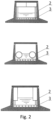
- FIG. 2 shows embodiments of the design of the channel 2 of waste water and the placement of air ducts and bubbling pipes 3 therein.
- the waste water is further cooled by the cold air flowing through the air duct, and when placed above the surface of the water, it is possible to place below the air ducts grooves which are made with the possibility of collecting condensate and transferring it through pipelines outside to the consumer, which improves the productivity of the system.
- the condensate system of the recuperation of the waste energy of NPP preferably is operated as follows.
- the nuclear power plant 1 When the nuclear power plant 1 is operated to condense the steam leaving the turbine of the nuclear power plant, cooling water from an external water reservoir is used.
- the cooling water On passing through the tube bundle of the condenser of the nuclear power plant 1, is heated by 5 to 10°C to a temperature of approximately 35° C, whereupon it is, via the waste water channel 2, in which the bubbling pipes 3 are mounted, discharged back to the sea, river, water reservoir or other external waters.
- air is supplied, which can be taken from the environment, but in the preferred embodiment of the invention through air ducts the cold dehydrated air is supplied from the water chamber 13 by means of the bubbling compressor 15, and because of this it has a lower temperature and humidity (relative humidity about 20%, air temperature of -4°C to +8°C) than the waste water.
- the bubbling pipes 3 may be made in various versions, for example, in the form of perforated pipes.
- the low-temperature waste water is returned via the discharge channel 2 to the sea or other external waters, whereas the moist steam is supplied to the compressor 4 via the pressure air duct, the inlet of which is placed in the air part of the discharge channel 2, and is supplied to the compressor 4, where it is further heated to a temperature above 100°C due to the adiabatic pressure increase, after which it enters the condenser 5 through the pressure air duct.
- heated vapor under pressure is contacted through the walls of heat-exchange pipes/plates with returned water of the thermal net of the NPP and any nearby buildings, or with cold natural water of a nearby water reservoir, or with water taken from the sections of the discharge channel upstream the bubbling pipes 3, by means of the pumping station of sea water 6. Due to the difference in the temperatures of the vapor and the seawater on the heat-exchange pipes/plates of the condenser 5, the temperature of the vapor is reduced to temperatures of 10 to 18°C, i.e.
- This process corresponds to the first, the condensation stage of producing freshwater with purification from its salts and impurities.
- the remaining moist steam under pressure is supplied via the pressure air duct to the droplet separator 8, which may be made, for example, in the form of a slotted-type droplet separator, in which further settling and purification from salt-containing impurities of moisture is carried out, which is then supplied to the additional condensate pool 7 and also represents freshwater corresponding to the quality of rain water.
- the primary condensate obtained in the first stage of producing freshwater can be used for agricultural irrigation, for technical purposes, as well as, in the preferred embodiment of the invention, in the operation of the condensate system of the recuperation of the power emission of the NPP itself, as will be shown below.
- the abrupt adiabatic expansion of the wet vapor in the turbo expander 9 results in the cooling of the vapor to about -10°C and in the freezing of the moisture, remaining in the wet steam up to this moment, which is the second, cryogenic vapor condensing stage. Frozen moisture containing air and particles of snow and ice enters water chamber 13.
- the frozen-out moisture undergoes the process of sprinkling with warm freshwater, which can be fed to the sprinkler 14 via the pressure pipeline from the condenser 5, but in the preferred embodiment of the invention is fed to the sprinkler 14 via the pressure pipeline from the additional condensate pool 7, or from the condensate pool 12, which makes it possible to perform a partial recuperation of the heat of the waste water of the NPP.
- the mixture of air, snow and ice is melted and decomposed into the secondary condensate, which in its quality corresponds to rain water, and in cooled dehydrated air suitable for conditioning of the rooms of the NPP and any nearby buildings, for which purpose pressure ducts connected to the water chamber 13 are used.
- An important preferred feature of the present invention is the connection by means of an air duct of the water chamber 13 with the bubbling pipes 3, which, as shown above, makes it possible due to the high area of evaporation to increase the heat exchange between the pneumatic bubbles with the water of the waste water channel 2 and thereby to ensure the achievement of the technical result of the present invention, i.e.
- the high-purity secondary condensate is fed via a line to the condensate pool 12, whereupon it is possible to use it as technical water, for the irrigation of territories surrounding the NPP, as well as in water supply systems of populated places.
- the sea water pump station can be connected via a pressure line to the channel 2 of the waste water below the bubbling pipes 3, but the compressor - above the bubbling pipes 3. This makes it possible to carry out an additional heat exchange between the condenser 5 and the waste water channel 2, which further reduces the temperature of the waste water.
- condenser 5 and the pump station of the cooling water 6 it is possible to connect the condenser 5 and the pump station of the cooling water 6 to an external heat system, for example an urban heating system.
- an external heat system for example an urban heating system.
- a condensation of steam on condenser 5 will occur with heating of water for the city heating system, which further increases general heat utilization factor of the NPP.
- the channel 2 of the waste water can be divided into sections of 100 m in length by partitioning grids, which do not interfere with the movement of the water but divide the air space of the channel into sections. Moist steam is then taken from each section, and the moisture vapor can be supplied to separate condensate stations, each of which is comprises blocks 4-15 of the present invention.
- Air passing as bubbles through the depth of the water of the discharge channel assumes the temperature of the water (+35°C), while the moisture content of the vapor reaches a value of 32.3 g/kg or 39 g/m 3 (air).
- the productivity (in freshwater) of one condensate system is more than 3 thousand tons/day.
- a temperature drop of the waste water of more than 3°C is reached.
- the condensate system of the recuperation of the power discharge of the nuclear power plant makes it possible to substantially increase the efficiency of the process of producing freshwater by recovering the thermal energy of the waste water of the NPP, to reduce the negative effect of the waste water on the environment and to increase the overall coefficient of utilization of the heat of the NPP.
Landscapes
- Engineering & Computer Science (AREA)
- Physics & Mathematics (AREA)
- Chemical & Material Sciences (AREA)
- Chemical Kinetics & Catalysis (AREA)
- Plasma & Fusion (AREA)
- General Engineering & Computer Science (AREA)
- High Energy & Nuclear Physics (AREA)
- Hydrology & Water Resources (AREA)
- Life Sciences & Earth Sciences (AREA)
- Environmental & Geological Engineering (AREA)
- Water Supply & Treatment (AREA)
- Health & Medical Sciences (AREA)
- Public Health (AREA)
- Organic Chemistry (AREA)
- Heat Treatment Of Water, Waste Water Or Sewage (AREA)
- Physical Water Treatments (AREA)
- Jet Pumps And Other Pumps (AREA)
- Engine Equipment That Uses Special Cycles (AREA)
Description
- The invention relates to nuclear power engineering, in particular to systems for recuperating energy discharge of nuclear power plants using thermal energy and air humidity above the water surface of the discharge channel of the nuclear power plant.
- It is known that under the condition of trouble-free operation of a nuclear power station (NPP) the direct negative impact on the environment is considerably less than that of thermal power plants (TPPs), since for the latter there is an unavoidable emission of combustion products of fuel (coal, natural gas, fuel oil, peat, combustible shales) into the atmosphere. The only factor in which the NPPs are inferior to the ecological balance of the TPP is the thermal contamination caused by the large flow rates of waste water used for cooling of the turbine condensers, which is somewhat higher in the NPP due to the lower coefficient of performance (COP; not more than 35%). In the case where the cooling water is taken from natural water resources (rivers, lakes or seas), which from the economical point of view is economically advantageous for the NPP, this leads to an increase in the temperature of the water resources and is detrimental for the biogeocenosis. In order to combat this factor, modem NPPs are provided with their own artificially designed water reservoirs-coolers, cooling towers or spray basins. However, this does not completely solve the problem because the increased evaporation of these units into the atmosphere changes the ecological environment of the region towards an increase in temperature in conjunction with an increase in humidity, increase of precipitation, appearance of additional cloudiness, etc.
- In addition, the utilization of excessive thermal emissions of the NPP can increase the COP of the NPP due to the possibility of obtaining not only electric power but also an additional economic effect. In cold regions in the winter period the utilization of the heat of the waste water of an NPP and a TPP makes it possible to provide heating to a large number of residential and industrial premises. However, in general, this solution is not applicable. In and coast regions where NPPs are frequently located, in view of the possibility of using large volumes of sea water as cooling water, it is possible to use the power of the NPP for producing freshwater, for which various technical solutions have been applied.
- Known is a device for a mass production of freshwater by condensation of water vapors from air (patent of Russian Federation N° 2143033, publ. 20.12.1999) comprising a heat-insulated refrigerating chamber, a pump-compressor for sucking air from the environment into the refrigerating chamber having a pipe for discharging dehydrated cooled air from the chamber, electric heaters for melting the ice produced by condensing water vapors from air, a reservoir for a collection of formed water with a tap and a pipe for discharging water to the outside, the pump-compressor being connected to a coiled heat exchanger, which in its turn is connected to a nozzle, and the refrigerating chamber is by mean of a pipe connected to a chamber separator, where electric heaters and a pipe with a tap are located for discharging produced water to the outside. The device is designed for the production of water from atmospheric moisture by freezing of steam using compressed air, its cooling and adiabatic expansion. The obtained fine ice crystals are periodically melted by electrical heating with a discharge of water through a tap.
- The disadvantages of such a device are the low quality of the obtained water, since there is no separation of non-freezing droplets and solid impurities (salt solutions, sand, etc.), a low cooling rate of compressed air with the help of external air, and also a low productivity with respect to the end product due to the periodicity of thawing. The above-mentioned disadvantages do not make it possible to expect a reduction of the effect of the waste water on the environment in the case of its application in the nuclear industry.
- The closest analogue of the claimed invention is a nuclear power complex (
RU patent No. 2504417, publ. 20.01.2009 - During operation of the nuclear power complex, water vapors from atmospheric air pass through an air supply means and a compressor, then pass a first condensation stage with cooling in a condenser, which makes it possible to obtain a primary condensate corresponding with respect to its ecological qualities to rain water. Then, in a second condensation stage, the compressed air passes through a turbo expander where it performs work due to a sharp adiabatic expansion with a temperature drop, so that the moisture contained therein is frozen/condensed to produce a secondary condensate the quality of which corresponds to the natural melt/rain water.
- Thus, due to the use of the same processes which in nature lead to the appearance of rain water (low-temperature evaporation under the action of solar radiation and cryogenic freezing of moisture), the nuclear power complex according to the
Russian federation patent N° 2504417 - The object of the present invention is to provide the design of a condensate system of a discharge channel of a nuclear power plant that provides: (1) a high productivity of the process of producing freshwater under any conditions due to recuperation of the thermal energy of the water of the discharge channel of the NPP by utilizing its moist high-temperature steam, and also (2) an increase of the total coefficient of performance with respect to the heat in the NPP and (3) a reduction of the negative effect of the heat of the waste water on the environment.
-
US 2013/07494 A1 discloses a connector system according to the preamble ofclaim 1. The object of the invention is achieved by a condensational recuperation system with the features ofclaim 1. Preferred embodiments of the invention are disclosed in the dependent claims. - The technical result of the present invention is: (1) ensuring a high productivity of the process of producing freshwater under any conditions due to the recuperation of the thermal energy of the water of the discharge channel of the NPP by utilizing its moist high-temperature steam, and also (2) increasing the general coefficient of the heat utilization of the NPP and (3) reducing the negative effect of the waste water on the environment.
- The technical result is achieved by the solution provided in
claim 1. - Preferably, the waste water discharge channel is provided with bubbling pipes arranged below the surface of the waste water and connected by air ducts with the water chamber.
- It is expedient to make the waste water channel with an effective area of not less than 2000 m2 per every 100 m of length.
- It is preferred to provide an air duct connecting the water chamber with the bubbling pipes, a bubbling compressor.
- It is expedient to connect the pump station of cooling water by a pressure pipeline with the discharge channel of waste water below the bubbling pipes, and to connect the compressor by means of a pressure pipeline with the discharge channel of waste water above the bubbling pipes.
- It is recommended to connect the pump station of the cooling water and the condenser to an external heating system (NPP, industrial plant, populated places, etc.).
- It is preferable to connect the sprinkler of the water chamber with a pressure pipeline with the condensate pool.
- It is expedient to arrange parts of the air ducts, which are located in the discharge channel of the waste water, above the surface of the waste water and to provide them with ducts having the possibility of collecting condensate and being connected to the pipelines for discharging condensate outside the channel of the waste water.
- The advantages of the present invention are: the provision of a high productivity of the process of producing freshwater under any conditions due to the recuperation of the thermal energy of the water of the discharge channel of the NPP by utilizing its moist high-temperature steam, the increase of the total heat utilization factor of the NPP and the reduction of the negative effect of the waste water on the environment.
- The arrangement of the means for the air supply in the discharge channel of the waste water of the NPP, in which there are bubbling pipes below the water surface, connected by an air duct to the water chamber, as well as the introduction of the air-tight roof of the waste water discharge channel makes it possible to ensure the withdrawal of moist steam from the water of the discharge channel of the NPP and thereby to provide a high productivity of the process of producing freshwater under any conditions, to reduce the temperature of the waste water and the negative effect on the environment and also to make it possible to increase the total heat utilization factor of the NPP.
- In
Fig. 1 is shown a schematic diagram of a preferred embodiment of a waste heat recuperation system of a NPP including anuclear power plant 1 to which a discharge channel ofwaste water 2 is connected, in thewaste water channel 2 below the water level are arranged bubblingpipes 3 connected to awater chamber 13 by means of a cold air duct, the air part of the discharge channel is connected by a pressure air duct to a compressor 4, which is connected to acondenser 5 connected to the pump station of thecooling water 6, thedroplet separator 8 and theadditional condensate pool 7, thedroplet separator 8 is connected to theadditional condensate pool 7 and a turbo expander 9 connected to theelectric generator 10 and thewater chamber 13. Thewater chamber 13, containing thesprinkler 14, is connected by an air duct to thenuclear power plant 1, with thebubbling compressor 15 and the pressure pipelines - with theadditional condensate pool 7 and thecondensate pool 12 which is connected to the pump station ofpure water 11, which is also connected to theadditional condensate pool 7, wherein all of the connections are made by pressure pipelines. -
FIG. 2 shows embodiments of the design of thechannel 2 of waste water and the placement of air ducts and bubblingpipes 3 therein. When the pipes are partially placed below the surface of the waste water, the waste water is further cooled by the cold air flowing through the air duct, and when placed above the surface of the water, it is possible to place below the air ducts grooves which are made with the possibility of collecting condensate and transferring it through pipelines outside to the consumer, which improves the productivity of the system. - The condensate system of the recuperation of the waste energy of NPP preferably is operated as follows. When the
nuclear power plant 1 is operated to condense the steam leaving the turbine of the nuclear power plant, cooling water from an external water reservoir is used. In the heat exchange process the cooling water, on passing through the tube bundle of the condenser of thenuclear power plant 1, is heated by 5 to 10°C to a temperature of approximately 35° C, whereupon it is, via thewaste water channel 2, in which thebubbling pipes 3 are mounted, discharged back to the sea, river, water reservoir or other external waters. To increase the evaporation area, to the bubblingpipes 3 air is supplied, which can be taken from the environment, but in the preferred embodiment of the invention through air ducts the cold dehydrated air is supplied from thewater chamber 13 by means of thebubbling compressor 15, and because of this it has a lower temperature and humidity (relative humidity about 20%, air temperature of -4°C to +8°C) than the waste water. Due to this air bubbles leaving thebubbling pipes 3 and on passing through the volume of the waste water take the water temperature of the discharge channel and get saturated with moisture (the moisture content of the vapor in the bubbles reaches 32.3 g/kg or 39 g/m3 of air), and after the bubbles escape to the surface of the water in thedischarge channel 2, they form a moist steam (warm air saturated with water vapor). Thebubbling pipes 3 may be made in various versions, for example, in the form of perforated pipes. - After passing along the
bubbling pipes 3, the low-temperature waste water is returned via thedischarge channel 2 to the sea or other external waters, whereas the moist steam is supplied to the compressor 4 via the pressure air duct, the inlet of which is placed in the air part of thedischarge channel 2, and is supplied to the compressor 4, where it is further heated to a temperature above 100°C due to the adiabatic pressure increase, after which it enters thecondenser 5 through the pressure air duct. Incondenser 5, heated vapor under pressure is contacted through the walls of heat-exchange pipes/plates with returned water of the thermal net of the NPP and any nearby buildings, or with cold natural water of a nearby water reservoir, or with water taken from the sections of the discharge channel upstream thebubbling pipes 3, by means of the pumping station ofsea water 6. Due to the difference in the temperatures of the vapor and the seawater on the heat-exchange pipes/plates of thecondenser 5, the temperature of the vapor is reduced to temperatures of 10 to 18°C, i.e. below the dew point of the source air, which results in partial deposition on the surfaces of thecondenser 5 of moisture, which is then discharged into theadditional condensate pool 7 and represents a freshwater corresponding in quality to rain water. This process corresponds to the first, the condensation stage of producing freshwater with purification from its salts and impurities. After that, the remaining moist steam under pressure is supplied via the pressure air duct to thedroplet separator 8, which may be made, for example, in the form of a slotted-type droplet separator, in which further settling and purification from salt-containing impurities of moisture is carried out, which is then supplied to theadditional condensate pool 7 and also represents freshwater corresponding to the quality of rain water. - The primary condensate obtained in the first stage of producing freshwater can be used for agricultural irrigation, for technical purposes, as well as, in the preferred embodiment of the invention, in the operation of the condensate system of the recuperation of the power emission of the NPP itself, as will be shown below.
- The moist steam remaining after the separation of the primary condensate from the
condenser 5 under pressure via the pressure line enters the turbo expander 9 in which it is subjected to an adiabatic expansion with pressure and temperature reduction in the operation of the turbine of the turbo expander 9, whereby the extracted energy is converted into electrical energy by means of anelectric current generator 10, which also provides partial recuperation of the energy supplied to compressor 4 for the primary compression of steam. The abrupt adiabatic expansion of the wet vapor in the turbo expander 9 results in the cooling of the vapor to about -10°C and in the freezing of the moisture, remaining in the wet steam up to this moment, which is the second, cryogenic vapor condensing stage. Frozen moisture containing air and particles of snow and ice enterswater chamber 13. - In the
sprinkler 14 of thewater chamber 13 the frozen-out moisture undergoes the process of sprinkling with warm freshwater, which can be fed to thesprinkler 14 via the pressure pipeline from thecondenser 5, but in the preferred embodiment of the invention is fed to thesprinkler 14 via the pressure pipeline from theadditional condensate pool 7, or from thecondensate pool 12, which makes it possible to perform a partial recuperation of the heat of the waste water of the NPP. As a result of sprinkling, the mixture of air, snow and ice is melted and decomposed into the secondary condensate, which in its quality corresponds to rain water, and in cooled dehydrated air suitable for conditioning of the rooms of the NPP and any nearby buildings, for which purpose pressure ducts connected to thewater chamber 13 are used. An important preferred feature of the present invention is the connection by means of an air duct of thewater chamber 13 with thebubbling pipes 3, which, as shown above, makes it possible due to the high area of evaporation to increase the heat exchange between the pneumatic bubbles with the water of thewaste water channel 2 and thereby to ensure the achievement of the technical result of the present invention, i.e. to ensure a high efficiency of the process of producing freshwater under any conditions due to a recuperation of thermal energy of the discharge channel of the NPP, to reduce the negative effect of the waste water on the environment and to increase the overall coefficient of performance of the heat of the NPP. In this, the high-purity secondary condensate is fed via a line to thecondensate pool 12, whereupon it is possible to use it as technical water, for the irrigation of territories surrounding the NPP, as well as in water supply systems of populated places. - In the case of a utilization of the system for NPP/TPPs having an energy output of less than 1000 MW a utilization of the recuperation system of the energy output without the use of the
drop separator 8 becomes advantageous. In this utilization mode the moist steam downstream of the compressor 4 is fed directly to the turbo expander 9, from which it is sent to thewater chamber 13, where it is condensed in the second stage by the method disclosed above. - For additional moisture and steam temperature is it possible to use passive floating impellers installed in
channel 2 of waste water with a possibility of forming a developed relief of the water surface. In this case, the surface area of the evaporation increases, which increases the humidity and the temperature of the vapor. In this case, in the case of an important (greater than 300 m) length of thechannel 2 of waste water, it is possible to separately apply the bubblingpipes 3 and the floating impellers at various sections of thewaste water channel 2 with a discharge of steam from each section according to the present invention. - In an embodiment of the invention, the sea water pump station can be connected via a pressure line to the
channel 2 of the waste water below the bubblingpipes 3, but the compressor - above the bubblingpipes 3. This makes it possible to carry out an additional heat exchange between thecondenser 5 and thewaste water channel 2, which further reduces the temperature of the waste water. - Furthermore, according to still another embodiment of the invention, it is possible to connect the
condenser 5 and the pump station of the coolingwater 6 to an external heat system, for example an urban heating system. In this case, a condensation of steam oncondenser 5 will occur with heating of water for the city heating system, which further increases general heat utilization factor of the NPP. - Calculations show a high application efficiency of the present invention. At the estimated dimensions (
FIG. 2 ) of thechannel 2 of the waste water: width - 10m, height - 6m, length-800m and depth of the water in the channel - 3m the flow of water in thechannel 2 of the waste water is 66 t/s. The perforated underwater bubbling pipes (100 pipes, each in the section 0.07 m2) are located at the bottom (across the axis) of the discharge channel at a distance of 1 m and more from each other, connecting the main pipes and providing the process of air discharge uniformly in a volume of 400 m3/sec and more. In a preferred embodiment, thechannel 2 of the waste water can be divided into sections of 100 m in length by partitioning grids, which do not interfere with the movement of the water but divide the air space of the channel into sections. Moist steam is then taken from each section, and the moisture vapor can be supplied to separate condensate stations, each of which is comprises blocks 4-15 of the present invention. To the volume of the discharge water of each section of thechannel 2 by bubbling at a rate of 1000 m/s air is charged from the outlet of the condenser station (relative humidity 20%, air temperature from -4°C to +8°C). Air passing as bubbles through the depth of the water of the discharge channel assumes the temperature of the water (+35°C), while the moisture content of the vapor reaches a value of 32.3 g/kg or 39 g/m3 (air). The productivity (in freshwater) of one condensate system is more than 3 thousand tons/day. In the case of a discharge channel with 6 condensate stations of the preferred embodiment of the recuperation of the energy output, a temperature drop of the waste water of more than 3°C is reached. - The condensate system of the recuperation of the power discharge of the nuclear power plant makes it possible to substantially increase the efficiency of the process of producing freshwater by recovering the thermal energy of the waste water of the NPP, to reduce the negative effect of the waste water on the environment and to increase the overall coefficient of utilization of the heat of the NPP.
Claims (8)
- Condensational recuperation system for the energy output of a nuclear power station, comprising a nuclear power plant (1), an air intake means (3), a compressor (4), a condenser (5), a water chamber (13) provided with a sprinkler (14), an electric current generator (10), a pure water pump station (11), a cooling water pump station (6) for cooling water supply to condenser (5), a condensate pool (12), and a turbo expander (9), an outlet of the air intake means (3) being connected to an inlet of the compressor (4) by a pipeline, an outlet of the compressor (4) being connected to an inlet of the condenser (5) by a pipeline, an outlet of the condenser (5) being connected to an inlet of the turbo expander (9) provided with the electric current generator (10) by a pipeline, an outlet of the turbo expander (9) being connected to an inlet of the water chamber (13) by a pipeline, an outlet of the water chamber (13) being connected to an inlet of the condensate pool (12) by a pipeline, an outlet of the condensate pool (12) being connected to a pump station (11) of pure water, the condenser (5) being connected to an outlet of the pump station (6) of cooling water, all of the connections being made in the form of pressure pipelines, wherein the air intake means (3) is arranged in a waste water channel (2) for supplying air by bubbling pipes (3) into the waste water channel (2), characterized in that the waste water channel (2) is the waste water channel (2) of the nuclear power plant (1) connected to an outlet of the nuclear power plant (1), and the waste water channel (2) is provided with a sealed roof, and the condensational recuperation system is further provided with a droplet separator (8) and an additional condensate pool (7), a moist steam outlet of the condenser (5) is connected by a pressure pipeline to the inlet of the droplet separator (8), the outlet of which is connected to the inlet of the turbo expander (9) by a pressure pipeline, and another outlet of said droplet separator (8) is connected to the inlet of the additional condensate pool (7), a moisture outlet of the condenser (5) is connected by a pressure pipeline to the inlet of the additional condensate pool (7), and the outlet of the additional condensate pool (7) is connected to the inlet of the water chamber sprinkler (14) and to the inlet of the pure water pump station (11) by pressure pipelines.
- System according to claim 1, characterized in that the bubbling pipes (3) are arranged below the surface of the waste water and their inlets are connected by means of air ducts to the outlet of the water chamber (13).
- System according to any of the preceding claims, wherein the waste water channel (2) has a total area of not less than 2000 m2 per 100 m of its length.
- System according to claim 2, characterized in that a bubbling compressor (15) is installed in the air duct connecting the outlet of the water chamber with inlets of the bubbling pipes (3).
- System according to claim 2, characterized in that the inlet of the pump station of the cooling water (6) is connected by a pressure pipeline to the outlet of the waste water channel (2) below the bubbling pipes (3), the inlet of the compressor (4) is connected by a pressure pipeline to the outlet of the waste water channel (2) above the bubbling pipes (3).
- System according to any of the preceding claims, wherein outlets of the cooling water pump station (6) and the condenser are connected to an external heat system.
- System according to any of the preceding claims, wherein the inlet of the sprinkler (14) of the water chamber (13) is connected to the outlet of the condensate pool (12) by means of a pressure pipeline.
- System according to claim 2, characterized in that the parts of the air ducts located in the waste water channel (2) are located above the surface of the waste water and are provided with water ducts provided with the possibility of collecting condensate and connected by its outlets to the pipelines for discharge of the condensate outside the waste water channel (2).
Priority Applications (1)
| Application Number | Priority Date | Filing Date | Title |
|---|---|---|---|
| HUE17936024A HUE065913T2 (en) | 2017-12-29 | 2017-12-29 | Condensation system for recuperating energy discharge of nuclear power plant |
Applications Claiming Priority (1)
| Application Number | Priority Date | Filing Date | Title |
|---|---|---|---|
| PCT/RU2017/001008 WO2019132703A1 (en) | 2017-12-29 | 2017-12-29 | Condensation system for recuperating energy discharge of nuclear power plant |
Publications (3)
| Publication Number | Publication Date |
|---|---|
| EP3733255A1 EP3733255A1 (en) | 2020-11-04 |
| EP3733255A4 EP3733255A4 (en) | 2021-04-28 |
| EP3733255B1 true EP3733255B1 (en) | 2023-11-22 |
Family
ID=67067889
Family Applications (1)
| Application Number | Title | Priority Date | Filing Date |
|---|---|---|---|
| EP17936024.3A Active EP3733255B1 (en) | 2017-12-29 | 2017-12-29 | Condensation system for recuperating energy discharge of nuclear power plant |
Country Status (12)
| Country | Link |
|---|---|
| US (1) | US11984234B2 (en) |
| EP (1) | EP3733255B1 (en) |
| JP (1) | JP7188795B2 (en) |
| KR (1) | KR102545027B1 (en) |
| CN (1) | CN112135675A (en) |
| CA (1) | CA3107479C (en) |
| EA (1) | EA202091562A1 (en) |
| FI (1) | FI3733255T3 (en) |
| HU (1) | HUE065913T2 (en) |
| JO (1) | JOP20200163A1 (en) |
| RU (1) | RU2737376C1 (en) |
| WO (1) | WO2019132703A1 (en) |
Families Citing this family (2)
| Publication number | Priority date | Publication date | Assignee | Title |
|---|---|---|---|---|
| CN113035386B (en) * | 2021-03-05 | 2022-11-18 | 哈尔滨工程大学 | Containment built-in efficient heat exchanger adopting double-wheel double-blade composite power air suction type |
| CN114941863A (en) * | 2022-05-12 | 2022-08-26 | 华能(大连)热电有限责任公司 | Heat supply network drainage grading recovery device and recovery method thereof |
Family Cites Families (23)
| Publication number | Priority date | Publication date | Assignee | Title |
|---|---|---|---|---|
| BE567155A (en) * | 1957-04-26 | |||
| DE3319975A1 (en) * | 1983-06-01 | 1984-12-06 | Technica Entwicklungsgesellschaft mbH & Co KG, 2418 Ratzeburg | Apparatus for obtaining drinking water |
| JPS6275299A (en) * | 1985-09-27 | 1987-04-07 | 株式会社東芝 | Condenser exhaust-heat utilizer for nuclear power plant |
| RU2062838C1 (en) * | 1992-05-06 | 1996-06-27 | Виктор Дмитриевич Куликов | Device for taking drinking water from air |
| RU2056479C1 (en) * | 1993-04-12 | 1996-03-20 | Вячеслав Викторович Алексеев | Facility for generation of fresh water from wet air |
| RU2109112C1 (en) * | 1997-03-17 | 1998-04-20 | Игорь Иванович Шрейн | Device for producing basically sweet water |
| RU2143033C1 (en) * | 1998-08-21 | 1999-12-20 | Цивинский Станислав Викторович | Device for mass production of fresh water by condensation of water vapors from air |
| JP2001215294A (en) * | 1999-11-22 | 2001-08-10 | Japan Organo Co Ltd | Condensate demineralizer |
| US6684648B2 (en) * | 2000-07-26 | 2004-02-03 | Fakieh Research & Development Center | Apparatus for the production of freshwater from extremely hot and humid air |
| AU2002368198A1 (en) * | 2002-08-30 | 2004-03-19 | Matthew E. Clasby Jr. | Device for extracting water from the atmosphere |
| WO2005115598A2 (en) * | 2004-05-25 | 2005-12-08 | The Board Of Trustees Of The University Of Arkansas | System and method for dissolving gases in liquids |
| ZA200809457B (en) * | 2006-04-05 | 2010-04-28 | Ben M Enis | Desalination method and system using compressed air energy systems |
| DE102006050922A1 (en) * | 2006-10-28 | 2008-04-30 | Hans Huber Ag Maschinen- Und Anlagenbau | Transmitting heat between wastewater e.g. domestic wastewater located in sand trap and fluid e.g. oil by heat exchanger, comprises producing convective flow that moves the wastewater along outer surface of the exchanger, in the wastewater |
| WO2009000019A1 (en) * | 2007-06-22 | 2008-12-31 | Gomtech Pty Ltd | Selective removal of a target liquid constituent from a multi-component liquid |
| US8647477B2 (en) * | 2011-02-15 | 2014-02-11 | Massachusetts Institute Of Technology | High-efficiency thermal-energy-driven water purification system |
| US9072984B2 (en) * | 2011-09-23 | 2015-07-07 | Massachusetts Institute Of Technology | Bubble-column vapor mixture condenser |
| RU122199U1 (en) * | 2012-06-04 | 2012-11-20 | Открытое акционерное общество "Российский концерн по производству электрической и тепловой энергии на атомных станциях" (ОАО "Концерн Росэнергоатом") | WATER DISCHARGE OF A NUCLEAR POWER PLANT |
| DE102012213489A1 (en) * | 2012-07-31 | 2014-02-06 | Areva Gmbh | Heat removal system for a nuclear installation |
| RU2504417C1 (en) | 2012-09-19 | 2014-01-20 | Открытое акционерное общество "Восточно-Европейский головной научно- исследовательский и проектный институт энергетических технологий" (ОАО "Головной институт "ВНИПИЭТ") | Nuclear power complex |
| WO2014190294A1 (en) * | 2013-05-24 | 2014-11-27 | Sweetwater Energy, Inc. | Sugar separation and purification from biomass |
| US9852819B2 (en) * | 2014-01-22 | 2017-12-26 | Willard Harvey Wattenburg | Passive nuclear reactor cooling system using compressed gas energy and coolant storage outside nuclear plant |
| FR3016876B1 (en) * | 2014-01-24 | 2021-01-01 | Starklab | INSTALLATION AND PROCESS OF TREATMENT BY EVAPORATION / CONDENSATION OF PUMPED WATER IN A NATURAL ENVIRONMENT |
| EP3161217A4 (en) * | 2014-06-30 | 2018-04-04 | Robert Kremer | An apparatus, system and method for utilizing thermal energy |
-
2017
- 2017-12-29 CN CN201780098076.4A patent/CN112135675A/en active Pending
- 2017-12-29 RU RU2019128158A patent/RU2737376C1/en active
- 2017-12-29 JP JP2020536123A patent/JP7188795B2/en active Active
- 2017-12-29 EP EP17936024.3A patent/EP3733255B1/en active Active
- 2017-12-29 WO PCT/RU2017/001008 patent/WO2019132703A1/en active Application Filing
- 2017-12-29 CA CA3107479A patent/CA3107479C/en active Active
- 2017-12-29 KR KR1020207021670A patent/KR102545027B1/en active IP Right Grant
- 2017-12-29 EA EA202091562A patent/EA202091562A1/en unknown
- 2017-12-29 JO JOP/2020/0163A patent/JOP20200163A1/en unknown
- 2017-12-29 FI FIEP17936024.3T patent/FI3733255T3/en active
- 2017-12-29 US US16/959,091 patent/US11984234B2/en active Active
- 2017-12-29 HU HUE17936024A patent/HUE065913T2/en unknown
Also Published As
| Publication number | Publication date |
|---|---|
| RU2737376C1 (en) | 2020-11-27 |
| US11984234B2 (en) | 2024-05-14 |
| JP2021516331A (en) | 2021-07-01 |
| EA202091562A1 (en) | 2021-04-08 |
| CA3107479C (en) | 2023-07-04 |
| KR102545027B1 (en) | 2023-06-20 |
| HUE065913T2 (en) | 2024-06-28 |
| JOP20200163A1 (en) | 2020-06-29 |
| FI3733255T3 (en) | 2024-02-15 |
| BR112020013368A2 (en) | 2020-12-01 |
| EP3733255A4 (en) | 2021-04-28 |
| WO2019132703A1 (en) | 2019-07-04 |
| US20200335235A1 (en) | 2020-10-22 |
| JP7188795B2 (en) | 2022-12-13 |
| CA3107479A1 (en) | 2019-07-04 |
| CN112135675A (en) | 2020-12-25 |
| KR20200102482A (en) | 2020-08-31 |
| EP3733255A1 (en) | 2020-11-04 |
Similar Documents
| Publication | Publication Date | Title |
|---|---|---|
| US6919000B2 (en) | Diffusion driven desalination apparatus and process | |
| US7225620B2 (en) | Diffusion driven water purification apparatus and process | |
| CN201999824U (en) | Sea water desalination system combining solar heat pump and air conditioner | |
| US9903272B2 (en) | Method and apparatus for integrating on-shore green and other on-shore power sources with a compressed air energy storage system on a floating power plant | |
| CN105403067B (en) | One kind utilizes industrial exhaust heat condensed water demisting cooling tower | |
| CN103043735B (en) | Heat pump type small seawater desalting device | |
| EP3733255B1 (en) | Condensation system for recuperating energy discharge of nuclear power plant | |
| CN102381796A (en) | Solar photovoltaic photothermal integrated device for seawater desalination | |
| CN103613155A (en) | Heat pipe type low temperature two-effect sea water desalting device | |
| CN104944492A (en) | Cooperative production method integrating air conditioning and parallel-flow seawater desalination and being usable in summer and winter | |
| WO2011067592A1 (en) | Desalination apparatus, a module for use in a desalination apparatus, and a method of desalinating a saline water source | |
| Zarza et al. | Solar thermal desalination project at the Plataforma Solar de Almeria | |
| RU2504417C1 (en) | Nuclear power complex | |
| CN102267733A (en) | Industrial waste heat low-temperature multi-effect seawater desalting system | |
| CN110145946B (en) | Water-saving switching type natural ventilation cooling tower | |
| CN202116342U (en) | Industrial exhaust heat low-temperature multiple-effect seawater desalinization system | |
| US5829255A (en) | System and method for direct-contact condensation with condensate in steam-turbine power plants evaporators | |
| EA042215B1 (en) | CONDENSATE ENERGY RECOVERY SYSTEM OF NUCLEAR POWER PLANT | |
| CN210486571U (en) | Water-saving switching type natural ventilation cooling tower | |
| CN100467833C (en) | Dual-purpose vacuum apparatus for industrial afterheat power generation and flue gas dust collection | |
| WO2004060812A1 (en) | Diffusion driven desalination apparatus and process | |
| BR112020013368B1 (en) | CONDENSATE SYSTEM FOR RECOVERING ENERGY FROM A NUCLEAR POWER PLANT | |
| Fares et al. | Water Desalination Using a New Humidification-Dehumidification (HDH) Technology | |
| CN108392974B (en) | System for reducing emission of white smoke plume water vapor of thermal power plant | |
| CN104961182A (en) | Transcritical air-conditioner and seawater desalination combined production system used in both winter and summer |
Legal Events
| Date | Code | Title | Description |
|---|---|---|---|
| STAA | Information on the status of an ep patent application or granted ep patent |
Free format text: STATUS: THE INTERNATIONAL PUBLICATION HAS BEEN MADE |
|
| PUAI | Public reference made under article 153(3) epc to a published international application that has entered the european phase |
Free format text: ORIGINAL CODE: 0009012 |
|
| STAA | Information on the status of an ep patent application or granted ep patent |
Free format text: STATUS: REQUEST FOR EXAMINATION WAS MADE |
|
| 17P | Request for examination filed |
Effective date: 20200717 |
|
| AK | Designated contracting states |
Kind code of ref document: A1 Designated state(s): AL AT BE BG CH CY CZ DE DK EE ES FI FR GB GR HR HU IE IS IT LI LT LU LV MC MK MT NL NO PL PT RO RS SE SI SK SM TR |
|
| AX | Request for extension of the european patent |
Extension state: BA ME |
|
| DAV | Request for validation of the european patent (deleted) | ||
| DAX | Request for extension of the european patent (deleted) | ||
| A4 | Supplementary search report drawn up and despatched |
Effective date: 20210326 |
|
| RIC1 | Information provided on ipc code assigned before grant |
Ipc: B01D 5/00 20060101AFI20210322BHEP Ipc: E03B 3/28 20060101ALI20210322BHEP Ipc: G21D 1/02 20060101ALI20210322BHEP Ipc: B01D 3/00 20060101ALI20210322BHEP Ipc: C02F 1/04 20060101ALI20210322BHEP Ipc: C02F 1/10 20060101ALI20210322BHEP |
|
| STAA | Information on the status of an ep patent application or granted ep patent |
Free format text: STATUS: EXAMINATION IS IN PROGRESS |
|
| 17Q | First examination report despatched |
Effective date: 20220104 |
|
| RAP1 | Party data changed (applicant data changed or rights of an application transferred) |
Owner name: JOINT STOCK COMPANY "SCIENCE AND INNOVATIONS" Owner name: JOINT STOCK COMPANY "ATOMENERGOPROEKT" |
|
| GRAP | Despatch of communication of intention to grant a patent |
Free format text: ORIGINAL CODE: EPIDOSNIGR1 |
|
| STAA | Information on the status of an ep patent application or granted ep patent |
Free format text: STATUS: GRANT OF PATENT IS INTENDED |
|
| INTG | Intention to grant announced |
Effective date: 20230630 |
|
| GRAS | Grant fee paid |
Free format text: ORIGINAL CODE: EPIDOSNIGR3 |
|
| GRAA | (expected) grant |
Free format text: ORIGINAL CODE: 0009210 |
|
| STAA | Information on the status of an ep patent application or granted ep patent |
Free format text: STATUS: THE PATENT HAS BEEN GRANTED |
|
| AK | Designated contracting states |
Kind code of ref document: B1 Designated state(s): AL AT BE BG CH CY CZ DE DK EE ES FI FR GB GR HR HU IE IS IT LI LT LU LV MC MK MT NL NO PL PT RO RS SE SI SK SM TR |
|
| REG | Reference to a national code |
Ref country code: GB Ref legal event code: FG4D |
|
| REG | Reference to a national code |
Ref country code: CH Ref legal event code: EP |
|
| REG | Reference to a national code |
Ref country code: DE Ref legal event code: R096 Ref document number: 602017076885 Country of ref document: DE |
|
| REG | Reference to a national code |
Ref country code: IE Ref legal event code: FG4D |
|
| REG | Reference to a national code |
Ref country code: NL Ref legal event code: FP |
|
| PGFP | Annual fee paid to national office [announced via postgrant information from national office to epo] |
Ref country code: NL Payment date: 20240109 Year of fee payment: 7 |
|
| PGFP | Annual fee paid to national office [announced via postgrant information from national office to epo] |
Ref country code: LU Payment date: 20240109 Year of fee payment: 7 |
|
| REG | Reference to a national code |
Ref country code: SE Ref legal event code: TRGR |
|
| REG | Reference to a national code |
Ref country code: LT Ref legal event code: MG9D |
|
| PG25 | Lapsed in a contracting state [announced via postgrant information from national office to epo] |
Ref country code: GR Free format text: LAPSE BECAUSE OF FAILURE TO SUBMIT A TRANSLATION OF THE DESCRIPTION OR TO PAY THE FEE WITHIN THE PRESCRIBED TIME-LIMIT Effective date: 20240223 |
|
| PG25 | Lapsed in a contracting state [announced via postgrant information from national office to epo] |
Ref country code: IS Free format text: LAPSE BECAUSE OF FAILURE TO SUBMIT A TRANSLATION OF THE DESCRIPTION OR TO PAY THE FEE WITHIN THE PRESCRIBED TIME-LIMIT Effective date: 20240322 |
|
| REG | Reference to a national code |
Ref country code: SK Ref legal event code: T3 Ref document number: E 43572 Country of ref document: SK |
|
| PG25 | Lapsed in a contracting state [announced via postgrant information from national office to epo] |
Ref country code: LT Free format text: LAPSE BECAUSE OF FAILURE TO SUBMIT A TRANSLATION OF THE DESCRIPTION OR TO PAY THE FEE WITHIN THE PRESCRIBED TIME-LIMIT Effective date: 20231122 |
|
| REG | Reference to a national code |
Ref country code: AT Ref legal event code: MK05 Ref document number: 1633328 Country of ref document: AT Kind code of ref document: T Effective date: 20231122 |
|
| PG25 | Lapsed in a contracting state [announced via postgrant information from national office to epo] |
Ref country code: AT Free format text: LAPSE BECAUSE OF FAILURE TO SUBMIT A TRANSLATION OF THE DESCRIPTION OR TO PAY THE FEE WITHIN THE PRESCRIBED TIME-LIMIT Effective date: 20231122 |
|
| PG25 | Lapsed in a contracting state [announced via postgrant information from national office to epo] |
Ref country code: ES Free format text: LAPSE BECAUSE OF FAILURE TO SUBMIT A TRANSLATION OF THE DESCRIPTION OR TO PAY THE FEE WITHIN THE PRESCRIBED TIME-LIMIT Effective date: 20231122 |
|
| PG25 | Lapsed in a contracting state [announced via postgrant information from national office to epo] |
Ref country code: LT Free format text: LAPSE BECAUSE OF FAILURE TO SUBMIT A TRANSLATION OF THE DESCRIPTION OR TO PAY THE FEE WITHIN THE PRESCRIBED TIME-LIMIT Effective date: 20231122 Ref country code: IS Free format text: LAPSE BECAUSE OF FAILURE TO SUBMIT A TRANSLATION OF THE DESCRIPTION OR TO PAY THE FEE WITHIN THE PRESCRIBED TIME-LIMIT Effective date: 20240322 Ref country code: GR Free format text: LAPSE BECAUSE OF FAILURE TO SUBMIT A TRANSLATION OF THE DESCRIPTION OR TO PAY THE FEE WITHIN THE PRESCRIBED TIME-LIMIT Effective date: 20240223 Ref country code: ES Free format text: LAPSE BECAUSE OF FAILURE TO SUBMIT A TRANSLATION OF THE DESCRIPTION OR TO PAY THE FEE WITHIN THE PRESCRIBED TIME-LIMIT Effective date: 20231122 Ref country code: AT Free format text: LAPSE BECAUSE OF FAILURE TO SUBMIT A TRANSLATION OF THE DESCRIPTION OR TO PAY THE FEE WITHIN THE PRESCRIBED TIME-LIMIT Effective date: 20231122 Ref country code: PT Free format text: LAPSE BECAUSE OF FAILURE TO SUBMIT A TRANSLATION OF THE DESCRIPTION OR TO PAY THE FEE WITHIN THE PRESCRIBED TIME-LIMIT Effective date: 20240322 |
|
| PGFP | Annual fee paid to national office [announced via postgrant information from national office to epo] |
Ref country code: FI Payment date: 20240209 Year of fee payment: 7 Ref country code: DE Payment date: 20240109 Year of fee payment: 7 Ref country code: CZ Payment date: 20240109 Year of fee payment: 7 Ref country code: BG Payment date: 20240115 Year of fee payment: 7 Ref country code: GB Payment date: 20240109 Year of fee payment: 7 Ref country code: CH Payment date: 20240219 Year of fee payment: 7 Ref country code: SK Payment date: 20240115 Year of fee payment: 7 |
|
| PG25 | Lapsed in a contracting state [announced via postgrant information from national office to epo] |
Ref country code: RS Free format text: LAPSE BECAUSE OF FAILURE TO SUBMIT A TRANSLATION OF THE DESCRIPTION OR TO PAY THE FEE WITHIN THE PRESCRIBED TIME-LIMIT Effective date: 20231122 Ref country code: PL Free format text: LAPSE BECAUSE OF FAILURE TO SUBMIT A TRANSLATION OF THE DESCRIPTION OR TO PAY THE FEE WITHIN THE PRESCRIBED TIME-LIMIT Effective date: 20231122 Ref country code: NO Free format text: LAPSE BECAUSE OF FAILURE TO SUBMIT A TRANSLATION OF THE DESCRIPTION OR TO PAY THE FEE WITHIN THE PRESCRIBED TIME-LIMIT Effective date: 20240222 Ref country code: LV Free format text: LAPSE BECAUSE OF FAILURE TO SUBMIT A TRANSLATION OF THE DESCRIPTION OR TO PAY THE FEE WITHIN THE PRESCRIBED TIME-LIMIT Effective date: 20231122 Ref country code: HR Free format text: LAPSE BECAUSE OF FAILURE TO SUBMIT A TRANSLATION OF THE DESCRIPTION OR TO PAY THE FEE WITHIN THE PRESCRIBED TIME-LIMIT Effective date: 20231122 |
|
| PGFP | Annual fee paid to national office [announced via postgrant information from national office to epo] |
Ref country code: TR Payment date: 20240221 Year of fee payment: 7 Ref country code: IT Payment date: 20240314 Year of fee payment: 7 Ref country code: FR Payment date: 20240112 Year of fee payment: 7 Ref country code: BE Payment date: 20240109 Year of fee payment: 7 |
|
| REG | Reference to a national code |
Ref country code: HU Ref legal event code: AG4A Ref document number: E065913 Country of ref document: HU |
|
| PG25 | Lapsed in a contracting state [announced via postgrant information from national office to epo] |
Ref country code: DK Free format text: LAPSE BECAUSE OF FAILURE TO SUBMIT A TRANSLATION OF THE DESCRIPTION OR TO PAY THE FEE WITHIN THE PRESCRIBED TIME-LIMIT Effective date: 20231122 |
|
| PG25 | Lapsed in a contracting state [announced via postgrant information from national office to epo] |
Ref country code: SM Free format text: LAPSE BECAUSE OF FAILURE TO SUBMIT A TRANSLATION OF THE DESCRIPTION OR TO PAY THE FEE WITHIN THE PRESCRIBED TIME-LIMIT Effective date: 20231122 Ref country code: RO Free format text: LAPSE BECAUSE OF FAILURE TO SUBMIT A TRANSLATION OF THE DESCRIPTION OR TO PAY THE FEE WITHIN THE PRESCRIBED TIME-LIMIT Effective date: 20231122 Ref country code: EE Free format text: LAPSE BECAUSE OF FAILURE TO SUBMIT A TRANSLATION OF THE DESCRIPTION OR TO PAY THE FEE WITHIN THE PRESCRIBED TIME-LIMIT Effective date: 20231122 Ref country code: DK Free format text: LAPSE BECAUSE OF FAILURE TO SUBMIT A TRANSLATION OF THE DESCRIPTION OR TO PAY THE FEE WITHIN THE PRESCRIBED TIME-LIMIT Effective date: 20231122 |
|
| PG25 | Lapsed in a contracting state [announced via postgrant information from national office to epo] |
Ref country code: MC Free format text: LAPSE BECAUSE OF FAILURE TO SUBMIT A TRANSLATION OF THE DESCRIPTION OR TO PAY THE FEE WITHIN THE PRESCRIBED TIME-LIMIT Effective date: 20231122 |
|
| PG25 | Lapsed in a contracting state [announced via postgrant information from national office to epo] |
Ref country code: MC Free format text: LAPSE BECAUSE OF FAILURE TO SUBMIT A TRANSLATION OF THE DESCRIPTION OR TO PAY THE FEE WITHIN THE PRESCRIBED TIME-LIMIT Effective date: 20231122 |
|
| PGFP | Annual fee paid to national office [announced via postgrant information from national office to epo] |
Ref country code: HU Payment date: 20240215 Year of fee payment: 7 |