EP3733241B1 - Coil for magnetic stimulation of a body part - Google Patents
Coil for magnetic stimulation of a body part Download PDFInfo
- Publication number
- EP3733241B1 EP3733241B1 EP20175550.1A EP20175550A EP3733241B1 EP 3733241 B1 EP3733241 B1 EP 3733241B1 EP 20175550 A EP20175550 A EP 20175550A EP 3733241 B1 EP3733241 B1 EP 3733241B1
- Authority
- EP
- European Patent Office
- Prior art keywords
- elements
- return
- base portion
- coil
- head
- Prior art date
- Legal status (The legal status is an assumption and is not a legal conclusion. Google has not performed a legal analysis and makes no representation as to the accuracy of the status listed.)
- Active
Links
Images





Classifications
-
- A—HUMAN NECESSITIES
- A61—MEDICAL OR VETERINARY SCIENCE; HYGIENE
- A61N—ELECTROTHERAPY; MAGNETOTHERAPY; RADIATION THERAPY; ULTRASOUND THERAPY
- A61N2/00—Magnetotherapy
- A61N2/02—Magnetotherapy using magnetic fields produced by coils, including single turn loops or electromagnets
-
- A—HUMAN NECESSITIES
- A61—MEDICAL OR VETERINARY SCIENCE; HYGIENE
- A61N—ELECTROTHERAPY; MAGNETOTHERAPY; RADIATION THERAPY; ULTRASOUND THERAPY
- A61N2/00—Magnetotherapy
- A61N2/004—Magnetotherapy specially adapted for a specific therapy
- A61N2/006—Magnetotherapy specially adapted for a specific therapy for magnetic stimulation of nerve tissue
Definitions
- the present invention relates to a family of deep transcranial magnetic stimulation (TMS) coils, wherein a stimulating portion of the coils is at least partially circular and is configured to encircle at least a section of a body organ.
- TMS deep transcranial magnetic stimulation
- Transcranial magnetic stimulation is a noninvasive technique used to apply brief magnetic pulses to the brain, or to other human organs, and to thereby activate neuronal structures.
- the pulses are administered by passing high currents by a stimulator through an electromagnetic coil externally placed upon the patient (for example, placed on the scalp for brain treatment), inducing electrical currents in the underlying tissue, thereby producing a localized axonal depolarization.
- This technique has become a major tool in central nervous system research, as well as a potentially promising treatment option for various neurobehavioral and neurological disorders.
- TMS coils stimulate superficial brain regions in the brain cortex, but the rate of decay of the induced magnetic and electric field as a function of distance from the coil is high. Hence the efficacy of affecting deeper neuronal structures is low. Stimulating deeper neuronal structures may be feasible if the intensity of the induced field is greatly increased. Yet operation at such increased intensity may increase the risk for seizures and for physiological damage to the tissue.
- a method for deep brain TMS with minimal stimulation of superficial regions is disclosed in US Patent Number 7,407,478 , wherein deep brain stimulation is made possible while minimizing side effects.
- the device described therein includes a base and an extension portion, the base having individual windings for individual paths of current flow, and the extension portion designed so as to minimize unwanted stimulation of other regions of the brain.
- the coils must induce the desired distribution of the electric field in the brain, and simultaneously induce electric field intensity in the relevant brain tissue which will be feasible for neuronal stimulation with available TMS stimulators for most of the population.
- the stimulation intensity is routinely calibrated individually for each subject based on his or her motor threshold. Hence the coil efficiency must guarantee that the motor threshold and stimulation intensity for most of the relevant population is within an acceptable range with respect to available stimulators power outputs.
- the coils design must be efficient with respect to energy consumption, coil heating rate, compact size and ease of operation.
- WO-A-2006134598 discloses a system including a helmet, a positioning portion, a stimulator and a cooling system.
- the helmet includes a coil for deep brain magnetic stimulation.
- the coil has a base portion, and return portions, which may include a protruding return portion and a contacting return portion.
- WO-A-0232504 discloses a magnetic stimulator comprising a frame and an electrically conductive coil having a partially toroidal or ovate base and an outwardly projecting extension portion.
- the electrically conductive coil may comprise one or more windings of electrically conductive material (such as a wire) coupled to the frame.
- the coil is electrically connected to a power supply. Further background art is disclosed in WO 2012/155117 .
- the invention provides a coil for transcranial magnetic stimulation as claimed in claim 1.
- the definition of the base relates to the functional elements of the coil carrying electric currents.
- other elements of the device such as mechanical components, cases and covers.
- certain elements of the base may be encased in a case containing additional coil elements such as return elements and other elements.
- the coil must induce the desired distribution of the electric field in the brain, and simultaneously induce an electric field intensity in the relevant brain tissue which is high enough to induce neuronal stimulation.
- the present invention is directed to circular coils for deep TMS.
- the principles and operation of systems according to the present invention may be better understood with reference to the drawings and accompanying descriptions.
- Base portion 12 includes multiple stimulating elements 20, depicted in FIG. 1 with arrows to illustrate the direction of electrical flow.
- Multiple stimulating elements 20 are shown as individual stimulating elements labeled first stimulating element 21, second stimulating element 22, third stimulating element 23, fourth stimulating element 24 and fifth stimulating element 25.
- circular coil 10 may include any suitable number of stimulating elements and are not limited to the amounts shown herein.
- Return portion 32 includes multiple return elements 40.
- Return elements 40 are depicted in FIG. 1 with arrows to illustrate the direction of electrical flow. Multiple return elements 40 are shown as individual return elements labeled first return element 41, corresponding to first stimulating element 21, second return element 42 corresponding to second stimulating element 22, third return element 43 corresponding to third stimulating element 23, fourth return element 44 corresponding to fourth stimulating element 24 and fifth return element 45 corresponding to fifth stimulating element 25. It should be readily apparent that although five individual return elements are shown in FIG. 1 schematically, circular coil 10 may include any suitable number of return elements and are not limited to the amounts shown herein. Generally, the number of return elements 40 corresponds to the number of stimulating elements 20.
- Multiple return elements 40 are substantially parallel to one another and are spaced apart from one another by distances, wherein first and second return elements 41 and 42 are separated by a first return distance D10, second and third return elements 42 and 43 are separated by a second return distance D11, third and fourth stimulating elements 43 and 44 are separated by a third return distance D12, fourth and fifth return elements 44 and 45 are separated by a fourth return distance D13, and so on.
- Stimulating distances D10, D11, D12, etc. may be equal to one another or may vary in a random or periodic manner. It should be readily apparent from FIG. 1 that the direction of electrical flow for return elements 40 is a continuation of the circular path of electrical flow for stimulating elements 20.
- base portion 12 includes a first base portion group 14 and a second base portion group 16.
- First base portion group 14 may be separated from second base portion group 16 by a first base portion group distance D20.
- additional base portion groups may be included as well, and separated from one another by additional base portion group distances.
- Each base portion group is defined as a group by one of several criteria, including location, spacing, and connection to return elements.
- first base portion group 14 may include multiple stimulating elements each separated by equal distances D1 and D2, while second base portion group 16 may include multiple stimulating elements separated from one another by equal distances D3 and D4, wherein D1 and D2 are different than D3 and D4.
- first base portion group 14 may be configured to be positioned on one portion of the head while second base portion group 16 may be configured to be positioned on another portion of the head.
- first base portion group 14 may be connected to return elements which are in contact with the head and second base portion group 16 may be connected to return elements which are protruding from the head. It should be readily apparent that a direction of current flow in first base portion group 14 is substantially the same as a direction of current flow in second base portion group 16.
- base portion 12 includes multiple stimulating elements 20 which follow a modified curved path.
- each of multiple stimulating elements 20 is configured in a step formation on two ends of a substantially semi-circular path.
- each of multiple stimulating elements 20 is configure in a partially outwardly curved and partially straight formation. Many other configurations are possible.
- multiple stimulating elements are configured to conform to the shape of the body part, such as the head, and to encircle at least a portion of the body part.
- Return portion 32 may follow a similar pattern as base portion 12 or may have a different configuration.
- base portion 12 may include a step configuration while return portion 32 may be semi-circular.
- base portion 12 may include a first base portion group 14 having a first configuration and a second base portion group 16 having a second configuration, while return portion 32 has a single configuration for all of return elements 20.
- return portion 32 may include multiple return portion groups.
- FIG. 4 is an illustration of a return portion 32, in accordance with embodiments of the present invention.
- a return portion 32 configured to be positioned on a side of the head, although it should be readily apparent that similar configurations of return portion 32 may be used for other areas, such as a rear portion of the head, for example.
- Return elements 40 are shown at two different heights, wherein some of return elements 40 are configured to be in contact with a body part and are on a same plane as base portion 12 (not shown). These return elements 40 are referred to as contacting return elements 54.
- Some of return elements 40 are configured to be protruding from the plane of base portion 12, and are referred to as protruding return elements 56.
- Protruding return elements 52 may be at a vertical distance or a horizontal distance from base portion 12, as long as protruding return elements 56 are configured to protrude from circular coil 10 such that they are configured not to contact the body part which base portion 12 is configured to contact.
- connecting elements 52 may be horizontal connecting elements 51 or may be vertical connecting elements 53 or may have additional configurations as needed to connect return portion 32 to base portion 12.
- some of multiple return elements 40 are contacting return elements 54 and some of multiple return elements 40 are protruding return elements 56. In examples not according to the claimed invention, all of multiple return elements 40 are contacting return elements 54. In some examples not according to the claimed invention, all of multiple return elements 40 are protruding return elements 56. Any combination of protruding and/or contacting return elements is possible.
- FIG. 5 is an illustration of anatomical sections of a head 100.
- head 100 has four sections: a frontal section 102 at a front portion of head 100, a parietal section 104 to the rear of frontal section 102 and at a top portion of head 100, a temporal section 106 on the side of head 100 and an occipital section 108 at a rear portion of head 100.
- Circular coil 10 is configured such that base portion 12 with stimulating elements 20 are positionable on and at least partially encircle a first section of head 100, and return portion 32 with return elements 40 are positionable on and at least partially encircle a second section of head 100 which is different than the first section.
- base portion 12 may be positioned on frontal section 102 and return portion 32 on parietal section 104.
- base portion 12 may be positioned on parietal section 104 and return portion positioned on occipital section 108.
- base portion 12 may be positioned on frontal section 102 and return portion 32 on occipital section 108.
- base portion 12 stimulates a section of the brain, while return portion brings returning current back at a section which is remote from the stimulated section of the brain.
- both base portion 12 and return portion 32 are adjacent to the head, and in some embodiments, base portion 12 is adjacent to the head while return portion 32 is remote from the head.
- connecting elements 52 are adjacent to the head and in other embodiments, connecting elements 52 are remote from the head.
- FIG. 6 is a perspective illustration of a coil 110 which is an example of a circular coil 10 in accordance with embodiments of the present invention.
- Coil 110 includes a base portion 12 having a first base portion group 14 of multiple stimulating elements 20, a second base portion group 16 of multiple stimulating elements 20 and a third base portion group 18 of multiple stimulating elements 20.
- Coil 110 further includes a return portion 32 including return elements 40 corresponding to multiple stimulating elements 20.
- return portion 32 also includes a first return portion group 34 corresponding to first base portion group 14, a second return portion group 36 corresponding to second base portion group 16, and a third return portion group 38 corresponding to third base portion group 18.
- base portion 12 is configured to be positioned on a frontal section 102 of head 100 and return portion 32 is configured to be positioned on an occipital section 108 of head 100.
- First base portion group 14 is positioned at a top portion of base portion 12, and first return portion group 34, corresponding to first base portion group 14, is comprised of protruding return elements 56.
- Second base portion group 16 is positioned below first base portion group 14, and distances between multiple stimulating elements 20 of second base portion group 16 are greater than distances between multiple stimulating elements 20 of first group 14.
- Second return portion group 36 corresponding to first base portion group 16 is comprised of contacting return elements 54, which are configured to contact and at least partially encircle an occipital section 108 of head 100.
- Third base portion group 18 is positioned below first and second base portion groups 14 and 16, and includes multiple stimulating elements 20 which have a different shape than multiple stimulating elements 20 of first and second base portion groups 14 and 16.
- Third return portion group 38 corresponding to third base portion group 18 is comprised of contacting return elements 54 and is positioned above second return portion group 36.
- Third return portion group 38 is also configured to be positioned on occipital section 108 of head 100.
- Connecting elements 52 include vertical connecting elements 53 and horizontal connecting elements 51 wherein horizontal connecting elements 51 protrude from base portion 12.
- Coil 110 is used to stimulate lateral and medial prefrontal and orbitofrontal brain regions with a bilateral symmetry, and may be useful for treating, for example, Alzheimer's disease.
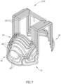
- FIG. 7 is a perspective illustration of a coil 210, which is an example of a circular coil 10 in accordance with embodiments of the present invention.
- Coil 210 is similar in construction to coil 110.
- third base portion group 18 of coil 210 has a different configuration than third base portion group 18 of coil 110.
- Third base portion 18 of coil 210 has a step configuration such as that shown in FIG. 2B .
- Coil 210 is used to stimulate lateral and medial prefrontal and orbitofrontal brain regions with a bilateral symmetry, and may be useful for treating, for example, Alzheimer's disease.
- FIG. 8 is a perspective illustration of a coil 310, which is an example of a circular coil 10 not in accordance with the claimed invention.
- Coil 310 includes a base portion 12 having a first base portion group 14 of multiple stimulating elements 20 and a second base portion group 16 of multiple stimulating elements 20. Coil 310 further includes a return portion 32 including return elements 40 corresponding to multiple stimulating elements 20.
- base portion 12 is configured to be positioned on an occipital section 108 of head 100 and return portion 32 is configured to be positioned on a top of parietal section 104 of head 100.
- base portion 12 may be positioned on a parietal section 104 and return portion may be positioned on an occipital portion 108 of head 100.
- First base portion group 14 is positioned at a lower portion of base portion 12 and second base portion group 16 is positioned higher than first base portion group 14 and is separated from first base portion group 14 by a distance D20.
- Return elements 40 of return portion 32 are contacting return elements 54, which are configured to contact and at least partially encircle portion of head 100.
- Connecting elements 52 are configured to contact the head as well.
- Coil 310 is used to stimulate occipital brain regions and regions in the cerebellum and may be useful for treating, for example, Parkinson's disease or migraine.
- the field distribution produced by coil 110 of FIG. 6 was measured in a human head phantom model.
- a probe was moved in three directions inside the phantom model using a displacement system with 1 mm resolution, and the field distribution of coil 110 was measured in the whole head model volume with 1 cm resolution.
- Axial and coronal field maps were produced.
- the field maps were superimposed on anatomical T1-weighted MRI coronal slices, to show the induced field in each anatomical brain region.
- FIG. 9 is an illustration of electric field distribution maps of coil 110 as measured in the human head phantom model.
- the field maps are shown for stimulator output set at 120% of threshold.
- the dark pixels indicate field magnitude above the threshold for neuronal activation.
- the threshold was set to 100 V/m, which is within the accepted range of thresholds required for hand motor activation.
- the intensity of stimulator power output used for drawing the maps representing the distribution of the electric field for coil 110 was set to the level required to obtain 120% of the neural motor threshold, at a depth of 1.5 cm, according to the approximate depth of hand motor cortex sites.
- Coil 110 is being used in a clinical trial studying the safety and efficacy of treating subjects suffering from Alzheimer's disease. Subjects receive 3 treatments per week for 4 weeks and 1 treatment /week for an additional 4 weeks. Assessments are performed at 1- 8 weeks and also after 16 weeks, i.e. 8 weeks after treatment completion. Analysis after 38 patients revealed that in the group treated with this coil at 10 Hz frequency there was improvement of 0.9 points at the end of the 8 week treatment period and additional improvement of 2.2 points at the 16 week follow up (total improvement of 3.1 points).
- the sham group showed no change at 8 weeks and a 1.1 point worsening at the 16 week follow up (total worsening of 1.1 points).
- the percentage of patients improving more than 8 points (responders) in the stimulation group was 18%, as opposed to 7% in the sham group. From the analysis of individual patient data, it appears that those subjects with more severe cognitive dysfunction at baseline may have experienced more improvement from the active treatment than those with less severe cognitive dysfunction at baseline. In the computerized Mindstreams Tr4 global cognitive score, a significant (p ⁇ 0.05) difference was observed in the improvement of the group receiving the treatment, relative to the changes measured in the sham control group in the 8 and 16 weeks time points.
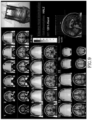
- FIG. 10 is an illustration of electric field distribution maps of coil 210 of FIG. 7 .
- the field distribution produced by coil 210 was measured using the same method as for FIG. 9 .
- the field maps are shown for stimulator output set at 120% of motor threshold. It can be seen that when placing the base portion of the coil over the prefrontal cortex, supra-threshold field is induced bilaterally in lateral prefrontal, medial prefrontal and orbitofrontal regions and in parietal regions.
- FIG. 11 is an illustration of electric field distribution maps of coil 310 of FIG. 8 .
- the field distribution produced by coil 310 was measured using the same method as for FIG. 9 .
- the field maps are shown for stimulator output set at 120% of motor threshold. It can be seen that when placing the base portion of the coil over the occipital cortex, supra-threshold field is induced bilaterally in occipital and cerebellar regions and in parietal regions.
Landscapes
- Health & Medical Sciences (AREA)
- Engineering & Computer Science (AREA)
- Biomedical Technology (AREA)
- Nuclear Medicine, Radiotherapy & Molecular Imaging (AREA)
- Radiology & Medical Imaging (AREA)
- Life Sciences & Earth Sciences (AREA)
- Animal Behavior & Ethology (AREA)
- General Health & Medical Sciences (AREA)
- Public Health (AREA)
- Veterinary Medicine (AREA)
- Neurology (AREA)
- Magnetic Treatment Devices (AREA)
- Magnetic Resonance Imaging Apparatus (AREA)
Description
- The present invention relates to a family of deep transcranial magnetic stimulation (TMS) coils, wherein a stimulating portion of the coils is at least partially circular and is configured to encircle at least a section of a body organ.
- Transcranial magnetic stimulation (TMS) is a noninvasive technique used to apply brief magnetic pulses to the brain, or to other human organs, and to thereby activate neuronal structures. The pulses are administered by passing high currents by a stimulator through an electromagnetic coil externally placed upon the patient (for example, placed on the scalp for brain treatment), inducing electrical currents in the underlying tissue, thereby producing a localized axonal depolarization. This technique has become a major tool in central nervous system research, as well as a potentially promising treatment option for various neurobehavioral and neurological disorders.
- Most known TMS coils stimulate superficial brain regions in the brain cortex, but the rate of decay of the induced magnetic and electric field as a function of distance from the coil is high. Hence the efficacy of affecting deeper neuronal structures is low. Stimulating deeper neuronal structures may be feasible if the intensity of the induced field is greatly increased. Yet operation at such increased intensity may increase the risk for seizures and for physiological damage to the tissue.
- A method for deep brain TMS with minimal stimulation of superficial regions is disclosed in
US Patent Number 7,407,478 , wherein deep brain stimulation is made possible while minimizing side effects. The device described therein includes a base and an extension portion, the base having individual windings for individual paths of current flow, and the extension portion designed so as to minimize unwanted stimulation of other regions of the brain. - However, there is a need for more specifically designed coils, which can target particular areas of the brain including deep neuronal structures with minimal effect on other brain regions. Examples of specific brain regions that may be desired to be stimulated are frontal lobe regions, occipital lobe regions, parietal lobe regions, right temporal regions and left temporal regions. Other examples may include activation of brain regions including deeper brain regions in a certain circumference of the brain, such as around a particular axial slice.
- Thus, there is a need for specifically designed coils for deep TMS which are location-specific for frontal lobe, occipital lobe, parietal lobe or temporal lobe brain regions. The coils must induce the desired distribution of the electric field in the brain, and simultaneously induce electric field intensity in the relevant brain tissue which will be feasible for neuronal stimulation with available TMS stimulators for most of the population. The stimulation intensity is routinely calibrated individually for each subject based on his or her motor threshold. Hence the coil efficiency must guarantee that the motor threshold and stimulation intensity for most of the relevant population is within an acceptable range with respect to available stimulators power outputs.
- The coils design must be efficient with respect to energy consumption, coil heating rate, compact size and ease of operation.
-
WO-A-2006134598 discloses a system including a helmet, a positioning portion, a stimulator and a cooling system. The helmet includes a coil for deep brain magnetic stimulation. The coil has a base portion, and return portions, which may include a protruding return portion and a contacting return portion. -
WO-A-0232504 WO 2012/155117 . - The invention provides a coil for transcranial magnetic stimulation as claimed in claim 1.
- The definition of the base relates to the functional elements of the coil carrying electric currents. However, there is no limitation regarding other elements of the device, such as mechanical components, cases and covers. Thus, certain elements of the base may be encased in a case containing additional coil elements such as return elements and other elements.
- The coil must induce the desired distribution of the electric field in the brain, and simultaneously induce an electric field intensity in the relevant brain tissue which is high enough to induce neuronal stimulation.
- Several features of the coil are important in order to achieve the above goals. These include:
- 1. Arrangement of the base portion elements. This arrangement must be optimized for each coil design and each specific goal. An interplay between two competing ideals may take place: Better depth penetration profile, namely higher relative electric field in the deeper target brain region compared to superficial region, on one hand, and higher absolute electric field intensity in the target brain region on the other hand. As a non-limiting example, suppose a base portion contains two groups of elements with a certain distance d between them. Increasing d will improve the depth penetration profile but may reduce the absolute field intensity in the target brain region. The intensity must be such that it will enable induction of the desired physiological effect in the target neural structures in the majority of the population with stimulators available in the market. Hence the distance d - as well as other configuration parameters - must be optimized for each coil design.
- 2. Location of the return portions relative to the base portion. The distance between the portions must be optimized for each design: Too short a distance will lead to reduction of the total induced electric field in the target brain region, due to the effect of the return elements. Too long a distance will require long connecting coil elements and their effect must be taken into account. Furthermore, the coil size must be optimized for easy location, navigation and placement over the head.
- 3. Location of the return portions relative to the brain. The return elements affect closer brain regions. The location of the return portions must consider their effect on any brain structure and the design must lead to minimal undesired side effects such as motor activation or pain.
- 4. The type of the return elements. Return elements may be either contacting or protruding as defined above. The ratio between contacting and protruding return elements is very important in various aspects and must be optimized for each specific coil design. In general, protruding elements induce electrostatic charge accumulation on the brain surface. This leads to reduction in the absolute electric field induced in the target brain regions, and also reduction in the relative intensity of the electric field in deeper brain regions compared to superficial regions. On the other hand, contacting elements may increase the effect in adjacent brain regions. Hence a delicate optimization must be performed in each case.
- 5. The distance of protruding return elements from the head, in coils containing protruding return elements. Longer distance reduces the direct effect of the return elements on the brain, but increases the charge accumulation due to the presence of longer non-tangential coil elements which are connected to the return elements and move them away from the head. A delicate optimization must be performed in each case to account for this effect.
- 6. The overall coil inductance. The number, length, configuration and packing parameters of the coil windings must be planned to lead to coil inductance in the desired range. Usually the desired range for TMS coils inductance is between 15 and 30 microHenri. Too high inductance may reduce coil efficacy, increase pulse width and is often associated with increased coil resistance, energy consumption and coil heating. Too small inductance may lead to fast rate of change of the electric current which may damage stimulator components.
- Unless otherwise defined, all technical and scientific terms used herein have the same meaning as commonly understood by one of ordinary skill in the art to which this invention belongs. Although materials similar or equivalent to those described herein can be used in the practice or testing of the present invention, suitable materials are described below. In case of conflict, the patent specification, including definitions, will control. In addition, the materials and examples are illustrative only and not intended to be limiting.
- The above and further advantages of the present invention may be better understood by referring to the following description in conjunction with the accompanying drawings in which:
-
FIG. 1 is a schematic illustration showing principles of stimulation for circular coils, in accordance with embodiments of the present invention; -
FIGS. 2A-2C are schematic illustrations of a base portion of the circular coil ofFIG. 1 , in accordance with embodiments of the present invention; -
FIGS. 3A and3B are schematic illustrations of base portions and return portions of the circular coil ofFIG. 1 , wherein the base and return portions have various configurations in accordance with embodiments of the present invention; -
FIG. 4 is an illustration of a return portion of the circular coil ofFIG. 1 , in accordance with embodiments of the present invention; -
FIG. 5 is an illustration of anatomical sections of a head; -
FIG. 6 is a perspective illustration of a coil which is an example of the circular coil ofFIG. 1 , in accordance with embodiments of the present invention; -
FIG. 7 is a perspective illustration of a coil which is an example of the circular coil ofFIG. 1 , in accordance with embodiments of the present invention; -
FIG. 8 is a perspective illustration of a coil which is an example of the circular coil ofFIG. 1 ; -
FIG. 9 is an illustration of electric field distribution maps of the coil ofFIG. 6 , as measured in a human head phantom model; -
FIG. 10 is an illustration of electric field distribution maps of the coil ofFIG. 7 as measured in a human head phantom model; and -
FIG. 11 is an illustration of electric field distribution maps of the coil ofFIG. 8 as measured in a human head phantom model. - It will be appreciated that for simplicity and clarity of illustration, elements shown in the drawings have not necessarily been drawn accurately or to scale. For example, the dimensions of some of the elements may be exaggerated relative to other elements for clarity or several physical components may be included in one functional block or element. Further, where considered appropriate, reference numerals may be repeated among the drawings to indicate corresponding or analogous elements. Moreover, some of the blocks depicted in the drawings may be combined into a single function.
- In the following detailed description, numerous specific details are set forth in order to provide a thorough understanding of the present invention. It will be understood by those of ordinary skill in the art that the present invention may be practiced without these specific details. In other instances, well-known methods, procedures, components and structures may not have been described in detail so as not to obscure the present invention.
- The present invention is directed to circular coils for deep TMS. The principles and operation of systems according to the present invention may be better understood with reference to the drawings and accompanying descriptions.
- Before explaining at least one embodiment of the present invention in detail, it is to be understood that the invention is not limited in its application to the details of construction and the arrangement of the components set forth in the following description or illustrated in the drawings. The invention is capable of other embodiments or of being practiced or carried out in various ways. Also, it is to be understood that the phraseology and terminology employed herein are for the purpose of description and should not be regarded as limiting.
- Reference is now made to
FIG. 1 , which is a schematic illustration showing principles of stimulation for circular coils, in accordance with embodiments of the present invention. In the embodiment shown inFIG. 1 , a schematic illustration of a circular coil depicts the elements of a circular coil in accordance with embodiments of the present invention, but does not depict the actual appearance of these elements. As shown inFIG. 1 , circular coil 10 includes abase portion 12 and areturn portion 32. A "circular coil" is defined as a coil whereinbase portion 12 encircles at least a portion of the body part and returnportion 32 encircles at least a portion of the body part.Base portion 12 andreturn portion 32 are depicted schematically inFIG. 1 as being semi-circular in shape. However, it should be readily apparent that other shapes are possible and may also be configured to encircle a body part in accordance with embodiments of the present invention, as will be described further hereinbelow - for example with reference toFIG. 2B .Base portion 12 includes multiplestimulating elements 20, depicted inFIG. 1 with arrows to illustrate the direction of electrical flow. Multiplestimulating elements 20 are shown as individual stimulating elements labeled first stimulatingelement 21, second stimulatingelement 22, third stimulatingelement 23, fourth stimulatingelement 24 and fifth stimulatingelement 25. It should be readily apparent that although five individual stimulating elements are shown inFIG. 1 schematically, circular coil 10 may include any suitable number of stimulating elements and are not limited to the amounts shown herein. Multiplestimulating elements 20 are substantially parallel to one another and are spaced apart from one another by distances, wherein first and secondstimulating elements stimulating elements stimulating elements stimulating elements elements 20 is substantially the same and is at least partially circular. That is, current flows through each of multiple stimulating elements in a curved or circular path, and multiplestimulating elements 20 are nested within one another, such that current flows in the same curved or circular path for each of stimulating elements 21-25 but separated by distances D1-D4. -
Return portion 32 includesmultiple return elements 40.Return elements 40 are depicted inFIG. 1 with arrows to illustrate the direction of electrical flow.Multiple return elements 40 are shown as individual return elements labeledfirst return element 41, corresponding to first stimulatingelement 21,second return element 42 corresponding to secondstimulating element 22,third return element 43 corresponding to thirdstimulating element 23,fourth return element 44 corresponding to fourth stimulatingelement 24 andfifth return element 45 corresponding to fifth stimulatingelement 25. It should be readily apparent that although five individual return elements are shown inFIG. 1 schematically, circular coil 10 may include any suitable number of return elements and are not limited to the amounts shown herein. Generally, the number ofreturn elements 40 corresponds to the number ofstimulating elements 20.Multiple return elements 40 are substantially parallel to one another and are spaced apart from one another by distances, wherein first andsecond return elements third return elements stimulating elements fifth return elements FIG. 1 that the direction of electrical flow forreturn elements 40 is a continuation of the circular path of electrical flow for stimulatingelements 20. Thus, if electrical flow for stimulatingelements 20 is in a clockwise direction, electrical flow forreturn elements 40 is also in a clockwise direction. If electrical flow for stimulatingelements 20 is in a counter-clockwise direction, electrical flow forreturn elements 40 is also in a counter-clockwise direction. In some embodiments, stimulatingelements 20 are electrically connected to returnelements 40 via connectingelements 52. As shown inFIG. 1 , connectingelements 52 carry electrical flow in the same clockwise or counterclockwise direction as stimulatingelements 20 and returnelements 40. - Reference is now made to
FIGS. 2A and 2B , which are schematic illustrations ofbase portion 12 in accordance with embodiments of the present invention. In one embodiment, as shown schematically inFIG. 2A ,base portion 12 includes a firstbase portion group 14 and a secondbase portion group 16. Firstbase portion group 14 may be separated from secondbase portion group 16 by a first base portion group distance D20. In some embodiments, additional base portion groups may be included as well, and separated from one another by additional base portion group distances. Each base portion group is defined as a group by one of several criteria, including location, spacing, and connection to return elements. For example, firstbase portion group 14 may include multiple stimulating elements each separated by equal distances D1 and D2, while secondbase portion group 16 may include multiple stimulating elements separated from one another by equal distances D3 and D4, wherein D1 and D2 are different than D3 and D4. In another embodiment, firstbase portion group 14 may be configured to be positioned on one portion of the head while secondbase portion group 16 may be configured to be positioned on another portion of the head. In yet another embodiment, firstbase portion group 14 may be connected to return elements which are in contact with the head and secondbase portion group 16 may be connected to return elements which are protruding from the head. It should be readily apparent that a direction of current flow in firstbase portion group 14 is substantially the same as a direction of current flow in secondbase portion group 16. - Reference is now made to
FIGS. 2B and2C , which are illustrations ofbase portion 12 in accordance with additional embodiments of the present invention. In the embodiments shown herein,base portion 12 includes multiplestimulating elements 20 which follow a modified curved path. For example, as shown inFIG. 2B , each of multiplestimulating elements 20 is configured in a step formation on two ends of a substantially semi-circular path. As another example, as shown inFIG. 2C , each of multiplestimulating elements 20 is configure in a partially outwardly curved and partially straight formation. Many other configurations are possible. In all of the embodiments, multiple stimulating elements are configured to conform to the shape of the body part, such as the head, and to encircle at least a portion of the body part. -
Return portion 32 may follow a similar pattern asbase portion 12 or may have a different configuration. For example, as shown inFIGS. 3A ,base portion 12 may include a step configuration whilereturn portion 32 may be semi-circular. As another example, as shown inFIG. 3B ,base portion 12 may include a firstbase portion group 14 having a first configuration and a secondbase portion group 16 having a second configuration, whilereturn portion 32 has a single configuration for all ofreturn elements 20. Alternatively, returnportion 32 may include multiple return portion groups. - Reference is now made to
FIG. 4 , which is an illustration of areturn portion 32, in accordance with embodiments of the present invention. Depicted inFIG. 4 is areturn portion 32 configured to be positioned on a side of the head, although it should be readily apparent that similar configurations ofreturn portion 32 may be used for other areas, such as a rear portion of the head, for example.Return elements 40 are shown at two different heights, wherein some ofreturn elements 40 are configured to be in contact with a body part and are on a same plane as base portion 12 (not shown). These returnelements 40 are referred to as contacting return elements 54. Some ofreturn elements 40 are configured to be protruding from the plane ofbase portion 12, and are referred to as protruding return elements 56. Protrudingreturn elements 52 may be at a vertical distance or a horizontal distance frombase portion 12, as long as protruding return elements 56 are configured to protrude from circular coil 10 such that they are configured not to contact the body part whichbase portion 12 is configured to contact. Thus, connectingelements 52 may be horizontal connecting elements 51 or may be vertical connecting elements 53 or may have additional configurations as needed to connectreturn portion 32 tobase portion 12. - In some embodiments, some of
multiple return elements 40 are contacting return elements 54 and some ofmultiple return elements 40 are protruding return elements 56. In examples not according to the claimed invention, all ofmultiple return elements 40 are contacting return elements 54. In some examples not according to the claimed invention, all ofmultiple return elements 40 are protruding return elements 56. Any combination of protruding and/or contacting return elements is possible. - Reference is now made to
FIG. 5 , which is an illustration of anatomical sections of ahead 100. For the purposes of illustrating the present invention,head 100 has four sections: afrontal section 102 at a front portion ofhead 100, aparietal section 104 to the rear offrontal section 102 and at a top portion ofhead 100, atemporal section 106 on the side ofhead 100 and anoccipital section 108 at a rear portion ofhead 100. Circular coil 10 is configured such thatbase portion 12 withstimulating elements 20 are positionable on and at least partially encircle a first section ofhead 100, and returnportion 32 withreturn elements 40 are positionable on and at least partially encircle a second section ofhead 100 which is different than the first section. Thus, for example,base portion 12 may be positioned onfrontal section 102 and returnportion 32 onparietal section 104. Alternatively,base portion 12 may be positioned onparietal section 104 and return portion positioned onoccipital section 108. In other examples baseportion 12 may be positioned onfrontal section 102 and returnportion 32 onoccipital section 108. In this way,base portion 12 stimulates a section of the brain, while return portion brings returning current back at a section which is remote from the stimulated section of the brain. In some embodiments, bothbase portion 12 andreturn portion 32 are adjacent to the head, and in some embodiments,base portion 12 is adjacent to the head whilereturn portion 32 is remote from the head. In some embodiments, connectingelements 52 are adjacent to the head and in other embodiments, connectingelements 52 are remote from the head. - Reference is now made to
FIG. 6 , which is a perspective illustration of acoil 110 which is an example of a circular coil 10 in accordance with embodiments of the present invention.Coil 110 includes abase portion 12 having a firstbase portion group 14 of multiplestimulating elements 20, a secondbase portion group 16 of multiplestimulating elements 20 and a thirdbase portion group 18 of multiplestimulating elements 20.Coil 110 further includes areturn portion 32 includingreturn elements 40 corresponding to multiplestimulating elements 20. Thus, returnportion 32 also includes a firstreturn portion group 34 corresponding to firstbase portion group 14, a secondreturn portion group 36 corresponding to secondbase portion group 16, and a thirdreturn portion group 38 corresponding to thirdbase portion group 18. In the embodiment shown herein,base portion 12 is configured to be positioned on afrontal section 102 ofhead 100 and returnportion 32 is configured to be positioned on anoccipital section 108 ofhead 100. Firstbase portion group 14 is positioned at a top portion ofbase portion 12, and firstreturn portion group 34, corresponding to firstbase portion group 14, is comprised of protruding return elements 56. Secondbase portion group 16 is positioned below firstbase portion group 14, and distances between multiplestimulating elements 20 of secondbase portion group 16 are greater than distances between multiplestimulating elements 20 offirst group 14. Secondreturn portion group 36 corresponding to firstbase portion group 16 is comprised of contacting return elements 54, which are configured to contact and at least partially encircle anoccipital section 108 ofhead 100. Thirdbase portion group 18 is positioned below first and secondbase portion groups stimulating elements 20 which have a different shape than multiplestimulating elements 20 of first and secondbase portion groups return portion group 38 corresponding to thirdbase portion group 18 is comprised of contacting return elements 54 and is positioned above secondreturn portion group 36. Thirdreturn portion group 38 is also configured to be positioned onoccipital section 108 ofhead 100.Connecting elements 52 include vertical connecting elements 53 and horizontal connecting elements 51 wherein horizontal connecting elements 51 protrude frombase portion 12. -
Coil 110 is used to stimulate lateral and medial prefrontal and orbitofrontal brain regions with a bilateral symmetry, and may be useful for treating, for example, Alzheimer's disease. - Reference is now made to
FIG. 7 , which is a perspective illustration of acoil 210, which is an example of a circular coil 10 in accordance with embodiments of the present invention.Coil 210 is similar in construction tocoil 110. However, thirdbase portion group 18 ofcoil 210 has a different configuration than thirdbase portion group 18 ofcoil 110.Third base portion 18 ofcoil 210 has a step configuration such as that shown inFIG. 2B . -
Coil 210 is used to stimulate lateral and medial prefrontal and orbitofrontal brain regions with a bilateral symmetry, and may be useful for treating, for example, Alzheimer's disease. - Reference is now made to
FIG. 8 , which is a perspective illustration of acoil 310, which is an example of a circular coil 10 not in accordance with the claimed invention. -
Coil 310 includes abase portion 12 having a firstbase portion group 14 of multiplestimulating elements 20 and a secondbase portion group 16 of multiplestimulating elements 20.Coil 310 further includes areturn portion 32 includingreturn elements 40 corresponding to multiplestimulating elements 20. In the embodiment shown herein,base portion 12 is configured to be positioned on anoccipital section 108 ofhead 100 and returnportion 32 is configured to be positioned on a top ofparietal section 104 ofhead 100. Alternatively,base portion 12 may be positioned on aparietal section 104 and return portion may be positioned on anoccipital portion 108 ofhead 100. Firstbase portion group 14 is positioned at a lower portion ofbase portion 12 and secondbase portion group 16 is positioned higher than firstbase portion group 14 and is separated from firstbase portion group 14 by a distance D20.Return elements 40 ofreturn portion 32 are contacting return elements 54, which are configured to contact and at least partially encircle portion ofhead 100.Connecting elements 52 are configured to contact the head as well. -
Coil 310 is used to stimulate occipital brain regions and regions in the cerebellum and may be useful for treating, for example, Parkinson's disease or migraine. - The field distribution produced by
coil 110 ofFIG. 6 was measured in a human head phantom model. A probe was moved in three directions inside the phantom model using a displacement system with 1 mm resolution, and the field distribution ofcoil 110 was measured in the whole head model volume with 1 cm resolution. Axial and coronal field maps were produced. The field maps were superimposed on anatomical T1-weighted MRI coronal slices, to show the induced field in each anatomical brain region. - Reference is now made to
FIG. 9 , which is an illustration of electric field distribution maps ofcoil 110 as measured in the human head phantom model. The field maps are shown for stimulator output set at 120% of threshold. The dark pixels indicate field magnitude above the threshold for neuronal activation. The threshold was set to 100 V/m, which is within the accepted range of thresholds required for hand motor activation. The intensity of stimulator power output used for drawing the maps representing the distribution of the electric field forcoil 110 was set to the level required to obtain 120% of the neural motor threshold, at a depth of 1.5 cm, according to the approximate depth of hand motor cortex sites. It can be seen that when placing the base portion ofcoil 110 over the prefrontal cortex, supra-threshold field is induced bilaterally in lateral prefrontal, medial prefrontal and orbitofrontal regions and in parietal regions.Coil 110 is being used in a clinical trial studying the safety and efficacy of treating subjects suffering from Alzheimer's disease. Subjects receive 3 treatments per week for 4 weeks and 1 treatment /week for an additional 4 weeks. Assessments are performed at 1- 8 weeks and also after 16 weeks, i.e. 8 weeks after treatment completion. Analysis after 38 patients revealed that in the group treated with this coil at 10 Hz frequency there was improvement of 0.9 points at the end of the 8 week treatment period and additional improvement of 2.2 points at the 16 week follow up (total improvement of 3.1 points). The sham group showed no change at 8 weeks and a 1.1 point worsening at the 16 week follow up (total worsening of 1.1 points). The percentage of patients improving more than 8 points (responders) in the stimulation group was 18%, as opposed to 7% in the sham group. From the analysis of individual patient data, it appears that those subjects with more severe cognitive dysfunction at baseline may have experienced more improvement from the active treatment than those with less severe cognitive dysfunction at baseline. In the computerized MindstreamsTr4 global cognitive score, a significant (p<0.05) difference was observed in the improvement of the group receiving the treatment, relative to the changes measured in the sham control group in the 8 and 16 weeks time points. - Reference is now made to
FIG. 10 , which is an illustration of electric field distribution maps ofcoil 210 ofFIG. 7 . The field distribution produced bycoil 210 was measured using the same method as forFIG. 9 . The field maps are shown for stimulator output set at 120% of motor threshold. It can be seen that when placing the base portion of the coil over the prefrontal cortex, supra-threshold field is induced bilaterally in lateral prefrontal, medial prefrontal and orbitofrontal regions and in parietal regions. - Reference is now made to
FIG. 11 , which is an illustration of electric field distribution maps ofcoil 310 ofFIG. 8 . The field distribution produced bycoil 310 was measured using the same method as forFIG. 9 . The field maps are shown for stimulator output set at 120% of motor threshold. It can be seen that when placing the base portion of the coil over the occipital cortex, supra-threshold field is induced bilaterally in occipital and cerebellar regions and in parietal regions. - It is appreciated that certain features of the invention, which are, for clarity, described in the context of separate embodiments, may also be provided in combination in a single embodiment. Conversely, various features of the invention, which are, for brevity, described in the context of a single embodiment, may also be provided separately or in any suitable sub-combination.
- While certain features of the present invention have been illustrated and described with reference to certain embodiments, modifications, substitutions, and changes will occur to those of ordinary skill in the art without departing from the scope of the present invention as defined by the claims.
Claims (2)
- A coil for magnetic stimulation of a head, the coil (10) comprising:a base portion (12) including multiple adjacent stimulating elements (20), said base portion (12) configured to encircle at least a portion of a first section of the head and to provide electrical flow in a substantially clockwise or counter-clockwise path;a protruding return portion (32) including multiple adjacent protruding return elements (56), said protruding return portion (32) configured to encircle and protrude from the head,and to provide electrical flow in a continuation of the clockwise or counter-clockwise circular path of said base portion (12), wherein all of said multiple stimulating elements of said base portion are configured to contact the head and wherein all of said multiple protruding return elements are configured to protrude from the head; anda contacting return portion (32) including multiple contacting return elements (54), said contacting return portion is configured to encircle and contact at least a portion of a second section of the head and to provide electrical flow in a continuation of the clockwise or counter-clockwise path of said base portion, characterised in that said first section is a frontal section of the head, and said second section is an occipital section of the head.
- The coil of claim 1, further comprising multiple first side connecting elements (52) positioned on a first base portion side and multiple second side connecting elements (52) positioned on a second base portion side, said multiple first side connecting elements (52) configured to carry electrical flow from said base portion to said return portion and said multiple second side connecting elements (52) configured to carry electrical flow from said return portion (32) to said base portion (12).
Applications Claiming Priority (3)
| Application Number | Priority Date | Filing Date | Title |
|---|---|---|---|
| US13/772,449 US9248308B2 (en) | 2013-02-21 | 2013-02-21 | Circular coils for deep transcranial magnetic stimulation |
| PCT/IB2014/059111 WO2014128631A1 (en) | 2013-02-21 | 2014-02-20 | Circular coils for deep transcranial magnetic stimulation |
| EP14710638.9A EP2958621B1 (en) | 2013-02-21 | 2014-02-20 | Circular coils for deep transcranial magnetic stimulation |
Related Parent Applications (1)
| Application Number | Title | Priority Date | Filing Date |
|---|---|---|---|
| EP14710638.9A Division EP2958621B1 (en) | 2013-02-21 | 2014-02-20 | Circular coils for deep transcranial magnetic stimulation |
Publications (2)
| Publication Number | Publication Date |
|---|---|
| EP3733241A1 EP3733241A1 (en) | 2020-11-04 |
| EP3733241B1 true EP3733241B1 (en) | 2024-10-09 |
Family
ID=50288197
Family Applications (2)
| Application Number | Title | Priority Date | Filing Date |
|---|---|---|---|
| EP20175550.1A Active EP3733241B1 (en) | 2013-02-21 | 2014-02-20 | Coil for magnetic stimulation of a body part |
| EP14710638.9A Active EP2958621B1 (en) | 2013-02-21 | 2014-02-20 | Circular coils for deep transcranial magnetic stimulation |
Family Applications After (1)
| Application Number | Title | Priority Date | Filing Date |
|---|---|---|---|
| EP14710638.9A Active EP2958621B1 (en) | 2013-02-21 | 2014-02-20 | Circular coils for deep transcranial magnetic stimulation |
Country Status (8)
| Country | Link |
|---|---|
| US (1) | US9248308B2 (en) |
| EP (2) | EP3733241B1 (en) |
| JP (1) | JP6742728B2 (en) |
| AU (1) | AU2014220309B2 (en) |
| CA (1) | CA2902057C (en) |
| ES (1) | ES2812536T3 (en) |
| IL (2) | IL240725B (en) |
| WO (1) | WO2014128631A1 (en) |
Families Citing this family (28)
| Publication number | Priority date | Publication date | Assignee | Title |
|---|---|---|---|---|
| US20150099921A1 (en) * | 2008-11-26 | 2015-04-09 | M. Bret Schneider | Treatment of degenerative brain disorders using transcranial magnetic stimulation |
| ES2940892T3 (en) * | 2015-04-02 | 2023-05-12 | Univ Tokyo | Coil device for use in transcranial magnetic stimulation device |
| US10695575B1 (en) | 2016-05-10 | 2020-06-30 | Btl Medical Technologies S.R.O. | Aesthetic method of biological structure treatment by magnetic field |
| US20180001107A1 (en) | 2016-07-01 | 2018-01-04 | Btl Holdings Limited | Aesthetic method of biological structure treatment by magnetic field |
| US11266850B2 (en) | 2015-07-01 | 2022-03-08 | Btl Healthcare Technologies A.S. | High power time varying magnetic field therapy |
| US11247039B2 (en) | 2016-05-03 | 2022-02-15 | Btl Healthcare Technologies A.S. | Device including RF source of energy and vacuum system |
| US11464993B2 (en) | 2016-05-03 | 2022-10-11 | Btl Healthcare Technologies A.S. | Device including RF source of energy and vacuum system |
| US11534619B2 (en) | 2016-05-10 | 2022-12-27 | Btl Medical Solutions A.S. | Aesthetic method of biological structure treatment by magnetic field |
| US12654023B2 (en) | 2016-05-10 | 2026-06-16 | Btl Medical Solutions A.S. | Aesthetic method of biological structure treatment by magnetic field |
| US10583287B2 (en) | 2016-05-23 | 2020-03-10 | Btl Medical Technologies S.R.O. | Systems and methods for tissue treatment |
| US10556122B1 (en) | 2016-07-01 | 2020-02-11 | Btl Medical Technologies S.R.O. | Aesthetic method of biological structure treatment by magnetic field |
| US11141219B1 (en) | 2016-08-16 | 2021-10-12 | BTL Healthcare Technologies, a.s. | Self-operating belt |
| WO2018078619A1 (en) | 2016-10-25 | 2018-05-03 | Brainsway Ltd | Apparatus and methods for predicting therapy outcome |
| WO2018136429A1 (en) * | 2017-01-19 | 2018-07-26 | The Board Of Trustees Of The Leland Stanford Junior University | Method of deep stimulation transcranial magnetic stimulation |
| CN110234389B (en) | 2017-02-02 | 2023-11-03 | 福禄神经学公司 | Headset for transcranial direct current stimulation of TDCS and system including the same |
| CA3090358A1 (en) * | 2018-02-05 | 2019-08-08 | Brainsway Ltd. | Electromagnetic coil assembly |
| US11000693B2 (en) | 2018-02-20 | 2021-05-11 | Neuronetics, Inc. | Magnetic stimulation coils and ferromagnetic components for treatment and diagnostic procedures |
| US12156689B2 (en) | 2019-04-11 | 2024-12-03 | Btl Medical Solutions A.S. | Methods and devices for aesthetic treatment of biological structures by radiofrequency and magnetic energy |
| US12558146B2 (en) | 2019-04-11 | 2026-02-24 | Btl Medical Solutions A.S. | Methods and devices for aesthetic treatment of biological structures by radiofrequency and magnetic energy |
| EP4691400A3 (en) | 2019-04-11 | 2026-04-22 | BTL Medical Solutions a.s. | Methods and devices for treatment of biological structure by radiofrequency energy |
| US12611545B2 (en) | 2020-05-04 | 2026-04-28 | Btl Healthcare Technologies A.S. | Device and method for unattended treatment of a patient |
| US11878167B2 (en) | 2020-05-04 | 2024-01-23 | Btl Healthcare Technologies A.S. | Device and method for unattended treatment of a patient |
| HRP20250160T1 (en) | 2020-05-04 | 2025-03-28 | Btl Healthcare Technologies A.S. | DEVICE FOR TREATING PATIENTS WITHOUT THE PRESENCE OF A DOCTOR |
| CA3260012A1 (en) | 2021-10-13 | 2023-04-20 | Btl Medical Solutions A.S. | Devices for aesthetic treatment of biological structures by radiofrequency and magnetic energy |
| US11896816B2 (en) | 2021-11-03 | 2024-02-13 | Btl Healthcare Technologies A.S. | Device and method for unattended treatment of a patient |
| CN120322272A (en) | 2022-10-12 | 2025-07-15 | Ampa公司 | Neuronavigation transcranial brain energy delivery and detection system and method |
| CN117482400B (en) * | 2023-12-27 | 2024-03-12 | 成都理工大学 | Time domain interferometry feature stimulation array and system for craniocerebral depth focus stimulation |
| US20260097226A1 (en) | 2024-10-08 | 2026-04-09 | Btl Medical Solutions A.S. | Devices and methods for application of a magnetic field to the nervous system |
Citations (1)
| Publication number | Priority date | Publication date | Assignee | Title |
|---|---|---|---|---|
| WO2012155117A1 (en) * | 2011-05-11 | 2012-11-15 | Covalin, Alejandro | Headache-treatment device with gel dispensing kit and method |
Family Cites Families (29)
| Publication number | Priority date | Publication date | Assignee | Title |
|---|---|---|---|---|
| US5116304A (en) | 1987-01-28 | 1992-05-26 | Cadwell Industries, Inc. | Magnetic stimulator with skullcap-shaped coil |
| US4994015A (en) | 1987-09-14 | 1991-02-19 | Cadwell Industries, Inc. | Magnetic stimulator coils |
| EP0361137A1 (en) | 1988-09-16 | 1990-04-04 | Siemens Aktiengesellschaft | Magnetometer device with a cryostat for the measurement of weak magnetic fields |
| US5078674A (en) | 1989-02-10 | 1992-01-07 | Cadwll Industries, Inc. | Magnetic stimulator coils |
| US5506200A (en) | 1992-02-06 | 1996-04-09 | Biomagnetic Technologies, Inc. | Compact superconducting magnetometer having no vacuum insulation |
| US5442289A (en) | 1989-07-31 | 1995-08-15 | Biomagnetic Technologies, Inc. | Biomagnetometer having flexible sensor |
| US5158932A (en) | 1989-07-31 | 1992-10-27 | Biomagnetic Technologies, Inc. | Superconducting biomagnetometer with inductively coupled pickup coil |
| FI89131C (en) | 1990-12-21 | 1993-08-25 | Neuromag Oy | MAGNETOMETER DETECTOR OVER DERAS MONTAGE I EN FLORKANALIG ANORDNING FOER MAETNING AV MAENSKANS HJAERNFUNKTIONER ALSTRANDE MAGNETFAELT |
| GB2278783A (en) | 1993-06-11 | 1994-12-14 | Daniel Shellon Gluck | Method of magnetically stimulating neural cells |
| EP0906138A1 (en) | 1996-04-26 | 1999-04-07 | Zentralinstitut für Biomedizinische Technik der Universität Ulm | Method and apparatus for focused neuromagnetic stimulation and detection |
| JP2000504966A (en) | 1996-08-15 | 2000-04-25 | ニュートナス,インコーポレーテッド | Skull brain stimulation |
| US6179771B1 (en) | 1998-04-21 | 2001-01-30 | Siemens Aktiengesellschaft | Coil arrangement for transcranial magnetic stimulation |
| US7062330B1 (en) | 1998-10-26 | 2006-06-13 | Boveja Birinder R | Electrical stimulation adjunct (Add-ON) therapy for urinary incontinence and urological disorders using implanted lead stimulus-receiver and an external pulse generator |
| US6402678B1 (en) | 2000-07-31 | 2002-06-11 | Neuralieve, Inc. | Means and method for the treatment of migraine headaches |
| IL155320A0 (en) | 2000-10-20 | 2003-11-23 | Us Gov Health & Human Serv | Coil for magnetic stimulation |
| AU2002254777B2 (en) | 2001-05-04 | 2005-02-03 | Board Of Regents, The University Of Texas System | Apparatus and methods for delivery of transcranial magnetic stimulation |
| US20050154426A1 (en) | 2002-05-09 | 2005-07-14 | Boveja Birinder R. | Method and system for providing therapy for neuropsychiatric and neurological disorders utilizing transcranical magnetic stimulation and pulsed electrical vagus nerve(s) stimulation |
| US7153256B2 (en) | 2003-03-07 | 2006-12-26 | Neuronetics, Inc. | Reducing discomfort caused by electrical stimulation |
| US7520848B2 (en) | 2004-04-09 | 2009-04-21 | The Board Of Trustees Of The Leland Stanford Junior University | Robotic apparatus for targeting and producing deep, focused transcranial magnetic stimulation |
| US7857746B2 (en) * | 2004-10-29 | 2010-12-28 | Nueronetics, Inc. | System and method to reduce discomfort using nerve stimulation |
| US7976451B2 (en) | 2005-06-16 | 2011-07-12 | The United States Of America As Represented By The Department Of Health And Human Services | Transcranial magnetic stimulation system and methods |
| US7824324B2 (en) | 2005-07-27 | 2010-11-02 | Neuronetics, Inc. | Magnetic core for medical procedures |
| US8267850B2 (en) | 2007-11-27 | 2012-09-18 | Cervel Neurotech, Inc. | Transcranial magnet stimulation of deep brain targets |
| US7753836B2 (en) | 2006-06-15 | 2010-07-13 | The Trustees Of Columbia University In The City Of New York | Systems and methods for inducing electric field pulses in a body organ |
| US7998053B2 (en) | 2006-08-30 | 2011-08-16 | Nexstim Oy | Transcranial magnetic stimulation induction coil device and method of manufacture |
| US8801589B2 (en) * | 2008-08-04 | 2014-08-12 | The Trustees Of Columbia University In The City Of New York | Methods, apparatus, and systems for magnetic stimulation |
| US9180305B2 (en) | 2008-12-11 | 2015-11-10 | Yeda Research & Development Co. Ltd. At The Weizmann Institute Of Science | Systems and methods for controlling electric field pulse parameters using transcranial magnetic stimulation |
| EP2384223A4 (en) * | 2009-01-07 | 2014-06-18 | Cervel Neurotech Inc | Shaped coils for transcranial magnetic stimulation |
| WO2010113164A1 (en) | 2009-04-03 | 2010-10-07 | Neuronix Ltd. | Method and system for neurological treatment |
-
2013
- 2013-02-21 US US13/772,449 patent/US9248308B2/en active Active
-
2014
- 2014-02-20 EP EP20175550.1A patent/EP3733241B1/en active Active
- 2014-02-20 AU AU2014220309A patent/AU2014220309B2/en active Active
- 2014-02-20 EP EP14710638.9A patent/EP2958621B1/en active Active
- 2014-02-20 JP JP2015558586A patent/JP6742728B2/en active Active
- 2014-02-20 WO PCT/IB2014/059111 patent/WO2014128631A1/en not_active Ceased
- 2014-02-20 ES ES14710638T patent/ES2812536T3/en active Active
- 2014-02-20 CA CA2902057A patent/CA2902057C/en active Active
-
2015
- 2015-08-20 IL IL240725A patent/IL240725B/en active IP Right Grant
-
2019
- 2019-08-05 IL IL268508A patent/IL268508B/en active IP Right Grant
Patent Citations (1)
| Publication number | Priority date | Publication date | Assignee | Title |
|---|---|---|---|---|
| WO2012155117A1 (en) * | 2011-05-11 | 2012-11-15 | Covalin, Alejandro | Headache-treatment device with gel dispensing kit and method |
Also Published As
| Publication number | Publication date |
|---|---|
| EP2958621A1 (en) | 2015-12-30 |
| US9248308B2 (en) | 2016-02-02 |
| IL240725A0 (en) | 2015-10-29 |
| CA2902057A1 (en) | 2014-08-28 |
| JP2016507323A (en) | 2016-03-10 |
| IL268508B (en) | 2020-11-30 |
| EP2958621B1 (en) | 2020-05-27 |
| IL240725B (en) | 2019-08-29 |
| JP6742728B2 (en) | 2020-08-19 |
| AU2014220309B2 (en) | 2018-03-01 |
| US20140235926A1 (en) | 2014-08-21 |
| WO2014128631A1 (en) | 2014-08-28 |
| AU2014220309A1 (en) | 2015-10-15 |
| EP3733241A1 (en) | 2020-11-04 |
| ES2812536T3 (en) | 2021-03-17 |
| CA2902057C (en) | 2021-03-30 |
| IL268508A (en) | 2019-09-26 |
Similar Documents
| Publication | Publication Date | Title |
|---|---|---|
| EP2958621B1 (en) | Circular coils for deep transcranial magnetic stimulation | |
| US9808642B2 (en) | Circular coils for deep transcranial magnetic stimulation | |
| EP2958622B1 (en) | Unilateral coils for deep transcranial magnetic stimulation | |
| US10625091B2 (en) | Central base coils for deep transcranial magnetic stimulation | |
| US9254394B2 (en) | Central base coils for deep transcranial magnetic stimulation | |
| AU2002229129B9 (en) | Coil for magnetic stimulation |
Legal Events
| Date | Code | Title | Description |
|---|---|---|---|
| PUAI | Public reference made under article 153(3) epc to a published international application that has entered the european phase |
Free format text: ORIGINAL CODE: 0009012 |
|
| STAA | Information on the status of an ep patent application or granted ep patent |
Free format text: STATUS: THE APPLICATION HAS BEEN PUBLISHED |
|
| AC | Divisional application: reference to earlier application |
Ref document number: 2958621 Country of ref document: EP Kind code of ref document: P |
|
| AK | Designated contracting states |
Kind code of ref document: A1 Designated state(s): AL AT BE BG CH CY CZ DE DK EE ES FI FR GB GR HR HU IE IS IT LI LT LU LV MC MK MT NL NO PL PT RO RS SE SI SK SM TR |
|
| STAA | Information on the status of an ep patent application or granted ep patent |
Free format text: STATUS: REQUEST FOR EXAMINATION WAS MADE |
|
| 17P | Request for examination filed |
Effective date: 20210504 |
|
| RBV | Designated contracting states (corrected) |
Designated state(s): AL AT BE BG CH CY CZ DE DK EE ES FI FR GB GR HR HU IE IS IT LI LT LU LV MC MK MT NL NO PL PT RO RS SE SI SK SM TR |
|
| STAA | Information on the status of an ep patent application or granted ep patent |
Free format text: STATUS: EXAMINATION IS IN PROGRESS |
|
| 17Q | First examination report despatched |
Effective date: 20230831 |
|
| GRAP | Despatch of communication of intention to grant a patent |
Free format text: ORIGINAL CODE: EPIDOSNIGR1 |
|
| STAA | Information on the status of an ep patent application or granted ep patent |
Free format text: STATUS: GRANT OF PATENT IS INTENDED |
|
| INTG | Intention to grant announced |
Effective date: 20240430 |
|
| GRAS | Grant fee paid |
Free format text: ORIGINAL CODE: EPIDOSNIGR3 |
|
| GRAA | (expected) grant |
Free format text: ORIGINAL CODE: 0009210 |
|
| STAA | Information on the status of an ep patent application or granted ep patent |
Free format text: STATUS: THE PATENT HAS BEEN GRANTED |
|
| AC | Divisional application: reference to earlier application |
Ref document number: 2958621 Country of ref document: EP Kind code of ref document: P |
|
| AK | Designated contracting states |
Kind code of ref document: B1 Designated state(s): AL AT BE BG CH CY CZ DE DK EE ES FI FR GB GR HR HU IE IS IT LI LT LU LV MC MK MT NL NO PL PT RO RS SE SI SK SM TR |
|
| REG | Reference to a national code |
Ref country code: CH Ref legal event code: EP |
|
| REG | Reference to a national code |
Ref country code: DE Ref legal event code: R096 Ref document number: 602014091015 Country of ref document: DE |
|
| REG | Reference to a national code |
Ref country code: IE Ref legal event code: FG4D |
|
| REG | Reference to a national code |
Ref country code: LT Ref legal event code: MG9D |
|
| REG | Reference to a national code |
Ref country code: NL Ref legal event code: MP Effective date: 20241009 |
|
| REG | Reference to a national code |
Ref country code: AT Ref legal event code: MK05 Ref document number: 1729939 Country of ref document: AT Kind code of ref document: T Effective date: 20241009 |
|
| PG25 | Lapsed in a contracting state [announced via postgrant information from national office to epo] |
Ref country code: NL Free format text: LAPSE BECAUSE OF FAILURE TO SUBMIT A TRANSLATION OF THE DESCRIPTION OR TO PAY THE FEE WITHIN THE PRESCRIBED TIME-LIMIT Effective date: 20241009 |
|
| PG25 | Lapsed in a contracting state [announced via postgrant information from national office to epo] |
Ref country code: NL Free format text: LAPSE BECAUSE OF FAILURE TO SUBMIT A TRANSLATION OF THE DESCRIPTION OR TO PAY THE FEE WITHIN THE PRESCRIBED TIME-LIMIT Effective date: 20241009 |
|
| PG25 | Lapsed in a contracting state [announced via postgrant information from national office to epo] |
Ref country code: IS Free format text: LAPSE BECAUSE OF FAILURE TO SUBMIT A TRANSLATION OF THE DESCRIPTION OR TO PAY THE FEE WITHIN THE PRESCRIBED TIME-LIMIT Effective date: 20250209 Ref country code: PT Free format text: LAPSE BECAUSE OF FAILURE TO SUBMIT A TRANSLATION OF THE DESCRIPTION OR TO PAY THE FEE WITHIN THE PRESCRIBED TIME-LIMIT Effective date: 20250210 Ref country code: HR Free format text: LAPSE BECAUSE OF FAILURE TO SUBMIT A TRANSLATION OF THE DESCRIPTION OR TO PAY THE FEE WITHIN THE PRESCRIBED TIME-LIMIT Effective date: 20241009 |
|
| PG25 | Lapsed in a contracting state [announced via postgrant information from national office to epo] |
Ref country code: FI Free format text: LAPSE BECAUSE OF FAILURE TO SUBMIT A TRANSLATION OF THE DESCRIPTION OR TO PAY THE FEE WITHIN THE PRESCRIBED TIME-LIMIT Effective date: 20241009 |
|
| PG25 | Lapsed in a contracting state [announced via postgrant information from national office to epo] |
Ref country code: BG Free format text: LAPSE BECAUSE OF FAILURE TO SUBMIT A TRANSLATION OF THE DESCRIPTION OR TO PAY THE FEE WITHIN THE PRESCRIBED TIME-LIMIT Effective date: 20241009 |
|
| PG25 | Lapsed in a contracting state [announced via postgrant information from national office to epo] |
Ref country code: ES Free format text: LAPSE BECAUSE OF FAILURE TO SUBMIT A TRANSLATION OF THE DESCRIPTION OR TO PAY THE FEE WITHIN THE PRESCRIBED TIME-LIMIT Effective date: 20241009 |
|
| PG25 | Lapsed in a contracting state [announced via postgrant information from national office to epo] |
Ref country code: NO Free format text: LAPSE BECAUSE OF FAILURE TO SUBMIT A TRANSLATION OF THE DESCRIPTION OR TO PAY THE FEE WITHIN THE PRESCRIBED TIME-LIMIT Effective date: 20250109 |
|
| PG25 | Lapsed in a contracting state [announced via postgrant information from national office to epo] |
Ref country code: LV Free format text: LAPSE BECAUSE OF FAILURE TO SUBMIT A TRANSLATION OF THE DESCRIPTION OR TO PAY THE FEE WITHIN THE PRESCRIBED TIME-LIMIT Effective date: 20241009 Ref country code: GR Free format text: LAPSE BECAUSE OF FAILURE TO SUBMIT A TRANSLATION OF THE DESCRIPTION OR TO PAY THE FEE WITHIN THE PRESCRIBED TIME-LIMIT Effective date: 20250110 Ref country code: AT Free format text: LAPSE BECAUSE OF FAILURE TO SUBMIT A TRANSLATION OF THE DESCRIPTION OR TO PAY THE FEE WITHIN THE PRESCRIBED TIME-LIMIT Effective date: 20241009 |
|
| PG25 | Lapsed in a contracting state [announced via postgrant information from national office to epo] |
Ref country code: PL Free format text: LAPSE BECAUSE OF FAILURE TO SUBMIT A TRANSLATION OF THE DESCRIPTION OR TO PAY THE FEE WITHIN THE PRESCRIBED TIME-LIMIT Effective date: 20241009 |
|
| PG25 | Lapsed in a contracting state [announced via postgrant information from national office to epo] |
Ref country code: RS Free format text: LAPSE BECAUSE OF FAILURE TO SUBMIT A TRANSLATION OF THE DESCRIPTION OR TO PAY THE FEE WITHIN THE PRESCRIBED TIME-LIMIT Effective date: 20250109 |
|
| PG25 | Lapsed in a contracting state [announced via postgrant information from national office to epo] |
Ref country code: SM Free format text: LAPSE BECAUSE OF FAILURE TO SUBMIT A TRANSLATION OF THE DESCRIPTION OR TO PAY THE FEE WITHIN THE PRESCRIBED TIME-LIMIT Effective date: 20241009 |
|
| PG25 | Lapsed in a contracting state [announced via postgrant information from national office to epo] |
Ref country code: DK Free format text: LAPSE BECAUSE OF FAILURE TO SUBMIT A TRANSLATION OF THE DESCRIPTION OR TO PAY THE FEE WITHIN THE PRESCRIBED TIME-LIMIT Effective date: 20241009 |
|
| REG | Reference to a national code |
Ref country code: DE Ref legal event code: R097 Ref document number: 602014091015 Country of ref document: DE |
|
| PG25 | Lapsed in a contracting state [announced via postgrant information from national office to epo] |
Ref country code: EE Free format text: LAPSE BECAUSE OF FAILURE TO SUBMIT A TRANSLATION OF THE DESCRIPTION OR TO PAY THE FEE WITHIN THE PRESCRIBED TIME-LIMIT Effective date: 20241009 |
|
| PG25 | Lapsed in a contracting state [announced via postgrant information from national office to epo] |
Ref country code: RO Free format text: LAPSE BECAUSE OF FAILURE TO SUBMIT A TRANSLATION OF THE DESCRIPTION OR TO PAY THE FEE WITHIN THE PRESCRIBED TIME-LIMIT Effective date: 20241009 |
|
| PG25 | Lapsed in a contracting state [announced via postgrant information from national office to epo] |
Ref country code: SK Free format text: LAPSE BECAUSE OF FAILURE TO SUBMIT A TRANSLATION OF THE DESCRIPTION OR TO PAY THE FEE WITHIN THE PRESCRIBED TIME-LIMIT Effective date: 20241009 |
|
| PG25 | Lapsed in a contracting state [announced via postgrant information from national office to epo] |
Ref country code: CZ Free format text: LAPSE BECAUSE OF FAILURE TO SUBMIT A TRANSLATION OF THE DESCRIPTION OR TO PAY THE FEE WITHIN THE PRESCRIBED TIME-LIMIT Effective date: 20241009 |
|
| PLBE | No opposition filed within time limit |
Free format text: ORIGINAL CODE: 0009261 |
|
| STAA | Information on the status of an ep patent application or granted ep patent |
Free format text: STATUS: NO OPPOSITION FILED WITHIN TIME LIMIT |
|
| PG25 | Lapsed in a contracting state [announced via postgrant information from national office to epo] |
Ref country code: SE Free format text: LAPSE BECAUSE OF FAILURE TO SUBMIT A TRANSLATION OF THE DESCRIPTION OR TO PAY THE FEE WITHIN THE PRESCRIBED TIME-LIMIT Effective date: 20241009 |
|
| PG25 | Lapsed in a contracting state [announced via postgrant information from national office to epo] |
Ref country code: MC Free format text: LAPSE BECAUSE OF FAILURE TO SUBMIT A TRANSLATION OF THE DESCRIPTION OR TO PAY THE FEE WITHIN THE PRESCRIBED TIME-LIMIT Effective date: 20241009 |
|
| 26N | No opposition filed |
Effective date: 20250710 |
|
| REG | Reference to a national code |
Ref country code: CH Ref legal event code: PL |
|
| PG25 | Lapsed in a contracting state [announced via postgrant information from national office to epo] |
Ref country code: LU Free format text: LAPSE BECAUSE OF NON-PAYMENT OF DUE FEES Effective date: 20250220 |
|
| PG25 | Lapsed in a contracting state [announced via postgrant information from national office to epo] |
Ref country code: CH Free format text: LAPSE BECAUSE OF NON-PAYMENT OF DUE FEES Effective date: 20250228 |
|
| REG | Reference to a national code |
Ref country code: BE Ref legal event code: MM Effective date: 20250228 |
|
| PG25 | Lapsed in a contracting state [announced via postgrant information from national office to epo] |
Ref country code: BE Free format text: LAPSE BECAUSE OF NON-PAYMENT OF DUE FEES Effective date: 20250228 |
|
| PG25 | Lapsed in a contracting state [announced via postgrant information from national office to epo] |
Ref country code: IE Free format text: LAPSE BECAUSE OF NON-PAYMENT OF DUE FEES Effective date: 20250220 |
|
| PGFP | Annual fee paid to national office [announced via postgrant information from national office to epo] |
Ref country code: GB Payment date: 20260128 Year of fee payment: 13 |
|
| PGFP | Annual fee paid to national office [announced via postgrant information from national office to epo] |
Ref country code: DE Payment date: 20260121 Year of fee payment: 13 |
|
| PGFP | Annual fee paid to national office [announced via postgrant information from national office to epo] |
Ref country code: IT Payment date: 20260128 Year of fee payment: 13 |
|
| PGFP | Annual fee paid to national office [announced via postgrant information from national office to epo] |
Ref country code: FR Payment date: 20260121 Year of fee payment: 13 |
|
| PG25 | Lapsed in a contracting state [announced via postgrant information from national office to epo] |
Ref country code: CY Free format text: LAPSE BECAUSE OF FAILURE TO SUBMIT A TRANSLATION OF THE DESCRIPTION OR TO PAY THE FEE WITHIN THE PRESCRIBED TIME-LIMIT Effective date: 20241009 |
|
| PG25 | Lapsed in a contracting state [announced via postgrant information from national office to epo] |
Ref country code: LT Free format text: LAPSE BECAUSE OF FAILURE TO SUBMIT A TRANSLATION OF THE DESCRIPTION OR TO PAY THE FEE WITHIN THE PRESCRIBED TIME-LIMIT Effective date: 20241009 |
|
| PG25 | Lapsed in a contracting state [announced via postgrant information from national office to epo] |
Ref country code: TR Free format text: LAPSE BECAUSE OF FAILURE TO SUBMIT A TRANSLATION OF THE DESCRIPTION OR TO PAY THE FEE WITHIN THE PRESCRIBED TIME-LIMIT Effective date: 20241009 |