EP0361137A1 - Magnetometer device with a cryostat for the measurement of weak magnetic fields - Google Patents
Magnetometer device with a cryostat for the measurement of weak magnetic fields Download PDFInfo
- Publication number
- EP0361137A1 EP0361137A1 EP89116322A EP89116322A EP0361137A1 EP 0361137 A1 EP0361137 A1 EP 0361137A1 EP 89116322 A EP89116322 A EP 89116322A EP 89116322 A EP89116322 A EP 89116322A EP 0361137 A1 EP0361137 A1 EP 0361137A1
- Authority
- EP
- European Patent Office
- Prior art keywords
- neck
- interior
- gradiometers
- dewar vessel
- gaseous refrigerant
- Prior art date
- Legal status (The legal status is an assumption and is not a legal conclusion. Google has not performed a legal analysis and makes no representation as to the accuracy of the status listed.)
- Withdrawn
Links
- 238000005259 measurement Methods 0.000 title abstract description 3
- 241000238366 Cephalopoda Species 0.000 claims abstract description 22
- 239000007788 liquid Substances 0.000 claims abstract description 10
- 239000002826 coolant Substances 0.000 claims abstract description 6
- 239000003507 refrigerant Substances 0.000 claims description 31
- 239000004020 conductor Substances 0.000 claims description 8
- 239000004033 plastic Substances 0.000 claims description 6
- 229920003023 plastic Polymers 0.000 claims description 6
- 238000009423 ventilation Methods 0.000 claims description 3
- 238000005452 bending Methods 0.000 claims description 2
- 239000011521 glass Substances 0.000 claims description 2
- 229920006267 polyester film Polymers 0.000 claims description 2
- 239000007789 gas Substances 0.000 description 23
- 238000001816 cooling Methods 0.000 description 7
- 239000001307 helium Substances 0.000 description 4
- 229910052734 helium Inorganic materials 0.000 description 4
- SWQJXJOGLNCZEY-UHFFFAOYSA-N helium atom Chemical compound [He] SWQJXJOGLNCZEY-UHFFFAOYSA-N 0.000 description 4
- 210000004556 brain Anatomy 0.000 description 3
- 230000008878 coupling Effects 0.000 description 2
- 238000010168 coupling process Methods 0.000 description 2
- 238000005859 coupling reaction Methods 0.000 description 2
- 230000004907 flux Effects 0.000 description 2
- 230000005855 radiation Effects 0.000 description 2
- 230000015556 catabolic process Effects 0.000 description 1
- 230000005670 electromagnetic radiation Effects 0.000 description 1
- 238000005516 engineering process Methods 0.000 description 1
- 239000011152 fibreglass Substances 0.000 description 1
- 239000006260 foam Substances 0.000 description 1
- 239000003365 glass fiber Substances 0.000 description 1
- 238000003780 insertion Methods 0.000 description 1
- 230000037431 insertion Effects 0.000 description 1
- 238000002582 magnetoencephalography Methods 0.000 description 1
- 239000000463 material Substances 0.000 description 1
Images

Classifications
-
- A—HUMAN NECESSITIES
- A61—MEDICAL OR VETERINARY SCIENCE; HYGIENE
- A61B—DIAGNOSIS; SURGERY; IDENTIFICATION
- A61B5/00—Measuring for diagnostic purposes; Identification of persons
- A61B5/24—Detecting, measuring or recording bioelectric or biomagnetic signals of the body or parts thereof
- A61B5/242—Detecting biomagnetic fields, e.g. magnetic fields produced by bioelectric currents
-
- F—MECHANICAL ENGINEERING; LIGHTING; HEATING; WEAPONS; BLASTING
- F17—STORING OR DISTRIBUTING GASES OR LIQUIDS
- F17C—VESSELS FOR CONTAINING OR STORING COMPRESSED, LIQUEFIED OR SOLIDIFIED GASES; FIXED-CAPACITY GAS-HOLDERS; FILLING VESSELS WITH, OR DISCHARGING FROM VESSELS, COMPRESSED, LIQUEFIED, OR SOLIDIFIED GASES
- F17C3/00—Vessels not under pressure
- F17C3/02—Vessels not under pressure with provision for thermal insulation
- F17C3/08—Vessels not under pressure with provision for thermal insulation by vacuum spaces, e.g. Dewar flask
- F17C3/085—Cryostats
-
- G—PHYSICS
- G01—MEASURING; TESTING
- G01R—MEASURING ELECTRIC VARIABLES; MEASURING MAGNETIC VARIABLES
- G01R33/00—Arrangements or instruments for measuring magnetic variables
- G01R33/02—Measuring direction or magnitude of magnetic fields or magnetic flux
- G01R33/035—Measuring direction or magnitude of magnetic fields or magnetic flux using superconductive devices
- G01R33/0354—SQUIDS
- G01R33/0358—SQUIDS coupling the flux to the SQUID
-
- F—MECHANICAL ENGINEERING; LIGHTING; HEATING; WEAPONS; BLASTING
- F17—STORING OR DISTRIBUTING GASES OR LIQUIDS
- F17C—VESSELS FOR CONTAINING OR STORING COMPRESSED, LIQUEFIED OR SOLIDIFIED GASES; FIXED-CAPACITY GAS-HOLDERS; FILLING VESSELS WITH, OR DISCHARGING FROM VESSELS, COMPRESSED, LIQUEFIED, OR SOLIDIFIED GASES
- F17C2270/00—Applications
- F17C2270/05—Applications for industrial use
- F17C2270/0527—Superconductors
- F17C2270/0536—Magnetic resonance imaging
-
- Y—GENERAL TAGGING OF NEW TECHNOLOGICAL DEVELOPMENTS; GENERAL TAGGING OF CROSS-SECTIONAL TECHNOLOGIES SPANNING OVER SEVERAL SECTIONS OF THE IPC; TECHNICAL SUBJECTS COVERED BY FORMER USPC CROSS-REFERENCE ART COLLECTIONS [XRACs] AND DIGESTS
- Y10—TECHNICAL SUBJECTS COVERED BY FORMER USPC
- Y10S—TECHNICAL SUBJECTS COVERED BY FORMER USPC CROSS-REFERENCE ART COLLECTIONS [XRACs] AND DIGESTS
- Y10S220/00—Receptacles
- Y10S220/901—Liquified gas content, cryogenic
Definitions
- the invention relates to a magnetometer device for measuring weak magnetic field caused by at least one field source to be detected with a dewar vessel, which has an interior with an access via a neck and in the interior of which a number of superconducting gradiometers and SQUIDs assigned to them are arranged which are cooled by a refrigerant supplied from the outside via the neck.
- a magnetometer device is e.g. in the publication "Physics Today", March 1986, pages 36 to 44.
- SQUIDs superconducting quantum interferometers
- S uperconducting QU antum I nterference D evices are generally known for measuring very weak magnetic fields (cf., for example, “J.Phys.E .: Sci. Instrum. “, Vol. 13, 1980, pages 801 to 813 or” IEEE Trans. Electron Dev. “, Vol. ED-27, No. 10, October 1980, pages 1896 to 1908).
- Magnetocardiography or magnetoencephalography is regarded as a preferred field of application for these interferometers in the field of medical diagnostics.
- the magnetic fields caused by magnetic heart or brain waves have field strengths of the order of magnitude of only about 50 pT or 0.1 pT (see, for example, "Biomagnetism - Proceedings Third international Workshop on Biomagnetism, Berlin 1980", Berlin / New York 1981, pages 3 to 31). These very weak fields must also be detectable in the presence of relatively large interference fields.
- measuring devices which can be designed in one or in particular also in multiple channels (cf. e.g. DE-OS 32 47 543). Depending on the number of channels, these devices contain SQUID magnetometers with first or higher order gradiometers.
- a corresponding magnetometer device can be seen from the "Physics Today" reference mentioned at the beginning.
- the superconducting gradiometers, together with the SQUIDs assigned to them, are arranged within a Dewar vessel.
- cooling of the superconducting internals, in particular the highly sensitive SQUIDs, is necessary while avoiding direct and indirect magnetic interference.
- chillers that generate electromagnetic interference fields with their electromagnetic radiation and with their moving magnetic parts via vibrations. Cooling is consequently carried out with a supply of refrigerant, in particular liquid helium, which must be supplemented at intervals of several days.
- the Dewar vessels which hold the superconducting gradiometers and SQUIDs are arranged above the field source to be detected of a patient to be examined. If one assumes filling quantities of approximately 15 to 30 l of liquid refrigerant per dewar, as are customary, for example, for multi-channel devices, the chosen arrangement of the dewar vessels puts the patient directly below at risk. In the event of a sudden breakdown of the insulating vacuum or a sudden damage to a Dewar vessel with the response of safety valves, an amount of cold gas which is not harmless would pour out over the patient. For example, the considerable helium fill quantities of 15 to 30 l of liquid in a corresponding emergency about 10 to 30 m3 cold helium gas. This cold gas is difficult to keep away from the patient, especially if the examination is carried out in a shielding cabin. An overhead arrangement of Dewar vessels can also be uncomfortable for patients.
- the object of the present invention is therefore to design the magnetometer device of the type mentioned at the outset such that the arrangement of at least one Dewar vessel can not endanger a patient and that the use of chillers which cause magnetic interference is not necessary.
- this object is achieved by that the Dewar vessel is arranged below or to the side of the at least one field source, that a special insert container is provided in the interior, into which liquid refrigerant is to be fed via a pipeline leading through the neck, - that the SQUIDs are located in or on the insert container, that gaseous refrigerant removed from the insert container is to be supplied to the superconducting gradiometers via at least one tubular connecting line, - That the gaseous refrigerant escaping from the gradiometers into the interior is to be discharged through the neck to the outside and - That in the neck a backflow of warmer gaseous coolant in the interior suppressing throttle device is used.
- the associated with this embodiment of the invention parts can be seen in particular in that an overhead arrangement of the Dewar vessel is avoided and yet effective cooling of the superconducting parts of the device must be ensured. Unwanted convection of exhaust gas from the refrigerant is prevented.
- the tubular connecting lines ensure an undisturbed supply of particularly cold exhaust gas to the superconducting gradiometers, although these gradiometers are generally geodetically higher than the insert container and thus arranged opposite to the direction in which the refrigerant is fanned due to temperature and density differences Tried to flow convection.
- the throttle device arranged in the region of the neck also prevents warmer exhaust gas from flowing back into the interior from the outside.
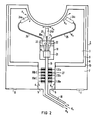
- FIG. 1 shows a magnetometer device in a patient couch.
- Figure 2 shows a Dewar vessel of this device.
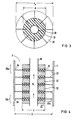
- FIGS. 3 and 4 illustrate a throttle device in this Dewar vessel in different views. Corresponding parts are provided with the same reference numerals in the figures.
- SQUID magnetometers as can be provided for single-channel or multi-channel devices according to the invention, are known in principle. They contain at least one superconducting gradiometer for detecting the magnetic signals (magnetic fluxes or flux gradients) emanating from a field source, in particular from the heart or brain of a patient. The detected signals are then over superconducting or normally conducting connecting conductors to a number of SQUIDs corresponding to the number of channels. Electronics are connected downstream of these SQUIDs, which can also be combined into an array. These known parts are not detailed in the figures.
- a double-walled Dewar vessel 2 which accommodates the superconducting magnetometers, is provided with an at least largely rotationally symmetrical design.
- the interior 3 of this vessel allows access via a relatively narrow neck 4. It is also provided in the neck area with at least one safety valve 5, through which cold gas can escape to the outside in the event of a fault.
- the space 7 between the walls 8 and 9 of the vessel 2 is evacuated in a known manner and optionally contains superinsulation, not shown in the figure.
- a thermal radiation shield 10 can be arranged in it.
- At least one safety valve 11 is also provided in the neck area for the vacuum space 7.
- the Dewar vessel 2 is advantageously arranged such that its neck 4 is geodetically lower than its interior 3 in an at least largely rotationally symmetrical configuration. According to the exemplary embodiment shown, the neck 4 is inclined downwards. This type of arrangement enables the vessel 2 to be integrated into a patient couch 14 standing on a floor 13. According to the illustrated embodiment, the Dewar 2 is tilted so that a comfortable lying position of a patient P results. The magnetic brain field of this patient is to be examined, for example. For this reason, the shape of the Dewar is adapted to the shape of the patient's head.
- the substructure of the patient couch 14 advantageously becomes a passive and / or additionally active sub with a full cross section pressure ventilation of the Dewar area used.
- the corresponding flow conditions of an active passage ventilation are indicated in the figure by arrowed lines 15.
- a suction gap 16 can be provided around the Dewar vessel 2 in the patient couch 14.
- the arrangement of the Dewar vessel 2 under the patient P also has the advantage that large masses for limiting vibration amplitudes, which could indirectly lead to magnetic disturbances, are to be attached below the patient.
- the dewar 2 is illustrated in more detail as a longitudinal section.
- an insert container 18 is introduced, which takes up the amount of a liquid refrigerant K 1, for example 2 to 3 l of liquid helium, required for a working period, for example a working day.
- This refrigerant is intended to cool the superconducting parts of the device according to the invention directly or indirectly.
- the refrigerant is refilled from below via a pipeline 19 leading through the neck 4, which represents a vacuum-insulated connection, which is cooled in countercurrent with exhaust gas from the refrigerant, to an external storage vessel, not shown.
- the refill can be repeated, for example on a daily basis.
- the particularly temperature-sensitive parts, in particular the SQUIDs are arranged in or on the insert container 18.
- SQUIDs are combined, for example, to form an array which is located on a chip 21, which is only indicated.
- the SQUIDs are connected to the corresponding gradiometers via, for example, superconducting conductors 22. Of these gradiometers, only three are indicated in the figure and designated 24a to 24c. Your number can, however, be significantly higher.
- the electrically conductive connecting conductors 22 are arranged inside hose-like refrigerant lines 25, which consist, for example, of a plastic. Electrical connecting conductors 22 can also be provided, which are integrated in the respectively assigned hose-like refrigerant lines.
- known film-like conductors can be covered with a hose-like sheath on at least one of their flat sides of the film, for example glued, so that the conductors are then to be regarded as part of a hose-like refrigerant line 25.
- relatively cold gaseous refrigerant K2 is supplied to the gradiometers 24a to 24c.
- the insert container 18 is provided with a lid 18a which is designed as a gas distributor and to which the refrigerant lines 25 are connected. If necessary, the exhaust gas rate is adjusted by a corresponding supply of heat into the insert container 18, for example by means of a heat-conducting rod made of glass fiber reinforced material.
- the cold gas enters the interior 3 at the gradiometers. It then leaves this interior on the neck 4. Particular care must be taken to prevent a backflow of warmer exhaust gas into the interior 3 due to convection based on temperature and density differences.
- a throttle device 27 is arranged in the neck 4, which only leaves or releases a relatively narrow gap for the exhaust gas K 3.
- the at least one gap causes the exhaust gas K3 which is under pressure in the interior to only come out.
- This exhaust gas can then optionally also be used for cooling further parts of the device, such as the radiation shield 10.
- the interior 3 can optionally also be provided with a glass ball filling.
- FIGS Figures 3 and 4 An embodiment of the throttle device 27 is shown in FIGS Figures 3 and 4 schematically illustrated as a cross section or longitudinal section. It is circular-cylindrical, wherein it surrounds the pipe 19 for the liquid refrigerant K1. For example, the device is pushed onto the pipeline.
- This device 27 contains a stack of several, for example five circular cylindrical elements 30a to 30e. Each of these throttle elements has a central annular disk-shaped clamping bracket 31, which consists for example of a glass fiber reinforced plastic.
- the outer diameter d of the holder is chosen to be significantly smaller than the inner diameter D of the tubular neck of the Dewar vessel.
- These plugs which can consist of a hard foam, for example, serve in particular to space the individual brackets 31 from one another.
- An annular disk-shaped plastic plate 33 is carried by each of these holders, which can consist in particular of a special polyester film.
- These relatively thin plates 33 have an outer diameter d a , which is only slightly smaller than the inner diameter D of the neck 4. It remains between the inner wall of the neck 4 and the disc-shaped plastic plate 33, a small gap 34 through which the exhaust gas K3 exits from the interior 3 of the Dewar vessel to the outside.
- annular disc-shaped, over the outer edge of the bracket 31 laterally projecting outer edge part 33a of each thin plate 33 is relatively flexible, so that this part can bend with a greater overpressure in the interior 3, for example in the event of a fault, and thus advantageously to a correspondingly larger flow cross section leads in columns 34 for the exhaust gas K3. If necessary, it is even possible that the elastic outer edge parts 33a of the plates 33 protrude up to the inner wall of the neck 4 and that the gaps 34 only due to bending of the parts 33a caused by the pressurized exhaust gas K3.
- the lid 18a of the insert container 18 is advantageously designed as a gas distributor and installed together with the gradiometers before the insert container is inserted.
- a galvanic multiple plug cf. EP-A-0 200 958 mentioned
- a planer multiple coupling transformer can advantageously be implemented, the coupling taking place automatically when the insert container is inserted.
- the insert container 18 and that around it giving Dewar 2 have the same axis. If the insert container is rotated by a predetermined angle relative to the Dewar axis, the standard position of the Dewar axis is freely definable. Then, for example, a horizontal Dewar axis is possible, which allows a patient easy access to the apex region if the patient rests normally on a patient couch. However, it must always be ensured that the insert container is arranged in such a way that only the gaseous refrigerant K 2 located above the liquid refrigerant K 1 reaches its cover.
- the neck 4 can be inclined (obliquely) downwards to horizontally, in particular with a rotationally symmetrical structure.
- the neck inclination does not play a special role; however, the position of the phase boundary in the insert container must be given.
- a rotationally symmetrical structure with, for example, a neck pointing obliquely downward (cf. FIG. 1) is advantageous.
Landscapes
- Physics & Mathematics (AREA)
- Engineering & Computer Science (AREA)
- Life Sciences & Earth Sciences (AREA)
- Health & Medical Sciences (AREA)
- Pathology (AREA)
- Medical Informatics (AREA)
- General Engineering & Computer Science (AREA)
- Thermal Sciences (AREA)
- General Physics & Mathematics (AREA)
- Biophysics (AREA)
- Condensed Matter Physics & Semiconductors (AREA)
- Biomedical Technology (AREA)
- Heart & Thoracic Surgery (AREA)
- Mechanical Engineering (AREA)
- Molecular Biology (AREA)
- Surgery (AREA)
- Animal Behavior & Ethology (AREA)
- General Health & Medical Sciences (AREA)
- Public Health (AREA)
- Veterinary Medicine (AREA)
- Measurement And Recording Of Electrical Phenomena And Electrical Characteristics Of The Living Body (AREA)
- Measuring Magnetic Variables (AREA)
- Measuring And Recording Apparatus For Diagnosis (AREA)
Abstract
Description
Die Erfindung bezieht sich auf eine Magnetometer-Einrichtung zur Messung schwacher, von mindestens einer zu detektierenden Feldquelle hervorgerufener Magnetfeld mit einem Dewar-Gefäß, das einen Innenraum mit einem Zugang über einen Hals aufweist und in dessen Innenraum mehrere supraleitende Gradiometer sowie ihnen zugeordnete SQUIDs angeordnet sind, die von einem von außen über den Hals zugeführten Kältemittel gekühlt sind. Eine derartige Magnetometer-Einrichtung ist z.B. in der Veröffentlichung "Physics Today", März 1986, Seiten 36 bis 44 angedeutet.The invention relates to a magnetometer device for measuring weak magnetic field caused by at least one field source to be detected with a dewar vessel, which has an interior with an access via a neck and in the interior of which a number of superconducting gradiometers and SQUIDs assigned to them are arranged which are cooled by a refrigerant supplied from the outside via the neck. Such a magnetometer device is e.g. in the publication "Physics Today", March 1986, pages 36 to 44.
Zur Messung sehr schwacher Magnetfelder ist eine Verwendung von supraleitenden Quanten-Interferometern, sogenannten "SQUIDs" (Abkürzung von: "Superconducting QUantum Interference Devices"), allgemein bekannt (vgl. z.B. "J.Phys.E.: Sci.Instrum.", Vol. 13, 1980, Seiten 801 bis 813 oder "IEEE Trans. Electron Dev.", Vol. ED-27, No. 10, Oktober 1980, Seiten 1896 bis 1908). Als ein bevorzugtes Anwendungsgebiet für diese Interferometer wird auf dem Gebiet der medizinischen Diagnostik die Magnetokardiographie oder Magnetoenzephalographie angesehen. Die hierbei hervorgerufenen Magnetfelder von magnetischen Herz- bzw. Gehirnwellen haben nämlich Feldstärken in der Größenordnung von nur etwa 50 pT bzw. 0,1 pT (vgl. z.B. "Biomagnetism - Proceedings Third international Workshop on Biomagnetism, Berlin 1980", Berlin/New York 1981, Seiten 3 bis 31). Diese sehr schwachen Felder müssen zudem noch bei Anwesenheit von verhältnismäßig großen Störfeldern zu detektieren sein.The use of superconducting quantum interferometers, so-called “SQUIDs” (abbreviation of: “ S uperconducting QU antum I nterference D evices”), is generally known for measuring very weak magnetic fields (cf., for example, “J.Phys.E .: Sci. Instrum. ", Vol. 13, 1980, pages 801 to 813 or" IEEE Trans. Electron Dev. ", Vol. ED-27, No. 10, October 1980, pages 1896 to 1908). Magnetocardiography or magnetoencephalography is regarded as a preferred field of application for these interferometers in the field of medical diagnostics. The magnetic fields caused by magnetic heart or brain waves have field strengths of the order of magnitude of only about 50 pT or 0.1 pT (see, for example, "Biomagnetism - Proceedings Third international Workshop on Biomagnetism, Berlin 1980", Berlin / New York 1981,
Zur Messung derartiger biomagnetischer Felder in der genannten Größenordnung sind Meßeinrichtungen bekannt, die ein- oder insbesondere auch mehrkanalig ausgeführt sein können (vgl. z.B. DE-OS 32 47 543). Diese Einrichtungen enthalten je nach Anzahl der Kanäle SQUID-Magnetometer mit Gradiometern 1. oder höherer Ordnung.For the measurement of such biomagnetic fields in the order of magnitude mentioned, measuring devices are known which can be designed in one or in particular also in multiple channels (cf. e.g. DE-OS 32 47 543). Depending on the number of channels, these devices contain SQUID magnetometers with first or higher order gradiometers.
Eine entsprechende Magnetometer-Einrichtung ist aus der eingangs genannten Literaturstelle "Physics Today" ersichtlich. Die supraleitenden Gradiometer sind zusammen mit den ihnen zugeordneten SQUIDs innerhalb eines Dewar-Gefäßes angeordnet. Hierbei ist eine Kühlung der supraleitenden Einbauten, insbesondere der hochempfindlichen SQUIDs, unter Vermeidung von direkten und indirekten magnetischen Störungen erforderlich. Man verzichtet deshalb auf eine Kühltechnik unter Einsatz von Kältemaschinen, die mit ihrer elektromagnetischen Abstrahlung und mit ihren bewegten magnetischen Teilen über Vibrationen magnetische Störfelder erzeugen. Gekühlt wird folglich mit einem Vorrat an Kältemittel, insbesondere flüssigem Helium, der in Zeitabständen von mehreren Tagen zu ergänzen ist.A corresponding magnetometer device can be seen from the "Physics Today" reference mentioned at the beginning. The superconducting gradiometers, together with the SQUIDs assigned to them, are arranged within a Dewar vessel. In this case, cooling of the superconducting internals, in particular the highly sensitive SQUIDs, is necessary while avoiding direct and indirect magnetic interference. There is therefore no cooling technology using chillers that generate electromagnetic interference fields with their electromagnetic radiation and with their moving magnetic parts via vibrations. Cooling is consequently carried out with a supply of refrigerant, in particular liquid helium, which must be supplemented at intervals of several days.
Bei der bekannten Magnetometer-Einrichtung sind jedoch die die supraleitenden Gradiometer und SQUIDs aufnehmenden Dewar-Gefäße oberhalb der zu detektierenden Feldquelle eines zu untersuchenden Patienten angeordnet. Geht man von Füllmengen von etwa 15 bis 30 l an flüssigem Kältemittel pro Dewar aus, wie sie z.B. für mehrkanalige Einrichtungen üblich sind, so führt die gewählte Anordnung der Dewar-Gefäße zu einer Gefährdung des direkt darunterliegenden Patienten. Im Fall eines plötzlichen Zusammenbruchs des Isoliervakuums bzw. einer plötzlichen Beschädigung eines Dewar-Gefäßes mit Ansprechen von Sicherheitsventilen würde sich nämlich eine nicht unbedenkliche Kaltgasmenge über den Patienten ergießen. So erzeugen z.B. die erheblichen Helium-Füllmengen von 15 bis 30 l Flüssigkeit in einem entsprechenden Notfall etwas 10 bis 30 m³ Helium-Kaltgas. Dieses Kaltgas ist schwerlich vom Patienten fernzuhalten, insbesondere dann, wenn die Untersuchung in einer Abschirmkabine durchgeführt wird. Eine Überkopf-Anordnung von Dewar-Gefäßen kann außerdem von Patienten als unangenehm empfunden werden.In the known magnetometer device, however, the Dewar vessels which hold the superconducting gradiometers and SQUIDs are arranged above the field source to be detected of a patient to be examined. If one assumes filling quantities of approximately 15 to 30 l of liquid refrigerant per dewar, as are customary, for example, for multi-channel devices, the chosen arrangement of the dewar vessels puts the patient directly below at risk. In the event of a sudden breakdown of the insulating vacuum or a sudden damage to a Dewar vessel with the response of safety valves, an amount of cold gas which is not harmless would pour out over the patient. For example, the considerable helium fill quantities of 15 to 30 l of liquid in a corresponding emergency about 10 to 30 m³ cold helium gas. This cold gas is difficult to keep away from the patient, especially if the examination is carried out in a shielding cabin. An overhead arrangement of Dewar vessels can also be uncomfortable for patients.
Aufgabe der vorliegenden Erfindung ist es deshalb, die Magnetometer-Einrichtung der eingangs genannten Art dahingehend auszugestalten, daß die Anordnung mindestens eines Dewar-Gefäßes zu keiner Gefährdung eines Patienten führen kann und daß dennoch ein Einsatz von magnetische Störungen hervorrufenden Kältemaschinen nicht erforderlich wird.The object of the present invention is therefore to design the magnetometer device of the type mentioned at the outset such that the arrangement of at least one Dewar vessel can not endanger a patient and that the use of chillers which cause magnetic interference is not necessary.
Diese Aufgabe wird erfindungsgemäß dadurch gelöst,
- daß das Dewar-Gefäß unterhalb oder seitlich von der mindestens einen Feldquelle angeordnet ist,
- daß in dem Innenraum ein besonderer Einsatzbehälter vorgesehen ist, in den über eine durch den Hals führende Rohrleitung flüssiges Kältemittel einzuspeisen ist,
- daß sich in oder an dem Einsatzbehälter die SQUIDs befinden,
- daß dem Einsatzbehälter entnommenes gasförmiges Kältemittel über mindestens eine rohrförmige Verbindungsleitung den supraleitenden Gradiometern zuzuführen ist,
- daß das an den Gradiometern in den Innenraum entweichende gasförmige Kältemittel über den Hals nach außen abzuführen ist
und
- daß in den Hals eine einen Rückstrom von wärmerem gasförmigen Kühlmittel in den Innenraum unterbindende Drosselvorrichtung eingesetzt ist.According to the invention, this object is achieved by
that the Dewar vessel is arranged below or to the side of the at least one field source,
that a special insert container is provided in the interior, into which liquid refrigerant is to be fed via a pipeline leading through the neck,
- that the SQUIDs are located in or on the insert container,
that gaseous refrigerant removed from the insert container is to be supplied to the superconducting gradiometers via at least one tubular connecting line,
- That the gaseous refrigerant escaping from the gradiometers into the interior is to be discharged through the neck to the outside
and
- That in the neck a backflow of warmer gaseous coolant in the interior suppressing throttle device is used.
Die mit dieser Ausgestaltung der Erfindung verbundenen Vor teile sind insbesondere darin zu sehen, daß eine Überkopf-Anordnung des Dewar-Gefäßes vermieden wird und dennoch eine effektive Kühlung der supraleitenden Teile der Einrichtung zu gewährleisten ist. Hierbei werden unerwünschte Konvektionen von Abgas des Kältemittels unterbunden. So sorgen z.B. die rohrförmigen Verbindungsleitungen für eine ungestörte Zufuhr von besonders kaltem Abgas zu den supraleitenden Gradiometern, obwohl diese Gradiometer im allgemeinen geodätisch höher als der Einsatzbehälter und somit entgegengesetzt zu der Richtung angeordnet sind, in der das Kältemittel aufgrund einer durch Temperatur- und Dichteunterschiede angefachten Konvektion zu strömen versucht. Die im Bereich des Halses angeordnete Drosselvorrichtung verhindert außerdem, daß wärmeres Abgas von außen in den Innenraum zurückfließen kann.The associated with this embodiment of the invention parts can be seen in particular in that an overhead arrangement of the Dewar vessel is avoided and yet effective cooling of the superconducting parts of the device must be ensured. Unwanted convection of exhaust gas from the refrigerant is prevented. For example, the tubular connecting lines ensure an undisturbed supply of particularly cold exhaust gas to the superconducting gradiometers, although these gradiometers are generally geodetically higher than the insert container and thus arranged opposite to the direction in which the refrigerant is fanned due to temperature and density differences Tried to flow convection. The throttle device arranged in the region of the neck also prevents warmer exhaust gas from flowing back into the interior from the outside.
Vorteilhafte Ausgestaltungen der Magnetometer-Einrichtung nach der Erfindung gehen aus den Unteransprüchen hervor.Advantageous refinements of the magnetometer device according to the invention emerge from the subclaims.
Zur weiteren Erläuterung der Erfindung wird nachfolgend auf die schematische Zeichnung Bezug genommen, in deren Figur 1 eine Magnetometer-Einrichtung in einer Patientenliege angedeutet ist. Figur 2 zeigt ein Dewar-Gefäß dieser Einrichtung. In den Figuren 3 und 4 ist eine Drosselvorrichtung in diesem Dewar-Gefäß in verschiedener Ansicht veranschaulicht. Dabei sind in den Figuren sich entsprechende Teile mit denselben Bezugszeichen versehen.To further explain the invention, reference is made below to the schematic drawing, in which FIG. 1 shows a magnetometer device in a patient couch. Figure 2 shows a Dewar vessel of this device. FIGS. 3 and 4 illustrate a throttle device in this Dewar vessel in different views. Corresponding parts are provided with the same reference numerals in the figures.
SQUID-Magnetometer, wie sie für ein- oder insbesondere mehrkanalige Einrichtungen nach der Erfindung vorgesehen werden können, sind prinzipiell bekannt. Sie enthalten zur Detektion der von einer Feldquelle, insbesondere vom Herz oder vom Gehirn eines Patienten ausgehenden magnetischen Signale (magnetische Flüsse oder Flußgradienten) mindestens ein supraleitendes Gradiometer. Die detektierten Signale werden dann über supraleitende oder normalleitende Verbindungsleiter einer der Kanalzahl entsprechenden Anzahl von SQUIDs zugeführt. Diesen SQUIDs, die ebenfalls zu einem Array zusammengefaßt sein können, ist eine Elektronik nachgeschaltet. In den Figuren sind diese bekannten Teile nicht näher ausgeführt.SQUID magnetometers, as can be provided for single-channel or multi-channel devices according to the invention, are known in principle. They contain at least one superconducting gradiometer for detecting the magnetic signals (magnetic fluxes or flux gradients) emanating from a field source, in particular from the heart or brain of a patient. The detected signals are then over superconducting or normally conducting connecting conductors to a number of SQUIDs corresponding to the number of channels. Electronics are connected downstream of these SQUIDs, which can also be combined into an array. These known parts are not detailed in the figures.
Gemäß dem in Figur 1 gezeigten Längsschnitt ist ein die supraleitenden Magnetometer aufnehmendes doppelwandiges Dewar-Gefäß 2 mit zumindest weitgehend rotationssymmetrischem Aufbau vorgesehen. Der Innenraum 3 dieses Gefäßes erlaubt einen Zugang über einen verhältnismäßig engen Hals 4. Er ist außerdem im Halsbereich mit mindestens einem Sicherheitsventil 5 versehen, über das in einem Störungsfall Kaltgas nach außen entweichen kann. Der Zwischenraum 7 zwischen den Wänden 8 und 9 des Gefäßes 2 ist in bekannter Weise evakuiert und enthält gegebenenfalls eine in der Figur nicht dargestellte Superisolation. Außerdem kann in ihm ein thermischer Strahlungsschild 10 angeordnet sein. Für den Vakuumraum 7 ist im Halsbereich ebenfalls mindestens ein Sicherheitsventil 11 vorgesehen.According to the longitudinal section shown in FIG. 1, a double-walled Dewar
Das Dewar-Gefäß 2 ist vorteilhaft so angeordnet, daß bei zumindest weitgehend rotationssymmetrischer Ausgestaltung sein Hals 4 geodätisch tiefer liegt als sein Innenraum 3. Gemäß dem dargestellten Ausführungsbeispiel ist der Hals 4 schräg nach unten geneigt. Diese Anordnungsart ermöglicht es, daß das Gefäß 2 in eine auf einem Boden 13 stehende Patientenliege 14 integriert werden kann. Gemäß dem dargestellten Ausführungsbeispiel ist das Dewar-Gefäß 2 dabei so verkippt, daß sich eine bequeme Liegeposition eines Patienten P ergibt. Von diesem Patienten soll beispielsweise das magnetische Gehirnfeld untersucht werden. Aus diesem Grunde ist die Form des Dewar-Gefäßes der Kopfform des Patienten entsprechend angepaßt.The Dewar
Der Unterbau der Patientenliege 14 wird vorteilhaft auf vollem Querschnitt zur passiven und/oder zuzüglich aktiven Unter druck-Lüftung des Dewar-Bereiches genutzt. Die entsprechenden Strömungsverhältnisse einer aktiven Durchgangs-Lüftung sind in der Figur durch gepfeilte Linien 15 angedeutet. Zusätzlich kann in der Patientenliege 14 ein Absaugspalt 16 um das Dewar-Gefäß 2 herum vorgesehen werden. Beim Ansprechen der Sicherheitsventile 5 oder 11 vom Innenraum 3 bzw. vom Vakuumraum 7 entweicht dann das entsprechende Kaltgas in den Unterbau der Patientenliege und wird dort auf großem Querschnitt abgesaugt.The substructure of the
Die Anordnung des Dewar-Gefäßes 2 unter dem Patienten P hat außerdem den Vorteil, daß große Massen zur Begrenzung von Vibrationsamplituden, die indirekt zu magnetischen Störungen führen könnten, unterhalb des Patienten anzubringen sind.The arrangement of the Dewar
In Figur 2 ist das Dewar-Gefäß 2 als Längsschnitt näher veranschaulicht. In seinen Innenraum 3 ist ein Einsatzbehälter 18 eingebracht, der die für eine Arbeitsperiode, beispielsweise einen Arbeitstag, erforderliche Menge eines flüssigen Kältemittels K₁, z.B. 2 bis 3 l flüssiges Helium, aufnimmt. Dieses Kältemittel soll zur Kühlung der supraleitenden Teile der erfindungsgemäßen Einrichtung unmittelbar oder mittelbar dienen. Nachgefüllt wird das Kältemittel von unten über eine durch den Hals 4 führende Rohrleitung 19, welche eine vakuumisolierte und im Gegenstrom mit Abgas des Kältemittels gekühlte Verbindung zu einem externen, nicht dargestellten Vorratsgefäß darstellt. Die Nachfüllung kann dabei repetierend, z.B. im Tagesrhythmus erfolgen. Im bzw. an dem Einsatzbehälter 18 sind die besonders temperaturempfindlichen Teile, insbesondere die SQUIDs angeordnet. Diese in der Figur nicht dargestellten SQUIDs sind beispielsweise zu einem Array zusammengefaßt, das sich auf einem nur angedeuteten Chip 21 befindet. Die SQUIDs sind über beispielsweise supraleitende Leiter 22 mit den entsprechenden Gradiometern verbunden. Von diesen Gradiometern sind in der Figur nur drei angedeutet und mit 24a bis 24c bezeichnet. Ihre Anzahl kann jedoch wesentlich darüber liegen. Die elektrisch leitenden Verbindungsleiter 22 sind innerhalb von schlauchartigen Kältemittelleitungen 25 angeordnet, die beispielsweise aus einem Kunststoff bestehen. Es können auch elektrische Verbindungsleiter 22 vorgesehen werden, die in die jeweils zugeordneten schlauchartigen Kältemittelleitungen integriert sind. So lassen sich z.B. bekannte folienartige Leiter auf mindestens einer ihrer Flachseiten der Folie mit einer schlauchartigen Hülle überziehen, beispielsweise bekleben, so daß dann die Leiter als Teil einer schlauchartigen Kältemittelleitung 25 anzusehen sind. Über die Leitungen 25 wird in dem Einsatzbehälter 18 entstehendes, verhaltnismaßig kaltes gasförmiges Kältemittel K₂ den Gradiometern 24a bis 24c zugeführt. Der Einatzbehälter 18 ist hierzu mit einem Deckel 18a versehen, der als Gasverteiler ausgebildet ist und an den die Kältemittelleitungen 25 angeschlossen sind. Bei Bedarf wird die Abgasrate durch eine entsprechende Wärmezufuhr in den Einsatzbehälter 18, z.B. mittels eines wärmeleitenden Stabes aus glasfaserverstärktem Material, eingestellt. An den Gradiometern tritt das Kaltgas in den Innenraum 3 ein. Es verläßt dann diesen Innenraum an dem Hals 4. Dabei ist besondere Sorgfalt aufzuwenden, um einen Rückstrom von wärmerem Abgas in den Innenraum 3 aufgrund einer auf Temperatur- und Dichteunterschieden basierenden Konvektion zu verhindern. Zu diesem Zweck ist in dem Hals 4 eine Drosselvorrichtung 27 angeordnet, die nur einen verhältnismäßig engen Spalt für das Abgas K₃ freiläßt oder freigibt. Der mindestens eine Spalt bewirkt dabei, daß das in dem Innenraum unter Überdruck stehende Abgas K₃ nur nach außen tritt. Dieses Abgas kann gegebenenfalls dann noch zur Abkühlung von weiteren Teilen der Einrichtung wie z.B. des Strahlungsschildes 10 herangezogen werden. Zur weiteren Begrenzung einer möglichen Kaltgaskonvektion kann außerdem der Innenraum 3 gegebenenfalls noch mit einer Glaskugelfüllung versehen werden.In Figure 2, the
Eine Ausführungsform der Drosselvorrichtung 27 ist in den Figuren 3 und 4 als Querschnitt bzw. Längsschnitt schematisch veranschaulicht. Sie ist kreisringzylindrisch ausgebildet, wobei sie die Rohrleitung 19 für das flüssige Kältemittel K₁ umschließt. Beispielsweise ist die Vorrichtung auf die Rohrleitung aufgeschoben. Diese Vorrichtung 27 enthält einen Stapel aus mehreren, beispielsweise fünf kreiszylindrischen Elementen 30a bis 30e. Jedes dieser Drosselelemente weist dabei eine zentrale ringscheibenförmige Klemmhalterung 31 auf, die beispielsweise aus einem glasfaserverstärkten Kunststoff besteht. Der Außendurchmesser d der Halterung ist dabei deutlich geringer als der Innendurchmesser D des rohrförmigen Halses des Dewar-Gefäßes gewählt. Auf den gegenüberliegenden Flachseiten der einzelnen Halterungen befinden sich kreisringzylindrische Stopfen 32 mit entsprechendem Durchmesser d. Diese Stopfen, die beispielsweise aus einem Hartschaum bestehen können, dienen insbesondere zur Beabstandung der einzelnen Halterungen 31 untereinander. Von jeder dieser Halterungen wird ein ringscheibenförmiges Kunststoffplättchen 33 getragen, das insbesondere aus einer speziellen Polyesterfolie bestehen kann. Diese verhältnismäßig dünnen Plättchen 33 haben einen Außendurchmesser da, der nur geringfugig kleiner als der Innendurchmesser D des Halses 4 ist. Es verbleibt so zwischen der Innenwand des Halses 4 und den scheibenförmigen Kunststoffplättchen 33 jeweils ein geringer Spalt 34, durch den das Abgas K₃ aus dem Innenraum 3 des Dewar-Gefäßes nach außen tritt. Der ringscheibenförmige, über den Außenrand der Halterung 31 seitlich hinausragende Außenrandteil 33a jedes dünnen Plättchens 33 ist verhältnismäßig flexibel, so daß sich dieser Teil bei einem stärkeren Überdruck in dem Innenraum 3, beispielsweise in einem Störungsfall, verbiegen kann und so vorteilhaft zu einem entsprechend größeren Strömungsquerschnitt in den Spalten 34 für das Abgas K₃ führt. Gegebenenfalls ist es sogar möglich, daß die elastischen Außenrandteile 33a der Plättchen 33 bis an die Innenwand des Halses 4 heranragen und daß die Spalte 34 erst aufgrund eines Verbiegens der Teile 33a durch das unter Überdruck stehende Abgas K₃ hervorgerufen werden.An embodiment of the
Gemäß dem in den Figuren dargestellten Ausführungsbeispiel wurde davon ausgegangen, daß das Dewar-Gefäß 2 eine bauchige Erweiterung seines Innenraumes 3 gegenüber dem Halsbereich aufweist (vgl. z.B. EP-A-0 200 958). In diesem Fall kann mit Halteelementen, die sich nach Einführung in den Innenraum aufspreizen, und/oder mit einer Steckverbindung zwischen dem Einsatzbehälter 18 und den vorher eingebauten Gradiometern 24a bis 24c gearbeitet werden. Selbstverständlich können auch Dewar-Gefäße ohne bauchige Erweiterungen vorgesehen sein, die keine besonderen Probleme beim Einbau der, vorgesehenen Systeme bereiten. Bei beiden Gefäßformen sind die folgenden zwei Fälle zu unterscheiden:
- 1) Die SQUIDs sind mit den zugeordneten Gradiometern zu Modulen integriert. Hierbei müssen lediglich normalleitende Anschlüsse und die Abgaskühlverbindungen hergestellt werden.
- 2) Gemäß dem angenommenen Ausführungsbeispiel sind die SQUIDs im oder am Einsatzbehälter zusammengefaßt. Dann sind supraleitende Verbindungen zu den Gradiometern sowie die Abgaskühlungen der Gradiometer herzustellen.
- 1) The SQUIDs are integrated with the assigned gradiometers into modules. All that is required here is to make normal-conducting connections and the exhaust gas cooling connections.
- 2) According to the assumed exemplary embodiment, the SQUIDs are combined in or on the insert container. Then superconducting connections to the gradiometers as well as the exhaust gas cooling of the gradiometers have to be established.
In beiden Fällen wird der Deckel 18a des Einsatzbehälters 18 vorteilhaft als Gasverteiler ausgebildet und zusammen mit den Gradiometern vor Einbringen des Einsatzbehälters eingebaut. Im ersteren Fall wird vorteilhaft ein galvanischer Vielfachstecker (vgl. die genannte EP-A-0 200 958) vorgesehen. Demgegenüber ist im zweiten Fall vorteilhaft ein planerer Vielfach-Koppeltransformator zu realisieren, wobei die Verkopplung beim Einfügen des Einsatzbehälters von selbst erfolgt.In both cases, the
Ferner ist es für die erfindungsgemäße Einrichtung nicht unbedingt erforderlich, daß der Einsatzbehälter 18 und das ihn um gebende Dewar-Gefäß 2 dieselbe Achse aufweisen. Wird der Einsatzbehälter um einen vorgegebenen Winkel relativ zu der Dewar-Achse gedreht, so ergibt sich eine frei vorzugebende Standardlage der Dewar-Achse. Dann ist z.B. eine horizontalliegende Dewar-Achse möglich, die für einen Patienten bequemen Zugang zu dessen Scheitelregion ermöglicht, falls der Patient normal auf einer Patientenliege ruht. Hierbei muß jedoch stets gewährleistet bleiben, daß der Einsatzbehälter so angeordnet ist, daß an seinen Deckel lediglich das über dem flüssigen Kältemittel K₁ befindliche gasförmige Kältemittel K₂ gelangt. Bei der erfindungsgemäßen Einrichtung kann also bei insbesondere rotationssymmetrischem Aufbau der Hals 4 (schräg) nach unten bis horizontal geneigt sein. Prinzipiell spielt die Halsneigung keine besondere Rolle; jedoch muß die erwähnte Lage der Phasengrenze in dem Einsatzbehälter gegeben sein. Aus Gründen einer einfachen Montage und Halterung ist aber ein rotationssymmetrischer Aufbau mit beispielsweise schräg nach unten weisendem Hals (vgl. Fig. 1) von Vorteil.Furthermore, it is not absolutely necessary for the device according to the invention that the
Claims (15)
-daß das Dewar-Gefäß (2) unterhalb oder seitlich von der mindestens einen Feldquelle angeordnet ist,
-daß in dem Innenraum (3) ein besonderer Einsatzbehälter (18) vorgesehen ist, in den über eine durch den Hals (4) führende Rohrleitung (19) flüssiges Kältemittel (K₁) einzuspeisen ist,
- daß sich in oder an dem Einsatzbehälter (18) die SQUIDs (Chip 21) befinden,
-daß dem Einsatzbehälter (18) entnommenes gasförmiges Kältemittel (K₂) über mindestens eine schlauchartige Leitung (25) den supraleitenden Gradiometern (24a-24c) zuzuführen ist,
- daß das an den Gradiometern (24a-24c) in den Innenraum (3) entweichende gasförmige Kältemittel (K₃) über den Hals (4) nach außen abzuführen ist
und
- daß in den Hals (4) eine einen Rückstrom von wärmerem gasförmigen Kühlmittel in den Innenraum (3) unterbindende Drosselvorrichtung (27) eingesetzt ist.1.Magnetometer device for measuring weak magnetic fields caused by at least one field source to be detected with a Dewar vessel, which has an interior with an access via a neck and in the interior of which a number of superconducting gradiometers and SQUIDs assigned to them are arranged, which are arranged by a refrigerants supplied from outside via the neck are cooled, characterized in that
that the Dewar vessel (2) is arranged below or to the side of the at least one field source,
-that a special insert container (18) is provided in the interior (3) into which liquid refrigerant (K₁) is to be fed via a pipe (19) leading through the neck (4),
- That the SQUIDs (chip 21) are located in or on the insert container (18),
-that gaseous refrigerant (K₂) removed from the insert container (18) is to be fed to the superconducting gradiometers (24a-24c) via at least one hose-like line (25),
- That on the gradiometers (24a-24c) in the interior (3) escaping gaseous refrigerant (K₃) via the neck (4) is to be discharged to the outside
and
- That in the neck (4) a backflow of warmer gaseous coolant into the interior (3) suppressing throttle device (27) is used.
Applications Claiming Priority (2)
| Application Number | Priority Date | Filing Date | Title |
|---|---|---|---|
| DE3831545 | 1988-09-16 | ||
| DE3831545 | 1988-09-16 |
Publications (1)
| Publication Number | Publication Date |
|---|---|
| EP0361137A1 true EP0361137A1 (en) | 1990-04-04 |
Family
ID=6363105
Family Applications (1)
| Application Number | Title | Priority Date | Filing Date |
|---|---|---|---|
| EP89116322A Withdrawn EP0361137A1 (en) | 1988-09-16 | 1989-09-04 | Magnetometer device with a cryostat for the measurement of weak magnetic fields |
Country Status (3)
| Country | Link |
|---|---|
| US (1) | US4996479A (en) |
| EP (1) | EP0361137A1 (en) |
| JP (1) | JPH02114941A (en) |
Cited By (11)
| Publication number | Priority date | Publication date | Assignee | Title |
|---|---|---|---|---|
| EP0463481A1 (en) * | 1990-06-25 | 1992-01-02 | Siemens Aktiengesellschaft | Cooling arrangement for a squid measurement device |
| EP0492262A2 (en) * | 1990-12-21 | 1992-07-01 | Neuromag Ltd. | A multichannel device for measurement of weak spatially and temporally varying magnetic fields |
| EP0595227A1 (en) * | 1992-10-27 | 1994-05-04 | Biomagnetic Technologies, Inc. | Biomagnetometer having flexible sensor |
| WO1995000858A1 (en) * | 1993-06-21 | 1995-01-05 | Biomagnetic Technologies, Inc. | Biomagnetometer with solid conduction cooling |
| EP0884601A1 (en) * | 1997-06-11 | 1998-12-16 | Kanazawa Institute of Technology | Magnetometer |
| US5896645A (en) * | 1995-12-14 | 1999-04-27 | Kanazawa Institute Of Technology | Method of assembling a magnetomeasuring apparatus |
| US9132278B2 (en) | 2005-06-16 | 2015-09-15 | Brainsway, Ltd. | Transcranial magnetic stimulation system and methods |
| US9248308B2 (en) | 2013-02-21 | 2016-02-02 | Brainsway, Ltd. | Circular coils for deep transcranial magnetic stimulation |
| US9254394B2 (en) | 2013-02-21 | 2016-02-09 | Brainsway, Ltd. | Central base coils for deep transcranial magnetic stimulation |
| US9533168B2 (en) | 2013-02-21 | 2017-01-03 | Brainsway, Ltd. | Unilateral coils for deep transcranial magnetic stimulation |
| DE102022201697A1 (en) | 2022-02-18 | 2023-08-24 | Robert Bosch Gesellschaft mit beschränkter Haftung | Sensor unit and method for detecting brainwave induced magnetic fields |
Families Citing this family (26)
| Publication number | Priority date | Publication date | Assignee | Title |
|---|---|---|---|---|
| JPH0767440B2 (en) * | 1990-09-30 | 1995-07-26 | 工業技術院長 | Reference part detection method for magnetocardiogram synchronization detection, magnetocardiogram synchronization addition method, magnetocardiogram synchronization detection device and magnetocardiogram synchronization addition device |
| JP2772739B2 (en) * | 1991-06-20 | 1998-07-09 | いわき電子株式会社 | External electrode structure of leadless package and method of manufacturing the same |
| JPH0614899A (en) * | 1991-11-06 | 1994-01-25 | Mitsui Mining & Smelting Co Ltd | Cerebral magnetic field measuring instrument |
| US5274327A (en) * | 1992-06-12 | 1993-12-28 | Xerox Corporation | Powder sample holding capsule holding adapter for a vibrating sample magnetometer |
| JP3106701B2 (en) * | 1992-06-29 | 2000-11-06 | ダイキン工業株式会社 | Biomagnetic field measurement device |
| US5393736A (en) * | 1992-11-30 | 1995-02-28 | Illinois Superconductor Corporation | Cryogenic fluid level sensor |
| US5441107A (en) * | 1993-06-21 | 1995-08-15 | Biomagnetic Technologies, Inc. | Solid conductor thermal feedthrough |
| US5494033A (en) * | 1993-06-21 | 1996-02-27 | Biomagnetic Technologies, Inc. | Biomagnetometer with sealed vacuum enclosure and solid conduction cooling |
| US5713354A (en) * | 1994-08-01 | 1998-02-03 | Biomagnetic Technologies, Inc. | Biomagnetometer with whole head coverage of a seated reclined subject |
| WO1996039076A1 (en) * | 1995-06-05 | 1996-12-12 | Vanderbilt University | Non-invasive identification of intestinal ischemia from measurement of basic electrical rhythm of intestinal smooth muscle electrical activity |
| US6480111B2 (en) | 2000-01-10 | 2002-11-12 | Southwest Research Institute | Motion detection for physiological applications |
| US7130675B2 (en) * | 2002-06-28 | 2006-10-31 | Tristan Technologies, Inc. | High-resolution magnetoencephalography system and method |
| US7197352B2 (en) * | 2002-08-26 | 2007-03-27 | Tristan Technologies, Inc. | High-resolution magnetoencephalography system, components and method |
| WO2004017811A2 (en) * | 2002-08-26 | 2004-03-04 | Tristan Technologies, Inc. | High-resolution magnetoencephalography system and method |
| US20050149169A1 (en) * | 2003-04-08 | 2005-07-07 | Xingwu Wang | Implantable medical device |
| US20050149002A1 (en) * | 2003-04-08 | 2005-07-07 | Xingwu Wang | Markers for visualizing interventional medical devices |
| US8000767B2 (en) * | 2004-01-20 | 2011-08-16 | Board Of Trustees Of The University Of Illinois | Magneto-optical apparatus and method for the spatially-resolved detection of weak magnetic fields |
| JP4595102B2 (en) * | 2004-12-20 | 2010-12-08 | 独立行政法人情報通信研究機構 | Measuring structure of superconducting magnetic shield brain magnetic field measuring device |
| CN108778114B (en) | 2016-03-03 | 2022-03-01 | 株式会社理光 | Magnetic measuring device |
| US11723579B2 (en) | 2017-09-19 | 2023-08-15 | Neuroenhancement Lab, LLC | Method and apparatus for neuroenhancement |
| US11375934B2 (en) | 2017-12-01 | 2022-07-05 | Ricoh Company, Ltd. | Biomagnetic measurement apparatus, biological information measurement apparatus, and biomagnetic measurement method |
| US11717686B2 (en) | 2017-12-04 | 2023-08-08 | Neuroenhancement Lab, LLC | Method and apparatus for neuroenhancement to facilitate learning and performance |
| US11478603B2 (en) | 2017-12-31 | 2022-10-25 | Neuroenhancement Lab, LLC | Method and apparatus for neuroenhancement to enhance emotional response |
| US11364361B2 (en) | 2018-04-20 | 2022-06-21 | Neuroenhancement Lab, LLC | System and method for inducing sleep by transplanting mental states |
| US11452839B2 (en) | 2018-09-14 | 2022-09-27 | Neuroenhancement Lab, LLC | System and method of improving sleep |
| US11786694B2 (en) | 2019-05-24 | 2023-10-17 | NeuroLight, Inc. | Device, method, and app for facilitating sleep |
Citations (3)
| Publication number | Priority date | Publication date | Assignee | Title |
|---|---|---|---|---|
| EP0156240A2 (en) * | 1984-03-30 | 1985-10-02 | General Electric Company | Horizontal cryostat penetration insert and assembly |
| WO1985004489A1 (en) * | 1984-04-03 | 1985-10-10 | Geo-Sensors Corporation | Magnetic probe |
| EP0200958A1 (en) * | 1985-04-26 | 1986-12-17 | Siemens Aktiengesellschaft | Apparatus for measuring weak magnetic fields using several gradiometers |
Family Cites Families (5)
| Publication number | Priority date | Publication date | Assignee | Title |
|---|---|---|---|---|
| DE3247543A1 (en) * | 1982-12-22 | 1984-06-28 | Siemens AG, 1000 Berlin und 8000 München | DEVICE FOR MULTI-CHANNEL MEASUREMENT OF LOW, CHANGING MAGNETIC FIELDS AND METHOD FOR THEIR PRODUCTION |
| JPS6071972A (en) * | 1983-09-28 | 1985-04-23 | Shimadzu Corp | Automatic inserting device of probe of superconduction magnetometer |
| US4689559A (en) * | 1984-11-13 | 1987-08-25 | Sperry Corporation | Apparatus and method to reduce the thermal response of SQUID sensors |
| US4827217A (en) * | 1987-04-10 | 1989-05-02 | Biomagnetic Technologies, Inc. | Low noise cryogenic apparatus for making magnetic measurements |
| US4793355A (en) * | 1987-04-17 | 1988-12-27 | Biomagnetic Technologies, Inc. | Apparatus for process for making biomagnetic measurements |
-
1989
- 1989-09-04 EP EP89116322A patent/EP0361137A1/en not_active Withdrawn
- 1989-09-11 JP JP1235494A patent/JPH02114941A/en active Pending
- 1989-09-15 US US07/408,108 patent/US4996479A/en not_active Expired - Fee Related
Patent Citations (3)
| Publication number | Priority date | Publication date | Assignee | Title |
|---|---|---|---|---|
| EP0156240A2 (en) * | 1984-03-30 | 1985-10-02 | General Electric Company | Horizontal cryostat penetration insert and assembly |
| WO1985004489A1 (en) * | 1984-04-03 | 1985-10-10 | Geo-Sensors Corporation | Magnetic probe |
| EP0200958A1 (en) * | 1985-04-26 | 1986-12-17 | Siemens Aktiengesellschaft | Apparatus for measuring weak magnetic fields using several gradiometers |
Non-Patent Citations (1)
| Title |
|---|
| PATENT ABSTRACTS OF JAPAN, Band 10, Nr. 185 (E-441)[2341], 27. September 1986, page 82 E 441; & JP-A-61 104 681 (HITACHI LTD) 22-05-1986 * |
Cited By (14)
| Publication number | Priority date | Publication date | Assignee | Title |
|---|---|---|---|---|
| EP0463481A1 (en) * | 1990-06-25 | 1992-01-02 | Siemens Aktiengesellschaft | Cooling arrangement for a squid measurement device |
| US5193348A (en) * | 1990-06-25 | 1993-03-16 | Siemens Aktiengesellschaft | Device for cooling a squid measuring instrument |
| EP0492262A2 (en) * | 1990-12-21 | 1992-07-01 | Neuromag Ltd. | A multichannel device for measurement of weak spatially and temporally varying magnetic fields |
| EP0492262A3 (en) * | 1990-12-21 | 1993-08-04 | Neuromag Ltd | A multichannel device for measurement of weak spatially and temporally varying magnetic fields |
| US5243281A (en) * | 1990-12-21 | 1993-09-07 | Neuromag Oy | Multi-channel magnetic flux detector comprising a magnetometer modular construction in a vessel containing a cooling medium |
| EP0595227A1 (en) * | 1992-10-27 | 1994-05-04 | Biomagnetic Technologies, Inc. | Biomagnetometer having flexible sensor |
| WO1995000858A1 (en) * | 1993-06-21 | 1995-01-05 | Biomagnetic Technologies, Inc. | Biomagnetometer with solid conduction cooling |
| US5896645A (en) * | 1995-12-14 | 1999-04-27 | Kanazawa Institute Of Technology | Method of assembling a magnetomeasuring apparatus |
| EP0884601A1 (en) * | 1997-06-11 | 1998-12-16 | Kanazawa Institute of Technology | Magnetometer |
| US9132278B2 (en) | 2005-06-16 | 2015-09-15 | Brainsway, Ltd. | Transcranial magnetic stimulation system and methods |
| US9248308B2 (en) | 2013-02-21 | 2016-02-02 | Brainsway, Ltd. | Circular coils for deep transcranial magnetic stimulation |
| US9254394B2 (en) | 2013-02-21 | 2016-02-09 | Brainsway, Ltd. | Central base coils for deep transcranial magnetic stimulation |
| US9533168B2 (en) | 2013-02-21 | 2017-01-03 | Brainsway, Ltd. | Unilateral coils for deep transcranial magnetic stimulation |
| DE102022201697A1 (en) | 2022-02-18 | 2023-08-24 | Robert Bosch Gesellschaft mit beschränkter Haftung | Sensor unit and method for detecting brainwave induced magnetic fields |
Also Published As
| Publication number | Publication date |
|---|---|
| US4996479A (en) | 1991-02-26 |
| JPH02114941A (en) | 1990-04-27 |
Similar Documents
| Publication | Publication Date | Title |
|---|---|---|
| EP0361137A1 (en) | Magnetometer device with a cryostat for the measurement of weak magnetic fields | |
| DE69113767T2 (en) | Magneto sensor for measuring the magnetic fields resulting from brain activity. | |
| EP0200958B1 (en) | Apparatus for measuring weak magnetic fields using several gradiometers | |
| DE69316523T2 (en) | Biomagnetometer with flexible sensor | |
| DE69631575T2 (en) | Shielded and open magnet for magnetic resonance imaging | |
| DE69528306T2 (en) | Open magnet for magnetic resonance imaging | |
| DE19648253C2 (en) | Pulse tube cooler and use of the same | |
| EP0463481B1 (en) | Cooling arrangement for a squid measurement device | |
| EP0200080A1 (en) | Apparatus for measuring weak magnetic fields using at least one DC SQUID | |
| DE69716825T2 (en) | SUPRA-CONDUCTING MAGNETIC DEVICE AND IMAGING DEVICE THROUGH MAGNETIC RESONANCE USED THEREOF | |
| DE69531425T2 (en) | Magnet for magnetic resonance imaging | |
| DE69201457T2 (en) | Method and device for magnetic resonance imaging from one side. | |
| DE69828128T2 (en) | Magnetic arrangement for nuclear magnetic resonance with a neck tube in which a pulse tube cooler is housed | |
| DE69122067T2 (en) | Multi-channel arrangement for measuring weak magnetic fields that change in space and time | |
| DE3689337T2 (en) | Cryogenic vessel for a superconducting apparatus. | |
| DE69632113T2 (en) | Open, cryogenic fluid cooled magnet for magnetic resonance imaging with uniform magnetic field | |
| DE69937533T2 (en) | Open magnet with shield | |
| DE3784755T2 (en) | WIRE PROTECTION CIRCUIT FOR A NUCLEAR RESON MAGNET. | |
| EP1504458A1 (en) | Superconductor technology-related device comprising a superconducting magnet and a cooling unit | |
| DE69523883T2 (en) | Superconducting magnet with helium recondensation | |
| DE4010032C2 (en) | Magnet system | |
| DE10019841A1 (en) | Superconductive magnet for magnetic resonance imaging has pole piece which extends radially at distance at least 75 per cent that of main coil | |
| DE102013216861A1 (en) | Head / neck local coil with automatically adjustable neck area when tilting the head / neck local coil | |
| EP0363658A1 (en) | Superconducting gradiometer loop system for a multichannel measuring device | |
| DE102008037507A1 (en) | Magnetic arrangement for a magnetic resonance imaging device |
Legal Events
| Date | Code | Title | Description |
|---|---|---|---|
| PUAI | Public reference made under article 153(3) epc to a published international application that has entered the european phase |
Free format text: ORIGINAL CODE: 0009012 |
|
| AK | Designated contracting states |
Kind code of ref document: A1 Designated state(s): DE FR GB IT NL |
|
| 17P | Request for examination filed |
Effective date: 19900904 |
|
| 17Q | First examination report despatched |
Effective date: 19920710 |
|
| STAA | Information on the status of an ep patent application or granted ep patent |
Free format text: STATUS: THE APPLICATION IS DEEMED TO BE WITHDRAWN |
|
| 18D | Application deemed to be withdrawn |
Effective date: 19921121 |