EP3733039B1 - Industrial dishwasher with variable water heating system - Google Patents
Industrial dishwasher with variable water heating system Download PDFInfo
- Publication number
- EP3733039B1 EP3733039B1 EP19425032.0A EP19425032A EP3733039B1 EP 3733039 B1 EP3733039 B1 EP 3733039B1 EP 19425032 A EP19425032 A EP 19425032A EP 3733039 B1 EP3733039 B1 EP 3733039B1
- Authority
- EP
- European Patent Office
- Prior art keywords
- water heating
- heating device
- resistance
- resistances
- washing water
- Prior art date
- Legal status (The legal status is an assumption and is not a legal conclusion. Google has not performed a legal analysis and makes no representation as to the accuracy of the status listed.)
- Active
Links
Images




Classifications
-
- A—HUMAN NECESSITIES
- A47—FURNITURE; DOMESTIC ARTICLES OR APPLIANCES; COFFEE MILLS; SPICE MILLS; SUCTION CLEANERS IN GENERAL
- A47L—DOMESTIC WASHING OR CLEANING; SUCTION CLEANERS IN GENERAL
- A47L15/00—Washing or rinsing machines for crockery or tableware
- A47L15/42—Details
- A47L15/4285—Water-heater arrangements
-
- A—HUMAN NECESSITIES
- A47—FURNITURE; DOMESTIC ARTICLES OR APPLIANCES; COFFEE MILLS; SPICE MILLS; SUCTION CLEANERS IN GENERAL
- A47L—DOMESTIC WASHING OR CLEANING; SUCTION CLEANERS IN GENERAL
- A47L15/00—Washing or rinsing machines for crockery or tableware
- A47L15/0018—Controlling processes, i.e. processes to control the operation of the machine characterised by the purpose or target of the control
- A47L15/0049—Detection or prevention of malfunction, including accident prevention
-
- A—HUMAN NECESSITIES
- A47—FURNITURE; DOMESTIC ARTICLES OR APPLIANCES; COFFEE MILLS; SPICE MILLS; SUCTION CLEANERS IN GENERAL
- A47L—DOMESTIC WASHING OR CLEANING; SUCTION CLEANERS IN GENERAL
- A47L15/00—Washing or rinsing machines for crockery or tableware
- A47L15/0076—Washing or rinsing machines for crockery or tableware of non-domestic use type, e.g. commercial dishwashers for bars, hotels, restaurants, canteens or hospitals
-
- A—HUMAN NECESSITIES
- A47—FURNITURE; DOMESTIC ARTICLES OR APPLIANCES; COFFEE MILLS; SPICE MILLS; SUCTION CLEANERS IN GENERAL
- A47L—DOMESTIC WASHING OR CLEANING; SUCTION CLEANERS IN GENERAL
- A47L2501/00—Output in controlling method of washing or rinsing machines for crockery or tableware, i.e. quantities or components controlled, or actions performed by the controlling device executing the controlling method
- A47L2501/06—Water heaters
Definitions
- This invention concerns industrial dishwashers, and in particular a dishwasher with a system for the modulation of the power used to heat the water in the washing tank and in the boiler, in order to reduce the duration of its operating cycle.
- the rinsing water restores the correct level of water in the tank for the next wash, and in turn it is necessary to restore the level of rinsing water in the boiler by loading from the water mains additional water, which is usually cold or slightly preheated using a heat recovery system. Obviously, it is also necessary to restore the water temperatures in the tank (normally between 55°C and 70°C) and in the boiler (between 65°C and 85°C) by means of respective heating resistances, and then maintain these temperatures during the breaks between one washing cycle and the next, so that the dishwasher is always ready for immediate use.
- the tank resistance is single-phase
- the boiler resistance can be single-phase or three-phase, i.e. composed of a group of three resistances connected to a three-phase power supply.
- the term "resistance" is intended to mean both a single resistance and a group of resistances operating in the same component (tank/boiler).
- DE 102004046758A1 describes a method for operating a dishwasher efficiently from an energy consumption point of view wherein each main electrical consumer element (resistances, pumps) has a finite number of discrete electrical power levels and is powered through a specific power supply controlled by a specific power regulator connected to a computer system.
- the computer system provides an optimal combination of the power levels of all electrical consumer elements for each phase of the operating cycle (starting, switched-on, load regulation) while remaining within the maximum permissible total power.
- the solution described in this document is very complex because there must be a controller that outputs one signal representing a desired power level for each electrical consumer element through each power regulator of each power supply.
- the embodiment with a single tank it provides only a single heating element for the rinsing water in the boiler and a single heating element for the washing water in the wash tank, whereas in the multi-tank embodiment it provides a heating element for each of its three tanks (pre-cleaning, main cleaning, pump rinsing) but does not have a boiler and the rinsing water of the final fresh-water rinsing is heated by a continuous-flow heater mounted on the water feed line connecting the water mains to the final rinsing sprayers.
- the object of the present invention is therefore to provide an industrial dishwasher that overcomes these drawbacks.
- This object is achieved by means of an industrial dishwasher equipped with a water heating system comprising a plurality of resistances in the boiler of which at least one is correlated with at least one resistance in the tank, preferably of a power not exceeding said resistance in the boiler, so that the activation of the latter automatically implies the deactivation of the former (and vice versa) by a control circuit.
- a water heating system comprising a plurality of resistances in the boiler of which at least one is correlated with at least one resistance in the tank, preferably of a power not exceeding said resistance in the boiler, so that the activation of the latter automatically implies the deactivation of the former (and vice versa) by a control circuit.
- the main advantage of the dishwasher according to the present invention is to be able to maximize the power of the boiler and at the same time have the ability to activate the two heating devices simultaneously without exceeding the maximum available power, making the boiler operate at reduced power when at least one tank resistance is activated. In this way, in fact, when the heating device of the tank is activated there is not the complete deactivation of the heating device of the boiler, which would lead to a significant decrease in temperature, but there is still a partial heating so that the boiler is more reactive at the time of need because its temperature never decreases excessively.
- a second important advantage deriving from this configuration is that it is possible to increase the power of the heating device of the tank compared to the above-mentioned case of simultaneous activation, since it is no longer necessary to give priority to the boiler that already has the maximum power and can operate at reduced power.
- the boiler heating device instead of including a 2000W resistance can include two 1500W resistances for a total of 3000W, while the tank heating device can change from a 1000W resistance to a 1500W resistance that operates as an alternative to one of the two resistances of the boiler.
- an industrial dishwasher traditionally includes a washing tank in which the washing sprayers 1 and rinsing sprayers 2 are arranged, fed respectively by a washing pump 3, connected to the collecting sump 4, and by a rinsing pump 5 connected to a boiler 6.
- a washing pump 3 connected to the collecting sump 4
- a rinsing pump 5 connected to a boiler 6.
- the washing water that is collected at the bottom of the tank is heated by a resistance RV that can be positioned inside sump 4, as shown in Fig.1 , but also in the lower part of the tank or in a pipe placed in series with the washing pump 3 in the washing circuit.
- the water in boiler 6 is heated by a resistance RB placed inside it which in reality is formed by a plurality of resistances, for example two resistances RB1, RB2 in the first two embodiments ( Figs.2-7 ) and three resistances RB1, RB2, RB3 in the third embodiment ( Figs.8-10 ).
- the main innovative aspect of the industrial dishwasher according to the present invention lies in the presence of a control circuit for the tank and boiler heating devices which supplies the maximum power available to the boiler when the heating of the water in the tank is not required, while when the supply of the tank heating device is required then the power of the boiler heating device is automatically reduced by an amount equal to or greater than the power of the tank heating device.
- the heating power of the boiler is divided into two resistances RB 1, RB2 while the tank has only one resistance RV.
- each of the three resistances RB1, RB2, RV can have a power of 1500W so that the heating power of the boiler is maximized by activating simultaneously RB1 and RB2, but there is still the possibility of being able to activate simultaneously both the heating devices of the boiler and the tank by feeding RB 1 and RV while RB2 is automatically deactivated, thus modulating the heating power of the boiler.
- the control circuit that carries out the automatic modulation of the power between the boiler and the tank can be either electromechanical or electronic.
- the first embodiment of Fig.2 includes two electronically controlled electromechanical contacts RL1, RL2 (relays, contactors) that can be integrated on the electronic control circuit or externally arranged, but still driven by an electronic or electromechanical control.
- SPDT Single Pole Double Throw
- the changeover contact RL1 ensures that RV and RB2 cannot be activated simultaneously, so that the power required by the two boiler and tank heating devices does not exceed the maximum available power.
- FIG.2 represents only one possible, but not the only, electronic/electromechanical control circuit from which a person skilled in the art can derive other variants, two of which are illustrated in figures 3 and 4 .
- the normally open double contact RL2 is replaced by two normally open single contacts RL2A, RL2B which are independently controlled, the changeover contact RL1 being connected to RL2B.
- the main difference is given by the presence in the boiler of three resistances RB1, RB2, RB3 fed respectively by the three phase lines L1, L2, L3 with the latter that also feeds the tank resistance RV correlated with RB3.
- the normally open double contact RL2 is replaced by a normally open triple contact RL2' in the diagram in Fig.8 , equivalent to the diagrams in figures 2 and 5 , which contact RL2' is in turn replaced by a normally open double contact RL2A' and a normally open single contact RL2B in the diagrams in figures 9 and 10 .
- a second innovative aspect of the present industrial dishwasher is the possibility to increase the flexibility of modulation of the power between the boiler and the tank by providing a plurality of resistances also in the tank, each of these resistances being correlated with a boiler resistance for the alternative activation by the control circuit of the heating system.
- the power of each tank resistance is preferably not higher than the power of the corresponding boiler resistance with which it is correlated, so that the maximum power absorbed by the heating system does not exceed the maximum available power.
- the three boiler resistances RB1, RB2, RB3 could, for example, have powers of 1500W, 1000W and 500W respectively.
- the heating device of the tank could include two resistances RV1, RV2 having respectively powers of 1000W and 500W, correlated respectively with the corresponding resistances RB2, RB3 of equal power in order to be controlled independently through respective changeover contacts RL1B and RL1A.
- the power of each resistance can be chosen according to the level of flexibility and heating capacity that is intended to be obtained with the heating system of this industrial dishwasher.
- the only two constraints are that the sum of the powers of the resistances of each heating device does not exceed the maximum available power and that the resistances that are correlated to be operated alternatively have the same power, or the resistance of the tank has a lower power.
- This general concept is illustrated in the diagram in Fig.11 referring to a three-phase power supply, but it could obviously be applied in the same way also with a single-phase or two-phase power supply.
- the changeover contact RL1 could directly feed the boiler resistance (RB2 in Figs. 3 , 6 and RB3 in Fig.9 ) while the normally open single contact RL2B could be placed in series with the tank resistance RV.
Landscapes
- Washing And Drying Of Tableware (AREA)
Description
- This invention concerns industrial dishwashers, and in particular a dishwasher with a system for the modulation of the power used to heat the water in the washing tank and in the boiler, in order to reduce the duration of its operating cycle.
- It is well known that industrial dishwashers used in professional sectors (restaurants, bars, etc.) are able to wash dishes in extremely short times, thanks to some construction features that make them different from domestic dishwashers in various respects. In particular, thanks to the presence of two separate washing and rinsing circuits, each with its respective sprayers, the washing water is sprayed on the dishes by a washing pump and during the rinsing a part of this water is drained and replaced with the rinsing water preheated in a boiler and fed to the rinsing circuit by a special rinsing pump.
- The rinsing water restores the correct level of water in the tank for the next wash, and in turn it is necessary to restore the level of rinsing water in the boiler by loading from the water mains additional water, which is usually cold or slightly preheated using a heat recovery system. Obviously, it is also necessary to restore the water temperatures in the tank (normally between 55°C and 70°C) and in the boiler (between 65°C and 85°C) by means of respective heating resistances, and then maintain these temperatures during the breaks between one washing cycle and the next, so that the dishwasher is always ready for immediate use. Normally the tank resistance is single-phase, while the boiler resistance can be single-phase or three-phase, i.e. composed of a group of three resistances connected to a three-phase power supply. In the following, for simplicity, the term "resistance" is intended to mean both a single resistance and a group of resistances operating in the same component (tank/boiler).
- It is clear that in order to guarantee good washing and rinsing performances, while reducing the operating times as much as possible, the resistances of the tank and boiler must bring the water to the set temperatures in the shortest possible time. This translates into maximising the power available for the tank and boiler resistances, and between the two components the boiler should be preferred because it has to heat cooler water while the water in the tank is that of the previous rinsing and is therefore already much warmer.
- For example, considering a maximum available power of 3000W for the two resistances, single-phase and/or three-phase, it is possible to activate them at the same time if their sum falls within the above-mentioned power limit, for example 1000W for the tank and 2000W for the boiler, or maximize the boiler power to 3000W (usually the tank has a lower power than the boiler) and activate them alternately because their sum is greater than the maximum available power.
- In both cases, however, there is a drawback, since in the case of possible simultaneous activation of the two resistances I do not have the maximization of the power either in the tank or especially in the boiler, which is more important for the response speed of the dishwasher, while in the case of maximization of the power the simultaneous activation of the two resistances is not possible with a consequent increase in the heating time of the water and difficulty in managing the maintenance of the temperature during breaks in operation.
-
DE 102004046758A1 describes a method for operating a dishwasher efficiently from an energy consumption point of view wherein each main electrical consumer element (resistances, pumps) has a finite number of discrete electrical power levels and is powered through a specific power supply controlled by a specific power regulator connected to a computer system. In this way, the computer system provides an optimal combination of the power levels of all electrical consumer elements for each phase of the operating cycle (starting, switched-on, load regulation) while remaining within the maximum permissible total power. The solution described in this document is very complex because there must be a controller that outputs one signal representing a desired power level for each electrical consumer element through each power regulator of each power supply. Furthermore, in the embodiment with a single tank it provides only a single heating element for the rinsing water in the boiler and a single heating element for the washing water in the wash tank, whereas in the multi-tank embodiment it provides a heating element for each of its three tanks (pre-cleaning, main cleaning, pump rinsing) but does not have a boiler and the rinsing water of the final fresh-water rinsing is heated by a continuous-flow heater mounted on the water feed line connecting the water mains to the final rinsing sprayers. - The object of the present invention is therefore to provide an industrial dishwasher that overcomes these drawbacks. This object is achieved by means of an industrial dishwasher equipped with a water heating system comprising a plurality of resistances in the boiler of which at least one is correlated with at least one resistance in the tank, preferably of a power not exceeding said resistance in the boiler, so that the activation of the latter automatically implies the deactivation of the former (and vice versa) by a control circuit. Other advantageous features of this industrial dishwasher are specified in the dependent claims.
- The main advantage of the dishwasher according to the present invention is to be able to maximize the power of the boiler and at the same time have the ability to activate the two heating devices simultaneously without exceeding the maximum available power, making the boiler operate at reduced power when at least one tank resistance is activated. In this way, in fact, when the heating device of the tank is activated there is not the complete deactivation of the heating device of the boiler, which would lead to a significant decrease in temperature, but there is still a partial heating so that the boiler is more reactive at the time of need because its temperature never decreases excessively.
- A second important advantage deriving from this configuration is that it is possible to increase the power of the heating device of the tank compared to the above-mentioned case of simultaneous activation, since it is no longer necessary to give priority to the boiler that already has the maximum power and can operate at reduced power. Referring to the previous example, the boiler heating device instead of including a 2000W resistance can include two 1500W resistances for a total of 3000W, while the tank heating device can change from a 1000W resistance to a 1500W resistance that operates as an alternative to one of the two resistances of the boiler.
- These and other advantages and characteristics of the industrial dishwasher according to the present invention will be evident to those skilled in the art from the following detailed description of some embodiments thereof with reference to the attached drawings in which:
-
Fig.1 is a diagram showing the main components of an industrial dishwasher according to the present invention; -
Fig.2 is a diagram showing a first embodiment of the heating system of the above-mentioned dishwasher, with single-phase power supply, including two resistances in the boiler and one resistance in the tank; -
Figs. 3 and4 are diagrams that show two variants of the first embodiment ofFig.2 ; -
Fig.5 is a diagram showing a second embodiment of the heating system similar to the first embodiment ofFig.2 , but with two-phase power supply; -
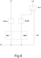
Figs. 6 and7 are diagrams that show two variants of the second embodiment ofFig.5 , respectively analogous to the variants ofFigs.3 and4 ; -
Fig.8 is a diagram that shows a third embodiment of the heating system similar to the first embodiment ofFig.2 , but with three-phase power supply; -
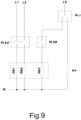
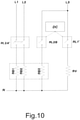
Figs. 9 and10 are diagrams that show two variants of the third embodiment ofFig.8 , respectively analogous to the variants ofFigs.3 and4 ; and -
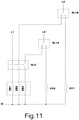
Fig.11 is a diagram that shows a fourth embodiment of the heating system similar to the third embodiment ofFig.8 , but including a plurality of resistances both in the boiler and in the tank. - Referring to
Fig.1 , there is seen that an industrial dishwasher traditionally includes a washing tank in which thewashing sprayers 1 and rinsingsprayers 2 are arranged, fed respectively by awashing pump 3, connected to the collectingsump 4, and by arinsing pump 5 connected to aboiler 6. As mentioned before, the washing water that is collected at the bottom of the tank is heated by a resistance RV that can be positioned insidesump 4, as shown inFig.1 , but also in the lower part of the tank or in a pipe placed in series with thewashing pump 3 in the washing circuit. Similarly, the water inboiler 6 is heated by a resistance RB placed inside it which in reality is formed by a plurality of resistances, for example two resistances RB1, RB2 in the first two embodiments (Figs.2-7 ) and three resistances RB1, RB2, RB3 in the third embodiment (Figs.8-10 ). - The main innovative aspect of the industrial dishwasher according to the present invention lies in the presence of a control circuit for the tank and boiler heating devices which supplies the maximum power available to the boiler when the heating of the water in the tank is not required, while when the supply of the tank heating device is required then the power of the boiler heating device is automatically reduced by an amount equal to or greater than the power of the tank heating device.
- In the first embodiment with single-phase power supply illustrated in
figures 2 to 4 , the heating power of the boiler is divided into tworesistances RB 1, RB2 while the tank has only one resistance RV. With reference again to the previous example of 3000W of maximum available power for the two heating devices, each of the three resistances RB1, RB2, RV can have a power of 1500W so that the heating power of the boiler is maximized by activating simultaneously RB1 and RB2, but there is still the possibility of being able to activate simultaneously both the heating devices of the boiler and the tank by feedingRB 1 and RV while RB2 is automatically deactivated, thus modulating the heating power of the boiler. - For this purpose, the control circuit that carries out the automatic modulation of the power between the boiler and the tank can be either electromechanical or electronic. For example, the first embodiment of
Fig.2 includes two electronically controlled electromechanical contacts RL1, RL2 (relays, contactors) that can be integrated on the electronic control circuit or externally arranged, but still driven by an electronic or electromechanical control. - More specifically, RL1 is a changeover contact (SPDT=Single Pole Double Throw) while RL2 is a normally open double contact in which the contacts move simultaneously, thus resulting either both open or both closed (DPST=Double Pole Single Throw). The changeover contact RL1 ensures that RV and RB2 cannot be activated simultaneously, so that the power required by the two boiler and tank heating devices does not exceed the maximum available power.
- Note that the diagram in
Fig.2 represents only one possible, but not the only, electronic/electromechanical control circuit from which a person skilled in the art can derive other variants, two of which are illustrated infigures 3 and4 . In the diagram inFig.3 , the normally open double contact RL2 is replaced by two normally open single contacts RL2A, RL2B which are independently controlled, the changeover contact RL1 being connected to RL2B. - In the diagram of
Fig.4 , also the changeover contact RL1 is replaced by a normally open single contact RL1', therefore in this case there is a control device DC, of hardware and/or software type, that controls contacts RL1' and RL2B in order to guarantee the non-simultaneous activation of RV and RB2. - In the second embodiment with two-phase power supply shown in
figures 5 to 7 , the diagrams remain substantially unchanged with respect to those of the correspondingfigures 2 to 4 , with the only difference that the first phase line L1 feeds resistance RB1 and the second phase line L2 feeds resistances RB2 and RV. - In the third embodiment with three-phase power supply shown in
figures 8 to 10 , the main difference is given by the presence in the boiler of three resistances RB1, RB2, RB3 fed respectively by the three phase lines L1, L2, L3 with the latter that also feeds the tank resistance RV correlated with RB3. In this case, the normally open double contact RL2 is replaced by a normally open triple contact RL2' in the diagram inFig.8 , equivalent to the diagrams infigures 2 and5 , which contact RL2' is in turn replaced by a normally open double contact RL2A' and a normally open single contact RL2B in the diagrams infigures 9 and10 . - In the diagram of
Fig.10 , similarly to the diagrams offigures 4 and7 , the changeover contact RL1 is replaced by a normally open single contact RL1', therefore in this case there is a control device DC, of hardware and/or software type, which controls contacts RL1' and RL2B in order to guarantee the non-simultaneous activation of RV and RB3. - A second innovative aspect of the present industrial dishwasher is the possibility to increase the flexibility of modulation of the power between the boiler and the tank by providing a plurality of resistances also in the tank, each of these resistances being correlated with a boiler resistance for the alternative activation by the control circuit of the heating system. Also in this case, the power of each tank resistance is preferably not higher than the power of the corresponding boiler resistance with which it is correlated, so that the maximum power absorbed by the heating system does not exceed the maximum available power.
- With reference again to the previous example of 3000W of maximum available power for the two heating devices, in a fourth embodiment shown in
Fig.11 with three-phase power supply (similar to the third embodiment ofFig.8 ) the three boiler resistances RB1, RB2, RB3 could, for example, have powers of 1500W, 1000W and 500W respectively. The heating device of the tank could include two resistances RV1, RV2 having respectively powers of 1000W and 500W, correlated respectively with the corresponding resistances RB2, RB3 of equal power in order to be controlled independently through respective changeover contacts RL1B and RL1A. - Such a configuration allows therefore to maximize the boiler heating power activating at the same time its three resistances by closing RL2', but there is still the possibility to activate at the same time both the heating devices of the boiler and the tank at different power levels:
- a) 2500W to the boiler and 500W to the tank, feeding RB1, RB2 and RV2 while RB3 and RV1 are automatically deactivated (RL1A closed on RV2 and RL1B closed on RL2');
- b) 2000W to the boiler and 1000W to the tank feeding RB1, RB3 and RV1 while RB2 and RV2 are automatically deactivated (RL1A closed on RL2' and RL1B closed on RV1);
- c) 1500W to the boiler and 1500W to the tank feeding RB1, RV1 and RV2 while RB2 and RB3 are automatically deactivated (RL1A closed on RV2 and RL1B closed on RV1).
- From this example it is clear that the power of each resistance, both in the boiler and in the tank, can be chosen according to the level of flexibility and heating capacity that is intended to be obtained with the heating system of this industrial dishwasher. The only two constraints are that the sum of the powers of the resistances of each heating device does not exceed the maximum available power and that the resistances that are correlated to be operated alternatively have the same power, or the resistance of the tank has a lower power.
- Note that this second constraint is based on the assumption that the boiler power is equal to the maximum available power but it would be theoretically possible, although disadvantageous, to have a boiler with a power lower than the maximum, in which case a tank resistance could have a power higher than the corresponding boiler resistance with which it is correlated.
- The example described above of three resistances in the boiler and two resistances in the tank can obviously be generalized to any number of resistances in the boiler and in the tank to further increase the flexibility of the heating system, so as to go beyond the minimum number of two resistances in the boiler and one resistance in the tank as in the first two embodiments. In practice, the tank heating device can include X resistances and the boiler heating device can include Y resistances with 2≤X<Y (so the minimum case is X=2 and Y=3 as in the fourth embodiment). This general concept is illustrated in the diagram in
Fig.11 referring to a three-phase power supply, but it could obviously be applied in the same way also with a single-phase or two-phase power supply. - Note that the transfer of power from the boiler heating device to the tank heating device and vice versa can therefore take place by activating and deactivating multiple pairs of correlated resistances RB/RV, possibly acting on each of these pairs RB/RV at different times in order to progressively vary the power distribution according to the specific needs of the machine's operating cycle.
- It is clear that the embodiments of the dishwasher according to the invention described and illustrated above are only examples susceptible to numerous variations. In particular, the exact type and arrangement of the elements could be varied according to specific construction requirements, creating further variants that are within the reach of a person skilled in the art on the basis of the description given above.
- For example, in the diagrams of
figures 3 ,6 and9 the changeover contact RL1 could directly feed the boiler resistance (RB2 inFigs. 3 ,6 and RB3 inFig.9 ) while the normally open single contact RL2B could be placed in series with the tank resistance RV.
Claims (10)
- Industrial dishwasher comprising a washing tank containing sprayers for washing (1) and rinsing (2), respectively fed with washing water from a washing pump (3) and rinsing water from a rinsing pump (5), and a water heating system comprising a washing water heating device with one or more resistances (RV) and a rinsing water heating device with two or more resistances (RB), as well as a control circuit controlling the operation of said water heating system, characterized in that at least one resistance (RV) of said washing water heating device is correlated with a resistance (RB) of said rinsing water heating device so that the activation of the latter automatically implies the deactivation of the former and vice versa, and in that said correlated resistances (RB, RV) are either electrically connected together or commonly controlled such that they are not activated simultaneously and their activation is mutually exclusive.
- Industrial dishwasher according to claim 1, characterized in that the control circuit includes at least one normally open contact, of single type (RL1', RL2B) or multiple type (RL2, RL2'), that in the closed position connects to at least one resistance (RB) of the rinsing water heating device which is correlated with a resistance (RV) of the washing water heating device, and at least one changeover contact (RL1) that on a first output connects directly to said resistance (RV) of the washing water heating device and on a second output connects to said normally open contact, and/or the control circuit includes a control device (DC) of hardware and/or software type connected to at least one normally open contact that in the closed position connects to at least one resistance (RB) of the rinsing water heating device which is correlated with a resistance (RV) of the washing water heating device, and said control device (DC) is also connected to at least one other normally open contact that in the closed position connects to said resistance (RV) of the washing water heating device, in such a way as to prevent the simultaneous activation of the correlated resistances (RB, RV).
- Industrial dishwasher according to claim 2, characterized in that its power supply is single-phase (L) or two-phase (L1, L2), the washing water heating device is equipped with one resistance (RV), the rinsing water heating device is equipped with two resistances (RB1, RB2) and the control circuit includes a changeover contact (RL1) that on a first output connects directly to said resistance (RV) of the washing water heating device and on a second output connects to a normally open contact of single type (RL2B) or double type (RL2) that in the closed position connects to a resistance (RB2) of the rinsing water heating device that is correlated with the resistance (RV) of the washing water heating device.
- Industrial dishwasher according to claim 2, characterized in that its power supply is single-phase (L) or two-phase (L1, L2), the washing water heating device is equipped with one resistance (RV), the rinsing water heating device is equipped with two resistances (RB1, RB2) and the control circuit includes a respective normally open single contact (RL1', RL2A, RL2B) for each of said three resistances (RV, RB1, RB2), as well as a control device (DC) of hardware and/or software type connected to the normally open single contact (RL1') of said resistance (RV) of the washing water heating device and to the normally open single contact (RL2B) of a resistance (RB2) of the rinsing water heating device which is correlated with the resistance (RV) of the washing water heating device so as to prevent their simultaneous activation.
- Industrial dishwasher according to claim 2, characterized in that its power supply is three-phase (L1, L2, L3), the washing water heating device is equipped with one resistance (RV), the rinsing water heating device is equipped with three resistances (RB1, RB2, RB3) and the control circuit includes a changeover contact (RL1) that on a first output connects directly to said resistance (RV) of the washing water heating device and on a second output connects to a normally open contact of single type (RL2B) or triple type (RL2') that in the closed position connects to a resistance (RB3) of the rinsing water heating device that is correlated with the resistance (RV) of the washing water heating device.
- Industrial dishwasher according to claim 2, characterized in that its power supply is three-phase (L1, L2, L3), the washing water heating device is equipped with one resistance (RV), the rinsing water heating device is equipped with three resistances (RB1, RB2, RB3) and the control circuit includes a normally open double contact (RL2A') for two (RB 1, RB2) of said three resistances of the rinsing water heating device and a respective normally open single contact (RL1', RL2B) for said resistance (RV) of the washing water heating device and for the third resistance (RB3) of the rinsing water heating device that is correlated with the latter, as well as a control device (DC) of hardware and/or software type connected to said two normally open single contacts (RL1', RL2B) so as to prevent the simultaneous activation of the resistance (RV) of the washing water heating device and of said third resistance (RB3) of the rinsing water heating device.
- Industrial dishwasher according to claim 2, characterized in that the washing water heating device is equipped with a number X of resistances (RV1, RV2, ...RVX) and the rinsing water heating device is equipped with a number Y of resistances (RB1, RB2, RB3, ...RBY) with 2≤X<Y, each of said resistances (RV1, RV2, ...RVX) of the washing water heating device being correlated with a resistance (RB1, RB2, RB3, ...RBY) of the rinsing water heating device, the control circuit being able to independently control each pair of correlated resistances so that they are not activated simultaneously.
- Industrial dishwasher according to any of the preceding claims, characterized in that the correlated resistances (RB, RV) have the same power or the resistance (RV) of the washing water heating device has a lower power than the resistance (RB) of the rinsing water heating device with which it is correlated.
- Method of operation of an industrial dishwasher according to any of the preceding claims, characterized in that the control circuit supplies the maximum available power to the rinsing water heating device when heating of the washing water is not required, whereas when heating of the washing water is required then the control circuit reduces the power supplied to the rinsing water heating device by an amount equal to or greater than the power supplied to the washing water heating device.
- Method of operation according to claim 9 when the industrial dishwasher being operated is according to claim 7, characterized in that the transfer of power from the rinsing water heating device to the washing water heating device and vice versa is carried out by activating and deactivating multiple pairs of correlated resistances (RB, RV), possibly acting on each of said pairs (RB, RV) at different times.
Priority Applications (2)
| Application Number | Priority Date | Filing Date | Title |
|---|---|---|---|
| EP19425032.0A EP3733039B1 (en) | 2019-05-02 | 2019-05-02 | Industrial dishwasher with variable water heating system |
| PL19425032T PL3733039T3 (en) | 2019-05-02 | 2019-05-02 | Industrial dishwasher with variable water heating system |
Applications Claiming Priority (1)
| Application Number | Priority Date | Filing Date | Title |
|---|---|---|---|
| EP19425032.0A EP3733039B1 (en) | 2019-05-02 | 2019-05-02 | Industrial dishwasher with variable water heating system |
Publications (2)
| Publication Number | Publication Date |
|---|---|
| EP3733039A1 EP3733039A1 (en) | 2020-11-04 |
| EP3733039B1 true EP3733039B1 (en) | 2022-01-26 |
Family
ID=67145759
Family Applications (1)
| Application Number | Title | Priority Date | Filing Date |
|---|---|---|---|
| EP19425032.0A Active EP3733039B1 (en) | 2019-05-02 | 2019-05-02 | Industrial dishwasher with variable water heating system |
Country Status (2)
| Country | Link |
|---|---|
| EP (1) | EP3733039B1 (en) |
| PL (1) | PL3733039T3 (en) |
Family Cites Families (4)
| Publication number | Priority date | Publication date | Assignee | Title |
|---|---|---|---|---|
| US4315140A (en) * | 1979-09-19 | 1982-02-09 | Avtec Industries, Inc. | Energy saving dishwasher |
| DE102004046758A1 (en) * | 2004-09-24 | 2006-04-06 | Meiko Maschinenbau Gmbh & Co. Kg | Method and arrangement for energy-saving operation of dishwashers |
| DE202007018050U1 (en) * | 2007-12-27 | 2008-03-20 | V - Zug Ag | Domestic appliance, in particular dishwasher, with clocked continuous heater |
| US8218955B2 (en) * | 2008-12-30 | 2012-07-10 | Hatco Corporation | Method and system for reducing response time in booster water heating applications |
-
2019
- 2019-05-02 PL PL19425032T patent/PL3733039T3/en unknown
- 2019-05-02 EP EP19425032.0A patent/EP3733039B1/en active Active
Also Published As
| Publication number | Publication date |
|---|---|
| PL3733039T3 (en) | 2022-05-09 |
| EP3733039A1 (en) | 2020-11-04 |
Similar Documents
| Publication | Publication Date | Title |
|---|---|---|
| CN101084400B (en) | Operation method of flow-through heating | |
| US7884498B2 (en) | Method and arrangement for the energy-saving operation of dishwashers | |
| EP2830476B1 (en) | Dishwasher and method of operating dishwasher | |
| EP0775463B1 (en) | Dishwasher and control therefor | |
| US4225812A (en) | Electric motor control system | |
| EP2433547B1 (en) | Dishwasher with auto hot start | |
| CN103154836B (en) | There are the household electrical appliance of the control device of the electric flux supply system for having associated data network and make the control device of household electrical appliance in the method for this energy supply online operation | |
| ES2709876T3 (en) | Dishwasher for operation in different voltage networks | |
| EP0547011B1 (en) | A washing method for a dishwashing machine of industrial type | |
| CN111779078A (en) | Control system and control method of integrated water tank | |
| EP3733039A1 (en) | Industrial dishwasher with variable water heating system | |
| US20230121850A1 (en) | Connected dishwasher and water heater appliances | |
| US9186035B2 (en) | Method of operating a heater in a dishwasher | |
| EP2875410B1 (en) | Control circuit for self-turn-off of an automatic machine | |
| DK2074922T3 (en) | Household appliance, especially dishwasher, with tactile pass-through heater | |
| EP2878250B1 (en) | Method of operating a water-circulating household appliance | |
| EP3095372B1 (en) | Dish washer with efficient heating system | |
| US20070120518A1 (en) | Electric motor controller for a domestic appliance | |
| CN213062229U (en) | Control system of integrated water tank | |
| JP4284835B2 (en) | Cooker | |
| CN111671371A (en) | Method and device for determining heating mode of dishwasher and storage medium | |
| EP2966213B1 (en) | Electrical appliance with an electrical resistance heating element and method for operating an electrical appliance | |
| JP2002051958A (en) | Dishwasher | |
| JPH079253U (en) | Dishwasher | |
| JPH07298490A (en) | Control device for electric appliances |
Legal Events
| Date | Code | Title | Description |
|---|---|---|---|
| PUAI | Public reference made under article 153(3) epc to a published international application that has entered the european phase |
Free format text: ORIGINAL CODE: 0009012 |
|
| STAA | Information on the status of an ep patent application or granted ep patent |
Free format text: STATUS: THE APPLICATION HAS BEEN PUBLISHED |
|
| AK | Designated contracting states |
Kind code of ref document: A1 Designated state(s): AL AT BE BG CH CY CZ DE DK EE ES FI FR GB GR HR HU IE IS IT LI LT LU LV MC MK MT NL NO PL PT RO RS SE SI SK SM TR |
|
| AX | Request for extension of the european patent |
Extension state: BA ME |
|
| STAA | Information on the status of an ep patent application or granted ep patent |
Free format text: STATUS: REQUEST FOR EXAMINATION WAS MADE |
|
| 17P | Request for examination filed |
Effective date: 20210504 |
|
| RBV | Designated contracting states (corrected) |
Designated state(s): AL AT BE BG CH CY CZ DE DK EE ES FI FR GB GR HR HU IE IS IT LI LT LU LV MC MK MT NL NO PL PT RO RS SE SI SK SM TR |
|
| GRAP | Despatch of communication of intention to grant a patent |
Free format text: ORIGINAL CODE: EPIDOSNIGR1 |
|
| STAA | Information on the status of an ep patent application or granted ep patent |
Free format text: STATUS: GRANT OF PATENT IS INTENDED |
|
| INTG | Intention to grant announced |
Effective date: 20210819 |
|
| GRAS | Grant fee paid |
Free format text: ORIGINAL CODE: EPIDOSNIGR3 |
|
| GRAA | (expected) grant |
Free format text: ORIGINAL CODE: 0009210 |
|
| STAA | Information on the status of an ep patent application or granted ep patent |
Free format text: STATUS: THE PATENT HAS BEEN GRANTED |
|
| AK | Designated contracting states |
Kind code of ref document: B1 Designated state(s): AL AT BE BG CH CY CZ DE DK EE ES FI FR GB GR HR HU IE IS IT LI LT LU LV MC MK MT NL NO PL PT RO RS SE SI SK SM TR |
|
| REG | Reference to a national code |
Ref country code: GB Ref legal event code: FG4D |
|
| REG | Reference to a national code |
Ref country code: CH Ref legal event code: EP |
|
| REG | Reference to a national code |
Ref country code: AT Ref legal event code: REF Ref document number: 1464613 Country of ref document: AT Kind code of ref document: T Effective date: 20220215 |
|
| REG | Reference to a national code |
Ref country code: IE Ref legal event code: FG4D |
|
| REG | Reference to a national code |
Ref country code: DE Ref legal event code: R096 Ref document number: 602019011232 Country of ref document: DE |
|
| REG | Reference to a national code |
Ref country code: NL Ref legal event code: FP |
|
| REG | Reference to a national code |
Ref country code: LT Ref legal event code: MG9D |
|
| REG | Reference to a national code |
Ref country code: AT Ref legal event code: MK05 Ref document number: 1464613 Country of ref document: AT Kind code of ref document: T Effective date: 20220126 |
|
| PG25 | Lapsed in a contracting state [announced via postgrant information from national office to epo] |
Ref country code: SE Free format text: LAPSE BECAUSE OF FAILURE TO SUBMIT A TRANSLATION OF THE DESCRIPTION OR TO PAY THE FEE WITHIN THE PRESCRIBED TIME-LIMIT Effective date: 20220126 Ref country code: RS Free format text: LAPSE BECAUSE OF FAILURE TO SUBMIT A TRANSLATION OF THE DESCRIPTION OR TO PAY THE FEE WITHIN THE PRESCRIBED TIME-LIMIT Effective date: 20220126 Ref country code: PT Free format text: LAPSE BECAUSE OF FAILURE TO SUBMIT A TRANSLATION OF THE DESCRIPTION OR TO PAY THE FEE WITHIN THE PRESCRIBED TIME-LIMIT Effective date: 20220526 Ref country code: NO Free format text: LAPSE BECAUSE OF FAILURE TO SUBMIT A TRANSLATION OF THE DESCRIPTION OR TO PAY THE FEE WITHIN THE PRESCRIBED TIME-LIMIT Effective date: 20220426 Ref country code: LT Free format text: LAPSE BECAUSE OF FAILURE TO SUBMIT A TRANSLATION OF THE DESCRIPTION OR TO PAY THE FEE WITHIN THE PRESCRIBED TIME-LIMIT Effective date: 20220126 Ref country code: HR Free format text: LAPSE BECAUSE OF FAILURE TO SUBMIT A TRANSLATION OF THE DESCRIPTION OR TO PAY THE FEE WITHIN THE PRESCRIBED TIME-LIMIT Effective date: 20220126 Ref country code: ES Free format text: LAPSE BECAUSE OF FAILURE TO SUBMIT A TRANSLATION OF THE DESCRIPTION OR TO PAY THE FEE WITHIN THE PRESCRIBED TIME-LIMIT Effective date: 20220126 Ref country code: BG Free format text: LAPSE BECAUSE OF FAILURE TO SUBMIT A TRANSLATION OF THE DESCRIPTION OR TO PAY THE FEE WITHIN THE PRESCRIBED TIME-LIMIT Effective date: 20220426 |
|
| PG25 | Lapsed in a contracting state [announced via postgrant information from national office to epo] |
Ref country code: LV Free format text: LAPSE BECAUSE OF FAILURE TO SUBMIT A TRANSLATION OF THE DESCRIPTION OR TO PAY THE FEE WITHIN THE PRESCRIBED TIME-LIMIT Effective date: 20220126 Ref country code: GR Free format text: LAPSE BECAUSE OF FAILURE TO SUBMIT A TRANSLATION OF THE DESCRIPTION OR TO PAY THE FEE WITHIN THE PRESCRIBED TIME-LIMIT Effective date: 20220427 Ref country code: FI Free format text: LAPSE BECAUSE OF FAILURE TO SUBMIT A TRANSLATION OF THE DESCRIPTION OR TO PAY THE FEE WITHIN THE PRESCRIBED TIME-LIMIT Effective date: 20220126 Ref country code: AT Free format text: LAPSE BECAUSE OF FAILURE TO SUBMIT A TRANSLATION OF THE DESCRIPTION OR TO PAY THE FEE WITHIN THE PRESCRIBED TIME-LIMIT Effective date: 20220126 |
|
| PG25 | Lapsed in a contracting state [announced via postgrant information from national office to epo] |
Ref country code: IS Free format text: LAPSE BECAUSE OF FAILURE TO SUBMIT A TRANSLATION OF THE DESCRIPTION OR TO PAY THE FEE WITHIN THE PRESCRIBED TIME-LIMIT Effective date: 20220526 |
|
| REG | Reference to a national code |
Ref country code: DE Ref legal event code: R097 Ref document number: 602019011232 Country of ref document: DE |
|
| PG25 | Lapsed in a contracting state [announced via postgrant information from national office to epo] |
Ref country code: SM Free format text: LAPSE BECAUSE OF FAILURE TO SUBMIT A TRANSLATION OF THE DESCRIPTION OR TO PAY THE FEE WITHIN THE PRESCRIBED TIME-LIMIT Effective date: 20220126 Ref country code: SK Free format text: LAPSE BECAUSE OF FAILURE TO SUBMIT A TRANSLATION OF THE DESCRIPTION OR TO PAY THE FEE WITHIN THE PRESCRIBED TIME-LIMIT Effective date: 20220126 Ref country code: RO Free format text: LAPSE BECAUSE OF FAILURE TO SUBMIT A TRANSLATION OF THE DESCRIPTION OR TO PAY THE FEE WITHIN THE PRESCRIBED TIME-LIMIT Effective date: 20220126 Ref country code: EE Free format text: LAPSE BECAUSE OF FAILURE TO SUBMIT A TRANSLATION OF THE DESCRIPTION OR TO PAY THE FEE WITHIN THE PRESCRIBED TIME-LIMIT Effective date: 20220126 Ref country code: DK Free format text: LAPSE BECAUSE OF FAILURE TO SUBMIT A TRANSLATION OF THE DESCRIPTION OR TO PAY THE FEE WITHIN THE PRESCRIBED TIME-LIMIT Effective date: 20220126 Ref country code: CZ Free format text: LAPSE BECAUSE OF FAILURE TO SUBMIT A TRANSLATION OF THE DESCRIPTION OR TO PAY THE FEE WITHIN THE PRESCRIBED TIME-LIMIT Effective date: 20220126 |
|
| PG25 | Lapsed in a contracting state [announced via postgrant information from national office to epo] |
Ref country code: AL Free format text: LAPSE BECAUSE OF FAILURE TO SUBMIT A TRANSLATION OF THE DESCRIPTION OR TO PAY THE FEE WITHIN THE PRESCRIBED TIME-LIMIT Effective date: 20220126 |
|
| PLBE | No opposition filed within time limit |
Free format text: ORIGINAL CODE: 0009261 |
|
| STAA | Information on the status of an ep patent application or granted ep patent |
Free format text: STATUS: NO OPPOSITION FILED WITHIN TIME LIMIT |
|
| REG | Reference to a national code |
Ref country code: CH Ref legal event code: PL |
|
| 26N | No opposition filed |
Effective date: 20221027 |
|
| REG | Reference to a national code |
Ref country code: BE Ref legal event code: MM Effective date: 20220531 |
|
| PG25 | Lapsed in a contracting state [announced via postgrant information from national office to epo] |
Ref country code: MC Free format text: LAPSE BECAUSE OF FAILURE TO SUBMIT A TRANSLATION OF THE DESCRIPTION OR TO PAY THE FEE WITHIN THE PRESCRIBED TIME-LIMIT Effective date: 20220126 Ref country code: LU Free format text: LAPSE BECAUSE OF NON-PAYMENT OF DUE FEES Effective date: 20220502 Ref country code: LI Free format text: LAPSE BECAUSE OF NON-PAYMENT OF DUE FEES Effective date: 20220531 Ref country code: CH Free format text: LAPSE BECAUSE OF NON-PAYMENT OF DUE FEES Effective date: 20220531 |
|
| PG25 | Lapsed in a contracting state [announced via postgrant information from national office to epo] |
Ref country code: SI Free format text: LAPSE BECAUSE OF FAILURE TO SUBMIT A TRANSLATION OF THE DESCRIPTION OR TO PAY THE FEE WITHIN THE PRESCRIBED TIME-LIMIT Effective date: 20220126 |
|
| PG25 | Lapsed in a contracting state [announced via postgrant information from national office to epo] |
Ref country code: IE Free format text: LAPSE BECAUSE OF NON-PAYMENT OF DUE FEES Effective date: 20220502 |
|
| PG25 | Lapsed in a contracting state [announced via postgrant information from national office to epo] |
Ref country code: BE Free format text: LAPSE BECAUSE OF NON-PAYMENT OF DUE FEES Effective date: 20220531 |
|
| P01 | Opt-out of the competence of the unified patent court (upc) registered |
Effective date: 20230606 |
|
| PG25 | Lapsed in a contracting state [announced via postgrant information from national office to epo] |
Ref country code: MK Free format text: LAPSE BECAUSE OF FAILURE TO SUBMIT A TRANSLATION OF THE DESCRIPTION OR TO PAY THE FEE WITHIN THE PRESCRIBED TIME-LIMIT Effective date: 20220126 Ref country code: CY Free format text: LAPSE BECAUSE OF FAILURE TO SUBMIT A TRANSLATION OF THE DESCRIPTION OR TO PAY THE FEE WITHIN THE PRESCRIBED TIME-LIMIT Effective date: 20220126 |
|
| PG25 | Lapsed in a contracting state [announced via postgrant information from national office to epo] |
Ref country code: HU Free format text: LAPSE BECAUSE OF FAILURE TO SUBMIT A TRANSLATION OF THE DESCRIPTION OR TO PAY THE FEE WITHIN THE PRESCRIBED TIME-LIMIT; INVALID AB INITIO Effective date: 20190502 |
|
| PG25 | Lapsed in a contracting state [announced via postgrant information from national office to epo] |
Ref country code: TR Free format text: LAPSE BECAUSE OF FAILURE TO SUBMIT A TRANSLATION OF THE DESCRIPTION OR TO PAY THE FEE WITHIN THE PRESCRIBED TIME-LIMIT Effective date: 20220126 |
|
| PG25 | Lapsed in a contracting state [announced via postgrant information from national office to epo] |
Ref country code: MT Free format text: LAPSE BECAUSE OF FAILURE TO SUBMIT A TRANSLATION OF THE DESCRIPTION OR TO PAY THE FEE WITHIN THE PRESCRIBED TIME-LIMIT Effective date: 20220126 |
|
| PGFP | Annual fee paid to national office [announced via postgrant information from national office to epo] |
Ref country code: NL Payment date: 20250521 Year of fee payment: 7 |
|
| PGFP | Annual fee paid to national office [announced via postgrant information from national office to epo] |
Ref country code: PL Payment date: 20250425 Year of fee payment: 7 Ref country code: DE Payment date: 20250521 Year of fee payment: 7 |
|
| PGFP | Annual fee paid to national office [announced via postgrant information from national office to epo] |
Ref country code: GB Payment date: 20250527 Year of fee payment: 7 |
|
| PGFP | Annual fee paid to national office [announced via postgrant information from national office to epo] |
Ref country code: IT Payment date: 20250515 Year of fee payment: 7 |
|
| PGFP | Annual fee paid to national office [announced via postgrant information from national office to epo] |
Ref country code: FR Payment date: 20250528 Year of fee payment: 7 |