EP3732973B1 - Device for bending dough pieces - Google Patents
Device for bending dough pieces Download PDFInfo
- Publication number
- EP3732973B1 EP3732973B1 EP19172559.7A EP19172559A EP3732973B1 EP 3732973 B1 EP3732973 B1 EP 3732973B1 EP 19172559 A EP19172559 A EP 19172559A EP 3732973 B1 EP3732973 B1 EP 3732973B1
- Authority
- EP
- European Patent Office
- Prior art keywords
- conveyor
- gate
- dough
- engaging means
- dough piece
- Prior art date
- Legal status (The legal status is an assumption and is not a legal conclusion. Google has not performed a legal analysis and makes no representation as to the accuracy of the status listed.)
- Active
Links
Images

Classifications
-
- A—HUMAN NECESSITIES
- A21—BAKING; EDIBLE DOUGHS
- A21C—MACHINES OR EQUIPMENT FOR MAKING OR PROCESSING DOUGHS; HANDLING BAKED ARTICLES MADE FROM DOUGH
- A21C9/00—Other apparatus for handling dough or dough pieces
- A21C9/08—Depositing, arranging and conveying apparatus for handling pieces, e.g. sheets of dough
- A21C9/088—Folding or bending discrete dough pieces or dough strips
-
- A—HUMAN NECESSITIES
- A21—BAKING; EDIBLE DOUGHS
- A21C—MACHINES OR EQUIPMENT FOR MAKING OR PROCESSING DOUGHS; HANDLING BAKED ARTICLES MADE FROM DOUGH
- A21C3/00—Machines or apparatus for shaping batches of dough before subdivision
- A21C3/06—Machines for coiling sheets of dough, e.g. for producing rolls
Definitions
- the present invention relates to a device for bending dough pieces, more in particular a device for bending croissants.
- Devices for this purpose are well known in the art, and several solutions have been proposed and manufactured throughout the years.
- Another disadvantage of the state of the art equipment is that they are less suitable for bending filled croissants, that is croissants filled with a (semi)fluid fill, at least before baking, for instance chocolate or marmalade.
- the devices tend to exert too much force on the croissant at those places where the filling is placed, which leads to displacement of the filling to undesired places or even tear of the croissant.
- the invention thereto proposes a device for bending dough pieces, in particular croissants, comprising:- A first conveyor, for transporting dough pieces in a direction of conveyance;- At least a first gate, defining a passage with a first width, smaller than the width of the conveyor, for the dough pieces; wherein the gate is the point where the bending takes place;- at least two engaging means, for engaging a dough piece entering the passage and exerting a force on the dough piece with a directional component toward the first conveyor, wherein both engaging means are spaced apart from each other, dimensioned such that it engages the dough piece at the two locations, but not in between them, thus leaving a gap in between them, wherein the front of the gate comprises at least one pillar, rotatable about its length axis, extending with a directional component perpendicular to the first conveyor.
- the first conveyor may be an endless conveyor, on which dough pieces are transported in a transport direction.
- the dough pieces may be arranged in one or more parallel lanes.
- the plane of conveyance may normally be a horizontal plane.
- the gate may define only the width of the passage, that is: it does not necessarily form a bridge over the conveyor, and the height over which it defines said width may be limited to a height level of the dough products the device is intended for. In practice, the height may for instance be between one fourth and once the width of the gate.
- the engaging means serve for keeping the dough piece in position with respect to the first conveyor, at least at the position where it is engaged by the engaging means, but at a result also in the position in between the engaging means.
- the first and second engaging means according to the present invention are separate pieces of the device, or a single piece, dimensioned such that it engages the dough piece at the two locations, but not in between them.
- the first and second engaging means serve to precisely define the bending locations of the dough piece, and to avoid a V-shaped dough piece.
- a first advantage over the prior art, characterised by a single engaging means formed by a central wheel, is that the dough pieces are bent following the shape and size of the gate.
- a central fold tends to occur, leading to an undesired V-shaped dough product.
- the device according to the present invention allows to create a C shaped form with two clear bends. This effect is even stronger when the engaging means are placed adjacent to the edges of the passage formed by the gate. Additionally, the dough piece has shown to better remain in its bent position with such placement of the engaging means.
- a second advantage is obtained because the dough piece is not touched in between the engaging means. This avoids any impact on a filling of the dough pieces, which is normally applied in the centre of the dough piece.
- the engaging means are formed by at least one wheel, in particular at least one driven wheel, positioned at a distance above the first conveyor.
- This may be one wheel with an H- or diabolo-shape, or two separate wheels, which may or may not be on the same shaft, and also may or may not be driven by said same shaft.
- the use of wheels has the advantage that in addition to a directional component toward the first conveyor, a directional component along with the direction of conveyance can be applied on the dough pieces, which avoids damage to the dough pieces due to tear.
- the gate may comprise a third and a second conveyor, each having a surface of conveyance, both surfaces facing each other and arranged with a directional component perpendicular to the first conveyor.
- third and a second conveyor are perpendicular to the first conveyor, and preferably also close to or adjacent to the surface of the first conveyor.
- the second and third conveyor may have a mutually mirrored configuration.
- the front of the gate comprises at least one pillar, rotatable about its length axis, extending with a directional component perpendicular to the first conveyor.
- the pillar preferably has a cylindrical shape, and serves to smoothly guide the bent ends of the dough piece into the gate.
- the device comprises a second gate, arranged downstream of the first gate, as an extension of the first gate.
- Such second gate may be applied for various reasons.
- a first reason may be to further bend a dough piece, in particular for croissants of which the legs are to be pinched against or on top of each other.
- the second gate may be dimensioned with a with a smaller width than the first gate.
- This second gate may comprise a fourth and fifth conveyor, and at least one engaging means, for engaging a dough piece entering the passage and exerting a force on the dough piece with a directional component toward the first conveyor.
- the engaging means may be at least one wheel, but a similar arrangement as the first gate may be applied too.
- Such third gate may then comprise a sixth and seventh conveyor, and at least one engaging means, for engaging a dough piece entering the passage and exerting a force on the dough piece with a directional component toward the first conveyor.
- At least one of the pairs of conveyors formed by the second and the third conveyor or the fourth and the fifth conveyor or the sixth and seventh conveyor may be positioned in a converging way, that is, with a smaller opening at its downstream end than at its upstream end.
- Such pair of conveyors may gradually shape a dough piece and have a more stable formed product as a result.
- the height between the surface of the conveyor and the engaging means may be adjustable, and the width between the engaging means as well.
- the device may be equipped with multiple gates next to each other, perpendicular to the direction of conveyance.
- the width between a pair of conveyors formed by the second and the third conveyor or the fourth and the fifth conveyor or the sixth and seventh conveyor may be adjustable.
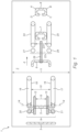
- Figure 1 shows a schematic top view on a device for bending dough pieces, in particular croissants, comprising a first conveyor 2 for transporting dough pieces 3, 5, 6, 7, 8 in a direction of conveyance 4.
- the device 1 comprises a first gate 9, defining a passage with a first width 10, smaller than the width 11 of the conveyor 2, for the dough pieces 3, 5, 6, 7, 8.
- the first gate 9 is provided with two engaging means 12, 13, formed by wheels that are rotatable around axis 14 for engaging a dough piece 5 entering the passage and exerting a force on the dough piece 5 with a directional component toward the first conveyor 2, wherein both engaging means 12, 13 are spaced apart from each other in order to leave a gap 15 in between them.
- the wheels 12, 13 are positioned at a distance above the first conveyor 2.
- the gate 9 comprises a third conveyor 16 and a second conveyor 17, each having a surface of conveyance 18, 19, both surfaces facing each other and arranged with a directional component perpendicular to the (surface of conveyance of the) first conveyor 2.
- the second conveyor may be formed by multiple subsequent conveyors, in particular there may be one more transitions in between.
- the second gate 23 comprises a fourth and fifth conveyor 24, 25, and at least one engaging means 26, for engaging a dough piece entering the passage and exerting a force on the dough piece 6 with a directional component toward the first conveyor 2.
- the front of the gate 9 comprises two pillars 27, 28, rotatable about their length axis, extending with a directional component perpendicular to the first conveyor 2.
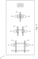
- FIG. 3 shows a third embodiment 41 of a device according to the present invention wherein a pair of conveyors 42, 43 are positioned in a converging way, that is, with a smaller opening at its downstream end than at its upstream end.
- the gate comprises two engaging means 44, 45 formed by wheels, for engaging a dough piece entering the passage and exerting a force on the dough piece 49 with a directional component toward the first conveyor, wherein both engaging means are spaced apart from each other in order to leave a gap 48 in between them.
- the device comprises a third engagement means 46, formed by a wheel as well, for stabilising the position of the dough piece 50.
- Figure 4 shows a fourth embodiment 57 of a device according to the present invention, wherein the gates comprise only pillars 51, 52, 53, 54, 55, 56, besides engaging means 58, 59, 60, 61, 62.
- This configuration may be used to obtain a very compact device, which is suitable for dough pieces that have the property of keeping their shape without support.
Landscapes
- Life Sciences & Earth Sciences (AREA)
- Engineering & Computer Science (AREA)
- Food Science & Technology (AREA)
- Manufacturing And Processing Devices For Dough (AREA)
- Bakery Products And Manufacturing Methods Therefor (AREA)
Description
- The present invention relates to a device for bending dough pieces, more in particular a device for bending croissants. Devices for this purpose are well known in the art, and several solutions have been proposed and manufactured throughout the years.
- In a classic way, croissants are made by rolling up an essentially triangular dough piece, starting at the basis and ending at a tip. However, nowadays, croissants that are bent in half-moon or C shape have become common too, as well as croissants with the tips of their legs bent against or on top of each other. These latter two versions need to be bent further than the C-shaped ones, and an essentially annular shape is required. However, the equipment according to the state of the art has appeared not to be suitable to fulfil this need.
- Another disadvantage of the state of the art equipment is that they are less suitable for bending filled croissants, that is croissants filled with a (semi)fluid fill, at least before baking, for instance chocolate or marmalade. The devices tend to exert too much force on the croissant at those places where the filling is placed, which leads to displacement of the filling to undesired places or even tear of the croissant.
-
US 5 460 081 A andDE 100 34 177 disclose known devices for bending dough pieces. - It is therefore a goal of the present invention to provide a device for bending dough pieces that takes away at least some of the disadvantages of the prior art, or at least to provide a useful alternative thereto.
- The invention thereto proposes a device for bending dough pieces, in particular croissants, comprising:- A first conveyor, for transporting dough pieces in a direction of conveyance;- At least a first gate, defining a passage with a first width, smaller than the width of the conveyor, for the dough pieces; wherein the gate is the point where the bending takes place;- at least two engaging means, for engaging a dough piece entering the passage and exerting a force on the dough piece with a directional component toward the first conveyor, wherein both engaging means are spaced apart from each other, dimensioned such that it engages the dough piece at the two locations, but not in between them, thus leaving a gap in between them, wherein the front of the gate comprises at least one pillar, rotatable about its length axis, extending with a directional component perpendicular to the first conveyor.
- The first conveyor may be an endless conveyor, on which dough pieces are transported in a transport direction. The dough pieces may be arranged in one or more parallel lanes. The plane of conveyance may normally be a horizontal plane. The gate may define only the width of the passage, that is: it does not necessarily form a bridge over the conveyor, and the height over which it defines said width may be limited to a height level of the dough products the device is intended for. In practice, the height may for instance be between one fourth and once the width of the gate. The engaging means serve for keeping the dough piece in position with respect to the first conveyor, at least at the position where it is engaged by the engaging means, but at a result also in the position in between the engaging means. The first and second engaging means according to the present invention are separate pieces of the device, or a single piece, dimensioned such that it engages the dough piece at the two locations, but not in between them. As a result, or in other words, the first and second engaging means serve to precisely define the bending locations of the dough piece, and to avoid a V-shaped dough piece.
- A first advantage over the prior art, characterised by a single engaging means formed by a central wheel, is that the dough pieces are bent following the shape and size of the gate. When bent with prior art devices, a central fold tends to occur, leading to an undesired V-shaped dough product. The device according to the present invention allows to create a C shaped form with two clear bends. This effect is even stronger when the engaging means are placed adjacent to the edges of the passage formed by the gate. Additionally, the dough piece has shown to better remain in its bent position with such placement of the engaging means.
- A second advantage is obtained because the dough piece is not touched in between the engaging means. This avoids any impact on a filling of the dough pieces, which is normally applied in the centre of the dough piece.
- In an embodiment, the engaging means are formed by at least one wheel, in particular at least one driven wheel, positioned at a distance above the first conveyor. This may be one wheel with an H- or diabolo-shape, or two separate wheels, which may or may not be on the same shaft, and also may or may not be driven by said same shaft. The use of wheels has the advantage that in addition to a directional component toward the first conveyor, a directional component along with the direction of conveyance can be applied on the dough pieces, which avoids damage to the dough pieces due to tear.
- The gate may comprise a third and a second conveyor, each having a surface of conveyance, both surfaces facing each other and arranged with a directional component perpendicular to the first conveyor. In particular, third and a second conveyor are perpendicular to the first conveyor, and preferably also close to or adjacent to the surface of the first conveyor. With respect to a centre line through the gate, in the direction of conveyance of the first conveyor, the second and third conveyor may have a mutually mirrored configuration.
- According to the present invention the front of the gate comprises at least one pillar, rotatable about its length axis, extending with a directional component perpendicular to the first conveyor. The pillar preferably has a cylindrical shape, and serves to smoothly guide the bent ends of the dough piece into the gate.
- In a further embodiment of according to the present invention, the device comprises a second gate, arranged downstream of the first gate, as an extension of the first gate. Such second gate may be applied for various reasons. A first reason may be to further bend a dough piece, in particular for croissants of which the legs are to be pinched against or on top of each other. In that case the second gate may be dimensioned with a with a smaller width than the first gate.
- It may also be beneficial to use a second gate to anchor the bent form better in the dough piece. It appears that dough pieces have less tendency to bend back in their original shape when they leave a first bending stage. By repeating the step, this disadvantage can be solved.
- This second gate may comprise a fourth and fifth conveyor, and at least one engaging means, for engaging a dough piece entering the passage and exerting a force on the dough piece with a directional component toward the first conveyor. The engaging means may be at least one wheel, but a similar arrangement as the first gate may be applied too.
- It is even possible to provide the device with a third gate, with a smaller width than the second gate, arranged downstream of the second gate, as an extension of the second gate. Such third gate may then comprise a sixth and seventh conveyor, and at least one engaging means, for engaging a dough piece entering the passage and exerting a force on the dough piece with a directional component toward the first conveyor.
- At least one of the pairs of conveyors formed by the second and the third conveyor or the fourth and the fifth conveyor or the sixth and seventh conveyor may be positioned in a converging way, that is, with a smaller opening at its downstream end than at its upstream end. Such pair of conveyors may gradually shape a dough piece and have a more stable formed product as a result.
- The first gate may be preceded by a stage for rolling up dough pieces, in particular croissants, and the last gate may be succeeded by a pinch unit, for pinching the free ends of the bent dough product against or on top of each other.
- Furthermore, the height between the surface of the conveyor and the engaging means may be adjustable, and the width between the engaging means as well. The device may be equipped with multiple gates next to each other, perpendicular to the direction of conveyance. Also the width between a pair of conveyors formed by the second and the third conveyor or the fourth and the fifth conveyor or the sixth and seventh conveyor may be adjustable.
- The invention will now be elucidated into more detail with reference to the following figures. Herein:
-
Figure 1 shows a first embodiment of a device according to the present invention; -
Figure 2 shows a second embodiment of a device according to the present invention; -
Figure 3 shows a third embodiment of a device according to the present invention; and -
Figure 4 shows a first embodiment of a device according to the present invention. -
Figure 1 shows a schematic top view on a device for bending dough pieces, in particular croissants, comprising afirst conveyor 2 for transportingdough pieces conveyance 4. The device 1 comprises afirst gate 9, defining a passage with afirst width 10, smaller than the width 11 of theconveyor 2, for thedough pieces first gate 9 is provided with twoengaging means axis 14 for engaging adough piece 5 entering the passage and exerting a force on thedough piece 5 with a directional component toward thefirst conveyor 2, wherein both engagingmeans gap 15 in between them. Thewheels first conveyor 2. - The
gate 9 comprises athird conveyor 16 and asecond conveyor 17, each having a surface ofconveyance first conveyor 2. Evidently, the second conveyor may be formed by multiple subsequent conveyors, in particular there may be one more transitions in between. - The front of the
gate 9 comprises twopillars first conveyor 2. The device furthermore comprises asecond gate 22, with asmaller width 23 than thefirst gate 9, arranged downstream of thefirst gate 9, as an extension of thefirst gate 9. - The
second gate 23 comprises a fourth andfifth conveyor means 26, for engaging a dough piece entering the passage and exerting a force on the dough piece 6 with a directional component toward thefirst conveyor 2. Also the front of thegate 9 comprises twopillars first conveyor 2. - It is visible that the
croissant 8, that has passed both thefirst gate 9 and thesecond gate 22 has obtained a C-shape with essentially four bends A, B, C, D. -
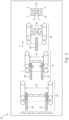
Figure 2 shows a second embodiment of a device according to the present invention, comprising a cascade of three bendingstages widths first stage 30 has two engagement means 36, 37, each formed by a wheel, thesecond stage 31 also has two engagement means, 38, 39, also formed by two wheels and athird stage 32 having only one engagement means formed by onewheel 46. The embodiment from figure two works essentially the same as the one shown infigure 1 , be it that the three stages lead to adough product 40 having six bends A, B, C, D, E, F. It should be noted that the configuration and components of the first andsecond stages first gate 9 fromfigure 1 . The configuration and components of thethird stage 32 may correspond to that of thesecond gate 22 fromfigure 1 . -
Figure 3 shows athird embodiment 41 of a device according to the present invention wherein a pair ofconveyors means dough piece 49 with a directional component toward the first conveyor, wherein both engaging means are spaced apart from each other in order to leave agap 48 in between them. The device comprises a third engagement means 46, formed by a wheel as well, for stabilising the position of thedough piece 50. -
Figure 4 shows afourth embodiment 57 of a device according to the present invention, wherein the gates comprise onlypillars means
Claims (14)
- Device (1) for bending dough pieces (3), in particular croissants, comprising:- A first conveyor (2), for transporting dough pieces (3,5,6,7,8) in a direction of conveyance (4);- At least a first gate (9), defining a passage with a first width (10), smaller than the width (11) of the conveyor (2), for the dough pieces (3,5,6,7,8); wherein the gate (9) is the point where the bending takes place;- at least two engaging means (12,13), for engaging a dough piece (5) entering the passage (10) and exerting a force on the dough piece (5) with a directional component toward the first conveyor (2), wherein both engaging means (12,13) are spaced apart from each other, dimensioned such that it engages the dough piece (5) at the two locations, but not in between them, thus leaving a gap (15) in between them,characterised in that- the front of the gate comprises at least one pillar (20,21), rotatable about its length axis, extending with a directional component perpendicular to the first conveyor (2).
- Device according to claim 1, wherein the engaging means (12,13) are formed by at least one wheel, in particular at least one driven wheel, positioned at a distance above the first conveyor (2).
- Device according to claim 1 or 2, wherein the gate comprises a third and a second conveyor (16,17), each having a surface of conveyance (18,19), both surfaces facing each other and arranged with a directional component perpendicular to the first conveyor (2).
- Device according to any of the preceding claims, comprising a second gate (22), with a smaller width (23) than the first gate (10), arranged downstream of the first gate (9), as an extension of the first gate (9).
- Device according to claim 4, wherein the second gate (22) comprises a fourth and fifth conveyor (24,25), and at least one engaging means, for engaging a dough piece (6) entering the passage (23) and excerting a force on the dough piece (6) with a directional component toward the first conveyor (2).
- Device according to claim 4 or 5, comprising a third gate, with a smaller width (35) than the second gate (34), arranged downstream of the second gate, as an extension of the second gate.
- Device according to claim 6, wherein the third gate comprises a sixth and seventh conveyor, and at least one engaging means (46), for engaging a dough piece entering the passage and exerting a force on the dough piece with a directional component toward the first conveyor (2).
- Device according to any of claims 4-7, wherein at least one of the pairs of conveyors (42,43) formed by the second and the third conveyor or the fourth and the fifth conveyor or the sixth and seventh conveyor are positioned in a converging way, that is, with a smaller opening at its downstream end than at its upstream end.
- Device according to any of the preceding claims, wherein the first gate is preceded by a stage for rolling up dough pieces, in particular croissants.
- Device according to any of the preceding claims, wherein the last gate is succeeded by a pinch unit, for pinching the free ends of the bent dough product against or on top of each other.
- Device according to any of the preceding claims, wherein the height between the surface of the conveyor and the engaging means is adjustable.
- Device according to any of the preceding claims, wherein the width (15) between the engaging means is adjustable.
- Device according to any of the preceding claims, comprising multiple gates next to each other, perpendicular to the direction of conveyance.
- Device according to any of claims 3, 5, 7 or 8, wherein the width between a pair of conveyors formed by the second and the third conveyor (33) or the fourth and the fifth conveyor (34) or the sixth and seventh conveyor (35) is adjustable.
Priority Applications (2)
| Application Number | Priority Date | Filing Date | Title |
|---|---|---|---|
| EP19172559.7A EP3732973B1 (en) | 2019-05-03 | 2019-05-03 | Device for bending dough pieces |
| US16/863,478 US11344033B2 (en) | 2019-05-03 | 2020-04-30 | Device for bending dough pieces |
Applications Claiming Priority (1)
| Application Number | Priority Date | Filing Date | Title |
|---|---|---|---|
| EP19172559.7A EP3732973B1 (en) | 2019-05-03 | 2019-05-03 | Device for bending dough pieces |
Publications (3)
| Publication Number | Publication Date |
|---|---|
| EP3732973A1 EP3732973A1 (en) | 2020-11-04 |
| EP3732973B1 true EP3732973B1 (en) | 2024-07-03 |
| EP3732973C0 EP3732973C0 (en) | 2024-07-03 |
Family
ID=66397142
Family Applications (1)
| Application Number | Title | Priority Date | Filing Date |
|---|---|---|---|
| EP19172559.7A Active EP3732973B1 (en) | 2019-05-03 | 2019-05-03 | Device for bending dough pieces |
Country Status (2)
| Country | Link |
|---|---|
| US (1) | US11344033B2 (en) |
| EP (1) | EP3732973B1 (en) |
Citations (18)
| Publication number | Priority date | Publication date | Assignee | Title |
|---|---|---|---|---|
| GB835240A (en) | 1956-01-27 | 1960-05-18 | Baker Perkins Ltd | Improvements in or relating to methods and means for folding dough pieces |
| AT326065B (en) | 1971-10-07 | 1975-11-25 | Prohaska Franz Ing | DEVICE FOR U- OR SICKLE-SHAPED BENDING OF LONG-MOLDED BAKED PRODUCTS, IN PARTICULAR BAKED PRODUCTS |
| US4741263A (en) | 1985-05-27 | 1988-05-03 | Sadao Ueno | Apparatus and method for producing croissants |
| US4961697A (en) | 1988-02-17 | 1990-10-09 | Machinefabriek C. Rijkaart B.V. | Dough piece bending device |
| US5382154A (en) | 1992-04-27 | 1995-01-17 | Rheon Automatic Machinery Co., Ltd. | Method and device for aligning and bending individual round elongated dough pieces |
| US5460081A (en) | 1993-10-08 | 1995-10-24 | Rheon Automatic Machinery Co., Ltd. | Center-aligning apparatus for croissant dough pieces |
| US5516538A (en) | 1993-10-15 | 1996-05-14 | Rheon Automatic Machinery Co., Ltd. | Method of adjusting the position of a rolled-up end in croissant dough-piece bending folding apparatus |
| DE10034177A1 (en) | 2000-02-23 | 2001-08-30 | Fritsch A Gmbh & Co Kg | 'Croissant' traditional bread roll dough shaped by simultaneous action of rotating brushes left and right |
| NL1025310C2 (en) | 2004-01-23 | 2005-07-26 | Rademaker B V | Positioning device for croissants on conveyor belt is controlled using camera and dough product image processing system |
| US20100242743A1 (en) | 2007-10-04 | 2010-09-30 | Rheon Automatic Machinery Co., Ltd. | Pastry producing apparatus and pastry producing line |
| ITBO20090428A1 (en) | 2009-07-02 | 2011-01-03 | Ct Pack Srl | METHOD AND EQUIPMENT FOR THE PRODUCTION OF CROISSANT AND SIMILAR. |
| US20110097467A1 (en) | 2009-10-27 | 2011-04-28 | Rademaker B.V. | Device and Method for Pinching at Least Two Dough Parts |
| EP2422623A2 (en) | 2010-08-25 | 2012-02-29 | Rheon Automatic Machinery Co., Ltd. | Croissant dough, and a method and machine for forming that dough |
| US20130059051A1 (en) | 2010-05-21 | 2013-03-07 | Udo Bernhardt | Device for Forming Dough Pieces |
| EP2625958A2 (en) | 2012-02-09 | 2013-08-14 | Fritsch GmbH | Method and device for processing curved croissant pastries |
| US8961165B2 (en) | 2011-06-01 | 2015-02-24 | Rademaker B.V. | Dough piece rolled up with a separator sheet, and method and device for preparing these |
| US20150099049A1 (en) | 2013-10-04 | 2015-04-09 | Rheon Automatic Machinery Co., Ltd. | Device and a Method for Circularizing Croissant Dough, a Device and a Device and a Method for Forming Croissant Dough in a U-shape, and a System for Producing Croissants |
| EP3053442A1 (en) | 2015-02-05 | 2016-08-10 | Radie B.V. | Device for flipping over U-shaped bent dough products, in particular croissants |
-
2019
- 2019-05-03 EP EP19172559.7A patent/EP3732973B1/en active Active
-
2020
- 2020-04-30 US US16/863,478 patent/US11344033B2/en active Active
Patent Citations (19)
| Publication number | Priority date | Publication date | Assignee | Title |
|---|---|---|---|---|
| GB835240A (en) | 1956-01-27 | 1960-05-18 | Baker Perkins Ltd | Improvements in or relating to methods and means for folding dough pieces |
| AT326065B (en) | 1971-10-07 | 1975-11-25 | Prohaska Franz Ing | DEVICE FOR U- OR SICKLE-SHAPED BENDING OF LONG-MOLDED BAKED PRODUCTS, IN PARTICULAR BAKED PRODUCTS |
| US4741263A (en) | 1985-05-27 | 1988-05-03 | Sadao Ueno | Apparatus and method for producing croissants |
| US4961697A (en) | 1988-02-17 | 1990-10-09 | Machinefabriek C. Rijkaart B.V. | Dough piece bending device |
| US5382154A (en) | 1992-04-27 | 1995-01-17 | Rheon Automatic Machinery Co., Ltd. | Method and device for aligning and bending individual round elongated dough pieces |
| US5460081A (en) | 1993-10-08 | 1995-10-24 | Rheon Automatic Machinery Co., Ltd. | Center-aligning apparatus for croissant dough pieces |
| US5516538A (en) | 1993-10-15 | 1996-05-14 | Rheon Automatic Machinery Co., Ltd. | Method of adjusting the position of a rolled-up end in croissant dough-piece bending folding apparatus |
| DE10034177B4 (en) * | 2000-02-23 | 2004-07-15 | A. Fritsch Gmbh & Co Kg | Production of curved dough wraps for croissants |
| DE10034177A1 (en) | 2000-02-23 | 2001-08-30 | Fritsch A Gmbh & Co Kg | 'Croissant' traditional bread roll dough shaped by simultaneous action of rotating brushes left and right |
| NL1025310C2 (en) | 2004-01-23 | 2005-07-26 | Rademaker B V | Positioning device for croissants on conveyor belt is controlled using camera and dough product image processing system |
| US20100242743A1 (en) | 2007-10-04 | 2010-09-30 | Rheon Automatic Machinery Co., Ltd. | Pastry producing apparatus and pastry producing line |
| ITBO20090428A1 (en) | 2009-07-02 | 2011-01-03 | Ct Pack Srl | METHOD AND EQUIPMENT FOR THE PRODUCTION OF CROISSANT AND SIMILAR. |
| US20110097467A1 (en) | 2009-10-27 | 2011-04-28 | Rademaker B.V. | Device and Method for Pinching at Least Two Dough Parts |
| US20130059051A1 (en) | 2010-05-21 | 2013-03-07 | Udo Bernhardt | Device for Forming Dough Pieces |
| EP2422623A2 (en) | 2010-08-25 | 2012-02-29 | Rheon Automatic Machinery Co., Ltd. | Croissant dough, and a method and machine for forming that dough |
| US8961165B2 (en) | 2011-06-01 | 2015-02-24 | Rademaker B.V. | Dough piece rolled up with a separator sheet, and method and device for preparing these |
| EP2625958A2 (en) | 2012-02-09 | 2013-08-14 | Fritsch GmbH | Method and device for processing curved croissant pastries |
| US20150099049A1 (en) | 2013-10-04 | 2015-04-09 | Rheon Automatic Machinery Co., Ltd. | Device and a Method for Circularizing Croissant Dough, a Device and a Device and a Method for Forming Croissant Dough in a U-shape, and a System for Producing Croissants |
| EP3053442A1 (en) | 2015-02-05 | 2016-08-10 | Radie B.V. | Device for flipping over U-shaped bent dough products, in particular croissants |
Non-Patent Citations (10)
| Title |
|---|
| ANONYMOUS: "CBI CROISSANTBIEGE-MASCHINE INDUSTRIE 05362 (24413-120.00)", FRITSCH BEDIENUNGS- UND WARTUNGSANLEITUNG, FRITSCH GMBH, 1 July 2015 (2015-07-01), pages 1 - 58, XP093268963 |
| ANONYMOUS: "CBI PRAMONINĖ PRANCŪZIŠKŲ RAGELIŲ LENKIMO MAŠINA 05362- 24413-1P0.00", FRITSCH NAUDOJIMO IR PRIEŽIŪROS INSTRUKCIJOS, FRITSCH GMBH, LITHUNIA, 1 July 2015 (2015-07-01), Lithunia, pages 1 - 58, XP093268967 |
| D19.1 - Technical drawing no. 140-P666.03-4 |
| D19.2 - Technical drawing no. 210-7513.00-14 |
| D19.3 - Order confirmation for order no. V01004118 |
| D19.4a - Checklist manuals for order no. V01004118 |
| D19.4b - Checklist spare parts for order no. V01004118 |
| D19.6 - Delivery note regarding order no. V01004118 |
| D19.8 - Photograph based on D19.7a of the dough bending CBI machine, type 05362 |
| D19.9 - Site acceptance test |
Also Published As
| Publication number | Publication date |
|---|---|
| US20200345016A1 (en) | 2020-11-05 |
| EP3732973C0 (en) | 2024-07-03 |
| US11344033B2 (en) | 2022-05-31 |
| EP3732973A1 (en) | 2020-11-04 |
Similar Documents
| Publication | Publication Date | Title |
|---|---|---|
| EP2704968B1 (en) | Transfer arrangement for transferring articles | |
| US8573382B2 (en) | Apparatus for conveying and arranging bakery products | |
| EP2729374B1 (en) | Method and linear device for handling articles | |
| US20100247729A1 (en) | Method and Device for Curling Up Dough Slices | |
| SE448861B (en) | RORBANDTRANSPORTOR | |
| US10661999B2 (en) | Alignment assembly | |
| EP3732973A1 (en) | Device for bending dough pieces | |
| US8657099B2 (en) | Twisting conveying device for preforms | |
| US2252362A (en) | Cracker machine | |
| US3444980A (en) | Method and means for reorienting nested articles on a conveyor to form laterally aligned columns | |
| EP2719642A1 (en) | Device and method for the separation of goods | |
| US10538396B2 (en) | Compact alignment of a flow | |
| DE3147101A1 (en) | PACKING MACHINE | |
| EP3356301B1 (en) | Device for transporting objects, in particular glass articles | |
| US20190077605A1 (en) | Conveyor belt for use within a toaster appliance for preventing the pinching of food buns | |
| DE10317417B4 (en) | Separation and conveying device | |
| US7086521B1 (en) | Adjustable lane guide | |
| US2005629A (en) | Stacking or arranging substantially flat articles such as biscuits | |
| JPH02123009A (en) | Product transfer device | |
| DE3715577A1 (en) | Sorting conveyor for upright bottles - uses reversing guides forming bend one end of conveyor with belts travelling in opposite directions | |
| JP2015113183A (en) | Container transfer device | |
| US7137501B2 (en) | Feeding apparatus for products such as fruits | |
| US11006635B2 (en) | Method for processing a strand of dough and dough processing apparatus therefor | |
| DE102014113738A1 (en) | DEVICE FOR COMBINING PORTIONS | |
| US6311829B1 (en) | Device to separate rolled bars |
Legal Events
| Date | Code | Title | Description |
|---|---|---|---|
| PUAI | Public reference made under article 153(3) epc to a published international application that has entered the european phase |
Free format text: ORIGINAL CODE: 0009012 |
|
| STAA | Information on the status of an ep patent application or granted ep patent |
Free format text: STATUS: THE APPLICATION HAS BEEN PUBLISHED |
|
| AK | Designated contracting states |
Kind code of ref document: A1 Designated state(s): AL AT BE BG CH CY CZ DE DK EE ES FI FR GB GR HR HU IE IS IT LI LT LU LV MC MK MT NL NO PL PT RO RS SE SI SK SM TR |
|
| AX | Request for extension of the european patent |
Extension state: BA ME |
|
| STAA | Information on the status of an ep patent application or granted ep patent |
Free format text: STATUS: REQUEST FOR EXAMINATION WAS MADE |
|
| 17P | Request for examination filed |
Effective date: 20210504 |
|
| RBV | Designated contracting states (corrected) |
Designated state(s): AL AT BE BG CH CY CZ DE DK EE ES FI FR GB GR HR HU IE IS IT LI LT LU LV MC MK MT NL NO PL PT RO RS SE SI SK SM TR |
|
| STAA | Information on the status of an ep patent application or granted ep patent |
Free format text: STATUS: EXAMINATION IS IN PROGRESS |
|
| 17Q | First examination report despatched |
Effective date: 20230530 |
|
| GRAP | Despatch of communication of intention to grant a patent |
Free format text: ORIGINAL CODE: EPIDOSNIGR1 |
|
| STAA | Information on the status of an ep patent application or granted ep patent |
Free format text: STATUS: GRANT OF PATENT IS INTENDED |
|
| INTG | Intention to grant announced |
Effective date: 20240418 |
|
| GRAS | Grant fee paid |
Free format text: ORIGINAL CODE: EPIDOSNIGR3 |
|
| GRAA | (expected) grant |
Free format text: ORIGINAL CODE: 0009210 |
|
| STAA | Information on the status of an ep patent application or granted ep patent |
Free format text: STATUS: THE PATENT HAS BEEN GRANTED |
|
| AK | Designated contracting states |
Kind code of ref document: B1 Designated state(s): AL AT BE BG CH CY CZ DE DK EE ES FI FR GB GR HR HU IE IS IT LI LT LU LV MC MK MT NL NO PL PT RO RS SE SI SK SM TR |
|
| REG | Reference to a national code |
Ref country code: CH Ref legal event code: EP |
|
| REG | Reference to a national code |
Ref country code: DE Ref legal event code: R096 Ref document number: 602019054459 Country of ref document: DE |
|
| U01 | Request for unitary effect filed |
Effective date: 20240703 |
|
| U07 | Unitary effect registered |
Designated state(s): AT BE BG DE DK EE FI FR IT LT LU LV MT NL PT SE SI Effective date: 20240710 |
|
| PG25 | Lapsed in a contracting state [announced via postgrant information from national office to epo] |
Ref country code: NO Free format text: LAPSE BECAUSE OF FAILURE TO SUBMIT A TRANSLATION OF THE DESCRIPTION OR TO PAY THE FEE WITHIN THE PRESCRIBED TIME-LIMIT Effective date: 20241003 |
|
| PG25 | Lapsed in a contracting state [announced via postgrant information from national office to epo] |
Ref country code: GR Free format text: LAPSE BECAUSE OF FAILURE TO SUBMIT A TRANSLATION OF THE DESCRIPTION OR TO PAY THE FEE WITHIN THE PRESCRIBED TIME-LIMIT Effective date: 20241004 Ref country code: PL Free format text: LAPSE BECAUSE OF FAILURE TO SUBMIT A TRANSLATION OF THE DESCRIPTION OR TO PAY THE FEE WITHIN THE PRESCRIBED TIME-LIMIT Effective date: 20240703 |
|
| PG25 | Lapsed in a contracting state [announced via postgrant information from national office to epo] |
Ref country code: IS Free format text: LAPSE BECAUSE OF FAILURE TO SUBMIT A TRANSLATION OF THE DESCRIPTION OR TO PAY THE FEE WITHIN THE PRESCRIBED TIME-LIMIT Effective date: 20241103 |
|
| PG25 | Lapsed in a contracting state [announced via postgrant information from national office to epo] |
Ref country code: HR Free format text: LAPSE BECAUSE OF FAILURE TO SUBMIT A TRANSLATION OF THE DESCRIPTION OR TO PAY THE FEE WITHIN THE PRESCRIBED TIME-LIMIT Effective date: 20240703 Ref country code: CZ Free format text: LAPSE BECAUSE OF FAILURE TO SUBMIT A TRANSLATION OF THE DESCRIPTION OR TO PAY THE FEE WITHIN THE PRESCRIBED TIME-LIMIT Effective date: 20240703 |
|
| PG25 | Lapsed in a contracting state [announced via postgrant information from national office to epo] |
Ref country code: ES Free format text: LAPSE BECAUSE OF FAILURE TO SUBMIT A TRANSLATION OF THE DESCRIPTION OR TO PAY THE FEE WITHIN THE PRESCRIBED TIME-LIMIT Effective date: 20240703 Ref country code: RS Free format text: LAPSE BECAUSE OF FAILURE TO SUBMIT A TRANSLATION OF THE DESCRIPTION OR TO PAY THE FEE WITHIN THE PRESCRIBED TIME-LIMIT Effective date: 20241003 |
|
| PG25 | Lapsed in a contracting state [announced via postgrant information from national office to epo] |
Ref country code: RS Free format text: LAPSE BECAUSE OF FAILURE TO SUBMIT A TRANSLATION OF THE DESCRIPTION OR TO PAY THE FEE WITHIN THE PRESCRIBED TIME-LIMIT Effective date: 20241003 Ref country code: PL Free format text: LAPSE BECAUSE OF FAILURE TO SUBMIT A TRANSLATION OF THE DESCRIPTION OR TO PAY THE FEE WITHIN THE PRESCRIBED TIME-LIMIT Effective date: 20240703 Ref country code: NO Free format text: LAPSE BECAUSE OF FAILURE TO SUBMIT A TRANSLATION OF THE DESCRIPTION OR TO PAY THE FEE WITHIN THE PRESCRIBED TIME-LIMIT Effective date: 20241003 Ref country code: IS Free format text: LAPSE BECAUSE OF FAILURE TO SUBMIT A TRANSLATION OF THE DESCRIPTION OR TO PAY THE FEE WITHIN THE PRESCRIBED TIME-LIMIT Effective date: 20241103 Ref country code: HR Free format text: LAPSE BECAUSE OF FAILURE TO SUBMIT A TRANSLATION OF THE DESCRIPTION OR TO PAY THE FEE WITHIN THE PRESCRIBED TIME-LIMIT Effective date: 20240703 Ref country code: GR Free format text: LAPSE BECAUSE OF FAILURE TO SUBMIT A TRANSLATION OF THE DESCRIPTION OR TO PAY THE FEE WITHIN THE PRESCRIBED TIME-LIMIT Effective date: 20241004 Ref country code: ES Free format text: LAPSE BECAUSE OF FAILURE TO SUBMIT A TRANSLATION OF THE DESCRIPTION OR TO PAY THE FEE WITHIN THE PRESCRIBED TIME-LIMIT Effective date: 20240703 Ref country code: CZ Free format text: LAPSE BECAUSE OF FAILURE TO SUBMIT A TRANSLATION OF THE DESCRIPTION OR TO PAY THE FEE WITHIN THE PRESCRIBED TIME-LIMIT Effective date: 20240703 |
|
| PLBI | Opposition filed |
Free format text: ORIGINAL CODE: 0009260 |
|
| PLAX | Notice of opposition and request to file observation + time limit sent |
Free format text: ORIGINAL CODE: EPIDOSNOBS2 |
|
| PG25 | Lapsed in a contracting state [announced via postgrant information from national office to epo] |
Ref country code: SM Free format text: LAPSE BECAUSE OF FAILURE TO SUBMIT A TRANSLATION OF THE DESCRIPTION OR TO PAY THE FEE WITHIN THE PRESCRIBED TIME-LIMIT Effective date: 20240703 |
|
| PG25 | Lapsed in a contracting state [announced via postgrant information from national office to epo] |
Ref country code: SK Free format text: LAPSE BECAUSE OF FAILURE TO SUBMIT A TRANSLATION OF THE DESCRIPTION OR TO PAY THE FEE WITHIN THE PRESCRIBED TIME-LIMIT Effective date: 20240703 |
|
| 26 | Opposition filed |
Opponent name: FRITSCH BAKERY TECHNOLOGIES GMBH & CO. KG Effective date: 20250331 |
|
| PLBB | Reply of patent proprietor to notice(s) of opposition received |
Free format text: ORIGINAL CODE: EPIDOSNOBS3 |
|
| U20 | Renewal fee for the european patent with unitary effect paid |
Year of fee payment: 7 Effective date: 20250528 |
|
| GBPC | Gb: european patent ceased through non-payment of renewal fee |
Effective date: 20250503 |
|
| PG25 | Lapsed in a contracting state [announced via postgrant information from national office to epo] |
Ref country code: MC Free format text: LAPSE BECAUSE OF FAILURE TO SUBMIT A TRANSLATION OF THE DESCRIPTION OR TO PAY THE FEE WITHIN THE PRESCRIBED TIME-LIMIT Effective date: 20240703 |
|
| PG25 | Lapsed in a contracting state [announced via postgrant information from national office to epo] |
Ref country code: GB Free format text: LAPSE BECAUSE OF NON-PAYMENT OF DUE FEES Effective date: 20250503 |
|
| PG25 | Lapsed in a contracting state [announced via postgrant information from national office to epo] |
Ref country code: IE Free format text: LAPSE BECAUSE OF NON-PAYMENT OF DUE FEES Effective date: 20250503 |
|
| PG25 | Lapsed in a contracting state [announced via postgrant information from national office to epo] |
Ref country code: RO Free format text: LAPSE BECAUSE OF FAILURE TO SUBMIT A TRANSLATION OF THE DESCRIPTION OR TO PAY THE FEE WITHIN THE PRESCRIBED TIME-LIMIT Effective date: 20240703 |
|
| REG | Reference to a national code |
Ref country code: CH Ref legal event code: U11 Free format text: ST27 STATUS EVENT CODE: U-0-0-U10-U11 (AS PROVIDED BY THE NATIONAL OFFICE) Effective date: 20260601 |
|
| U20 | Renewal fee for the european patent with unitary effect paid |
Year of fee payment: 8 Effective date: 20260527 |
|
| PGFP | Annual fee paid to national office [announced via postgrant information from national office to epo] |
Ref country code: CH Payment date: 20260601 Year of fee payment: 8 |
|
| PG25 | Lapsed in a contracting state [announced via postgrant information from national office to epo] |
Ref country code: CY Free format text: LAPSE BECAUSE OF FAILURE TO SUBMIT A TRANSLATION OF THE DESCRIPTION OR TO PAY THE FEE WITHIN THE PRESCRIBED TIME-LIMIT Effective date: 20240703 |