EP3732429B1 - Sicherheitsvorrichtung und -verfahren für handfeuerwaffen - Google Patents
Sicherheitsvorrichtung und -verfahren für handfeuerwaffen Download PDFInfo
- Publication number
- EP3732429B1 EP3732429B1 EP18897503.1A EP18897503A EP3732429B1 EP 3732429 B1 EP3732429 B1 EP 3732429B1 EP 18897503 A EP18897503 A EP 18897503A EP 3732429 B1 EP3732429 B1 EP 3732429B1
- Authority
- EP
- European Patent Office
- Prior art keywords
- handgun
- cord
- firing
- safety
- safety device
- Prior art date
- Legal status (The legal status is an assumption and is not a legal conclusion. Google has not performed a legal analysis and makes no representation as to the accuracy of the status listed.)
- Active
Links
Images






Classifications
-
- F—MECHANICAL ENGINEERING; LIGHTING; HEATING; WEAPONS; BLASTING
- F41—WEAPONS
- F41A—FUNCTIONAL FEATURES OR DETAILS COMMON TO BOTH SMALLARMS AND ORDNANCE, e.g. CANNONS; MOUNTINGS FOR SMALLARMS OR ORDNANCE
- F41A17/00—Safety arrangements, e.g. safeties
- F41A17/44—Safety plugs, e.g. for plugging-up cartridge chambers, barrels, magazine spaces
-
- F—MECHANICAL ENGINEERING; LIGHTING; HEATING; WEAPONS; BLASTING
- F41—WEAPONS
- F41A—FUNCTIONAL FEATURES OR DETAILS COMMON TO BOTH SMALLARMS AND ORDNANCE, e.g. CANNONS; MOUNTINGS FOR SMALLARMS OR ORDNANCE
- F41A17/00—Safety arrangements, e.g. safeties
- F41A17/20—Grip or stock safeties, i.e. safeties disengaged by clasping the grip or stock
- F41A17/24—Grip or stock safeties, i.e. safeties disengaged by clasping the grip or stock acting on the firing pin
-
- F—MECHANICAL ENGINEERING; LIGHTING; HEATING; WEAPONS; BLASTING
- F41—WEAPONS
- F41A—FUNCTIONAL FEATURES OR DETAILS COMMON TO BOTH SMALLARMS AND ORDNANCE, e.g. CANNONS; MOUNTINGS FOR SMALLARMS OR ORDNANCE
- F41A17/00—Safety arrangements, e.g. safeties
- F41A17/74—Hammer safeties, i.e. means for preventing the hammer from hitting the cartridge or the firing pin
-
- F—MECHANICAL ENGINEERING; LIGHTING; HEATING; WEAPONS; BLASTING
- F41—WEAPONS
- F41A—FUNCTIONAL FEATURES OR DETAILS COMMON TO BOTH SMALLARMS AND ORDNANCE, e.g. CANNONS; MOUNTINGS FOR SMALLARMS OR ORDNANCE
- F41A17/00—Safety arrangements, e.g. safeties
-
- F—MECHANICAL ENGINEERING; LIGHTING; HEATING; WEAPONS; BLASTING
- F41—WEAPONS
- F41A—FUNCTIONAL FEATURES OR DETAILS COMMON TO BOTH SMALLARMS AND ORDNANCE, e.g. CANNONS; MOUNTINGS FOR SMALLARMS OR ORDNANCE
- F41A17/00—Safety arrangements, e.g. safeties
- F41A17/64—Firing-pin safeties, i.e. means for preventing movement of slidably- mounted strikers
-
- F—MECHANICAL ENGINEERING; LIGHTING; HEATING; WEAPONS; BLASTING
- F41—WEAPONS
- F41C—SMALLARMS, e.g. PISTOLS, RIFLES; ACCESSORIES THEREFOR
- F41C27/00—Accessories; Details or attachments not otherwise provided for
Definitions
- the present disclosure is concerned with handgun safety, and more particularly with a device and method for increasing safety of handgun users, for reducing self-accident injuries.
- US 4,835,894 discloses a safety plug device for the firing chambers of firearms such as pistols and rifles wherein the safety plug device comprises a stepped shoulder generally cylindrical plug member having a tab member with an enlarged flag portion formed on its upper end; wherein, the plug member and a portion of the tab member are dimensioned to be received in the firing chamber while flag portion will project a substantial distance above the slide bolt mechanism of the firearms to indicate that the weapon is unloaded.
- US 4,412,397 A discloses a firearm safety apparatus comprising a fragile strap and a locking head that straps around a firearm.
- US 6,250,008 discloses a safety plug for the firing chamber of a firearm provides a visual indication of its presence within the firing chamber (thereby preventing accidental discharges).
- the safety plug is shaped similar to an ammunition cartridge commonly used in the firearm.
- a tab extends outwardly from the safety plug through the breech to provide visible confirmation of its presence in the firing chamber.
- the tab includes a luminescent element to enhance visual confirmation in low light conditions.
- a beveled rim is engaged by an extractor to remove the safety plug from the firing chamber without catching on a top round of ammunition loaded in the firearm's magazine.
- An annular lip and a collet are formed at the forward end of the safety plug for use in certain types of firearms, such as a pump-action shotgun, to prevent the safety plug from falling out of the firing chamber or jamming.
- negligent discharge is collectively used to describe mishaps usually caused by drawing (or trying to holster) a handgun with the user's finger on the trigger.
- One of the most important gun safety rules is that one's finger should remain outside the trigger guard until the decision has been made to fire the weapon and only when pointed towards a target (either practice target or a hostile target), and likewise, one's finger should be out of the trigger guard while holstering. Following these rules ensures that, should an accidental discharge occur, no harm will be done.
- handgun as used herein the specification and claims denotes a variety of handguns including pistols (striker-type firing and hammer-type firing) and revolvers, single or double action, all intended to be held and fired using one hand.
- duty cartridge refers to a cartridge (round of ammunition) received in the chamber of the barrel (pistols), or in the cylinder (revolvers), opposite the firing pin, ready to be fired.
- face of a duty cartridge refers to the rear face of the rim of the duty cartridge, where the primer is located.
- the term functional firing element is an element of the handgun taking part in a firing sequence, and can be different elements depending on the handgun type:
- full length is defined as the length of the cord at its fully extended/starched out position, i.e. its maximal length.
- article worn by a user denotes any article worn by, attached to or carried by the user, such as a holster (waist, drop leg/ thigh, etc.), a belt, a pants buckle, suspenders, a bag/pouch/purse, and the like.
- the firing interrupting element In use, as long as the firing interrupting element is disposed at an interrupting positon, between the face of the duty cartridge and the functional firing element, it obstructs a firing mechanism of the handgun, so that a round cannot be fired even at the event that the trigger is pulled.
- the arrangement is such that drawing the handgun when the safety element is positioned with the firing interrupting element at in interrupting positon and with the second end attached to the article worn by the user, results in extending of the cord to substantially its full length, with further motion resulting in detaching of the safety element from the handgun, thereby enabling full contact and complete locking of the fire mechanism of the handgun, such that pulling the trigger will result in firing a round.
- the safety element facilitates drawing the handgun and firing a live round without having to cock the handgun or take any other action, as the safety element will spontaneously detach from the handgun when the cord has reached its full length.
- a user can cock the slide until it becomes arrested by the slide stop.
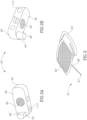
- FIGs. 1A and 1B illustrating a handgun safety device according to the disclosure, generally designated 20 , comprising a safety element 22 articulated to a first end 24 of a cord 28 , with a second end 30 of the cord 28 articulated to an attaching member 32 , configured for attaching to an article worn by a user as will be described herein after.
- the safety element 22 comprises a body portion 40 with a firing interrupting element 44 projecting therefrom, whereby the safety element 22 assumes a generally L-like shape with the firing interrupting element 44 constituting a short arm and the body portion 40 constituting the long arm.
- the size and shape of the safety element 22 and likewise the parameters of the firing interrupting element 44 can be adapted so as to match different handguns, i.e. to conform with the shape and firing mechanism of the weapon concerned.
- the safety element 22 is configured for use in conjunction with a striker-type firing pistol, and more specifically with a Glock TM 19 pistol ( 50 in Figs. 7 ).
- the body portion 40 is configured with a flat bottom face 46 suited for resting flush over the slide 52 of the handgun 50 , as will be discussed hereinafter in greater detail.
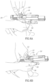
- the shape and size of the firing interrupting element 44 is such so as to partially fit within a cutout 54 formed at a rear side of an ejection port 56 of the slide of the handgun 50 , such that when mounted, face 48 of the firing interrupting element 44 bares flush over a breach face 58 of the handgun ( Figs. 4 and 7B ).
- the safety element 22 is further configured with an attachment arrangement, namely a magnet 60 , for magnetically attracting/attaching the safety element 22 and securing it in position, however readily and easily detachable.
- an attachment arrangement namely a magnet 60
- the attachment arrangement can be a hook and pile couple or other attachment means, however readily and easily detachable.
- the cord 28 is a reinforced rubber coated cord (similar to a pistol safety lanyard with coiled bungee portion), with a coiled portion 64 imparting it elastic properties and spontaneous contraction/retraction so that it has a full length (e.g. Fig. 9E) and a retracted/contracted length.
- the full length of the cord is about 24cm. and the contracted length is about 10cm.
- the cord 28 can be a regular cord, i.e. devoid of any contraction arrangement, or it can be fully coiled so as to increase the ration between the full length and the retracted/contracted length, or it can be associated with a retraction mechanism 61 as illustrated by way of example in Fig. 3 .
- the retraction mechanism 61 is of generally known structure and comprises a housing 62 fitted with a belt mount 63 (i.e. attaching member, configured for attaching to an article worn by a user, so as to constitute said second end of the cord).
- the attaching member can be a buckle, a clip, a band, a snap fastener, a hook and pile fitting, an elastic band, etc.
- the attaching member 32 is a flexible belt loop with a hook and pile fastener 33 configured for attaching to a variety of articles worn by a user, such as a holster (waist, drop leg/ thigh, etc.), a belt, a pants buckle, suspenders, a bag/pouch/purse, and the like.
- the attaching member can be configured as a buckle, a clip, a band, a snap fastener, a hook and pile fitting, an elastic band, etc., facilitating easy attaching and removal thereof.
- the firing interrupting element 44 when the safety element 22 is applied to the handgun (different examples illustrated hereinafter), the firing interrupting element 44 is disposed at an interrupting positon, namely between the rear face 69 of a duty cartridge 70 ( Fig. 4 ) received in the chamber 72 and the functional firing element (i.e. firing/striker pin or breach face 58 ), it obstructs a firing mechanism of the handgun, so that a round cannot be fired even at the event that the trigger is pulled.
- the functional firing element i.e. firing/striker pin or breach face 58
- the firing interrupting element 44 constitutes an obstruction, thereby preventing complete locking of the handgun, whereby incomplete locking displacement of a slide of the handgun breaks contact between the trigger assembly and the striker assembly, i.e. preventing the breach from locking and preventing firing the handgun even at the event that the trigger is pulled.
- Fig. 4 Whilst the example of Fig. 4 refers to a striker-type pistol 50 , in Fig. 5 there is illustrated a hammer-type pistol generally designated 76 wherein the safety element 90 (cord partially illustrated in dashed lines for sake of clarity) is similar to the safety element 22 of the previous example, however with the firing interrupting element 92 extending longer, such that when applied over the pistol 76 , it not only prevents complete locking of the firing mechanism, but rather it also extends in the line of operation of firing pin 93 , behind the rear face 96 of the duty cartridge 98. Thus, even at the event of pulling the trigger, the pistol 76 will not fire, as long as the safety element 90 is at the obstructing position.
- the safety element 90 cord partially illustrated in dashed lines for sake of clarity
- a method using the handgun safety device comprises the steps of:
- a user can cock the slide until it becomes arrested by the slide stop, as known in the art.
- a magazine can be introduced into the pistol before or after cocking the handgun.
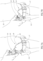
- the handgun 50 is safely introduced into the holster 103 as illustrated in Figs. 8A and 8B , seeing that the safety element 22 remains in place at its interfering positon secured by the magnetic attracting force and slightly being clamped between the breech face and the rear face of the cartridge).
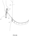
- the firearm 50 is now cocked, with a live round of ammunition in the barrel chamber, and all that it takes for discharging a round is drawing the handgun from the holster 103 as illustrated in Figs. 8A to 81 , illustrated consecutive steps of drawing and firing a round.
- Fig. 8A the handgun is gripped by the user and is then pulled out of the holster ( Fig. 8B ), whilst the cord 28 is not yet at its full length position, i.e. is still loos.
- the handgun 50 reaches an angle ⁇ ° of between about 10° to 55° (measured with respect to an imaginary vertical line), with the cord 28 reaching its predetermined full length ( Fig.
- the handgun safety device can eliminate, or substantially reduce the self-accidents (in particular those caused by users at a fast draw procedure, often occurring when the handgun is pointed below the safe zone , i.e. as in the position of Figs. 8B , 8C ).
- the effective safe zone can be configured and altered depending on several parameters such as the length of the cord, elasticity and retraction force of the cord, strength of the attachment arrangement (e.g. magnetic attraction), location of the attaching member to the user (namely attached to a holster or to a belt at a location forward of the holster), etc. these parameters can be controlled and adjusted to comply with physiological parameters of the individual (the user) and safety requirements.
- the safety element 22 can be attached to the first end of the cord at different configurations.
- the first end 24 of the cord 28 is secured to the housing (body portion 40 ) of the safety element 22 through an aperture 113 extending at an angle with respect to a longitudinal axis of the body portion 40 , whereby it has a specific Left/Right orientation, suited for use by lefthand or righthand users, as may be the case.
- the safety element 22 is configured with indicia (letter R engraved), indicating it is configured for used by a right hand user.
- the body is ready made for either Left/Right cord articulation.
- the body portion of the safety element can be colored at different colors, providing visible indicia e.g. at a training arena. For example, bright colors can indicate that the device is in use with a handgun loaded with live ammunition, etc.
- the body portion of the safety element can comprise a light emitting element, for providing different indications, e.g. the positioning of the device over the handgun, loaded handgun, etc.
Landscapes
- Engineering & Computer Science (AREA)
- General Engineering & Computer Science (AREA)
- Aiming, Guidance, Guns With A Light Source, Armor, Camouflage, And Targets (AREA)
- Emergency Lowering Means (AREA)
Claims (13)
- Handfeuerwaffen-Sicherheitsvorrichtung (20), umfassend:ein Sicherheitselement (22, 90) mit einem Abfeuerungsunterbrechungselement (44, 92), das so konfiguriert ist, dass es zwischen einer Stirnfläche (69, 96) einer Einsatzpatrone (70, 98) und einem vorderen Ende eines funktionalen Abfeuerungselements (58, 93) hervorsteht;eine Schnur (28) mit einer vollen Länge zwischen einem ersten Ende (24) und einem zweiten Ende (30) davon, wobei das Sicherheitselement an dem ersten Ende befestigt ist, das zweite Ende zum Befestigen an einem von einem Benutzer getragenen Gegenstand konfiguriert ist; dadurch gekennzeichnet, dass die Handfeuerwaffen-Sicherheitsvorrichtung (20) ferner einen Schnuraufrollmechanismus (61) umfasst, wobei die Schnur (28) mit dem Schnuraufrollmechanismus (61) verbunden ist.
- Handfeuerwaffen-Sicherheitsvorrichtung (20) nach Anspruch 1, wobei das Abfeuerungsunterbrechungselement, solange es sich in einer Unterbrechungsposition zwischen der Stirnfläche der Einsatzpatrone und dem funktionalen Abfeuerungselement befindet, einen Abfeuerungsmechanismus der Handfeuerwaffe (50, 76) blockiert, sodass kein Schuss abgefeuert werden kann, selbst wenn ein Abzug vom Benutzer betätigt wird.
- Handfeuerwaffen-Sicherheitsvorrichtung (20) nach Anspruch 1, wobei das zweite Ende der Schnur (28) mit einem festen oder einem abnehmbaren Befestigungselement (32) zum festen oder abnehmbaren Befestigen an dem von einem Benutzer getragenen Gegenstand konfiguriert ist.
- Handfeuerwaffen-Sicherheitsvorrichtung (20) nach Anspruch 1, wobei die Schnur (28) so konfiguriert ist, dass sie die volle Länge erreicht, wenn die Handfeuerwaffe gezogen wird und einen Winkel zwischen etwa 15 und 55 Grad einnimmt, gemessen in Bezug auf eine imaginäre vertikale Linie.
- Handfeuerwaffen-Sicherheitsvorrichtung (20) nach Anspruch 1, wobei die Gesamtlänge der Schnur zwischen etwa 20 und 60 cm beträgt.
- Handfeuerwaffen-Sicherheitsvorrichtung (20) nach Anspruch 1, wobei die Schnur (28) an einer Stelle koaxial zur Längsachse des Sicherheitselements angelenkt ist.
- Handfeuerwaffen-Sicherheitsvorrichtung (20) nach Anspruch 1, wobei die Schnur (28) an einer Stelle an das Sicherheitselement angelenkt ist, die von dessen Längsachse versetzt ist.
- Handfeuerwaffen-Sicherheitsvorrichtung (20) nach Anspruch 1, wobei das Sicherheitselement einen L-ähnlichen Querschnitt aufweist, wobei ein langes Armsegment so konfiguriert ist, dass es von außen auf einem Teil der Handfeuerwaffe aufliegt, und ein kurzes Armsegment das Abfeuerungsunterbrechungselement ist.
- Handfeuerwaffen-Sicherheitsvorrichtung (20) nach Anspruch 1, wobei die Länge der Schnur (28) zur Anpassung an verschiedene vom Benutzer getragene Gegenstände und an physiologische Parameter eines Benutzers eingestellt ist.
- Handfeuerwaffen-Sicherheitsvorrichtung (20) nach Anspruch 1, wobei das Sicherheitselement ferner eine Befestigungsanordnung zum Befestigen an der Handfeuerwaffe umfasst, die jedoch leicht abnehmbar ist.
- Handfeuerwaffen-Sicherheitsvorrichtung (20) nach Anspruch 1, wobei die Befestigungsanordnung ein Magnet (60) ist.
- Verfahren zum Gebrauch einer Handfeuerwaffe, gekennzeichnet durch die folgenden Schritte:(a) Erhalten einer Sicherheitsvorrichtung für Handfeuerwaffen (20), die Folgendes umfasst:ein Sicherheitselement (22, 90) mit einem Abfeuerungsunterbrechungselement (44, 92), das so konfiguriert ist, dass es zwischen einer Stirnfläche (69, 96) einer Einsatzpatrone (70, 98) und einem vorderen Ende eines funktionalen Abfeuerungselements (58, 93) hervorsteht,eine Schnur (28), die sich über die gesamte Länge zwischen einem ersten Ende (24) und einem zweiten Ende (30) erstreckt, wobei das Sicherheitselement am ersten Ende befestigt ist und das zweite Ende so gestaltet ist, dass es an einem von einem Benutzer getragenen Gegenstand befestigt werden kann;einen Schnuraufrollmechanismus (61), wobei die Schnur (28) mit dem Schnuraufrollmechanismus (61) verbunden ist;(b) Befestigen des zweiten Endes an einem vom Benutzer getragenen Gegenstand;(c) vor oder nach (b) zumindest teilweises Spannen der Handfeuerwaffe (50, 76), sodass ein Zwischenraum zwischen der Stirnfläche einer Einsatzpatrone und einem vorderen Ende eines funktionellen Abfeuerungselements entsteht;(d) Platzieren des Sicherheitselements mit dem Abfeuerungsunterbrechungselement in einer Unterbrechungsposition; und(e) das Freigeben der Handfeuerwaffe aus der zumindest teilweise gespannten Stellung;
wobei das Ziehen der Handfeuerwaffe, wenn sich das Sicherheitselement mit dem Abfeuerungsunterbrechungselement in einer Unterbrechungsposition befindet und das zweite Ende an dem vom Benutzer getragenen Gegenstand befestigt ist, dazu führt, dass sich die Schnur im Wesentlichen auf ihre volle Länge ausdehnt, wobei eine weitere Bewegung dazu führt, dass sich das Sicherheitselement von der Handfeuerwaffe löst, wodurch ein vollständiger Kontakt und eine vollständige Verriegelung des Abfeuerungsmechanismus der Handfeuerwaffe ermöglicht wird, sodass das Ziehen eines Abzugs der Handfeuerwaffe zum Abfeuern eines Schusses führt. - Verfahren nach Anspruch 12, bei dem das zumindest teilweise Spannen der Handfeuerwaffe dadurch erleichtert werden kann, dass ein Schlitten der Handfeuerwaffe gespannt wird, bis er durch einen Schlittenanschlag arretiert wird.
Applications Claiming Priority (2)
| Application Number | Priority Date | Filing Date | Title |
|---|---|---|---|
| IL256577A IL256577B (en) | 2017-12-25 | 2017-12-25 | Security mechanism for guns |
| PCT/IL2018/051238 WO2019130291A1 (en) | 2017-12-25 | 2018-11-18 | Handgun safety device and method |
Publications (4)
| Publication Number | Publication Date |
|---|---|
| EP3732429A1 EP3732429A1 (de) | 2020-11-04 |
| EP3732429A4 EP3732429A4 (de) | 2021-10-06 |
| EP3732429B1 true EP3732429B1 (de) | 2024-01-03 |
| EP3732429C0 EP3732429C0 (de) | 2024-01-03 |
Family
ID=61198568
Family Applications (1)
| Application Number | Title | Priority Date | Filing Date |
|---|---|---|---|
| EP18897503.1A Active EP3732429B1 (de) | 2017-12-25 | 2018-11-18 | Sicherheitsvorrichtung und -verfahren für handfeuerwaffen |
Country Status (5)
| Country | Link |
|---|---|
| US (2) | US11029112B2 (de) |
| EP (1) | EP3732429B1 (de) |
| ES (1) | ES2976193T3 (de) |
| IL (1) | IL256577B (de) |
| WO (1) | WO2019130291A1 (de) |
Families Citing this family (2)
| Publication number | Priority date | Publication date | Assignee | Title |
|---|---|---|---|---|
| US11435154B2 (en) * | 2020-06-22 | 2022-09-06 | Dylan S. Ervin | Removable firearm chamber-obstruction mechanism and methods thereof |
| US11493295B1 (en) | 2021-07-08 | 2022-11-08 | Charles L. Broadnax | Tamper-actuated fluid release firearm interlock |
Family Cites Families (28)
| Publication number | Priority date | Publication date | Assignee | Title |
|---|---|---|---|---|
| US2997802A (en) * | 1958-11-26 | 1961-08-29 | Lewis C Robbins | Chamber plugging device for firearms |
| US3018576A (en) * | 1961-01-04 | 1962-01-30 | William H Riechers | Locking safety device for firearms |
| US3605311A (en) * | 1969-01-22 | 1971-09-20 | Robert Hermann | Removable firearm lock insertable in the firearm ejection port |
| US4054002A (en) * | 1976-01-02 | 1977-10-18 | Latona Jr Carmen J | Desiccating device for firearm |
| US4084340A (en) * | 1976-08-30 | 1978-04-18 | Gilbert Galde Scudder | Gun bore rust inhibiting method and apparatus |
| US4412397A (en) | 1982-03-19 | 1983-11-01 | Bayn William H | Firearm safety apparatus and method of using same |
| US4835894A (en) | 1988-06-07 | 1989-06-06 | Jack Libassi | Safety device for automatic firearms |
| US4833811A (en) * | 1988-07-07 | 1989-05-30 | Earl Wilkinson | Safety for pistols |
| US4896447A (en) * | 1988-12-30 | 1990-01-30 | Badoni Paul A | Safety maintenance implement for firearms |
| US5097613A (en) * | 1989-07-06 | 1992-03-24 | Miller Gary L | Safety plug for the firing chamber of a weapon |
| US4965952A (en) * | 1989-07-06 | 1990-10-30 | Miller Gary L | Safety plug for the firing chamber of a weapon |
| US5067613A (en) | 1991-05-13 | 1991-11-26 | Bryan William T | Gable top carton with interiorly stored reclosable spout |
| US5410832A (en) * | 1994-02-18 | 1995-05-02 | Barnhart; Terry L. | Weapon chamber safety plug kit |
| US5419069A (en) * | 1994-07-14 | 1995-05-30 | Mag-Lok, Inc. | Firearm locking mechanism |
| US5669252A (en) * | 1995-04-13 | 1997-09-23 | Bentley; James K. | Combination shotgun lock and ejection port cover assembly |
| US6250008B1 (en) * | 1999-09-10 | 2001-06-26 | Safe Tech, Inc. | Firearm safety plug |
| US6470615B1 (en) * | 2000-10-30 | 2002-10-29 | William H. Peterken | Visible firearm safety and dry-fire device |
| US6591532B1 (en) * | 2001-05-14 | 2003-07-15 | Product Source Llc | Gun ejection port lock |
| US6785994B2 (en) * | 2002-06-17 | 2004-09-07 | Ned F. Christiansen | Spring-loaded firearm safety indicator |
| US20140325889A1 (en) * | 2010-01-11 | 2014-11-06 | Frank J. Michal | Adhesive and bolt-on type gun grip, gun equipment and accessory systems |
| USD631123S1 (en) * | 2010-05-26 | 2011-01-18 | Patrick William Byers | Chamber block |
| US9267759B2 (en) * | 2012-01-12 | 2016-02-23 | Walter Speroni | Tactical accessory mount, aiming device, and method for securing a tactical accessory to a pistol |
| USD701282S1 (en) * | 2012-10-25 | 2014-03-18 | II Richard Timothy Ferguson | Small caliber firearm safety plug |
| US8850738B2 (en) * | 2013-02-22 | 2014-10-07 | Safe Tech, Inc. | Combination safety round and multi-tool |
| IL247226A0 (en) * | 2015-08-11 | 2016-09-29 | Aziz Meir | Safety device for firearms |
| USD779016S1 (en) * | 2015-12-16 | 2017-02-14 | Joseph M. Rumpke | Muzzle plug |
| US9810499B1 (en) * | 2016-09-02 | 2017-11-07 | Safe Tech, Inc. | Safety round |
| USD827761S1 (en) * | 2017-08-17 | 2018-09-04 | Joseph M Rumpke | Chamber flag |
-
2017
- 2017-12-25 IL IL256577A patent/IL256577B/en active IP Right Grant
-
2018
- 2018-11-18 WO PCT/IL2018/051238 patent/WO2019130291A1/en not_active Ceased
- 2018-11-18 ES ES18897503T patent/ES2976193T3/es active Active
- 2018-11-18 EP EP18897503.1A patent/EP3732429B1/de active Active
- 2018-11-18 US US16/957,476 patent/US11029112B2/en active Active
-
2021
- 2021-05-06 US US17/313,900 patent/US11519684B2/en active Active
Also Published As
| Publication number | Publication date |
|---|---|
| WO2019130291A1 (en) | 2019-07-04 |
| EP3732429C0 (de) | 2024-01-03 |
| US20210071973A1 (en) | 2021-03-11 |
| IL256577A (en) | 2018-01-31 |
| IL256577B (en) | 2021-06-30 |
| US20220099396A1 (en) | 2022-03-31 |
| ES2976193T3 (es) | 2024-07-26 |
| EP3732429A1 (de) | 2020-11-04 |
| EP3732429A4 (de) | 2021-10-06 |
| US11519684B2 (en) | 2022-12-06 |
| US11029112B2 (en) | 2021-06-08 |
Similar Documents
| Publication | Publication Date | Title |
|---|---|---|
| RU2150648C1 (ru) | Устройство для предохранения и перевода в боевое положение портативного огнестрельного оружия | |
| RU2445569C2 (ru) | Кобура с возможностью блокировки и с многоразмерным регулируемым поясным креплением | |
| US9841250B1 (en) | Firearm covers | |
| US9618298B2 (en) | Methods and devices relating to firearms | |
| US6829855B2 (en) | Ambidextrous reserve magazine holder for a firearm | |
| US8690032B2 (en) | Holster | |
| US4298150A (en) | Pistol charging holster | |
| US11874087B1 (en) | Sling attachment device | |
| US20180087858A1 (en) | Trigger mechanism for a firearm | |
| US20070163164A1 (en) | Holster for carrying or wearing smallarms | |
| US10371486B2 (en) | Firearm accessory mount | |
| US11519684B2 (en) | Handgun safety device and method | |
| US20080272162A1 (en) | Holster | |
| US20140237877A1 (en) | Combination safety round and multi-tool | |
| US20150233663A1 (en) | Firearm attachment apparatus for dry fire training | |
| US9927218B1 (en) | Firearm magazine holder | |
| US4989358A (en) | Hand gun brace for converting a side handle baton to hand gun stock | |
| US11656047B1 (en) | Chamber flag | |
| WO2018023076A1 (en) | Dual firearm gunstock holstering | |
| CN212620362U (zh) | 一种枪机架 | |
| KR101789432B1 (ko) | 3중 안전장치를 구비한 리볼버용 권총 홀스터 | |
| EP0840878B1 (de) | Handwaffetragevorrichtung | |
| US20260133010A1 (en) | Wearable Device for One-Handed Reloading of a Firearm | |
| CN205860870U (zh) | 一种双重保险防抢枪套 | |
| US20180010873A1 (en) | Hammer with rotatable spur |
Legal Events
| Date | Code | Title | Description |
|---|---|---|---|
| STAA | Information on the status of an ep patent application or granted ep patent |
Free format text: STATUS: THE INTERNATIONAL PUBLICATION HAS BEEN MADE |
|
| PUAI | Public reference made under article 153(3) epc to a published international application that has entered the european phase |
Free format text: ORIGINAL CODE: 0009012 |
|
| STAA | Information on the status of an ep patent application or granted ep patent |
Free format text: STATUS: REQUEST FOR EXAMINATION WAS MADE |
|
| 17P | Request for examination filed |
Effective date: 20200720 |
|
| AK | Designated contracting states |
Kind code of ref document: A1 Designated state(s): AL AT BE BG CH CY CZ DE DK EE ES FI FR GB GR HR HU IE IS IT LI LT LU LV MC MK MT NL NO PL PT RO RS SE SI SK SM TR |
|
| AX | Request for extension of the european patent |
Extension state: BA ME |
|
| DAV | Request for validation of the european patent (deleted) | ||
| DAX | Request for extension of the european patent (deleted) | ||
| A4 | Supplementary search report drawn up and despatched |
Effective date: 20210903 |
|
| RIC1 | Information provided on ipc code assigned before grant |
Ipc: F41A 17/74 20060101ALI20210830BHEP Ipc: F41A 17/24 20060101AFI20210830BHEP |
|
| RIN1 | Information on inventor provided before grant (corrected) |
Inventor name: WEISS, AMIR |
|
| STAA | Information on the status of an ep patent application or granted ep patent |
Free format text: STATUS: EXAMINATION IS IN PROGRESS |
|
| 17Q | First examination report despatched |
Effective date: 20220818 |
|
| GRAP | Despatch of communication of intention to grant a patent |
Free format text: ORIGINAL CODE: EPIDOSNIGR1 |
|
| STAA | Information on the status of an ep patent application or granted ep patent |
Free format text: STATUS: GRANT OF PATENT IS INTENDED |
|
| RAP3 | Party data changed (applicant data changed or rights of an application transferred) |
Owner name: STATE OF ISRAEL, PRIME MINISTER OFFICE |
|
| INTG | Intention to grant announced |
Effective date: 20230714 |
|
| GRAS | Grant fee paid |
Free format text: ORIGINAL CODE: EPIDOSNIGR3 |
|
| GRAA | (expected) grant |
Free format text: ORIGINAL CODE: 0009210 |
|
| STAA | Information on the status of an ep patent application or granted ep patent |
Free format text: STATUS: THE PATENT HAS BEEN GRANTED |
|
| AK | Designated contracting states |
Kind code of ref document: B1 Designated state(s): AL AT BE BG CH CY CZ DE DK EE ES FI FR GB GR HR HU IE IS IT LI LT LU LV MC MK MT NL NO PL PT RO RS SE SI SK SM TR |
|
| REG | Reference to a national code |
Ref country code: GB Ref legal event code: FG4D |
|
| REG | Reference to a national code |
Ref country code: DE Ref legal event code: R096 Ref document number: 602018063804 Country of ref document: DE |
|
| REG | Reference to a national code |
Ref country code: CH Ref legal event code: EP |
|
| REG | Reference to a national code |
Ref country code: IE Ref legal event code: FG4D |
|
| U01 | Request for unitary effect filed |
Effective date: 20240130 |
|
| U07 | Unitary effect registered |
Designated state(s): AT BE BG DE DK EE FI FR IT LT LU LV MT NL PT SE SI Effective date: 20240208 |
|
| PG25 | Lapsed in a contracting state [announced via postgrant information from national office to epo] |
Ref country code: IS Free format text: LAPSE BECAUSE OF FAILURE TO SUBMIT A TRANSLATION OF THE DESCRIPTION OR TO PAY THE FEE WITHIN THE PRESCRIBED TIME-LIMIT Effective date: 20240503 |
|
| PG25 | Lapsed in a contracting state [announced via postgrant information from national office to epo] |
Ref country code: GR Free format text: LAPSE BECAUSE OF FAILURE TO SUBMIT A TRANSLATION OF THE DESCRIPTION OR TO PAY THE FEE WITHIN THE PRESCRIBED TIME-LIMIT Effective date: 20240404 |
|
| PG25 | Lapsed in a contracting state [announced via postgrant information from national office to epo] |
Ref country code: HR Free format text: LAPSE BECAUSE OF FAILURE TO SUBMIT A TRANSLATION OF THE DESCRIPTION OR TO PAY THE FEE WITHIN THE PRESCRIBED TIME-LIMIT Effective date: 20240103 Ref country code: RS Free format text: LAPSE BECAUSE OF FAILURE TO SUBMIT A TRANSLATION OF THE DESCRIPTION OR TO PAY THE FEE WITHIN THE PRESCRIBED TIME-LIMIT Effective date: 20240403 |
|
| PG25 | Lapsed in a contracting state [announced via postgrant information from national office to epo] |
Ref country code: CZ Free format text: LAPSE BECAUSE OF FAILURE TO SUBMIT A TRANSLATION OF THE DESCRIPTION OR TO PAY THE FEE WITHIN THE PRESCRIBED TIME-LIMIT Effective date: 20240103 |
|
| REG | Reference to a national code |
Ref country code: ES Ref legal event code: FG2A Ref document number: 2976193 Country of ref document: ES Kind code of ref document: T3 Effective date: 20240726 |
|
| PG25 | Lapsed in a contracting state [announced via postgrant information from national office to epo] |
Ref country code: RS Free format text: LAPSE BECAUSE OF FAILURE TO SUBMIT A TRANSLATION OF THE DESCRIPTION OR TO PAY THE FEE WITHIN THE PRESCRIBED TIME-LIMIT Effective date: 20240403 Ref country code: NO Free format text: LAPSE BECAUSE OF FAILURE TO SUBMIT A TRANSLATION OF THE DESCRIPTION OR TO PAY THE FEE WITHIN THE PRESCRIBED TIME-LIMIT Effective date: 20240403 Ref country code: IS Free format text: LAPSE BECAUSE OF FAILURE TO SUBMIT A TRANSLATION OF THE DESCRIPTION OR TO PAY THE FEE WITHIN THE PRESCRIBED TIME-LIMIT Effective date: 20240503 Ref country code: HR Free format text: LAPSE BECAUSE OF FAILURE TO SUBMIT A TRANSLATION OF THE DESCRIPTION OR TO PAY THE FEE WITHIN THE PRESCRIBED TIME-LIMIT Effective date: 20240103 Ref country code: GR Free format text: LAPSE BECAUSE OF FAILURE TO SUBMIT A TRANSLATION OF THE DESCRIPTION OR TO PAY THE FEE WITHIN THE PRESCRIBED TIME-LIMIT Effective date: 20240404 Ref country code: CZ Free format text: LAPSE BECAUSE OF FAILURE TO SUBMIT A TRANSLATION OF THE DESCRIPTION OR TO PAY THE FEE WITHIN THE PRESCRIBED TIME-LIMIT Effective date: 20240103 |
|
| PG25 | Lapsed in a contracting state [announced via postgrant information from national office to epo] |
Ref country code: PL Free format text: LAPSE BECAUSE OF FAILURE TO SUBMIT A TRANSLATION OF THE DESCRIPTION OR TO PAY THE FEE WITHIN THE PRESCRIBED TIME-LIMIT Effective date: 20240103 |
|
| PG25 | Lapsed in a contracting state [announced via postgrant information from national office to epo] |
Ref country code: PL Free format text: LAPSE BECAUSE OF FAILURE TO SUBMIT A TRANSLATION OF THE DESCRIPTION OR TO PAY THE FEE WITHIN THE PRESCRIBED TIME-LIMIT Effective date: 20240103 |
|
| REG | Reference to a national code |
Ref country code: DE Ref legal event code: R097 Ref document number: 602018063804 Country of ref document: DE |
|
| PG25 | Lapsed in a contracting state [announced via postgrant information from national office to epo] |
Ref country code: SM Free format text: LAPSE BECAUSE OF FAILURE TO SUBMIT A TRANSLATION OF THE DESCRIPTION OR TO PAY THE FEE WITHIN THE PRESCRIBED TIME-LIMIT Effective date: 20240103 |
|
| PG25 | Lapsed in a contracting state [announced via postgrant information from national office to epo] |
Ref country code: SK Free format text: LAPSE BECAUSE OF FAILURE TO SUBMIT A TRANSLATION OF THE DESCRIPTION OR TO PAY THE FEE WITHIN THE PRESCRIBED TIME-LIMIT Effective date: 20240103 |
|
| PG25 | Lapsed in a contracting state [announced via postgrant information from national office to epo] |
Ref country code: SM Free format text: LAPSE BECAUSE OF FAILURE TO SUBMIT A TRANSLATION OF THE DESCRIPTION OR TO PAY THE FEE WITHIN THE PRESCRIBED TIME-LIMIT Effective date: 20240103 Ref country code: SK Free format text: LAPSE BECAUSE OF FAILURE TO SUBMIT A TRANSLATION OF THE DESCRIPTION OR TO PAY THE FEE WITHIN THE PRESCRIBED TIME-LIMIT Effective date: 20240103 Ref country code: RO Free format text: LAPSE BECAUSE OF FAILURE TO SUBMIT A TRANSLATION OF THE DESCRIPTION OR TO PAY THE FEE WITHIN THE PRESCRIBED TIME-LIMIT Effective date: 20240103 |
|
| PLBE | No opposition filed within time limit |
Free format text: ORIGINAL CODE: 0009261 |
|
| STAA | Information on the status of an ep patent application or granted ep patent |
Free format text: STATUS: NO OPPOSITION FILED WITHIN TIME LIMIT |
|
| 26N | No opposition filed |
Effective date: 20241007 |
|
| U20 | Renewal fee for the european patent with unitary effect paid |
Year of fee payment: 7 Effective date: 20241127 |
|
| REG | Reference to a national code |
Ref country code: CH Ref legal event code: PL |
|
| PG25 | Lapsed in a contracting state [announced via postgrant information from national office to epo] |
Ref country code: MC Free format text: LAPSE BECAUSE OF FAILURE TO SUBMIT A TRANSLATION OF THE DESCRIPTION OR TO PAY THE FEE WITHIN THE PRESCRIBED TIME-LIMIT Effective date: 20240103 |
|
| REG | Reference to a national code |
Ref country code: CH Ref legal event code: PL |
|
| PG25 | Lapsed in a contracting state [announced via postgrant information from national office to epo] |
Ref country code: CH Free format text: LAPSE BECAUSE OF NON-PAYMENT OF DUE FEES Effective date: 20241130 |
|
| PG25 | Lapsed in a contracting state [announced via postgrant information from national office to epo] |
Ref country code: IE Free format text: LAPSE BECAUSE OF NON-PAYMENT OF DUE FEES Effective date: 20241118 |
|
| U20 | Renewal fee for the european patent with unitary effect paid |
Year of fee payment: 8 Effective date: 20251128 |
|
| PGFP | Annual fee paid to national office [announced via postgrant information from national office to epo] |
Ref country code: GB Payment date: 20251128 Year of fee payment: 8 |
|
| PGFP | Annual fee paid to national office [announced via postgrant information from national office to epo] |
Ref country code: ES Payment date: 20251209 Year of fee payment: 8 |
|
| PG25 | Lapsed in a contracting state [announced via postgrant information from national office to epo] |
Ref country code: HU Free format text: LAPSE BECAUSE OF FAILURE TO SUBMIT A TRANSLATION OF THE DESCRIPTION OR TO PAY THE FEE WITHIN THE PRESCRIBED TIME-LIMIT; INVALID AB INITIO Effective date: 20181118 |
|
| PG25 | Lapsed in a contracting state [announced via postgrant information from national office to epo] |
Ref country code: CY Free format text: LAPSE BECAUSE OF FAILURE TO SUBMIT A TRANSLATION OF THE DESCRIPTION OR TO PAY THE FEE WITHIN THE PRESCRIBED TIME-LIMIT; INVALID AB INITIO Effective date: 20181118 |