EP3731721B1 - A dishwasher comprising a micro-filter - Google Patents
A dishwasher comprising a micro-filter Download PDFInfo
- Publication number
- EP3731721B1 EP3731721B1 EP18894309.6A EP18894309A EP3731721B1 EP 3731721 B1 EP3731721 B1 EP 3731721B1 EP 18894309 A EP18894309 A EP 18894309A EP 3731721 B1 EP3731721 B1 EP 3731721B1
- Authority
- EP
- European Patent Office
- Prior art keywords
- filter
- air
- line
- dishwasher
- fan
- Prior art date
- Legal status (The legal status is an assumption and is not a legal conclusion. Google has not performed a legal analysis and makes no representation as to the accuracy of the status listed.)
- Active
Links
Images


Classifications
-
- A—HUMAN NECESSITIES
- A47—FURNITURE; DOMESTIC ARTICLES OR APPLIANCES; COFFEE MILLS; SPICE MILLS; SUCTION CLEANERS IN GENERAL
- A47L—DOMESTIC WASHING OR CLEANING; SUCTION CLEANERS IN GENERAL
- A47L15/00—Washing or rinsing machines for crockery or tableware
- A47L15/42—Details
- A47L15/4202—Water filter means or strainers
- A47L15/4208—Arrangements to prevent clogging of the filters, e.g. self-cleaning
-
- A—HUMAN NECESSITIES
- A47—FURNITURE; DOMESTIC ARTICLES OR APPLIANCES; COFFEE MILLS; SPICE MILLS; SUCTION CLEANERS IN GENERAL
- A47L—DOMESTIC WASHING OR CLEANING; SUCTION CLEANERS IN GENERAL
- A47L15/00—Washing or rinsing machines for crockery or tableware
- A47L15/42—Details
- A47L15/4291—Recovery arrangements, e.g. for the recovery of energy or water
-
- A—HUMAN NECESSITIES
- A47—FURNITURE; DOMESTIC ARTICLES OR APPLIANCES; COFFEE MILLS; SPICE MILLS; SUCTION CLEANERS IN GENERAL
- A47L—DOMESTIC WASHING OR CLEANING; SUCTION CLEANERS IN GENERAL
- A47L15/00—Washing or rinsing machines for crockery or tableware
- A47L15/42—Details
- A47L15/48—Drying arrangements
- A47L15/483—Drying arrangements by using condensers
-
- A—HUMAN NECESSITIES
- A47—FURNITURE; DOMESTIC ARTICLES OR APPLIANCES; COFFEE MILLS; SPICE MILLS; SUCTION CLEANERS IN GENERAL
- A47L—DOMESTIC WASHING OR CLEANING; SUCTION CLEANERS IN GENERAL
- A47L15/00—Washing or rinsing machines for crockery or tableware
- A47L15/42—Details
- A47L15/48—Drying arrangements
- A47L15/486—Blower arrangements
-
- A—HUMAN NECESSITIES
- A47—FURNITURE; DOMESTIC ARTICLES OR APPLIANCES; COFFEE MILLS; SPICE MILLS; SUCTION CLEANERS IN GENERAL
- A47L—DOMESTIC WASHING OR CLEANING; SUCTION CLEANERS IN GENERAL
- A47L2401/00—Automatic detection in controlling methods of washing or rinsing machines for crockery or tableware, e.g. information provided by sensors entered into controlling devices
- A47L2401/14—Water pressure or flow rate
-
- A—HUMAN NECESSITIES
- A47—FURNITURE; DOMESTIC ARTICLES OR APPLIANCES; COFFEE MILLS; SPICE MILLS; SUCTION CLEANERS IN GENERAL
- A47L—DOMESTIC WASHING OR CLEANING; SUCTION CLEANERS IN GENERAL
- A47L2501/00—Output in controlling method of washing or rinsing machines for crockery or tableware, i.e. quantities or components controlled, or actions performed by the controlling device executing the controlling method
- A47L2501/12—Air blowers
Definitions
- the present invention relates to a dishwasher comprising a micro-filter retaining the dirt particles removed from the dishes.
- Dishwashers In dishwashers, using filters inhibiting dirt particles removed from dishes, from being mixed back into washing water cycle, is known. Filters fill over time and eventually get blocked. In this case a user has to clean said filter. Dishwashers are present which take off the burden of cleaning from the users, capable of performing self cleaning of a filter. This operation is generally performed during discharging process by spraying water into the filter by means of a separate line. When cleaning is performed by spraying water outwards from interior of the filter, dirt particles are forced to move outwards of the filter and block the gaps in the braided structure of the filter. Therefore a complete cleaning operation cannot be performed.
- EP2989958 discloses a dishwasher in which filter cleaning is performed by steam provided by a steam generator.
- German patent application no. DE10249130 discloses a dishwasher in which filter cleaning is performed by ultrasonic sound waves.
- United States patent application no. 2012138107 discloses a dishwasher wherein a single pump and filter unit is used for multiple compartments thereof.
- German patent application no. DE102014101260 discloses a dishwasher with a supply system for washing liquid, comprising a first line part through which the liquid flows and an air supply system comprising a second line part through which the air flows.
- the aim of the present invention is to realize a dishwasher in which micro-filter blockage is avoided.
- the dishwasher realized to achieve the aim of the present invention and disclosed in the claims, comprises a blower mechanism having a line extending towards into a chamber provided on the base of the washing space in which the washing and rinsing processes are performed, particularly towards a filter in the chamber, and a control unit enabling air to be blown inwards from outside on the filter by controlling the blower mechanism.
- the dirt particles entering the surface of the filter i.e. into the gaps in between the braided structure, are removed from the surface by blowing air inwards from outside and are collected within the filter which preferably has a cylindrical structure.
- the filter which preferably has a cylindrical structure.
- control unit enables air to be blown on the filter in washing and/or rinsing steps.
- the filter is thus prevented from being blocked during the washing and rinsing processes.
- control unit decides air to be blown on the filter according to the flow rate of the pump executing water circulation.
- the flow rate of the pump decreases when the filter is blocked.
- the control unit enables blowing air on the filter by operating the blower mechanism upon detecting a decrease in the flow rate of the pump.
- the air blown on the filter is provided by means of an air compressor.
- the control unit enables sending air on the filter by activating the air compressor.
- the air blown on the filter is provided by means of a first fan performing in the drying step air circulation between the washing space and the drying duct in which the evaporating water is condensed.
- a first fan performing in the drying step air circulation between the washing space and the drying duct in which the evaporating water is condensed.
- the air blown on the filter is provided by means of a second fan enabling blowing outer environment air on a heat exchanger which is one of the heat pump members used in heating mains water.
- a second fan enabling blowing outer environment air on a heat exchanger which is one of the heat pump members used in heating mains water.
- an external air compressor is not required, avoiding a cost increase to remove the dirt particles on the filter.
- the line conveying the air blown on the filter may be disposed before or after the heat exchanger in air flow direction. Sending into the line all of the air provided by the second fan, can be enabled by means of a flap blocking the air advancing to the heat exchanger.
- the line conveying air is wound on the heat exchanger whose surface is hot. The air in the line is thus heated, avoiding cooling of the washing water.
- the cross-section of the line conveying air narrows down towards the filter. The air is thus accelerated and water is prevented from being introduced into the line.
- a nozzle is provided on the end of the line closer to the filter.
- the nozzle allows passage of only gas, i.e. air and blocks liquid passage. Water is thus prevented from being introduced into the line.
- the nozzle functions as a non-return valve and allows passage only through the line in the direction of the filter. Water passage is also blocked in this embodiment.
- the dirt articles removed from the dishes are prevented from blocking the filter by blowing air on the filter inwards from outside, and the dirt particles are enabled to be easily removed.
- using an external air supply unit is not required by using the fan already used in the drying step or the fan assisting the heat pump in drawing heat from the outer environment, enabling elimination of filter blockage without a cost increase.
- the dishwasher (1) comprises a body (2), a washing space (3) provided in the body (2), in which the washing and rinsing processes are performed, a chamber (4) provided on the base of the washing space (3), a filter (5) provided in the chamber (4), and a pump (6) enabling the water received from the mains into the chamber (4) to be sent to the washing space (3) and thus to be circulated.
- the baskets (17) in which the dishes to be washed are placed, are provided in the washing space (3), as well as the spray arms (18) above or below the baskets (17), enabling conveying the water transmitted by the pump (6) to the dishes. A user places the dishes into the washing space (3).
- the pump (6) draws from within the chamber (4) the water received from the mains, and sends it to the washing space (3).
- the water reaching the dishes in the washing space (3) flows back towards the base of the washing space (3), and is cleaned from dirt by passing though the filter (5) before being collected in the chamber (4).
- the pump (6) draws from the chamber (4) the filtered water and sends it back to the washing space (3), thereby enabling water circulation.
- the water in the chamber (4) and the dirt particles collected on the filter (5) are discharged by means of a discharge pump (not shown in the figures).
- the dishwasher (1) of the invention comprises a blower mechanism (8) having a line (7) extending into the chamber (4), and a control unit (9) enabling sending air by means of the blower mechanism (8), on the filter (5) in the direction from the chamber (4) to the filter (5).
- the line (7) extends into the chamber (4) towards the filter (5).
- the blower mechanism (8) thus blows air on the outer surface of the filter (5) inwards from outside, enabling removal of the dirt particles stuck on the filter (5) surface, towards the center of the filter (5) which generally has a cylindrical structure. By this, the water is prevented from being trapped in the filter (5) due to filter (5) blockage, enabling smooth circulation.
- the air blown through the line (7) by means of the blower mechanism (8) is pressurized enough so as not to allow water to be introduced in to the line (7) due to the chamber (4) being filled with water.
- control unit (9) enables air to be blown on the filter (5) in washing and/or rinsing steps.
- the control unit (9) enables blowing air on the filter (5) in washing and rinsing steps in which the filter (5) is the most likely to be blocked, thereby enabling the washing and rinsing processes to be performed without blockage of the filter (5).
- control unit (9) enables air to be blown on the filter (5) when the flow rate of the pump (6) decreases in washing or rinsing steps.
- the control unit (9) continuously monitors the flow rate of the pump (6). When the filter (5) is blocked by dirt particles stuck thereon, the flow rate of the water pumped by the pump (6) decreases, and the pump (6) begins drawing more power.
- the control unit (9) enables eliminating filter (5) blockage by enabling air to be blown on the outer surface of the filter (5) by means of the blower mechanism (8).
- This embodiment makes it unnecessary to continually blow air on the filter (5), and the control unit (9) activates the blower mechanism (8) only when required upon decreasing of the flow rate of the pump (6) which indicates of filter (5) blockage.
- the blower mechanism (8) comprises an air compressor (10) provided in the body (2), blowing air into the line (7).
- the air compressor (10) blows air while connected to the free end of the line (7).
- the control unit (9) controls the air compressor (10).
- the dishwasher (1) comprises a drying duct (11) provided in the body (2), in which the water evaporated from the washed dishes, is condensed, and a first fan (12) enabling circulation of the air in the drying duct (11), and an end of the line (7) extends to the first fan (12), and the control unit (9) enables blowing air into the line (7) by controlling the first fan (12).
- the control unit (9) controls the first fan (12) and circulates air between the drying duct (11) and the washing space (3), and enables the water evaporated from the dishes to be condensed on the drying duct (11) which has a cold surface.
- an end of the line (7) extends to the vicinity of the first fan (12), and air is blown into the line (7) when the first fan (12) operates.
- the control unit (9) activates the first fan (12) and enables air to be blown into the line (7).
- the dishwasher (1) comprises a heat pump (13) having at least one heat exchanger (14) enabling heating the water received from the mains, and a second fan (15) blowing air on the heat exchanger (14), and an end of the line (7) extends to the second fan (15) and the control unit (9) enables blowing air into the line (7) by controlling the second fan (15).
- the control unit (9) activates the second fan (15) and enables air to be blown into the line (7).
- elements already provided in the dishwasher (1) are used in order to provide air to be blown to clean the filter (5), avoiding an additional cost increase for cleaning the filter (5).
- control unit (9) enables blowing air on the filter (5) when the water heating duration of the heat pump (13) is longer than a predetermined limit duration.
- the amount of water transmitted to the heat pump (13) decreases when the filter (5) is blocked, decreasing the heat transfer amount on the heat exchanger (14) whose surface is hot. This prolongs the heating duration of water to be used in washing.
- the control unit (9) compares the heating duration with a limit duration predetermined preferably according to each washing program by the producer and when the heating duration is longer than the limit duration the control unit determines that the filter (5) is blocked and enables blowing air on the filter (5).
- the control unit (9) may enable blowing air on the filter (5) by considering only the water heating duration of the heat pump (13), as well as also by checking the flow rate of the pump (6) as in an above-disclosed embodiment, together with this embodiment.
- the control unit (9) can thus fully detect blockage of the filter (5), avoiding excessive energy consumption by enabling air to be blown on the filter (5) only when required.
- the end of the line (7) extends between the heat exchanger (14) and the second fan (15) in air flow direction.
- the air blown by the second fan (15) is sent into the line (7) without passing via the heat exchanger (14), i.e. without the air temperature being decreased or increased.
- the dishwasher (1) comprises a flap (16) having a closed position in which the air flow to the heat exchanger (14) is blocked, and the control unit (9) enables the flap (16) to switch to the closed position when air is to be blown into the line (7). All of the air provided by the second fan (15) is enabled to be sent into the line (7) thanks to this embodiment.
- the end of the line (7) is disposed after the heat exchanger (14) in air flow direction, and the air passed via the heat exchanger (14) is transmitted into the line (7).
- heat is drawn from the outer environment by transferring air from the outer environment on to a heat exchanger (14) which has a cold surface.
- the surface of the heat exchanger (14) is also cold in this embodiment, therefore the temperature of the air blown by the second fan (15) decreases after passing over the heat exchanger (14). Since the end of the line (7) is after the heat exchanger (14), the air with decreased temperature enters the line (7) and is transmitted to the filter (5).
- the filter (5) is warmer than the outer environment because there is hot water in the chamber (4) during the washing and rinsing processes.
- the dirt particles are enabled to be separated/removed from the filter (5) surface also by the effect created by the difference in temperatures in addition to the repulsion effect of air.
- the line (7) winds around the heat exchanger (14) which has a hot surface.
- the temperature of the air blown on the filter (5) is equal to the outer environment temperature or is lower than the outer environment temperature as disclosed in the above embodiment. This causes the temperature of the washing water in the chamber (4) to decrease up to a certain extent.
- the air in the line (7) is enabled to be heated, preventing the washing water temperature from decreasing.
- the cross-section of the line (7) narrows down towards the filter (5).
- the velocity and the pressure of the air blown on the filter (5) is thus increased, thereby avoiding introduction of water into the line (7).
- the blower mechanism (8) comprises a nozzle (not shown in the figures) provided on the end of the line (7), which does not allow liquid to pass therethrough.
- the nozzle only allows passage of air and blocks liquid passage. Thus, water may not pass into the line (7) even when the air blown on the filter (5) is not sufficiently pressurized.
- the blower mechanism (8) comprises a nozzle (not shown in the figures) provided on the end of the line (7), not allowing passage through the filter (5) in the direction of the line (7).
- the nozzle functions as a non-return valve and allows passage only through the line (7) in the direction of the filter (5). Water is thus prevented from being introduced into the line (7).
- the nozzle may be adapted to allow only air passage like the above embodiment, as well as being adapted to allow passage in one direction as disclosed in this embodiment.
- filter (5) blockage is avoided particularly during the washing and rinsing processes, preventing the overall washing duration from being prolonged.
- straining of the pump (6) and the other members are averted, enabling the useful lifetime of the dishwasher (1) to be prolonged.
Landscapes
- Washing And Drying Of Tableware (AREA)
Description
- The present invention relates to a dishwasher comprising a micro-filter retaining the dirt particles removed from the dishes.
- In dishwashers, using filters inhibiting dirt particles removed from dishes, from being mixed back into washing water cycle, is known. Filters fill over time and eventually get blocked. In this case a user has to clean said filter. Dishwashers are present which take off the burden of cleaning from the users, capable of performing self cleaning of a filter. This operation is generally performed during discharging process by spraying water into the filter by means of a separate line. When cleaning is performed by spraying water outwards from interior of the filter, dirt particles are forced to move outwards of the filter and block the gaps in the braided structure of the filter. Therefore a complete cleaning operation cannot be performed. In addition, since such cleaning operation is executed during discharging, if the filter is blocked during the washing or rinsing process, no cleaning is performed until the washing process is completed. In this case the washing performance of the dishwasher decreases, the pump enabling water circulation operates more loudly and energy consumption increases.
- State of the art European patent application no.
EP2989958 discloses a dishwasher in which filter cleaning is performed by steam provided by a steam generator. - State of the art German patent application no.
DE10249130 discloses a dishwasher in which filter cleaning is performed by ultrasonic sound waves. - State of the art
international patent application no. WO2009077283 discloses a dishwasher in which filter cleaning is performed by spraying pressurized water by means of an additional circulation line. -
United States patent application no. 2012138107 discloses a dishwasher wherein a single pump and filter unit is used for multiple compartments thereof. - German patent application no.
DE102014101260 discloses a dishwasher with a supply system for washing liquid, comprising a first line part through which the liquid flows and an air supply system comprising a second line part through which the air flows. - The aim of the present invention is to realize a dishwasher in which micro-filter blockage is avoided.
- The dishwasher realized to achieve the aim of the present invention and disclosed in the claims, comprises a blower mechanism having a line extending towards into a chamber provided on the base of the washing space in which the washing and rinsing processes are performed, particularly towards a filter in the chamber, and a control unit enabling air to be blown inwards from outside on the filter by controlling the blower mechanism. The dirt particles entering the surface of the filter, i.e. into the gaps in between the braided structure, are removed from the surface by blowing air inwards from outside and are collected within the filter which preferably has a cylindrical structure. Thus, occurrence of the above-mentioned problems by blockage of the filter are avoided. In addition, by collecting the dirt particles on the center of the filter, all dirt are enabled to be easily and smoothly discharged in the discharging step.
- In an embodiment of the invention, the control unit enables air to be blown on the filter in washing and/or rinsing steps. The filter is thus prevented from being blocked during the washing and rinsing processes.
- In another embodiment of the invention, the control unit decides air to be blown on the filter according to the flow rate of the pump executing water circulation. The flow rate of the pump decreases when the filter is blocked. The control unit enables blowing air on the filter by operating the blower mechanism upon detecting a decrease in the flow rate of the pump.
- In another embodiment of the invention, the air blown on the filter is provided by means of an air compressor. The control unit enables sending air on the filter by activating the air compressor.
- In another embodiment of the invention, the air blown on the filter is provided by means of a first fan performing in the drying step air circulation between the washing space and the drying duct in which the evaporating water is condensed. With this embodiment, an air compressor or a similar member is not needed for providing air to blow on the filter.
- In another embodiment of the invention, the air blown on the filter is provided by means of a second fan enabling blowing outer environment air on a heat exchanger which is one of the heat pump members used in heating mains water. Likewise the above embodiment, an external air compressor is not required, avoiding a cost increase to remove the dirt particles on the filter.
- In other embodiments of the invention, the line conveying the air blown on the filter may be disposed before or after the heat exchanger in air flow direction. Sending into the line all of the air provided by the second fan, can be enabled by means of a flap blocking the air advancing to the heat exchanger.
- In another embodiment of the invention, in order for the air blown on the filter not to cool the washing water, the line conveying air is wound on the heat exchanger whose surface is hot. The air in the line is thus heated, avoiding cooling of the washing water.
- In another embodiment of the invention, the cross-section of the line conveying air narrows down towards the filter. The air is thus accelerated and water is prevented from being introduced into the line.
- In other embodiments of the invention, a nozzle is provided on the end of the line closer to the filter. In an embodiment, the nozzle allows passage of only gas, i.e. air and blocks liquid passage. Water is thus prevented from being introduced into the line. In another embodiment, the nozzle functions as a non-return valve and allows passage only through the line in the direction of the filter. Water passage is also blocked in this embodiment.
- By means of the dishwasher of the invention, the dirt articles removed from the dishes are prevented from blocking the filter by blowing air on the filter inwards from outside, and the dirt particles are enabled to be easily removed. In obtaining the air blown on the filter, using an external air supply unit is not required by using the fan already used in the drying step or the fan assisting the heat pump in drawing heat from the outer environment, enabling elimination of filter blockage without a cost increase.
- A dishwasher realized to achieve the aim of the present invention is illustrated in the accompanying drawing, wherein:
-
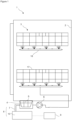
Figure 1 is a schematic view of the dishwasher. -
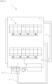
Figure 2 is a schematic view of the dishwasher in one embodiment. -
Figure 3 is a schematic view of the dishwasher in another embodiment. -
Figure 4 is a schematic view of the chamber, line and heat exchanger in an embodiment. -
Figure 5 is a schematic view of the chamber, line and heat exchanger in another embodiment. -
Figure 6 is a schematic view of the chamber, line and heat exchanger in a different embodiment. - The elements in the figure are numbered individually and the correspondence of these numbers are given hereinafter.
- 1- Dishwasher
- 2- Body
- 3- Washing space
- 4- Chamber
- 5- Filter
- 6- Pump
- 7- Line
- 8- Blower mechanism
- 9- Control unit
- 10- Air compressor
- 11- Drying duct
- 12- First fan
- 13- Heat pump
- 14- Heat exchanger
- 15- Second fan
- 16- Flap
- 17- Basket
- 18- Spray arm
- The dishwasher (1) comprises a body (2), a washing space (3) provided in the body (2), in which the washing and rinsing processes are performed, a chamber (4) provided on the base of the washing space (3), a filter (5) provided in the chamber (4), and a pump (6) enabling the water received from the mains into the chamber (4) to be sent to the washing space (3) and thus to be circulated. The baskets (17) in which the dishes to be washed are placed, are provided in the washing space (3), as well as the spray arms (18) above or below the baskets (17), enabling conveying the water transmitted by the pump (6) to the dishes. A user places the dishes into the washing space (3). The pump (6) draws from within the chamber (4) the water received from the mains, and sends it to the washing space (3). The water reaching the dishes in the washing space (3) flows back towards the base of the washing space (3), and is cleaned from dirt by passing though the filter (5) before being collected in the chamber (4). The pump (6) draws from the chamber (4) the filtered water and sends it back to the washing space (3), thereby enabling water circulation. After completion of the washing and rinsing processes, the water in the chamber (4) and the dirt particles collected on the filter (5) are discharged by means of a discharge pump (not shown in the figures).
- The dishwasher (1) of the invention comprises a blower mechanism (8) having a line (7) extending into the chamber (4), and a control unit (9) enabling sending air by means of the blower mechanism (8), on the filter (5) in the direction from the chamber (4) to the filter (5). The line (7) extends into the chamber (4) towards the filter (5). The blower mechanism (8) thus blows air on the outer surface of the filter (5) inwards from outside, enabling removal of the dirt particles stuck on the filter (5) surface, towards the center of the filter (5) which generally has a cylindrical structure. By this, the water is prevented from being trapped in the filter (5) due to filter (5) blockage, enabling smooth circulation. The air blown through the line (7) by means of the blower mechanism (8), is pressurized enough so as not to allow water to be introduced in to the line (7) due to the chamber (4) being filled with water.
- In an embodiment of the invention, the control unit (9) enables air to be blown on the filter (5) in washing and/or rinsing steps. The control unit (9) enables blowing air on the filter (5) in washing and rinsing steps in which the filter (5) is the most likely to be blocked, thereby enabling the washing and rinsing processes to be performed without blockage of the filter (5).
- In another embodiment of the invention, the control unit (9) enables air to be blown on the filter (5) when the flow rate of the pump (6) decreases in washing or rinsing steps. The control unit (9) continuously monitors the flow rate of the pump (6). When the filter (5) is blocked by dirt particles stuck thereon, the flow rate of the water pumped by the pump (6) decreases, and the pump (6) begins drawing more power. In such a case, the control unit (9) enables eliminating filter (5) blockage by enabling air to be blown on the outer surface of the filter (5) by means of the blower mechanism (8). This embodiment makes it unnecessary to continually blow air on the filter (5), and the control unit (9) activates the blower mechanism (8) only when required upon decreasing of the flow rate of the pump (6) which indicates of filter (5) blockage.
- In another embodiment of the invention, the blower mechanism (8) comprises an air compressor (10) provided in the body (2), blowing air into the line (7). The air compressor (10) blows air while connected to the free end of the line (7). The control unit (9) controls the air compressor (10).
- In another embodiment of the invention, the dishwasher (1) comprises a drying duct (11) provided in the body (2), in which the water evaporated from the washed dishes, is condensed, and a first fan (12) enabling circulation of the air in the drying duct (11), and an end of the line (7) extends to the first fan (12), and the control unit (9) enables blowing air into the line (7) by controlling the first fan (12). After the washing and rinsing processes, the control unit (9) controls the first fan (12) and circulates air between the drying duct (11) and the washing space (3), and enables the water evaporated from the dishes to be condensed on the drying duct (11) which has a cold surface. In this embodiment, an end of the line (7) extends to the vicinity of the first fan (12), and air is blown into the line (7) when the first fan (12) operates. Whether in washing or rinsing step, when air is to be blown on the filter (5), the control unit (9) activates the first fan (12) and enables air to be blown into the line (7). By means of this embodiment, in order to obtain air to be blown for eliminating filter (5) blockage, using an external air compressor (10) or another air supply unit becomes unnecessary and the required air is provided by means of the first fan (12) used in drying step.
- In another embodiment of the invention, the dishwasher (1) comprises a heat pump (13) having at least one heat exchanger (14) enabling heating the water received from the mains, and a second fan (15) blowing air on the heat exchanger (14), and an end of the line (7) extends to the second fan (15) and the control unit (9) enables blowing air into the line (7) by controlling the second fan (15). Likewise the above-disclosed embodiment, when air is to be blown on the filter (5), the control unit (9) activates the second fan (15) and enables air to be blown into the line (7). Also in this embodiment, elements already provided in the dishwasher (1) are used in order to provide air to be blown to clean the filter (5), avoiding an additional cost increase for cleaning the filter (5).
- In another embodiment of the invention, the control unit (9) enables blowing air on the filter (5) when the water heating duration of the heat pump (13) is longer than a predetermined limit duration. The amount of water transmitted to the heat pump (13) decreases when the filter (5) is blocked, decreasing the heat transfer amount on the heat exchanger (14) whose surface is hot. This prolongs the heating duration of water to be used in washing. The control unit (9) compares the heating duration with a limit duration predetermined preferably according to each washing program by the producer and when the heating duration is longer than the limit duration the control unit determines that the filter (5) is blocked and enables blowing air on the filter (5). The control unit (9) may enable blowing air on the filter (5) by considering only the water heating duration of the heat pump (13), as well as also by checking the flow rate of the pump (6) as in an above-disclosed embodiment, together with this embodiment. The control unit (9) can thus fully detect blockage of the filter (5), avoiding excessive energy consumption by enabling air to be blown on the filter (5) only when required.
- In another embodiment of the invention, the end of the line (7) extends between the heat exchanger (14) and the second fan (15) in air flow direction. In this embodiment, the air blown by the second fan (15) is sent into the line (7) without passing via the heat exchanger (14), i.e. without the air temperature being decreased or increased.
- In a version of this embodiment, the dishwasher (1) comprises a flap (16) having a closed position in which the air flow to the heat exchanger (14) is blocked, and the control unit (9) enables the flap (16) to switch to the closed position when air is to be blown into the line (7). All of the air provided by the second fan (15) is enabled to be sent into the line (7) thanks to this embodiment.
- In another embodiment of the invention, the end of the line (7) is disposed after the heat exchanger (14) in air flow direction, and the air passed via the heat exchanger (14) is transmitted into the line (7). Generally in heat pump (13) systems, heat is drawn from the outer environment by transferring air from the outer environment on to a heat exchanger (14) which has a cold surface. Likewise, the surface of the heat exchanger (14) is also cold in this embodiment, therefore the temperature of the air blown by the second fan (15) decreases after passing over the heat exchanger (14). Since the end of the line (7) is after the heat exchanger (14), the air with decreased temperature enters the line (7) and is transmitted to the filter (5). The filter (5) is warmer than the outer environment because there is hot water in the chamber (4) during the washing and rinsing processes. By transmitting the air colder than the outer environment to the hot filter (5), the dirt particles are enabled to be separated/removed from the filter (5) surface also by the effect created by the difference in temperatures in addition to the repulsion effect of air.
- In another embodiment of the invention, the line (7) winds around the heat exchanger (14) which has a hot surface. The temperature of the air blown on the filter (5) is equal to the outer environment temperature or is lower than the outer environment temperature as disclosed in the above embodiment. This causes the temperature of the washing water in the chamber (4) to decrease up to a certain extent. By means of this embodiment, i.e. by winding the line (7) around the heat exchanger (14) having a hot surface, the air in the line (7) is enabled to be heated, preventing the washing water temperature from decreasing.
- In another embodiment of the invention, the cross-section of the line (7) narrows down towards the filter (5). The velocity and the pressure of the air blown on the filter (5) is thus increased, thereby avoiding introduction of water into the line (7).
- In another embodiment of the invention, the blower mechanism (8) comprises a nozzle (not shown in the figures) provided on the end of the line (7), which does not allow liquid to pass therethrough. The nozzle only allows passage of air and blocks liquid passage. Thus, water may not pass into the line (7) even when the air blown on the filter (5) is not sufficiently pressurized.
- In another embodiment of the invention, the blower mechanism (8) comprises a nozzle (not shown in the figures) provided on the end of the line (7), not allowing passage through the filter (5) in the direction of the line (7). The nozzle functions as a non-return valve and allows passage only through the line (7) in the direction of the filter (5). Water is thus prevented from being introduced into the line (7). The nozzle may be adapted to allow only air passage like the above embodiment, as well as being adapted to allow passage in one direction as disclosed in this embodiment.
- In the dishwasher (1) of the invention, thanks to the control unit (9) and the blower mechanism (8) enabling blowing air on the filter (5), filter (5) blockage is avoided particularly during the washing and rinsing processes, preventing the overall washing duration from being prolonged. By avoiding filter (5) blockage, straining of the pump (6) and the other members are averted, enabling the useful lifetime of the dishwasher (1) to be prolonged.
Claims (13)
- A dishwasher (1) comprising a body (2), a washing space (3) provided in the body (2), in which the washing and rinsing processes are performed, a chamber (4) provided on the base of the washing space (3), a filter (5) provided in the chamber (4), and a pump (6) enabling the water received from the mains into the chamber (4) to be sent to the washing space (3) and thus to be circulated, characterized by a blower mechanism (8) having a line (7) extending into the chamber (4), and by a control unit (9) configured to operate the blower mechanism (8) to blow air on the filter (5) in the direction from the chamber (4) to the filter (5) such that dirt particles on the filter (5) surface are removed therefrom by the air blown by the blower mechanism (8).
- A dishwasher (1) according to claim 1, characterized by the control unit (9) configured to operate the blower mechanism (8) to blow air on the filter (5) in washing and/or rinsing steps.
- A dishwasher (1) according to claim 2, characterized by the control unit (9) configured to operate the blower mechanism (8) to blow air on the filter (5) when the flow rate of the pump (6) decreases in washing or rinsing steps.
- A dishwasher (1) according to any one of the claims 1 to 3, characterized by the blower mechanism (8) comprising an air compressor (10) provided in the body (2), for blowing air into the line (7).
- A dishwasher (1) according to any one of the claims 1 to 3, characterized by a drying duct (11) provided in the body (2), in which the water evaporating from the washed dishes is condensed, a first fan (12) enabling circulation of the air in the drying duct (11), a line (7) one of whose ends extends to the first fan (12), and by the control unit (9) configured to control the first fan (12) to blow air into the line (7).
- A dishwasher (1) according to any one of the claims 1 to 3, characterized by a heat pump (13) having at least one heat exchanger (14) and enabling heating the water received from the mains, a second fan (15) for blowing air on the heat exchanger (14), wherein one end of the line (7) extends to the second fan (15), and by the control unit (9) configured to control the second fan (15) to blow air into the line (7).
- A dishwasher (1) according to claim 6, characterized by the control unit (9) configured to control the second fan (15) to blow air on the filter (5) when the water heating duration of the heat pump (13) is longer than a predetermined limit duration.
- A dishwasher (1) according to claim 6 or 7, characterized by the line (7) whose end extends between the heat exchanger (14) and the second fan (15) in air flow direction.
- A dishwasher (1) according to claim 8, characterized by a flap (16) having a closed position in which the air flow to the heat exchanger (14) is blocked, and by the control unit (9) configured to control the flap (16) to switch to the closed position when air is to be blown into the line (7).
- A dishwasher (1) according to claim 6 or 7, characterized by the line (7) whose end is disposed after the heat exchanger (14) in air flow direction, and into which the air passed over the heat exchanger (14) is transmitted.
- A dishwasher (1) according to any one of the claims 6 to 10, characterized by the line (7) wound around the heat exchanger (14) whose surface is hot.
- A dishwasher (1) according to any one of the preceding claims, characterized by the line (7) whose cross-section narrows down towards the filter (5).
- A dishwasher (1) according to any one of the preceding claims, characterized by a nozzle provided at the end of the line (7) closer to the filter (5), wherein the nozzle is arranged to allow liquid passage only in the direction from the line (7) towards the filter (5).
Applications Claiming Priority (2)
| Application Number | Priority Date | Filing Date | Title |
|---|---|---|---|
| TR201721449 | 2017-12-25 | ||
| PCT/TR2018/050574 WO2019132808A1 (en) | 2017-12-25 | 2018-10-09 | A dishwasher comprising a micro-filter |
Publications (3)
| Publication Number | Publication Date |
|---|---|
| EP3731721A1 EP3731721A1 (en) | 2020-11-04 |
| EP3731721A4 EP3731721A4 (en) | 2021-09-08 |
| EP3731721B1 true EP3731721B1 (en) | 2023-08-02 |
Family
ID=67067975
Family Applications (1)
| Application Number | Title | Priority Date | Filing Date |
|---|---|---|---|
| EP18894309.6A Active EP3731721B1 (en) | 2017-12-25 | 2018-10-09 | A dishwasher comprising a micro-filter |
Country Status (3)
| Country | Link |
|---|---|
| EP (1) | EP3731721B1 (en) |
| PL (1) | PL3731721T3 (en) |
| WO (1) | WO2019132808A1 (en) |
Family Cites Families (11)
| Publication number | Priority date | Publication date | Assignee | Title |
|---|---|---|---|---|
| SE425289C (en) * | 1978-08-31 | 1985-09-09 | Wexioedisk Ab | SET TO SAVE ENERGY AND COOLING FROM THE DISHWASHER WITH A BAND DISHWASHER AND DEVICE FOR IMPLEMENTING THE SET |
| US5127417A (en) * | 1990-12-28 | 1992-07-07 | Whirlpool Corporation | Soil separator for a dishwasher |
| JP2002112942A (en) * | 2000-10-11 | 2002-04-16 | Japan Crescent Co Ltd | Method and mechanism for washing dishes |
| DE10249130A1 (en) | 2002-10-22 | 2004-05-06 | Electrolux Home Products Corporation N.V. | A method for clearing the filter in the liquid circulation system of domestic appliances has a soundwave generator positioned in the sump |
| DE102007061038B4 (en) | 2007-12-18 | 2016-10-27 | BSH Hausgeräte GmbH | Water-conducting household appliance |
| US9687135B2 (en) * | 2009-12-21 | 2017-06-27 | Whirlpool Corporation | Automatic dishwasher with pump assembly |
| US20120138107A1 (en) | 2010-12-03 | 2012-06-07 | Whirlpool Corporation | Dishwasher with single pump and filter unit for multiple compartments |
| US20140069473A1 (en) * | 2012-09-13 | 2014-03-13 | Whirlpool Corporation | Dishwasher with disk sprayer |
| DE102014101260A1 (en) | 2013-04-03 | 2014-10-09 | Whirlpool Corporation (A Delaware Corporation) | Heating air for drying dishes in a dishwasher with continuous heating of the washing liquid |
| KR20160023294A (en) | 2014-08-22 | 2016-03-03 | 엘지전자 주식회사 | Control method for Dishwasher |
| CN104739352B (en) * | 2015-02-12 | 2018-11-27 | 佛山市顺德区美的洗涤电器制造有限公司 | Dish-washing machine |
-
2018
- 2018-10-09 EP EP18894309.6A patent/EP3731721B1/en active Active
- 2018-10-09 WO PCT/TR2018/050574 patent/WO2019132808A1/en not_active Ceased
- 2018-10-09 PL PL18894309.6T patent/PL3731721T3/en unknown
Also Published As
| Publication number | Publication date |
|---|---|
| EP3731721A1 (en) | 2020-11-04 |
| WO2019132808A1 (en) | 2019-07-04 |
| PL3731721T3 (en) | 2024-01-29 |
| EP3731721A4 (en) | 2021-09-08 |
Similar Documents
| Publication | Publication Date | Title |
|---|---|---|
| US8307839B2 (en) | Dishwasher with a latent heat accumulator | |
| EP2039819B1 (en) | Washer-drier machine | |
| US8603259B2 (en) | Conveyor warewasher and method for operating a conveyor warewasher | |
| RU2685025C1 (en) | Linen processing device and method of cleaning nozzles control | |
| CN107647834B (en) | Heat pump dishwasher | |
| EP3133974B1 (en) | Washer/disinfector | |
| CN108135428B (en) | Dishwasher with heat recovery system | |
| JP6473397B2 (en) | Cooling system | |
| EP2081479A1 (en) | Dish washing machine and control method of the same | |
| US10722097B2 (en) | Warewasher with heat recovery system | |
| US8888927B2 (en) | Rinsing method for a water-bearing domestic appliance, especially dishwasher | |
| CN108135430A (en) | Ware wash machine with heat recovery system | |
| EP3731718B1 (en) | A heat pump dishwasher | |
| AU2019200886B2 (en) | Dishwasher | |
| JP2007125198A (en) | Dishwasher | |
| CN108697296B (en) | Warewashing machine drying system and method | |
| EP3731719B1 (en) | A heat pump dishwasher with improved washing water heating performance | |
| WO2019132808A1 (en) | A dishwasher comprising a micro-filter | |
| EP4066722A1 (en) | A dishwasher providing heat recovery | |
| EP3777640A1 (en) | A dishwasher | |
| JP3195764B2 (en) | Dishwasher | |
| JPH08206054A (en) | dishwasher | |
| JPH1080394A (en) | Tableware dryer and tableware cleaning machine |
Legal Events
| Date | Code | Title | Description |
|---|---|---|---|
| STAA | Information on the status of an ep patent application or granted ep patent |
Free format text: STATUS: THE INTERNATIONAL PUBLICATION HAS BEEN MADE |
|
| PUAI | Public reference made under article 153(3) epc to a published international application that has entered the european phase |
Free format text: ORIGINAL CODE: 0009012 |
|
| STAA | Information on the status of an ep patent application or granted ep patent |
Free format text: STATUS: REQUEST FOR EXAMINATION WAS MADE |
|
| 17P | Request for examination filed |
Effective date: 20200527 |
|
| AK | Designated contracting states |
Kind code of ref document: A1 Designated state(s): AL AT BE BG CH CY CZ DE DK EE ES FI FR GB GR HR HU IE IS IT LI LT LU LV MC MK MT NL NO PL PT RO RS SE SI SK SM TR |
|
| AX | Request for extension of the european patent |
Extension state: BA ME |
|
| DAV | Request for validation of the european patent (deleted) | ||
| DAX | Request for extension of the european patent (deleted) | ||
| REG | Reference to a national code |
Ref country code: DE Ref legal event code: R079 Free format text: PREVIOUS MAIN CLASS: A47L0015480000 Ipc: A47L0015420000 Ref document number: 602018054792 Country of ref document: DE |
|
| A4 | Supplementary search report drawn up and despatched |
Effective date: 20210811 |
|
| RIC1 | Information provided on ipc code assigned before grant |
Ipc: A47L 15/48 20060101ALN20210805BHEP Ipc: A47L 15/42 20060101AFI20210805BHEP |
|
| GRAP | Despatch of communication of intention to grant a patent |
Free format text: ORIGINAL CODE: EPIDOSNIGR1 |
|
| STAA | Information on the status of an ep patent application or granted ep patent |
Free format text: STATUS: GRANT OF PATENT IS INTENDED |
|
| INTG | Intention to grant announced |
Effective date: 20230503 |
|
| GRAS | Grant fee paid |
Free format text: ORIGINAL CODE: EPIDOSNIGR3 |
|
| GRAA | (expected) grant |
Free format text: ORIGINAL CODE: 0009210 |
|
| STAA | Information on the status of an ep patent application or granted ep patent |
Free format text: STATUS: THE PATENT HAS BEEN GRANTED |
|
| AK | Designated contracting states |
Kind code of ref document: B1 Designated state(s): AL AT BE BG CH CY CZ DE DK EE ES FI FR GB GR HR HU IE IS IT LI LT LU LV MC MK MT NL NO PL PT RO RS SE SI SK SM TR |
|
| REG | Reference to a national code |
Ref country code: GB Ref legal event code: FG4D |
|
| REG | Reference to a national code |
Ref country code: CH Ref legal event code: EP |
|
| REG | Reference to a national code |
Ref country code: DE Ref legal event code: R096 Ref document number: 602018054792 Country of ref document: DE |
|
| REG | Reference to a national code |
Ref country code: IE Ref legal event code: FG4D |
|
| REG | Reference to a national code |
Ref country code: LT Ref legal event code: MG9D |
|
| REG | Reference to a national code |
Ref country code: NL Ref legal event code: MP Effective date: 20230802 |
|
| REG | Reference to a national code |
Ref country code: AT Ref legal event code: MK05 Ref document number: 1593686 Country of ref document: AT Kind code of ref document: T Effective date: 20230802 |
|
| PG25 | Lapsed in a contracting state [announced via postgrant information from national office to epo] |
Ref country code: GR Free format text: LAPSE BECAUSE OF FAILURE TO SUBMIT A TRANSLATION OF THE DESCRIPTION OR TO PAY THE FEE WITHIN THE PRESCRIBED TIME-LIMIT Effective date: 20231103 |
|
| PG25 | Lapsed in a contracting state [announced via postgrant information from national office to epo] |
Ref country code: IS Free format text: LAPSE BECAUSE OF FAILURE TO SUBMIT A TRANSLATION OF THE DESCRIPTION OR TO PAY THE FEE WITHIN THE PRESCRIBED TIME-LIMIT Effective date: 20231202 |
|
| PG25 | Lapsed in a contracting state [announced via postgrant information from national office to epo] |
Ref country code: SE Free format text: LAPSE BECAUSE OF FAILURE TO SUBMIT A TRANSLATION OF THE DESCRIPTION OR TO PAY THE FEE WITHIN THE PRESCRIBED TIME-LIMIT Effective date: 20230802 Ref country code: RS Free format text: LAPSE BECAUSE OF FAILURE TO SUBMIT A TRANSLATION OF THE DESCRIPTION OR TO PAY THE FEE WITHIN THE PRESCRIBED TIME-LIMIT Effective date: 20230802 Ref country code: PT Free format text: LAPSE BECAUSE OF FAILURE TO SUBMIT A TRANSLATION OF THE DESCRIPTION OR TO PAY THE FEE WITHIN THE PRESCRIBED TIME-LIMIT Effective date: 20231204 Ref country code: NO Free format text: LAPSE BECAUSE OF FAILURE TO SUBMIT A TRANSLATION OF THE DESCRIPTION OR TO PAY THE FEE WITHIN THE PRESCRIBED TIME-LIMIT Effective date: 20231102 Ref country code: NL Free format text: LAPSE BECAUSE OF FAILURE TO SUBMIT A TRANSLATION OF THE DESCRIPTION OR TO PAY THE FEE WITHIN THE PRESCRIBED TIME-LIMIT Effective date: 20230802 Ref country code: LV Free format text: LAPSE BECAUSE OF FAILURE TO SUBMIT A TRANSLATION OF THE DESCRIPTION OR TO PAY THE FEE WITHIN THE PRESCRIBED TIME-LIMIT Effective date: 20230802 Ref country code: LT Free format text: LAPSE BECAUSE OF FAILURE TO SUBMIT A TRANSLATION OF THE DESCRIPTION OR TO PAY THE FEE WITHIN THE PRESCRIBED TIME-LIMIT Effective date: 20230802 Ref country code: IS Free format text: LAPSE BECAUSE OF FAILURE TO SUBMIT A TRANSLATION OF THE DESCRIPTION OR TO PAY THE FEE WITHIN THE PRESCRIBED TIME-LIMIT Effective date: 20231202 Ref country code: HR Free format text: LAPSE BECAUSE OF FAILURE TO SUBMIT A TRANSLATION OF THE DESCRIPTION OR TO PAY THE FEE WITHIN THE PRESCRIBED TIME-LIMIT Effective date: 20230802 Ref country code: GR Free format text: LAPSE BECAUSE OF FAILURE TO SUBMIT A TRANSLATION OF THE DESCRIPTION OR TO PAY THE FEE WITHIN THE PRESCRIBED TIME-LIMIT Effective date: 20231103 Ref country code: FI Free format text: LAPSE BECAUSE OF FAILURE TO SUBMIT A TRANSLATION OF THE DESCRIPTION OR TO PAY THE FEE WITHIN THE PRESCRIBED TIME-LIMIT Effective date: 20230802 Ref country code: AT Free format text: LAPSE BECAUSE OF FAILURE TO SUBMIT A TRANSLATION OF THE DESCRIPTION OR TO PAY THE FEE WITHIN THE PRESCRIBED TIME-LIMIT Effective date: 20230802 |
|
| PG25 | Lapsed in a contracting state [announced via postgrant information from national office to epo] |
Ref country code: ES Free format text: LAPSE BECAUSE OF FAILURE TO SUBMIT A TRANSLATION OF THE DESCRIPTION OR TO PAY THE FEE WITHIN THE PRESCRIBED TIME-LIMIT Effective date: 20230802 |
|
| PG25 | Lapsed in a contracting state [announced via postgrant information from national office to epo] |
Ref country code: SM Free format text: LAPSE BECAUSE OF FAILURE TO SUBMIT A TRANSLATION OF THE DESCRIPTION OR TO PAY THE FEE WITHIN THE PRESCRIBED TIME-LIMIT Effective date: 20230802 Ref country code: RO Free format text: LAPSE BECAUSE OF FAILURE TO SUBMIT A TRANSLATION OF THE DESCRIPTION OR TO PAY THE FEE WITHIN THE PRESCRIBED TIME-LIMIT Effective date: 20230802 Ref country code: ES Free format text: LAPSE BECAUSE OF FAILURE TO SUBMIT A TRANSLATION OF THE DESCRIPTION OR TO PAY THE FEE WITHIN THE PRESCRIBED TIME-LIMIT Effective date: 20230802 Ref country code: EE Free format text: LAPSE BECAUSE OF FAILURE TO SUBMIT A TRANSLATION OF THE DESCRIPTION OR TO PAY THE FEE WITHIN THE PRESCRIBED TIME-LIMIT Effective date: 20230802 Ref country code: DK Free format text: LAPSE BECAUSE OF FAILURE TO SUBMIT A TRANSLATION OF THE DESCRIPTION OR TO PAY THE FEE WITHIN THE PRESCRIBED TIME-LIMIT Effective date: 20230802 Ref country code: CZ Free format text: LAPSE BECAUSE OF FAILURE TO SUBMIT A TRANSLATION OF THE DESCRIPTION OR TO PAY THE FEE WITHIN THE PRESCRIBED TIME-LIMIT Effective date: 20230802 Ref country code: SK Free format text: LAPSE BECAUSE OF FAILURE TO SUBMIT A TRANSLATION OF THE DESCRIPTION OR TO PAY THE FEE WITHIN THE PRESCRIBED TIME-LIMIT Effective date: 20230802 |
|
| REG | Reference to a national code |
Ref country code: DE Ref legal event code: R097 Ref document number: 602018054792 Country of ref document: DE |
|
| PG25 | Lapsed in a contracting state [announced via postgrant information from national office to epo] |
Ref country code: IT Free format text: LAPSE BECAUSE OF FAILURE TO SUBMIT A TRANSLATION OF THE DESCRIPTION OR TO PAY THE FEE WITHIN THE PRESCRIBED TIME-LIMIT Effective date: 20230802 Ref country code: MC Free format text: LAPSE BECAUSE OF FAILURE TO SUBMIT A TRANSLATION OF THE DESCRIPTION OR TO PAY THE FEE WITHIN THE PRESCRIBED TIME-LIMIT Effective date: 20230802 |
|
| REG | Reference to a national code |
Ref country code: CH Ref legal event code: PL |
|
| PLBE | No opposition filed within time limit |
Free format text: ORIGINAL CODE: 0009261 |
|
| STAA | Information on the status of an ep patent application or granted ep patent |
Free format text: STATUS: NO OPPOSITION FILED WITHIN TIME LIMIT |
|
| REG | Reference to a national code |
Ref country code: BE Ref legal event code: MM Effective date: 20231031 |
|
| PG25 | Lapsed in a contracting state [announced via postgrant information from national office to epo] |
Ref country code: LU Free format text: LAPSE BECAUSE OF NON-PAYMENT OF DUE FEES Effective date: 20231009 |
|
| PG25 | Lapsed in a contracting state [announced via postgrant information from national office to epo] |
Ref country code: LU Free format text: LAPSE BECAUSE OF NON-PAYMENT OF DUE FEES Effective date: 20231009 |
|
| 26N | No opposition filed |
Effective date: 20240503 |
|
| PG25 | Lapsed in a contracting state [announced via postgrant information from national office to epo] |
Ref country code: CH Free format text: LAPSE BECAUSE OF NON-PAYMENT OF DUE FEES Effective date: 20231031 |
|
| GBPC | Gb: european patent ceased through non-payment of renewal fee |
Effective date: 20231102 |
|
| PG25 | Lapsed in a contracting state [announced via postgrant information from national office to epo] |
Ref country code: FR Free format text: LAPSE BECAUSE OF NON-PAYMENT OF DUE FEES Effective date: 20231031 Ref country code: CH Free format text: LAPSE BECAUSE OF NON-PAYMENT OF DUE FEES Effective date: 20231031 Ref country code: SI Free format text: LAPSE BECAUSE OF FAILURE TO SUBMIT A TRANSLATION OF THE DESCRIPTION OR TO PAY THE FEE WITHIN THE PRESCRIBED TIME-LIMIT Effective date: 20230802 |
|
| PG25 | Lapsed in a contracting state [announced via postgrant information from national office to epo] |
Ref country code: BE Free format text: LAPSE BECAUSE OF NON-PAYMENT OF DUE FEES Effective date: 20231031 |
|
| PG25 | Lapsed in a contracting state [announced via postgrant information from national office to epo] |
Ref country code: IE Free format text: LAPSE BECAUSE OF NON-PAYMENT OF DUE FEES Effective date: 20231009 |
|
| PG25 | Lapsed in a contracting state [announced via postgrant information from national office to epo] |
Ref country code: GB Free format text: LAPSE BECAUSE OF NON-PAYMENT OF DUE FEES Effective date: 20231102 |
|
| PG25 | Lapsed in a contracting state [announced via postgrant information from national office to epo] |
Ref country code: IE Free format text: LAPSE BECAUSE OF NON-PAYMENT OF DUE FEES Effective date: 20231009 Ref country code: GB Free format text: LAPSE BECAUSE OF NON-PAYMENT OF DUE FEES Effective date: 20231102 |
|
| PG25 | Lapsed in a contracting state [announced via postgrant information from national office to epo] |
Ref country code: BG Free format text: LAPSE BECAUSE OF FAILURE TO SUBMIT A TRANSLATION OF THE DESCRIPTION OR TO PAY THE FEE WITHIN THE PRESCRIBED TIME-LIMIT Effective date: 20230802 |
|
| PG25 | Lapsed in a contracting state [announced via postgrant information from national office to epo] |
Ref country code: BG Free format text: LAPSE BECAUSE OF FAILURE TO SUBMIT A TRANSLATION OF THE DESCRIPTION OR TO PAY THE FEE WITHIN THE PRESCRIBED TIME-LIMIT Effective date: 20230802 |
|
| PG25 | Lapsed in a contracting state [announced via postgrant information from national office to epo] |
Ref country code: CY Free format text: LAPSE BECAUSE OF FAILURE TO SUBMIT A TRANSLATION OF THE DESCRIPTION OR TO PAY THE FEE WITHIN THE PRESCRIBED TIME-LIMIT; INVALID AB INITIO Effective date: 20181009 |
|
| PG25 | Lapsed in a contracting state [announced via postgrant information from national office to epo] |
Ref country code: HU Free format text: LAPSE BECAUSE OF FAILURE TO SUBMIT A TRANSLATION OF THE DESCRIPTION OR TO PAY THE FEE WITHIN THE PRESCRIBED TIME-LIMIT; INVALID AB INITIO Effective date: 20181009 |
|
| PGFP | Annual fee paid to national office [announced via postgrant information from national office to epo] |
Ref country code: PL Payment date: 20250925 Year of fee payment: 8 Ref country code: TR Payment date: 20250930 Year of fee payment: 8 |
|
| PGFP | Annual fee paid to national office [announced via postgrant information from national office to epo] |
Ref country code: DE Payment date: 20251021 Year of fee payment: 8 |