EP3731442B1 - Determining method and system for real-time driving speed of train and related devices - Google Patents
Determining method and system for real-time driving speed of train and related devices Download PDFInfo
- Publication number
- EP3731442B1 EP3731442B1 EP17935459.2A EP17935459A EP3731442B1 EP 3731442 B1 EP3731442 B1 EP 3731442B1 EP 17935459 A EP17935459 A EP 17935459A EP 3731442 B1 EP3731442 B1 EP 3731442B1
- Authority
- EP
- European Patent Office
- Prior art keywords
- running speed
- real
- time running
- speed
- train
- Prior art date
- Legal status (The legal status is an assumption and is not a legal conclusion. Google has not performed a legal analysis and makes no representation as to the accuracy of the status listed.)
- Active
Links
- 238000000034 method Methods 0.000 title claims description 55
- 238000012937 correction Methods 0.000 claims description 35
- 230000005856 abnormality Effects 0.000 claims description 17
- 238000004891 communication Methods 0.000 claims description 12
- 238000004590 computer program Methods 0.000 claims description 12
- 108010001267 Protein Subunits Proteins 0.000 claims description 5
- 238000012935 Averaging Methods 0.000 claims description 3
- 238000010586 diagram Methods 0.000 description 10
- 230000002159 abnormal effect Effects 0.000 description 4
- 238000006243 chemical reaction Methods 0.000 description 4
- 238000005259 measurement Methods 0.000 description 4
- 238000005516 engineering process Methods 0.000 description 3
- 230000006870 function Effects 0.000 description 3
- 230000009286 beneficial effect Effects 0.000 description 2
- 238000004364 calculation method Methods 0.000 description 2
- 238000013461 design Methods 0.000 description 2
- 238000012545 processing Methods 0.000 description 2
- 230000015572 biosynthetic process Effects 0.000 description 1
- 238000004422 calculation algorithm Methods 0.000 description 1
- 238000007796 conventional method Methods 0.000 description 1
- 230000007812 deficiency Effects 0.000 description 1
- 238000011161 development Methods 0.000 description 1
- 238000005755 formation reaction Methods 0.000 description 1
- 230000003137 locomotive effect Effects 0.000 description 1
- 230000000750 progressive effect Effects 0.000 description 1
Images


Classifications
-
- B—PERFORMING OPERATIONS; TRANSPORTING
- B60—VEHICLES IN GENERAL
- B60T—VEHICLE BRAKE CONTROL SYSTEMS OR PARTS THEREOF; BRAKE CONTROL SYSTEMS OR PARTS THEREOF, IN GENERAL; ARRANGEMENT OF BRAKING ELEMENTS ON VEHICLES IN GENERAL; PORTABLE DEVICES FOR PREVENTING UNWANTED MOVEMENT OF VEHICLES; VEHICLE MODIFICATIONS TO FACILITATE COOLING OF BRAKES
- B60T8/00—Arrangements for adjusting wheel-braking force to meet varying vehicular or ground-surface conditions, e.g. limiting or varying distribution of braking force
- B60T8/17—Using electrical or electronic regulation means to control braking
- B60T8/172—Determining control parameters used in the regulation, e.g. by calculations involving measured or detected parameters
-
- B—PERFORMING OPERATIONS; TRANSPORTING
- B61—RAILWAYS
- B61L—GUIDING RAILWAY TRAFFIC; ENSURING THE SAFETY OF RAILWAY TRAFFIC
- B61L25/00—Recording or indicating positions or identities of vehicles or vehicle trains or setting of track apparatus
- B61L25/02—Indicating or recording positions or identities of vehicles or vehicle trains
- B61L25/021—Measuring and recording of train speed
-
- B—PERFORMING OPERATIONS; TRANSPORTING
- B60—VEHICLES IN GENERAL
- B60T—VEHICLE BRAKE CONTROL SYSTEMS OR PARTS THEREOF; BRAKE CONTROL SYSTEMS OR PARTS THEREOF, IN GENERAL; ARRANGEMENT OF BRAKING ELEMENTS ON VEHICLES IN GENERAL; PORTABLE DEVICES FOR PREVENTING UNWANTED MOVEMENT OF VEHICLES; VEHICLE MODIFICATIONS TO FACILITATE COOLING OF BRAKES
- B60T8/00—Arrangements for adjusting wheel-braking force to meet varying vehicular or ground-surface conditions, e.g. limiting or varying distribution of braking force
- B60T8/17—Using electrical or electronic regulation means to control braking
- B60T8/1701—Braking or traction control means specially adapted for particular types of vehicles
- B60T8/1705—Braking or traction control means specially adapted for particular types of vehicles for rail vehicles
-
- B—PERFORMING OPERATIONS; TRANSPORTING
- B60—VEHICLES IN GENERAL
- B60W—CONJOINT CONTROL OF VEHICLE SUB-UNITS OF DIFFERENT TYPE OR DIFFERENT FUNCTION; CONTROL SYSTEMS SPECIALLY ADAPTED FOR HYBRID VEHICLES; ROAD VEHICLE DRIVE CONTROL SYSTEMS FOR PURPOSES NOT RELATED TO THE CONTROL OF A PARTICULAR SUB-UNIT
- B60W40/00—Estimation or calculation of non-directly measurable driving parameters for road vehicle drive control systems not related to the control of a particular sub unit, e.g. by using mathematical models
- B60W40/10—Estimation or calculation of non-directly measurable driving parameters for road vehicle drive control systems not related to the control of a particular sub unit, e.g. by using mathematical models related to vehicle motion
- B60W40/105—Speed
-
- B—PERFORMING OPERATIONS; TRANSPORTING
- B60—VEHICLES IN GENERAL
- B60T—VEHICLE BRAKE CONTROL SYSTEMS OR PARTS THEREOF; BRAKE CONTROL SYSTEMS OR PARTS THEREOF, IN GENERAL; ARRANGEMENT OF BRAKING ELEMENTS ON VEHICLES IN GENERAL; PORTABLE DEVICES FOR PREVENTING UNWANTED MOVEMENT OF VEHICLES; VEHICLE MODIFICATIONS TO FACILITATE COOLING OF BRAKES
- B60T2210/00—Detection or estimation of road or environment conditions; Detection or estimation of road shapes
- B60T2210/30—Environment conditions or position therewithin
- B60T2210/36—Global Positioning System [GPS]
-
- B—PERFORMING OPERATIONS; TRANSPORTING
- B60—VEHICLES IN GENERAL
- B60T—VEHICLE BRAKE CONTROL SYSTEMS OR PARTS THEREOF; BRAKE CONTROL SYSTEMS OR PARTS THEREOF, IN GENERAL; ARRANGEMENT OF BRAKING ELEMENTS ON VEHICLES IN GENERAL; PORTABLE DEVICES FOR PREVENTING UNWANTED MOVEMENT OF VEHICLES; VEHICLE MODIFICATIONS TO FACILITATE COOLING OF BRAKES
- B60T2250/00—Monitoring, detecting, estimating vehicle conditions
- B60T2250/04—Vehicle reference speed; Vehicle body speed
-
- B—PERFORMING OPERATIONS; TRANSPORTING
- B60—VEHICLES IN GENERAL
- B60W—CONJOINT CONTROL OF VEHICLE SUB-UNITS OF DIFFERENT TYPE OR DIFFERENT FUNCTION; CONTROL SYSTEMS SPECIALLY ADAPTED FOR HYBRID VEHICLES; ROAD VEHICLE DRIVE CONTROL SYSTEMS FOR PURPOSES NOT RELATED TO THE CONTROL OF A PARTICULAR SUB-UNIT
- B60W2556/00—Input parameters relating to data
- B60W2556/45—External transmission of data to or from the vehicle
- B60W2556/50—External transmission of data to or from the vehicle for navigation systems
Definitions
- the present invention relates to the technical field of train network control, and in particular to a method, a system, and an apparatus for determining a real-time running speed of a train, and a computer readable storage medium.
- a method for determining at least one speed in a rail vehicle is provided.
- a chassis speed measurement variable is provided by a sensor unit.
- Inertial measurement variables are detected by an inertial measurement unit; a reference speed characteristic value is formed; an inertial speed characteristic value is determined by a calculation unit based on the inertial measurement variables, in a first operating mode, to estimate a deviation in the inertial calculation based on the reference speed characteristic value; the inertial speed characteristic value is determined, in a second operating mode, without taking into account the reference speed characteristic value.
- a method for determining a real-time running speed of a train which integrates a rotation speed of a traction motor obtained from a traction unit, an axle speed of a target axle obtained from a braking control unit, and a real-time running speed of a train provided by a GPS and uses the above parameters from different sources to provide different schemes for different actual train running speeds.
- a system, an apparatus and a computer readable storage medium for determining a real-time running speed of a train are also provided.
- the method for determining a real-time running speed of a train includes the following steps.
- An axle speed of a target axle in a braking system and rotation speeds of one or more traction motors in a traction system in a target train are acquired.
- the rotation speeds are converted into a first real-time running speed by using a preset correspondence between a traction motor rotation speed and a train running speed in a case where the traction system is in a normal state.
- the axle speed is converted into a second real-time running speed by using a preset correspondence between the axle speed and the train running speed in a case where the braking system is in a normal state.
- the second real-time running speed is determined as an effective real-time running speed of the target train in a case where both the traction system and the braking system are in the normal state. It is determined whether the effective real-time running speed is greater than a preset running speed threshold, a third real-time running speed measured by a GPS is utilized to correct the effective real-time running speed in a case where the effective running speed is greater than the preset running speed threshold.
- the traction system is determined to be in the normal state by the method including: determining whether each of traction units in the traction system is in a normal data communication state; determining whether an abnormality occurs in a process of acquiring the rotation speeds of the one or more traction motors in a case where each of the traction units is in the normal data communication state; determining whether any one of acquired rotation speeds exceeds a preset rotation speed range in a case where no abnormality occurs in the process of acquiring the rotation speeds of the one or more traction motors; determining that the traction system is in the normal state in a case where none of the acquired rotation speeds exceeds the preset rotation speed range.
- the braking system is determined to be in the normal state by the method including: determining whether the braking system is in a preset failure state; determining whether an abnormality occurs in the target axle in a case where the braking system is not in the preset failure state; determining whether the braking system is in a normal data communication state in a case where no abnormality occurs in the target axle; determining that the braking system is in the normal state in a case where the braking system is in the normal data communication state.
- the method further includes: acquiring rotation speeds of one or more traction motors in all of the traction systems; obtaining temporary values of the first real-time running speeds by converting the rotation speeds by using the preset correspondence between the traction motor rotation speed and the train running speed; averaging all the temporary values of the first real-time running speed to obtain the first real-time running speed.
- the method further includes: determining the first real-time running speed as the effective real-time running speed in a case where an abnormality occurs in the braking system and the traction system is in the normal state.
- the correcting the effective real-time running speed by using a third real-time running speed measured by a GPS includes: measuring the real-time running speed of the target train by using the GPS to obtain the third real-time running speed; calculating a ratio between the third real-time running speed and the effective real-time running speed to obtain a correction parameter; and correcting the effective real-time running speed by using the correction parameter.
- the system for determining a real-time running speed of a train includes: a parameter acquiring unit, a first running speed determining unit, a second running speed determining unit, an effective running speed determining unit and a determination and correction unit.
- the parameter acquiring unit is configured to acquire an axle speed of a target axle in a braking system and a rotation speed of a traction motor in a traction system in a target train.
- the first running speed determining unit is configured to convert the rotation speed into a first real-time running speed by using a preset correspondence between a traction motor rotation speed and a train running speed in a case where the traction system is in a normal state.
- the second running speed determining unit is configured to convert the axle speed into a second real-time running speed by using a preset correspondence between the axle speed and the train running speed in a case where the braking system is in the normal state.
- the effective running speed determining unit is configured to determine the second real-time running speed as an effective real-time running speed of the target train in a case where both the traction system and the braking system are in the normal state.
- the determination and correction unit is configured to determine whether the effective real-time running speed is greater than a preset running speed threshold and correct the effective real-time running speed by using a third real-time running speed measured by a GPS in a case where the effective running speed is greater than the preset running speed threshold.
- the determination and correction unit includes: a GPS measuring sub-unit, a correction parameter calculating sub-unit and a correction sub-unit.
- the GPS measuring sub-unit is configured to measure the real-time running speed of the target train by using the GPS to obtain the third real-time running speed.
- the correction parameter calculating sub-unit is configured to calculate a ratio between the third real-time running speed and the effective real-time running speed to obtain a correction parameter.
- the correction sub-unit is configured to correct the effective real-time running speed by using the correction parameter.
- the apparatus for determining a real-time running speed of a train includes: a storage medium and a processor.
- the storage medium is configured to store computer programs.
- the processor is configured to perform steps of the above method for determining a real-time running speed of a train when executing the computer programs.
- the computer readable storage medium stores computer programs.
- the computer program when executed by a processor, causes the processor to perform the method for determining a real-time running speed of a train.
- an axle speed of a target axle in a braking system and a rotation speed of a traction motor in a traction system in a target train are acquired.
- the rotation speed is converted into a first real-time running speed by using a preset correspondence between a traction motor rotation speed and a train running speed in a case where the traction system is in a normal state.
- the axle speed is converted into a second real-time running speed by using a preset correspondence between the axle speed and the train running speed in a case where the braking system is in the normal state.
- the second real-time running speed is determined as an effective real-time running speed of the target train in a case where both the traction system and the braking system are in the normal state. It is determined whether the effective real-time running speed is greater than a preset running speed threshold.
- a third real-time running speed measured by a GPS is utilized to correct the effective real-time running speed in a case where the effective running speed is greater than the preset running speed threshold.
- the technical solution provided according to the present invention integrates a rotation speed of a traction motor obtained from a traction unit, an axle speed of a target axle obtained from a braking control unit, and a real-time running speed of the train provided by a GPS and uses the above parameters from different sources to provide different schemes for different actual train running speeds.
- a more accurate real-time running speed of the train can be obtained, which facilitate subsequent intelligent control of the train.
- a determination system and an apparatus for determining a real-time running speed of a train and a computer readable storage medium are further provided according to the present invention, which have the above beneficial effects and are not repeated herein.
- a method, a system, and an apparatus for determining a real-time running speed of a train and a computer readable storage medium are provided in the present invention, which integrates a rotation speed of a traction motor obtained from a traction unit, an axle speed of a target axle obtained from a braking control unit, and a real-time running speed of a train provided by a GPS and uses the above parameters from different sources to provide different schemes for different actual train running speeds.
- Figure 1 is a schematic flow diagram of a method for determining a real-time running speed of a train according to an embodiment of the present invention.
- the method includes the following steps S101 to S 107.
- step S101 an axle speed of a target axle in a braking system and a rotation speed of a traction motor in a traction system in a target train are acquired.
- the braking system is responsible for controlling braking of the train, and thus it monitors the axle speed of each of the train axles.
- the target axle is a representative axle selected from all the train axles.
- a real-time running speed of the train converted from the axle speed of the target axle can best reflect a true real-time running speed, and thus it is used with a highest priority.
- the traction system provides traction for the target train, the most important part of which is the traction motor.
- the rotation speed of the traction motor acquired from the traction system is also utilized to calculate the real-time running speed of the train.
- Each traction system may include different numbers of traction motors.
- the target axle is determined from all the train axles in the braking system based on a preset selection rule, and the axle speed is obtained by using a corresponding axle speed sensor. For example, in a multiple-unit train with eight carriages, an axle 3 in train axles of a locomotive may be selected as the target axle, and the axle speed of the target axle is required to be obtained.
- step S102 the rotation speed is converted into a first real-time running speed by using a preset correspondence between a traction motor rotation speed and a train running speed in a case where the traction system is in a normal state.
- step S101 the rotation speed is converted into a first real-time running speed by using a preset correspondence between a traction motor rotation speed and a train running speed in a case where the traction system is in a normal state.
- this step may be changed as follows for example.
- the rotation speed of the traction motor in each of the traction systems is acquired.
- a corresponding numbers of temporary values of the first real-time running speed are obtained by converting the rotation speeds by using the preset correspondence between the traction motor rotation speed and the train running speed. Then an average of the temporary values of the first real-time running speed is calculated to obtain the first real-time running speed.
- step S103 the axle speed is converted into a second real-time running speed by using a preset correspondence between the axle speed and the train running speed in a case where the braking system is in a normal state.
- step S101 the axle speed is converted into a second real-time running speed by using a preset correspondence between the axle speed and the train running speed in a case where the braking system is in a normal state.
- the normal states of the traction system and the braking system in steps S 102 and S103 are used to indicate that the actual working state of the traction motor and the target axle is normal and thus the rotation speed of the traction motor and the axle speed of the train axle obtained in this case are reliable and valid.
- the method for determining whether the traction system and the braking system are in the normal states is described in detail in the following embodiments.
- step S104 the second real-time running speed is determined as an effective real-time running speed of the target train in a case where both the traction system and the braking system are in the normal state.
- the second real-time running speed is determined as an effective real-time running speed of the target train in a case where both the traction system and the braking system are in the normal state.
- the reason for discarding the first real-time running speed converted from the rotation speed of the traction motor in the traction system and using the second real-time running speed converted from the axle speed of the target axle in the braking system is that the target axle in the train braking system is connected with wheels that actually drives the train, and thus it can most truly reflect the actual running speed of the target train.
- this step is performed under the condition that the braking system is in the normal state. If an abnormality occurs in the braking system, which indicates that the axle speed of the target axle cannot be fed back or the feedback axle speed is not reliable, the first real-time running speed, as a reliable real-time running speed in this case, may be determined as the effective real-time running speed.
- step S105 it is determined whether the effective real-time running speed is greater than a preset running speed threshold.
- step S104 it is determined whether the effective real-time running speed is greater than a preset running speed threshold. Since a delay of the feedback of the running speed may occur when the train is in a high-speed running state, a least speed which may cause the delay is used as a speed threshold, to be compared with the effective real-time running speed.
- step S106 the effective real-time running speed is determined as an actual real-time running speed of the train.
- This step is performed if a determination result in S 105 indicates that the effective running speed is less than the preset running speed threshold. That is, if a speed critical point at which the delay may occur is not yet reached, the effective real-time running speed may be directly determined as the actual real-time running speed of the train.
- step S107 the effective real-time running speed is corrected by using a third real-time running speed measured by a GPS.
- This step is performed if the determination result in S 105 indicates that the effective running speed is greater than the preset running speed threshold. That is, if the speed critical point at which the delay may occur is reached, the third real-time running speed measured by the GPS is utilized to correct the effective real-time running speed.
- the real-time running speed measured by the GPS is only used to correct the effective real-time running speed.
- a difference or a ratio of the two is determined as a parameter for correction, which is not limited herein.
- An appropriate correction method may be chosen based on the actual situation.
- the method for determining a real-time running speed of a train integrates a rotation speed of a traction motor obtained from a traction unit, an axle speed of a target axle obtained from a braking control unit, and a real-time running speed of the train provided by the GPS and uses the above parameters from different sources to provide different schemes for different actual train running speeds.
- a more accurate real-time running speed of the train can be obtained, which facilitates subsequent intelligent control of the train.
- Figure 2 is a schematic flow diagram of determining that a traction system is in a normal working state in a method for determining a real-time running speed of a train according to an embodiment of the present invention.
- step S102 of the above embodiment only the method of how to determine that the traction system is in a normal working state in step S102 of the above embodiment is described in detail.
- the other steps are substantially the same as those in the above embodiment, which are not repeated herein.
- the method may include the following steps S201 to S205.
- step S201 it is determined whether each of traction units in the traction system is in a normal data communication state.
- step S202 it is determined whether an abnormality occurs in a process of acquiring the rotation speeds of all the traction motor.
- This step is performed under the condition that a determination result in step S201 indicates that each of the traction units is in the normal data communication state.
- step S203 it is determined whether any of acquired rotation speeds exceeds a preset rotation speed range.
- This step is performed under the condition that a determination result in step S202 indicates that no abnormality occurs in the process of acquiring the rotation speeds of all the traction motors.
- step S204 it is determined that an abnormality occurs in the traction system and subsequent steps are not performed.
- This step is performed as long as not all the above three determination conditions are met. That is, the traction system is determined as abnormal, and rotation speed information of the traction motor in the abnormal traction system is determined as unreliable. Therefore, the subsequent steps are required not to be performed.
- the three determination conditions are repeatedly determined until the three determination conditions are all met, and then the subsequent steps can be performed.
- step S205 it is determined that the traction system is in a normal state.
- This step is performed under the condition that a determination result in step S203 indicates that none of the acquired rotation speeds exceeds the preset rotation speed range. Hence based on the fact that the above three determination conditions are all met, it can be determined that the traction system is in the normal state, and the rotation speed of the traction motor under this state is converted into the first real-time running speed by using a conversion formula in a subsequent step.
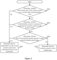
- Figure 3 is a schematic flow diagram of determining that a braking system is in a normal working state in a method for determining a real-time running speed of a train according to an embodiment of the present invention.
- step S103 of the above embodiment only the method of how to determine that the braking system is in a normal working state in step S103 of the above embodiment is described in detail.
- the other steps are substantially the same as those in the above embodiment, which are not repeated herein.
- the method may include the following steps S301 to S305.
- step S301 it is determined whether the braking system is in a preset failure state.
- step S302 it is determined whether an abnormality occurs in the target axle.
- This step is performed under the condition that a determination result in step S301 indicates that the braking system of the target train is not in the preset failure state.
- step S303 it is determined whether the braking system is in a normal data communication state.
- This step is performed under the condition that a determination result in step S302 indicates that no abnormality occurs in the target axle.
- step S304 it is determined that an abnormality occurs in the braking system and subsequent steps are not performed.
- This step is performed as long as not all the above three determination conditions are met. That is, the target axle is determined as abnormal, and axle speed information from the abnormal target axle is determined as unreliable. Therefore, the subsequent steps are required not to be performed.
- the three determination conditions are repeatedly determined until the three determination conditions are all met, and then the subsequent steps can be performed.
- step S305 it is determined that the braking system is in a normal state.
- This step is performed under the condition that a determination result in step S303 indicates that the braking system is in the normal data communication state. Hence based on the fact that the above three determination conditions are all met, it can be determined that the braking system is in the normal state, and the acquired axle speed of the target axle under this state is converted into the second real-time running speed by using a conversion formula in a subsequent step.
- Figure 4 is a schematic flow diagram of performing a speed correction by using a GPS in a method for determining a real-time running speed of a train according to an embodiment of the present invention.
- the method may include the following steps S401 to S403.
- step S401 a real-time running speed of the target train is measured by using the GPS to obtain a third real-time running speed.
- step S402 a ratio between the third real-time running speed and an effective real-time running speed is calculated to obtain a correction parameter.
- step S403 the effective real-time running speed is corrected by using the correction parameter.
- the ratio between the third real-time running speed and the effective real-time running speed is calculated as the correction parameter, to be used to correct the effective real-time running speed.
- the method for determining a real-time running speed of a train integrates a rotation speed of a traction motor obtained from a traction unit, an axle speed of a target axle obtained from a braking control unit, and a third real-time running speed of a train provided by the GPS and uses the above parameters from different sources to provide different schemes for different actual train running speeds.
- a more accurate real-time running speed of the train can be obtained, which facilitates subsequent intelligent control of the train.
- Figure 5 is a schematic structural block diagram of a system for determining a real-time train running speed according to an embodiment of the present invention.
- the determination system may include a parameter acquiring unit 100, a first running speed determining unit 200, a second running speed determining unit 300, an effective running speed determining unit 400 and a determination and correction unit 500.
- the parameter acquiring unit 100 is configured to acquire an axle speed of a target axle in a braking system and a rotation speed of a traction motor in a traction system in a target train.
- the first running speed determining unit 200 is configured to convert the rotation speed into a first real-time running speed by using a preset correspondence between a traction motor rotation speed and a train running speed in a case where the traction system is in a normal state.
- the second running speed determining unit 300 is configured to convert the axle speed into a second real-time running speed by using a preset correspondence between the axle speed and the train running speed in a case where the braking system is in a normal state.
- the effective running speed determining unit 400 is configured to determine the second real-time running speed as an effective real-time running speed of the target train in a case where both the traction system and the braking system are in the normal state.
- the determination and correction unit 500 is configured to determine whether the effective real-time running speed is greater than a preset running speed threshold and correct the effective real-time running speed by using a third real-time running speed measured by a global positioning system (GPS) in a case where the effective running speed is greater than the preset running speed threshold.
- GPS global positioning system
- the determination and correction unit 500 includes a GPS measuring sub-unit, a correction parameter calculating sub-unit and a correction sub-unit.
- the GPS measuring sub-unit is configured to measure the real-time running speed of the target train by using the GPS to obtain the third real-time running speed.
- the correction parameter calculating sub-unit is configured to calculate a ratio between the third real-time running speed and the effective real-time running speed to obtain a correction parameter.
- the correction sub-unit is configured to correct the effective real-time running speed by using the correction parameter.
- an apparatus for determining a real-time running speed of a train is further provided according to the present invention, which may include a memory and a processor.
- the memory stores computer programs.
- the processor when executing the computer programs in the memory, performs steps provided in the above embodiments.
- the apparatus may further include various required network interfaces, power source and other components.
- a computer readable storage medium is further provided according to the present invention.
- the computer readable storage medium stores computer programs. When the computer programs are performed by an executive terminal or a processor, the steps provided in the above embodiments are performed.
- the storage medium may include: a U-disk, a removable disk, a Read Only Memory (ROM), a Random Access Memory (RAM), a magnetic disk or a compact disk and other mediums that can store program codes.
Landscapes
- Engineering & Computer Science (AREA)
- Mechanical Engineering (AREA)
- Transportation (AREA)
- Physics & Mathematics (AREA)
- Automation & Control Theory (AREA)
- Mathematical Physics (AREA)
- Electric Propulsion And Braking For Vehicles (AREA)
Description
- The present application claims priority to
Chinese Patent Application No. 5 201711386165.7, titled "DETERMINING METHOD AND SYSTEM FOR REAL-TIME DRIVING SPEED OF TRAIN AND RELATED DEVICES", filed on December 20, 2017 - The present invention relates to the technical field of train network control, and in particular to a method, a system, and an apparatus for determining a real-time running speed of a train, and a computer readable storage medium.
- With rapid development of economy, science and technology, high speed railway trains have been widely used. During high-speed running, it is particularly important to accurately determine and monitor a real-time running speed of a train, which not only is beneficial to intelligent control of the train, but also has great significance for safe transportation.
- In an existing method for determining a real-time train speed, data that may reflect an actual running speed of a train is acquired only from a commonly used specific source, and then a conversion formula is used to obtain a real-time running speed of the train. However, due to the large quantity of devices in the train, the real-time running speed of the train derived from single-source data information is sometimes not reliable. Once the data source fails, the obtained real-time running speed of the train may be incorrect. Furthermore, due to the conversion, there may be a delay in speed feedback when the train runs at a high-speed. Thus, the existing methods for determining a real-time running speed of a train are not effective.
- Therefore, in order to overcome the technical deficiencies existing in the conventional methods for determining a real-time running speed of a train, it is desired to provide a method including a wide variety of data sources and appropriate adjustment at a high speed running state so as to accurately determine a real-time running speed of a train.
- In German Patent Application
DE 10 2013 210361 , a method for determining at least one speed in a rail vehicle is provided. A chassis speed measurement variable is provided by a sensor unit. Inertial measurement variables are detected by an inertial measurement unit; a reference speed characteristic value is formed; an inertial speed characteristic value is determined by a calculation unit based on the inertial measurement variables, in a first operating mode, to estimate a deviation in the inertial calculation based on the reference speed characteristic value; the inertial speed characteristic value is determined, in a second operating mode, without taking into account the reference speed characteristic value. - A method for determining a real-time running speed of a train is provided, which integrates a rotation speed of a traction motor obtained from a traction unit, an axle speed of a target axle obtained from a braking control unit, and a real-time running speed of a train provided by a GPS and uses the above parameters from different sources to provide different schemes for different actual train running speeds. By using the multiple sources of the parameters, and by eliminating a high-speed delay with a speed measured by a GPS in a high-speed running state, a more accurate real-time running speed of the train can be obtained, which facilitates subsequent intelligent control of the train.
- A system, an apparatus and a computer readable storage medium for determining a real-time running speed of a train are also provided.
- The method for determining a real-time running speed of a train provided according to the present invention includes the following steps. An axle speed of a target axle in a braking system and rotation speeds of one or more traction motors in a traction system in a target train are acquired. The rotation speeds are converted into a first real-time running speed by using a preset correspondence between a traction motor rotation speed and a train running speed in a case where the traction system is in a normal state. The axle speed is converted into a second real-time running speed by using a preset correspondence between the axle speed and the train running speed in a case where the braking system is in a normal state. The second real-time running speed is determined as an effective real-time running speed of the target train in a case where both the traction system and the braking system are in the normal state. It is determined whether the effective real-time running speed is greater than a preset running speed threshold, a third real-time running speed measured by a GPS is utilized to correct the effective real-time running speed in a case where the effective running speed is greater than the preset running speed threshold.
- In an embodiment, the traction system is determined to be in the normal state by the method including: determining whether each of traction units in the traction system is in a normal data communication state; determining whether an abnormality occurs in a process of acquiring the rotation speeds of the one or more traction motors in a case where each of the traction units is in the normal data communication state; determining whether any one of acquired rotation speeds exceeds a preset rotation speed range in a case where no abnormality occurs in the process of acquiring the rotation speeds of the one or more traction motors; determining that the traction system is in the normal state in a case where none of the acquired rotation speeds exceeds the preset rotation speed range.
- In an embodiment, the braking system is determined to be in the normal state by the method including: determining whether the braking system is in a preset failure state; determining whether an abnormality occurs in the target axle in a case where the braking system is not in the preset failure state; determining whether the braking system is in a normal data communication state in a case where no abnormality occurs in the target axle; determining that the braking system is in the normal state in a case where the braking system is in the normal data communication state.
- In an embodiment, in a case where the target train comprises a plurality of traction systems, the method further includes: acquiring rotation speeds of one or more traction motors in all of the traction systems; obtaining temporary values of the first real-time running speeds by converting the rotation speeds by using the preset correspondence between the traction motor rotation speed and the train running speed; averaging all the temporary values of the first real-time running speed to obtain the first real-time running speed.
- In an embodiment, the method further includes: determining the first real-time running speed as the effective real-time running speed in a case where an abnormality occurs in the braking system and the traction system is in the normal state.
- In an embodiment, the correcting the effective real-time running speed by using a third real-time running speed measured by a GPS includes: measuring the real-time running speed of the target train by using the GPS to obtain the third real-time running speed; calculating a ratio between the third real-time running speed and the effective real-time running speed to obtain a correction parameter; and correcting the effective real-time running speed by using the correction parameter.
- The system for determining a real-time running speed of a train provided according to the present invention includes: a parameter acquiring unit, a first running speed determining unit, a second running speed determining unit, an effective running speed determining unit and a determination and correction unit. The parameter acquiring unit is configured to acquire an axle speed of a target axle in a braking system and a rotation speed of a traction motor in a traction system in a target train. The first running speed determining unit is configured to convert the rotation speed into a first real-time running speed by using a preset correspondence between a traction motor rotation speed and a train running speed in a case where the traction system is in a normal state. The second running speed determining unit is configured to convert the axle speed into a second real-time running speed by using a preset correspondence between the axle speed and the train running speed in a case where the braking system is in the normal state. The effective running speed determining unit is configured to determine the second real-time running speed as an effective real-time running speed of the target train in a case where both the traction system and the braking system are in the normal state. The determination and correction unit is configured to determine whether the effective real-time running speed is greater than a preset running speed threshold and correct the effective real-time running speed by using a third real-time running speed measured by a GPS in a case where the effective running speed is greater than the preset running speed threshold.
- In an embodiment, the determination and correction unit includes: a GPS measuring sub-unit, a correction parameter calculating sub-unit and a correction sub-unit. The GPS measuring sub-unit is configured to measure the real-time running speed of the target train by using the GPS to obtain the third real-time running speed. The correction parameter calculating sub-unit is configured to calculate a ratio between the third real-time running speed and the effective real-time running speed to obtain a correction parameter. The correction sub-unit is configured to correct the effective real-time running speed by using the correction parameter.
- The apparatus for determining a real-time running speed of a train provided according to the present invention includes: a storage medium and a processor. The storage medium is configured to store computer programs. The processor is configured to perform steps of the above method for determining a real-time running speed of a train when executing the computer programs.
- The computer readable storage medium provided according to the present invention stores computer programs. The computer program, when executed by a processor, causes the processor to perform the method for determining a real-time running speed of a train.
- In the method for determining a real-time running speed of a train, an axle speed of a target axle in a braking system and a rotation speed of a traction motor in a traction system in a target train are acquired. The rotation speed is converted into a first real-time running speed by using a preset correspondence between a traction motor rotation speed and a train running speed in a case where the traction system is in a normal state. The axle speed is converted into a second real-time running speed by using a preset correspondence between the axle speed and the train running speed in a case where the braking system is in the normal state. The second real-time running speed is determined as an effective real-time running speed of the target train in a case where both the traction system and the braking system are in the normal state. It is determined whether the effective real-time running speed is greater than a preset running speed threshold. A third real-time running speed measured by a GPS is utilized to correct the effective real-time running speed in a case where the effective running speed is greater than the preset running speed threshold.
- Apparently, the technical solution provided according to the present invention integrates a rotation speed of a traction motor obtained from a traction unit, an axle speed of a target axle obtained from a braking control unit, and a real-time running speed of the train provided by a GPS and uses the above parameters from different sources to provide different schemes for different actual train running speeds. By using the multiple sources of the parameters, and by eliminating a high-speed delay with a speed measured by a GPS in a high-speed running state, a more accurate real-time running speed of the train can be obtained, which facilitate subsequent intelligent control of the train. A determination system and an apparatus for determining a real-time running speed of a train and a computer readable storage medium are further provided according to the present invention, which have the above beneficial effects and are not repeated herein.
- In order to more clearly illustrate technical solutions of the embodiments of the present invention or the conventional technology, the drawings required in the description of the embodiments or the conventional technology are briefly described below. Apparently, the drawings are only some embodiments of the present invention, and other drawings may be acquired by those skilled in the art based on the drawings provided herein without any creative work.
-
Figure 1 is a schematic flow diagram of a method for determining a real-time running speed of a train according to an embodiment of the present invention; -
Figure 2 is a schematic flow diagram of determining that a traction system is in a normal state in a method for determining a real-time running speed of a train according to an embodiment of the present invention; -
Figure 3 is a schematic flow diagram of determining that a braking system is in a normal state in a method for determining a real-time running speed of a train according to an embodiment of the present invention; -
Figure 4 is a schematic flow diagram of correcting a speed by using a GPS in a method for determining a real-time running speed of a train according to an embodiment of the present invention; and -
Figure 5 is a schematic structural block diagram of a system for determining a real-time running speed of a train according to an embodiment of the present invention. - A method, a system, and an apparatus for determining a real-time running speed of a train and a computer readable storage medium are provided in the present invention, which integrates a rotation speed of a traction motor obtained from a traction unit, an axle speed of a target axle obtained from a braking control unit, and a real-time running speed of a train provided by a GPS and uses the above parameters from different sources to provide different schemes for different actual train running speeds. By using the multiple sources of the parameters, and by eliminating a high-speed delay with a speed measured by a GPS in a high-speed running state, a more accurate real-time running speed of the train can be obtained, which facilitates subsequent intelligent control of the train.
- In order to make the purpose, technical solution and advantages of the embodiment of the present invention clearer, hereinafter, the technical solutions according to the embodiments of the present invention will be described clearly and completely in conjunction with the drawings. Apparently, the described embodiments are only a few rather than all of embodiments of the present invention. Any other embodiments obtained by those skilled in the art based on the embodiments of the present invention without any creative work fall within the scope of protection of the invention, as defined by the appended claims.
- Reference is made to
Figure 1 , which is a schematic flow diagram of a method for determining a real-time running speed of a train according to an embodiment of the present invention. - The method includes the following steps S101 to S 107.
- In step S101, an axle speed of a target axle in a braking system and a rotation speed of a traction motor in a traction system in a target train are acquired.
- The braking system is responsible for controlling braking of the train, and thus it monitors the axle speed of each of the train axles. The target axle is a representative axle selected from all the train axles. A real-time running speed of the train converted from the axle speed of the target axle can best reflect a true real-time running speed, and thus it is used with a highest priority. The traction system provides traction for the target train, the most important part of which is the traction motor. In the embodiment, the rotation speed of the traction motor acquired from the traction system is also utilized to calculate the real-time running speed of the train.
- There may be different numbers of traction systems in trains of different types and formations. Each traction system may include different numbers of traction motors. In a case that only one traction system exists and is in a normal operation state and only one traction motor is included in the traction system during the actual operation of the train, the rotation speed of the only traction motor is required to be obtained. The target axle is determined from all the train axles in the braking system based on a preset selection rule, and the axle speed is obtained by using a corresponding axle speed sensor. For example, in a multiple-unit train with eight carriages, an axle 3 in train axles of a locomotive may be selected as the target axle, and the axle speed of the target axle is required to be obtained.
- Apparently, in the case of multiple traction systems or multiple traction motors in a traction system, there is a variety of ways to process multiple rotation speeds to obtain a representative speed. Only as a redundant design, for example, when a rotation speed of a traction motor in a traction system is unavailable, another rotation speeds may be obtained for subsequent processing and other processing such as averaging may also be performed to meet some special requirements. The selection rules of the target axle may also be changed according to the actual situation, which is not limited herein and may be flexibly selected based on the actual conditions.
- In step S102, the rotation speed is converted into a first real-time running speed by using a preset correspondence between a traction motor rotation speed and a train running speed in a case where the traction system is in a normal state.
- Based on step S101, in this step, the rotation speed is converted into a first real-time running speed by using a preset correspondence between a traction motor rotation speed and a train running speed in a case where the traction system is in a normal state. Apparently, in a case of multiple traction systems in the target train, this step may be changed as follows for example. The rotation speed of the traction motor in each of the traction systems is acquired. A corresponding numbers of temporary values of the first real-time running speed are obtained by converting the rotation speeds by using the preset correspondence between the traction motor rotation speed and the train running speed. Then an average of the temporary values of the first real-time running speed is calculated to obtain the first real-time running speed.
- The preset correspondence between the traction motor rotation speed and the train running speed has been well known by those skilled in the art and may be different depending on different actual conditions, such as train types, working conditions and other influencing factors, which is not described herein.
- In step S103, the axle speed is converted into a second real-time running speed by using a preset correspondence between the axle speed and the train running speed in a case where the braking system is in a normal state.
- Based on step S101, in this step, the axle speed is converted into a second real-time running speed by using a preset correspondence between the axle speed and the train running speed in a case where the braking system is in a normal state. The normal states of the traction system and the braking system in steps S 102 and S103 are used to indicate that the actual working state of the traction motor and the target axle is normal and thus the rotation speed of the traction motor and the axle speed of the train axle obtained in this case are reliable and valid. The method for determining whether the traction system and the braking system are in the normal states is described in detail in the following embodiments.
- In step S104, the second real-time running speed is determined as an effective real-time running speed of the target train in a case where both the traction system and the braking system are in the normal state.
- Based on steps S102 and S103, in this step, the second real-time running speed is determined as an effective real-time running speed of the target train in a case where both the traction system and the braking system are in the normal state. The reason for discarding the first real-time running speed converted from the rotation speed of the traction motor in the traction system and using the second real-time running speed converted from the axle speed of the target axle in the braking system is that the target axle in the train braking system is connected with wheels that actually drives the train, and thus it can most truly reflect the actual running speed of the target train.
- Apparently, this step is performed under the condition that the braking system is in the normal state. If an abnormality occurs in the braking system, which indicates that the axle speed of the target axle cannot be fed back or the feedback axle speed is not reliable, the first real-time running speed, as a reliable real-time running speed in this case, may be determined as the effective real-time running speed.
- In step S105, it is determined whether the effective real-time running speed is greater than a preset running speed threshold.
- Based on step S104, in this step, it is determined whether the effective real-time running speed is greater than a preset running speed threshold. Since a delay of the feedback of the running speed may occur when the train is in a high-speed running state, a least speed which may cause the delay is used as a speed threshold, to be compared with the effective real-time running speed.
- In step S106, the effective real-time running speed is determined as an actual real-time running speed of the train.
- This step is performed if a determination result in
S 105 indicates that the effective running speed is less than the preset running speed threshold. That is, if a speed critical point at which the delay may occur is not yet reached, the effective real-time running speed may be directly determined as the actual real-time running speed of the train. - In step S107, the effective real-time running speed is corrected by using a third real-time running speed measured by a GPS.
- This step is performed if the determination result in
S 105 indicates that the effective running speed is greater than the preset running speed threshold. That is, if the speed critical point at which the delay may occur is reached, the third real-time running speed measured by the GPS is utilized to correct the effective real-time running speed. - Since the ultimate purpose is to obtain the accurate real-time running speed of the train based on the feedback from the train, the real-time running speed measured by the GPS, instead of directly being used, is only used to correct the effective real-time running speed.
- There are various ways to correct the effective real-time running speed. For example, a difference or a ratio of the two is determined as a parameter for correction, which is not limited herein. An appropriate correction method may be chosen based on the actual situation.
- From the above technical solution, it can be seen that the method for determining a real-time running speed of a train provided in the embodiment of the present invention integrates a rotation speed of a traction motor obtained from a traction unit, an axle speed of a target axle obtained from a braking control unit, and a real-time running speed of the train provided by the GPS and uses the above parameters from different sources to provide different schemes for different actual train running speeds. By using the multiple sources of the parameters, and by eliminating a high-speed delay with a speed measured by a GPS in a high-speed running state, a more accurate real-time running speed of the train can be obtained, which facilitates subsequent intelligent control of the train.
- Reference is made to
Figure 2 , which is a schematic flow diagram of determining that a traction system is in a normal working state in a method for determining a real-time running speed of a train according to an embodiment of the present invention. - In this embodiment, only the method of how to determine that the traction system is in a normal working state in step S102 of the above embodiment is described in detail. The other steps are substantially the same as those in the above embodiment, which are not repeated herein.
- The method may include the following steps S201 to S205.
- In step S201, it is determined whether each of traction units in the traction system is in a normal data communication state.
- In step S202, it is determined whether an abnormality occurs in a process of acquiring the rotation speeds of all the traction motor.
- This step is performed under the condition that a determination result in step S201 indicates that each of the traction units is in the normal data communication state.
- In step S203, it is determined whether any of acquired rotation speeds exceeds a preset rotation speed range.
- This step is performed under the condition that a determination result in step S202 indicates that no abnormality occurs in the process of acquiring the rotation speeds of all the traction motors.
- In step S204, it is determined that an abnormality occurs in the traction system and subsequent steps are not performed.
- This step is performed as long as not all the above three determination conditions are met. That is, the traction system is determined as abnormal, and rotation speed information of the traction motor in the abnormal traction system is determined as unreliable. Therefore, the subsequent steps are required not to be performed. The three determination conditions are repeatedly determined until the three determination conditions are all met, and then the subsequent steps can be performed.
- In step S205, it is determined that the traction system is in a normal state.
- This step is performed under the condition that a determination result in step S203 indicates that none of the acquired rotation speeds exceeds the preset rotation speed range. Hence based on the fact that the above three determination conditions are all met, it can be determined that the traction system is in the normal state, and the rotation speed of the traction motor under this state is converted into the first real-time running speed by using a conversion formula in a subsequent step.
- Reference is made to
Figure 3 , which is a schematic flow diagram of determining that a braking system is in a normal working state in a method for determining a real-time running speed of a train according to an embodiment of the present invention. - In this embodiment, only the method of how to determine that the braking system is in a normal working state in step S103 of the above embodiment is described in detail. The other steps are substantially the same as those in the above embodiment, which are not repeated herein.
- The method may include the following steps S301 to S305.
- In step S301, it is determined whether the braking system is in a preset failure state.
- In step S302, it is determined whether an abnormality occurs in the target axle.
- This step is performed under the condition that a determination result in step S301 indicates that the braking system of the target train is not in the preset failure state.
- In step S303, it is determined whether the braking system is in a normal data communication state.
- This step is performed under the condition that a determination result in step S302 indicates that no abnormality occurs in the target axle.
- In step S304, it is determined that an abnormality occurs in the braking system and subsequent steps are not performed.
- This step is performed as long as not all the above three determination conditions are met. That is, the target axle is determined as abnormal, and axle speed information from the abnormal target axle is determined as unreliable. Therefore, the subsequent steps are required not to be performed. The three determination conditions are repeatedly determined until the three determination conditions are all met, and then the subsequent steps can be performed.
- In step S305, it is determined that the braking system is in a normal state.
- This step is performed under the condition that a determination result in step S303 indicates that the braking system is in the normal data communication state. Hence based on the fact that the above three determination conditions are all met, it can be determined that the braking system is in the normal state, and the acquired axle speed of the target axle under this state is converted into the second real-time running speed by using a conversion formula in a subsequent step.
- Reference is made to
Figure 4 , which is a schematic flow diagram of performing a speed correction by using a GPS in a method for determining a real-time running speed of a train according to an embodiment of the present invention. - In this embodiment, only the method of how to perform speed correction by using the GPS in step S107 of the above embodiment is described in detail. The other steps are substantially the same as those in the above embodiment, which are not repeated herein.
- The method may include the following steps S401 to S403.
- In step S401, a real-time running speed of the target train is measured by using the GPS to obtain a third real-time running speed.
- In step S402, a ratio between the third real-time running speed and an effective real-time running speed is calculated to obtain a correction parameter.
- In step S403, the effective real-time running speed is corrected by using the correction parameter.
- In this embodiment, the ratio between the third real-time running speed and the effective real-time running speed is calculated as the correction parameter, to be used to correct the effective real-time running speed.
- From the above technical solution, it can be seen that the method for determining a real-time running speed of a train provided in the embodiment of the present invention integrates a rotation speed of a traction motor obtained from a traction unit, an axle speed of a target axle obtained from a braking control unit, and a third real-time running speed of a train provided by the GPS and uses the above parameters from different sources to provide different schemes for different actual train running speeds. By using the multiple sources of the parameters, and by eliminating a high-speed delay with a speed measured by a GPS in a high-speed running state, a more accurate real-time running speed of the train can be obtained, which facilitates subsequent intelligent control of the train.
- Due to complicated situations, the embodiments cannot be enumerated. Those skilled in the art should realize that any embodiments obtained based on a basic principle provided in the present invention in conjunction with actual situations without any creative work fall within the scope of protection of the invention.
- Reference is made to
Figure 5 , which is a schematic structural block diagram of a system for determining a real-time train running speed according to an embodiment of the present invention. - The determination system may include a
parameter acquiring unit 100, a first runningspeed determining unit 200, a second runningspeed determining unit 300, an effective runningspeed determining unit 400 and a determination andcorrection unit 500. - The
parameter acquiring unit 100 is configured to acquire an axle speed of a target axle in a braking system and a rotation speed of a traction motor in a traction system in a target train. - The first running
speed determining unit 200 is configured to convert the rotation speed into a first real-time running speed by using a preset correspondence between a traction motor rotation speed and a train running speed in a case where the traction system is in a normal state. - The second running
speed determining unit 300 is configured to convert the axle speed into a second real-time running speed by using a preset correspondence between the axle speed and the train running speed in a case where the braking system is in a normal state. - The effective running
speed determining unit 400 is configured to determine the second real-time running speed as an effective real-time running speed of the target train in a case where both the traction system and the braking system are in the normal state. - The determination and
correction unit 500 is configured to determine whether the effective real-time running speed is greater than a preset running speed threshold and correct the effective real-time running speed by using a third real-time running speed measured by a global positioning system (GPS) in a case where the effective running speed is greater than the preset running speed threshold. - The determination and
correction unit 500 includes a GPS measuring sub-unit, a correction parameter calculating sub-unit and a correction sub-unit. - The GPS measuring sub-unit is configured to measure the real-time running speed of the target train by using the GPS to obtain the third real-time running speed.
- The correction parameter calculating sub-unit is configured to calculate a ratio between the third real-time running speed and the effective real-time running speed to obtain a correction parameter.
- The correction sub-unit is configured to correct the effective real-time running speed by using the correction parameter.
- Based on the above embodiments, an apparatus for determining a real-time running speed of a train is further provided according to the present invention, which may include a memory and a processor. The memory stores computer programs. The processor, when executing the computer programs in the memory, performs steps provided in the above embodiments. Apparently, the apparatus may further include various required network interfaces, power source and other components.
- A computer readable storage medium is further provided according to the present invention. The computer readable storage medium stores computer programs. When the computer programs are performed by an executive terminal or a processor, the steps provided in the above embodiments are performed. The storage medium may include: a U-disk, a removable disk, a Read Only Memory (ROM), a Random Access Memory (RAM), a magnetic disk or a compact disk and other mediums that can store program codes.
- It should be noted that the embodiments in the specification are described in a progressive manner, with the emphasis of each of the embodiments on the difference from other embodiments. For the same or similar parts between the embodiments, reference may be made one to another. Since the device disclosed in the embodiments corresponds to the method disclosed in the embodiment, the description for the device is simple, and reference may be made to the method embodiment for the relevant parts.
- Those skilled in the art can further realize that the units and the algorithm steps of the examples described in conjunction with the embodiments disclosed herein, may be implemented by electronic hardware, computer software, or a combination thereof. To illustrate interchangeability between the hardware and the software clearly, the composition and the steps of each of the examples are generally described according to functions in the above illustration. Whether the functions being performed by hardware or software depends on a specific application and a design constraint condition of the technical solution. Those skilled in the art can implement the described functions using different methods for each of the specific applications, as far as the implementation fall within the scope of the present invention, as defined by the appended claims.
Claims (10)
- A method for determining a real-time running speed of a train, comprising:acquiring (S101) an axle speed of a target axle in a braking system and rotation speeds of one or more traction motors in a traction system in a target train;converting (S102) the rotation speeds into a first real-time running speed by using a preset correspondence between a traction motor rotation speed and a train running speed if determining that the traction system is in a normal state;converting (S103) the axle speed into a second real-time running speed by using a preset correspondence between the axle speed and the train running speed if determining that the braking system is in a normal state;determining (S104) the second real-time running speed as an effective real-time running speed of the target train in a case where both the traction system and the braking system are in the normal state; anddetermining (S105) whether the effective real-time running speed is greater than a preset running speed threshold, and correcting the effective real-time running speed by using a third real-time running speed measured by a global positioning system, GPS, in a case where the effective running speed is greater than the preset running speed threshold.
- The method according to claim 1, wherein the determining that the traction system is in a normal state comprises:determining (S201) whether each of traction units in the traction system is in a normal data communication state;determining (S202) whether an abnormality occurs in a process of acquiring the rotation speeds of the one or more traction motors in a case where each of the traction units in the traction system is in the normal data communication state;determining (S203) whether any one of acquired rotation speeds exceeds a preset rotation speed range in a case where no abnormality occurs in the process of acquiring the rotation speeds of the one or more traction motors; anddetermining (S205) that the traction system is in the normal state in a case where none of the acquired rotation speeds exceeds the preset rotation speed range.
- The method according to claim 2, wherein the determining (S205) that the braking system is in a normal state comprises:determining (S301) whether the braking system is in a preset failure state;determining (S302) whether an abnormality occurs in the target axle in a case where the braking system is not in the preset failure state;determining (S303) whether the braking system is in a normal data communication state in a case where no abnormality occurs in the target axle; anddetermining (S305) that the braking system is in the normal state in a case where the braking system is in the normal data communication state.
- The method according to any one of claims 1 to 3, wherein in a case where the target train comprises a plurality of traction systems, the method further comprises:acquiring rotation speeds of one or more traction motors in all of the plurality of traction systems;obtaining temporary values of the first real-time running speed by converting the rotation speeds using the preset correspondence between the traction motor rotation speed and the train running speed; andaveraging all the temporary values of the first real-time running speed to obtain the first real-time running speed.
- The method according to claim 4, further comprising:
determining the first real-time running speed as the effective real-time running speed in a case where an abnormality occurs in the braking system and the traction state is in the normal state. - The method according to claim 5, wherein the correcting the effective real-time running speed by using a third real-time running speed measured by a GPS comprises:measuring (S401) the real-time running speed of the target train by using the GPS to obtain the third real-time running speed;calculating (S402) a ratio between the third real-time running speed and the effective real-time running speed to obtain a correction parameter; andcorrecting (S403) the effective real-time running speed by using the correction parameter.
- A system for determining a real-time running speed of a train, comprising:a parameter acquiring unit (100), configured to acquire an axle speed of a target axle in a braking system and a rotation speed of a traction motor in a traction system in a target train;a first running speed determining unit (200), configured to convert the rotation speed into a first real-time running speed by using a preset correspondence between a traction motor rotation speed and a train running speed in a case where the traction system is in a normal state;a second running speed determining unit (300), configured to convert the axle speed into a second real-time running speed by using a preset correspondence between the axle speed and the train running speed in a case where the braking system is in a normal state;an effective running speed determining unit (400), configured to determine the second real-time running speed as an effective real-time running speed of the target train in a case where both the traction system and the braking system are in the normal state; anda determination and correction unit (500), configured to determine whether the effective real-time running speed is greater than a preset running speed threshold and correct the effective real-time running speed by using a third real-time running speed measured by a global positioning system, GPS, in a case where the effective running speed is greater than the preset running speed threshold.
- The system according to claim 7, wherein the determination and correction unit (500) comprises:a GPS measuring sub-unit, configured to measure the real-time running speed of the target train by using the GPS to obtain the third real-time running speed;a correction parameter calculating sub-unit, configured to calculate a ratio between the third real-time running speed and the effective real-time running speed to obtain a correction parameter; anda correction sub-unit, configured to correct the effective real-time running speed by using the correction parameter.
- A computer readable storage medium, storing computer programs, wherein the computer program, when executed by a processor, causes the processor to perform the method for determining a real-time running speed of a train according to any one of claims 1 to 6.
- An apparatus for determining a real-time running speed of a train, comprising:a storage medium, configured to store computer programs, according to claim 9,a processor, configured to perform steps of the method for determining a real-time running speed of a train described according to any of claims 1 to 6 when executing the computer programs.
Priority Applications (1)
| Application Number | Priority Date | Filing Date | Title |
|---|---|---|---|
| RS20231256A RS64999B1 (en) | 2017-12-20 | 2017-12-28 | Determining method and system for real-time driving speed of train and related devices |
Applications Claiming Priority (2)
| Application Number | Priority Date | Filing Date | Title |
|---|---|---|---|
| CN201711386165.7A CN109318946A (en) | 2017-12-20 | 2017-12-20 | A kind of determination method, system and the relevant apparatus of train real time running speed |
| PCT/CN2017/119204 WO2019119494A1 (en) | 2017-12-20 | 2017-12-28 | Determining method and system for real-time driving speed of train and related devices |
Publications (3)
| Publication Number | Publication Date |
|---|---|
| EP3731442A1 EP3731442A1 (en) | 2020-10-28 |
| EP3731442A4 EP3731442A4 (en) | 2021-08-18 |
| EP3731442B1 true EP3731442B1 (en) | 2023-10-25 |
Family
ID=65246087
Family Applications (1)
| Application Number | Title | Priority Date | Filing Date |
|---|---|---|---|
| EP17935459.2A Active EP3731442B1 (en) | 2017-12-20 | 2017-12-28 | Determining method and system for real-time driving speed of train and related devices |
Country Status (6)
| Country | Link |
|---|---|
| EP (1) | EP3731442B1 (en) |
| CN (1) | CN109318946A (en) |
| HU (1) | HUE064233T2 (en) |
| MY (1) | MY196231A (en) |
| RS (1) | RS64999B1 (en) |
| WO (1) | WO2019119494A1 (en) |
Families Citing this family (5)
| Publication number | Priority date | Publication date | Assignee | Title |
|---|---|---|---|---|
| CN113581254B (en) * | 2020-04-30 | 2022-12-09 | 比亚迪股份有限公司 | Train speed determination method, device, computer equipment and readable storage medium |
| CN113156156B (en) * | 2021-03-31 | 2022-09-30 | 中车青岛四方车辆研究所有限公司 | Speed processing method of multi-speed sensor system for train |
| CN113098520A (en) * | 2021-04-02 | 2021-07-09 | 湖南中车时代通信信号有限公司 | Digital-to-analog conversion device, display control method and electronic equipment for train speed per hour |
| CN113715877B (en) * | 2021-09-16 | 2022-09-02 | 交控科技股份有限公司 | Train control method, system, computer device and storage medium |
| CN114954572B (en) * | 2022-06-14 | 2024-04-19 | 通号城市轨道交通技术有限公司 | Automatic train dispatching method and device based on traction energy consumption statistics |
Family Cites Families (11)
| Publication number | Priority date | Publication date | Assignee | Title |
|---|---|---|---|---|
| DE3639416C1 (en) * | 1986-11-18 | 1987-11-19 | Licentia Gmbh | Method for determining the real speed of a train |
| JP3006273B2 (en) * | 1992-03-06 | 2000-02-07 | トヨタ自動車株式会社 | Vehicle motion control device |
| US9102309B2 (en) * | 2006-08-25 | 2015-08-11 | Railpower, Llc | System and method for detecting wheel slip and skid in a locomotive |
| CN100503333C (en) * | 2007-01-16 | 2009-06-24 | 重庆大学 | Multipoint location system for rail vehicle go and back running |
| CN102387556B (en) * | 2011-10-18 | 2014-01-29 | 西南交通大学 | Inter-cell handover method of train-ground communication based on cooperative multipoint transmission in high-speed mobile environment |
| DE102013210361A1 (en) * | 2013-06-04 | 2014-12-04 | Siemens Aktiengesellschaft | Method for determining at least one speed in a rail vehicle |
| DE102014226612B4 (en) * | 2014-12-19 | 2021-05-20 | Deutsches Zentrum für Luft- und Raumfahrt e.V. | Method for determining the speed of a rail vehicle |
| US9463817B2 (en) * | 2015-02-16 | 2016-10-11 | Electro-Motive Diesel, Inc. | Automatic disabling of unpowered locked wheel fault detection for slipped traction motor pinion |
| CN105059325B (en) * | 2015-07-31 | 2017-03-08 | 株洲中车时代电气股份有限公司 | A kind of locomotive localization method and system |
| CN106100788A (en) * | 2016-06-07 | 2016-11-09 | 天脉聚源(北京)传媒科技有限公司 | A kind of high ferro audiovisual data transmission method and device |
| CN106627673A (en) * | 2016-10-27 | 2017-05-10 | 交控科技股份有限公司 | Multi-sensor fusion train positioning method and system |
-
2017
- 2017-12-20 CN CN201711386165.7A patent/CN109318946A/en active Pending
- 2017-12-28 EP EP17935459.2A patent/EP3731442B1/en active Active
- 2017-12-28 HU HUE17935459A patent/HUE064233T2/en unknown
- 2017-12-28 WO PCT/CN2017/119204 patent/WO2019119494A1/en active Application Filing
- 2017-12-28 RS RS20231256A patent/RS64999B1/en unknown
-
2018
- 2018-07-26 MY MYPI2018702615A patent/MY196231A/en unknown
Also Published As
| Publication number | Publication date |
|---|---|
| RS64999B1 (en) | 2024-01-31 |
| CN109318946A (en) | 2019-02-12 |
| MY196231A (en) | 2023-03-24 |
| EP3731442A1 (en) | 2020-10-28 |
| HUE064233T2 (en) | 2024-02-28 |
| EP3731442A4 (en) | 2021-08-18 |
| WO2019119494A1 (en) | 2019-06-27 |
Similar Documents
| Publication | Publication Date | Title |
|---|---|---|
| EP3731442B1 (en) | Determining method and system for real-time driving speed of train and related devices | |
| AU2015357939B2 (en) | Method, device, and system for controlling wind alignment correction of wind turbine generator system | |
| US20210269087A1 (en) | Active Fault Tolerance and Fault Mitigation System Based on Steer-by-wire with Dual Motors and Control Method Therefor | |
| CN103048012B (en) | Zero point correcting method and system for sine and cosine encoders as well as elevator | |
| CN103097213B (en) | Determination of steering angle for a motor vehicle | |
| EP4015334A1 (en) | Slope calculation method and device | |
| CN109050576A (en) | A kind of wheel footpath modification method, device, equipment and readable storage medium storing program for executing | |
| CN105015561A (en) | Adhesion control system for motor train unit | |
| CN105270393B (en) | Torque error detection and torque estimation system | |
| CN208842355U (en) | A kind of vehicle speed signal processing system of multisignal source fusion | |
| CN113581288A (en) | Automatic driving lateral deviation dynamic correction method, device, equipment and storage medium | |
| CN111697900A (en) | Oil-gas pump motor control method and device | |
| US10554159B2 (en) | Monitoring and compensating the angle of a rotor in an electric machine using an angle sensor | |
| CN116373955A (en) | Dynamic compensation method and system for errors of train traction braking model | |
| KR102213198B1 (en) | Vehicle controller with sensor data automatic detection function and sensor data automatic detection method thereof | |
| US11287800B2 (en) | Method for monitoring machine, device, and storage medium | |
| CN112904431B (en) | Method, device and system for detecting non-induction plate area of vehicle of linear motor traction system and medium | |
| CN114103951B (en) | Parameter determination method and related device | |
| CN113753024B (en) | Method, device, equipment and storage medium for eliminating steady-state deviation of vehicle | |
| CN114157211B (en) | Real-time correction method and system for rotary zero position of driving motor for vehicle | |
| CN113353108B (en) | Vehicle backward running protection method and related device | |
| CN116408745A (en) | Wireless control's intelligent torque wrench | |
| CN115027533B (en) | Rail train speed and distance measuring method and device | |
| CN116729407B (en) | Vehicle lateral speed detection method, electronic device, and storage medium | |
| CN112083648A (en) | PID-based train constant speed control method, device, medium and equipment |
Legal Events
| Date | Code | Title | Description |
|---|---|---|---|
| STAA | Information on the status of an ep patent application or granted ep patent |
Free format text: STATUS: THE INTERNATIONAL PUBLICATION HAS BEEN MADE |
|
| PUAI | Public reference made under article 153(3) epc to a published international application that has entered the european phase |
Free format text: ORIGINAL CODE: 0009012 |
|
| STAA | Information on the status of an ep patent application or granted ep patent |
Free format text: STATUS: REQUEST FOR EXAMINATION WAS MADE |
|
| 17P | Request for examination filed |
Effective date: 20191203 |
|
| AK | Designated contracting states |
Kind code of ref document: A1 Designated state(s): AL AT BE BG CH CY CZ DE DK EE ES FI FR GB GR HR HU IE IS IT LI LT LU LV MC MK MT NL NO PL PT RO RS SE SI SK SM TR |
|
| AX | Request for extension of the european patent |
Extension state: BA ME |
|
| DAV | Request for validation of the european patent (deleted) | ||
| DAX | Request for extension of the european patent (deleted) | ||
| A4 | Supplementary search report drawn up and despatched |
Effective date: 20210716 |
|
| RIC1 | Information provided on ipc code assigned before grant |
Ipc: H04L 1/00 20060101AFI20210712BHEP Ipc: B60T 8/172 20060101ALI20210712BHEP Ipc: B60W 40/105 20120101ALI20210712BHEP Ipc: B60T 8/17 20060101ALI20210712BHEP Ipc: B61L 25/02 20060101ALI20210712BHEP |
|
| GRAP | Despatch of communication of intention to grant a patent |
Free format text: ORIGINAL CODE: EPIDOSNIGR1 |
|
| STAA | Information on the status of an ep patent application or granted ep patent |
Free format text: STATUS: GRANT OF PATENT IS INTENDED |
|
| RIC1 | Information provided on ipc code assigned before grant |
Ipc: B61L 25/02 20060101ALI20221027BHEP Ipc: B60T 8/17 20060101ALI20221027BHEP Ipc: B60W 40/105 20120101ALI20221027BHEP Ipc: B60T 8/172 20060101ALI20221027BHEP Ipc: H04L 1/00 20060101AFI20221027BHEP |
|
| INTG | Intention to grant announced |
Effective date: 20221129 |
|
| GRAJ | Information related to disapproval of communication of intention to grant by the applicant or resumption of examination proceedings by the epo deleted |
Free format text: ORIGINAL CODE: EPIDOSDIGR1 |
|
| STAA | Information on the status of an ep patent application or granted ep patent |
Free format text: STATUS: REQUEST FOR EXAMINATION WAS MADE |
|
| INTC | Intention to grant announced (deleted) | ||
| GRAP | Despatch of communication of intention to grant a patent |
Free format text: ORIGINAL CODE: EPIDOSNIGR1 |
|
| STAA | Information on the status of an ep patent application or granted ep patent |
Free format text: STATUS: GRANT OF PATENT IS INTENDED |
|
| INTG | Intention to grant announced |
Effective date: 20230517 |
|
| GRAS | Grant fee paid |
Free format text: ORIGINAL CODE: EPIDOSNIGR3 |
|
| GRAA | (expected) grant |
Free format text: ORIGINAL CODE: 0009210 |
|
| STAA | Information on the status of an ep patent application or granted ep patent |
Free format text: STATUS: THE PATENT HAS BEEN GRANTED |
|
| AK | Designated contracting states |
Kind code of ref document: B1 Designated state(s): AL AT BE BG CH CY CZ DE DK EE ES FI FR GB GR HR HU IE IS IT LI LT LU LV MC MK MT NL NO PL PT RO RS SE SI SK SM TR |
|
| REG | Reference to a national code |
Ref country code: GB Ref legal event code: FG4D |
|
| REG | Reference to a national code |
Ref country code: CH Ref legal event code: EP |
|
| REG | Reference to a national code |
Ref country code: DE Ref legal event code: R096 Ref document number: 602017075874 Country of ref document: DE |
|
| REG | Reference to a national code |
Ref country code: IE Ref legal event code: FG4D |
|
| PGFP | Annual fee paid to national office [announced via postgrant information from national office to epo] |
Ref country code: RS Payment date: 20231228 Year of fee payment: 7 |
|
| REG | Reference to a national code |
Ref country code: LT Ref legal event code: MG9D |
|
| REG | Reference to a national code |
Ref country code: NL Ref legal event code: MP Effective date: 20231025 Ref country code: HU Ref legal event code: AG4A Ref document number: E064233 Country of ref document: HU |
|
| REG | Reference to a national code |
Ref country code: AT Ref legal event code: MK05 Ref document number: 1625748 Country of ref document: AT Kind code of ref document: T Effective date: 20231025 |
|
| PG25 | Lapsed in a contracting state [announced via postgrant information from national office to epo] |
Ref country code: NL Free format text: LAPSE BECAUSE OF FAILURE TO SUBMIT A TRANSLATION OF THE DESCRIPTION OR TO PAY THE FEE WITHIN THE PRESCRIBED TIME-LIMIT Effective date: 20231025 |
|
| PG25 | Lapsed in a contracting state [announced via postgrant information from national office to epo] |
Ref country code: GR Free format text: LAPSE BECAUSE OF FAILURE TO SUBMIT A TRANSLATION OF THE DESCRIPTION OR TO PAY THE FEE WITHIN THE PRESCRIBED TIME-LIMIT Effective date: 20240126 |
|
| PG25 | Lapsed in a contracting state [announced via postgrant information from national office to epo] |
Ref country code: IS Free format text: LAPSE BECAUSE OF FAILURE TO SUBMIT A TRANSLATION OF THE DESCRIPTION OR TO PAY THE FEE WITHIN THE PRESCRIBED TIME-LIMIT Effective date: 20240225 |
|
| PG25 | Lapsed in a contracting state [announced via postgrant information from national office to epo] |
Ref country code: LT Free format text: LAPSE BECAUSE OF FAILURE TO SUBMIT A TRANSLATION OF THE DESCRIPTION OR TO PAY THE FEE WITHIN THE PRESCRIBED TIME-LIMIT Effective date: 20231025 |
|
| PG25 | Lapsed in a contracting state [announced via postgrant information from national office to epo] |
Ref country code: AT Free format text: LAPSE BECAUSE OF FAILURE TO SUBMIT A TRANSLATION OF THE DESCRIPTION OR TO PAY THE FEE WITHIN THE PRESCRIBED TIME-LIMIT Effective date: 20231025 |
|
| PG25 | Lapsed in a contracting state [announced via postgrant information from national office to epo] |
Ref country code: ES Free format text: LAPSE BECAUSE OF FAILURE TO SUBMIT A TRANSLATION OF THE DESCRIPTION OR TO PAY THE FEE WITHIN THE PRESCRIBED TIME-LIMIT Effective date: 20231025 |
|
| PG25 | Lapsed in a contracting state [announced via postgrant information from national office to epo] |
Ref country code: LT Free format text: LAPSE BECAUSE OF FAILURE TO SUBMIT A TRANSLATION OF THE DESCRIPTION OR TO PAY THE FEE WITHIN THE PRESCRIBED TIME-LIMIT Effective date: 20231025 Ref country code: IS Free format text: LAPSE BECAUSE OF FAILURE TO SUBMIT A TRANSLATION OF THE DESCRIPTION OR TO PAY THE FEE WITHIN THE PRESCRIBED TIME-LIMIT Effective date: 20240225 Ref country code: GR Free format text: LAPSE BECAUSE OF FAILURE TO SUBMIT A TRANSLATION OF THE DESCRIPTION OR TO PAY THE FEE WITHIN THE PRESCRIBED TIME-LIMIT Effective date: 20240126 Ref country code: ES Free format text: LAPSE BECAUSE OF FAILURE TO SUBMIT A TRANSLATION OF THE DESCRIPTION OR TO PAY THE FEE WITHIN THE PRESCRIBED TIME-LIMIT Effective date: 20231025 Ref country code: BG Free format text: LAPSE BECAUSE OF FAILURE TO SUBMIT A TRANSLATION OF THE DESCRIPTION OR TO PAY THE FEE WITHIN THE PRESCRIBED TIME-LIMIT Effective date: 20240125 Ref country code: AT Free format text: LAPSE BECAUSE OF FAILURE TO SUBMIT A TRANSLATION OF THE DESCRIPTION OR TO PAY THE FEE WITHIN THE PRESCRIBED TIME-LIMIT Effective date: 20231025 Ref country code: PT Free format text: LAPSE BECAUSE OF FAILURE TO SUBMIT A TRANSLATION OF THE DESCRIPTION OR TO PAY THE FEE WITHIN THE PRESCRIBED TIME-LIMIT Effective date: 20240226 |
|
| PGFP | Annual fee paid to national office [announced via postgrant information from national office to epo] |
Ref country code: HU Payment date: 20240124 Year of fee payment: 7 Ref country code: DE Payment date: 20240115 Year of fee payment: 7 |