EP3731391A1 - System and method for dynamic over-current protection for power converters - Google Patents
System and method for dynamic over-current protection for power converters Download PDFInfo
- Publication number
- EP3731391A1 EP3731391A1 EP18891528.4A EP18891528A EP3731391A1 EP 3731391 A1 EP3731391 A1 EP 3731391A1 EP 18891528 A EP18891528 A EP 18891528A EP 3731391 A1 EP3731391 A1 EP 3731391A1
- Authority
- EP
- European Patent Office
- Prior art keywords
- current
- voltage
- power stage
- ref
- power
- Prior art date
- Legal status (The legal status is an assumption and is not a legal conclusion. Google has not performed a legal analysis and makes no representation as to the accuracy of the status listed.)
- Withdrawn
Links
Images


Classifications
-
- H—ELECTRICITY
- H02—GENERATION; CONVERSION OR DISTRIBUTION OF ELECTRIC POWER
- H02M—APPARATUS FOR CONVERSION BETWEEN AC AND AC, BETWEEN AC AND DC, OR BETWEEN DC AND DC, AND FOR USE WITH MAINS OR SIMILAR POWER SUPPLY SYSTEMS; CONVERSION OF DC OR AC INPUT POWER INTO SURGE OUTPUT POWER; CONTROL OR REGULATION THEREOF
- H02M1/00—Details of apparatus for conversion
- H02M1/32—Means for protecting converters other than automatic disconnection
-
- H—ELECTRICITY
- H02—GENERATION; CONVERSION OR DISTRIBUTION OF ELECTRIC POWER
- H02M—APPARATUS FOR CONVERSION BETWEEN AC AND AC, BETWEEN AC AND DC, OR BETWEEN DC AND DC, AND FOR USE WITH MAINS OR SIMILAR POWER SUPPLY SYSTEMS; CONVERSION OF DC OR AC INPUT POWER INTO SURGE OUTPUT POWER; CONTROL OR REGULATION THEREOF
- H02M3/00—Conversion of dc power input into dc power output
- H02M3/02—Conversion of dc power input into dc power output without intermediate conversion into ac
- H02M3/04—Conversion of dc power input into dc power output without intermediate conversion into ac by static converters
- H02M3/10—Conversion of dc power input into dc power output without intermediate conversion into ac by static converters using discharge tubes with control electrode or semiconductor devices with control electrode
- H02M3/145—Conversion of dc power input into dc power output without intermediate conversion into ac by static converters using discharge tubes with control electrode or semiconductor devices with control electrode using devices of a triode or transistor type requiring continuous application of a control signal
- H02M3/155—Conversion of dc power input into dc power output without intermediate conversion into ac by static converters using discharge tubes with control electrode or semiconductor devices with control electrode using devices of a triode or transistor type requiring continuous application of a control signal using semiconductor devices only
- H02M3/156—Conversion of dc power input into dc power output without intermediate conversion into ac by static converters using discharge tubes with control electrode or semiconductor devices with control electrode using devices of a triode or transistor type requiring continuous application of a control signal using semiconductor devices only with automatic control of output voltage or current, e.g. switching regulators
- H02M3/158—Conversion of dc power input into dc power output without intermediate conversion into ac by static converters using discharge tubes with control electrode or semiconductor devices with control electrode using devices of a triode or transistor type requiring continuous application of a control signal using semiconductor devices only with automatic control of output voltage or current, e.g. switching regulators including plural semiconductor devices as final control devices for a single load
-
- H—ELECTRICITY
- H02—GENERATION; CONVERSION OR DISTRIBUTION OF ELECTRIC POWER
- H02M—APPARATUS FOR CONVERSION BETWEEN AC AND AC, BETWEEN AC AND DC, OR BETWEEN DC AND DC, AND FOR USE WITH MAINS OR SIMILAR POWER SUPPLY SYSTEMS; CONVERSION OF DC OR AC INPUT POWER INTO SURGE OUTPUT POWER; CONTROL OR REGULATION THEREOF
- H02M3/00—Conversion of dc power input into dc power output
- H02M3/22—Conversion of dc power input into dc power output with intermediate conversion into ac
- H02M3/24—Conversion of dc power input into dc power output with intermediate conversion into ac by static converters
- H02M3/28—Conversion of dc power input into dc power output with intermediate conversion into ac by static converters using discharge tubes with control electrode or semiconductor devices with control electrode to produce the intermediate ac
- H02M3/325—Conversion of dc power input into dc power output with intermediate conversion into ac by static converters using discharge tubes with control electrode or semiconductor devices with control electrode to produce the intermediate ac using devices of a triode or a transistor type requiring continuous application of a control signal
- H02M3/335—Conversion of dc power input into dc power output with intermediate conversion into ac by static converters using discharge tubes with control electrode or semiconductor devices with control electrode to produce the intermediate ac using devices of a triode or a transistor type requiring continuous application of a control signal using semiconductor devices only
- H02M3/33507—Conversion of dc power input into dc power output with intermediate conversion into ac by static converters using discharge tubes with control electrode or semiconductor devices with control electrode to produce the intermediate ac using devices of a triode or a transistor type requiring continuous application of a control signal using semiconductor devices only with automatic control of the output voltage or current, e.g. flyback converters
-
- H—ELECTRICITY
- H02—GENERATION; CONVERSION OR DISTRIBUTION OF ELECTRIC POWER
- H02M—APPARATUS FOR CONVERSION BETWEEN AC AND AC, BETWEEN AC AND DC, OR BETWEEN DC AND DC, AND FOR USE WITH MAINS OR SIMILAR POWER SUPPLY SYSTEMS; CONVERSION OF DC OR AC INPUT POWER INTO SURGE OUTPUT POWER; CONTROL OR REGULATION THEREOF
- H02M7/00—Conversion of ac power input into dc power output; Conversion of dc power input into ac power output
- H02M7/42—Conversion of dc power input into ac power output without possibility of reversal
- H02M7/44—Conversion of dc power input into ac power output without possibility of reversal by static converters
- H02M7/48—Conversion of dc power input into ac power output without possibility of reversal by static converters using discharge tubes with control electrode or semiconductor devices with control electrode
- H02M7/53—Conversion of dc power input into ac power output without possibility of reversal by static converters using discharge tubes with control electrode or semiconductor devices with control electrode using devices of a triode or transistor type requiring continuous application of a control signal
- H02M7/537—Conversion of dc power input into ac power output without possibility of reversal by static converters using discharge tubes with control electrode or semiconductor devices with control electrode using devices of a triode or transistor type requiring continuous application of a control signal using semiconductor devices only, e.g. single switched pulse inverters
- H02M7/5387—Conversion of dc power input into ac power output without possibility of reversal by static converters using discharge tubes with control electrode or semiconductor devices with control electrode using devices of a triode or transistor type requiring continuous application of a control signal using semiconductor devices only, e.g. single switched pulse inverters in a bridge configuration
Definitions
- the present invention relates to a system and a method for dynamic over-current protection for power converters.
- the technical field of the invention is comprised in the field of power converters, motor controllers, and solar and wind power generation systems.
- All power converters have, as common elements, at least one DC voltage bus and one power converter bridge, formed by switching devices, the triggering of which is controlled so that the output voltage/intensity has the characteristics required by the application. Therefore, if the power converter is a solar inverter, the equipment will work as an AC current source having the same frequency as the network (typically 50/60 Hz). If the power converter is a variable speed drive, the power supply frequency will be modified so as to vary the rotational speed of three-phase asynchronous electric motors.
- the power stage is formed by one or more power modules. Each power module is formed by at least one DC voltage bus and a series of switching devices. The simplest case (DC/DC converters) would be made up of a single switching device, whereas in variable speed drives or DC/AC converters, bridges formed by several switching devices (six if the power converter bridge has two levels) will be implemented.
- the power stage incorporates a filter required for adapting the output waveform to that of the motor.
- the power stage would further include a bridge rectifier which rectifies the polarity of the input AC voltage, such that it is stable.
- the rectifier can be formed by diodes or transistors. This second option incorporates capacity for moving electrical energy bidirectionally, allowing the discharge in the source of excess energy.
- the power converter incorporates protection devices connected to the power stage.
- the protection required for the power converter is mainly determined by the characteristics of the switching devices.
- the protection incorporated in power converters is hardware-type protection.
- the protection system consists of setting a protective current threshold, such that once said threshold is exceeded, the control of the power converter orders a halt, in this manner preventing damage in the switching devices.
- This threshold is calculated by taking into account that, when the switching device is halted, a voltage peak is produced due to the associated leakage inductances. This voltage peak is determined by the energy stored in these leakage inductances and by the capacitance of the switching device itself and of its parasitic elements.
- the failure detection threshold is determined based on the maximum voltage that the terminals of the switching device can support at the opening thereof when the protective current circulates through it.
- the hardware protection system uses a reference current less than or equal to the maximum current to ensure protection.
- the reference current is fixed, i.e., it has a constant value and the value thereof is established depending on the voltage of the DC bus.
- Static protection circuits of the state of the art are, for example, the circuit disclosed in European patent application with publication number EP2800260A1 which discloses a semiconductor protection circuit connected in parallel to a converter.
- a first aspect of the invention discloses a dynamic over-current protection system for power converters.
- the dynamic over-current protection system for power converters can be connected to the output of the power stage comprised in the power converter.
- the over-current protection system for power converters of the present invention comprises:
- the power stage comprises a DC bus and a power converter circuit.
- the power converter circuit comprises at least one switching device (for example, insulated-gate bipolar transistors (IGBTs)).
- IGBTs insulated-gate bipolar transistors
- the switching device has an equivalent circuit formed by at least one capacitor, a coil, and a switch.
- V DC -I REF The pairs of voltage-current values (V DC -I REF ) are calculated by applying Eq. 2 on the equivalent circuit.
- control device comprises at least one voltage meter for measuring the DC voltage (V DC ) of the power stage.
- control device additionally comprises a processor and a memory for storing and processing control setpoints which modify the voltage value (V DC ) of the power stage.
- the control device receives from the comparator the value of the output current (I OUT ) of the power stage, the voltage of the power stage (V DC ), and the value of the reference current (I REF ) it stores in the memory.
- the control device can calculate, based on the three preceding values (V DC , I OUT , I REF ), new values of the DC voltage (V DC ) which it sends (by means of setpoints) to the power stage such that the power stage increases the power thereof (by means of increasing the voltage V DC ) to the maximum available power of the power stage depending on the source to which the power stage is connected.
- the gradual increase in the value of the voltage (V DC ) involves an increase in the output current of the power stage (I OUT ) which the protection device allows until the value of the output current is less than or equal to the reference current value (I REF ) dynamically calculated by the test generator.
- the pre-established current limit (I RMS ) corresponds with the current limit of the switching devices comprised in the power stage.
- the transistors comprised in the power stage are usually the elements limiting the current thereof. Therefore, the transistors (switching devices) will determine the maximum current value (I RMS ).
- a second aspect of the invention discloses a power converter comprising the dynamic protection system according to the first aspect of the invention and for any of the embodiments thereof.
- a third aspect of the invention discloses a dynamic over-current protection method for power converters.
- the dynamic over-current protection method for power converters comprises the following steps of:
- the dynamic over-current protection method for power converters additionally comprises increasing the DC voltage (V DC ) of the power stage until meeting the condition of the value of the output current (I OUT ) being smaller by a pre-established value than the current value (I REF ) corresponding to the measured voltage (V DC ) in the pairs of voltage-current values (V DC -I REF ).
- V DC DC voltage
- I REF current value
- a user is free to choose a pre-established value that is as small as they wish, such that the output current (I OUT ) approaches that of the reference current (I REF ) without actually having the same value.
- Figure 1 shows a power stage 5 of the state of the art comprised in a power converter.
- the power stage 5 comprises the DC bus 51 and the power converter circuit 52 .
- the power converter circuit 52 is mainly formed by switching devices 52A .
- An energy source (not shown) is connected to the input of the power stage.
- a protection device 1 is connected to the output of the power stage.
- FIG. 2 shows the voltage peak V MAX produced in the terminals of a switching device (for example, switching device 52A ) when the switching device is halted.
- the voltage peak is necessarily taken into account for setting a current threshold whereby the protection system protects the power converter in the event of over-voltage or over-current situations.
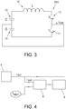
- FIG. 3 shows the equivalent circuit of a switching device 52A .
- the switching device limits the performance of the power stage.
- the equivalent circuit shown in Figure 3 comprises two capacitors 13, two switches 11 , and an inductor 12 .
- the hardware protection system uses a reference current ( I REF ) less than or equal to the maximum current (I MAX ) to ensure protection.
- the reference current (I REF ) is fixed, i.e., it has a constant value.
- the constant I REF according to the state of the art would have the value of 200 Amperes.
- FIG. 4 shows an over-current protection system of the state of the art.
- the protection system is made up of a comparator 4 with two inputs and one output.
- the output is connected to a control device 2 , one input is connected to the output of the power stage 5 for measuring the output current of the power stage, and the other input receives the reference current value for suitably protecting the power stage.
- the comparator compares the current value at the output of the power stage 5 and the reference current value I REF .
- the comparator sends the result of the comparison to the control device 2 .
- the control device 2 halts the power stage, and accordingly the power converter when the current value at the output of the power stage I OUT is higher than or equal to the reference current value I REF .
- Figure 5 shows the protection system 1 of the present invention which is made up of a control device 2 , a test generator 3 , and a comparator 4 .
- the control device comprises a processor 21 , a memory 22 , and a voltage meter 23 connected to the DC bus 51 of the power stage 5 .
- the comparator 4 has two inputs and one output. The output is connected to the control device 2 , one input is connected to the output of the power stage 5 for measuring the output current I OUT of the power stage, and the other input receives the reference current value I REF for suitably protecting the power stage. With this configuration, the comparator 4 compares the current value I OUT at the output of the power stage 5 and the reference current value I REF .
- the comparator sends the result of the comparison to the control device and also the values of the output current I OUT and reference current I REF .
- the control device 2 halts the power stage 5 if the current value I OUT at the output of the power stage 5 is higher than or equal to the reference current value I REF .
- the value of I REF calculated by the test generator 3 is a function of the DC voltage (voltage in the DC bus, Figure 1 ) measured in the power stage 5 and of the rated current I RMS of the switching device.
- the current limitation of the power stage 5 is determined by the maximum current the switching devices (I RMS ) can support.
- the test generator 3 has pairs of associated values V-I (V DC , I) that relate, for all the possible current values between zero and the current limit (I RMS ) of the switching devices, with the possible voltage V DC of the power stage (see Figure 6 ).
- the pairs of values V-I are calculated by applying the equation Eq. 2 described above. Once the pairs of values V-I have been calculated, the test generator 3 is capable of calculating the current value I REF for the voltage value V DC measured in the power stage, thereby preventing the risk of over-currents. This is because the current value at the output of the test generator (I REF ) is always less than or equal to the current limit (I RMS ) of the switching device.
- the current (I OUT ) at the output of the power stage 5 can be increased, which would increase the power of the power stage, maintaining the protection of the power stage.
- the power stage could never supply output current values (I OUT ) greater than 200 Amperes because the protection device according to the state of the art would not allow it.
- the protection device of the present invention it would be possible, for example, to increase the output current (I OUT ) to 950 Amperes for voltage values (V DC ) between 1000 Volts and 1250 Volts.
- the control device 2 performs several functions. One function is to protect the power converter, like it does conventionally. Another function is to measure the voltage in the DC bus to provide the voltage value to the test generator.
- the control device 2 may also optionally comprise a user interface (not shown) whereby a user can enter the maximum current value (I RMS ) of the switching devices and the values of the pairs of values V-I, wherein all the values (I RMS , V-I) are then sent to the test generator.
- the test generator may comprise a user interface whereby a user can enter the maximum current value (I RMS ) of the switching devices and the values of the pairs of values V-I.
- control device 2 by means of the control setpoints sent to the power stage, is capable of gradually increasing the voltage of the power stage, and therefore, the power of the power stage (power of the power converter), also adjusting the value of the protective current, I REF .
- control device 2 increased the potential V DC and reduces the protective current I REF is shown in Figure 6 .
- the control device 2 is capable of increasing the power by increasing the values of V DC to 1250 V DC while maintaining the current value I REF , and decreasing the value of I REF to 1500 V DC , this being the voltage limit for the power stage 5 , and so that the reference current I REF is equal to the current I RMS .
- the protective current I REF (200) is calculated as if the power stage always has a voltage of 1500 V, point at which the reference current I REF coincides with the current I RMS .
- the reference current I REF is calculated from the maximum current that the switching devices (therefore also the power stage 5) can support for each voltage value in which the power stage 5 operates.
Abstract
Description
- The present invention relates to a system and a method for dynamic over-current protection for power converters.
- The technical field of the invention is comprised in the field of power converters, motor controllers, and solar and wind power generation systems.
- All power converters have, as common elements, at least one DC voltage bus and one power converter bridge, formed by switching devices, the triggering of which is controlled so that the output voltage/intensity has the characteristics required by the application. Therefore, if the power converter is a solar inverter, the equipment will work as an AC current source having the same frequency as the network (typically 50/60 Hz). If the power converter is a variable speed drive, the power supply frequency will be modified so as to vary the rotational speed of three-phase asynchronous electric motors.
- The power stage is formed by one or more power modules. Each power module is formed by at least one DC voltage bus and a series of switching devices. The simplest case (DC/DC converters) would be made up of a single switching device, whereas in variable speed drives or DC/AC converters, bridges formed by several switching devices (six if the power converter bridge has two levels) will be implemented. For power converters with an AC output, the power stage incorporates a filter required for adapting the output waveform to that of the motor. If the input of the equipment is an AC source, the power stage would further include a bridge rectifier which rectifies the polarity of the input AC voltage, such that it is stable. The rectifier can be formed by diodes or transistors. This second option incorporates capacity for moving electrical energy bidirectionally, allowing the discharge in the source of excess energy.
- To ensure the correct operation of the power stage of the power converter, as well as to prevent damage from over-voltages or over-currents, the power converter incorporates protection devices connected to the power stage.
- The protection required for the power converter is mainly determined by the characteristics of the switching devices.
- Currently, the protection incorporated in power converters is hardware-type protection. The protection system consists of setting a protective current threshold, such that once said threshold is exceeded, the control of the power converter orders a halt, in this manner preventing damage in the switching devices.
- This threshold is calculated by taking into account that, when the switching device is halted, a voltage peak is produced due to the associated leakage inductances. This voltage peak is determined by the energy stored in these leakage inductances and by the capacitance of the switching device itself and of its parasitic elements. The failure detection threshold is determined based on the maximum voltage that the terminals of the switching device can support at the opening thereof when the protective current circulates through it.
- The hardware protection system uses a reference current less than or equal to the maximum current to ensure protection. In the current state of the art, the reference current is fixed, i.e., it has a constant value and the value thereof is established depending on the voltage of the DC bus.
- The main drawback of this mode of operation is that the maximum power is fixed and determined by the value of the defined reference current indicated above for carrying out the comparison. Therefore, if increasing the range of use in voltage of a power converter is desired, i.e., if gradually approaching the electrical limit (maximum voltage) thereof is desired, it is not possible to set the protections at the same level as the one mentioned above, given that, in the event of a short-circuit, the protection would halt the power stage. Furthermore, the voltage peak produced during the halt would destroy the switching devices. For this reason, the set protection value is delimited by the maximum voltage (VDC = voltage of the DC bus) of the power stage. As mentioned, this value can vary over time, but it is considered a maximum and fixed value for calculating the protection.
- Static protection circuits of the state of the art are, for example, the circuit disclosed in European patent application with publication number
EP2800260A1 which discloses a semiconductor protection circuit connected in parallel to a converter. - It would therefore be desirable to have an over-current protection system which, in addition to protecting the power converter, allows the power of the converter (the performance thereof) to be increased to the maximum operating limit, i.e., to the maximum VDC value of the power converter.
- A first aspect of the invention discloses a dynamic over-current protection system for power converters. The dynamic over-current protection system for power converters can be connected to the output of the power stage comprised in the power converter. The over-current protection system for power converters of the present invention comprises:
- a comparator that can be connected to the output of the power stage, measuring an output current (IOUT) of the power stage;
- a control device that is connected with the comparator and can be connected with the power stage, wherein the control device measures a voltage (VDC) of the power stage;
- a test generator connected with the control device and with the comparator, wherein the test generator comprises pairs of voltage-current values (VDC-IREF) that relate voltage values (VDC) of the power stage with current values between zero and a pre-established current limit (IRMS);
- The power stage comprises a DC bus and a power converter circuit. The power converter circuit comprises at least one switching device (for example, insulated-gate bipolar transistors (IGBTs)).
- The switching device has an equivalent circuit formed by at least one capacitor, a coil, and a switch.
- The pairs of voltage-current values (VDC-IREF) are calculated by applying Eq. 2 on the equivalent circuit.
- The test generator comprises the pairs of voltage-current values (VDC-IREF), wherein the pairs of voltage-current values (VDC-IREF) are calculated by means of:

- VDC. is the DC voltage of the power stage, which may vary over time;
- Vmax: the maximum voltage the terminals of the switching device can support at the opening thereof when the protective current circulates through it.
- L: leakage inductance of the switching device;
- C: capacity of the parasitic elements of the switching device.
- In one embodiment, the control device comprises at least one voltage meter for measuring the DC voltage (VDC) of the power stage.
- In another embodiment, the control device additionally comprises a processor and a memory for storing and processing control setpoints which modify the voltage value (VDC) of the power stage. The control device receives from the comparator the value of the output current (IOUT) of the power stage, the voltage of the power stage (VDC), and the value of the reference current (IREF) it stores in the memory. The control device can calculate, based on the three preceding values (VDC, IOUT, IREF), new values of the DC voltage (VDC) which it sends (by means of setpoints) to the power stage such that the power stage increases the power thereof (by means of increasing the voltage VDC) to the maximum available power of the power stage depending on the source to which the power stage is connected. The gradual increase in the value of the voltage (VDC) involves an increase in the output current of the power stage (IOUT) which the protection device allows until the value of the output current is less than or equal to the reference current value (IREF) dynamically calculated by the test generator.
- In one embodiment, the pre-established current limit (IRMS) corresponds with the current limit of the switching devices comprised in the power stage. The transistors comprised in the power stage are usually the elements limiting the current thereof. Therefore, the transistors (switching devices) will determine the maximum current value (IRMS).
- A second aspect of the invention discloses a power converter comprising the dynamic protection system according to the first aspect of the invention and for any of the embodiments thereof.
- A third aspect of the invention discloses a dynamic over-current protection method for power converters. The dynamic over-current protection method for power converters comprises the following steps of:
- generating pairs of voltage-current values (VDC-IREF) that relate voltage values (VDC) of the power stage with current values between zero and a current limit (IRMS) of switching devices comprised in the power stage;
- measuring the DC voltage (VDC) and the output current (IOUT) of the power stage;
- comparing the value of the output current (IOUT) with the current value (IREF) corresponding to the measured voltage (VDC) in the pairs of voltage-current values (VDC-IREF);
- halting the power converter if the value of the output current (IOUT) is higher than or equal to the current value (IREF) corresponding to the measured voltage (VDC) in the pairs of voltage-current values (VDC-IREF).
- In one embodiment, the dynamic over-current protection method for power converters additionally comprises increasing the DC voltage (VDC) of the power stage until meeting the condition of the value of the output current (IOUT) being smaller by a pre-established value than the current value (IREF) corresponding to the measured voltage (VDC) in the pairs of voltage-current values (VDC-IREF). A user is free to choose a pre-established value that is as small as they wish, such that the output current (IOUT) approaches that of the reference current (IREF) without actually having the same value.
-
-
Figure 1 shows a circuit of the power stage of a power converter with an over-voltage protection system connected to the output thereof. -
Figure 2 shows the voltage peak produced in the terminals of a switching device (IGBT transistor) when the switching device is halted. -
Figure 3 shows the equivalent circuit of a switching device. -
Figure 4 shows an over-voltage protection system of the state of the art. -
Figure 5 shows an over-voltage protection system according to the present invention. -
Figure 6 shows the reference current (level of protection) calculated according to the present invention with respect to the voltage (VDC) of the power stage. - An embodiment of the invention is described below in an illustrative and non-limiting manner.
-
Figure 1 shows apower stage 5 of the state of the art comprised in a power converter. Thepower stage 5 comprises theDC bus 51 and thepower converter circuit 52. Thepower converter circuit 52 is mainly formed by switchingdevices 52A. An energy source (not shown) is connected to the input of the power stage. Aprotection device 1 is connected to the output of the power stage. -
Figure 2 shows the voltage peak VMAX produced in the terminals of a switching device (for example, switchingdevice 52A) when the switching device is halted. The voltage peak is necessarily taken into account for setting a current threshold whereby the protection system protects the power converter in the event of over-voltage or over-current situations. -
Figure 3 shows the equivalent circuit of aswitching device 52A. The switching device limits the performance of the power stage. The equivalent circuit shown inFigure 3 comprises twocapacitors 13, twoswitches 11, and aninductor 12. To be able to calculate the protective current threshold, the voltage peak of the switching device at the moment said device comes to a halt must be known. The voltage peak Vmax (Figure 2 ) is determined by the energy stored in the leakage inductances (L) and by the capacitance of the switching device itself and of its parasitic elements (C), such that the following energy balance is verified:

- The hardware protection system uses a reference current (I REF) less than or equal to the maximum current (IMAX) to ensure protection. In the current state of the art, the reference current (IREF) is fixed, i.e., it has a constant value. In
Figure 6 , the constant I REF according to the state of the art would have the value of 200 Amperes. - Taking into account the foregoing,
Figure 4 shows an over-current protection system of the state of the art. The protection system is made up of acomparator 4 with two inputs and one output. The output is connected to acontrol device 2, one input is connected to the output of thepower stage 5 for measuring the output current of the power stage, and the other input receives the reference current value for suitably protecting the power stage. With this configuration, the comparator compares the current value at the output of thepower stage 5 and the reference current value IREF. The comparator sends the result of the comparison to thecontrol device 2. Thecontrol device 2 halts the power stage, and accordingly the power converter when the current value at the output of the power stage IOUT is higher than or equal to the reference current value IREF. -
Figure 5 shows theprotection system 1 of the present invention which is made up of acontrol device 2, atest generator 3, and acomparator 4. The control device comprises aprocessor 21, amemory 22, and avoltage meter 23 connected to theDC bus 51 of thepower stage 5. Thecomparator 4 has two inputs and one output. The output is connected to thecontrol device 2, one input is connected to the output of thepower stage 5 for measuring the output current IOUT of the power stage, and the other input receives the reference current value IREF for suitably protecting the power stage. With this configuration, thecomparator 4 compares the current value IOUT at the output of thepower stage 5 and the reference current value IREF. The comparator sends the result of the comparison to the control device and also the values of the output current IOUT and reference current IREF. Thecontrol device 2 halts thepower stage 5 if the current value IOUT at the output of thepower stage 5 is higher than or equal to the reference current value IREF. Unlike the state of the art, the value of IREF calculated by thetest generator 3 is a function of the DC voltage (voltage in the DC bus,Figure 1 ) measured in thepower stage 5 and of the rated current IRMS of the switching device. The current limitation of thepower stage 5 is determined by the maximum current the switching devices (IRMS) can support. Thetest generator 3 has pairs of associated values V-I (VDC, I) that relate, for all the possible current values between zero and the current limit (IRMS) of the switching devices, with the possible voltage VDC of the power stage (seeFigure 6 ). The pairs of values V-I are calculated by applying the equation Eq. 2 described above. Once the pairs of values V-I have been calculated, thetest generator 3 is capable of calculating the current value IREF for the voltage value VDC measured in the power stage, thereby preventing the risk of over-currents. This is because the current value at the output of the test generator (IREF) is always less than or equal to the current limit (IRMS) of the switching device. As shown inFigure 6 , by means of the present invention, the current (IOUT) at the output of thepower stage 5 can be increased, which would increase the power of the power stage, maintaining the protection of the power stage. Taking the values ofFigure 6 as reference, according to the state of the art, the power stage could never supply output current values (IOUT) greater than 200 Amperes because the protection device according to the state of the art would not allow it. In contrast, with the protection device of the present invention, it would be possible, for example, to increase the output current (IOUT) to 950 Amperes for voltage values (VDC) between 1000 Volts and 1250 Volts. - The
control device 2 performs several functions. One function is to protect the power converter, like it does conventionally. Another function is to measure the voltage in the DC bus to provide the voltage value to the test generator. Thecontrol device 2 may also optionally comprise a user interface (not shown) whereby a user can enter the maximum current value (IRMS) of the switching devices and the values of the pairs of values V-I, wherein all the values (IRMS, V-I) are then sent to the test generator. Optionally, the test generator may comprise a user interface whereby a user can enter the maximum current value (IRMS) of the switching devices and the values of the pairs of values V-I. - Additionally and independently, the
control device 2, by means of the control setpoints sent to the power stage, is capable of gradually increasing the voltage of the power stage, and therefore, the power of the power stage (power of the power converter), also adjusting the value of the protective current, IREF. It should be remembered that the power SOUT at the output of the power stage is defined as:
- An example of how the
control device 2 increased the potential VDC and reduces the protective current IREF is shown inFigure 6 . Thecontrol device 2 is capable of increasing the power by increasing the values of VDC to 1250 VDC while maintaining the current value IREF, and decreasing the value of IREF to 1500 VDC, this being the voltage limit for thepower stage 5, and so that the reference current IREF is equal to the current IRMS. In other words, in the state of the art the protective current IREF (200) is calculated as if the power stage always has a voltage of 1500 V, point at which the reference current IREF coincides with the current IRMS. In contrast, by means of the present invention, the reference current IREF is calculated from the maximum current that the switching devices (therefore also the power stage 5) can support for each voltage value in which thepower stage 5 operates. The relation (VDC, IREF) shown inFigure 6 can be not only discrete points, but also a continuous graph, table containing pairs of values, and any other type of relationship wherein IREF (t) = f(VDC(t)) is true.
Claims (10)
- A dynamic over-current protection system (1) for power converters, wherein the protection system is connectable to the output of a power stage (5) comprised in the power converter; the protection system is characterised in that it comprises:• a comparator (4), which is connectable to the output of the power stage (5), that measures an output current "IOUT" of the power stage;• a control device (2) that is connected with the comparator (4) and that is connectable to the power stage (5), wherein the control device (2) measures a voltage "VDC" of the power stage;• a test generator (3) connected with the control device (2) and with the comparator (4), wherein the test generator (3) comprises pairs of voltage-current values "VDC-IREF" that relate voltage values "VDC" of the power stage with current values between zero and a pre-established current limit "IRMS";such that the test generator (3) receives from the control device (2) the measured voltage value "VDC" and sends the corresponding current value "IREF" of the pairs of voltage-current values to the comparator (4), which halts the power stage if the output current "IOUT" of the power stage is higher than or equal to the current value "IREF" associated with the measured voltage "VDC".
- The protection system according to claim 1, wherein the power stage comprises a DC bus (51) and a power converter circuit (52), and wherein the power converter circuit (52) comprises at least one switching device (52A).
- The protection system according to claim 2, wherein the switching device (52A) has an equivalent circuit formed by at least one capacitor (13), a coil (12), and a switch (11).
- The protection system according to claim 2 or 3, wherein the pairs of voltage-current values "VDC-IREF" are calculated by means of:
 VDC: is the DC voltage of the power stage, which may vary over time;Vmax: the maximum voltage the terminals of the switching device can support at the opening thereof when the protective current circulates through it;L: leakage inductance of the switching device;C: capacity of the parasitic elements of the switching device.
 - The protection system according to claim 1, wherein the control device (2) comprises at least one voltage meter (23) for measuring the DC voltage "VDC" of the power stage (5).
- The protection system according to claim 1 or 5, wherein the control device (2) additionally comprises a processor (21) and a memory (22) for storing and processing control setpoints which modify the voltage value "VDC" of the power stage (5).
- The protection system according to claim 2, wherein the pre-established current limit "IRMS" corresponds with the current limit of the switching devices (52A) comprised in the power stage (5).
- A power converter, characterised in that it comprises the dynamic protection system according to any one of claims 1 to 7.
- A dynamic over-current protection method for power converters, characterised in that it comprises:• generating pairs of voltage-current values "VDC-IREF" that relate voltage values "VDC" of the power stage with current values between zero and a current limit "IRMS" of switching devices comprised in the power stage;• measuring the DC voltage "VDC" and the output current "IOUT" of the power stage;• comparing the value of the output current "IOUT" with the current value "IREF" corresponding to the measured voltage "VDC" in the pairs of voltage-current values "VDC-IREF";• halting the power converter if the value of the output current "IOUT" is higher than or equal to the current value "IREF" corresponding to the measured voltage "VDC" in the pairs of voltage-current values "VDC-IREF".
- The dynamic over-current protection method for power converters according to claim 9, wherein the method additionally comprises increasing the DC voltage "VDC" of the power stage until meeting the condition of the value of the output current "IOUT" being smaller by a pre-established value than the current value "IREF" corresponding to the measured voltage "VDC" in the pairs of voltage-current values "VDC-IREF".
Applications Claiming Priority (2)
| Application Number | Priority Date | Filing Date | Title |
|---|---|---|---|
| ES201731435A ES2717341B2 (en) | 2017-12-20 | 2017-12-20 | DYNAMIC SYSTEM AND METHOD OF PROTECTION AGAINST OVERCURRENT FOR POWER CONVERTERS |
| PCT/ES2018/070778 WO2019122469A1 (en) | 2017-12-20 | 2018-12-04 | System and method for dynamic over-current protection for power converters |
Publications (2)
| Publication Number | Publication Date |
|---|---|
| EP3731391A1 true EP3731391A1 (en) | 2020-10-28 |
| EP3731391A4 EP3731391A4 (en) | 2021-02-24 |
Family
ID=66822272
Family Applications (1)
| Application Number | Title | Priority Date | Filing Date |
|---|---|---|---|
| EP18891528.4A Withdrawn EP3731391A4 (en) | 2017-12-20 | 2018-12-04 | System and method for dynamic over-current protection for power converters |
Country Status (4)
| Country | Link |
|---|---|
| US (1) | US11283346B2 (en) |
| EP (1) | EP3731391A4 (en) |
| ES (1) | ES2717341B2 (en) |
| WO (1) | WO2019122469A1 (en) |
Families Citing this family (1)
| Publication number | Priority date | Publication date | Assignee | Title |
|---|---|---|---|---|
| ES2730451B2 (en) * | 2018-05-09 | 2020-10-06 | Power Electronics Espana S L | MODULAR PHOTOVOLTAIC SOLAR INVERTER |
Family Cites Families (9)
| Publication number | Priority date | Publication date | Assignee | Title |
|---|---|---|---|---|
| US4415960A (en) * | 1982-03-29 | 1983-11-15 | Sperry Corporation | Line variable overcurrent protection for a voltage conversion circuit |
| US8488342B2 (en) * | 2008-10-21 | 2013-07-16 | On-Bright Electronics (Shanghai) Co., Ltd. | Systems and methods for constant voltage mode and constant current mode in flyback power converters with primary-side sensing and regulation |
| DE102009055055A1 (en) | 2009-12-21 | 2011-06-22 | Robert Bosch GmbH, 70469 | Method for fault detection in an electrical machine controlled by an inverter in a motor vehicle and device for monitoring an operation of the electric machine |
| JP5699470B2 (en) * | 2010-07-21 | 2015-04-08 | ソニー株式会社 | Switching power supply |
| CN102624237B (en) * | 2011-02-01 | 2015-09-16 | 昂宝电子(上海)有限公司 | For the system and method that the dynamic threshold of flyback power supply converter regulates |
| KR101255959B1 (en) | 2011-12-28 | 2013-04-23 | 주식회사 효성 | Protection circuit for protecting voltage source converter |
| CN103795034A (en) * | 2012-10-30 | 2014-05-14 | 通用电气公司 | Overcurrent protection system and method |
| US9054525B2 (en) * | 2013-03-13 | 2015-06-09 | Google Technology Holdings LLC | Methods and apparatus for dynamically adjusting an over-current protection threshold |
| US9461559B2 (en) | 2013-03-15 | 2016-10-04 | Rockwell Automation Technologies, Inc. | Active front end power converter with boost mode derating to protect filter inductor |
-
2017
- 2017-12-20 ES ES201731435A patent/ES2717341B2/en active Active
-
2018
- 2018-12-04 US US16/956,119 patent/US11283346B2/en active Active
- 2018-12-04 WO PCT/ES2018/070778 patent/WO2019122469A1/en unknown
- 2018-12-04 EP EP18891528.4A patent/EP3731391A4/en not_active Withdrawn
Also Published As
| Publication number | Publication date |
|---|---|
| US11283346B2 (en) | 2022-03-22 |
| US20200328670A1 (en) | 2020-10-15 |
| ES2717341B2 (en) | 2020-07-06 |
| WO2019122469A1 (en) | 2019-06-27 |
| ES2717341A1 (en) | 2019-06-20 |
| EP3731391A4 (en) | 2021-02-24 |
Similar Documents
| Publication | Publication Date | Title |
|---|---|---|
| US10090776B2 (en) | Method to protect a power converter arrangement and power converter arrangement with a protective device | |
| US8902616B2 (en) | Active front end power converter with diagnostic and failure prevention using peak detector with decay | |
| EP2784926B1 (en) | Voltage balancing system and method for multilevel converters | |
| US7804271B2 (en) | Multiphase current supplying circuit, driving apparatus, compressor and air conditioner | |
| EP3324531A1 (en) | Power conversion device | |
| US9602019B2 (en) | Voltage-adjusting device and method in power conversion system | |
| EP3285380B1 (en) | Voltage balancing of voltage source converters | |
| EP3514941A1 (en) | Power conversion apparatus and power system | |
| EP2053728A2 (en) | Adjustable speed drive protection | |
| JPS6056388B2 (en) | Controlled current inverter device | |
| JP6334336B2 (en) | Power converter | |
| US8670253B2 (en) | Converter protecting components against overvoltages | |
| US20180269805A1 (en) | Control of parallel connected power devices | |
| US11283346B2 (en) | System and method for dynamic over-current protection for power converters | |
| JPWO2013054567A1 (en) | Power converter | |
| Guo et al. | A self-voltage balanced hybrid three-level MV inverter using 3.3-kV SiC MOSFET module with false-trigger-proof design | |
| CN112152183B (en) | Method for operating a converter and converter arrangement | |
| JPH07250484A (en) | High-voltage self-excited converter for interconnected system | |
| US10122253B2 (en) | Power conversion apparatus and initial charging method of the same | |
| KR20180117928A (en) | Power converting apparatus | |
| JP3722649B2 (en) | 3-level inverter | |
| EP3829047A1 (en) | Converter | |
| Alwash et al. | Analysis of voltage source converters under DC line-to-line short-circuit fault conditions | |
| Zheng et al. | A Flexible and Secure Evaluation Platform for Overvoltage Protection in Power Electronics Systems | |
| WO1996013091A1 (en) | Transient suppressor for electronics systems |
Legal Events
| Date | Code | Title | Description |
|---|---|---|---|
| STAA | Information on the status of an ep patent application or granted ep patent |
Free format text: STATUS: THE INTERNATIONAL PUBLICATION HAS BEEN MADE |
|
| PUAI | Public reference made under article 153(3) epc to a published international application that has entered the european phase |
Free format text: ORIGINAL CODE: 0009012 |
|
| STAA | Information on the status of an ep patent application or granted ep patent |
Free format text: STATUS: REQUEST FOR EXAMINATION WAS MADE |
|
| 17P | Request for examination filed |
Effective date: 20200619 |
|
| AK | Designated contracting states |
Kind code of ref document: A1 Designated state(s): AL AT BE BG CH CY CZ DE DK EE ES FI FR GB GR HR HU IE IS IT LI LT LU LV MC MK MT NL NO PL PT RO RS SE SI SK SM TR |
|
| AX | Request for extension of the european patent |
Extension state: BA ME |
|
| A4 | Supplementary search report drawn up and despatched |
Effective date: 20210121 |
|
| RIC1 | Information provided on ipc code assigned before grant |
Ipc: H02M 1/32 20070101AFI20210115BHEP |
|
| RAP1 | Party data changed (applicant data changed or rights of an application transferred) |
Owner name: POWER ELECTRONICS ESPANA, S.L. |
|
| RIN1 | Information on inventor provided before grant (corrected) |
Inventor name: SALVO LILLO, DAVID Inventor name: SALVO LILLO, ABELARDO Inventor name: POVEDA LERMA, ANTONIO |
|
| DAV | Request for validation of the european patent (deleted) | ||
| DAX | Request for extension of the european patent (deleted) | ||
| STAA | Information on the status of an ep patent application or granted ep patent |
Free format text: STATUS: THE APPLICATION IS DEEMED TO BE WITHDRAWN |
|
| 18D | Application deemed to be withdrawn |
Effective date: 20210820 |