EP3731362A1 - Connecting apparatus - Google Patents
Connecting apparatus Download PDFInfo
- Publication number
- EP3731362A1 EP3731362A1 EP18893235.4A EP18893235A EP3731362A1 EP 3731362 A1 EP3731362 A1 EP 3731362A1 EP 18893235 A EP18893235 A EP 18893235A EP 3731362 A1 EP3731362 A1 EP 3731362A1
- Authority
- EP
- European Patent Office
- Prior art keywords
- light emission
- connection
- power supply
- supply module
- connection apparatus
- Prior art date
- Legal status (The legal status is an assumption and is not a legal conclusion. Google has not performed a legal analysis and makes no representation as to the accuracy of the status listed.)
- Pending
Links
Images


Classifications
-
- H—ELECTRICITY
- H02—GENERATION; CONVERSION OR DISTRIBUTION OF ELECTRIC POWER
- H02J—ELECTRIC POWER NETWORKS; CIRCUIT ARRANGEMENTS OR SYSTEMS FOR SUPPLYING OR DISTRIBUTING ELECTRIC POWER; SYSTEMS FOR STORING ELECTRIC ENERGY
- H02J9/00—Circuit arrangements for emergency or stand-by power supply, e.g. for emergency lighting
- H02J9/005—Circuit arrangements for emergency or stand-by power supply, e.g. for emergency lighting using a power saving mode
- H02J9/007—Detection of the absence of a load
-
- H—ELECTRICITY
- H02—GENERATION; CONVERSION OR DISTRIBUTION OF ELECTRIC POWER
- H02J—ELECTRIC POWER NETWORKS; CIRCUIT ARRANGEMENTS OR SYSTEMS FOR SUPPLYING OR DISTRIBUTING ELECTRIC POWER; SYSTEMS FOR STORING ELECTRIC ENERGY
- H02J1/00—Circuit arrangements for DC mains or DC distribution networks
- H02J1/001—Hot plugging or unplugging of load or power modules to or from power distribution networks
-
- H—ELECTRICITY
- H02—GENERATION; CONVERSION OR DISTRIBUTION OF ELECTRIC POWER
- H02J—ELECTRIC POWER NETWORKS; CIRCUIT ARRANGEMENTS OR SYSTEMS FOR SUPPLYING OR DISTRIBUTING ELECTRIC POWER; SYSTEMS FOR STORING ELECTRIC ENERGY
- H02J2105/00—Networks for supplying or distributing electric power characterised by their spatial reach or by the load
- H02J2105/50—Networks for supplying or distributing electric power characterised by their spatial reach or by the load for selectively controlling the operation of the loads
- H02J2105/57—Networks for supplying or distributing electric power characterised by their spatial reach or by the load for selectively controlling the operation of the loads according to a pre-established time schedule
-
- H—ELECTRICITY
- H02—GENERATION; CONVERSION OR DISTRIBUTION OF ELECTRIC POWER
- H02J—ELECTRIC POWER NETWORKS; CIRCUIT ARRANGEMENTS OR SYSTEMS FOR SUPPLYING OR DISTRIBUTING ELECTRIC POWER; SYSTEMS FOR STORING ELECTRIC ENERGY
- H02J7/00—Circuit arrangements for charging or discharging batteries or for supplying loads from batteries
- H02J7/34—Parallel operation in networks using both storage and other DC sources, e.g. providing buffering
- H02J7/35—Parallel operation in networks using both storage and other DC sources, e.g. providing buffering with light sensitive cells
-
- H—ELECTRICITY
- H02—GENERATION; CONVERSION OR DISTRIBUTION OF ELECTRIC POWER
- H02J—ELECTRIC POWER NETWORKS; CIRCUIT ARRANGEMENTS OR SYSTEMS FOR SUPPLYING OR DISTRIBUTING ELECTRIC POWER; SYSTEMS FOR STORING ELECTRIC ENERGY
- H02J7/00—Circuit arrangements for charging or discharging batteries or for supplying loads from batteries
- H02J7/80—Circuit arrangements for charging or discharging batteries or for supplying loads from batteries including monitoring or indicating arrangements
-
- H—ELECTRICITY
- H02—GENERATION; CONVERSION OR DISTRIBUTION OF ELECTRIC POWER
- H02S—GENERATION OF ELECTRIC POWER BY CONVERSION OF INFRARED RADIATION, VISIBLE LIGHT OR ULTRAVIOLET LIGHT, e.g. USING PHOTOVOLTAIC [PV] MODULES
- H02S40/00—Components or accessories in combination with PV modules, not provided for in groups H02S10/00 - H02S30/00
- H02S40/30—Electrical components
- H02S40/34—Electrical components comprising specially adapted electrical connection means to be structurally associated with the PV module, e.g. junction boxes
-
- H—ELECTRICITY
- H05—ELECTRIC TECHNIQUES NOT OTHERWISE PROVIDED FOR
- H05B—ELECTRIC HEATING; ELECTRIC LIGHT SOURCES NOT OTHERWISE PROVIDED FOR; CIRCUIT ARRANGEMENTS FOR ELECTRIC LIGHT SOURCES, IN GENERAL
- H05B45/00—Circuit arrangements for operating light-emitting diodes [LED]
- H05B45/10—Controlling the intensity of the light
-
- Y—GENERAL TAGGING OF NEW TECHNOLOGICAL DEVELOPMENTS; GENERAL TAGGING OF CROSS-SECTIONAL TECHNOLOGIES SPANNING OVER SEVERAL SECTIONS OF THE IPC; TECHNICAL SUBJECTS COVERED BY FORMER USPC CROSS-REFERENCE ART COLLECTIONS [XRACs] AND DIGESTS
- Y02—TECHNOLOGIES OR APPLICATIONS FOR MITIGATION OR ADAPTATION AGAINST CLIMATE CHANGE
- Y02B—CLIMATE CHANGE MITIGATION TECHNOLOGIES RELATED TO BUILDINGS, e.g. HOUSING, HOUSE APPLIANCES OR RELATED END-USER APPLICATIONS
- Y02B20/00—Energy efficient lighting technologies, e.g. halogen lamps or gas discharge lamps
- Y02B20/40—Control techniques providing energy savings, e.g. smart controller or presence detection
-
- Y—GENERAL TAGGING OF NEW TECHNOLOGICAL DEVELOPMENTS; GENERAL TAGGING OF CROSS-SECTIONAL TECHNOLOGIES SPANNING OVER SEVERAL SECTIONS OF THE IPC; TECHNICAL SUBJECTS COVERED BY FORMER USPC CROSS-REFERENCE ART COLLECTIONS [XRACs] AND DIGESTS
- Y02—TECHNOLOGIES OR APPLICATIONS FOR MITIGATION OR ADAPTATION AGAINST CLIMATE CHANGE
- Y02E—REDUCTION OF GREENHOUSE GAS [GHG] EMISSIONS, RELATED TO ENERGY GENERATION, TRANSMISSION OR DISTRIBUTION
- Y02E10/00—Energy generation through renewable energy sources
- Y02E10/50—Photovoltaic [PV] energy
Definitions
- the present disclosure relates to a connection apparatus.
- portable energy harvesting apparatuses that generate electric power in accordance with the external environment so that users can supply power to loads such as portable electronic devices, including smartphones, notebook personal computers (PCs) and tablet PCs, even in outdoor areas where they cannot obtain commercial power supply.
- portable electronic devices including smartphones, notebook personal computers (PCs) and tablet PCs
- Examples of such an energy harvesting apparatus include a solar cell module including solar cells that generate power using light energy such as solar light.
- connection apparatus it is desirable that the user can recognize that the power supply module has been securely connected to the connection apparatus.
- One known way of allowing users to recognize the connection of the connector is to use a buzzer that produces sound when the connector has been connected (see PTL 1).
- Power supply modules such as solar cell modules are limited in terms of the amount of available power. Hence, it has been required to allow, at low power consumption, users to recognize that the power supply module has been connected to the connection apparatus.
- an object of the present disclosure is to solve the above-described problem, and to provide a connection apparatus capable of allowing, at low power consumption, users to recognize the connection of a power supply module.
- connection apparatus capable of supplying power supplied from a power supply module to a load
- the connection apparatus comprising: a connection unit connectable with the power supply module; a light emission element; and a light emission controller for controlling the light emission element, wherein the light emission controller causes, upon detection of a connection of the power supply module to the connection unit, the light emission element to emit light for a first predetermined time.
- connection apparatus further comprises an output controller for controlling supply of power from the connection apparatus to the load, wherein the output controller cuts off, upon detection of a connection of the power supply module to the connection unit, the supply of the power to the load for a second predetermined time that is longer than the first predetermined time.
- the output controller includes a resistor, a capacitor and a transistor.
- the output controller includes a timer. With such a configuration, it is possible to accurately determine the second predetermined time.
- the light emission controller includes a resistor, a capacitor, and a transistor. With such a configuration, it is possible to allow the light emission element to emit light for the first predetermined time with a simple configuration.
- the light emission controller includes a timer. With such a configuration, it is possible to accurately determine the first predetermined time.
- connection unit is a connector including an electrode which receives power from the power supply module.
- the light emission element is a light emission diode. With such a configuration, it is possible to further reduce power consumption when allowing users to recognize the connection of the power supply module.
- connection apparatus capable of allowing, at low power consumption, users to recognize the connection of a power supply module.
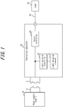
- FIG. 1 is a block diagram showing a schematic configuration of a connection apparatus 20 according to an embodiment of the present disclosure.
- the connection apparatus 20 is connectable to a power supply module 10 and can receive power from the power supply module 10 when connected to the power supply module 10.
- FIG. 1 shows a state in which the power supply module 10 is not connected to the connection apparatus 20.
- the connection apparatus 20 is connectable to a load 30 via a cable 40.
- the connection apparatus 20 can supply power, supplied from the power supply module 10, to the load 30 via the cable 40.
- connection apparatus 20 includes a connection unit 21 connectable to the power supply module 10.
- the connection apparatus 20 includes, as functional blocks, a light emission element 22, a light emission controller 23, and an output controller 24.
- connection unit 21 is mechanically connectable to a connection unit 11 of the power supply module 10.
- the connection unit 21 may have a shape corresponding to the shape of the connection unit 11 of the power supply module 10 so that the connection apparatus 20 and the power supply module 10 are mechanically connected together by the connection unit 21 and the connection unit 11 being fitted to each other.
- connection unit 21 is electrically connected to the power supply module 10 by mechanically being connected to the connection unit 11 of the power supply module 10.
- the connection apparatus 20 can receive power from the power supply module 10.
- the connection unit 21 may be, for example, a connector including an electrode which can receive power from the power supply module 10.
- the power supply module 10 may be a power generation module that generates power according to the external environment.
- the power supply module 10 may be, for example, a power generation module including a solar cell that photoelectrically converts incident light such as sunlight or room light to generate power.
- the power supply module 10 may be, for example, a power generation module that generates power using energy such as geothermal energy.
- the power supply module 10 is not limited to a power generation module and may be a battery module including a primary or secondary battery.
- the secondary battery may be, for example, a lithium-ion battery or a nickel-metal hydride battery.
- the light emission element 22 is an element that emits light when a current flows therethrough.
- the light emission element 22 may be, for example, a light emission diode (LED) or a light bulb.
- LED light emission diode
- the light emitting element 22 is a light emission diode, it is possible to cause the light emission element 22 to emit light at low power consumption.
- the light emission controller 23 controls the light emission element 22.
- the light emission controller 23 detects a connection of the power supply module 10 to the connection unit 21.
- the light emission controller 23 for example, detects whether a voltage has been applied to the electrode of the connection unit 21 to detect a connection of the power supply module 10 to the connection unit 21.
- the light emission controller 23 When the light emission controller 23 has detected that the power supply module 10 is connected to the connection unit 21, the light emission controller allows a current to flow through the light emission element 22 for a first predetermined time to cause the light emission element 22 to emit light. When the first predetermined time has elapsed after detecting the connection of the power supply module 10 to the connection unit 21, the light emission controller 23 turns off the light emission element 22.
- the first predetermined time is, for example, several seconds or so.
- the light emission controller 23 may be configured, for example, as a circuit including a capacitor and define the first predetermined time by utilizing a time constant for charging the capacitor.
- the light emission controller 23 may include, for example, a timer and define the first predetermined time by the timer.
- FIGS. 2A to 2C show how the light emission controller 23 controls the light emission element 22.
- FIGS. 2A to 2C as the components of the connection apparatus 20, components other than the light emission element 22 are not shown.
- FIG 2A is a diagram showing a state where the power supply module 10 is not connected to the connection apparatus 20. In a state where the power supply module 10 is not connected to the connection apparatus 20, no power is supplied to the connection apparatus 20, so that the light emission element 22 is turned off.
- FIG 2B is a diagram showing a state immediately after the power supply module 10 has been connected to the connection apparatus 20.
- the light emission controller 23 Upon detection of a connection of the power supply module 10 to the connection apparatus 20, the light emission controller 23 turns on the light emission element 22 to emit light.
- the user can easily recognize that the power supply module 10 has been electrically connected to the connection apparatus 20 and the supply of power from the power supply module 10 to the connection apparatus 20 has started.
- FIG 2C is a diagram showing a state after the first predetermined time has elapsed since the connection of the power supply module 10 to the connection apparatus 20.
- the light emission controller 23 turns off the light emission element 22 to stop emission of light. This prevents wasteful power consumption due to a continued flow of a current passing through the light emission element 22 even after the user has already recognized the connection of the power supply module 10 to the connection apparatus 20.
- connection apparatus 20 In a case where a plurality of connection apparatuses 20 is provided and power supply modules 10 are to be connected to the respective connection apparatuses 20 at the same time, it is difficult to allow the user to recognize individual connections by notifying the user of the detection of connection using a sound such as that from a buzzer.
- the connection apparatus 20 according to the present embodiment utilizes light emission from the light emission element 22 for user's recognition of connection between the power supply module 10 and the connection apparatus 20.
- the connection apparatus 20 does not cause noise problems because light emission from the light emission element 22 is utilized to allow the user to recognize the connection between the power supply module 10 and the connection apparatus 20.
- the output controller 24 controls supply of power from the connection apparatus 20 to the load 30.
- the load 30 include radios, lighting devices, loudspeakers, displays, electric toys, and secondary batteries.
- the output controller 24 detects a connection of the power supply module 10 to the connection unit 21.
- the output controller 24 cuts off, upon detecting that the power supply module 10 has been connected to the connection unit 21, the supply of power from the connection apparatus 20 to the load 30 for a second predetermined time.
- the output controller 24 may, for example, be configured to have a switch which can disconnect a connection between the electrode within the connection unit 21 and the output terminal of the connection apparatus 20.
- the output controller 24 can control the output of the connection apparatus 20 by turning off the switch so that no power is supplied from the power supply module 10 to the load 30 for the second predetermined time.
- the second predetermined time is longer than the first predetermined time.
- the output controller 24 controls the supply of power from the connection apparatus 20 to the load 30 so as to supply power from the connection apparatus 20 to the load 30 when the second predetermined time has elapsed after detection of the connection of the power supply module 10 to the connection unit 21.
- the output controller 24 may be configured, for example, as a circuit including a capacitor and utilize a time constant for charging the capacitor to define the second predetermined time.
- the output controller 24 may include, for example, a timer, and define the second predetermined time by the timer.
- the output controller 24 controls the supply of power such that the power supplied from the power supply module 10 is not supplied to the load 30 for the second predetermined time that is longer than the first predetermined time even when the power supply module 10 is connected to the connection apparatus 20. This ensures that the light emission element 22 is caused to emit light for the first predetermined time after the power supply module 10 has been connected to the connection apparatus 20, no matter what kind of load is connected to the connection apparatus 20 as the load 30. Further, even when the load 30 is not connected to the connection apparatus 20, it is possible to ensure that the light emission element 22 is caused to emit light for the first predetermined time after the power supply module 10 has been connected to the connection apparatus 20.
- FIG. 3 is a diagram showing an example of a circuit configuration of the connection apparatus 20 according to an embodiment of the present disclosure.
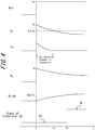
- FIG. 4 is a diagram showing voltage changes with time of node Vcc, VA and VB, changes with time of current Ic flowing through a light emission diode D1, changes with time of the state of a transistor S2, etc., in the circuit configuration shown in FIG. 3 .
- the left area A surrounded by a broken line corresponds to the light emission element 22 and the light emission controller 23 shown in FIG. 1 .
- the right area B surrounded by a broken line corresponds to the output controller 24 shown in FIG. 1 .
- the region A contains a resistor R1, a resistor R3, a resistor R4, a capacitor C1, a light emission diode D1, and a transistor S1.
- the transistor S1 is an npn transistor.
- the light emission diode D1 functions as the light emission element 22 shown in FIG. 1
- the other elements function as the light emission controller 23 shown in FIG. 1 .
- the node Vcc in FIG. 3 shows a voltage of the electrode in the connection unit 21 shown in FIG. 1 . That is, when the power supply module 10 capable of supplying voltage Vs is connected to the connection apparatus 20, Vcc equals to Vs.
- a voltage at which the transistor S1 is turned on typically about 0.6V
- Ic in the region A denotes a current that flows through the light emission diode D1.
- Ic is positive and a current flows through the light emission diode D1.
- the light emission diode D1 emits light.
- the region B contains a resistor R2, a resistor R5, a capacitor C2, and a transistor S2.
- the transistor S2 is a p-channel metal-oxide semiconductor field-effect transistor (MOSFET).
- the node VB is connected to the gate of the transistor S2 via the resistor R5.
- the voltage of Vs-VB corresponding to the absolute value of the voltage between the gate and source of the transistor S2 is shown in FIG. 4 .
- the connection apparatus 20 does not supply power supplied from the power supply module 10 to the load 30.
- the connection apparatus 20 supplies the power supplied from the power supply module 10 to the load 30.
- the time constant determined by the resistor R2 and the capacitor C2 is greater than the time constant determined by the resistor R1 and the capacitor C1.
- the capacitance of the capacitor C2 is greater than the capacitance of the capacitor C1.
- the second predetermined time is longer than the first predetermined time.
- both the light emission controller 23 and the output controller 24 are configured to detect a connection of the power supply module 10 to the connection unit 21.
- only one of them may be configured to detect the connection.
- the light emission controller 23 when only the light emission controller 23 is configured to detect a connection of the power supply module 10 to the connection unit 21, the light emission controller 23 notifies, upon detection of connection, the output controller 24 of the detection of connection.
- the output controller 24 when only the output controller 24 is configured to detect a detection of the power supply module 10 to the connection unit 21, the output controller 24 notifies, upon detection of connection, the light emission controller 23 of detection of connection.
- connection apparatus capable of allowing, at low power consumption, users to recognize the connection of a power supply module.
Landscapes
- Engineering & Computer Science (AREA)
- Power Engineering (AREA)
- Business, Economics & Management (AREA)
- Emergency Management (AREA)
- Charge And Discharge Circuits For Batteries Or The Like (AREA)
- Circuit Arrangement For Electric Light Sources In General (AREA)
- Direct Current Feeding And Distribution (AREA)
- Led Devices (AREA)
Abstract
Description
- The present disclosure relates to a connection apparatus.
- In recent years, there has been a growing demand for portable energy harvesting apparatuses that generate electric power in accordance with the external environment so that users can supply power to loads such as portable electronic devices, including smartphones, notebook personal computers (PCs) and tablet PCs, even in outdoor areas where they cannot obtain commercial power supply. Examples of such an energy harvesting apparatus include a solar cell module including solar cells that generate power using light energy such as solar light.
- When supplying power to a load using a power supply module such as a solar cell module, it is conceivable to employ such a configuration where the power supply module is connected to a connection apparatus to supply power to the load connected to the connection apparatus.
- In this case, it is desirable that the user can recognize that the power supply module has been securely connected to the connection apparatus. One known way of allowing users to recognize the connection of the connector is to use a buzzer that produces sound when the connector has been connected (see PTL 1).
- PTL 1:
JP2010266981A - Power supply modules such as solar cell modules are limited in terms of the amount of available power. Hence, it has been required to allow, at low power consumption, users to recognize that the power supply module has been connected to the connection apparatus.
- Accordingly, an object of the present disclosure is to solve the above-described problem, and to provide a connection apparatus capable of allowing, at low power consumption, users to recognize the connection of a power supply module.
- An object of the present disclosure is to advantageously solve the above problem, and the disclosed connection apparatus is a connection apparatus capable of supplying power supplied from a power supply module to a load, the connection apparatus comprising: a connection unit connectable with the power supply module; a light emission element; and a light emission controller for controlling the light emission element, wherein the light emission controller causes, upon detection of a connection of the power supply module to the connection unit, the light emission element to emit light for a first predetermined time. With such a configuration, it is possible to allow users to recognize, by means of light emission of the light emission element, that the power supply module has been connected to the connection unit. Further, by causing the light emission element to emit light only for the first predetermined time and then turning off the light emission element, it is possible to reduce power consumption. In this way, the disclosed connection apparatus can allow, at low power consumption, users to recognize the connection of the power supply module.
- It is preferred that the disclosed connection apparatus further comprises an output controller for controlling supply of power from the connection apparatus to the load, wherein the output controller cuts off, upon detection of a connection of the power supply module to the connection unit, the supply of the power to the load for a second predetermined time that is longer than the first predetermined time. With such a configuration, it is possible to ensure that the light emission element emits light regardless of the type of the load connected to the connection apparatus.
- In the disclosed connection apparatus, it is preferred that the output controller includes a resistor, a capacitor and a transistor. With such a configuration, it is possible to cut off the supply of power to the load for the second predetermined time with a simple configuration.
- In the disclosed connection apparatus, it is preferred that the output controller includes a timer. With such a configuration, it is possible to accurately determine the second predetermined time.
- In the disclosed connection apparatus, it is preferred the light emission controller includes a resistor, a capacitor, and a transistor. With such a configuration, it is possible to allow the light emission element to emit light for the first predetermined time with a simple configuration.
- In the disclosed connection apparatus, it is preferred that the light emission controller includes a timer. With such a configuration, it is possible to accurately determine the first predetermined time.
- In the disclosed connection apparatus, it is preferred that the connection unit is a connector including an electrode which receives power from the power supply module.
- In the disclosed connection apparatus, it is preferred that the light emission element is a light emission diode. With such a configuration, it is possible to further reduce power consumption when allowing users to recognize the connection of the power supply module.
- According to the present disclosure, it is possible to provide a connection apparatus capable of allowing, at low power consumption, users to recognize the connection of a power supply module.
- In the accompanying drawings:
-
FIG. 1 is a block diagram showing a schematic configuration of a connection apparatus according to an embodiment of the present disclosure; -
FIG. 2A is a diagram showing an operation of a light emission element of the connection apparatus ofFIG. 1 ; -
FIG. 2B is a diagram showing an operation of a light emission element of the connection apparatus ofFIG. 1 ; -
FIG. 2C is a diagram showing an operation of a light emission element of the connection apparatus ofFIG. 1 ; -
FIG. 3 is a diagram showing an example of a circuit configuration of a connection apparatus according to an embodiment of the present disclosure; and -
FIG. 4 is a diagram showing changes with time of voltage/current within the circuit configuration shown inFIG. 3 . - Hereinafter, an embodiment of the present disclosure will be described with reference to the accompanying drawings. The common components in the drawings are denoted by the same reference numerals.
-
FIG. 1 is a block diagram showing a schematic configuration of aconnection apparatus 20 according to an embodiment of the present disclosure. Theconnection apparatus 20 is connectable to apower supply module 10 and can receive power from thepower supply module 10 when connected to thepower supply module 10.FIG. 1 shows a state in which thepower supply module 10 is not connected to theconnection apparatus 20. Further, theconnection apparatus 20 is connectable to aload 30 via acable 40. Theconnection apparatus 20 can supply power, supplied from thepower supply module 10, to theload 30 via thecable 40. - The
connection apparatus 20 includes aconnection unit 21 connectable to thepower supply module 10. Theconnection apparatus 20 includes, as functional blocks, alight emission element 22, alight emission controller 23, and anoutput controller 24. - The
connection unit 21 is mechanically connectable to aconnection unit 11 of thepower supply module 10. For example, theconnection unit 21 may have a shape corresponding to the shape of theconnection unit 11 of thepower supply module 10 so that theconnection apparatus 20 and thepower supply module 10 are mechanically connected together by theconnection unit 21 and theconnection unit 11 being fitted to each other. - The
connection unit 21 is electrically connected to thepower supply module 10 by mechanically being connected to theconnection unit 11 of thepower supply module 10. When theconnection unit 21 and theconnection unit 11 of thepower supply module 10 are mechanically connected, theconnection apparatus 20 can receive power from thepower supply module 10. Theconnection unit 21 may be, for example, a connector including an electrode which can receive power from thepower supply module 10. - The
power supply module 10 may be a power generation module that generates power according to the external environment. Thepower supply module 10 may be, for example, a power generation module including a solar cell that photoelectrically converts incident light such as sunlight or room light to generate power. Alternatively, thepower supply module 10 may be, for example, a power generation module that generates power using energy such as geothermal energy. - The
power supply module 10 is not limited to a power generation module and may be a battery module including a primary or secondary battery. The secondary battery may be, for example, a lithium-ion battery or a nickel-metal hydride battery. - The
light emission element 22 is an element that emits light when a current flows therethrough. Thelight emission element 22 may be, for example, a light emission diode (LED) or a light bulb. In particular, when thelight emitting element 22 is a light emission diode, it is possible to cause thelight emission element 22 to emit light at low power consumption. - The
light emission controller 23 controls thelight emission element 22. Thelight emission controller 23 detects a connection of thepower supply module 10 to theconnection unit 21. Thelight emission controller 23, for example, detects whether a voltage has been applied to the electrode of theconnection unit 21 to detect a connection of thepower supply module 10 to theconnection unit 21. - When the
light emission controller 23 has detected that thepower supply module 10 is connected to theconnection unit 21, the light emission controller allows a current to flow through thelight emission element 22 for a first predetermined time to cause thelight emission element 22 to emit light. When the first predetermined time has elapsed after detecting the connection of thepower supply module 10 to theconnection unit 21, thelight emission controller 23 turns off thelight emission element 22. The first predetermined time is, for example, several seconds or so. Thelight emission controller 23 may be configured, for example, as a circuit including a capacitor and define the first predetermined time by utilizing a time constant for charging the capacitor. Thelight emission controller 23 may include, for example, a timer and define the first predetermined time by the timer. -
FIGS. 2A to 2C show how thelight emission controller 23 controls thelight emission element 22. InFIGS. 2A to 2C , as the components of theconnection apparatus 20, components other than thelight emission element 22 are not shown. -
FIG 2A is a diagram showing a state where thepower supply module 10 is not connected to theconnection apparatus 20. In a state where thepower supply module 10 is not connected to theconnection apparatus 20, no power is supplied to theconnection apparatus 20, so that thelight emission element 22 is turned off. -
FIG 2B is a diagram showing a state immediately after thepower supply module 10 has been connected to theconnection apparatus 20. Upon detection of a connection of thepower supply module 10 to theconnection apparatus 20, thelight emission controller 23 turns on thelight emission element 22 to emit light. Thus, the user can easily recognize that thepower supply module 10 has been electrically connected to theconnection apparatus 20 and the supply of power from thepower supply module 10 to theconnection apparatus 20 has started. -
FIG 2C is a diagram showing a state after the first predetermined time has elapsed since the connection of thepower supply module 10 to theconnection apparatus 20. When the first predetermined time has elapsed after detection of the connection of thepower supply module 10 to theconnection apparatus 20, thelight emission controller 23 turns off thelight emission element 22 to stop emission of light. This prevents wasteful power consumption due to a continued flow of a current passing through thelight emission element 22 even after the user has already recognized the connection of thepower supply module 10 to theconnection apparatus 20. - In a case where a plurality of
connection apparatuses 20 is provided andpower supply modules 10 are to be connected to therespective connection apparatuses 20 at the same time, it is difficult to allow the user to recognize individual connections by notifying the user of the detection of connection using a sound such as that from a buzzer. In contrast, theconnection apparatus 20 according to the present embodiment utilizes light emission from thelight emission element 22 for user's recognition of connection between thepower supply module 10 and theconnection apparatus 20. Hence, even whenpower supply modules 10 are connected one by one to the plurality ofconnection apparatuses 20 at the same time, the user can recognize the individual connections. Notification of the detection of connection using a sound such as that from a buzzer may cause noise problems. In contrast, theconnection apparatus 20 according to the present embodiment does not cause noise problems because light emission from thelight emission element 22 is utilized to allow the user to recognize the connection between thepower supply module 10 and theconnection apparatus 20. - The
output controller 24 controls supply of power from theconnection apparatus 20 to theload 30. Examples of theload 30 include radios, lighting devices, loudspeakers, displays, electric toys, and secondary batteries. - The
output controller 24 detects a connection of thepower supply module 10 to theconnection unit 21. Theoutput controller 24, for example, detects whether a voltage has been applied to the electrode of theconnection unit 21 to detect a connection of thepower supply module 10 to theconnection unit 21. - The
output controller 24 cuts off, upon detecting that thepower supply module 10 has been connected to theconnection unit 21, the supply of power from theconnection apparatus 20 to theload 30 for a second predetermined time. Theoutput controller 24 may, for example, be configured to have a switch which can disconnect a connection between the electrode within theconnection unit 21 and the output terminal of theconnection apparatus 20. Theoutput controller 24 can control the output of theconnection apparatus 20 by turning off the switch so that no power is supplied from thepower supply module 10 to theload 30 for the second predetermined time. - The second predetermined time is longer than the first predetermined time. Thus, when the
power supply module 10 is connected to theconnection unit 21, theoutput controller 24 controls the supply of power from theconnection apparatus 20 to theload 30 such that no power is supplied from theconnection apparatus 20 to theload 30 during the time when thelight emission controller 23 causes thelight emission element 22 to emit light. - The
output controller 24 controls the supply of power from theconnection apparatus 20 to theload 30 so as to supply power from theconnection apparatus 20 to theload 30 when the second predetermined time has elapsed after detection of the connection of thepower supply module 10 to theconnection unit 21. - The
output controller 24 may be configured, for example, as a circuit including a capacitor and utilize a time constant for charging the capacitor to define the second predetermined time. Theoutput controller 24 may include, for example, a timer, and define the second predetermined time by the timer. - In the manner described above, the
output controller 24 controls the supply of power such that the power supplied from thepower supply module 10 is not supplied to theload 30 for the second predetermined time that is longer than the first predetermined time even when thepower supply module 10 is connected to theconnection apparatus 20. This ensures that thelight emission element 22 is caused to emit light for the first predetermined time after thepower supply module 10 has been connected to theconnection apparatus 20, no matter what kind of load is connected to theconnection apparatus 20 as theload 30. Further, even when theload 30 is not connected to theconnection apparatus 20, it is possible to ensure that thelight emission element 22 is caused to emit light for the first predetermined time after thepower supply module 10 has been connected to theconnection apparatus 20. - Referring to
FIGS. 3 and4 , an example of a circuit configuration of theconnection apparatus 20 according to an embodiment of the present disclosure will be described.FIG. 3 is a diagram showing an example of a circuit configuration of theconnection apparatus 20 according to an embodiment of the present disclosure.FIG. 4 is a diagram showing voltage changes with time of node Vcc, VA and VB, changes with time of current Ic flowing through a light emission diode D1, changes with time of the state of a transistor S2, etc., in the circuit configuration shown inFIG. 3 . - In the circuit configuration of the
connection apparatus 20 shown inFIG. 3 , the left area A surrounded by a broken line corresponds to thelight emission element 22 and thelight emission controller 23 shown inFIG. 1 . The right area B surrounded by a broken line corresponds to theoutput controller 24 shown inFIG. 1 . - An operation of the circuit in the region A corresponding to the
light emission element 22 and thelight emission controller 23 will be described. The region A contains a resistor R1, a resistor R3, a resistor R4, a capacitor C1, a light emission diode D1, and a transistor S1. The transistor S1 is an npn transistor. In the region A, the light emission diode D1 functions as thelight emission element 22 shown inFIG. 1 , and the other elements function as thelight emission controller 23 shown inFIG. 1 . - The node Vcc in
FIG. 3 shows a voltage of the electrode in theconnection unit 21 shown inFIG. 1 . That is, when thepower supply module 10 capable of supplying voltage Vs is connected to theconnection apparatus 20, Vcc equals to Vs.FIG. 4 shows changes with time of the voltage of Vcc when thepower supply module 10 is connected to theconnection apparatus 20 at time t=0. As shown inFIG. 4 , at time before t=0, Vcc is zero, but equals to Vs after t=0. - The node VA in the region A is an intermediate node of the capacitor C1 and the resistor R1 which connect Vcc and Gnd in series. As shown in
FIG. 4 , VA becomes equal to Vs when thepower supply module 10 is connected to theconnection apparatus 20 at t=0, and then decreases in accordance with a time constant determined by the capacitor C1 and the resistor R1 as the capacitor C1 is charged. - The node VA is connected to the base of the transistor S1 via the resistor R3. During the time where the voltage of VA is higher than a voltage at which the transistor S1 is turned on (typically about 0.6V), i.e., between t=0 and t=t1 shown in
FIG. 4 , the transistor S1 is turned on so that a current flows through the light emission diode D1. - Ic in the region A denotes a current that flows through the light emission diode D1. As shown in
FIG. 4 , between t=0 and t=t1 where the transistor S1 is turned on, Ic is positive and a current flows through the light emission diode D1. As a result, between t=0 and t=t1, the light emission diode D1 emits light. The time from t=0 to t=t1 corresponds to the first predetermined time. - Next, an operation of the circuit in the region B corresponding to the
output controller 24 will be described. The region B contains a resistor R2, a resistor R5, a capacitor C2, and a transistor S2. The transistor S2 is a p-channel metal-oxide semiconductor field-effect transistor (MOSFET). - The node VB in the region B is an intermediate node of the capacitor C2 and the resistor R2 which connect Vcc and Gnd in series. As shown in
FIG. 4 , VB becomes equal to Vs when thepower supply module 10 is connected to theconnection apparatus 20 at t=0, and then decreases in accordance with a time constant determined by the capacitor C2 and the resistor R2 as the capacitor C2 is charged. - The node VB is connected to the gate of the transistor S2 via the resistor R5. The voltage of Vs-VB corresponding to the absolute value of the voltage between the gate and source of the transistor S2 is shown in
FIG. 4 . During the time when the voltage of Vs-VB is lower than VGS (th), a threshold value of the transistor S2, i.e., between t=0 and t=t2 shown inFIG. 4 , the transistor S2 is turned off. Thus, between t=0 and t=t2, theconnection apparatus 20 does not supply power supplied from thepower supply module 10 to theload 30. - When the voltage of Vs-VB becomes higher than VGS (th), a threshold voltage of the transistor S2, i.e., at t=t2 and later shown in
FIG. 4 , the transistor S2 is turned on. Thus, at t=t2 and later, theconnection apparatus 20 supplies the power supplied from thepower supply module 10 to theload 30. - The time from t=0 to t=t2 corresponds to the second predetermined time. The time constant determined by the resistor R2 and the capacitor C2 is greater than the time constant determined by the resistor R1 and the capacitor C1. For example, when the resistance values of the resistor R1 and the resistor R2 are similar, the capacitance of the capacitor C2 is greater than the capacitance of the capacitor C1. Thus, the second predetermined time is longer than the first predetermined time.
- The foregoing description merely illustrates an embodiment of the present disclosure and it goes without saying that various modifications and alterations may be made in the claims.
- For example, in the present embodiment, both the
light emission controller 23 and theoutput controller 24 are configured to detect a connection of thepower supply module 10 to theconnection unit 21. However, only one of them may be configured to detect the connection. For example, when only thelight emission controller 23 is configured to detect a connection of thepower supply module 10 to theconnection unit 21, thelight emission controller 23 notifies, upon detection of connection, theoutput controller 24 of the detection of connection. Further, for example, when only theoutput controller 24 is configured to detect a detection of thepower supply module 10 to theconnection unit 21, theoutput controller 24 notifies, upon detection of connection, thelight emission controller 23 of detection of connection. - According to the present disclosure, it is possible to provide a connection apparatus capable of allowing, at low power consumption, users to recognize the connection of a power supply module.
-
- 10
- Power supply module
- 11
- Connection unit
- 20
- Connection apparatus
- 21
- Connection unit
- 22
- Light emission element
- 23
- Light emission controller
- 24
- Output controller
- 30
- Load
- 40
- Cable
Claims (8)
- A connection apparatus capable of supplying power supplied from a power supply module to a load, the connection apparatus comprising:a connection unit connectable with the power supply module;a light emission element; anda light emission controller for controlling the light emission element, whereinthe light emission controller causes, upon detection of a connection of the power supply module to the connection unit, the light emission element to emit light for a first predetermined time.
- The connection apparatus of claim 1, further comprising an output controller for controlling supply of power from the connection apparatus to the load, wherein
the output controller cuts off, upon detection of a connection of the power supply module to the connection unit, the supply of the power to the load for a second predetermined time that is longer than the first predetermined time. - The connection apparatus of claim 2, wherein the output controller includes a resistor, a capacitor, and a transistor.
- The connection apparatus of claim 2 or 3, wherein the output controller includes a timer.
- The connection apparatus of any one of claims 1 to 4, wherein the light emission controller includes a resistor, a capacitor, and a transistor.
- The connection apparatus of any one of claims 1 to 5, wherein the light emission controller includes a timer.
- The connection apparatus of any one of claims 1 to 6, wherein the connection unit is a connector including an electrode which receives power from the power supply module.
- The connection apparatus of any one of claims 1 to 7, wherein the light emission element is a light emission diode.
Applications Claiming Priority (2)
| Application Number | Priority Date | Filing Date | Title |
|---|---|---|---|
| JP2017245081 | 2017-12-21 | ||
| PCT/JP2018/040143 WO2019123839A1 (en) | 2017-12-21 | 2018-10-29 | Connecting apparatus |
Publications (2)
| Publication Number | Publication Date |
|---|---|
| EP3731362A1 true EP3731362A1 (en) | 2020-10-28 |
| EP3731362A4 EP3731362A4 (en) | 2021-04-28 |
Family
ID=66994050
Family Applications (1)
| Application Number | Title | Priority Date | Filing Date |
|---|---|---|---|
| EP18893235.4A Pending EP3731362A4 (en) | 2017-12-21 | 2018-10-29 | CONNECTOR DEVICE |
Country Status (6)
| Country | Link |
|---|---|
| US (1) | US11196251B2 (en) |
| EP (1) | EP3731362A4 (en) |
| JP (1) | JP7184052B2 (en) |
| CN (1) | CN111433991B (en) |
| TW (1) | TW201928595A (en) |
| WO (1) | WO2019123839A1 (en) |
Family Cites Families (9)
| Publication number | Priority date | Publication date | Assignee | Title |
|---|---|---|---|---|
| US7248152B2 (en) | 2005-01-14 | 2007-07-24 | Xm Satellite Radio, Inc. | Automatic on/off switch for vehicle power outlets |
| US7400911B2 (en) * | 2005-01-31 | 2008-07-15 | Eaton Corporation | Wireless node and method of powering a wireless node employing ambient light to charge an energy store |
| EP2243442B1 (en) * | 2009-04-23 | 2014-01-08 | Braun GmbH | Small electrical device with a display element |
| JP2010266981A (en) | 2009-05-13 | 2010-11-25 | Funai Electric Co Ltd | Connector connection detection circuit, video equipment, and video system |
| JP5432652B2 (en) | 2009-09-25 | 2014-03-05 | パナソニック株式会社 | Battery charger for electric tools |
| US10842002B2 (en) * | 2013-06-27 | 2020-11-17 | General Scientific Corporation | Head-mounted medical/dental accessories with voice-controlled operation |
| JP2015065736A (en) * | 2013-09-24 | 2015-04-09 | 日立工機株式会社 | Charger |
| JP2016096645A (en) | 2014-11-14 | 2016-05-26 | 政博 鶴田 | Battery level indicator |
| CN104953362A (en) * | 2015-05-08 | 2015-09-30 | 嵊州德庆机械有限公司 | Power supply equipment with indicating lamp and application method of power supply equipment |
-
2018
- 2018-10-29 JP JP2019560846A patent/JP7184052B2/en active Active
- 2018-10-29 CN CN201880078392.XA patent/CN111433991B/en active Active
- 2018-10-29 US US16/770,070 patent/US11196251B2/en active Active
- 2018-10-29 WO PCT/JP2018/040143 patent/WO2019123839A1/en not_active Ceased
- 2018-10-29 EP EP18893235.4A patent/EP3731362A4/en active Pending
- 2018-12-12 TW TW107144753A patent/TW201928595A/en unknown
Also Published As
| Publication number | Publication date |
|---|---|
| JPWO2019123839A1 (en) | 2020-12-10 |
| US20210151983A1 (en) | 2021-05-20 |
| TW201928595A (en) | 2019-07-16 |
| JP7184052B2 (en) | 2022-12-06 |
| EP3731362A4 (en) | 2021-04-28 |
| CN111433991B (en) | 2023-11-03 |
| CN111433991A (en) | 2020-07-17 |
| US11196251B2 (en) | 2021-12-07 |
| WO2019123839A1 (en) | 2019-06-27 |
Similar Documents
| Publication | Publication Date | Title |
|---|---|---|
| US10044218B2 (en) | Micro-energy harvester for battery free applications | |
| US9438049B2 (en) | Control circuit and method for a portable charging carrying case for providing uninterruptible power to charge electronic cigarette batteries | |
| US9350197B2 (en) | Charger and electronic device | |
| US20100207571A1 (en) | Solar chargeable battery for portable devices | |
| US9246331B2 (en) | Power supply control system and semiconductor integrated circuit | |
| US20150256013A1 (en) | Portable power supply | |
| CN105555156A (en) | Electronic cigarette | |
| US20210204598A1 (en) | Voltage output circuit and electronic cigarette | |
| US20150130396A1 (en) | Mobile device solar powered charging apparatus, method, and system | |
| CN103607009A (en) | Charging and discharging circuit with automatic protecting function | |
| JP2012009819A (en) | Photovoltaic power generation device | |
| JP6789910B2 (en) | Battery unit and battery unit control method | |
| US8115396B2 (en) | Light emitting diode lamp protecting circuit | |
| CN105576777B (en) | A kind of battery protection system | |
| WO2019080716A1 (en) | Intelligent determination and control circuit of general battery, and lamp | |
| CN108563152A (en) | The control circuit and its control method of ASIC integrated circuits, electronic cigarette | |
| CN103384072A (en) | Electronic device | |
| CN101937016A (en) | Low voltage reminder device | |
| US11196251B2 (en) | Connection apparatus | |
| CN113708427B (en) | Charging power supply circuit for portable electronic devices and portable electronic devices | |
| CN201515239U (en) | Intelligent activated lithium battery charging device | |
| US8947019B2 (en) | Handheld device and power supply circuit thereof | |
| TWI493832B (en) | Load control device | |
| US9531205B2 (en) | Alarm system for power supply | |
| JP2015169646A (en) | Object detection device |
Legal Events
| Date | Code | Title | Description |
|---|---|---|---|
| STAA | Information on the status of an ep patent application or granted ep patent |
Free format text: STATUS: THE INTERNATIONAL PUBLICATION HAS BEEN MADE |
|
| PUAI | Public reference made under article 153(3) epc to a published international application that has entered the european phase |
Free format text: ORIGINAL CODE: 0009012 |
|
| STAA | Information on the status of an ep patent application or granted ep patent |
Free format text: STATUS: REQUEST FOR EXAMINATION WAS MADE |
|
| 17P | Request for examination filed |
Effective date: 20200605 |
|
| AK | Designated contracting states |
Kind code of ref document: A1 Designated state(s): AL AT BE BG CH CY CZ DE DK EE ES FI FR GB GR HR HU IE IS IT LI LT LU LV MC MK MT NL NO PL PT RO RS SE SI SK SM TR |
|
| AX | Request for extension of the european patent |
Extension state: BA ME |
|
| DAV | Request for validation of the european patent (deleted) | ||
| DAX | Request for extension of the european patent (deleted) | ||
| A4 | Supplementary search report drawn up and despatched |
Effective date: 20210325 |
|
| RIC1 | Information provided on ipc code assigned before grant |
Ipc: H02J 9/00 20060101AFI20210319BHEP Ipc: H02J 7/00 20060101ALI20210319BHEP Ipc: H02J 1/00 20060101ALI20210319BHEP |
|
| STAA | Information on the status of an ep patent application or granted ep patent |
Free format text: STATUS: EXAMINATION IS IN PROGRESS |
|
| 17Q | First examination report despatched |
Effective date: 20221206 |
|
| GRAP | Despatch of communication of intention to grant a patent |
Free format text: ORIGINAL CODE: EPIDOSNIGR1 |
|
| STAA | Information on the status of an ep patent application or granted ep patent |
Free format text: STATUS: GRANT OF PATENT IS INTENDED |
|
| INTG | Intention to grant announced |
Effective date: 20260206 |