EP3731303B1 - Battery cartridge for vehicle - Google Patents
Battery cartridge for vehicle Download PDFInfo
- Publication number
- EP3731303B1 EP3731303B1 EP20168916.3A EP20168916A EP3731303B1 EP 3731303 B1 EP3731303 B1 EP 3731303B1 EP 20168916 A EP20168916 A EP 20168916A EP 3731303 B1 EP3731303 B1 EP 3731303B1
- Authority
- EP
- European Patent Office
- Prior art keywords
- vehicle
- battery cartridge
- battery
- plug
- fluid
- Prior art date
- Legal status (The legal status is an assumption and is not a legal conclusion. Google has not performed a legal analysis and makes no representation as to the accuracy of the status listed.)
- Active
Links
Images




Classifications
-
- H—ELECTRICITY
- H01—ELECTRIC ELEMENTS
- H01M—PROCESSES OR MEANS, e.g. BATTERIES, FOR THE DIRECT CONVERSION OF CHEMICAL ENERGY INTO ELECTRICAL ENERGY
- H01M50/00—Constructional details or processes of manufacture of the non-active parts of electrochemical cells other than fuel cells, e.g. hybrid cells
- H01M50/20—Mountings; Secondary casings or frames; Racks, modules or packs; Suspension devices; Shock absorbers; Transport or carrying devices; Holders
-
- B—PERFORMING OPERATIONS; TRANSPORTING
- B60—VEHICLES IN GENERAL
- B60L—PROPULSION OF ELECTRICALLY-PROPELLED VEHICLES; SUPPLYING ELECTRIC POWER FOR AUXILIARY EQUIPMENT OF ELECTRICALLY-PROPELLED VEHICLES; ELECTRODYNAMIC BRAKE SYSTEMS FOR VEHICLES IN GENERAL; MAGNETIC SUSPENSION OR LEVITATION FOR VEHICLES; MONITORING OPERATING VARIABLES OF ELECTRICALLY-PROPELLED VEHICLES; ELECTRIC SAFETY DEVICES FOR ELECTRICALLY-PROPELLED VEHICLES
- B60L50/00—Electric propulsion with power supplied within the vehicle
- B60L50/50—Electric propulsion with power supplied within the vehicle using propulsion power supplied by batteries or fuel cells
- B60L50/60—Electric propulsion with power supplied within the vehicle using propulsion power supplied by batteries or fuel cells using power supplied by batteries
- B60L50/64—Constructional details of batteries specially adapted for electric vehicles
-
- B—PERFORMING OPERATIONS; TRANSPORTING
- B60—VEHICLES IN GENERAL
- B60K—ARRANGEMENT OR MOUNTING OF PROPULSION UNITS OR OF TRANSMISSIONS IN VEHICLES; ARRANGEMENT OR MOUNTING OF PLURAL DIVERSE PRIME-MOVERS IN VEHICLES; AUXILIARY DRIVES FOR VEHICLES; INSTRUMENTATION OR DASHBOARDS FOR VEHICLES; ARRANGEMENTS IN CONNECTION WITH COOLING, AIR INTAKE, GAS EXHAUST OR FUEL SUPPLY OF PROPULSION UNITS IN VEHICLES
- B60K1/00—Arrangement or mounting of electrical propulsion units
- B60K1/04—Arrangement or mounting of electrical propulsion units of the electric storage means for propulsion
-
- H—ELECTRICITY
- H01—ELECTRIC ELEMENTS
- H01M—PROCESSES OR MEANS, e.g. BATTERIES, FOR THE DIRECT CONVERSION OF CHEMICAL ENERGY INTO ELECTRICAL ENERGY
- H01M50/00—Constructional details or processes of manufacture of the non-active parts of electrochemical cells other than fuel cells, e.g. hybrid cells
- H01M50/20—Mountings; Secondary casings or frames; Racks, modules or packs; Suspension devices; Shock absorbers; Transport or carrying devices; Holders
- H01M50/204—Racks, modules or packs for multiple batteries or multiple cells
-
- H—ELECTRICITY
- H01—ELECTRIC ELEMENTS
- H01M—PROCESSES OR MEANS, e.g. BATTERIES, FOR THE DIRECT CONVERSION OF CHEMICAL ENERGY INTO ELECTRICAL ENERGY
- H01M50/00—Constructional details or processes of manufacture of the non-active parts of electrochemical cells other than fuel cells, e.g. hybrid cells
- H01M50/20—Mountings; Secondary casings or frames; Racks, modules or packs; Suspension devices; Shock absorbers; Transport or carrying devices; Holders
- H01M50/249—Mountings; Secondary casings or frames; Racks, modules or packs; Suspension devices; Shock absorbers; Transport or carrying devices; Holders specially adapted for aircraft or vehicles, e.g. cars or trains
-
- H—ELECTRICITY
- H01—ELECTRIC ELEMENTS
- H01M—PROCESSES OR MEANS, e.g. BATTERIES, FOR THE DIRECT CONVERSION OF CHEMICAL ENERGY INTO ELECTRICAL ENERGY
- H01M50/00—Constructional details or processes of manufacture of the non-active parts of electrochemical cells other than fuel cells, e.g. hybrid cells
- H01M50/20—Mountings; Secondary casings or frames; Racks, modules or packs; Suspension devices; Shock absorbers; Transport or carrying devices; Holders
- H01M50/262—Mountings; Secondary casings or frames; Racks, modules or packs; Suspension devices; Shock absorbers; Transport or carrying devices; Holders with fastening means, e.g. locks
- H01M50/264—Mountings; Secondary casings or frames; Racks, modules or packs; Suspension devices; Shock absorbers; Transport or carrying devices; Holders with fastening means, e.g. locks for cells or batteries, e.g. straps, tie rods or peripheral frames
-
- B—PERFORMING OPERATIONS; TRANSPORTING
- B60—VEHICLES IN GENERAL
- B60K—ARRANGEMENT OR MOUNTING OF PROPULSION UNITS OR OF TRANSMISSIONS IN VEHICLES; ARRANGEMENT OR MOUNTING OF PLURAL DIVERSE PRIME-MOVERS IN VEHICLES; AUXILIARY DRIVES FOR VEHICLES; INSTRUMENTATION OR DASHBOARDS FOR VEHICLES; ARRANGEMENTS IN CONNECTION WITH COOLING, AIR INTAKE, GAS EXHAUST OR FUEL SUPPLY OF PROPULSION UNITS IN VEHICLES
- B60K1/00—Arrangement or mounting of electrical propulsion units
- B60K1/04—Arrangement or mounting of electrical propulsion units of the electric storage means for propulsion
- B60K2001/0455—Removal or replacement of the energy storages
-
- B—PERFORMING OPERATIONS; TRANSPORTING
- B60—VEHICLES IN GENERAL
- B60L—PROPULSION OF ELECTRICALLY-PROPELLED VEHICLES; SUPPLYING ELECTRIC POWER FOR AUXILIARY EQUIPMENT OF ELECTRICALLY-PROPELLED VEHICLES; ELECTRODYNAMIC BRAKE SYSTEMS FOR VEHICLES IN GENERAL; MAGNETIC SUSPENSION OR LEVITATION FOR VEHICLES; MONITORING OPERATING VARIABLES OF ELECTRICALLY-PROPELLED VEHICLES; ELECTRIC SAFETY DEVICES FOR ELECTRICALLY-PROPELLED VEHICLES
- B60L53/00—Methods of charging batteries, specially adapted for electric vehicles; Charging stations or on-board charging equipment therefor; Exchange of energy storage elements in electric vehicles
- B60L53/80—Exchanging energy storage elements, e.g. removable batteries
-
- B—PERFORMING OPERATIONS; TRANSPORTING
- B60—VEHICLES IN GENERAL
- B60Y—INDEXING SCHEME RELATING TO ASPECTS CROSS-CUTTING VEHICLE TECHNOLOGY
- B60Y2200/00—Type of vehicle
- B60Y2200/90—Vehicles comprising electric prime movers
- B60Y2200/91—Electric vehicles
-
- B—PERFORMING OPERATIONS; TRANSPORTING
- B60—VEHICLES IN GENERAL
- B60Y—INDEXING SCHEME RELATING TO ASPECTS CROSS-CUTTING VEHICLE TECHNOLOGY
- B60Y2400/00—Special features of vehicle units
- B60Y2400/11—Electric energy storages
- B60Y2400/112—Batteries
-
- H—ELECTRICITY
- H01—ELECTRIC ELEMENTS
- H01M—PROCESSES OR MEANS, e.g. BATTERIES, FOR THE DIRECT CONVERSION OF CHEMICAL ENERGY INTO ELECTRICAL ENERGY
- H01M2220/00—Batteries for particular applications
- H01M2220/20—Batteries in motive systems, e.g. vehicle, ship, plane
-
- Y—GENERAL TAGGING OF NEW TECHNOLOGICAL DEVELOPMENTS; GENERAL TAGGING OF CROSS-SECTIONAL TECHNOLOGIES SPANNING OVER SEVERAL SECTIONS OF THE IPC; TECHNICAL SUBJECTS COVERED BY FORMER USPC CROSS-REFERENCE ART COLLECTIONS [XRACs] AND DIGESTS
- Y02—TECHNOLOGIES OR APPLICATIONS FOR MITIGATION OR ADAPTATION AGAINST CLIMATE CHANGE
- Y02E—REDUCTION OF GREENHOUSE GAS [GHG] EMISSIONS, RELATED TO ENERGY GENERATION, TRANSMISSION OR DISTRIBUTION
- Y02E60/00—Enabling technologies; Technologies with a potential or indirect contribution to GHG emissions mitigation
- Y02E60/10—Energy storage using batteries
-
- Y—GENERAL TAGGING OF NEW TECHNOLOGICAL DEVELOPMENTS; GENERAL TAGGING OF CROSS-SECTIONAL TECHNOLOGIES SPANNING OVER SEVERAL SECTIONS OF THE IPC; TECHNICAL SUBJECTS COVERED BY FORMER USPC CROSS-REFERENCE ART COLLECTIONS [XRACs] AND DIGESTS
- Y02—TECHNOLOGIES OR APPLICATIONS FOR MITIGATION OR ADAPTATION AGAINST CLIMATE CHANGE
- Y02T—CLIMATE CHANGE MITIGATION TECHNOLOGIES RELATED TO TRANSPORTATION
- Y02T10/00—Road transport of goods or passengers
- Y02T10/60—Other road transportation technologies with climate change mitigation effect
- Y02T10/70—Energy storage systems for electromobility, e.g. batteries
-
- Y—GENERAL TAGGING OF NEW TECHNOLOGICAL DEVELOPMENTS; GENERAL TAGGING OF CROSS-SECTIONAL TECHNOLOGIES SPANNING OVER SEVERAL SECTIONS OF THE IPC; TECHNICAL SUBJECTS COVERED BY FORMER USPC CROSS-REFERENCE ART COLLECTIONS [XRACs] AND DIGESTS
- Y02—TECHNOLOGIES OR APPLICATIONS FOR MITIGATION OR ADAPTATION AGAINST CLIMATE CHANGE
- Y02T—CLIMATE CHANGE MITIGATION TECHNOLOGIES RELATED TO TRANSPORTATION
- Y02T10/00—Road transport of goods or passengers
- Y02T10/60—Other road transportation technologies with climate change mitigation effect
- Y02T10/7072—Electromobility specific charging systems or methods for batteries, ultracapacitors, supercapacitors or double-layer capacitors
Definitions
- the disclosure relates to a battery cartridge, more particularly to a battery cartridge which can be locked a vehicle and which can be unlocked from the vehicle by means of a pressurized fluid.
- U.S. patent no. 8,013,571 B2 discloses a convention method for exchanging a discharged battery.
- the discharged battery is removed and a charged battery is inserted into an electric vehicle.
- the battery is inserted and removed along a vertical axis, i.e., into and out of the bottom of the vehicle.
- the battery exchange system is located in a service bay under the vehicle.
- a sliding door system creates an opening above the service bay.
- a vehicle is received over the sliding door system, such that at least one wheel of the vehicle rests on the conveyor system.
- the door slides in a first direction while allowing the conveyor system to slide in a direction opposite the first direction.
- the conveyor system also supports the at least one wheel of the vehicle while the door and conveyor slide in opposite directions. The sliding of the door and the sliding of the conveyor system occur at least partially simultaneously.
- U.S. patent application publication no. 2016/0107619 A1 discloses a conventional battery pack lift system which includes: a frame having nutrunners mounted thereon according to a battery pack fastener pattern for a vehicle; a lift configured to raise and lower the frame with regard to the vehicle; a first air bearing positioned between the frame and the lift, the first air bearing configured to allow relative movement between the frame and the lift; and a second air bearing positioned on the frame, the second air bearing configured to allow relative movement between a battery pack and the frame.
- WO2019061782A1 discloses a battery module and an unmanned aerial vehicle.
- the battery module comprises a battery body detachably mounted in a battery compartment; the battery body is provided with at least one locking assembly; each locking assembly comprises a locking pin and an elastic member; the locking pin is slidably provided on the surface of the battery body, and the locking pin has a connecting end and a locking end; the elastic member is elastically connected between the battery body and the connecting end; when the battery body is assembled in the battery compartment, the elastic member pushes the locking pin so that the locking end is clamped into a locking groove.
- An object of the disclosure is to provide a novel battery cartridge for a vehicle. With the provision of the novel battery cartridge, the battery cartridge can be easily released from the vehicle using a pressurized fluid.
- a battery cartridge for a vehicle defines therein a battery accommodation compartment.
- the battery cartridge includes a carrier frame, a battery assembly, and at least one locking mechanism.
- the carrier frame includes a first frame surface.
- the battery assembly is disposed on the first frame surface, and has a profile to be received in the battery accommodation compartment when the battery cartridge is disposed to be mounted to the vehicle.
- the locking mechanism is to be disposed between the vehicle and the first frame surface to permit the battery cartridge to be locked to the vehicle, and is configured such that when a pressure from a pressurized fluid is applied to the locking mechanism, the battery cartridge is permitted to be unlocked from the vehicle.
- a battery cartridge 100 for a vehicle 101 includes a chassis 102 with a lower chassis surface 103 and defines a battery accommodation compartment 104 which is open to the lower chassis surface 103.
- the battery accommodation compartment 104 is located on a bottom side of the vehicle, in other embodiments, the battery accommodation compartment may be located on a top side or a lateral side of the vehicle based on designs.
- the battery cartridge 100 includes a carrier frame 11, a battery assembly 12, and at least one locking mechanism 200.
- the battery cartridge 100 is a heavy-duty battery cartridge for an electric-powered vehicle.
- the carrier frame 11 includes an upper (first) frame surface 111.
- the first frame surface 111 has a central region 112 and a peripheral region 113 around the central region 112.
- the peripheral region 113 has a front area 114 and a rear area 115.
- the battery assembly 12 is disposed on the first frame surface 111, and has a profile to be received in the battery accommodation compartment 104 when the battery cartridge 100 is disposed to be mounted to the chassis 102 of the vehicle 101.
- the battery assembly 12 includes a plurality of battery modules 121, and is configured to be secured on the central region 112.
- the locking mechanism 200 is to be disposed between the lower chassis surface 103 of the vehicle 101 and the first frame surface 111 to permit the battery cartridge 100 to be locked to the chassis 102 of the vehicle 101, and is configured such that when a pressure from a pressurized fluid is applied to the locking mechanism 200, the battery cartridge 100 is permitted to be unlocked from the chassis 102 of the vehicle 101.
- pressurized air is used to serve as the pressurized fluid.
- a hydraulic fluid may be used to serve as the pressurized fluid.
- the locking mechanism 200 includes a male member 21, a female member 22, and at least one retaining member 23.
- the male member 21 includes a base body 211 and a plug 212.
- the base body 211 is to be mounted on the one of the lower chassis surface 103 of the vehicle 101 and the first frame surface 111.
- the plug 212 extends from the base body 211 along an axial axis (A), and has an outer peripheral surface which surrounds the axial axis (A) and which is formed with a retained groove 213.
- the retained groove 213 extends in a circumferential direction about the axial axis (A).
- the female member 22 is to be mounted on the other one of the lower chassis surface 103 of the vehicle 101 and the first frame surface 111, and has a socket hole 220 configured to permit insertion of the plug 212.
- the female member 22 defines therein at least one inner chamber 221 with a fluid inlet 223 and a fluid outlet 224.
- the pressurized fluid from a pressurized-fluid source 105 (only shown in Fig. 8 ) is permitted to be introduced into the inner chamber 221 through the fluid inlet 223.
- the pressurized fluid is permitted to be discharged from the inner chamber 221 through the fluid outlet 224.
- the female member 22 has at least one passage 222 which is formed inside the socket hole 220, and which extends radially to communicate with the inner chamber 221.
- the base body 211 of the male member 21 is mounted on the peripheral region 113 of the first frame surface 111.
- the female member 22 has a first major surface 225 which is to be mounted on the lower chassis surface 103 of the vehicle 101, and a second major surface 226 which is opposite to the first major surface 225 and which confronts the base body 211.
- the retaining member 23 is disposed in the passage 222, and is configured such that once the plug 212 is inserted into the socket hole 220, the retaining member 23 is brought into retaining engagement with the plug 212, and such that once the pressurized fluid is introduced into the inner chamber 221, the retaining member 23 is permitted to release from the retaining disengage with the plug 212.
- the retaining member 23 has a first end 231 and a second end 232 which are radially opposite to each other.
- the first end 231 of the retaining member 23 has a truncated wedge cross section.
- the first end 231 of the retaining member 23 may have a V-shaped cross section shown in Fig. 7 .
- the retaining member 23 is movable radially between an inward position and an outward position.
- the inward position as shown in Fig. 5
- the first end 231 is engaged in the retained groove 213 of the plug 212 so as to retain the plug 212 inside the socket hole 220 to thereby permit the battery cartridge 100 to be locked to the chassis 102 of the vehicle 101.
- the outward position as shown in Fig. 6
- the first end 231 is retracted in the passage 222 so as to permit removal of the plug 212 from the socket hole 220, to thereby allow the battery cartridge 100 to be unlocked from the chassis 102 of the vehicle 101.
- the retaining member 23 is elongated, and the second end 232 is disposed in the inner chamber 221.
- the locking mechanism 200 further includes at least one piston 24, at least one actuator 25, and at least one first biasing member 26.
- the piston 24 is disposed in the inner chamber 221, and is configured to be forced by the pressure from the pressurized fluid to shift from a first position to a second position.
- the fluid outlet 224 In the first position, as shown in Fig. 5 , the fluid outlet 224 is not in fluid communication with the fluid inlet 223.
- the fluid outlet 224 In the second position, as shown in Fig. 6 , the fluid outlet 224 is in fluid communication with the fluid inlet 223.
- the actuator 25 extends from the piston 24 to move therewith, and is configured such that when the piston 24 is displaced to the second position, the actuator 25 is moved with the piston 24 to permit movement of the retaining member 23 to the outward position.
- the first biasing member 26 is disposed in the inner chamber 221 to bias the piston 24 to the first position.
- the locking mechanism 200 further includes at least one second biasing member 27 which is disposed in the inner chamber 221 to bias the retaining member 23 to the inward position so as to permit the first end 231 of the retaining member 23 to be brought into clicking engagement with the retained groove 213 in response to insertion of the plug 212 into the socket hole 220.
- the actuator 25 is coupled to an intermediate segment 233 of the retaining member 23 between the first and second ends 231, 232 such that when the piston 24 is displaced to the second position ( Fig. 6 ), the retaining member 23 is moved by the actuator 25 to the outward position against a biasing force of the second biasing member 27.
- the female member 22 defines a plurality of the inner chambers 221 around the axial axis (A), and has a plurality of the passages 222 (only one is shown) displaced from each other about the axial axis (A).
- the locking mechanism 200 includes a plurality of the retaining members 23 (only one is shown) which are respectively disposed in the passages 222, a plurality of the pistons 24 which are respectively disposed in the inner chambers 221, a plurality of the actuators 25 (only one is shown) which extend respectively from the pistons 24 to move therewith, a plurality of the first biasing members 26 (only one is shown) which are disposed respectively in the inner chambers 221 to respectively bias the pistons 24 to the first position ( Fig. 5 ), and a plurality of the second biasing members 27 (only one is shown) which are disposed respectively in the inner chambers 221 to respectively bias the retaining members 23 to the inward position ( Fig. 5 ).
- the battery cartridge 100 includes a plurality of the locking mechanisms 200, and a manifold 32 is provided inside the vehicle 101 to form a fluid duct 107 so as to permit the pressurized fluid to be evenly distributed to the locking mechanisms 200.
- the manifold 32 may be provided inside the carrier frame 11.
- the base bodies 211 of the male members 21 of the locking mechanisms 200 are mounted on the front and rear areas 114, 115, respectively.
- the first major surfaces 225 of the female members 22 are mounted on the lower chassis surface 103 of the vehicle 101 in positions corresponding to the male members 21.
- the term “respectively” means that for each of the front and rear areas 114, 115, at least one of the base bodies 211 of the male members 21 of the locking mechanisms 200 is mounted thereon.
- Fig. 9 illustrates a method for exchanging a first battery cartridge 100 of the vehicle 101 for a second battery cartridge 100.
- the method includes steps (a) to (k).
- step (a) the first and second battery cartridges 100 are provided.
- Each of the first and second battery cartridges 100 which is substantially the same as the above-mentioned battery cartridge 100, is permitted to be locked to the chassis 102, and is configured such that once the pressure from the pressurized fluid is applied to the locking mechanism(s) 200, the first or second battery cartridge 100 is permitted to be unlocked from the chassis 102.
- step (b) as also shown in Fig. 9 , a platform 31 is placed beneath the carrier frame 11 of the first battery cartridge 100 locked on the vehicle 101.
- step (c) the platform 31 is jacked up to permit the first battery cartridge 100 to be held by the platform 31.
- step (d) the pressure from the pressurized fluid is applied to the locking mechanism 200 of the first battery cartridge 100 through the fluid duct 107 in the vehicle 101 until the first battery cartridge 100 is unlocked from the chassis 102.
- a control member 106 may be disposed downstream of the pressurized-fluid source 105 and upstream of the locking mechanisms 200 to control provision or interruption of the supply of the pressurized fluid.
- step (e) the platform 31 and the chassis 102 are moved away from each other such that the first battery cartridge 100 is fully disposed beneath the chassis 102.
- step (f) the platform 31, together with the first battery cartridge 100, is moved out of the vehicle 101.
- step (g) the first battery cartridge 100 on the platform 31 is exchanged for the second battery cartridge 100.
- step (h) the platform 31, together with the second battery cartridge 100, is placed beneath the chassis 102.
- step (i) the second battery cartridge 100 is aligned with the chassis 102 to permit the second battery cartridge 100 to be locked to the chassis 102.
- the plug 212 is aligned with the corresponding socket hole 220.
- step (j) the second battery cartridge 100 and the chassis 102 are moved toward each other until the second battery cartridge 100 is locked to the chassis 31.
- step (k) the platform 31 is moved out of the vehicle 101.
Landscapes
- Engineering & Computer Science (AREA)
- Chemical & Material Sciences (AREA)
- General Chemical & Material Sciences (AREA)
- Electrochemistry (AREA)
- Chemical Kinetics & Catalysis (AREA)
- Mechanical Engineering (AREA)
- Transportation (AREA)
- Aviation & Aerospace Engineering (AREA)
- Life Sciences & Earth Sciences (AREA)
- Power Engineering (AREA)
- Sustainable Energy (AREA)
- Sustainable Development (AREA)
- Combustion & Propulsion (AREA)
- Arrangement Or Mounting Of Propulsion Units For Vehicles (AREA)
- Battery Mounting, Suspending (AREA)
Description
- The disclosure relates to a battery cartridge, more particularly to a battery cartridge which can be locked a vehicle and which can be unlocked from the vehicle by means of a pressurized fluid.
-
U.S. patent no. 8,013,571 B2 discloses a convention method for exchanging a discharged battery. In this method, at the battery exchange station, the discharged battery is removed and a charged battery is inserted into an electric vehicle. The battery is inserted and removed along a vertical axis, i.e., into and out of the bottom of the vehicle. The battery exchange system is located in a service bay under the vehicle. A sliding door system creates an opening above the service bay. A vehicle is received over the sliding door system, such that at least one wheel of the vehicle rests on the conveyor system. The door slides in a first direction while allowing the conveyor system to slide in a direction opposite the first direction. The conveyor system also supports the at least one wheel of the vehicle while the door and conveyor slide in opposite directions. The sliding of the door and the sliding of the conveyor system occur at least partially simultaneously. -
U.S. patent application publication no. 2016/0107619 A1 discloses a conventional battery pack lift system which includes: a frame having nutrunners mounted thereon according to a battery pack fastener pattern for a vehicle; a lift configured to raise and lower the frame with regard to the vehicle; a first air bearing positioned between the frame and the lift, the first air bearing configured to allow relative movement between the frame and the lift; and a second air bearing positioned on the frame, the second air bearing configured to allow relative movement between a battery pack and the frame. -
WO2019061782A1 discloses a battery module and an unmanned aerial vehicle. The battery module comprises a battery body detachably mounted in a battery compartment; the battery body is provided with at least one locking assembly; each locking assembly comprises a locking pin and an elastic member; the locking pin is slidably provided on the surface of the battery body, and the locking pin has a connecting end and a locking end; the elastic member is elastically connected between the battery body and the connecting end; when the battery body is assembled in the battery compartment, the elastic member pushes the locking pin so that the locking end is clamped into a locking groove. - An object of the disclosure is to provide a novel battery cartridge for a vehicle. With the provision of the novel battery cartridge, the battery cartridge can be easily released from the vehicle using a pressurized fluid.
- According to the disclosure, a battery cartridge for a vehicle is provided. The vehicle defines therein a battery accommodation compartment. The battery cartridge includes a carrier frame, a battery assembly, and at least one locking mechanism. The carrier frame includes a first frame surface. The battery assembly is disposed on the first frame surface, and has a profile to be received in the battery accommodation compartment when the battery cartridge is disposed to be mounted to the vehicle. The locking mechanism is to be disposed between the vehicle and the first frame surface to permit the battery cartridge to be locked to the vehicle, and is configured such that when a pressure from a pressurized fluid is applied to the locking mechanism, the battery cartridge is permitted to be unlocked from the vehicle.
- Other features and advantages of the disclosure will become apparent in the following detailed description of the embodiment(s) with reference to the accompanying drawings, in which:
-
Fig. 1 is an exploded perspective view of a vehicle with a battery cartridge according to an embodiment of the disclosure; -
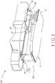
Fig. 2 is similar toFig. 1 but viewed from a bottom side; -
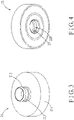
Fig. 3 is a perspective view of a male member of a locking mechanism used in the battery cartridge; -
Fig. 4 is a perspective view of a female member of the locking mechanism; -
Fig. 5 is a partial cross-sectional view of the locking mechanism; -
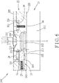
Fig. 6 is similar toFig. 5 but illustrating when a pressurized fluid is applied; -
Fig. 7 is a partial cross-sectional view similar toFig. 5 but illustrating another configuration of a retaining member in the female member of the locking mechanism; -
Fig. 8 is a schematic view illustrating relation among a pressurized-fluid source, a control member, and the locking mechanisms of the battery cartridge; -
Fig. 9 is a schematic view illustrating the vehicle in a ready position for exchanging the battery cartridge; and -
Fig. 10 is a block diagram illustrating a method for exchanging a first battery cartridge for a second battery cartridge according to an embodiment of the disclosure. - Referring to
Figs. 1 and2 , abattery cartridge 100 for avehicle 101 according to an embodiment of the disclosure is shown. Thevehicle 101 includes achassis 102 with alower chassis surface 103 and defines abattery accommodation compartment 104 which is open to thelower chassis surface 103. Although, in an embodiment shown inFigs. 1 and2 , thebattery accommodation compartment 104 is located on a bottom side of the vehicle, in other embodiments, the battery accommodation compartment may be located on a top side or a lateral side of the vehicle based on designs. - The
battery cartridge 100 includes acarrier frame 11, abattery assembly 12, and at least onelocking mechanism 200. - In an embodiment, the
battery cartridge 100 is a heavy-duty battery cartridge for an electric-powered vehicle. - The
carrier frame 11 includes an upper (first)frame surface 111. In an embodiment shown inFig. 1 , thefirst frame surface 111 has acentral region 112 and aperipheral region 113 around thecentral region 112. Theperipheral region 113 has afront area 114 and arear area 115. - The
battery assembly 12 is disposed on thefirst frame surface 111, and has a profile to be received in thebattery accommodation compartment 104 when thebattery cartridge 100 is disposed to be mounted to thechassis 102 of thevehicle 101. In an embodiment shown inFig. 1 , thebattery assembly 12 includes a plurality ofbattery modules 121, and is configured to be secured on thecentral region 112. - The
locking mechanism 200 is to be disposed between thelower chassis surface 103 of thevehicle 101 and thefirst frame surface 111 to permit thebattery cartridge 100 to be locked to thechassis 102 of thevehicle 101, and is configured such that when a pressure from a pressurized fluid is applied to thelocking mechanism 200, thebattery cartridge 100 is permitted to be unlocked from thechassis 102 of thevehicle 101. - In an embodiment, pressurized air is used to serve as the pressurized fluid. Alternatively, a hydraulic fluid may be used to serve as the pressurized fluid.
- In an embodiment shown in
Figs. 3 to 6 , thelocking mechanism 200 includes amale member 21, afemale member 22, and at least one retainingmember 23. - The
male member 21 includes abase body 211 and aplug 212. Thebase body 211 is to be mounted on the one of thelower chassis surface 103 of thevehicle 101 and thefirst frame surface 111. Theplug 212 extends from thebase body 211 along an axial axis (A), and has an outer peripheral surface which surrounds the axial axis (A) and which is formed with a retainedgroove 213. - In an embodiment shown in
Figs. 5 and6 , the retainedgroove 213 extends in a circumferential direction about the axial axis (A). - The
female member 22 is to be mounted on the other one of thelower chassis surface 103 of thevehicle 101 and thefirst frame surface 111, and has asocket hole 220 configured to permit insertion of theplug 212. Thefemale member 22 defines therein at least oneinner chamber 221 with afluid inlet 223 and afluid outlet 224. The pressurized fluid from a pressurized-fluid source 105 (only shown inFig. 8 ) is permitted to be introduced into theinner chamber 221 through thefluid inlet 223. The pressurized fluid is permitted to be discharged from theinner chamber 221 through thefluid outlet 224. Thefemale member 22 has at least onepassage 222 which is formed inside thesocket hole 220, and which extends radially to communicate with theinner chamber 221. - In an embodiment shown in
Figs. 1 to 6 , thebase body 211 of themale member 21 is mounted on theperipheral region 113 of thefirst frame surface 111. Thefemale member 22 has a firstmajor surface 225 which is to be mounted on thelower chassis surface 103 of thevehicle 101, and a secondmajor surface 226 which is opposite to the firstmajor surface 225 and which confronts thebase body 211. - The retaining
member 23 is disposed in thepassage 222, and is configured such that once theplug 212 is inserted into thesocket hole 220, theretaining member 23 is brought into retaining engagement with theplug 212, and such that once the pressurized fluid is introduced into theinner chamber 221, the retainingmember 23 is permitted to release from the retaining disengage with theplug 212. - In an embodiment shown in
Figs. 5 and6 , theretaining member 23 has afirst end 231 and asecond end 232 which are radially opposite to each other. Thefirst end 231 of the retainingmember 23 has a truncated wedge cross section. Alternatively, thefirst end 231 of the retainingmember 23 may have a V-shaped cross section shown inFig. 7 . - The retaining
member 23 is movable radially between an inward position and an outward position. In the inward position, as shown inFig. 5 , thefirst end 231 is engaged in the retainedgroove 213 of theplug 212 so as to retain theplug 212 inside thesocket hole 220 to thereby permit thebattery cartridge 100 to be locked to thechassis 102 of thevehicle 101. In the outward position, as shown inFig. 6 , thefirst end 231 is retracted in thepassage 222 so as to permit removal of theplug 212 from thesocket hole 220, to thereby allow thebattery cartridge 100 to be unlocked from thechassis 102 of thevehicle 101. In an embodiment shown inFigs. 5 and6 , the retainingmember 23 is elongated, and thesecond end 232 is disposed in theinner chamber 221. - In an embodiment shown in
Figs. 5 and6 , thelocking mechanism 200 further includes at least onepiston 24, at least oneactuator 25, and at least one first biasingmember 26. - The
piston 24 is disposed in theinner chamber 221, and is configured to be forced by the pressure from the pressurized fluid to shift from a first position to a second position. In the first position, as shown inFig. 5 , thefluid outlet 224 is not in fluid communication with thefluid inlet 223. In the second position, as shown inFig. 6 , thefluid outlet 224 is in fluid communication with thefluid inlet 223. - The
actuator 25 extends from thepiston 24 to move therewith, and is configured such that when thepiston 24 is displaced to the second position, theactuator 25 is moved with thepiston 24 to permit movement of the retainingmember 23 to the outward position. - The
first biasing member 26 is disposed in theinner chamber 221 to bias thepiston 24 to the first position. - In an embodiment shown in
Figs. 5 and6 , thelocking mechanism 200 further includes at least onesecond biasing member 27 which is disposed in theinner chamber 221 to bias the retainingmember 23 to the inward position so as to permit thefirst end 231 of the retainingmember 23 to be brought into clicking engagement with the retainedgroove 213 in response to insertion of theplug 212 into thesocket hole 220. - In an embodiment shown in
Figs. 5 and6 , theactuator 25 is coupled to anintermediate segment 233 of the retainingmember 23 between the first and second ends 231, 232 such that when thepiston 24 is displaced to the second position (Fig. 6 ), the retainingmember 23 is moved by theactuator 25 to the outward position against a biasing force of the second biasingmember 27. - In an embodiment shown in
Figs. 5 and6 , thefemale member 22 defines a plurality of theinner chambers 221 around the axial axis (A), and has a plurality of the passages 222 (only one is shown) displaced from each other about the axial axis (A). Thelocking mechanism 200 includes a plurality of the retaining members 23 (only one is shown) which are respectively disposed in thepassages 222, a plurality of thepistons 24 which are respectively disposed in theinner chambers 221, a plurality of the actuators 25 (only one is shown) which extend respectively from thepistons 24 to move therewith, a plurality of the first biasing members 26 (only one is shown) which are disposed respectively in theinner chambers 221 to respectively bias thepistons 24 to the first position (Fig. 5 ), and a plurality of the second biasing members 27 (only one is shown) which are disposed respectively in theinner chambers 221 to respectively bias the retainingmembers 23 to the inward position (Fig. 5 ). - In an embodiment shown in
Figs. 1 and2 , thebattery cartridge 100 includes a plurality of the lockingmechanisms 200, and a manifold 32 is provided inside thevehicle 101 to form afluid duct 107 so as to permit the pressurized fluid to be evenly distributed to the lockingmechanisms 200. Alternatively, the manifold 32 may be provided inside thecarrier frame 11. - The
base bodies 211 of themale members 21 of the lockingmechanisms 200 are mounted on the front andrear areas major surfaces 225 of thefemale members 22 are mounted on thelower chassis surface 103 of thevehicle 101 in positions corresponding to themale members 21. Here, the term "respectively" means that for each of the front andrear areas base bodies 211 of themale members 21 of the lockingmechanisms 200 is mounted thereon. -
Fig. 9 illustrates a method for exchanging afirst battery cartridge 100 of thevehicle 101 for asecond battery cartridge 100. The method includes steps (a) to (k). - In step (a), the first and
second battery cartridges 100 are provided. Each of the first andsecond battery cartridges 100, which is substantially the same as the above-mentionedbattery cartridge 100, is permitted to be locked to thechassis 102, and is configured such that once the pressure from the pressurized fluid is applied to the locking mechanism(s) 200, the first orsecond battery cartridge 100 is permitted to be unlocked from thechassis 102. - In step (b), as also shown in
Fig. 9 , aplatform 31 is placed beneath thecarrier frame 11 of thefirst battery cartridge 100 locked on thevehicle 101. - In step (c), the
platform 31 is jacked up to permit thefirst battery cartridge 100 to be held by theplatform 31. - In step (d), the pressure from the pressurized fluid is applied to the
locking mechanism 200 of thefirst battery cartridge 100 through thefluid duct 107 in thevehicle 101 until thefirst battery cartridge 100 is unlocked from thechassis 102. As illustrated inFig. 8 , acontrol member 106 may be disposed downstream of the pressurized-fluid source 105 and upstream of the lockingmechanisms 200 to control provision or interruption of the supply of the pressurized fluid. - In step (e), the
platform 31 and thechassis 102 are moved away from each other such that thefirst battery cartridge 100 is fully disposed beneath thechassis 102. - In step (f), the
platform 31, together with thefirst battery cartridge 100, is moved out of thevehicle 101. - In step (g), the
first battery cartridge 100 on theplatform 31 is exchanged for thesecond battery cartridge 100. - In step (h), the
platform 31, together with thesecond battery cartridge 100, is placed beneath thechassis 102. - In step (i), the
second battery cartridge 100 is aligned with thechassis 102 to permit thesecond battery cartridge 100 to be locked to thechassis 102. In other words, theplug 212 is aligned with the correspondingsocket hole 220. - In step (j), the
second battery cartridge 100 and thechassis 102 are moved toward each other until thesecond battery cartridge 100 is locked to thechassis 31. - In step (k), the
platform 31 is moved out of thevehicle 101. - In the description above, for the purposes of explanation, numerous specific details have been set forth in order to provide a thorough understanding of the embodiment (s). It will be apparent, however, to one skilled in the art, that one or more other embodiments may be practiced without some of these specific details. It should also be appreciated that reference throughout this specification to "one embodiment," "an embodiment," an embodiment with an indication of an ordinal number and so forth means that a particular feature, structure, or characteristic may be included in the practice of the disclosure. It should be further appreciated that in the description, various features are sometimes grouped together in a single embodiment, figure, or description thereof for the purpose of streamlining the disclosure and aiding in the understanding of various inventive aspects, and that one or more features or specific details from one embodiment may be practiced together with one or more features or specific details from another embodiment, where appropriate, in the practice of the disclosure.
Claims (7)
- A battery cartridge (100) for a vehicle (101) which defines a battery accommodation compartment (104), said battery cartridge (100) comprising:a carrier frame (11) including a first frame surface (111); anda battery assembly (12) disposed on said first frame surface (111), and having a profile to be received in the battery accommodation compartment (104) when said battery cartridge (100) is disposed to be mounted to the vehicle (101), said battery cartridge (100) being characterized by comprisingat least one locking mechanism (200) which is to be disposed between the vehicle (101) and said first frame surface (111) to permit said battery cartridge (100) to be locked to the vehicle (101), and which is configured such that when a pressure from a pressurized fluid is applied to said at least one locking mechanism (200), said battery cartridge (100) is permitted to be unlocked from the vehicle (101).
- The battery cartridge (100) according to claim 1, characterized in that said at least one locking mechanism (200) includesa male member (21) including a base body (211) which is to be mounted on one of the vehicle (101) and said first frame surface (111), and a plug (212) which extends from said base body (211) along an axial axis (A),a female member (22) which is to be mounted on the other one of the vehicle (101) and said first frame surface (111), and which has a socket hole (220) configured to permit insertion of said plug (212), said female member (22) defining therein at least one inner chamber (221) with a fluid inlet (223) through which the pressurized fluid from a pressurized-fluid source (105) is permitted to be introduced into said at least one inner chamber (221), and a fluid outlet (224) through which the pressurized fluid is permitted to be discharged from said at least one inner chamber (221), said female member (22) having at least one passage (222) which is formed inside said socket hole (220), and which extends radially to communicate with said at least one inner chamber (221), andat least one retaining member (23) disposed in said at least one passage (222), and configured such that once said plug (212) is inserted into said socket hole (220), said at least one retaining member (23) is brought into retaining engagement with said plug (212), and such that once the pressurized fluid is introduced into said_at least one inner chamber (221), said_at least one retaining member (23) is permitted to release from the retaining disengage with said plug (212).
- The battery cartridge (100) according to claim 2, characterized in thatsaid plug (212) has an outer peripheral surface which surrounds the axial axis (A) and which is formed with a retained groove (213); andsaid_at least one retaining member (23) has a first end (231) and a second end (232) which are radially opposite to each other, said_at least one retaining member (23) being movable radially between an inward position, where said first end (231) is engaged in said retained groove (213) of said plug (212) so as to retain said plug (212) inside said socket hole (220) to thereby permit said battery cartridge (100) to be locked to the vehicle (101), and an outward position, where said first end (231) is retracted in said_at least one passage (222) so as to permit removal of said plug (212) from said socket hole (220), to thereby allow said battery cartridge (100) to be unlocked from the vehicle (101).
- The battery cartridge (100) according to claim 3, characterized in that said at least one locking mechanism (200) further includesat least one piston (24) which is disposed in said_at least one inner chamber (221), and which is configured to be forced by the pressure from the pressurized fluid to shift from a first position, where said fluid outlet (224) is not in fluid communication with said fluid inlet (223), to a second position, where said fluid outlet (224) is in fluid communication with said fluid inlet (223),at least one actuator (25) extending from said piston (24) to move therewith, and configured such that when said piston (24) is displaced to the second position, said at least one actuator (25) is moved with said piston (24) to permit movement of said at least one retaining member (23) to the outward position, andat least one first biasing member (26) disposed in said inner chamber (221) to bias said piston (24) to the first position.
- The battery cartridge (100) according to anyone of claims 2 to 4, characterized in thatsaid first frame surface (111) has a central region (112) and a peripheral region (113) around said central region (112);said battery assembly (12) includes a plurality of battery modules (121), and is configured to be secured onto said central region (112);said base body (211) of said male member (21) is mounted on said peripheral region (113) of said first frame surface (111); andsaid female member (22) has a first major surface (225) which is to be mounted on the vehicle (101), and a second major surface (226) which is opposite to said first major surface (225) and which confronts said base body (211).
- The battery cartridge (100) according to claim 5, characterized in that said battery cartridge (100) comprises a plurality of said locking mechanisms (200).
- The battery cartridge (100) according to claim 6, characterized in that said peripheral region (113) has a front area (114) and a rear area (115), and said base bodies (211) of said male members (21) of said plurality of said locking mechanisms (200) are mounted on said front and rear areas (114, 115), respectively, said first major surfaces (225) of said female members (22) being mounted in positions corresponding to said male members (21).
Applications Claiming Priority (1)
| Application Number | Priority Date | Filing Date | Title |
|---|---|---|---|
| US16/391,568 US11056746B2 (en) | 2019-04-23 | 2019-04-23 | Battery cartridge for vehicle and locking mechanism |
Publications (2)
| Publication Number | Publication Date |
|---|---|
| EP3731303A1 EP3731303A1 (en) | 2020-10-28 |
| EP3731303B1 true EP3731303B1 (en) | 2022-06-22 |
Family
ID=70277297
Family Applications (1)
| Application Number | Title | Priority Date | Filing Date |
|---|---|---|---|
| EP20168916.3A Active EP3731303B1 (en) | 2019-04-23 | 2020-04-09 | Battery cartridge for vehicle |
Country Status (6)
| Country | Link |
|---|---|
| US (1) | US11056746B2 (en) |
| EP (1) | EP3731303B1 (en) |
| JP (1) | JP2020181812A (en) |
| KR (1) | KR20200124606A (en) |
| CN (1) | CN111823841B (en) |
| TW (1) | TWI745901B (en) |
Families Citing this family (1)
| Publication number | Priority date | Publication date | Assignee | Title |
|---|---|---|---|---|
| JP7431916B1 (en) | 2022-09-29 | 2024-02-15 | 日立建機株式会社 | construction machinery |
Family Cites Families (19)
| Publication number | Priority date | Publication date | Assignee | Title |
|---|---|---|---|---|
| IL116345A0 (en) * | 1995-12-12 | 1996-03-31 | Electric Fuel Ltd | A battery connector for use with an electric vehicle and a metal-air battery |
| US5799514A (en) * | 1997-03-25 | 1998-09-01 | American Handcuff Co. | Fluid actuated handcuff |
| JP3740405B2 (en) * | 2001-10-12 | 2006-02-01 | シーケーディ株式会社 | Air cylinder |
| US7249659B2 (en) * | 2004-01-08 | 2007-07-31 | New York Air Brake Corporation | Fluid actuator |
| US8006793B2 (en) | 2008-09-19 | 2011-08-30 | Better Place GmbH | Electric vehicle battery system |
| JP2010125867A (en) * | 2008-11-25 | 2010-06-10 | Nissan Motor Co Ltd | Battery fixing structure of electric powered vehicle |
| FR2954592B1 (en) * | 2009-12-21 | 2012-01-06 | Renault Sa | METHOD AND SYSTEM FOR MOUNTING OR DISASSEMBLING A BATTERY OF A MOTOR VEHICLE. |
| FR2958237B1 (en) * | 2010-04-06 | 2016-02-05 | Akka Ingenierie Produit | LOCKING SYSTEM FOR RACK BATTERIES OF ELECTRIC VEHICLE |
| CN202242931U (en) * | 2011-09-16 | 2012-05-30 | 湖州客车厂有限公司 | Assembly device of storage battery box of electric vehicle |
| CN102529667B (en) * | 2012-02-15 | 2015-09-02 | 亿源动力(北京)科技有限公司 | The blocking device of vehicle battery box |
| IL218870A0 (en) * | 2012-03-27 | 2012-06-28 | Better Place GmbH | Battery switch module |
| CN103373210B (en) * | 2012-04-24 | 2016-09-21 | 杭州市电力局 | A kind of batteries of electric automobile supporting mechanism and electric automobile |
| CN103022392B (en) * | 2012-12-11 | 2015-07-29 | 深圳哈维科技有限公司 | A kind of fast assembling-disassembling battery and two-wheel balance car |
| US10513247B2 (en) | 2013-06-19 | 2019-12-24 | Tesla, Inc. | Battery swapping system and techniques |
| US9969283B2 (en) * | 2013-09-10 | 2018-05-15 | General Electric Company | Battery changing system and method |
| FR3015774A1 (en) * | 2013-12-24 | 2015-06-26 | Commissariat Energie Atomique | REMOVABLE FIXING SYSTEM FOR A BATTERY WITH A SUPPORT |
| CN204641364U (en) * | 2015-05-19 | 2015-09-16 | 杨小丽 | Change the single-lift battery box structure of electric-type electronlmobil |
| DE102017216841A1 (en) * | 2017-09-22 | 2019-03-28 | Mahle International Gmbh | battery system |
| CN207303190U (en) * | 2017-09-30 | 2018-05-01 | 深圳市大疆创新科技有限公司 | Battery module and unmanned plane |
-
2019
- 2019-04-23 US US16/391,568 patent/US11056746B2/en active Active
-
2020
- 2020-03-24 TW TW109109747A patent/TWI745901B/en active
- 2020-04-09 EP EP20168916.3A patent/EP3731303B1/en active Active
- 2020-04-14 KR KR1020200045227A patent/KR20200124606A/en not_active Ceased
- 2020-04-17 CN CN202010304710.9A patent/CN111823841B/en active Active
- 2020-04-17 JP JP2020074219A patent/JP2020181812A/en active Pending
Also Published As
| Publication number | Publication date |
|---|---|
| US20200343500A1 (en) | 2020-10-29 |
| EP3731303A1 (en) | 2020-10-28 |
| CN111823841A (en) | 2020-10-27 |
| CN111823841B (en) | 2024-08-06 |
| JP2020181812A (en) | 2020-11-05 |
| TW202039282A (en) | 2020-11-01 |
| TWI745901B (en) | 2021-11-11 |
| US11056746B2 (en) | 2021-07-06 |
| KR20200124606A (en) | 2020-11-03 |
Similar Documents
| Publication | Publication Date | Title |
|---|---|---|
| EP1970170B1 (en) | Robot arm coupling device | |
| JP7167186B2 (en) | quick change transfer assembly | |
| EP3731303B1 (en) | Battery cartridge for vehicle | |
| EP2072233B1 (en) | Tire mold | |
| EP2324996B1 (en) | Segmented tire mold | |
| EP1764291B1 (en) | Automotive vehicle framing system | |
| GB1581484A (en) | Apparatus for making connections in pneumatic and hydraulic systems | |
| CN102806613B (en) | Mold for tire | |
| JP7420742B2 (en) | quick exchange tooling assembly | |
| GB2025308A (en) | Method of making tyres | |
| US4181482A (en) | Tire tread forming apparatus | |
| JP7445811B2 (en) | rotating manifold | |
| CN102123839A (en) | Mold having mold tooling | |
| JP7319300B2 (en) | process shaft tooling assembly | |
| US4063861A (en) | Tire mold | |
| EP2072235B1 (en) | Tire mold | |
| US7661943B2 (en) | Mold for vulcanizing an unvulcanized tire blank | |
| CN222245669U (en) | Tread mold and tire mold | |
| US9616535B2 (en) | Positioning device and positoning method using the same | |
| EP3013569B1 (en) | Tire mold with improved durability | |
| US4181488A (en) | Tire tread forming mold body | |
| CA1094765A (en) | Tire tread forming method and apparatus | |
| CN214263941U (en) | Chuck device | |
| US4152388A (en) | Tire tread forming method | |
| CN217914759U (en) | Tool clamp connecting device of polishing robot |
Legal Events
| Date | Code | Title | Description |
|---|---|---|---|
| PUAI | Public reference made under article 153(3) epc to a published international application that has entered the european phase |
Free format text: ORIGINAL CODE: 0009012 |
|
| STAA | Information on the status of an ep patent application or granted ep patent |
Free format text: STATUS: THE APPLICATION HAS BEEN PUBLISHED |
|
| AK | Designated contracting states |
Kind code of ref document: A1 Designated state(s): AL AT BE BG CH CY CZ DE DK EE ES FI FR GB GR HR HU IE IS IT LI LT LU LV MC MK MT NL NO PL PT RO RS SE SI SK SM TR |
|
| AX | Request for extension of the european patent |
Extension state: BA ME |
|
| STAA | Information on the status of an ep patent application or granted ep patent |
Free format text: STATUS: REQUEST FOR EXAMINATION WAS MADE |
|
| 17P | Request for examination filed |
Effective date: 20210428 |
|
| RBV | Designated contracting states (corrected) |
Designated state(s): AL AT BE BG CH CY CZ DE DK EE ES FI FR GB GR HR HU IE IS IT LI LT LU LV MC MK MT NL NO PL PT RO RS SE SI SK SM TR |
|
| REG | Reference to a national code |
Ref country code: DE Ref legal event code: R079 Ref document number: 602020003615 Country of ref document: DE Free format text: PREVIOUS MAIN CLASS: H01M0002100000 Ipc: H01M0050249000 |
|
| GRAP | Despatch of communication of intention to grant a patent |
Free format text: ORIGINAL CODE: EPIDOSNIGR1 |
|
| STAA | Information on the status of an ep patent application or granted ep patent |
Free format text: STATUS: GRANT OF PATENT IS INTENDED |
|
| RIC1 | Information provided on ipc code assigned before grant |
Ipc: H01M 50/249 20210101AFI20210816BHEP |
|
| INTG | Intention to grant announced |
Effective date: 20210917 |
|
| GRAJ | Information related to disapproval of communication of intention to grant by the applicant or resumption of examination proceedings by the epo deleted |
Free format text: ORIGINAL CODE: EPIDOSDIGR1 |
|
| STAA | Information on the status of an ep patent application or granted ep patent |
Free format text: STATUS: REQUEST FOR EXAMINATION WAS MADE |
|
| GRAP | Despatch of communication of intention to grant a patent |
Free format text: ORIGINAL CODE: EPIDOSNIGR1 |
|
| STAA | Information on the status of an ep patent application or granted ep patent |
Free format text: STATUS: GRANT OF PATENT IS INTENDED |
|
| INTC | Intention to grant announced (deleted) | ||
| INTG | Intention to grant announced |
Effective date: 20220215 |
|
| GRAS | Grant fee paid |
Free format text: ORIGINAL CODE: EPIDOSNIGR3 |
|
| GRAA | (expected) grant |
Free format text: ORIGINAL CODE: 0009210 |
|
| STAA | Information on the status of an ep patent application or granted ep patent |
Free format text: STATUS: THE PATENT HAS BEEN GRANTED |
|
| AK | Designated contracting states |
Kind code of ref document: B1 Designated state(s): AL AT BE BG CH CY CZ DE DK EE ES FI FR GB GR HR HU IE IS IT LI LT LU LV MC MK MT NL NO PL PT RO RS SE SI SK SM TR |
|
| REG | Reference to a national code |
Ref country code: GB Ref legal event code: FG4D |
|
| REG | Reference to a national code |
Ref country code: CH Ref legal event code: EP |
|
| REG | Reference to a national code |
Ref country code: DE Ref legal event code: R096 Ref document number: 602020003615 Country of ref document: DE |
|
| REG | Reference to a national code |
Ref country code: AT Ref legal event code: REF Ref document number: 1500380 Country of ref document: AT Kind code of ref document: T Effective date: 20220715 |
|
| REG | Reference to a national code |
Ref country code: IE Ref legal event code: FG4D |
|
| REG | Reference to a national code |
Ref country code: LT Ref legal event code: MG9D |
|
| REG | Reference to a national code |
Ref country code: NL Ref legal event code: MP Effective date: 20220622 |
|
| PG25 | Lapsed in a contracting state [announced via postgrant information from national office to epo] |
Ref country code: SE Free format text: LAPSE BECAUSE OF FAILURE TO SUBMIT A TRANSLATION OF THE DESCRIPTION OR TO PAY THE FEE WITHIN THE PRESCRIBED TIME-LIMIT Effective date: 20220622 Ref country code: NO Free format text: LAPSE BECAUSE OF FAILURE TO SUBMIT A TRANSLATION OF THE DESCRIPTION OR TO PAY THE FEE WITHIN THE PRESCRIBED TIME-LIMIT Effective date: 20220922 Ref country code: LT Free format text: LAPSE BECAUSE OF FAILURE TO SUBMIT A TRANSLATION OF THE DESCRIPTION OR TO PAY THE FEE WITHIN THE PRESCRIBED TIME-LIMIT Effective date: 20220622 Ref country code: HR Free format text: LAPSE BECAUSE OF FAILURE TO SUBMIT A TRANSLATION OF THE DESCRIPTION OR TO PAY THE FEE WITHIN THE PRESCRIBED TIME-LIMIT Effective date: 20220622 Ref country code: GR Free format text: LAPSE BECAUSE OF FAILURE TO SUBMIT A TRANSLATION OF THE DESCRIPTION OR TO PAY THE FEE WITHIN THE PRESCRIBED TIME-LIMIT Effective date: 20220923 Ref country code: FI Free format text: LAPSE BECAUSE OF FAILURE TO SUBMIT A TRANSLATION OF THE DESCRIPTION OR TO PAY THE FEE WITHIN THE PRESCRIBED TIME-LIMIT Effective date: 20220622 Ref country code: BG Free format text: LAPSE BECAUSE OF FAILURE TO SUBMIT A TRANSLATION OF THE DESCRIPTION OR TO PAY THE FEE WITHIN THE PRESCRIBED TIME-LIMIT Effective date: 20220922 |
|
| REG | Reference to a national code |
Ref country code: AT Ref legal event code: MK05 Ref document number: 1500380 Country of ref document: AT Kind code of ref document: T Effective date: 20220622 |
|
| PG25 | Lapsed in a contracting state [announced via postgrant information from national office to epo] |
Ref country code: RS Free format text: LAPSE BECAUSE OF FAILURE TO SUBMIT A TRANSLATION OF THE DESCRIPTION OR TO PAY THE FEE WITHIN THE PRESCRIBED TIME-LIMIT Effective date: 20220622 Ref country code: LV Free format text: LAPSE BECAUSE OF FAILURE TO SUBMIT A TRANSLATION OF THE DESCRIPTION OR TO PAY THE FEE WITHIN THE PRESCRIBED TIME-LIMIT Effective date: 20220622 |
|
| PG25 | Lapsed in a contracting state [announced via postgrant information from national office to epo] |
Ref country code: NL Free format text: LAPSE BECAUSE OF FAILURE TO SUBMIT A TRANSLATION OF THE DESCRIPTION OR TO PAY THE FEE WITHIN THE PRESCRIBED TIME-LIMIT Effective date: 20220622 |
|
| PG25 | Lapsed in a contracting state [announced via postgrant information from national office to epo] |
Ref country code: SM Free format text: LAPSE BECAUSE OF FAILURE TO SUBMIT A TRANSLATION OF THE DESCRIPTION OR TO PAY THE FEE WITHIN THE PRESCRIBED TIME-LIMIT Effective date: 20220622 Ref country code: SK Free format text: LAPSE BECAUSE OF FAILURE TO SUBMIT A TRANSLATION OF THE DESCRIPTION OR TO PAY THE FEE WITHIN THE PRESCRIBED TIME-LIMIT Effective date: 20220622 Ref country code: RO Free format text: LAPSE BECAUSE OF FAILURE TO SUBMIT A TRANSLATION OF THE DESCRIPTION OR TO PAY THE FEE WITHIN THE PRESCRIBED TIME-LIMIT Effective date: 20220622 Ref country code: PT Free format text: LAPSE BECAUSE OF FAILURE TO SUBMIT A TRANSLATION OF THE DESCRIPTION OR TO PAY THE FEE WITHIN THE PRESCRIBED TIME-LIMIT Effective date: 20221024 Ref country code: ES Free format text: LAPSE BECAUSE OF FAILURE TO SUBMIT A TRANSLATION OF THE DESCRIPTION OR TO PAY THE FEE WITHIN THE PRESCRIBED TIME-LIMIT Effective date: 20220622 Ref country code: EE Free format text: LAPSE BECAUSE OF FAILURE TO SUBMIT A TRANSLATION OF THE DESCRIPTION OR TO PAY THE FEE WITHIN THE PRESCRIBED TIME-LIMIT Effective date: 20220622 Ref country code: CZ Free format text: LAPSE BECAUSE OF FAILURE TO SUBMIT A TRANSLATION OF THE DESCRIPTION OR TO PAY THE FEE WITHIN THE PRESCRIBED TIME-LIMIT Effective date: 20220622 Ref country code: AT Free format text: LAPSE BECAUSE OF FAILURE TO SUBMIT A TRANSLATION OF THE DESCRIPTION OR TO PAY THE FEE WITHIN THE PRESCRIBED TIME-LIMIT Effective date: 20220622 |
|
| PG25 | Lapsed in a contracting state [announced via postgrant information from national office to epo] |
Ref country code: PL Free format text: LAPSE BECAUSE OF FAILURE TO SUBMIT A TRANSLATION OF THE DESCRIPTION OR TO PAY THE FEE WITHIN THE PRESCRIBED TIME-LIMIT Effective date: 20220622 Ref country code: IS Free format text: LAPSE BECAUSE OF FAILURE TO SUBMIT A TRANSLATION OF THE DESCRIPTION OR TO PAY THE FEE WITHIN THE PRESCRIBED TIME-LIMIT Effective date: 20221022 |
|
| REG | Reference to a national code |
Ref country code: DE Ref legal event code: R097 Ref document number: 602020003615 Country of ref document: DE |
|
| PG25 | Lapsed in a contracting state [announced via postgrant information from national office to epo] |
Ref country code: AL Free format text: LAPSE BECAUSE OF FAILURE TO SUBMIT A TRANSLATION OF THE DESCRIPTION OR TO PAY THE FEE WITHIN THE PRESCRIBED TIME-LIMIT Effective date: 20220622 |
|
| PG25 | Lapsed in a contracting state [announced via postgrant information from national office to epo] |
Ref country code: DK Free format text: LAPSE BECAUSE OF FAILURE TO SUBMIT A TRANSLATION OF THE DESCRIPTION OR TO PAY THE FEE WITHIN THE PRESCRIBED TIME-LIMIT Effective date: 20220622 |
|
| PLBE | No opposition filed within time limit |
Free format text: ORIGINAL CODE: 0009261 |
|
| STAA | Information on the status of an ep patent application or granted ep patent |
Free format text: STATUS: NO OPPOSITION FILED WITHIN TIME LIMIT |
|
| 26N | No opposition filed |
Effective date: 20230323 |
|
| PG25 | Lapsed in a contracting state [announced via postgrant information from national office to epo] |
Ref country code: SI Free format text: LAPSE BECAUSE OF FAILURE TO SUBMIT A TRANSLATION OF THE DESCRIPTION OR TO PAY THE FEE WITHIN THE PRESCRIBED TIME-LIMIT Effective date: 20220622 |
|
| REG | Reference to a national code |
Ref country code: CH Ref legal event code: PL |
|
| PG25 | Lapsed in a contracting state [announced via postgrant information from national office to epo] |
Ref country code: LU Free format text: LAPSE BECAUSE OF NON-PAYMENT OF DUE FEES Effective date: 20230409 |
|
| REG | Reference to a national code |
Ref country code: BE Ref legal event code: MM Effective date: 20230430 |
|
| PG25 | Lapsed in a contracting state [announced via postgrant information from national office to epo] |
Ref country code: MC Free format text: LAPSE BECAUSE OF FAILURE TO SUBMIT A TRANSLATION OF THE DESCRIPTION OR TO PAY THE FEE WITHIN THE PRESCRIBED TIME-LIMIT Effective date: 20220622 |
|
| PG25 | Lapsed in a contracting state [announced via postgrant information from national office to epo] |
Ref country code: MC Free format text: LAPSE BECAUSE OF FAILURE TO SUBMIT A TRANSLATION OF THE DESCRIPTION OR TO PAY THE FEE WITHIN THE PRESCRIBED TIME-LIMIT Effective date: 20220622 Ref country code: LI Free format text: LAPSE BECAUSE OF NON-PAYMENT OF DUE FEES Effective date: 20230430 Ref country code: IT Free format text: LAPSE BECAUSE OF FAILURE TO SUBMIT A TRANSLATION OF THE DESCRIPTION OR TO PAY THE FEE WITHIN THE PRESCRIBED TIME-LIMIT Effective date: 20220622 Ref country code: CH Free format text: LAPSE BECAUSE OF NON-PAYMENT OF DUE FEES Effective date: 20230430 |
|
| REG | Reference to a national code |
Ref country code: IE Ref legal event code: MM4A |
|
| PG25 | Lapsed in a contracting state [announced via postgrant information from national office to epo] |
Ref country code: BE Free format text: LAPSE BECAUSE OF NON-PAYMENT OF DUE FEES Effective date: 20230430 |
|
| PG25 | Lapsed in a contracting state [announced via postgrant information from national office to epo] |
Ref country code: IE Free format text: LAPSE BECAUSE OF NON-PAYMENT OF DUE FEES Effective date: 20230409 |
|
| PG25 | Lapsed in a contracting state [announced via postgrant information from national office to epo] |
Ref country code: IE Free format text: LAPSE BECAUSE OF NON-PAYMENT OF DUE FEES Effective date: 20230409 |
|
| PG25 | Lapsed in a contracting state [announced via postgrant information from national office to epo] |
Ref country code: BG Free format text: LAPSE BECAUSE OF FAILURE TO SUBMIT A TRANSLATION OF THE DESCRIPTION OR TO PAY THE FEE WITHIN THE PRESCRIBED TIME-LIMIT Effective date: 20220622 |
|
| PG25 | Lapsed in a contracting state [announced via postgrant information from national office to epo] |
Ref country code: BG Free format text: LAPSE BECAUSE OF FAILURE TO SUBMIT A TRANSLATION OF THE DESCRIPTION OR TO PAY THE FEE WITHIN THE PRESCRIBED TIME-LIMIT Effective date: 20220622 |
|
| PGFP | Annual fee paid to national office [announced via postgrant information from national office to epo] |
Ref country code: DE Payment date: 20250428 Year of fee payment: 6 |
|
| PG25 | Lapsed in a contracting state [announced via postgrant information from national office to epo] |
Ref country code: CY Free format text: LAPSE BECAUSE OF FAILURE TO SUBMIT A TRANSLATION OF THE DESCRIPTION OR TO PAY THE FEE WITHIN THE PRESCRIBED TIME-LIMIT; INVALID AB INITIO Effective date: 20200409 |
|
| PG25 | Lapsed in a contracting state [announced via postgrant information from national office to epo] |
Ref country code: HU Free format text: LAPSE BECAUSE OF FAILURE TO SUBMIT A TRANSLATION OF THE DESCRIPTION OR TO PAY THE FEE WITHIN THE PRESCRIBED TIME-LIMIT; INVALID AB INITIO Effective date: 20200409 |
|
| PG25 | Lapsed in a contracting state [announced via postgrant information from national office to epo] |
Ref country code: TR Free format text: LAPSE BECAUSE OF FAILURE TO SUBMIT A TRANSLATION OF THE DESCRIPTION OR TO PAY THE FEE WITHIN THE PRESCRIBED TIME-LIMIT Effective date: 20220622 |
|
| REG | Reference to a national code |
Ref country code: DE Ref legal event code: R082 Ref document number: 602020003615 Country of ref document: DE Representative=s name: WESTPHAL, MUSSGNUG & PARTNER PATENTANWAELTE MI, DE |
|
| PGFP | Annual fee paid to national office [announced via postgrant information from national office to epo] |
Ref country code: GB Payment date: 20260202 Year of fee payment: 7 |
|
| PGFP | Annual fee paid to national office [announced via postgrant information from national office to epo] |
Ref country code: FR Payment date: 20260210 Year of fee payment: 7 |