EP3731068A1 - Information processing system, information processing method, and program - Google Patents
Information processing system, information processing method, and program Download PDFInfo
- Publication number
- EP3731068A1 EP3731068A1 EP18891566.4A EP18891566A EP3731068A1 EP 3731068 A1 EP3731068 A1 EP 3731068A1 EP 18891566 A EP18891566 A EP 18891566A EP 3731068 A1 EP3731068 A1 EP 3731068A1
- Authority
- EP
- European Patent Office
- Prior art keywords
- display surface
- display
- information
- transfer
- predetermined
- Prior art date
- Legal status (The legal status is an assumption and is not a legal conclusion. Google has not performed a legal analysis and makes no representation as to the accuracy of the status listed.)
- Withdrawn
Links
Images


Classifications
-
- G—PHYSICS
- G06—COMPUTING; CALCULATING OR COUNTING
- G06F—ELECTRIC DIGITAL DATA PROCESSING
- G06F3/00—Input arrangements for transferring data to be processed into a form capable of being handled by the computer; Output arrangements for transferring data from processing unit to output unit, e.g. interface arrangements
- G06F3/01—Input arrangements or combined input and output arrangements for interaction between user and computer
- G06F3/017—Gesture based interaction, e.g. based on a set of recognized hand gestures
-
- G—PHYSICS
- G06—COMPUTING; CALCULATING OR COUNTING
- G06F—ELECTRIC DIGITAL DATA PROCESSING
- G06F3/00—Input arrangements for transferring data to be processed into a form capable of being handled by the computer; Output arrangements for transferring data from processing unit to output unit, e.g. interface arrangements
- G06F3/01—Input arrangements or combined input and output arrangements for interaction between user and computer
- G06F3/048—Interaction techniques based on graphical user interfaces [GUI]
- G06F3/0487—Interaction techniques based on graphical user interfaces [GUI] using specific features provided by the input device, e.g. functions controlled by the rotation of a mouse with dual sensing arrangements, or of the nature of the input device, e.g. tap gestures based on pressure sensed by a digitiser
- G06F3/0488—Interaction techniques based on graphical user interfaces [GUI] using specific features provided by the input device, e.g. functions controlled by the rotation of a mouse with dual sensing arrangements, or of the nature of the input device, e.g. tap gestures based on pressure sensed by a digitiser using a touch-screen or digitiser, e.g. input of commands through traced gestures
-
- G—PHYSICS
- G06—COMPUTING; CALCULATING OR COUNTING
- G06F—ELECTRIC DIGITAL DATA PROCESSING
- G06F3/00—Input arrangements for transferring data to be processed into a form capable of being handled by the computer; Output arrangements for transferring data from processing unit to output unit, e.g. interface arrangements
- G06F3/01—Input arrangements or combined input and output arrangements for interaction between user and computer
- G06F3/011—Arrangements for interaction with the human body, e.g. for user immersion in virtual reality
-
- G—PHYSICS
- G06—COMPUTING; CALCULATING OR COUNTING
- G06F—ELECTRIC DIGITAL DATA PROCESSING
- G06F3/00—Input arrangements for transferring data to be processed into a form capable of being handled by the computer; Output arrangements for transferring data from processing unit to output unit, e.g. interface arrangements
- G06F3/01—Input arrangements or combined input and output arrangements for interaction between user and computer
- G06F3/03—Arrangements for converting the position or the displacement of a member into a coded form
- G06F3/041—Digitisers, e.g. for touch screens or touch pads, characterised by the transducing means
- G06F3/042—Digitisers, e.g. for touch screens or touch pads, characterised by the transducing means by opto-electronic means
- G06F3/0425—Digitisers, e.g. for touch screens or touch pads, characterised by the transducing means by opto-electronic means using a single imaging device like a video camera for tracking the absolute position of a single or a plurality of objects with respect to an imaged reference surface, e.g. video camera imaging a display or a projection screen, a table or a wall surface, on which a computer generated image is displayed or projected
-
- G—PHYSICS
- G06—COMPUTING; CALCULATING OR COUNTING
- G06F—ELECTRIC DIGITAL DATA PROCESSING
- G06F3/00—Input arrangements for transferring data to be processed into a form capable of being handled by the computer; Output arrangements for transferring data from processing unit to output unit, e.g. interface arrangements
- G06F3/01—Input arrangements or combined input and output arrangements for interaction between user and computer
- G06F3/048—Interaction techniques based on graphical user interfaces [GUI]
- G06F3/0484—Interaction techniques based on graphical user interfaces [GUI] for the control of specific functions or operations, e.g. selecting or manipulating an object, an image or a displayed text element, setting a parameter value or selecting a range
- G06F3/0486—Drag-and-drop
-
- G—PHYSICS
- G09—EDUCATION; CRYPTOGRAPHY; DISPLAY; ADVERTISING; SEALS
- G09G—ARRANGEMENTS OR CIRCUITS FOR CONTROL OF INDICATING DEVICES USING STATIC MEANS TO PRESENT VARIABLE INFORMATION
- G09G5/00—Control arrangements or circuits for visual indicators common to cathode-ray tube indicators and other visual indicators
- G09G5/003—Details of a display terminal, the details relating to the control arrangement of the display terminal and to the interfaces thereto
-
- G—PHYSICS
- G06—COMPUTING; CALCULATING OR COUNTING
- G06F—ELECTRIC DIGITAL DATA PROCESSING
- G06F2203/00—Indexing scheme relating to G06F3/00 - G06F3/048
- G06F2203/038—Indexing scheme relating to G06F3/038
- G06F2203/0383—Remote input, i.e. interface arrangements in which the signals generated by a pointing device are transmitted to a PC at a remote location, e.g. to a PC in a LAN
-
- G—PHYSICS
- G09—EDUCATION; CRYPTOGRAPHY; DISPLAY; ADVERTISING; SEALS
- G09G—ARRANGEMENTS OR CIRCUITS FOR CONTROL OF INDICATING DEVICES USING STATIC MEANS TO PRESENT VARIABLE INFORMATION
- G09G2340/00—Aspects of display data processing
-
- G—PHYSICS
- G09—EDUCATION; CRYPTOGRAPHY; DISPLAY; ADVERTISING; SEALS
- G09G—ARRANGEMENTS OR CIRCUITS FOR CONTROL OF INDICATING DEVICES USING STATIC MEANS TO PRESENT VARIABLE INFORMATION
- G09G2354/00—Aspects of interface with display user
Definitions
- the present disclosure relates to an information processing system, an information processing method, and a program.
- AR augmented reality
- Patent Literature 1 describes a technology for detecting a marker by analyzing a captured image and calling a function associated with the detected marker.
- Patent Literature 1 JP 2015-90524 A
- Patent Literature 1 when an operation of moving an object in a certain display surface with respect to a transfer object is detected, it is not considered to adaptively control the display on the display surface in response to the operation.
- the present disclosure provides a new and improved information processing system, information processing method, and program capable of adaptively controlling a display on the display surface in response to an operation of moving an object in a certain display surface with respect to a transfer object.
- an information processing system includes: a processing unit that performs, on a first display surface, a predetermined display control indicating that one or more pieces of display information in a second display surface corresponding to the first display surface is changed to be operable in the first display surface when a first operation for a first user to move a first object to a detection area having a predetermined positional relationship with one or more predetermined transfer objects positioned in the first display surface, and changes a display state of the second display surface based on a detection result of a second operation by the first user after the first operation.
- an information processing method includes: performing, on a first display surface, a predetermined display control indicating that one or more pieces of display information in a second display surface corresponding to the first display surface is changed to be operable in the first display surface when a first operation for a first user to move a first object to a detection area having a predetermined positional relationship with one or more predetermined transfer objects positioned in the first display surface; and changing, by a processor, a display state of the second display surface based on a detection result of a second operation by the first user after the detection of the first operation.
- a program executes a computer to function as a processing unit that performs, on a first display surface, a predetermined display control indicating that one or more pieces of display information in a second display surface corresponding to the first display surface is changed to be operable in the first display surface when a first operation for a first user to move a first object to a detection area having a predetermined positional relationship with one or more predetermined transfer objects positioned in the first display surface, and changes a display state of the second display surface based on a detection result of a second operation by the first user after the detection of the first operation.
- a plurality of components having substantially the same functional configuration may be distinguished by adding different alphabets after the same reference numeral.
- a plurality of components having substantially the same functional configuration are distinguished as necessary, such as a table 90a and a table 90b.
- the components are denoted by only the same reference numeral.
- the table 90a and the table 90b are simply referred to as a table 90.
- the system can mean a configuration for executing predetermined processing.
- the system may be constituted by one device, or may be constituted by a plurality of devices.
- the information processing system 10 according to the present embodiment may also be configured to be able to execute predetermined processing as a whole, and may be arbitrary which configuration in the information processing system 10 is regarded as one device.
- FIG. 1 is a diagram illustrating a configuration example of the information processing system 10.
- an information processing system 10a according to the present embodiment includes an input unit 120a and an output unit 124a.
- An output unit 124a can be configured to include an output device 162 described later.
- the output unit 124a displays various information on a table 90a.
- the output unit 124a can be a projection unit (projector).
- the output unit 124a can be arranged above the table 90a at a predetermined distance from the table 90a while being suspended from a ceiling.
- the output unit 124a can project information on a top surface of the table 90a.
- the output unit 124a may be a pendant light or a desk stand light.
- Such a method of displaying information on a top surface of a table 90a from above is also referred to as "projection type".
- the top surface of the table 90 may be referred to as display surface 20.
- the display surface 20 includes a surface (screen) to be projected by an output unit 124.
- the output unit 124a displays a virtual display object according to control of a display processing unit 122 described later.
- the display object is, for example, a window, a user interface (UI) object, or the like.
- the UI object is a predetermined image (still image or moving image) that receives various operations (selection, input, or the like) by a user.
- the UI object is an image including graphical user interface (GUI) components (for example, a button, a slider, a check box, a text box, a software keyboard, and the like).
- GUI graphical user interface
- the UI object can be arranged in the window.
- An input unit 120a can be configured to include an input device 160 described later.
- the input unit 120a includes, for example, a camera that captures an image of the table 90a with one lens.
- the input unit 120a can include a stereo camera capable of recording information in a depth direction by capturing the image of the table 90a with two lenses.
- the stereo camera for example, a visible light camera, an invisible light camera capable of detecting invisible light such as infrared light, or the like can be used.
- the input unit 120a can further include a voice input device such as a microphone that collects a voice uttered by a user or environmental sound of the surrounding environment.
- the information processing system 10a analyzes an image (captured image) captured by the camera, thereby detecting a position of an object (for example, a user's hand or the like) positioned on the display surface 20.
- an object for example, a user's hand or the like
- the term "hand” can be mainly used as an expression meaning a hand itself.
- the present invention is not limited to such an example, and this description may be used as an expression meaning a finger, an arm, or two or more (for example, an upper limb or the like) of these parts.
- the information processing system 10a analyzes the image captured by the stereo camera, thereby acquiring depth information of the object in addition to position information of an object positioned on the display surface 20.
- the information processing system 10a can detect touch or approach of the user's hand to the display surface 20 and separation of the hand from the display surface 20, based on the depth information.
- the input unit 120a may have another type of depth sensor (for example, a time-of-flight type sensor, a structured light type sensor, or the like) instead of the stereo camera. In this case, the depth sensor can acquire the depth information of the object positioned on the display surface 20.
- a position of an operation tool (for example, a user's hand, various operating members such as a stylus) on the display surface 20 can be detected based on an image captured by the input unit 120a, and various information can be input based on the detected position of the operation tool. That is, the user can perform various operation inputs by moving the operation tool on the display surface 20. For example, the touch of the user's hand to the window or the UI object is detected, and as a result, the operation input to the window or the UI object is performed.
- an operation tool for example, a user's hand, various operating members such as a stylus
- the camera included in the input unit 120a can not only photograph the top surface of the table 90a, but also photograph a user existing around the table 90a.
- the information processing system 10a can detect the position of the user around the table 90a based on the image captured by the input unit 120a.
- the information processing system 10a may perform personal recognition of a user by detecting physical characteristics (such as a size of a face or a body) of each user based on the captured image.
- an operation input of a user is not limited to the example described above, and may be executed by another method.
- the input unit 120a may be arranged as a touch panel on the top surface (display surface 20a) of the table 90a, and the operation input of the user may also be detected by a touch of the user's finger or the like on the touch panel.
- a gesture operation of the user may be photographed by a camera included in the input unit 120a, and the operation input of the user may be detected based on the photographed image.
- the configuration of the information processing system 10a according to the present embodiment has been described above. Note that the configuration of the information processing system 10 according to the present embodiment is not limited to the example illustrated in FIG. 1 .
- the information processing system 10 may have another configuration as illustrated in FIGS. 2 to 4 , for example.
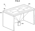
- FIG. 2 is a diagram illustrating another configuration example (information processing system 10b) of the information processing system 10 according to the present embodiment.
- the output unit 124b is arranged below the table 90b.
- the output unit 124b is, for example, a projector, and projects information from below the table 90b toward a tabletop of the table 90b.
- the tabletop of the table 90b is formed of a transparent material such as a glass plate or a transparent plastic plate.
- the information projected by the output unit 124b is displayed on the top surface (display surface 20b) of the table 90b (through the tabletop).
- the method of displaying information on the display surface 20b by projecting the information from below the table 90b to the output unit 124b in this way is also referred to as "rear projection type".
- the input unit 120b is provided on the display surface 20b.
- the input unit 120b is constituted by a touch panel.
- the touch of the operation tool to the display surface 20b is detected by the touch panel, so that the operation input of the user can be received.
- the present invention is not limited to such an example, and the input unit 120b may be arranged below the table 90b while being separated from the table 90b, similarly to the information processing system 10a illustrated in FIG. 2 .
- the input unit 120b can include a camera, and the camera can photograph the operation tool positioned on the display surface 20b over the tabletop of the table 90b. Then, the position of the operation tool can be detected based on the photographed image.
- FIG. 3 is a diagram illustrating still another configuration example (information processing system 10c) of the information processing system 10 according to the present embodiment.
- a touch panel type display is arranged on the table 90c with the display surface facing upward.
- the input unit 120c and the output unit 124c can be integrally configured as the touch panel type display.
- various information can be displayed on a display screen (display surface 20c) of the display, and the operation input of the user can be received by detecting the touch of the operation tool on the display screen of the display by the touch panel.
- the camera an example of the input unit 120c
- the output unit 124c may be arranged above the output unit 124c, as in the information processing system 10a illustrated in FIG. 1 .
- individual users positioned around the table 90c can be detected based on the image photographed by the camera.
- FIG. 4 is a diagram illustrating yet another configuration example (information processing system 10d) of the information processing system 10 according to the present embodiment.
- the information processing system 10d can be constituted as a head mounted type device (for example, a glasses type device or the like) such as a head mounted display (HMD)).
- the head mounted type device can include the input unit 120d (not illustrated) and the output unit 124d (not illustrated).
- the output unit 124d may be constituted as a transmission type display device.
- the output unit 124d can project an image to at least some areas of each of a right-eye lens and a left-eye lens (or goggle type lens), that are included in the head mounted type device, as a projection surface (display surface 20d).
- the output unit 124d may be constituted as a non-transmission type display device.
- the output unit 124d can be configured to include a liquid crystal display (LCD), an organic light emitting diode (OLED), or the like.
- the input unit 120d can include a camera. In this case, the camera may photograph an image in front of a user wearing the head mounted type device, and the output unit 124d may sequentially display the photographed image. Thereby, the user can see a scene in front of the user via an image displayed on the output unit 124d.
- FIG. 5 is a diagram illustrating a configuration example of the system.
- any one of the information processing systems 10a to 10d described above and one or more different display surfaces 20 may be connected via, for example, a communication network 22.
- the other display surface 20 may be, for example, a whiteboard, a top surface of the table such as the display surface 20a or the display surface 20b, a predetermined device such as the display surface 20c, or a predetermined surface such as the display surface 20d included in the head mounted type device.
- the communication network 22 is a wired or wireless transmission path of information transmitted from a device connected to the communication network 22.
- the communication network 22 may include a public line network such as a telephone line network, the Internet, and a satellite communication network, various local area networks (LANs) including Ethernet (registered trademark), a wide area network (WAN), and the like.
- LANs local area networks
- WAN wide area network
- the communication network 22 may include a dedicated line network such as an internet protocol-virtual private network (IP-VPN).
- IP-VPN internet protocol-virtual private network
- the configuration of the information processing system 10 according to the present embodiment has been described above. As will be described later, according to the present embodiment, in a scene in which information corresponding to an object positioned in a certain display surface is transferred to another display surface, among all objects positioned in the display surface of the transfer source, only information corresponding to an object selected by the user can be displayed on the display surface of the transfer destination.
- FIG. 6 is a block diagram illustrating an example of a functional configuration of the information processing system 10.
- the information processing system 10 includes a processing unit 100, the input unit 120, the display processing unit 122, the output unit 124, and a storage unit 126.
- description of the same contents as those described above will be omitted.
- the display processing unit 122 can be configured to include one or a plurality of processing circuits (for example, a central processing unit (CPU), a graphics processing unit (GPU), or the like).
- the display processing unit 122 performs processing related to graphics that can be displayed by the output unit 124, based on input information acquired by the input unit 120. For example, the display processing unit 122 performs drawing processing of a display object such as a window, and outputs the processed result to the output unit 124. As an example, the display processing unit 122 performs the drawing processing of these display objects according to a user operation on individual display objects.
- the display processing unit 122 can acquire the input information (for example, a captured image, or the like) acquired by the input unit 120 from the input unit 120, and output the input information to the processing unit 100. Further, the display processing unit 122 can also receive the information processed by the processing unit 100 from the processing unit 100, and perform the drawing processing based on the information.
- the input information for example, a captured image, or the like
- the display processing unit 122 can also receive the information processed by the processing unit 100 from the processing unit 100, and perform the drawing processing based on the information.
- the processing unit 100 can be configured to include one or a plurality of processing circuits (for example, a CPU 150, a GPU, or the like described below). The processing unit 100 performs various processing based on the input information acquired by the input unit 120.
- the processing unit 100 has a transfer operation detection unit 102, a surface attribute matching processing unit 104, and a display control unit 106.
- the transfer operation detection unit 102 detects a transfer operation for transferring one object positioned in the display surface 20-1 to another display surface 20-2 based on the input information acquired from the input unit 120. For example, when an operation (for example, approach) for a certain user to move one object positioned on the display surface 20-1 to a detection area having a predetermined positional relationship with one or more predetermined transfer objects positioned in the display surface 20-1 is detected, the transfer operation detection unit 102 detects the operation as the transfer operation.
- the detection area may be the same as the predetermined transfer object.
- the detection area may be an area that includes all or some of the object areas where the predetermined transfer object is positioned on the display surface 20-1 and is within a predetermined distance from a contour of the object area. Note that the "transfer area" described later is an example of the detection area.
- the transfer operation is an example of a first operation according to the present disclosure.
- the predetermined transfer object may be a predetermined real object (for example, a predetermined transfer base 32 or the like as illustrated in FIG. 7 ) or a predetermined display object.
- the transfer operation detection unit 102 may detect the operation as the transfer operation.
- the processing unit 100 can set, for example, a circular transfer area 34 around the transfer base 32, and display the transfer area 34 on the display surface 20-1.
- the transfer operation detection unit 102 may detect the operation as the transfer operation.
- the transfer area 34 is an example of the above detection area. Note that the present embodiment is not limited to the example illustrated in FIG. 7 , and the processing unit 100 may set the transfer area 34 in a location where the transfer base 32 is not arranged.
- the surface attribute matching processing unit 104 determines display setting of information corresponding to the object to be transferred, which is displayed on the display surface of the transfer destination, based on the information associated with the display surface of the transfer destination and the information associated with the display surface of the transfer source. For example, the surface attribute matching processing unit 104 determines the display setting of the object to be transferred information, which is displayed on the display surface of the transfer destination, based on the information associated with the display surface of the transfer destination that is stored in the surface attribute information DB 128 as illustrated in FIG. 8 .
- the display setting of the information of the object to be transferred can include, for example, a display size, a display direction, a display content, and the like of the information in the display surface of the corresponding transfer destination.
- the display surface before the transfer is an example of the first display surface according to the present disclosure.
- the display surface of the transfer destination is an example of the second display surface according to the present disclosure.
- the surface attribute information DB 128 is a database that stores information (attribute information and the like) associated with each display surface.
- the information associated with the display surface for example, screen characteristics (for example, physical size, resolution, aspect ratio, and the like) of the display surface, and layout characteristics (for example, direction of gravity with respect to the display surface, and the like) of the relevant display surface.
- the surface attribute information DB 128 can be implemented, for example, in a form such as a relational database or a lookup table.
- FIG. 8 is a diagram illustrating a configuration example of the surface attribute information DB 128.
- the surface attribute information DB 128 for example, No. 1280, a type of surface 1282, a direction of gravity 1284, a size 1286, a resolution 1288, and a surface attribute matching process 1290 are associated.
- the type of surface 1282 stores a type of the corresponding display surface.
- the direction of gravity 1284 stores a direction of gravity with respect to the corresponding display surface. For example, when the corresponding display surface is a vertically arranged plane, the direction of gravity 1284 stores "downward".
- the display direction of the image is automatically determined based on the information stored in the direction of gravity 1284.
- the size 1286 stores a size of the display surface.
- the resolution 1288 stores a resolution of the display surface.
- the surface attribute matching process 1290 stores contents of predetermined processing for matching the information to the display surface.
- FIG. 9A is a diagram illustrating a configuration example of the display surface 20-1 (table surface 20-1) in which No. in the surface attribute information DB 128 illustrated in FIG. 8 is "1"
- FIG. 9B is a diagram illustrating a configuration example of the display surface 20-2 (whiteboard 20-2) in which No. in the surface attribute information DB 128 illustrated in FIG. 8 is "2".
- FIGS. 9A and 9B are diagram illustrating a configuration example of the display surface 20-1 (table surface 20-1) in which No. in the surface attribute information DB 128 illustrated in FIG. 8 is "1"
- FIG. 9B is a diagram illustrating a configuration example of the display surface 20-2 (whiteboard 20-2) in which No. in the surface attribute information DB 128 illustrated in FIG. 8 is "2".
- the table surface 20-1 has a width of 120 cm and a height of 80 cm, and, for example, an image having a resolution of 1366 ⁇ 768 is projected to the table surface 20-1 by the output unit 124.
- the tag 30 having a size of 200 pixels square is arranged on the table surface 20-1.
- the whiteboard 20-2 has a width of 100 cm and a height of 190 cm, and, for example, an image having a resolution of 2160 ⁇ 3840 is projected by a projector corresponding to the whiteboard 20-2.
- the surface attribute matching processing unit 104 may determine to increase the size of the image corresponding to the tag 30 according to a difference between dots per inch (dpi) (specifically 29 dpi) of the table surface 20-1 that is the surface of the transfer source, and dpi (specifically 51 dpi) of the whiteboard 20-2 that is the surface of the transfer destination.
- dpi dots per inch
- an image 40b of the determined size can be displayed on the whiteboard 20-2 under the control of the display control unit 106 described later.
- the tag 30 can be displayed even on the whiteboard 20-2 in full size. Therefore, a user using the table surface 20-1 and a user using the whiteboard 20-2 can more smoothly perform communication (discussion and the like) associated with the tag 30.
- FIGS. 10A and 10B are diagrams illustrating an example in which the image corresponding to the tag 30 on the table surface 20-1 is transferred to the whiteboard 20-2 and displayed.
- the table surface 20-1 is a horizontally arranged plane
- the whiteboard 20-2 is a vertically arranged plane.
- the direction of gravity is not set on the table surface 20-1, and the "downward" is set on the whiteboard 20-2 as the direction of gravity.
- the surface attribute matching processing unit 104 determines the display direction of the image 40 (tag image 40) corresponding to the tag 30 as, for example, the "downward" in the whiteboard 20-2, based on the information of the "direction of gravity" associated with the whiteboard 20-2 in the surface attribute information DB 128. Thereby, as illustrated in FIG. 10B , the tag image 40 can be displayed on the whiteboard 20-2 in the determined display direction.
- the display control unit 106 controls display of various types of information on the output unit 124.
- the display control unit 106 can control the information corresponding to the object to be transferred to be displayed on the display surface of the transfer destination. For example, when the transfer operation is detected, the display control unit 106 displays the image corresponding to the corresponding object to be transferred on the display surface of the transfer destination with the display setting determined by the surface attribute matching processing unit 104. For example, when the transfer operation is detected, the display control unit 106 displays the image corresponding to the corresponding object to be transferred in the transfer area set in the display surface of the transfer destination with the display setting determined by the surface attribute matching processing unit 104.
- the storage unit 126 can be configured to include a storage device 164 described later.
- the storage unit 126 stores various data such as the surface attribute information DB 128 and various software.
- FIGS. 11 and 12 are flowcharts each illustrating a part of the processing flow according to the present embodiment. As illustrated in FIG. 11 , unless a user's end operation is detected (S101: No), the processing unit 100 repeats steps of S103 to S129 described below. When it is detected that the user has performed the end operation (S101: Yes), the processing flow ends.
- the processing unit 100 acquires the input information (various sensing results and the like) acquired by the input unit 120 from the input unit 120 (S103).
- the processing unit 100 controls outputs of various types of information by the output unit 124 to the display surface 20 (hereinafter, sometimes referred to as the display surface of the transfer source) corresponding to the output unit 124, based on the input information acquired in S103 (S105). For example, the processing unit 100 determines the operation contents (for example, whether or not the operation contents are a drag operation and the like) of the user based on the movement of the user's hand indicated by the acquired input information.
- the operation contents for example, whether or not the operation contents are a drag operation and the like
- the processing unit 100 compares a position (for example, coordinates) indicated by the drag operation in the display surface of the transfer source with positions (for example, coordinates) of each object positioned on the display surface of the transfer source, thereby determining whether or not the drag operation indicates any object on the display surface of the transfer source. Then, when it is detected that the drag operation indicates any object, the processing unit 100 can change the display position of the object according to the drag operation.
- the transfer operation detection unit 102 determines whether or not a transfer operation is performed on any object in the display surface of the transfer source based on the information acquired by the input unit 120 (S107). While the transfer operation is not detected (S107: No), the processing unit 100 performs steps after the S101 again.
- the surface attribute matching processing unit 104 extracts the attribute information of the display surface of the transfer destination from the surface attribute information DB 128 (S109). Then, the surface attribute matching processing unit 104 determines the display setting of the information corresponding to the object to be transferred, which is displayed on the display surface of the transfer destination, based on the extracted attribute information (Sill).
- the display control unit 106 first acquires one or more pieces of display information currently displayed on the display surface of the transfer destination, for example, from the display surface of the transfer destination. Then, the display control unit 106 controls the output unit 124 so that the acquired one or more pieces of display information are displayed on the display surface of the transfer source (S123).
- the input unit 120 acquires the information on the operation input of the user for the display surface of the transfer source (S125).
- the display control unit 106 determines whether or not the transfer position of the object to be transferred on the display surface of the transfer destination is determined based on the input information acquired in S125 (S127). When the transfer position of the object to be transferred is not determined (S127: No), the display control unit 106 performs steps after S123 again.
- the display control unit 106 displays the information (such as an image) corresponding to the object to be transferred at the determined transfer position in the display surface of the transfer destination (S129).
- processing unit 100 repeats steps after S101 again.
- the processing unit 100 displays the information corresponding to the object on the display surface of the transfer destination. Therefore, in the scene in which information corresponding to a certain object positioned on a certain display surface is transferred to another display surface, among all objects positioned in the display surface of the transfer source, only information corresponding to an object selected by the user can be displayed on the display surface of the transfer destination.
- a plurality of users positioned around the display surface of the transfer source have a sporadic discussion, and only objects (for example, tags and the like) corresponding to good opinions obtained as a result of the discussion can be seamlessly intensive on the display surface of the transfer destination. Then, during the discussion, a task of arranging objects corresponding to good opinions and objects corresponding to bad opinions becomes easy. Therefore, the plurality of users can continue the discussion without stopping the flow of creating ideas.
- the object to be transferred can be appropriately displayed on the display surface of the transfer destination according to the attribute information of the display surface of the transfer destination.
- communication discussed and the like
- the object to be transferred can be more smoothly performed between the user using the display surface of the transfer source and the user using the display surface of the transfer destination.
- the present embodiment is not limited to the above-described example, and various application examples are applicable.
- application examples of the present embodiment will be described in "3-1. First Application Example” to "3-13. Thirteenth Application Example”.
- each component included in the information processing system 10 according to each application example is the same as the example illustrated in FIG. 6 .
- Only components having functions different from those of the above-described embodiment will be described, and description of the same contents will be omitted.
- a display surface of a transfer destination of an object to be transferred can be determined adaptively to a state of a plurality of predetermined transfer objects positioned on a display surface of a transfer source.
- the plurality of predetermined transfer objects are real objects.
- a transfer operation detection unit 102 When it is detected that a user places a certain object, which is positioned on the display surface of the transfer source, on one of the plurality of predetermined transfer objects, a transfer operation detection unit 102 according to the first application example detects the operation as a transfer operation for transferring information corresponding to the object to another display surface.
- a display control unit 106 determines at least one display surface serving as a transfer destination of information corresponding to the object to be transferred from among a plurality of display surfaces corresponding to the display surface of the transfer source based on information indicating a state of a plurality of predetermined transfer objects positioned on the display surface of the transfer source and a detection result of the transfer operation. For example, each of the plurality of predetermined transfer objects is associated with one display surface different from each other among the plurality of display surfaces.
- the display control unit 106 determines at least one display surface serving as the transfer destination of the information corresponding to the object to be transferred based on whether a distance between any two transfer objects of the plurality of predetermined transfer objects is equal to or less than a predetermined threshold and whether an arrangement of any two transfer objects is a predetermined arrangement.
- a transfer base 32a of the two transfer bases 32 is associated with a whiteboard 20-2
- a transfer base 32b is associated with a whiteboard 20-3.
- the whiteboard 20-2 is a display surface used by a plurality of users belonging to group A for discussion.
- the whiteboard 20-3 is a display surface used by a plurality of users belonging to group B for discussion.
- the transfer base 32 illustrated in FIGS. 13 and 14 is an example of the above-described predetermined transfer object.
- two transfer bases 32 are arranged apart from each other on the display surface 20-1 (table surface 20-1) of the transfer source by a distance larger than a predetermined distance. Then, as illustrated in FIG. 13 , the user using the table surface 20-1 places the tag 30 on the transfer base 32b, as the transfer operation of the image corresponding to the tag 30 positioned on the table surface 20-1. In this case, as illustrated in FIG. 13 , the display control unit 106 transfers and displays an image 40 corresponding to the tag 30 only to the whiteboard 20-3 associated with the transfer base 32b of the two whiteboards.
- FIG. 14 it is assumed that two transfer bases 32 are adjacently arranged on the display surface 20-1 (table surface 20-1) of the transfer source. Then, the user using the table surface 20-1 places the tag 30 on the transfer base 32b, as the transfer operation of the image corresponding to the tag 30 positioned on the table surface 20-1 (as in the example illustrated in FIG. 13 ). In this case, as illustrated in FIG. 14 , the display control unit 106 transfers and displays the image 40 corresponding to the tag 30 only to both of the two whiteboards.
- a display surface of a transfer destination of an object to be transferred can be determined adaptively to postures of a predetermined transfer object positioned on a display surface of a transfer source.
- the predetermined transfer object is a real object having a plurality of surfaces as illustrated in FIG. 15 . Furthermore, it is assumed that each of the plurality of surfaces of the predetermined transfer object is associated with a different display surface among the plurality of display surfaces other than the display surface of the transfer source.
- the transfer operation detection unit 102 When it is detected that a user mounts a certain object, which is positioned on the display surface of the transfer source, on any of a plurality of surfaces having the predetermined transfer objects, the transfer operation detection unit 102 according to the first application example detects the operation as a transfer operation for transferring information corresponding to the object to another display surface.
- the display control unit 106 determines one display surface associated with a surface on which the object to be transferred is arranged among the plurality of surfaces having the predetermined transfer object as the display surface of the transfer destination of the information corresponding to the object.
- each of the plurality of surfaces of the transfer base 32 is associated with a different display surface among a plurality of display surfaces (for example, whiteboard 20-2 and whiteboard 20-3).
- a surface described as "A" among the plurality of surfaces of the transfer base 32 is associated with the whiteboard 20-2.
- a surface described as "B" among the plurality of surfaces is associated with the whiteboard 20-3.
- the transfer base 32 illustrated in FIGS. 15 and 16 is an example of the above-described predetermined transfer object.
- the transfer base 32 is arranged on the table surface 20-1 (that is, a surface associated with the whiteboard 20-2) so that an upper surface of the transfer base 32 is the surface described as "A". Then, the user using the table surface 20-1 places the tag 30 on the upper surface of the transfer base 32, as the transfer operation of the image corresponding to the tag 30 positioned on the table surface 20-1. In this case, as illustrated in FIG. 15 , the display control unit 106 transfers and displays an image 40 corresponding to the tag 30 only to the whiteboard 20-2 (associated with the surface described as "A") among the two whiteboards.
- the transfer base 32 is arranged on the table surface 20-1 so that an upper surface of the transfer base 32 is a surface described as "B" (that is, a surface associated with the whiteboard 20-3). Then, the user using the table surface 20-1 places the tag 30 on the upper surface of the transfer base 32, as the transfer operation of the image corresponding to the tag 30 positioned on the table surface 20-1. In this case, as illustrated in FIG. 16 , the display control unit 106 transfers and displays an image 40 corresponding to the tag 30 only to the whiteboard 20-3 (associated with the surface described as "B") among the two whiteboards.
- the display surface of the transfer destination of the object to be transferred can be determined adaptively in a direction in which the predetermined transfer object positioned on the display surface of the transfer source is directed.
- the predetermined transfer object is a real object having at least one inclined surface, for example, as illustrated in FIGS. 17 and 18 .
- the transfer operation detection unit 102 When it is detected that the user arranges a certain object on any of at least one inclined surface of the predetermined transfer object, the transfer operation detection unit 102 according to the third application example detects the operation as the transfer operation for transferring the information corresponding to the object to another display surface.
- the display control unit 106 determines, for example, the display surface positioned in the direction in which the predetermined transfer object is directed as the display surface of the transfer destination of the information corresponding to the objected to be transferred, from among the plurality of display surfaces corresponding to the display surface of the transfer source.
- the transfer base 32 has only one inclined surface.
- the information processing system 10 can specify a positional relationship between the table surface 20-1, the whiteboard 20-2, and the whiteboard 20-3 in real time.
- the processing unit 100 can acquire information indicating relative directions of the whiteboard 20-2 and the whiteboard 20-3 with respect to the table surface 20-1 in real time.
- the transfer base 32 illustrated in FIGS. 17 and 18 is an example of the above-described predetermined transfer object.
- the transfer base 32 is arranged on the table surface 20-1 in the state in which the transfer base 32 is directed in the direction of the whiteboard 20-2 with respect to the table surface 20-1. Then, the user using the table surface 20-1 places the tag 30 on the inclined surface of the transfer base 32, as the transfer operation of the image corresponding to the tag 30 positioned on the table surface 20-1. In this case, as illustrated in FIG. 17 , the display control unit 106 transfers and displays the image 40 corresponding to the tag 30 only to the whiteboard 20-2 in which the transfer base 32 is directed among the two whiteboards.
- the transfer base 32 is arranged on the table surface 20-1 in the state in which the transfer base 32 is directed in the direction of the whiteboard 20-3 with respect to the table surface 20-1. Then, the user using the table surface 20-1 places the tag 30 on the inclined surface of the transfer base 32, as the transfer operation of the image corresponding to the tag 30 positioned on the table surface 20-1. In this case, as illustrated in FIG. 18 , the display control unit 106 transfers and displays the image 40 corresponding to the tag 30 only to the whiteboard 20-3 in which the transfer base 32 is directed among the two whiteboards.
- an images corresponding to an object to be transferred can be displayed on a display surface of a transfer destination, adaptively to a relationship between a display surface of a transfer source and a posture of a predetermined transfer object.
- the predetermined transfer object is a real object is assumed.
- the transfer operation detection unit 102 When it is determined that an operation for a user to make a certain object approach and touch (for example, be arranged on) the predetermined transfer object arranged on the display surface of the transfer source, the transfer operation detection unit 102 according to the fourth application example detects this series of operations as a transfer operation for transferring information corresponding to the object to another display surface.
- the display control unit 106 controls an image corresponding to the object to be transferred to be displayed on a display surface of a transfer destination based on a detection result of a moving progress of the object to be transferred during the transfer operation and a detection result of a posture of the predetermined transfer object during the transfer operation. For example, in this case, when the image corresponding to the object to be transferred is displayed on the display surface of the transfer destination, the display control unit 106 continuously changes the display position of the image based on the detection result of the moving progress of the object to be transferred during the transfer operation and the detection result of the posture of the predetermined transfer object during the transfer operation.
- FIGS. 19A and 19B it is assumed that the same transfer base 32 is arranged on the display surface 20-1 (table surface 20-1) of the transfer source and the display surface 20-2 (table surface 20-2) of the transfer destination, respectively. Note that the transfer base 32 illustrated in FIGS. 19A and 19B is an example of the above-described predetermined transfer object.
- the user using the table surface 20-1 makes the tag 30 approach the transfer base 32a on the table surface 20-1 (transfer operation of the image corresponding to the tag 30) by a flick operation and arranges the tag 30 on the transfer base 32a.
- the display control unit 106 displays the image 40 corresponding to the tag 30 at the position of the transfer base 32b on the table surface 20-2.
- the display control unit 106 continuously changes the display position of the image 40 based on the relationship between the position and posture of the transfer base 32a on the table surface 20-1 and the position and posture of the transfer base 32b on the table surface 20-2 so that the image 40 moves relatively identically with the moving progress (for example, change in speed during movement, change in acceleration during movement, movement path, and the like) of the tag 30 with respect to the transfer base 32a during the transfer operation.
- the moving progress for example, change in speed during movement, change in acceleration during movement, movement path, and the like
- a character string included in an object to be transferred can be adaptively converted into a location (or a user who uses the display surface of the transfer destination) where a display surface of a transfer destination is positioned and displayed.
- the display control unit 106 When the transfer operation is detected by the transfer operation detection unit 102, the display control unit 106 according to the fifth application example generates an image corresponding to the object to be transferred and displays the image on the display surface of the transfer destination based on a conversion rule of the character string registered in the surface attribute information DB 128 in association with the display surface of the transfer destination. For example, the display control unit 106 first converts the character string included in the object to be transferred using the conversion rule of the character string registered in the surface attribute information DB 128 in association with the display surface of the transfer destination. Then, the display control unit 106 generates the image corresponding to the object to be transferred so as to include the converted character string (instead of the character string included in the object to be transferred).
- FIG. 20 is a diagram illustrating a configuration example of the surface attribute information DB 128 according to the fifth application example.
- a translation rule of the character string included in the object at the time of displaying the image corresponding to the object to be transferred can be predefined for each type of display surface.
- FIG. 21A is a diagram schematically illustrating the display surface 20-1 (table surface 20-1) in which No. in the surface attribute information DB 128 illustrated in FIG. 20 is "1".
- FIG. 21B is a diagram schematically illustrating the display surface 20-2 (table surface 20-2) in which No. in the surface attribute information DB 128 illustrated in FIG. 8 is "2".
- a scene is assumed in which one or more users using the display surface 20-1 positioned in the United States of America and one or more users using the display surface 20-2 positioned in Japan are brainstorming.
- the display control unit 106 first specifies all the character strings included in the tag 30a by using, for example, optical character recognition (OCR) and the like.
- OCR optical character recognition
- the display control unit 106 converts all the character strings included in tag 30a into Japanese based on the translation rule stored in the surface attribute information DB 128 in association with the display surface 20-2 (which is the display surface of the transfer destination of the image corresponding to the tag 30a).
- the display control unit 106 generates the image 40 corresponding to the tag 30a so as to include the converted character string (that is, Japanese character string).
- the display control unit 106 displays the image 40 on the transfer area 34b defined in the display surface 20-2.
- a character string included in an object to be transferred can be adaptively converted into a location (or a user who uses the display surface of the transfer destination) where a display surface of a transfer destination is positioned and displayed.
- FIG. 22 is a diagram illustrating a configuration example of a system according to the sixth application example.
- the system further includes a smartphone 50 as compared with the configuration example of the system according to the above-described embodiment illustrated in FIG. 5 , for example.
- the smartphone 50 is configured to be connectable to a communication network 22 by wireless communication.
- the smartphone 50 can transmit and receive various types of information to and from the information processing system 10 or other display surfaces (the display surface 20-2 and the display surface 20-3) via the communication network 22.
- the transfer operation detection unit 102 detects the operation of the user as the transfer operation for transferring the object from the smartphone 50 to another display surface.
- the display control unit 106 When the transfer operation on the smartphone 50 is detected by the transfer operation detection unit 102, the display control unit 106 according to the sixth application example generates an image corresponding to the object to be transferred and displays the image on the display surface of the transfer destination based on a conversion rule of the character string registered in the surface attribute information DB 128 in association with the display surface of the transfer destination.
- FIG. 23 is a diagram illustrating a configuration example of the surface attribute information DB 128 according to the sixth application example.
- FIG. 24A is a diagram schematically illustrating the display surface (that is, display surface of the smartphone 50) in which No. in the surface attribute information DB 128 illustrated in FIG. 23 is "1".
- FIG. 24B is a diagram schematically illustrating the display surface 20-2 (notice board 20-2) in which No. in the surface attribute information DB 128 illustrated in FIG. 23 is "2".
- FIG. 24C is a diagram schematically illustrating the display surface 20-2 (notice board 20-3) in which No. in the surface attribute information DB 128 illustrated in FIG.
- the smartphone 50 is used by a father of a certain family, the notice board 20-2 is placed in a living room of a house where the family lives, and the notice board 20-3 is placed in a children's room of the house.
- the conversion rule of the character string included in the object at the time of displaying the image corresponding to the object to be transferred can be predefined for each type of display surface. It is assumed that an adult user (for example, a mother) using the notice board 20-2 can easily understand the character string even if the character string includes Chinese character. Therefore, in the surface attribute information DB 128, "not converting the character string included in the object to be transferred" is associated with the notice board 20-2 as the conversion rule of the character string. On the other hand, it is assumed that a child using the notice board 20-3 has difficulty in understanding the character string when the character string includes Chinese character. Therefore, in the surface attribute information DB 128, "converting the character string included in the object to be transferred to Hiragana" is associated with the notice board 20-3 as the conversion rule of the character string.
- the tag 30 includes a character string including Chinese character ("back soon").
- the display control unit 106 of the information processing system 10 first specifies the character string included in the tag 30 based on the detection result of the operation received from the smartphone 50.
- the display control unit 106 determines not to convert the character string included in the tag 30 by referring to the conversion rule stored in the surface attribute information DB 128 in association with the notice board 20-2.
- the display control unit 106 generates an image 40a corresponding to the tag 30 including the character string included in the tag 30 as it is.
- the display control unit 106 displays the image 40a on the notice board 20-2.
- the display control unit 106 determines to convert all the character strings included in the tag 30 into "Hiragana” by referring to the conversion rule stored in the surface attribute information DB 128 in association with the notice board 20-3. Next, the display control unit 106 generates an image 40b corresponding to the tag 30 so as to include the converted character string. Then, as illustrated in FIG. 24C , the display control unit 106 displays the image 40b on the notice board 20-3.
- a format (or layout) of an image corresponding to an object to be transferred can be adaptively converted and displayed on a display surface of a transfer destination.
- a display control unit 106 When a transfer operation is detected by a transfer operation detection unit 102, a display control unit 106 according to the seventh application example first determines a format of an image corresponding to the object to be transferred based on a conversion rule of a format (or layout) of an image registered in a surface attribute information DB 128 in association with a display surface of a transfer destination. Then, the display control unit 106 displays the image of the determined format on the display surface of the transfer destination as an image corresponding to the object.
- FIG. 25 is a diagram illustrating a configuration example of the surface attribute information DB 128 according to the seventh application example.
- a conversion rule of a format (or layout) of an image corresponding to the object at the time of displaying the image corresponding to the object to be transferred can be predefined for each type of display surface.
- FIG. 26A is a diagram schematically illustrating the display surface 20-1 (table surface 20-1) in which No. in the surface attribute information DB 128 illustrated in FIG. 25 is "1".
- FIG. 26B is a diagram schematically illustrating the display surface 20-2 (notice board 20-2) in which No. in the surface attribute information DB 128 illustrated in FIG. 25 is "2".
- the display control unit 106 first refers to the conversion rule of the format that is stored in the surface attribute information DB 128 in association with the notice board 20-2 (which is the display surface of the transfer destination of the image corresponding to the two tags 30). Next, the display control unit 106 determine to convert shapes of images corresponding to each tag 30 into shapes of "posts", respectively, and convert "stamps" included in each tag 30 into “medal marks", respectively.
- the display control unit 106 converts each format of each tag 30 by the conversion rule determined for each tag 30, respectively, to generate each image 40 (image 40a and image 40b) corresponding to each tag 30. Then, as illustrated in FIG. 26B , the display control unit 106 displays the image 40a and the image 40b on the notice board 20-2.
- the image of the "post” including the same number of “medal marks” as the number of "stamps” (which was a measure of importance on the table surface 20-1) can be displayed on the notice board 20-2 as the image 40 corresponding to the tag 30.
- the seventh application example has been described above.
- an eighth application example according to the present embodiment will be described.
- the user using the display surface of the transfer source can display the image corresponding to the object to be transferred at a desired position in the display surface of the transfer destination by an intuitive operation.
- the display control unit 106 When the transfer operation is detected by the transfer operation detection unit 102, the display control unit 106 according to the eighth application example performs, on the display surface of the transfer source, the predetermined display control indicating that the display information displayed on the display surface of the transfer destination is changed to be operable in the display surface of the transfer source. For example, the display control unit 106 displays, on the display surface of the transfer source, one or more pieces of display information in a target area on the display surface of the transfer destination as the predetermined display control.
- the target area can be a partial area in the display surface of the transfer destination.
- the display control unit 106 when it is detected that a predetermined operation (hereinafter, sometimes referred to as a "subsequent operation") is performed following the transfer operation, the display control unit 106 first changes the target area from the predetermined area in the display surface of the transfer destination to another area corresponding to the detection result of the subsequent operation. Then, each time the target area is changed to another area, the display control unit 106 controls one or more pieces of display information in another area after the change as the display information in the display surface of the transfer destination displayed in the display surface of the transfer source to be sequentially displayed on the display surface of the transfer source.
- a predetermined operation hereinafter, sometimes referred to as a "subsequent operation”
- the subsequent operation is an example of a second operation according to the present disclosure.
- the subsequent operation can be an operation performed continuously on the transfer operation while maintaining the operation state for the object to be transferred in the predetermined operation state.
- the transfer operation can be an operation of dragging the object to be transferred on the display surface of the transfer source to the predetermined transfer object.
- the subsequent operation may be an operation of continuously dragging the object while maintaining a state (for example, a state in which the object is touched) in which the object is pointed.
- the second operation according to the present disclosure is not limited to the "subsequent operation" described above, and may be another type of operation performed by the user after the transfer operation.
- the second operation may be an operation for the user to move the object to be transferred on the display surface of the transfer source after the information corresponding to the object to be transferred is transferred.
- the second operation may be an operation for the user to flick the object to be transferred on the display surface of the transfer source to the predetermined transfer object (for example, transfer base and the like).
- the predetermined display control may change a display mode of the display surface of the transfer source.
- the predetermined display control may change a display color or luminance of the display surface of the transfer source, or to additionally display a predetermined effect on the display surface of the transfer source.
- the display control unit 106 can change the display state of the display surface of the transfer destination based on the detection result of the subsequent operation. For example, the display control unit 106 displays the information corresponding to the object to be transferred on the display surface of the transfer destination based on the detection result of the subsequent operation. As an example, the display control unit 106 determines the display position of the image corresponding to the object to be transferred in the display surface of the transfer destination based on the detection result of the subsequent operation.
- the subsequent operation may be a touch operation (drag operation and the like) for the object to be transferred.
- the display control unit 106 displays the image corresponding to the object to be transferred at a position on the display surface of the transfer destination corresponding to the position touched immediately before the timing.
- FIGS. 27A to 27D are diagrams illustrating examples of the display control on the display surface 20-1 (table surface 20-1) of the transfer source and the display surface 20-2 (whiteboard 20-2) of the transfer destination according to the eighth application example.
- the user using the table surface 20-1 drags the tag 30 from the outside of the transfer area 34a displayed on the table surface 20-1 (as the transfer operation of the image corresponding to the tag 30) into the transfer area 34a with his/her hand, and releases his/her hand from the tag 30.
- the display control unit 106 displays the image 40 corresponding to the tag 30 in the transfer area 34b set on the whiteboard 20-2.
- the display control unit 106 displays, on the table surface 20-1, all display information positioned within a clipping area 60 defined in the whiteboard 20-2.
- a clipping area 60 is an example of a target area.
- the display control unit 106 displays a display (for example, a contour line and the like of the clipping area 60) indicating the clipping area 60 to be displayed on the whiteboard 20-2 in real time. Furthermore, the display control unit 106 displays an image 62 indicating a pointing position of the user at a position in the whiteboard 20-2 corresponding to the current position (pointing position) of the hand during the drag operation in the table surface 20-1. For example, each time the pointing position of the user is changed, the display control unit 106 sequentially changes the display position of the image 62 in the whiteboard 20-2.
- a display for example, a contour line and the like of the clipping area 60
- the display control unit 106 transfers the image 40 corresponding to the tag 30 to the whiteboard 20-2. Then, the display control unit 106 displays the tag image 40 at the position of the whiteboard 20-2 corresponding to the position of the tag 30 on the table surface 20-1 at the timing when a hand is released from the tag 30.
- the display control unit 106 returns the display state of the table surface 20-1 to an original display state. That is, instead of the display information in the clipping area 60, the display control unit 106 displays the display information displayed on the table surface 20-1 to be displayed on the table surface 20-1 again, for example, when the subsequent operation is detected.
- the user using the display surface of the transfer source can display the image corresponding to the object to be transferred at a desired position in the display surface of the transfer destination. Further, the user can determine the transfer position (display position) of the image corresponding to the object to be transferred on the display surface of the transfer destination by an intuitive operation such as a drag operation.
- the eighth application example has been described above. Next, a ninth application example according to the present embodiment will be described. According to the ninth application example, the user can easily scroll the target area defined on the display surface of the transfer destination.
- the display control unit 106 moves the position of the target area in the display surface of the transfer destination based on the detection result of the subsequent operation while the state in which the user is pointing to the object to be transferred is maintained.
- FIGS. 28A and 28B the above functions will be described in more detail with reference to FIGS. 28A and 28B .
- FIG. 28A for example, as illustrated in FIG. 27C , it is assumed that the user using the table surface 20-1 drags the tag 30 into the transfer area 34a and then drags the tag 30 in the table surface 20-1 without releasing the hand from the tag 30.
- FIG. 28A it is assumed that an operation of sliding a left hand 4b on the table surface 20-1 is performed, for example, in a state in which for the left hand 4b is opened while maintaining the state in which the user touches the tag 30 with right hand 4a (that is, hand dragging the tag 30) on table surface 20-1.
- the display control unit 106 continuously moves the position of the clipping area 60 in the whiteboard 20-2 according to the detection result of the movement (the moving distance and the moving direction) of the left hand 4b. That is, the display control unit 106 scrolls the clipping area 60 according to the detection result of the movement of the left hand 4b.
- FIGS. 29A and 29B Next, another specific example of the above functions will be described in more detail with reference to FIGS. 29A and 29B .
- the user using the table surface 20-1 (similar to the example illustrated in FIG. 28A ) drags the tag 30 into the transfer area 34a and then drags the tag 30 in the table surface 20-1 without releasing the hand from the tag 30.
- the display control unit 106 continuously scrolls the clipping area 60 in the whiteboard 20-2 according to the position of the right hand 4a on the table surface 20-1.
- the display control unit 106 continuously scrolls the clipping area 60 to the direction of the whiteboard 20-2 corresponding to the direction in which the right hand 4a is dragged on the table surface 20-1.
- the user can easily change the clipping area 60 (that is, target area) in the display surface of the transfer destination, so the transfer position of the object to be transferred can be more easily determined. Therefore, even if the size of the display surface of the transfer source is significantly different from the size of the display surface of the transfer destination, the user can easily determine the transfer position of the object to be transferred.
- the clipping area 60 that is, target area
- an image indicating substantially the entire display surface of the transfer destination can be simultaneously displayed on the display surface of the transfer source, together with one or more pieces of display information within the target area on the display surface of the transfer destination.
- the display control unit 106 displays a map image indicating all the display information displayed on almost the entire display surface of transfer destination on the display surface of the transfer source during the subsequent operation (that is, while the state in which the user is pointing to object to be transferred is maintained). For example, the display control unit 106 displays the map image in a smaller size than the display surface of the transfer source at a predetermined position in the display surface of the transfer source.
- the display control unit 106 displays a map image 42 indicating all the display information displayed on substantially the entire display surface 20-2 of the transfer destination at a predetermined position in the display surface 20-1 of the transfer source during the scrolling of the clipping area 60 (that is, while the position of the clipping area 60 continuously moves).
- the map image 42 may include a display indicating the current clipping area 60.
- the user can grasp the positional relationship between the position of the current clipping area 60 and the entire display surface of the transfer destination in real time and easily.
- the display control unit 106 displays one or more pieces of display information on the display surface of the transfer destination and an operation image for moving the target area on the display surface of the transfer source during the subsequent operation (that is, while the state where the corresponding user is pointing to the object to be transferred is maintained).
- FIG. 31A is a diagram illustrating a display example of the display surface 20-2 of the transfer destination at a certain timing.
- FIG. 31B is a diagram illustrating an example in which the display information included in the clipping area 60 set on the display surface 20-2 of the transfer destination is displayed on the display surface 20-1 of the transfer source as illustrated in FIG. 31A .
- the display control unit 106 displays all the display information 40 included in the clipping area 60, and a plurality of scroll buttons 44 for scrolling the clipping area 60 in different directions on the display surface 20-1 of the transfer source. For example, the user can scroll the clipping area 60 in a direction corresponding to the scroll button 44 by touching each scroll button 44.
- the display control unit 106 may further display an image 46 indicating the direction of the transfer area defined on the display surface 20-2 of the transfer destination on the display surface 20-1 of the transfer source. According to the display example, for example, even when the user moves the clipping area 60, the user can grasp the positional relationship between the current position of the clipping area 60 and the entire display surface of the transfer destination in real time and easily.
- each user positioned at a different location from each other which is remote from a location where a certain display surface is positioned, can easily perform co-editing on one or more pieces of display information displayed on a display surface.
- the display surface 20-2 can be a display surface to be co-edited by one or more users using a display surface 20-1 and one or more users using a display surface 20-3.
- a display control unit 106 can display, on the display surface 20-1, a positional relationship between a first target area in the display surface 20-2 and a second target area in the display surface 20-2 while one or more pieces of the display information in the first target area in the display surface 20-2 are displayed on the display surface 20-1.
- the display control unit 106 can display, on the display surface 20-3, a positional relationship between the first target area and the second target area while one or more pieces of display information within the second target area in the display surface 20-2 are displayed on the display surface 20-3.
- the information processing system 10 can receive, from the display surface 20-3, second edition operation information of one or more users who are using the display surface 20-3, with respect to one or more pieces of display information within the second target area displayed on the display surface 20-3.
- the display control unit 106 displays the operation content indicated by the second editing operation information on the display surface 20-1.
- the display control unit 106 can acquire the first editing operation information of one or more users who are using the display surface 20-1 for one or more pieces of display information in the first target area, and the operation content indicated by the first editing operation information can be displayed on the display surface 20-3.
- FIGS. 32A to 32C the whiteboard 20-2, the table surface 20-1, and the table surface 20-3 are positioned remote from each other. Then, all display information within the clipping area 60a in the whiteboard 20-2 is displayed on the table surface 20-1, and all the display information within the clipping area 60b in the whiteboard 20-2 is displayed on the table surface 20-3.
- the display control unit 106 displays all the display information 40 within the clipping area 60a on the table surface 20-1.
- the display control unit 106 displays an image (for example, a contour line and the like of the clipping area 60b) indicating the clipping area 60b at a relative position of the clipping area 60b with respect to the position of the clipping area 60a on the table surface 20-1.
- the display control unit 106 displays an image 62b indicating the pointing position at a position on the table surface 20-1 corresponding to a pointing position (finger position or the like) of the user using the table surface 20-3 with respect to the position of the clipping area 60a.
- the display control unit 106 displays all the display information 40 within the clipping area 60b on the table surface 20-3.
- the display control unit 106 displays, on the display surface 20-3, the image (for example, a contour line and the like of the clipping area 60a) indicating the clipping area 60a at a relative position of the clipping area 60a with respect to the position of the clipping area 60b.
- the display control unit 106 displays an image 62a indicating the pointing position at a position on the table surface 20-3 corresponding to the pointing position (finger position or the like) of the user using the table surface 20-1 with respect to the position of the clipping area 60b.
- the display control unit 106 displays the image indicating the position of the clipping area 60a, the image indicating the position of the clipping area 60b, the image 62a indicating the pointing position of the user using the table surface 20-1, and the image 62b indicating the pointing position of the user using the table surface 20-3 on the whiteboard 20-2 simultaneously and in real time.
- the user who uses the table surface 20-1 and the user who uses the table surface 20-3, respectively can refer to a pointing position of the other user and the clipping area on the other side within the whiteboard 20-2 simultaneously. Then, it is possible to know the content that the other user is editing in the whiteboard 20-2 in real time. Therefore, users at different points can easily perform a co-editing task for the whiteboard 20-2.
- the twelfth application example has been described above. Next, a thirteenth application example according to the present embodiment will be described. According to the thirteenth application example, the user can easily specify the transfer position of the object to be transferred on the display surface of the transfer destination while overlooking the entire display surface of the transfer destination.
- a display control unit 106 When the above subsequent operation is detected (that is, while a state in which the user is pointing to the object to be transferred is maintained), a display control unit 106 according to the thirteenth application example displays, on a display surface of a transfer source, a map image indicating all display information displayed on substantially the entire display surface of the transfer destination according to a pointing position of the user. Further, when the user specifies a position in a map image, the display control unit 106 determines a position in the display surface of the transfer destination corresponding to a specified position as a transfer position of an image corresponding to the object to be transferred.
- FIGS. 33A to 33C the above functions will be described in more detail with reference to FIGS. 33A to 33C .
- the user using the display surface 20-1 drags the tag 30 positioned on the display surface 20-1 to the transfer area 34a displayed on the display surface 20-1.
- FIG. 33B it is assumed that the user maintains the corresponding hand for a predetermined time or longer without releasing the hand from tag 30.
- the display control unit 106 displays, on the display surface 20-1, the map image 42 indicating all the display information displayed on substantially the entire display surface 20-2 of the transfer destination with respect to a position of a finger touching the tag 30. Thereafter, the user specifies the transfer position of the image corresponding to the tag 30 by, for example, dragging the corresponding finger on the map image 42. In this case, the display control unit 106 can display, as the transfer position of the image 40 corresponding to the tag 30, the position of the display surface 20-2 of the transfer destination corresponding to the position touched by the finger in the map image 42 immediately before the finger is released from the tag 30.
- the user can specify the transfer position of the image corresponding to the tag 30 while overlooking the entire display surface 20-2 of the transfer destination.
- the information processing system 10 includes a CPU 150, a read only memory (ROM) 152, a random access memory (RAM) 154, a bus 156, an interface 158, an input device 160, an output device 162, a storage device 164, and a communication device 166.
- ROM read only memory
- RAM random access memory
- the CPU 150 functions as an arithmetic processing device and a control device, and controls the overall operation of the information processing system 10 according to various programs. In addition, the CPU 150 can realize the functions of the processing unit 100 and the display processing unit 122 in the information processing system 10.
- the CPU 150 may be configured by a processor such as a microprocessor.
- the ROM 152 stores programs used by the CPU 150, control data such as operation parameters, or the like.
- the RAM 154 temporarily stores programs and the like executed by the CPU 150, for example.
- the bus 156 includes a CPU bus and the like.
- the bus 156 connects the CPU 150, the ROM 152, and the RAM 154 to each other.
- the interface 158 connects the input device 160, the output device 162, the storage device 164, and the communication device 166 to the bus 156.
- the input device 160 includes an input unit (for example, a touch panel, a button, a switch, a dial, a lever, a microphone, or the like) for a user to input information. Further, the input device 160 includes an input control circuit that generates an input signal based on an input by a user and outputs the input signal to the CPU 150. The input device 160 can realize the function of the input unit 120 in the information processing system 10.
- an input unit for example, a touch panel, a button, a switch, a dial, a lever, a microphone, or the like
- the output device 162 includes, for example, a display device such as a projector, a liquid crystal display device, an organic light emitting diode (OLED) device, or a lamp.
- the output device 162 includes a voice output device such as a speaker.
- the output device 162 can realize the function of the output unit 124 in the information processing system 10.
- the storage device 164 is a device for storing data.
- the storage device 164 includes, for example, a storage medium, a recording device that records data on the storage medium, a reading device that reads data from the storage medium, a deletion device that deletes data recorded on the storage medium, and the like.
- the storage device 164 can realize the function of the storage unit 126 in the information processing system 10.
- the communication device 166 is a communication interface including a communication device and the like that is connected to a communication network such as the Internet or a local area network (LAN).
- the communication device 166 may be a wireless LAN-compatible communication device, a long term evolution (LTE)-compatible communication device, or a wire communication device that performs wired communication.
- LTE long term evolution
- FIG. 6 illustrates an example in which the display processing unit 122 and the processing unit 100 are separately provided, but the present embodiment is not limited to this example.
- the display processing unit 122 and the processing unit 100 may be integrally configured.
- the server 80 including the processing unit 100 according to the above-described embodiment and each application example may be connected to the communication network 22.
- the server 80 can communicate with each display surface 20 connected to the communication network 22 via the communication network 22.
- the server 80 can perform the display control substantially similar to the contents described in the above-described embodiment and each application example on each display surface 20.
- the input unit 120, the display processing unit 122, and the output unit 124 described above may each be arranged at the positions (alternatively, on each display surface 20 itself) where each display surface 20 is positioned.
- the server 80 can receive the input information acquired by the input unit 120 corresponding to each display surface 20 from each display surface 20. Further, the server 80 may perform display control substantially the same as the contents described in the above-described embodiment and each application example on each display surface 20 based on the input information received from each display surface 20.
- a device (information processing device) including the processing unit 100 may be a device including at least one of the input unit 120, the display processing unit 122, or the output unit 124 described above.
- the information processing device may be a projector including the processing unit 100, the display processing unit 122, and the output unit 124.
- the information processing device may be configured integrally with the table 90.
- the information processing device may be connected to at least one of the input unit 120, the display processing unit 122, and the output unit 124 via the communication network.
- the information processing device may be a server, a general-purpose personal computer (PC), a tablet terminal, a game machine, a mobile phone such as a smartphone, a portable music player, a television receiver, a wearable device such as a head mounted display (HMD) or a smartwatch, or a robot (for example, a humanoid robot, a self-driving car, or the like).
- each step in the above-described processing flow may not be necessarily performed in the order described.
- each step may be processed in an appropriately changed order.
- each step may be partially concurrently or individually processed instead of being processed in time series.
- some of the described steps may be omitted, or another step may be further added.
- a computer program that causes hardware such as the CPU 150, the ROM 152, and the RAM 154 to perform functions equivalent to those of each component of the information processing system 10 (in particular, the processing unit 100) according to the above-described embodiment can also be provided.
- a storage medium on which the computer program is recorded is provided.
Abstract
Description
- The present disclosure relates to an information processing system, an information processing method, and a program.
- Conventionally, various technologies related to augmented reality (AR) have been developed. In AR, additional information associated with an object in an environment where a user is positioned can be presented to a user.
- For example,
Patent Literature 1 below describes a technology for detecting a marker by analyzing a captured image and calling a function associated with the detected marker. - Patent Literature 1:
JP 2015-90524 A - However, in the technology described in
Patent Literature 1, when an operation of moving an object in a certain display surface with respect to a transfer object is detected, it is not considered to adaptively control the display on the display surface in response to the operation. - Therefore, the present disclosure provides a new and improved information processing system, information processing method, and program capable of adaptively controlling a display on the display surface in response to an operation of moving an object in a certain display surface with respect to a transfer object.
- According to the present disclosure, an information processing system is provided that includes: a processing unit that performs, on a first display surface, a predetermined display control indicating that one or more pieces of display information in a second display surface corresponding to the first display surface is changed to be operable in the first display surface when a first operation for a first user to move a first object to a detection area having a predetermined positional relationship with one or more predetermined transfer objects positioned in the first display surface, and changes a display state of the second display surface based on a detection result of a second operation by the first user after the first operation.
- Moreover, according to the present disclosure, an information processing method is provided that includes: performing, on a first display surface, a predetermined display control indicating that one or more pieces of display information in a second display surface corresponding to the first display surface is changed to be operable in the first display surface when a first operation for a first user to move a first object to a detection area having a predetermined positional relationship with one or more predetermined transfer objects positioned in the first display surface; and changing, by a processor, a display state of the second display surface based on a detection result of a second operation by the first user after the detection of the first operation.
- Moreover, according to the present disclosure, a program is provided that executes a computer to function as a processing unit that performs, on a first display surface, a predetermined display control indicating that one or more pieces of display information in a second display surface corresponding to the first display surface is changed to be operable in the first display surface when a first operation for a first user to move a first object to a detection area having a predetermined positional relationship with one or more predetermined transfer objects positioned in the first display surface, and changes a display state of the second display surface based on a detection result of a second operation by the first user after the detection of the first operation.
- As described above, according to the present disclosure, it is possible to adaptively control the display on the display surface in response to the operation of moving the object in a certain display surface with respect to the transfer object. Note that the effects described here are not necessarily limited, and may be any of the effects described in the present disclosure.
-
-
FIG. 1 is a diagram illustrating a configuration example of aninformation processing system 10 according to an embodiment of the present disclosure. -
FIG. 2 is a diagram illustrating another configuration example of theinformation processing system 10 according to the embodiment. -
FIG. 3 is a diagram illustrating still another configuration example of theinformation processing system 10 according to the embodiment. -
FIG. 4 is a diagram illustrating yet another configuration example of theinformation processing system 10 according to the embodiment. -
FIG. 5 is a diagram illustrating another configuration example of the system according to the embodiment. -
FIG. 6 is a block diagram illustrating an example of a functional configuration of theinformation processing system 10 according to the embodiment. -
FIG. 7 is a diagram illustrating an example of a transfer operation for transferring information corresponding to an object to another display surface according to the embodiment. -
FIG. 8 is a diagram illustrating a configuration example of a surfaceattribute information DB 128 according to the embodiment. -
FIG. 9A is a diagram illustrating an example of a function of a surface attributematching processing unit 104 according to the embodiment. -
FIG. 9B is a diagram illustrating an example of the function of the surface attributematching processing unit 104 according to the embodiment. -
FIG. 10A is a diagram illustrating another example of the function of the surface attributematching processing unit 104 according to the embodiment. -
FIG. 10B is a diagram illustrating still another example of the function of the surface attributematching processing unit 104 according to the embodiment. -
FIG. 11 is a flowchart illustrating a part of a processing flow according to the embodiment. -
FIG. 12 is a flowchart illustrating a part of the processing flow according to the embodiment. -
FIG. 13 is a diagram illustrating an example of transferring an image corresponding to an object according to a first application example of the present embodiment. -
FIG. 14 is a diagram illustrating another example of transferring the image corresponding to the object according to the first application example. -
FIG. 15 is a diagram illustrating an example of transferring an image corresponding to an object according to a second application example of the present embodiment. -
FIG. 16 is a diagram illustrating another example of transferring the image corresponding to the object according to the second application example. -
FIG. 17 is a diagram illustrating an example of transferring an image corresponding to an object according to a third application example of the present embodiment. -
FIG. 18 is a diagram illustrating another example of transferring the image corresponding to the object according to the third application example. -
FIG. 19A is a diagram illustrating an example of a transfer operation of an image corresponding to an object according to a fourth application example of the present embodiment. -
FIG. 19B is a diagram illustrating an example of transferring an image corresponding to the object according to the fourth application example. -
FIG. 20 is a diagram illustrating a configuration example of a surfaceattribute information DB 128 according to a fifth application example of the present embodiment. -
FIG. 21A is a diagram illustrating an example of a transfer operation of an image corresponding to an object according to the fifth application example. -
FIG. 21B is a diagram illustrating an example in which an image corresponding to an object to be transferred according to the fifth application example is converted and displayed according to a display surface of a transfer destination. -
FIG. 22 is a diagram illustrating a configuration example of a system according to a sixth application example of the present embodiment. -
FIG. 23 is a diagram illustrating a configuration example of a surfaceattribute information DB 128 according to the sixth application example. -
FIG. 24A is a diagram illustrating an example of a transfer operation of an image corresponding to an object with respect to a display screen of asmartphone 50 according to the sixth application example. -
FIG. 24B is a diagram illustrating an example in which an image corresponding to an object to be transferred according to the sixth application example is converted and displayed according to a display surface of a transfer destination. -
FIG. 24C is a diagram illustrating an example in which the image corresponding to the object to be transferred according to the sixth application example is converted and displayed according to the display surface of the transfer destination. -
FIG. 25 is a diagram illustrating a configuration example of a surfaceattribute information DB 128 according to a seventh application example of the present embodiment. -
FIG. 26A is a diagram illustrating an example of a transfer operation of an image corresponding to an object according to the seventh application example. -
FIG. 26B is a diagram illustrating an example in which an image corresponding to an object to be transferred according to the seventh application example is converted and displayed according to a display surface of a transfer destination. -
FIG. 27A is a diagram illustrating an example of a transfer operation of an image corresponding to an object according to an eighth application example of the present embodiment. -
FIG. 27B is a diagram illustrating an example of transferring an image corresponding to the object according to the eighth application example. -
FIG. 27C is a diagram illustrating an example in which display information in a target area in the display surface of the transfer destination is displayed on a display surface of a transfer source according to the eighth application example. -
FIG. 27D is a diagram illustrating a display example of the display surface of the transfer destination at timing illustrated inFIG. 27C . -
FIG. 28A is a diagram illustrating an example of an operation of a display surface of a transfer source for scrolling a target area in a display surface of a transfer destination according to a ninth application example of the present embodiment. -
FIG. 28B is a diagram illustrating an example of movement of the target area based on the operation illustrated inFIG. 28A . -
FIG. 29A is a diagram illustrating an example of another operation of a display surface of a transfer source for scrolling a target area in a display surface of a transfer destination according to the ninth application example. -
FIG. 29B is a diagram illustrating an example of the movement of the target area based on the operation illustrated inFIG. 28B . -
FIG. 30A is a diagram illustrating a display example of a display surface of a transfer destination according to a tenth application example of the present embodiment. -
FIG. 30B is a diagram illustrating an example in which a map image indicating substantially the entire display surface of the transfer destination at timing illustrated inFIG. 30A is displayed on the display surface of the transfer source. -
FIG. 31A is a diagram illustrating a display example of a display surface of a transfer destination according to an eleventh application example of the present embodiment. -
FIG. 31B is a diagram illustrating a display example of a display surface of a transfer source at timing illustrated inFIG. 31A according to the eleventh application example. -
FIG. 32A is a diagram illustrating a display example of a whiteboard 20-2 when an editing task on a whiteboard 20-2 is simultaneously performed on a table surface 20-1 and a table surface 20-3, according to a twelfth application example of the present embodiment. -
FIG. 32B is a diagram illustrating a display example of the table surface 20-1 at timing illustrated inFIG. 32A . -
FIG. 32C is a diagram illustrating a display example of the table surface 20-3 at the timing illustrated inFIG. 32A . -
FIG. 33A is a diagram illustrating an example of an operation of moving an object to be transferred into a transfer area according to a thirteenth application example of the present embodiment. -
FIG. 33B is a diagram illustrating a state where a user continues to touch the object to be transferred after the timing illustrated inFIG. 33A . -
FIG. 33C is a diagram illustrating a display example of a map image displayed after the timing illustrated inFIG. 33B for specifying a transfer position of the corresponding object. -
FIG. 34 is a diagram illustrating an example of a hardware configuration of theinformation processing system 10 according to the present embodiment. -
FIG. 35 is a diagram illustrating a configuration example of a system according to a modified example of the present embodiment. - Hereinafter, preferred embodiments of the present disclosure will be described in detail with reference to the accompanying drawings. Note that in the present specification and drawings, components having substantially the same functional configuration will be denoted by the same reference numerals, and a redundant description thereof will be omitted.
- In this specification and the drawings, a plurality of components having substantially the same functional configuration may be distinguished by adding different alphabets after the same reference numeral. For example, a plurality of components having substantially the same functional configuration are distinguished as necessary, such as a table 90a and a table 90b. However, when there is no need to particularly distinguish each of the plurality of components having substantially the same functional configuration, the components are denoted by only the same reference numeral. For example, when there is no need to particularly distinguish between the table 90a and the table 90b, the table 90a and the table 90b are simply referred to as a table 90.
- In addition, the "embodiment for carrying out the invention" will be described in the order of items below.
- 1. Configuration of Information Processing System
- 2. Detailed Description of Embodiment
- 3. Application Example
- 4. Hardware Configuration
- 5. Modified Example
- First, a configuration example of an information processing system according to an embodiment of the present disclosure will be described with reference to
FIG. 1 . Note that in this specification, the system can mean a configuration for executing predetermined processing. The system may be constituted by one device, or may be constituted by a plurality of devices. In addition, theinformation processing system 10 according to the present embodiment may also be configured to be able to execute predetermined processing as a whole, and may be arbitrary which configuration in theinformation processing system 10 is regarded as one device. -
FIG. 1 is a diagram illustrating a configuration example of theinformation processing system 10. Referring toFIG. 1 , aninformation processing system 10a according to the present embodiment includes aninput unit 120a and anoutput unit 124a. - An
output unit 124a can be configured to include anoutput device 162 described later. Theoutput unit 124a displays various information on a table 90a. Theoutput unit 124a can be a projection unit (projector). For example, as illustrated inFIG. 1 , theoutput unit 124a can be arranged above the table 90a at a predetermined distance from the table 90a while being suspended from a ceiling. In this case, theoutput unit 124a can project information on a top surface of the table 90a. For example, theoutput unit 124a may be a pendant light or a desk stand light. Such a method of displaying information on a top surface of a table 90a from above is also referred to as "projection type". In the following, the top surface of the table 90 may be referred to as display surface 20. The display surface 20 includes a surface (screen) to be projected by anoutput unit 124. - For example, the
output unit 124a displays a virtual display object according to control of adisplay processing unit 122 described later. The display object is, for example, a window, a user interface (UI) object, or the like. The UI object is a predetermined image (still image or moving image) that receives various operations (selection, input, or the like) by a user. For example, the UI object is an image including graphical user interface (GUI) components (for example, a button, a slider, a check box, a text box, a software keyboard, and the like). In addition, the UI object can be arranged in the window. - An
input unit 120a can be configured to include aninput device 160 described later. Theinput unit 120a includes, for example, a camera that captures an image of the table 90a with one lens. Alternatively, theinput unit 120a can include a stereo camera capable of recording information in a depth direction by capturing the image of the table 90a with two lenses. As the stereo camera, for example, a visible light camera, an invisible light camera capable of detecting invisible light such as infrared light, or the like can be used. In addition, theinput unit 120a can further include a voice input device such as a microphone that collects a voice uttered by a user or environmental sound of the surrounding environment. - When the above-described camera is used as the
input unit 120a, theinformation processing system 10a analyzes an image (captured image) captured by the camera, thereby detecting a position of an object (for example, a user's hand or the like) positioned on the display surface 20. Note that in this specification and the drawings, the term "hand" can be mainly used as an expression meaning a hand itself. However, the present invention is not limited to such an example, and this description may be used as an expression meaning a finger, an arm, or two or more (for example, an upper limb or the like) of these parts. - In addition, when the stereo camera is used as the
input unit 120a, theinformation processing system 10a analyzes the image captured by the stereo camera, thereby acquiring depth information of the object in addition to position information of an object positioned on the display surface 20. Theinformation processing system 10a can detect touch or approach of the user's hand to the display surface 20 and separation of the hand from the display surface 20, based on the depth information. Note that theinput unit 120a may have another type of depth sensor (for example, a time-of-flight type sensor, a structured light type sensor, or the like) instead of the stereo camera. In this case, the depth sensor can acquire the depth information of the object positioned on the display surface 20. - In the present embodiment, a position of an operation tool (for example, a user's hand, various operating members such as a stylus) on the display surface 20 can be detected based on an image captured by the
input unit 120a, and various information can be input based on the detected position of the operation tool. That is, the user can perform various operation inputs by moving the operation tool on the display surface 20. For example, the touch of the user's hand to the window or the UI object is detected, and as a result, the operation input to the window or the UI object is performed. - In addition, the camera included in the
input unit 120a can not only photograph the top surface of the table 90a, but also photograph a user existing around the table 90a. In this case, theinformation processing system 10a can detect the position of the user around the table 90a based on the image captured by theinput unit 120a. In addition, theinformation processing system 10a may perform personal recognition of a user by detecting physical characteristics (such as a size of a face or a body) of each user based on the captured image. - Note that an operation input of a user is not limited to the example described above, and may be executed by another method. For example, the
input unit 120a may be arranged as a touch panel on the top surface (display surface 20a) of the table 90a, and the operation input of the user may also be detected by a touch of the user's finger or the like on the touch panel. Alternatively, a gesture operation of the user may be photographed by a camera included in theinput unit 120a, and the operation input of the user may be detected based on the photographed image. - The configuration of the
information processing system 10a according to the present embodiment has been described above. Note that the configuration of theinformation processing system 10 according to the present embodiment is not limited to the example illustrated inFIG. 1 . Theinformation processing system 10 may have another configuration as illustrated inFIGS. 2 to 4 , for example. -
FIG. 2 is a diagram illustrating another configuration example (information processing system 10b) of theinformation processing system 10 according to the present embodiment. As illustrated inFIG. 2 , in theinformation processing system 10b, theoutput unit 124b is arranged below the table 90b. Theoutput unit 124b is, for example, a projector, and projects information from below the table 90b toward a tabletop of the table 90b. For example, the tabletop of the table 90b is formed of a transparent material such as a glass plate or a transparent plastic plate. Then, the information projected by theoutput unit 124b is displayed on the top surface (display surface 20b) of the table 90b (through the tabletop). The method of displaying information on thedisplay surface 20b by projecting the information from below the table 90b to theoutput unit 124b in this way is also referred to as "rear projection type". - In addition, in the example illustrated in
FIG. 2 , theinput unit 120b is provided on thedisplay surface 20b. For example, theinput unit 120b is constituted by a touch panel. In this case, the touch of the operation tool to thedisplay surface 20b is detected by the touch panel, so that the operation input of the user can be received. However, the present invention is not limited to such an example, and theinput unit 120b may be arranged below the table 90b while being separated from the table 90b, similarly to theinformation processing system 10a illustrated inFIG. 2 . In this case, theinput unit 120b can include a camera, and the camera can photograph the operation tool positioned on thedisplay surface 20b over the tabletop of the table 90b. Then, the position of the operation tool can be detected based on the photographed image. -
FIG. 3 is a diagram illustrating still another configuration example (information processing system 10c) of theinformation processing system 10 according to the present embodiment. As illustrated inFIG. 3 , in theinformation processing system 10c, a touch panel type display is arranged on the table 90c with the display surface facing upward. In theinformation processing system 10c, theinput unit 120c and theoutput unit 124c can be integrally configured as the touch panel type display. In other words, various information can be displayed on a display screen (display surface 20c) of the display, and the operation input of the user can be received by detecting the touch of the operation tool on the display screen of the display by the touch panel. - Even in the
information processing system 10c, the camera (an example of theinput unit 120c) may be arranged above theoutput unit 124c, as in theinformation processing system 10a illustrated inFIG. 1 . In this case, individual users positioned around the table 90c can be detected based on the image photographed by the camera. -
FIG. 4 is a diagram illustrating yet another configuration example (information processing system 10d) of theinformation processing system 10 according to the present embodiment. As illustrated inFIG. 4 , theinformation processing system 10d can be constituted as a head mounted type device (for example, a glasses type device or the like) such as a head mounted display (HMD)). The head mounted type device can include the input unit 120d (not illustrated) and the output unit 124d (not illustrated). The output unit 124d may be constituted as a transmission type display device. In this case, the output unit 124d can project an image to at least some areas of each of a right-eye lens and a left-eye lens (or goggle type lens), that are included in the head mounted type device, as a projection surface (display surface 20d). - Alternatively, the output unit 124d may be constituted as a non-transmission type display device. For example, the output unit 124d can be configured to include a liquid crystal display (LCD), an organic light emitting diode (OLED), or the like. Further, the input unit 120d can include a camera. In this case, the camera may photograph an image in front of a user wearing the head mounted type device, and the output unit 124d may sequentially display the photographed image. Thereby, the user can see a scene in front of the user via an image displayed on the output unit 124d.
- Next, another configuration example of the system according to the present embodiment will be described with reference to
FIG. 5. FIG. 5 is a diagram illustrating a configuration example of the system. As illustrated inFIG. 5 , any one of theinformation processing systems 10a to 10d described above and one or more different display surfaces 20 may be connected via, for example, acommunication network 22. Here, the other display surface 20 may be, for example, a whiteboard, a top surface of the table such as thedisplay surface 20a or thedisplay surface 20b, a predetermined device such as thedisplay surface 20c, or a predetermined surface such as thedisplay surface 20d included in the head mounted type device. - The
communication network 22 is a wired or wireless transmission path of information transmitted from a device connected to thecommunication network 22. For example, thecommunication network 22 may include a public line network such as a telephone line network, the Internet, and a satellite communication network, various local area networks (LANs) including Ethernet (registered trademark), a wide area network (WAN), and the like. In addition, thecommunication network 22 may include a dedicated line network such as an internet protocol-virtual private network (IP-VPN). - Hereinafter, a description will be mainly given a case where the configuration example of the system according to the present embodiment has a configuration as illustrated in
FIG. 5 , for example. - The configuration of the
information processing system 10 according to the present embodiment has been described above. As will be described later, according to the present embodiment, in a scene in which information corresponding to an object positioned in a certain display surface is transferred to another display surface, among all objects positioned in the display surface of the transfer source, only information corresponding to an object selected by the user can be displayed on the display surface of the transfer destination. - In the present specification and the drawings, when different display surfaces 20 are separately described, for example, different numbers are given after the "display surface 20", such as display surfaces 20-1 and 20-2. Further, in the present specification and the drawings, real objects arranged on the display surface 20 and display objects displayed on the display surface 20 may be collectively described to as the "objects positioned on the display surface 20". Hereinafter, contents of the present embodiment will be described in more detail.
- First, a functional configuration of the
information processing system 10 according to the present embodiment will be described in detail.FIG. 6 is a block diagram illustrating an example of a functional configuration of theinformation processing system 10. As illustrated inFIG. 6 , theinformation processing system 10 includes aprocessing unit 100, theinput unit 120, thedisplay processing unit 122, theoutput unit 124, and astorage unit 126. In the following, description of the same contents as those described above will be omitted. - The
display processing unit 122 can be configured to include one or a plurality of processing circuits (for example, a central processing unit (CPU), a graphics processing unit (GPU), or the like). Thedisplay processing unit 122 performs processing related to graphics that can be displayed by theoutput unit 124, based on input information acquired by theinput unit 120. For example, thedisplay processing unit 122 performs drawing processing of a display object such as a window, and outputs the processed result to theoutput unit 124. As an example, thedisplay processing unit 122 performs the drawing processing of these display objects according to a user operation on individual display objects. - In addition, the
display processing unit 122 can acquire the input information (for example, a captured image, or the like) acquired by theinput unit 120 from theinput unit 120, and output the input information to theprocessing unit 100. Further, thedisplay processing unit 122 can also receive the information processed by theprocessing unit 100 from theprocessing unit 100, and perform the drawing processing based on the information. - The
processing unit 100 can be configured to include one or a plurality of processing circuits (for example, aCPU 150, a GPU, or the like described below). Theprocessing unit 100 performs various processing based on the input information acquired by theinput unit 120. - Further, as illustrated in
FIG. 5 , theprocessing unit 100 has a transferoperation detection unit 102, a surface attribute matchingprocessing unit 104, and adisplay control unit 106. - The transfer
operation detection unit 102 detects a transfer operation for transferring one object positioned in the display surface 20-1 to another display surface 20-2 based on the input information acquired from theinput unit 120. For example, when an operation (for example, approach) for a certain user to move one object positioned on the display surface 20-1 to a detection area having a predetermined positional relationship with one or more predetermined transfer objects positioned in the display surface 20-1 is detected, the transferoperation detection unit 102 detects the operation as the transfer operation. Here, the detection area may be the same as the predetermined transfer object. Alternatively, the detection area may be an area that includes all or some of the object areas where the predetermined transfer object is positioned on the display surface 20-1 and is within a predetermined distance from a contour of the object area. Note that the "transfer area" described later is an example of the detection area. In addition, the transfer operation is an example of a first operation according to the present disclosure. - Further, the predetermined transfer object may be a predetermined real object (for example, a
predetermined transfer base 32 or the like as illustrated inFIG. 7 ) or a predetermined display object. For example, when the predetermined transfer base is arranged on the display surface 20-1 and an operation of making one object positioned on the display surface 20-1 approach thetransfer base 32 is detected, the transferoperation detection unit 102 may detect the operation as the transfer operation. - Alternatively, as illustrated in
FIG. 7 , when thetransfer base 32 is arranged on the display surface 20-1, theprocessing unit 100 can set, for example, acircular transfer area 34 around thetransfer base 32, and display thetransfer area 34 on the display surface 20-1. In this case, when an operation for a user to drag one object (tag 30 in the example illustrated inFIG. 7 ) positioned on the display surface 20-1 from an outside of thetransfer area 34 to an inside of thetransfer area 34 is detected, the transferoperation detection unit 102 may detect the operation as the transfer operation. Here, thetransfer area 34 is an example of the above detection area. Note that the present embodiment is not limited to the example illustrated inFIG. 7 , and theprocessing unit 100 may set thetransfer area 34 in a location where thetransfer base 32 is not arranged. - When the transfer operation is detected by the transfer
operation detection unit 102, the surface attribute matchingprocessing unit 104 determines display setting of information corresponding to the object to be transferred, which is displayed on the display surface of the transfer destination, based on the information associated with the display surface of the transfer destination and the information associated with the display surface of the transfer source. For example, the surface attribute matchingprocessing unit 104 determines the display setting of the object to be transferred information, which is displayed on the display surface of the transfer destination, based on the information associated with the display surface of the transfer destination that is stored in the surfaceattribute information DB 128 as illustrated inFIG. 8 . Here, the display setting of the information of the object to be transferred can include, for example, a display size, a display direction, a display content, and the like of the information in the display surface of the corresponding transfer destination. The display surface before the transfer is an example of the first display surface according to the present disclosure. In addition, the display surface of the transfer destination is an example of the second display surface according to the present disclosure. - The surface
attribute information DB 128 is a database that stores information (attribute information and the like) associated with each display surface. Here, the information associated with the display surface, for example, screen characteristics (for example, physical size, resolution, aspect ratio, and the like) of the display surface, and layout characteristics (for example, direction of gravity with respect to the display surface, and the like) of the relevant display surface. The surfaceattribute information DB 128 can be implemented, for example, in a form such as a relational database or a lookup table. -
FIG. 8 is a diagram illustrating a configuration example of the surfaceattribute information DB 128. As illustrated inFIG. 8 , in the surfaceattribute information DB 128, for example, No. 1280, a type ofsurface 1282, a direction ofgravity 1284, asize 1286, aresolution 1288, and a surfaceattribute matching process 1290 are associated. Here, the type ofsurface 1282 stores a type of the corresponding display surface. In addition, the direction ofgravity 1284 stores a direction of gravity with respect to the corresponding display surface. For example, when the corresponding display surface is a vertically arranged plane, the direction ofgravity 1284 stores "downward". When the image of the object (that is, object to be transferred) positioned on the display surface of the transfer source is displayed on the display surface, the display direction of the image is automatically determined based on the information stored in the direction ofgravity 1284. In addition, thesize 1286 stores a size of the display surface. Theresolution 1288 stores a resolution of the display surface. In addition, when the information is transferred from another display surface to the corresponding display surface, the surfaceattribute matching process 1290 stores contents of predetermined processing for matching the information to the display surface. - Here, a specific example of the function of the above-described surface attribute matching
processing unit 104 will be described with reference toFIGS. 9A and9B .FIG. 9A is a diagram illustrating a configuration example of the display surface 20-1 (table surface 20-1) in which No. in the surfaceattribute information DB 128 illustrated inFIG. 8 is "1" In addition,FIG. 9B is a diagram illustrating a configuration example of the display surface 20-2 (whiteboard 20-2) in which No. in the surfaceattribute information DB 128 illustrated inFIG. 8 is "2". In the example illustrated inFIGS. 8 and9A , the table surface 20-1 has a width of 120 cm and a height of 80 cm, and, for example, an image having a resolution of 1366 × 768 is projected to the table surface 20-1 by theoutput unit 124. Further, as illustrated inFIG. 9A , thetag 30 having a size of 200 pixels square is arranged on the table surface 20-1. In addition, in the example illustrated inFIGS. 8 and9B , the whiteboard 20-2 has a width of 100 cm and a height of 190 cm, and, for example, an image having a resolution of 2160 × 3840 is projected by a projector corresponding to the whiteboard 20-2. - When the image corresponding to the
tag 30 illustrated inFIG. 9A is transferred to the whiteboard 20-2, if no special processing is performed (in other words, if the attribute information of the whiteboard 20-2 is not considered), the image is projected in a size different from that of thetag 30 on the table surface 20-1, as in atag image 40a illustrated inFIG. 9B . The surface attribute matchingprocessing unit 104 may determine to increase the size of the image corresponding to thetag 30 according to a difference between dots per inch (dpi) (specifically 29 dpi) of the table surface 20-1 that is the surface of the transfer source, and dpi (specifically 51 dpi) of the whiteboard 20-2 that is the surface of the transfer destination. Thereby, animage 40b of the determined size can be displayed on the whiteboard 20-2 under the control of thedisplay control unit 106 described later. According to the above determination example, thetag 30 can be displayed even on the whiteboard 20-2 in full size. Therefore, a user using the table surface 20-1 and a user using the whiteboard 20-2 can more smoothly perform communication (discussion and the like) associated with thetag 30. - Next, a specific example of the function of the above-described surface attribute matching
processing unit 104 will be described with reference toFIGS. 10A and10B .FIGS. 10A and10B are diagrams illustrating an example in which the image corresponding to thetag 30 on the table surface 20-1 is transferred to the whiteboard 20-2 and displayed. Here, it is assumed that the table surface 20-1 is a horizontally arranged plane, and the whiteboard 20-2 is a vertically arranged plane. For example, as illustrated inFIG. 8 , in the surfaceattribute information DB 128, the direction of gravity is not set on the table surface 20-1, and the "downward" is set on the whiteboard 20-2 as the direction of gravity. - As illustrated in
FIG. 10A , in order to transfer the image corresponding to thetag 30 to the whiteboard 20-2, for example, the user using the table surface 20-1 drags thetag 30 from the outside of thetransfer area 34 displayed in the table surface 20-1 to the inside of thetransfer area 34. In this case, the surface attribute matchingprocessing unit 104 determines the display direction of the image 40 (tag image 40) corresponding to thetag 30 as, for example, the "downward" in the whiteboard 20-2, based on the information of the "direction of gravity" associated with the whiteboard 20-2 in the surfaceattribute information DB 128. Thereby, as illustrated inFIG. 10B , thetag image 40 can be displayed on the whiteboard 20-2 in the determined display direction. - The
display control unit 106 controls display of various types of information on theoutput unit 124. - Further, when the transfer operation is detected by the transfer
operation detection unit 102, thedisplay control unit 106 can control the information corresponding to the object to be transferred to be displayed on the display surface of the transfer destination. For example, when the transfer operation is detected, thedisplay control unit 106 displays the image corresponding to the corresponding object to be transferred on the display surface of the transfer destination with the display setting determined by the surface attribute matchingprocessing unit 104. For example, when the transfer operation is detected, thedisplay control unit 106 displays the image corresponding to the corresponding object to be transferred in the transfer area set in the display surface of the transfer destination with the display setting determined by the surface attribute matchingprocessing unit 104. - The
storage unit 126 can be configured to include astorage device 164 described later. Thestorage unit 126 stores various data such as the surfaceattribute information DB 128 and various software. - The configuration according to the present embodiment has been described above. Next, the processing flow according to the present embodiment will be described.
-
FIGS. 11 and12 are flowcharts each illustrating a part of the processing flow according to the present embodiment. As illustrated inFIG. 11 , unless a user's end operation is detected (S101: No), theprocessing unit 100 repeats steps of S103 to S129 described below. When it is detected that the user has performed the end operation (S101: Yes), the processing flow ends. - Specifically, first, the
processing unit 100 acquires the input information (various sensing results and the like) acquired by theinput unit 120 from the input unit 120 (S103). - Subsequently, the
processing unit 100 controls outputs of various types of information by theoutput unit 124 to the display surface 20 (hereinafter, sometimes referred to as the display surface of the transfer source) corresponding to theoutput unit 124, based on the input information acquired in S103 (S105). For example, theprocessing unit 100 determines the operation contents (for example, whether or not the operation contents are a drag operation and the like) of the user based on the movement of the user's hand indicated by the acquired input information. When it is determined that the operation contents of the user are the drag operation, next, theprocessing unit 100 compares a position (for example, coordinates) indicated by the drag operation in the display surface of the transfer source with positions (for example, coordinates) of each object positioned on the display surface of the transfer source, thereby determining whether or not the drag operation indicates any object on the display surface of the transfer source. Then, when it is detected that the drag operation indicates any object, theprocessing unit 100 can change the display position of the object according to the drag operation. - Thereafter, the transfer
operation detection unit 102 determines whether or not a transfer operation is performed on any object in the display surface of the transfer source based on the information acquired by the input unit 120 (S107). While the transfer operation is not detected (S107: No), theprocessing unit 100 performs steps after the S101 again. - On the other hand, when the transfer operation is detected (S107: Yes), the surface attribute matching
processing unit 104 extracts the attribute information of the display surface of the transfer destination from the surface attribute information DB 128 (S109). Then, the surface attribute matchingprocessing unit 104 determines the display setting of the information corresponding to the object to be transferred, which is displayed on the display surface of the transfer destination, based on the extracted attribute information (Sill). - Here, the processing flow after S111 will be described with reference to
FIG. 12 . As illustrated inFIG. 12 , after S111, when the transfer position of the object to be transferred on the display surface of the transfer destination is determined (S121: Yes), thedisplay control unit 106 performs S129 described later. - On the other hand, when the transfer position of the object to be transferred is not determined (S121: No), the
display control unit 106 first acquires one or more pieces of display information currently displayed on the display surface of the transfer destination, for example, from the display surface of the transfer destination. Then, thedisplay control unit 106 controls theoutput unit 124 so that the acquired one or more pieces of display information are displayed on the display surface of the transfer source (S123). - Thereafter, the
input unit 120 acquires the information on the operation input of the user for the display surface of the transfer source (S125). - Subsequently, the
display control unit 106 determines whether or not the transfer position of the object to be transferred on the display surface of the transfer destination is determined based on the input information acquired in S125 (S127). When the transfer position of the object to be transferred is not determined (S127: No), thedisplay control unit 106 performs steps after S123 again. - On the other hand, when the transfer position of the object to be transferred is determined (S127: Yes), the
display control unit 106 displays the information (such as an image) corresponding to the object to be transferred at the determined transfer position in the display surface of the transfer destination (S129). - Thereafter, the
processing unit 100 repeats steps after S101 again. - As described above, when the transfer operation for a certain user to move one object to a detection area related to a predetermined positional relationship with one or more predetermined transfer objects positioned in the display surface of the transfer source is detected, the
processing unit 100 according to the present embodiment displays the information corresponding to the object on the display surface of the transfer destination. Therefore, in the scene in which information corresponding to a certain object positioned on a certain display surface is transferred to another display surface, among all objects positioned in the display surface of the transfer source, only information corresponding to an object selected by the user can be displayed on the display surface of the transfer destination. - As a result, for example, a plurality of users positioned around the display surface of the transfer source have a sporadic discussion, and only objects (for example, tags and the like) corresponding to good opinions obtained as a result of the discussion can be seamlessly intensive on the display surface of the transfer destination. Then, during the discussion, a task of arranging objects corresponding to good opinions and objects corresponding to bad opinions becomes easy. Therefore, the plurality of users can continue the discussion without stopping the flow of creating ideas.
- Further, according to the present embodiment, for example, the object to be transferred can be appropriately displayed on the display surface of the transfer destination according to the attribute information of the display surface of the transfer destination. As a result, communication (discussion and the like) associated with the object to be transferred can be more smoothly performed between the user using the display surface of the transfer source and the user using the display surface of the transfer destination. For example, it is possible to reduce the trouble of optimizing the object on the display surface of the transfer destination, such as making the user of the transfer destination seamlessly use the corresponding object transferred. Therefore, these users can focus on the discussion.
- The present embodiment is not limited to the above-described example, and various application examples are applicable. Next, application examples of the present embodiment will be described in "3-1. First Application Example" to "3-13. Thirteenth Application Example". Note that each component included in the
information processing system 10 according to each application example is the same as the example illustrated inFIG. 6 . Hereinafter, only components having functions different from those of the above-described embodiment will be described, and description of the same contents will be omitted. - First, a first application example according to the present embodiment will be described. According to the first application example, a display surface of a transfer destination of an object to be transferred can be determined adaptively to a state of a plurality of predetermined transfer objects positioned on a display surface of a transfer source. In the first application example, an example in which the plurality of predetermined transfer objects are real objects is assumed.
- When it is detected that a user places a certain object, which is positioned on the display surface of the transfer source, on one of the plurality of predetermined transfer objects, a transfer
operation detection unit 102 according to the first application example detects the operation as a transfer operation for transferring information corresponding to the object to another display surface. - When the transfer operation is detected by the transfer
operation detection unit 102, adisplay control unit 106 according to the first application example determines at least one display surface serving as a transfer destination of information corresponding to the object to be transferred from among a plurality of display surfaces corresponding to the display surface of the transfer source based on information indicating a state of a plurality of predetermined transfer objects positioned on the display surface of the transfer source and a detection result of the transfer operation. For example, each of the plurality of predetermined transfer objects is associated with one display surface different from each other among the plurality of display surfaces. Then, when the transfer operation is detected, thedisplay control unit 106 determines at least one display surface serving as the transfer destination of the information corresponding to the object to be transferred based on whether a distance between any two transfer objects of the plurality of predetermined transfer objects is equal to or less than a predetermined threshold and whether an arrangement of any two transfer objects is a predetermined arrangement. - Here, the above functions will be described in more detail with reference to
FIGS. 13 and14 . In the examples illustrated inFIGS. 13 and14 , atransfer base 32a of the twotransfer bases 32 is associated with a whiteboard 20-2, and atransfer base 32b is associated with a whiteboard 20-3. For example, the whiteboard 20-2 is a display surface used by a plurality of users belonging to group A for discussion. In addition, the whiteboard 20-3 is a display surface used by a plurality of users belonging to group B for discussion. Note that thetransfer base 32 illustrated inFIGS. 13 and14 is an example of the above-described predetermined transfer object. - For example, as illustrated in
FIG. 13 , twotransfer bases 32 are arranged apart from each other on the display surface 20-1 (table surface 20-1) of the transfer source by a distance larger than a predetermined distance. Then, as illustrated inFIG. 13 , the user using the table surface 20-1 places thetag 30 on thetransfer base 32b, as the transfer operation of the image corresponding to thetag 30 positioned on the table surface 20-1. In this case, as illustrated inFIG. 13 , thedisplay control unit 106 transfers and displays animage 40 corresponding to thetag 30 only to the whiteboard 20-3 associated with thetransfer base 32b of the two whiteboards. - Further, as illustrated in
FIG. 14 , it is assumed that twotransfer bases 32 are adjacently arranged on the display surface 20-1 (table surface 20-1) of the transfer source. Then, the user using the table surface 20-1 places thetag 30 on thetransfer base 32b, as the transfer operation of the image corresponding to thetag 30 positioned on the table surface 20-1 (as in the example illustrated inFIG. 13 ). In this case, as illustrated inFIG. 14 , thedisplay control unit 106 transfers and displays theimage 40 corresponding to thetag 30 only to both of the two whiteboards. - The first application example has been described above. Next, a second application example according to the present embodiment will be described. According to the second application example, a display surface of a transfer destination of an object to be transferred can be determined adaptively to postures of a predetermined transfer object positioned on a display surface of a transfer source.
- In the second application example, an example can be assumed in which the predetermined transfer object is a real object having a plurality of surfaces as illustrated in
FIG. 15 . Furthermore, it is assumed that each of the plurality of surfaces of the predetermined transfer object is associated with a different display surface among the plurality of display surfaces other than the display surface of the transfer source. - When it is detected that a user mounts a certain object, which is positioned on the display surface of the transfer source, on any of a plurality of surfaces having the predetermined transfer objects, the transfer
operation detection unit 102 according to the first application example detects the operation as a transfer operation for transferring information corresponding to the object to another display surface. - When the transfer operation is detected by the transfer
operation detection unit 102, thedisplay control unit 106 according to the second application example determines one display surface associated with a surface on which the object to be transferred is arranged among the plurality of surfaces having the predetermined transfer object as the display surface of the transfer destination of the information corresponding to the object. - Here, the above functions will be described in more detail with reference to
FIGS. 15 and16 . In the example illustrated inFIGS. 15 and16 , each of the plurality of surfaces of thetransfer base 32 is associated with a different display surface among a plurality of display surfaces (for example, whiteboard 20-2 and whiteboard 20-3). For example, a surface described as "A" among the plurality of surfaces of thetransfer base 32 is associated with the whiteboard 20-2. Further, a surface described as "B" among the plurality of surfaces is associated with the whiteboard 20-3. Note that thetransfer base 32 illustrated inFIGS. 15 and16 is an example of the above-described predetermined transfer object. - For example, as illustrated in
FIG. 15 , thetransfer base 32 is arranged on the table surface 20-1 (that is, a surface associated with the whiteboard 20-2) so that an upper surface of thetransfer base 32 is the surface described as "A". Then, the user using the table surface 20-1 places thetag 30 on the upper surface of thetransfer base 32, as the transfer operation of the image corresponding to thetag 30 positioned on the table surface 20-1. In this case, as illustrated inFIG. 15 , thedisplay control unit 106 transfers and displays animage 40 corresponding to thetag 30 only to the whiteboard 20-2 (associated with the surface described as "A") among the two whiteboards. - As another example, as illustrated in
FIG. 16 , thetransfer base 32 is arranged on the table surface 20-1 so that an upper surface of thetransfer base 32 is a surface described as "B" (that is, a surface associated with the whiteboard 20-3). Then, the user using the table surface 20-1 places thetag 30 on the upper surface of thetransfer base 32, as the transfer operation of the image corresponding to thetag 30 positioned on the table surface 20-1. In this case, as illustrated inFIG. 16 , thedisplay control unit 106 transfers and displays animage 40 corresponding to thetag 30 only to the whiteboard 20-3 (associated with the surface described as "B") among the two whiteboards. - The second application example has been described above. Next, a third application example according to the present embodiment will be described. According to the third application example, the display surface of the transfer destination of the object to be transferred can be determined adaptively in a direction in which the predetermined transfer object positioned on the display surface of the transfer source is directed.
- In the third application example, an example can be assumed in which the predetermined transfer object is a real object having at least one inclined surface, for example, as illustrated in
FIGS. 17 and18 . - When it is detected that the user arranges a certain object on any of at least one inclined surface of the predetermined transfer object, the transfer
operation detection unit 102 according to the third application example detects the operation as the transfer operation for transferring the information corresponding to the object to another display surface. - When the operation (transfer operation described above) of arranging the object to be transferred on any of the at least one inclined surface is detected, the
display control unit 106 according to the third application example determines, for example, the display surface positioned in the direction in which the predetermined transfer object is directed as the display surface of the transfer destination of the information corresponding to the objected to be transferred, from among the plurality of display surfaces corresponding to the display surface of the transfer source. - Here, the above functions will be described in more detail with reference to
FIGS. 17 and18 . In the example illustrated inFIGS. 17 and18 , thetransfer base 32 has only one inclined surface. In addition, in the examples illustrated inFIGS. 17 and18 , theinformation processing system 10 can specify a positional relationship between the table surface 20-1, the whiteboard 20-2, and the whiteboard 20-3 in real time. For example, it is assumed that theprocessing unit 100 can acquire information indicating relative directions of the whiteboard 20-2 and the whiteboard 20-3 with respect to the table surface 20-1 in real time. Note that thetransfer base 32 illustrated inFIGS. 17 and18 is an example of the above-described predetermined transfer object. - For example, as illustrated in
FIG. 17 , it is assumed that thetransfer base 32 is arranged on the table surface 20-1 in the state in which thetransfer base 32 is directed in the direction of the whiteboard 20-2 with respect to the table surface 20-1. Then, the user using the table surface 20-1 places thetag 30 on the inclined surface of thetransfer base 32, as the transfer operation of the image corresponding to thetag 30 positioned on the table surface 20-1. In this case, as illustrated inFIG. 17 , thedisplay control unit 106 transfers and displays theimage 40 corresponding to thetag 30 only to the whiteboard 20-2 in which thetransfer base 32 is directed among the two whiteboards. - As another example, as illustrated in
FIG. 18 , it is assumed that thetransfer base 32 is arranged on the table surface 20-1 in the state in which thetransfer base 32 is directed in the direction of the whiteboard 20-3 with respect to the table surface 20-1. Then, the user using the table surface 20-1 places thetag 30 on the inclined surface of thetransfer base 32, as the transfer operation of the image corresponding to thetag 30 positioned on the table surface 20-1. In this case, as illustrated inFIG. 18 , thedisplay control unit 106 transfers and displays theimage 40 corresponding to thetag 30 only to the whiteboard 20-3 in which thetransfer base 32 is directed among the two whiteboards. - The third application example has been described above. Next, a fourth application example according to the present embodiment will be described. According to the fourth application example, an images corresponding to an object to be transferred can be displayed on a display surface of a transfer destination, adaptively to a relationship between a display surface of a transfer source and a posture of a predetermined transfer object. In the fourth application example, an example in which the predetermined transfer object is a real object is assumed.
- When it is determined that an operation for a user to make a certain object approach and touch (for example, be arranged on) the predetermined transfer object arranged on the display surface of the transfer source, the transfer
operation detection unit 102 according to the fourth application example detects this series of operations as a transfer operation for transferring information corresponding to the object to another display surface. - When the above series of operations is detected as the transfer operation by the transfer
operation detection unit 102, thedisplay control unit 106 according to the fourth application example controls an image corresponding to the object to be transferred to be displayed on a display surface of a transfer destination based on a detection result of a moving progress of the object to be transferred during the transfer operation and a detection result of a posture of the predetermined transfer object during the transfer operation. For example, in this case, when the image corresponding to the object to be transferred is displayed on the display surface of the transfer destination, thedisplay control unit 106 continuously changes the display position of the image based on the detection result of the moving progress of the object to be transferred during the transfer operation and the detection result of the posture of the predetermined transfer object during the transfer operation. - Here, the above functions will be described in more detail with reference to
FIGS. 19A and 19B . In the example illustrated inFIGS.19A and 19B , it is assumed that thesame transfer base 32 is arranged on the display surface 20-1 (table surface 20-1) of the transfer source and the display surface 20-2 (table surface 20-2) of the transfer destination, respectively. Note that thetransfer base 32 illustrated inFIGS. 19A and 19B is an example of the above-described predetermined transfer object. - For example, as illustrated in
FIG. 19A , the user using the table surface 20-1 makes thetag 30 approach thetransfer base 32a on the table surface 20-1 (transfer operation of the image corresponding to the tag 30) by a flick operation and arranges thetag 30 on thetransfer base 32a. In this case, as illustrated inFIG. 19B , first, thedisplay control unit 106 displays theimage 40 corresponding to thetag 30 at the position of thetransfer base 32b on the table surface 20-2. Then, thedisplay control unit 106 continuously changes the display position of theimage 40 based on the relationship between the position and posture of thetransfer base 32a on the table surface 20-1 and the position and posture of thetransfer base 32b on the table surface 20-2 so that theimage 40 moves relatively identically with the moving progress (for example, change in speed during movement, change in acceleration during movement, movement path, and the like) of thetag 30 with respect to thetransfer base 32a during the transfer operation. According to this display example, it is possible to reproduce the movement of thetag 30 during the transfer operation while maintaining the relative positional relationship on the display surface 20-2 of the transfer destination. - The fourth application example has been described above. Next, a fifth application example according to the present embodiment will be described. According to the fifth application example, a character string included in an object to be transferred can be adaptively converted into a location (or a user who uses the display surface of the transfer destination) where a display surface of a transfer destination is positioned and displayed.
- When the transfer operation is detected by the transfer
operation detection unit 102, thedisplay control unit 106 according to the fifth application example generates an image corresponding to the object to be transferred and displays the image on the display surface of the transfer destination based on a conversion rule of the character string registered in the surfaceattribute information DB 128 in association with the display surface of the transfer destination. For example, thedisplay control unit 106 first converts the character string included in the object to be transferred using the conversion rule of the character string registered in the surfaceattribute information DB 128 in association with the display surface of the transfer destination. Then, thedisplay control unit 106 generates the image corresponding to the object to be transferred so as to include the converted character string (instead of the character string included in the object to be transferred). - Here, the above functions will be described in more detail with reference to
FIGS. 20 and21B .FIG. 20 is a diagram illustrating a configuration example of the surfaceattribute information DB 128 according to the fifth application example. As illustrated inFIG. 20 , for example, a translation rule of the character string included in the object at the time of displaying the image corresponding to the object to be transferred can be predefined for each type of display surface. - In addition,
FIG. 21A is a diagram schematically illustrating the display surface 20-1 (table surface 20-1) in which No. in the surfaceattribute information DB 128 illustrated inFIG. 20 is "1".FIG. 21B is a diagram schematically illustrating the display surface 20-2 (table surface 20-2) in which No. in the surfaceattribute information DB 128 illustrated inFIG. 8 is "2". In the example illustrated inFIGS. 21A and21B , a scene is assumed in which one or more users using the display surface 20-1 positioned in the United States of America and one or more users using the display surface 20-2 positioned in Japan are brainstorming. - For example, as illustrated in
FIG. 21A , it is assumed that the transfer operation of moving thetag 30a positioned on the display surface 20-1 to thetransfer area 34a displayed in the display surface 20-1 is detected. In this case, thedisplay control unit 106 first specifies all the character strings included in thetag 30a by using, for example, optical character recognition (OCR) and the like. Next, thedisplay control unit 106 converts all the character strings included intag 30a into Japanese based on the translation rule stored in the surfaceattribute information DB 128 in association with the display surface 20-2 (which is the display surface of the transfer destination of the image corresponding to thetag 30a). Next, thedisplay control unit 106 generates theimage 40 corresponding to thetag 30a so as to include the converted character string (that is, Japanese character string). Then, as illustrated inFIG. 21B , thedisplay control unit 106 displays theimage 40 on thetransfer area 34b defined in the display surface 20-2. - The fifth application example has been described above. Next, a sixth application example according to the present embodiment will be described. According to the sixth application example, a character string included in an object to be transferred can be adaptively converted into a location (or a user who uses the display surface of the transfer destination) where a display surface of a transfer destination is positioned and displayed.
- First, a configuration of a system according to the sixth application example will be described with reference to
FIG. 22. FIG. 22 is a diagram illustrating a configuration example of a system according to the sixth application example. As illustrated inFIG. 22 , the system further includes asmartphone 50 as compared with the configuration example of the system according to the above-described embodiment illustrated inFIG. 5 , for example. For example, thesmartphone 50 is configured to be connectable to acommunication network 22 by wireless communication. Thesmartphone 50 can transmit and receive various types of information to and from theinformation processing system 10 or other display surfaces (the display surface 20-2 and the display surface 20-3) via thecommunication network 22. - For example, as illustrated in
FIG. 24A , when the detection result of the operation for the user to move a certain object displayed on thesmartphone 50 to the transfer area displayed on thesmartphone 50 is received from thesmartphone 50, the transferoperation detection unit 102 according to the sixth application example detects the operation of the user as the transfer operation for transferring the object from thesmartphone 50 to another display surface. - When the transfer operation on the
smartphone 50 is detected by the transferoperation detection unit 102, thedisplay control unit 106 according to the sixth application example generates an image corresponding to the object to be transferred and displays the image on the display surface of the transfer destination based on a conversion rule of the character string registered in the surfaceattribute information DB 128 in association with the display surface of the transfer destination. - Here, the above functions will be described in more detail with reference to
FIGS. 23 to 24C .FIG. 23 is a diagram illustrating a configuration example of the surfaceattribute information DB 128 according to the sixth application example. In addition,FIG. 24A is a diagram schematically illustrating the display surface (that is, display surface of the smartphone 50) in which No. in the surfaceattribute information DB 128 illustrated inFIG. 23 is "1".FIG. 24B is a diagram schematically illustrating the display surface 20-2 (notice board 20-2) in which No. in the surfaceattribute information DB 128 illustrated inFIG. 23 is "2".FIG. 24C is a diagram schematically illustrating the display surface 20-2 (notice board 20-3) in which No. in the surfaceattribute information DB 128 illustrated inFIG. 23 is "3". In the example illustrated inFIGS. 23 to 24C , thesmartphone 50 is used by a father of a certain family, the notice board 20-2 is placed in a living room of a house where the family lives, and the notice board 20-3 is placed in a children's room of the house. - As illustrated in
FIG. 23 , in the surfaceattribute information DB 128, the conversion rule of the character string included in the object at the time of displaying the image corresponding to the object to be transferred can be predefined for each type of display surface. It is assumed that an adult user (for example, a mother) using the notice board 20-2 can easily understand the character string even if the character string includes Chinese character. Therefore, in the surfaceattribute information DB 128, "not converting the character string included in the object to be transferred" is associated with the notice board 20-2 as the conversion rule of the character string. On the other hand, it is assumed that a child using the notice board 20-3 has difficulty in understanding the character string when the character string includes Chinese character. Therefore, in the surfaceattribute information DB 128, "converting the character string included in the object to be transferred to Hiragana" is associated with the notice board 20-3 as the conversion rule of the character string. - For example, as illustrated in
FIG. 24A , it is assumed that a transfer operation for the father to moving the displayingtag 30 to thetransfer area 34a displayed on thesmartphone 50 is detected. As illustrated inFIG. 24A , thetag 30 includes a character string including Chinese character ("back soon"). In this case, thedisplay control unit 106 of theinformation processing system 10 first specifies the character string included in thetag 30 based on the detection result of the operation received from thesmartphone 50. Next, thedisplay control unit 106 determines not to convert the character string included in thetag 30 by referring to the conversion rule stored in the surfaceattribute information DB 128 in association with the notice board 20-2. Next, thedisplay control unit 106 generates animage 40a corresponding to thetag 30 including the character string included in thetag 30 as it is. Then, as illustrated inFIG. 24B , thedisplay control unit 106 displays theimage 40a on the notice board 20-2. - Further, the
display control unit 106 determines to convert all the character strings included in thetag 30 into "Hiragana" by referring to the conversion rule stored in the surfaceattribute information DB 128 in association with the notice board 20-3. Next, thedisplay control unit 106 generates animage 40b corresponding to thetag 30 so as to include the converted character string. Then, as illustrated inFIG. 24C , thedisplay control unit 106 displays theimage 40b on the notice board 20-3. - The sixth application example has been described above. Next, a seventh application example according to the present embodiment will be described. According to the seventh application example, a format (or layout) of an image corresponding to an object to be transferred can be adaptively converted and displayed on a display surface of a transfer destination.
- When a transfer operation is detected by a transfer
operation detection unit 102, adisplay control unit 106 according to the seventh application example first determines a format of an image corresponding to the object to be transferred based on a conversion rule of a format (or layout) of an image registered in a surfaceattribute information DB 128 in association with a display surface of a transfer destination. Then, thedisplay control unit 106 displays the image of the determined format on the display surface of the transfer destination as an image corresponding to the object. - Here, the above functions will be described in more detail with reference to
FIGS. 25 to 26B .FIG. 25 is a diagram illustrating a configuration example of the surfaceattribute information DB 128 according to the seventh application example. As illustrated inFIG. 25 , for example, a conversion rule of a format (or layout) of an image corresponding to the object at the time of displaying the image corresponding to the object to be transferred can be predefined for each type of display surface. In addition,FIG. 26A is a diagram schematically illustrating the display surface 20-1 (table surface 20-1) in which No. in the surfaceattribute information DB 128 illustrated inFIG. 25 is "1".FIG. 26B is a diagram schematically illustrating the display surface 20-2 (notice board 20-2) in which No. in the surfaceattribute information DB 128 illustrated inFIG. 25 is "2". - For example, as illustrated in
FIG. 26A , it is assumed that the transfer operation of moving the twotags 30 positioned on the display surface 20-1 to thetransfer area 34a displayed in the display surface 20-1 one by one is detected. In this case, thedisplay control unit 106 first refers to the conversion rule of the format that is stored in the surfaceattribute information DB 128 in association with the notice board 20-2 (which is the display surface of the transfer destination of the image corresponding to the two tags 30). Next, thedisplay control unit 106 determine to convert shapes of images corresponding to eachtag 30 into shapes of "posts", respectively, and convert "stamps" included in eachtag 30 into "medal marks", respectively. Next, thedisplay control unit 106 converts each format of eachtag 30 by the conversion rule determined for eachtag 30, respectively, to generate each image 40 (image 40a andimage 40b) corresponding to eachtag 30. Then, as illustrated inFIG. 26B , thedisplay control unit 106 displays theimage 40a and theimage 40b on the notice board 20-2. - According to this display example, the image of the "post" including the same number of "medal marks" as the number of "stamps" (which was a measure of importance on the table surface 20-1) can be displayed on the notice board 20-2 as the
image 40 corresponding to thetag 30. - The seventh application example has been described above. Next, an eighth application example according to the present embodiment will be described. According to the eighth application example, the user using the display surface of the transfer source can display the image corresponding to the object to be transferred at a desired position in the display surface of the transfer destination by an intuitive operation.
- When the transfer operation is detected by the transfer
operation detection unit 102, thedisplay control unit 106 according to the eighth application example performs, on the display surface of the transfer source, the predetermined display control indicating that the display information displayed on the display surface of the transfer destination is changed to be operable in the display surface of the transfer source. For example, thedisplay control unit 106 displays, on the display surface of the transfer source, one or more pieces of display information in a target area on the display surface of the transfer destination as the predetermined display control. Here, the target area can be a partial area in the display surface of the transfer destination. - For example, when it is detected that a predetermined operation (hereinafter, sometimes referred to as a "subsequent operation") is performed following the transfer operation, the
display control unit 106 first changes the target area from the predetermined area in the display surface of the transfer destination to another area corresponding to the detection result of the subsequent operation. Then, each time the target area is changed to another area, thedisplay control unit 106 controls one or more pieces of display information in another area after the change as the display information in the display surface of the transfer destination displayed in the display surface of the transfer source to be sequentially displayed on the display surface of the transfer source. - Here, the subsequent operation is an example of a second operation according to the present disclosure. The subsequent operation can be an operation performed continuously on the transfer operation while maintaining the operation state for the object to be transferred in the predetermined operation state. For example, the transfer operation can be an operation of dragging the object to be transferred on the display surface of the transfer source to the predetermined transfer object. In this case, the subsequent operation may be an operation of continuously dragging the object while maintaining a state (for example, a state in which the object is touched) in which the object is pointed.
- The second operation according to the present disclosure is not limited to the "subsequent operation" described above, and may be another type of operation performed by the user after the transfer operation. For example, the second operation may be an operation for the user to move the object to be transferred on the display surface of the transfer source after the information corresponding to the object to be transferred is transferred. As an example, the second operation may be an operation for the user to flick the object to be transferred on the display surface of the transfer source to the predetermined transfer object (for example, transfer base and the like).
- As a modified example, the predetermined display control may change a display mode of the display surface of the transfer source. For example, the predetermined display control may change a display color or luminance of the display surface of the transfer source, or to additionally display a predetermined effect on the display surface of the transfer source.
- Further, the
display control unit 106 according to the eighth application example can change the display state of the display surface of the transfer destination based on the detection result of the subsequent operation. For example, thedisplay control unit 106 displays the information corresponding to the object to be transferred on the display surface of the transfer destination based on the detection result of the subsequent operation. As an example, thedisplay control unit 106 determines the display position of the image corresponding to the object to be transferred in the display surface of the transfer destination based on the detection result of the subsequent operation. For example, the subsequent operation may be a touch operation (drag operation and the like) for the object to be transferred. In this case, at timing when it is detected that a hand touching the object to be transferred is released from the display surface of the transfer source, thedisplay control unit 106 displays the image corresponding to the object to be transferred at a position on the display surface of the transfer destination corresponding to the position touched immediately before the timing. - Here, the above functions will be described in more detail with reference to
FIGS. 27A to 27D. FIGS. 27A to 27D are diagrams illustrating examples of the display control on the display surface 20-1 (table surface 20-1) of the transfer source and the display surface 20-2 (whiteboard 20-2) of the transfer destination according to the eighth application example. - For example, as illustrated in
FIG. 27A , the user using the table surface 20-1 drags thetag 30 from the outside of thetransfer area 34a displayed on the table surface 20-1 (as the transfer operation of the image corresponding to the tag 30) into thetransfer area 34a with his/her hand, and releases his/her hand from thetag 30. In this case, at timing when the hand is released from thetag 30, as illustrated inFIG. 27B , thedisplay control unit 106 displays theimage 40 corresponding to thetag 30 in thetransfer area 34b set on the whiteboard 20-2. - On the other hand, the user drags the
tag 30 from the outside of thetransfer area 34a into thetransfer area 34a with his/her hand, and maintains a state in which the user's hand is not released from thetag 30, for example, in a predetermined time or more (that is, keeps a hand on the tag 30). In this case, thedisplay control unit 106 displays, on the table surface 20-1, all display information positioned within aclipping area 60 defined in the whiteboard 20-2. In other words, an image on the whiteboard 20-2 side can be changed to be displayed on the table surface 20-1. Here, the clippingarea 60 is an example of a target area. - At the same time, as illustrated in
FIG. 27D , thedisplay control unit 106 displays a display (for example, a contour line and the like of the clipping area 60) indicating theclipping area 60 to be displayed on the whiteboard 20-2 in real time. Furthermore, thedisplay control unit 106 displays animage 62 indicating a pointing position of the user at a position in the whiteboard 20-2 corresponding to the current position (pointing position) of the hand during the drag operation in the table surface 20-1. For example, each time the pointing position of the user is changed, thedisplay control unit 106 sequentially changes the display position of theimage 62 in the whiteboard 20-2. - Furthermore, after the timing when the user drags the
tag 30 into thetransfer area 34a, for example, as illustrated inFIG. 27C , the user drags thetag 30 on the table surface 20-1 without releasing his/her hand from thetag 30, and then releases his/her hand from thetag 30. In this case, thedisplay control unit 106 transfers theimage 40 corresponding to thetag 30 to the whiteboard 20-2. Then, thedisplay control unit 106 displays thetag image 40 at the position of the whiteboard 20-2 corresponding to the position of thetag 30 on the table surface 20-1 at the timing when a hand is released from thetag 30. - Thereafter, the
display control unit 106 returns the display state of the table surface 20-1 to an original display state. That is, instead of the display information in theclipping area 60, thedisplay control unit 106 displays the display information displayed on the table surface 20-1 to be displayed on the table surface 20-1 again, for example, when the subsequent operation is detected. - As described above, according to the eighth application example, the user using the display surface of the transfer source can display the image corresponding to the object to be transferred at a desired position in the display surface of the transfer destination. Further, the user can determine the transfer position (display position) of the image corresponding to the object to be transferred on the display surface of the transfer destination by an intuitive operation such as a drag operation.
- The eighth application example has been described above. Next, a ninth application example according to the present embodiment will be described. According to the ninth application example, the user can easily scroll the target area defined on the display surface of the transfer destination.
- The
display control unit 106 according to the ninth application example moves the position of the target area in the display surface of the transfer destination based on the detection result of the subsequent operation while the state in which the user is pointing to the object to be transferred is maintained. - Here, the above functions will be described in more detail with reference to
FIGS. 28A and28B . In the example illustrated inFIG. 28A , for example, as illustrated inFIG. 27C , it is assumed that the user using the table surface 20-1 drags thetag 30 into thetransfer area 34a and then drags thetag 30 in the table surface 20-1 without releasing the hand from thetag 30. - For example, as illustrated in
FIG. 28A , it is assumed that an operation of sliding aleft hand 4b on the table surface 20-1 is performed, for example, in a state in which for theleft hand 4b is opened while maintaining the state in which the user touches thetag 30 withright hand 4a (that is, hand dragging the tag 30) on table surface 20-1. In this case, for example, as illustrated inFIG. 28B , thedisplay control unit 106 continuously moves the position of theclipping area 60 in the whiteboard 20-2 according to the detection result of the movement (the moving distance and the moving direction) of theleft hand 4b. That is, thedisplay control unit 106 scrolls the clippingarea 60 according to the detection result of the movement of theleft hand 4b. - Next, another specific example of the above functions will be described in more detail with reference to
FIGS. 29A and29B . In the example illustrated inFIG. 29A , for example, it is assumed that the user using the table surface 20-1 (similar to the example illustrated inFIG. 28A ) drags thetag 30 into thetransfer area 34a and then drags thetag 30 in the table surface 20-1 without releasing the hand from thetag 30. - For example, as illustrated in
FIG. 29A , it is assumed that the user drags theimage 40 corresponding to thetag 30 to any end of the table surface 20-1 with theright hand 4a. In this case, for example, while theright hand 4a is continuously positioned at the end, for example, as illustrated inFIG. 29B , thedisplay control unit 106 continuously scrolls the clippingarea 60 in the whiteboard 20-2 according to the position of theright hand 4a on the table surface 20-1. For example, while theright hand 4a is continuously positioned at the end, thedisplay control unit 106 continuously scrolls the clippingarea 60 to the direction of the whiteboard 20-2 corresponding to the direction in which theright hand 4a is dragged on the table surface 20-1. - According to these scroll examples, the user can easily change the clipping area 60 (that is, target area) in the display surface of the transfer destination, so the transfer position of the object to be transferred can be more easily determined. Therefore, even if the size of the display surface of the transfer source is significantly different from the size of the display surface of the transfer destination, the user can easily determine the transfer position of the object to be transferred.
- The ninth application example has been described above. Next, a tenth application example according to the present embodiment will be described. According to the tenth application example, an image indicating substantially the entire display surface of the transfer destination can be simultaneously displayed on the display surface of the transfer source, together with one or more pieces of display information within the target area on the display surface of the transfer destination.
- The
display control unit 106 according to the tenth application example displays a map image indicating all the display information displayed on almost the entire display surface of transfer destination on the display surface of the transfer source during the subsequent operation (that is, while the state in which the user is pointing to object to be transferred is maintained). For example, thedisplay control unit 106 displays the map image in a smaller size than the display surface of the transfer source at a predetermined position in the display surface of the transfer source. - Here, the above functions will be described in more detail with reference to
FIGS. 30A and30B . For example, as described in the ninth application example, as illustrated inFIG. 30B , thedisplay control unit 106 displays amap image 42 indicating all the display information displayed on substantially the entire display surface 20-2 of the transfer destination at a predetermined position in the display surface 20-1 of the transfer source during the scrolling of the clipping area 60 (that is, while the position of theclipping area 60 continuously moves). At this time, as illustrated inFIG. 30B , themap image 42 may include a display indicating thecurrent clipping area 60. According to this display example, even if the size of the display surface of the transfer source is significantly different from the size of the display surface of the transfer destination, and even during the scrolling display, the user can grasp the positional relationship between the position of thecurrent clipping area 60 and the entire display surface of the transfer destination in real time and easily. - The tenth application example has been described above. Next, an eleventh application example according to the present embodiment will be described.
- The
display control unit 106 according to the eleventh application example displays one or more pieces of display information on the display surface of the transfer destination and an operation image for moving the target area on the display surface of the transfer source during the subsequent operation (that is, while the state where the corresponding user is pointing to the object to be transferred is maintained). - Here, the above functions will be described in more detail with reference to
FIGS. 31A and31B .FIG. 31A is a diagram illustrating a display example of the display surface 20-2 of the transfer destination at a certain timing. In addition,FIG. 31B is a diagram illustrating an example in which the display information included in theclipping area 60 set on the display surface 20-2 of the transfer destination is displayed on the display surface 20-1 of the transfer source as illustrated inFIG. 31A . As illustrated inFIG. 31B , for example, thedisplay control unit 106 displays all thedisplay information 40 included in theclipping area 60, and a plurality of scroll buttons 44 for scrolling theclipping area 60 in different directions on the display surface 20-1 of the transfer source. For example, the user can scroll theclipping area 60 in a direction corresponding to the scroll button 44 by touching each scroll button 44. - Furthermore, as illustrated in
FIG. 31B , thedisplay control unit 106 may further display animage 46 indicating the direction of the transfer area defined on the display surface 20-2 of the transfer destination on the display surface 20-1 of the transfer source. According to the display example, for example, even when the user moves theclipping area 60, the user can grasp the positional relationship between the current position of theclipping area 60 and the entire display surface of the transfer destination in real time and easily. - The eleventh application example has been described above. Next, a twelfth application example according to the present embodiment will be described. According to a twelfth application example, each user positioned at a different location from each other, which is remote from a location where a certain display surface is positioned, can easily perform co-editing on one or more pieces of display information displayed on a display surface.
- In the twelfth application example, it is assumed that a location where at least three display surfaces are positioned are remote from each other (for example, separated by a predetermined distance or more). Furthermore, it is assumed that a first target area in one display surface 20-2 is displayed on another display surface 20-1, and a second target area in the display surface 20-2 is further displayed on another display surface 20-3. Here, the display surface 20-2 can be a display surface to be co-edited by one or more users using a display surface 20-1 and one or more users using a display surface 20-3.
- A
display control unit 106 according to the twelfth application example can display, on the display surface 20-1, a positional relationship between a first target area in the display surface 20-2 and a second target area in the display surface 20-2 while one or more pieces of the display information in the first target area in the display surface 20-2 are displayed on the display surface 20-1. At the same time, thedisplay control unit 106 can display, on the display surface 20-3, a positional relationship between the first target area and the second target area while one or more pieces of display information within the second target area in the display surface 20-2 are displayed on the display surface 20-3. - Furthermore, the
information processing system 10 can receive, from the display surface 20-3, second edition operation information of one or more users who are using the display surface 20-3, with respect to one or more pieces of display information within the second target area displayed on the display surface 20-3. In this case, while one or more pieces of display information within the first target area are displayed on the display surface 20-1, thedisplay control unit 106 displays the operation content indicated by the second editing operation information on the display surface 20-1. - At the same time, the
display control unit 106 can acquire the first editing operation information of one or more users who are using the display surface 20-1 for one or more pieces of display information in the first target area, and the operation content indicated by the first editing operation information can be displayed on the display surface 20-3. - Here, the above functions will be described in more detail with reference to
FIGS. 32A to 32C . In the example illustrated inFIGS. 32A to 32C , the whiteboard 20-2, the table surface 20-1, and the table surface 20-3 are positioned remote from each other. Then, all display information within theclipping area 60a in the whiteboard 20-2 is displayed on the table surface 20-1, and all the display information within theclipping area 60b in the whiteboard 20-2 is displayed on the table surface 20-3. - For example, as illustrated in
FIG. 32B , thedisplay control unit 106 displays all thedisplay information 40 within theclipping area 60a on the table surface 20-1. At the same time, thedisplay control unit 106 displays an image (for example, a contour line and the like of theclipping area 60b) indicating theclipping area 60b at a relative position of theclipping area 60b with respect to the position of theclipping area 60a on the table surface 20-1. Furthermore, thedisplay control unit 106 displays animage 62b indicating the pointing position at a position on the table surface 20-1 corresponding to a pointing position (finger position or the like) of the user using the table surface 20-3 with respect to the position of theclipping area 60a. - Similarly, as illustrated in
FIG. 32C , thedisplay control unit 106 displays all thedisplay information 40 within theclipping area 60b on the table surface 20-3. At the same time, thedisplay control unit 106 displays, on the display surface 20-3, the image (for example, a contour line and the like of theclipping area 60a) indicating theclipping area 60a at a relative position of theclipping area 60a with respect to the position of theclipping area 60b. Furthermore, thedisplay control unit 106 displays animage 62a indicating the pointing position at a position on the table surface 20-3 corresponding to the pointing position (finger position or the like) of the user using the table surface 20-1 with respect to the position of theclipping area 60b. - Further, as illustrated in
FIG. 31A , thedisplay control unit 106 displays the image indicating the position of theclipping area 60a, the image indicating the position of theclipping area 60b, theimage 62a indicating the pointing position of the user using the table surface 20-1, and theimage 62b indicating the pointing position of the user using the table surface 20-3 on the whiteboard 20-2 simultaneously and in real time. - According to the above-described display example, the user who uses the table surface 20-1 and the user who uses the table surface 20-3, respectively, can refer to a pointing position of the other user and the clipping area on the other side within the whiteboard 20-2 simultaneously. Then, it is possible to know the content that the other user is editing in the whiteboard 20-2 in real time. Therefore, users at different points can easily perform a co-editing task for the whiteboard 20-2.
- The twelfth application example has been described above. Next, a thirteenth application example according to the present embodiment will be described. According to the thirteenth application example, the user can easily specify the transfer position of the object to be transferred on the display surface of the transfer destination while overlooking the entire display surface of the transfer destination.
- When the above subsequent operation is detected (that is, while a state in which the user is pointing to the object to be transferred is maintained), a
display control unit 106 according to the thirteenth application example displays, on a display surface of a transfer source, a map image indicating all display information displayed on substantially the entire display surface of the transfer destination according to a pointing position of the user. Further, when the user specifies a position in a map image, thedisplay control unit 106 determines a position in the display surface of the transfer destination corresponding to a specified position as a transfer position of an image corresponding to the object to be transferred. - Here, the above functions will be described in more detail with reference to
FIGS. 33A to 33C . For example, as illustrated inFIG. 33A , the user using the display surface 20-1 drags thetag 30 positioned on the display surface 20-1 to thetransfer area 34a displayed on the display surface 20-1. Thereafter, as illustrated inFIG. 33B , it is assumed that the user maintains the corresponding hand for a predetermined time or longer without releasing the hand fromtag 30. - In this case, as illustrated in
FIG. 33C , thedisplay control unit 106 displays, on the display surface 20-1, themap image 42 indicating all the display information displayed on substantially the entire display surface 20-2 of the transfer destination with respect to a position of a finger touching thetag 30. Thereafter, the user specifies the transfer position of the image corresponding to thetag 30 by, for example, dragging the corresponding finger on themap image 42. In this case, thedisplay control unit 106 can display, as the transfer position of theimage 40 corresponding to thetag 30, the position of the display surface 20-2 of the transfer destination corresponding to the position touched by the finger in themap image 42 immediately before the finger is released from thetag 30. - According to the display example, the user can specify the transfer position of the image corresponding to the
tag 30 while overlooking the entire display surface 20-2 of the transfer destination. - Each application example according to the present embodiment has been described above. Next, a hardware configuration of the
information processing system 10 according to the present embodiment will be described with reference toFIG. 34 . As illustrated inFIG. 34 , theinformation processing system 10 includes aCPU 150, a read only memory (ROM) 152, a random access memory (RAM) 154, abus 156, aninterface 158, aninput device 160, anoutput device 162, astorage device 164, and acommunication device 166. - The
CPU 150 functions as an arithmetic processing device and a control device, and controls the overall operation of theinformation processing system 10 according to various programs. In addition, theCPU 150 can realize the functions of theprocessing unit 100 and thedisplay processing unit 122 in theinformation processing system 10. TheCPU 150 may be configured by a processor such as a microprocessor. - The
ROM 152 stores programs used by theCPU 150, control data such as operation parameters, or the like. - The
RAM 154 temporarily stores programs and the like executed by theCPU 150, for example. - The
bus 156 includes a CPU bus and the like. Thebus 156 connects theCPU 150, theROM 152, and theRAM 154 to each other. - The
interface 158 connects theinput device 160, theoutput device 162, thestorage device 164, and thecommunication device 166 to thebus 156. - The
input device 160 includes an input unit (for example, a touch panel, a button, a switch, a dial, a lever, a microphone, or the like) for a user to input information. Further, theinput device 160 includes an input control circuit that generates an input signal based on an input by a user and outputs the input signal to theCPU 150. Theinput device 160 can realize the function of theinput unit 120 in theinformation processing system 10. - The
output device 162 includes, for example, a display device such as a projector, a liquid crystal display device, an organic light emitting diode (OLED) device, or a lamp. In addition, theoutput device 162 includes a voice output device such as a speaker. Theoutput device 162 can realize the function of theoutput unit 124 in theinformation processing system 10. - The
storage device 164 is a device for storing data. Thestorage device 164 includes, for example, a storage medium, a recording device that records data on the storage medium, a reading device that reads data from the storage medium, a deletion device that deletes data recorded on the storage medium, and the like. Thestorage device 164 can realize the function of thestorage unit 126 in theinformation processing system 10. - The
communication device 166 is a communication interface including a communication device and the like that is connected to a communication network such as the Internet or a local area network (LAN). In addition, thecommunication device 166 may be a wireless LAN-compatible communication device, a long term evolution (LTE)-compatible communication device, or a wire communication device that performs wired communication. - As described above, the preferred embodiments of the present disclosure have been described in detail with reference to the accompanying drawings, but the present disclosure is not limited to such examples. It will be apparent to those skilled in the art to which the present disclosure belongs that various changes or modifications can be conceived within the scope of the technical idea described in the claims, and it is naturally understood that these changes or modifications fall within the technical scope of the present disclosure.
- For example,
FIG. 6 illustrates an example in which thedisplay processing unit 122 and theprocessing unit 100 are separately provided, but the present embodiment is not limited to this example. As the modified example, thedisplay processing unit 122 and theprocessing unit 100 may be integrally configured. - The configuration example of the system according to the present embodiment is not limited to the above-described example. For example, as illustrated in
FIG. 35 , theserver 80 including theprocessing unit 100 according to the above-described embodiment and each application example may be connected to thecommunication network 22. In this case, theserver 80 can communicate with each display surface 20 connected to thecommunication network 22 via thecommunication network 22. Further, theserver 80 can perform the display control substantially similar to the contents described in the above-described embodiment and each application example on each display surface 20. For example, theinput unit 120, thedisplay processing unit 122, and theoutput unit 124 described above may each be arranged at the positions (alternatively, on each display surface 20 itself) where each display surface 20 is positioned. In this case, theserver 80 can receive the input information acquired by theinput unit 120 corresponding to each display surface 20 from each display surface 20. Further, theserver 80 may perform display control substantially the same as the contents described in the above-described embodiment and each application example on each display surface 20 based on the input information received from each display surface 20. - As another modified example, a device (information processing device) including the
processing unit 100 according to the present embodiment may be a device including at least one of theinput unit 120, thedisplay processing unit 122, or theoutput unit 124 described above. For example, the information processing device may be a projector including theprocessing unit 100, thedisplay processing unit 122, and theoutput unit 124. - Alternatively, the information processing device may be configured integrally with the table 90. Alternatively, the information processing device may be connected to at least one of the
input unit 120, thedisplay processing unit 122, and theoutput unit 124 via the communication network. For example, the information processing device may be a server, a general-purpose personal computer (PC), a tablet terminal, a game machine, a mobile phone such as a smartphone, a portable music player, a television receiver, a wearable device such as a head mounted display (HMD) or a smartwatch, or a robot (for example, a humanoid robot, a self-driving car, or the like). - Each step in the above-described processing flow may not be necessarily performed in the order described. For example, each step may be processed in an appropriately changed order. Further, each step may be partially concurrently or individually processed instead of being processed in time series. In addition, some of the described steps may be omitted, or another step may be further added.
- In addition, according to each of the above-described embodiments, a computer program that causes hardware such as the
CPU 150, theROM 152, and theRAM 154 to perform functions equivalent to those of each component of the information processing system 10 (in particular, the processing unit 100) according to the above-described embodiment can also be provided. In addition, a storage medium on which the computer program is recorded is provided. - In addition, the effects described in the present specification are merely illustrative or exemplary, and are not limited to those described in the present specification. That is, the technology according to the present disclosure can exhibit other effects apparent to those skilled in the art from the description of the present specification, in addition to or instead of the effects described above.
- The following configurations are also within the technical scope of the present disclosure.
- (1) An information processing system, comprising:
- a processing unit that performs, on a first display surface, a predetermined display control indicating that one or more pieces of display information in a second display surface corresponding to the first display surface is changed to be operable in the first display surface when a first operation for a first user to move a first object to a detection area having a predetermined positional relationship with one or more predetermined transfer objects positioned in the first display surface, and
- changes a display state of the second display surface based on a detection result of a second operation by the first user after the first operation.
- (2) The information processing system according to (1), wherein the processing unit displays information corresponding to the first object on the second display surface based on the detection result of the second operation.
- (3) The information processing system according to (2), wherein the second operation is an operation that continuously performs the first operation while maintaining an operation state for the first object in a predetermined operation state.
- (4) The information processing system according to (3), wherein the predetermined display control includes displaying, on the first display surface, one or more pieces of display information within a first target area on the second display surface.
- (5) The information processing system according to (4), wherein the first target area is a partial area in the second display surface,
the processing unit further changes the first target area from a first area in the second display surface to a second area in the second display surface based on the detection result of the second operation, and
the processing unit switches display information displayed on the first display surface from one or more pieces of display information within the first area to the one or more pieces of display information within the second area when the first target area is changed from the first area to the second area. - (6) The information processing system according to (4), wherein
the first target area is substantially the entirety of the second display surface,
the predetermined display control includes displaying, on the first display surface, a map image indicating one or more pieces of display information displayed on substantially the entirety of the second display surface, and
a size of the map image is smaller than a size of the first display surface. - (7) The information processing system according to any one of (4) to (6), wherein
a location where the second display surface is positioned is remote from a location where the first display surface is positioned,
the processing unit displays the one or more pieces of display information within the second target area on the second display surface on a third display surface positioned at a location remote from each of the locations where the first display surface is positioned and the location where the second display surface is positioned, and
the processing unit further displays a display indicating a positional relationship between the first target area and the second target area on the first display surface while the one or more pieces of display information in the first target area are displayed on the first display surface. - (8) The information processing system according to (7), further comprising:
- a receiving unit that receives pointing information indicating a position where a second user is pointing on the third display surface while the one or more pieces of display information in the second target area is displayed on the third display surface, wherein
- the processing unit further displays a predetermined image at a position in the first display surface corresponding to a pointing position indicated by the pointing information while the one or more pieces of display information in the first target area is displayed on the first display surface.
- (9) The information processing system according to any one of (4) to (8), wherein the processing unit further determines a transfer position on the second display surface of the information corresponding to the first object based on the detection result of the second operation.
- (10) The information processing system according to (9), wherein
the first target area is substantially the entirety of the second display surface,
the predetermined display control includes displaying, on the first display surface, a map image indicating one or more pieces of display information displayed on substantially the entirety of the second display surface, and
a size of a map image is smaller than a size of the first display surface, and
the second operation includes specifying the transfer position of the information corresponding to the first object on the second display surface by the first user in the map image. - (11) The information processing system according to (9) or (10), wherein
the information corresponding to the first object is an image corresponding to the first object, and
the processing unit further displays the image corresponding to the first object to be displayed at the transfer position on the second display surface. - (12) The information processing system according to any one of (3) to (11), wherein
the processing unit further determines at least one display surface of the transfer destination of the information corresponding to the first object from among a plurality of display surfaces corresponding to the first display surface based on the information indicating a state of the one or more predetermined transfer objects and the detection result of the first operation, and
the plurality of display surfaces include the second display surface. - (13) The information processing system according to (12), wherein
the one or more predetermined transfer objects exist in plurality, each of the plurality of predetermined transfer objects is a real object, and
the processing unit determines at least one display surface of the transfer destination of the information corresponding to the first object from among the plurality of display surfaces based on whether or not a distance between any two transfer objects of the plurality of predetermined transfer objects is equal to or less than a predetermined threshold and whether or not an arrangement of the any two transfer objects is a predetermined arrangement, when the first operation is detected. - (14) The information processing system according to (12) or (13), wherein
the predetermined transfer object is a real object having a plurality of surfaces,
each of the plurality of surfaces of the predetermined transfer object is associated with a different display surface of the plurality of display surfaces,
the first operation includes allowing the first user to arrange the first object on one of the plurality of surfaces of the predetermined transfer object, and
the processing unit determines the display surface associated with the surface on which the first object is arranged among the plurality of surfaces of the predetermined transfer object as the display surface of the transfer destination of the information corresponding to the first object, when the first operation is detected. - (15) The information processing system according to any one of (12) to (14), wherein
the predetermined transfer object is a real object having at least one inclined surface,
the first operation includes allowing the first user to arrange the first object on any of the at least one inclined surface of the predetermined transfer object, and
the processing unit determines the display surface positioned in a direction in which the first object is directed as the display surface of the transfer destination of the information corresponding to the first object from among the plurality of display surfaces, when the first operation is detected. - (16) The information processing system according to any one of (12) to (15), wherein
the predetermined transfer object is a real object, and
the processing unit continuously changes a display position of the image within the second display surface based on a detection result of a moving progress of the first object with respect to the predetermined transfer object and a detection result of a posture of the predetermined transfer object during the first operation, when the image corresponding to the first object is displayed on the second display surface. - (17) The information processing system according to any one of (12) to (16), wherein
the information corresponding to the first object is an image corresponding to the first object,
the information associated with the second display surface includes conversion rule information of a character string associated with the second display surface, and
the processing unit displays an image including a second character string, which is associated with the second display surface and converted based on the conversion rule information of the character string and the first character string as the image corresponding to the first object on the second display surface when the first character string is included in the first object. - (18) The information processing system according to any one of (12) to (17), wherein
the information corresponding to the first object is an image corresponding to the first object, and
the information associated with the second display surface includes conversion rule information of a format of an image associated with the second display surface, and
the processing unit displays an image of a format determined based on the conversion rule information of the format of the image associated with the second display surface and the first object as the image corresponding to the first object on the second display surface. - (19) An information processing method, comprising:
- performing, on a first display surface, a predetermined display control indicating that one or more pieces of display information in a second display surface corresponding to the first display surface is changed to be operable in the first display surface when a first operation for a first user to move a first object to a detection area having a predetermined positional relationship with one or more predetermined transfer objects positioned in the first display surface; and
- changing, by a processor, a display state of the second display surface based on a detection result of a second operation by the first user after the detection of the first operation.
- (20) A program for executing a computer to function as a processing unit that
performs, on a first display surface, a predetermined display control indicating that one or more pieces of display information in a second display surface corresponding to the first display surface is changed to be operable in the first display surface when a first operation for a first user to move a first object to a detection area having a predetermined positional relationship with one or more predetermined transfer objects positioned in the first display surface, and
changes a display state of the second display surface based on a detection result of a second operation by the first user after the detection of the first operation. -
- 10
- Information processing system
- 22
- Communication network
- 32
- Transfer base
- 50
- Smartphone
- 80
- Server
- 90
- Table
- 100
- Processing unit
- 102
- Transfer operation detection unit
- 104
- Surface attribute matching processing unit
- 106
- Display control unit
- 120
- Input unit
- 122
- Display processing unit
- 124
- Output unit
- 126
- Storage unit
- 128
- Surface attribute information DB
Claims (20)
- An information processing system, comprising:a processing unit that performs, on a first display surface, a predetermined display control indicating that one or more pieces of display information in a second display surface corresponding to the first display surface is changed to be operable in the first display surface when a first operation for a first user to move a first object to a detection area having a predetermined positional relationship with one or more predetermined transfer objects positioned in the first display surface, andchanges a display state of the second display surface based on a detection result of a second operation by the first user after the first operation.
- The information processing system according to claim 1, wherein the processing unit displays information corresponding to the first object on the second display surface based on the detection result of the second operation.
- The information processing system according to claim 2, wherein the second operation is an operation that continuously performs the first operation while maintaining an operation state for the first object in a predetermined operation state.
- The information processing system according to claim 3, wherein the predetermined display control includes displaying, on the first display surface, one or more pieces of display information within a first target area on the second display surface.
- The information processing system according to claim 4, wherein the first target area is a partial area in the second display surface,
the processing unit further changes the first target area from a first area in the second display surface to a second area in the second display surface based on the detection result of the second operation, and
the processing unit switches display information displayed on the first display surface from one or more pieces of display information within the first area to the one or more pieces of display information within the second area when the first target area is changed from the first area to the second area. - The information processing system according to claim 4, wherein
the first target area is substantially the entirety of the second display surface,
the predetermined display control includes displaying, on the first display surface, a map image indicating one or more pieces of display information displayed on substantially the entirety of the second display surface, and
a size of the map image is smaller than a size of the first display surface. - The information processing system according to claim 4, wherein
a location where the second display surface is positioned is remote from a location where the first display surface is positioned,
the processing unit displays the one or more pieces of display information within the second target area on the second display surface on a third display surface positioned at a location remote from each of the locations where the first display surface is positioned and the location where the second display surface is positioned, and
the processing unit further displays a display indicating a positional relationship between the first target area and the second target area on the first display surface while the one or more pieces of display information in the first target area are displayed on the first display surface. - The information processing system according to claim 7, further comprising:a receiving unit that receives pointing information indicating a position where a second user is pointing on the third display surface while the one or more pieces of display information in the second target area is displayed on the third display surface, whereinthe processing unit further displays a predetermined image at a position in the first display surface corresponding to a pointing position indicated by the pointing information while the one or more pieces of display information in the first target area is displayed on the first display surface.
- The information processing system according to claim 4, wherein the processing unit further determines a transfer position on the second display surface of the information corresponding to the first object based on the detection result of the second operation.
- The information processing system according to claim 9, wherein
the first target area is substantially the entirety of the second display surface,
the predetermined display control includes displaying, on the first display surface, a map image indicating one or more pieces of display information displayed on substantially the entirety of the second display surface, and
a size of a map image is smaller than a size of the first display surface, and
the second operation includes specifying the transfer position of the information corresponding to the first object on the second display surface by the first user in the map image. - The information processing system according to claim 9, wherein
the information corresponding to the first object is an image corresponding to the first object, and
the processing unit further displays the image corresponding to the first object to be displayed at the transfer position on the second display surface. - The information processing system according to claim 3, wherein
the processing unit further determines at least one display surface of the transfer destination of the information corresponding to the first object from among a plurality of display surfaces corresponding to the first display surface based on the information indicating a state of the one or more predetermined transfer objects and the detection result of the first operation, and
the plurality of display surfaces include the second display surface. - The information processing system according to claim 12, wherein
the one or more predetermined transfer objects exist in plurality,
each of the plurality of predetermined transfer objects is a real object, and
the processing unit determines at least one display surface of the transfer destination of the information corresponding to the first object from among the plurality of display surfaces based on whether or not a distance between any two transfer objects of the plurality of predetermined transfer objects is equal to or less than a predetermined threshold and whether or not an arrangement of the any two transfer objects is a predetermined arrangement, when the first operation is detected. - The information processing system according to claim 12, wherein
the predetermined transfer object is a real object having a plurality of surfaces,
each of the plurality of surfaces of the predetermined transfer object is associated with a different display surface of the plurality of display surfaces,
the first operation includes allowing the first user to arrange the first object on one of the plurality of surfaces of the predetermined transfer object, and
the processing unit determines the display surface associated with the surface on which the first object is arranged among the plurality of surfaces of the predetermined transfer object as the display surface of the transfer destination of the information corresponding to the first object, when the first operation is detected. - The information processing system according to claim 12, wherein
the predetermined transfer object is a real object having at least one inclined surface,
the first operation includes allowing the first user to arrange the first object on any of the at least one inclined surface of the predetermined transfer object, and
the processing unit determines the display surface positioned in a direction in which the first object is directed as the display surface of the transfer destination of the information corresponding to the first object from among the plurality of display surfaces, when the first operation is detected. - The information processing system according to claim 12, wherein
the predetermined transfer object is a real object, and
the processing unit continuously changes a display position of the image within the second display surface based on a detection result of a moving progress of the first object with respect to the predetermined transfer object and a detection result of a posture of the predetermined transfer object during the first operation, when the image corresponding to the first object is displayed on the second display surface. - The information processing system according to claim 12, wherein
the information corresponding to the first object is an image corresponding to the first object,
the information associated with the second display surface includes conversion rule information of a character string associated with the second display surface, and
the processing unit displays an image including a second character string, which is associated with the second display surface and converted based on the conversion rule information of the character string and the first character string as the image corresponding to the first object on the second display surface when the first character string is included in the first object. - The information processing system according to claim 12, wherein
the information corresponding to the first object is an image corresponding to the first object, and
the information associated with the second display surface includes conversion rule information of a format of an image associated with the second display surface, and
the processing unit displays an image of a format determined based on the conversion rule information of the format of the image associated with the second display surface and the first object as the image corresponding to the first object on the second display surface. - An information processing method, comprising:performing, on a first display surface, a predetermined display control indicating that one or more pieces of display information in a second display surface corresponding to the first display surface is changed to be operable in the first display surface when a first operation for a first user to move a first object to a detection area having a predetermined positional relationship with one or more predetermined transfer objects positioned in the first display surface; andchanging, by a processor, a display state of the second display surface based on a detection result of a second operation by the first user after the detection of the first operation.
- A program for executing a computer to function as a processing unit that
performs, on a first display surface, a predetermined display control indicating that one or more pieces of display information in a second display surface corresponding to the first display surface is changed to be operable in the first display surface when a first operation for a first user to move a first object to a detection area having a predetermined positional relationship with one or more predetermined transfer objects positioned in the first display surface, and
changes a display state of the second display surface based on a detection result of a second operation by the first user after the detection of the first operation.
Applications Claiming Priority (2)
| Application Number | Priority Date | Filing Date | Title |
|---|---|---|---|
| JP2017242317 | 2017-12-19 | ||
| PCT/JP2018/041786 WO2019123888A1 (en) | 2017-12-19 | 2018-11-12 | Information processing system, information processing method, and program |
Publications (2)
| Publication Number | Publication Date |
|---|---|
| EP3731068A1 true EP3731068A1 (en) | 2020-10-28 |
| EP3731068A4 EP3731068A4 (en) | 2021-05-12 |
Family
ID=66993086
Family Applications (1)
| Application Number | Title | Priority Date | Filing Date |
|---|---|---|---|
| EP18891566.4A Withdrawn EP3731068A4 (en) | 2017-12-19 | 2018-11-12 | Information processing system, information processing method, and program |
Country Status (5)
| Country | Link |
|---|---|
| US (1) | US11112961B2 (en) |
| EP (1) | EP3731068A4 (en) |
| JP (1) | JPWO2019123888A1 (en) |
| CN (1) | CN111480132A (en) |
| WO (1) | WO2019123888A1 (en) |
Families Citing this family (2)
| Publication number | Priority date | Publication date | Assignee | Title |
|---|---|---|---|---|
| CN109298789B (en) * | 2012-05-09 | 2021-12-31 | 苹果公司 | Device, method and graphical user interface for providing feedback on activation status |
| AU2013259613B2 (en) | 2012-05-09 | 2016-07-21 | Apple Inc. | Device, method, and graphical user interface for providing tactile feedback for operations performed in a user interface |
Family Cites Families (51)
| Publication number | Priority date | Publication date | Assignee | Title |
|---|---|---|---|---|
| US6545669B1 (en) * | 1999-03-26 | 2003-04-08 | Husam Kinawi | Object-drag continuity between discontinuous touch-screens |
| JP4010516B2 (en) * | 2000-01-27 | 2007-11-21 | 株式会社日立製作所 | Conversion rule derivation system |
| RU2179336C1 (en) * | 2000-12-26 | 2002-02-10 | Общество С Ограниченной Ответственностью "Инсмат Технология" | Method and device for shaping optical image in incoherent light (alternatives) |
| US9032325B2 (en) * | 2001-06-08 | 2015-05-12 | Real Enterprise Solutions Development B.V. | Management of local applications in local and remote desktops in a server-based computing environment |
| US6947162B2 (en) * | 2001-08-30 | 2005-09-20 | Hewlett-Packard Development Company, L.P. | Systems and methods for converting the format of information |
| US7519910B2 (en) * | 2002-10-10 | 2009-04-14 | International Business Machines Corporation | Method for transferring files from one machine to another using adjacent desktop displays in a virtual network |
| EP1859339A2 (en) * | 2005-03-10 | 2007-11-28 | Koninklijke Philips Electronics N.V. | System and method for detecting the location, size and shape of multiple objects that interact with a touch screen display |
| US20100045705A1 (en) * | 2006-03-30 | 2010-02-25 | Roel Vertegaal | Interaction techniques for flexible displays |
| CA2646015C (en) * | 2006-04-21 | 2015-01-20 | Anand Agarawala | System for organizing and visualizing display objects |
| US8516393B2 (en) * | 2006-12-18 | 2013-08-20 | Robert Pedersen, II | Apparatus, system, and method for presenting images in a multiple display environment |
| US20080307324A1 (en) * | 2007-06-08 | 2008-12-11 | Apple Inc. | Sharing content in a videoconference session |
| GB2451274B (en) | 2007-07-26 | 2013-03-13 | Displaylink Uk Ltd | A system comprising a touchscreen and one or more conventional display devices |
| US9529820B2 (en) * | 2008-05-23 | 2016-12-27 | International Business Machines Corporation | Automated content tracking and conversion |
| US20100205628A1 (en) * | 2009-02-12 | 2010-08-12 | Davis Bruce L | Media processing methods and arrangements |
| US20100169791A1 (en) * | 2008-12-31 | 2010-07-01 | Trevor Pering | Remote display remote control |
| JP5157971B2 (en) * | 2009-03-09 | 2013-03-06 | ソニー株式会社 | Information processing apparatus, information processing method, and program |
| WO2010109849A1 (en) * | 2009-03-23 | 2010-09-30 | パナソニック株式会社 | Information processing device, information processing method, recording medium, and integrated circuit |
| KR20100109686A (en) * | 2009-04-01 | 2010-10-11 | 삼성전자주식회사 | Method for providing gui and multimedia device using the same |
| JP5528739B2 (en) * | 2009-08-12 | 2014-06-25 | 株式会社ジャパンディスプレイ | Detection device, display device, and method for measuring proximity distance of object |
| JP4824805B2 (en) * | 2009-09-28 | 2011-11-30 | 京セラ株式会社 | Mobile terminal device |
| JP2011070511A (en) | 2009-09-28 | 2011-04-07 | Sony Corp | Terminal device, server device, display control method, and program |
| JP2011248768A (en) * | 2010-05-28 | 2011-12-08 | Sony Corp | Information processor, information processing system and program |
| US20110291964A1 (en) * | 2010-06-01 | 2011-12-01 | Kno, Inc. | Apparatus and Method for Gesture Control of a Dual Panel Electronic Device |
| KR101688942B1 (en) * | 2010-09-03 | 2016-12-22 | 엘지전자 주식회사 | Method for providing user interface based on multiple display and mobile terminal using this method |
| WO2012092506A1 (en) * | 2010-12-31 | 2012-07-05 | Ebay, Inc. | Methods and systems for displaying content on multiple networked devices with a simple command |
| KR101802522B1 (en) * | 2011-02-10 | 2017-11-29 | 삼성전자주식회사 | Apparatus having a plurality of touch screens and screen changing method thereof |
| EP2713282A4 (en) * | 2011-07-26 | 2014-07-16 | Huawei Device Co Ltd | Input method for communication terminals and communication terminals |
| CN103425403B (en) * | 2012-05-14 | 2017-02-15 | 华为技术有限公司 | Method, device and system for traversing display contents between screens |
| US9767446B2 (en) * | 2012-07-19 | 2017-09-19 | Mastercard International Incorporated | Touch screen system and methods for multiple contactless payments |
| KR20140011857A (en) * | 2012-07-20 | 2014-01-29 | 삼성전자주식회사 | Control method for displaying of display device and the mobile terminal therefor |
| KR102061881B1 (en) * | 2012-10-10 | 2020-01-06 | 삼성전자주식회사 | Multi display apparatus and method for controlling display operation |
| KR101984683B1 (en) * | 2012-10-10 | 2019-05-31 | 삼성전자주식회사 | Multi display device and method for controlling thereof |
| KR20150081265A (en) * | 2012-11-02 | 2015-07-13 | 엘지전자 주식회사 | Method and device for playing content |
| MY188675A (en) * | 2012-12-07 | 2021-12-22 | Yota Devices Ipr Ltd | A mobile device with a cut out region in a display surface with reformatting of the display data |
| KR102058368B1 (en) * | 2013-01-21 | 2019-12-24 | 엘지전자 주식회사 | Mobile terminal and control method for the mobile terminal |
| CA2900425C (en) * | 2013-02-07 | 2023-06-13 | Dizmo Ag | System for organizing and displaying information on a display device |
| US20140267281A1 (en) * | 2013-03-13 | 2014-09-18 | Ericom Software Ltd. | Method for displaying a remote desktop on a portable touch screen device |
| US20140279531A1 (en) * | 2013-03-15 | 2014-09-18 | SingTel Idea Factory Pte. Ltd. | Systems and methods for financial transactions between mobile devices via hand gestures |
| TWI493497B (en) * | 2013-05-15 | 2015-07-21 | Quanta Comp Inc | Electronic device and method for manipulating the same |
| US10549180B2 (en) * | 2013-09-30 | 2020-02-04 | Zynga Inc. | Swipe-direction gesture control for video games using glass input devices |
| JP6070512B2 (en) | 2013-11-05 | 2017-02-01 | ソニー株式会社 | Information processing apparatus, information processing method, and program |
| US10664162B2 (en) * | 2013-11-18 | 2020-05-26 | Red Hat, Inc. | Multiple display management |
| US20190037611A1 (en) * | 2013-12-23 | 2019-01-31 | Google Llc | Intuitive inter-device connectivity for data sharing and collaborative resource usage |
| WO2015106114A1 (en) * | 2014-01-13 | 2015-07-16 | T1visions, Inc. | Display capable of object recognition |
| EP2930717A1 (en) * | 2014-04-07 | 2015-10-14 | Thomson Licensing | Method and apparatus for determining in a 2nd screen device whether the presentation of watermarked audio content received via an acoustic path from a 1st screen device has been stopped |
| JP6390277B2 (en) | 2014-09-02 | 2018-09-19 | ソニー株式会社 | Information processing apparatus, control method, and program |
| KR20160053641A (en) * | 2014-11-05 | 2016-05-13 | 삼성전자주식회사 | Method for controlling multi displays and electronic apparatus thereof |
| JP2017041249A (en) * | 2015-08-17 | 2017-02-23 | テンテン テクノロジーズ リミテッドTenten Technologies Limited | Improved user experience for social sharing of electronic data via direct communication of touch screen devices |
| KR101730315B1 (en) * | 2015-11-05 | 2017-04-27 | 엘지전자 주식회사 | Electronic device and method for image sharing |
| WO2018211494A1 (en) * | 2017-05-15 | 2018-11-22 | Real View Imaging Ltd. | System with multiple displays and methods of use |
| JP7043931B2 (en) * | 2018-03-30 | 2022-03-30 | ブラザー工業株式会社 | Screen creation program, information processing device and screen creation method |
-
2018
- 2018-11-12 CN CN201880080504.5A patent/CN111480132A/en not_active Withdrawn
- 2018-11-12 EP EP18891566.4A patent/EP3731068A4/en not_active Withdrawn
- 2018-11-12 WO PCT/JP2018/041786 patent/WO2019123888A1/en unknown
- 2018-11-12 JP JP2019560863A patent/JPWO2019123888A1/en not_active Abandoned
- 2018-11-12 US US16/772,665 patent/US11112961B2/en active Active
Also Published As
| Publication number | Publication date |
|---|---|
| US11112961B2 (en) | 2021-09-07 |
| JPWO2019123888A1 (en) | 2020-12-24 |
| WO2019123888A1 (en) | 2019-06-27 |
| EP3731068A4 (en) | 2021-05-12 |
| US20210081092A1 (en) | 2021-03-18 |
| CN111480132A (en) | 2020-07-31 |
Similar Documents
| Publication | Publication Date | Title |
|---|---|---|
| US11592871B2 (en) | Systems and methods for extending working display beyond screen edges | |
| CN103403663B (en) | Device, method and graphical user interface for manipulating soft keyboard | |
| EP3640786B1 (en) | Information processing system, information processing method, and program | |
| Aghajan et al. | Human-centric interfaces for ambient intelligence | |
| JP2012212343A (en) | Display control device, display control method, and program | |
| US10401947B2 (en) | Method for simulating and controlling virtual sphere in a mobile device | |
| CN110058754A (en) | A kind of option display method and terminal device | |
| CN110007822A (en) | A kind of interface display method and terminal device | |
| CN109710165A (en) | A kind of drawing processing method and mobile terminal | |
| EP3731068A1 (en) | Information processing system, information processing method, and program | |
| CN109815462A (en) | A kind of document creation method and terminal device | |
| CN109976653A (en) | A kind of data inputting method and terminal device | |
| CN109669710A (en) | Note processing method and terminal | |
| Lo et al. | Augmediated reality system based on 3D camera selfgesture sensing | |
| CN103543825A (en) | Camera cursor system | |
| JP2018005663A (en) | Information processing unit, display system, and program | |
| JP6699406B2 (en) | Information processing device, program, position information creation method, information processing system | |
| CN105739684B (en) | Electronic system and its operating method with gesture alignment mechanism | |
| US11054941B2 (en) | Information processing system, information processing method, and program for correcting operation direction and operation amount | |
| CN108595101A (en) | A kind of display control method and mobile terminal | |
| CN109002239A (en) | A kind of information display method and terminal device | |
| WO2019116780A1 (en) | Information processing system, information processing method, and program | |
| Nakhate et al. | Touchless Screen Technology | |
| CN110083281A (en) | A kind of interface display method and terminal device |
Legal Events
| Date | Code | Title | Description |
|---|---|---|---|
| STAA | Information on the status of an ep patent application or granted ep patent |
Free format text: STATUS: THE INTERNATIONAL PUBLICATION HAS BEEN MADE |
|
| PUAI | Public reference made under article 153(3) epc to a published international application that has entered the european phase |
Free format text: ORIGINAL CODE: 0009012 |
|
| STAA | Information on the status of an ep patent application or granted ep patent |
Free format text: STATUS: REQUEST FOR EXAMINATION WAS MADE |
|
| 17P | Request for examination filed |
Effective date: 20200709 |
|
| AK | Designated contracting states |
Kind code of ref document: A1 Designated state(s): AL AT BE BG CH CY CZ DE DK EE ES FI FR GB GR HR HU IE IS IT LI LT LU LV MC MK MT NL NO PL PT RO RS SE SI SK SM TR |
|
| AX | Request for extension of the european patent |
Extension state: BA ME |
|
| RIC1 | Information provided on ipc code assigned before grant |
Ipc: G09G 5/38 20060101ALI20201222BHEP Ipc: G06F 3/0486 20130101ALI20201222BHEP Ipc: G09G 5/00 20060101ALI20201222BHEP Ipc: G06F 3/0488 20130101ALI20201222BHEP Ipc: G06F 3/14 20060101ALI20201222BHEP Ipc: G09G 5/36 20060101ALI20201222BHEP Ipc: G06F 3/042 20060101ALI20201222BHEP Ipc: G06F 3/01 20060101AFI20201222BHEP |
|
| DAV | Request for validation of the european patent (deleted) | ||
| DAX | Request for extension of the european patent (deleted) | ||
| A4 | Supplementary search report drawn up and despatched |
Effective date: 20210413 |
|
| RIC1 | Information provided on ipc code assigned before grant |
Ipc: G06F 3/01 20060101AFI20210407BHEP Ipc: G06F 3/0486 20130101ALI20210407BHEP Ipc: G06F 3/0488 20130101ALI20210407BHEP Ipc: G09G 5/00 20060101ALI20210407BHEP Ipc: G09G 5/36 20060101ALI20210407BHEP Ipc: G09G 5/38 20060101ALI20210407BHEP Ipc: G06F 3/042 20060101ALI20210407BHEP Ipc: G06F 3/14 20060101ALI20210407BHEP |
|
| RAP3 | Party data changed (applicant data changed or rights of an application transferred) |
Owner name: SONY GROUP CORPORATION |
|
| STAA | Information on the status of an ep patent application or granted ep patent |
Free format text: STATUS: THE APPLICATION HAS BEEN WITHDRAWN |
|
| 18W | Application withdrawn |
Effective date: 20220621 |