EP3731039A2 - Electric/electronic installation system - Google Patents
Electric/electronic installation system Download PDFInfo
- Publication number
- EP3731039A2 EP3731039A2 EP20157370.6A EP20157370A EP3731039A2 EP 3731039 A2 EP3731039 A2 EP 3731039A2 EP 20157370 A EP20157370 A EP 20157370A EP 3731039 A2 EP3731039 A2 EP 3731039A2
- Authority
- EP
- European Patent Office
- Prior art keywords
- actuator
- electronic installation
- electrical
- actuators
- installation system
- Prior art date
- Legal status (The legal status is an assumption and is not a legal conclusion. Google has not performed a legal analysis and makes no representation as to the accuracy of the status listed.)
- Granted
Links
- 238000009434 installation Methods 0.000 title claims abstract description 36
- 230000004913 activation Effects 0.000 claims abstract description 12
- 238000011156 evaluation Methods 0.000 claims abstract description 5
- 230000001960 triggered effect Effects 0.000 claims abstract description 3
- 238000001994 activation Methods 0.000 description 10
- 230000003213 activating effect Effects 0.000 description 6
- 230000007774 longterm Effects 0.000 description 3
- 238000010586 diagram Methods 0.000 description 1
- 238000010438 heat treatment Methods 0.000 description 1
- 238000009423 ventilation Methods 0.000 description 1
Images

Classifications
-
- G—PHYSICS
- G05—CONTROLLING; REGULATING
- G05B—CONTROL OR REGULATING SYSTEMS IN GENERAL; FUNCTIONAL ELEMENTS OF SUCH SYSTEMS; MONITORING OR TESTING ARRANGEMENTS FOR SUCH SYSTEMS OR ELEMENTS
- G05B15/00—Systems controlled by a computer
- G05B15/02—Systems controlled by a computer electric
-
- G—PHYSICS
- G05—CONTROLLING; REGULATING
- G05B—CONTROL OR REGULATING SYSTEMS IN GENERAL; FUNCTIONAL ELEMENTS OF SUCH SYSTEMS; MONITORING OR TESTING ARRANGEMENTS FOR SUCH SYSTEMS OR ELEMENTS
- G05B19/00—Programme-control systems
- G05B19/02—Programme-control systems electric
- G05B19/04—Programme control other than numerical control, i.e. in sequence controllers or logic controllers
- G05B19/042—Programme control other than numerical control, i.e. in sequence controllers or logic controllers using digital processors
- G05B19/0423—Input/output
-
- G—PHYSICS
- G05—CONTROLLING; REGULATING
- G05B—CONTROL OR REGULATING SYSTEMS IN GENERAL; FUNCTIONAL ELEMENTS OF SUCH SYSTEMS; MONITORING OR TESTING ARRANGEMENTS FOR SUCH SYSTEMS OR ELEMENTS
- G05B19/00—Programme-control systems
- G05B19/02—Programme-control systems electric
- G05B19/04—Programme control other than numerical control, i.e. in sequence controllers or logic controllers
- G05B19/10—Programme control other than numerical control, i.e. in sequence controllers or logic controllers using selector switches
Definitions
- the present invention is based on an electrical / electronic installation system for buildings designed according to the preamble of the main claim.
- the actuators of such electrical / electronic installation systems are usually intended to use their load outputs to influence a large number of loads installed in buildings, such as blind drives, lighting devices, heating, ventilation and so on, as required in a particularly convenient manner.
- actuators with various functionalities have become known in such electrical / electronic installation systems, which are preferably designed as series installation devices and are intended for installation in control cabinets.
- electrical / electronic actuators are intended for connection to a bus system.
- Such an actuator for such electrical / electronic installation systems has become known.
- This actuator is intended for connection to a bus system of a building and has several load outputs for influencing connected or assigned loads.
- Several actuating elements are provided for manually influencing associated loads, with a second actuating element also being provided which is used for programming.
- Such electrical / electronic installation systems often have a large number of such actuators, which are designed as series installation devices and are housed together in a switch cabinet. The display elements of these actuators are often only temporarily active, for example to save energy.
- the user / installer has to manually operate each of the actuators in order to get an overview of the status of the load outputs of the individual actuators of the electrical / electronic installation arrangement. so that the display elements are activated.
- the display elements are automatically deactivated again for reasons of energy saving, which means that the user / installer may have to restart the activation process of the display elements for all actuators.
- Such an embodiment of the electrical / electronic installation arrangement causes laborious and time-consuming handling for the user / installer.
- the present invention is based on the object of creating an installation system in which the activation of the display elements associated with the load outputs of all actuators of the electrical / electronic installation system is carried out by a single manual actuation of a single first actuation element of any actuator .
- the electrical / electronic installation system provided for use in buildings has a plurality of actuators A1 to An, each designed as a series installation device, which are connected to one another via a bus system BUS.
- Each of the actuators A1 to An has several (four) load outputs L1 to Ln or channels, which are provided for influencing connected (assigned) loads LA, a display element AE1 to AEn being assigned to each load output L1 to Ln.
- the actuators A1 to An each have a plurality of first actuating elements BE1 to BE4 which are provided for manual influencing of the connected (assigned) loads LA as required.
- At least one second actuating element BEZ is provided, which is used for programming.
- At least one display element AE1 to AEn of the relevant actuator A1 to An can be influenced via the logic unit L of each actuator A1 to An.
- the logic units L of the actuators A1 to An are connected to one another for data purposes via the bus system BUS, and the logic unit L of each actuator A1 to An has an actuating element evaluation stage BS and each a display element activation level AS.
- each actuator A1 to An has four actuation elements BE1 to BE4 of each actuator A1 to An.
- Four display elements AE1 to AEn are combined into a display unit for each of the actuators A1 to An.
- the display elements AE1 to AEn are each designed as a light-emitting diode LED.
- Each actuator A1 to An has four load outputs L1 to Ln, a display element AE1 to AEn in the form of a light-emitting diode LED being assigned to each load output L1 to Ln.
- Each actuator A1 to An also has a second actuating element BEZ, which is used to actuate a Programming switch is provided.
- a second display element AEZ designed as a programming LED is assigned to this second actuating element BEZ.
- Each of the actuators A1 to An has a first interface S1 via which they are connected to a bus system BUS.
- the first interface S1 is provided for connecting actuators A1 to An to a bus system BUS designed as a KNX bus system.
- the logic unit L of each actuator A1 to An has a microcontroller MC.
- an electrical / electronic installation system configured in this way enables the user / installer to obtain an overview of the status of the load outputs L1 to Ln of each individual actuator A1 to An in a particularly fast and simple manner.
- this is done particularly quickly for all actuators A1 to An by actuating a single first actuating element BE1 to BE4 on any actuator A1 to An.
- a display mode is activated.
- the display elements AE1 to AEn are controlled via the display element activation stage AS and thereby display the current status of the load outputs L1 to Ln of the actuator A1.
- a control signal is generated via the microcontroller MC of the logic unit L of the actuator A1, which is output via the first interface S1 into the bus system BUS.
- the other actuators A2 to An receive this control signal via the bus system BUS, whereby the display mode is activated at the same time for these actuators A2 to An and their display elements AE1 to AEn are then controlled via their display element activation stage AS in order to check the current status of their load outputs L1 to Ln display.
- the display mode is activated at the same time for these actuators A2 to An and their display elements AE1 to AEn are then controlled via their display element activation stage AS in order to check the current status of their load outputs L1 to Ln display.
- the actuators A1 to An switch from their display mode back to their standby mode and switch their display elements AE1 to AEn off again via their display element activation stage AS in order to save energy.
- Such a data link between the actuators A1 to An advantageously enables the simultaneous display of the status of all load outputs L1 to Ln of all actuators A1 to An by pressing a single button on a first actuating element BE1 to BE4 (for example the first actuating element BE1) on any actuator A1 until.
Abstract
Es wird ein elektrisches/elektronisches Installationssystem für Gebäude mit zumindest zwei über ein Bussystem miteinander in Verbindung stehenden, jeweils als Reiheneinbaugerät ausgeführten Aktoren vorgeschlagen, welche jeweils mehrere Lastausgänge aufweisen, die zur Beeinflussung von angeschlossenen Lasten vorgesehen sind, wobei jedem Lastausgang zumindest ein Anzeigeelement zugeordnet ist, und welche Aktoren jeweils mehrere erste Betätigungselemente aufweisen, die zur bedarfsweisen, manuellen Beeinflussung der angeschlossenen Lasten vorgesehen sind, und wobei zumindest ein zweites Betätigungselement vorgesehen ist, welches zur Programmierung und/oder Beeinflussung einer aktorinternen Logikeinheit dient, und wobei ausgelöst durch die Betätigung eines der ersten Betätigungselemente über die Logikeinheit eines jeden Aktors jeweils zumindest ein Anzeigeelement des betreffenden Aktors beeinflussbar ist. Zu dem Zweck, ein elektrisches/elektronisches Installationssystem für Gebäude zu schaffen, bei welchem die Aktivierung der den Lastausgängen zugehörigen Anzeigeelemente aller Aktoren der elektrischen/elektronischen Installationsanordnung durch eine einzige manuelle Betätigung eines einzigen ersten Betätigungselementes eines beliebigen Aktors erfolgt, steht zum Zweck der gleichzeitigen Beeinflussung von Anzeigeelementen mehrerer Aktoren die Logikeinheit eines jeden Aktors datentechnisch über das Bussystem miteinander in Verbindung, und weist die Logikeinheit eines jeden Aktors eine Betätigungselementeauswertestufe und eine Anzeigeelementeaktivierungsstufe auf.An electrical / electronic installation system for buildings is proposed with at least two actuators connected to one another via a bus system, each designed as a series installation device, each of which has several load outputs intended to influence connected loads, with at least one display element being assigned to each load output , and which actuators each have a plurality of first actuating elements that are provided for manually influencing the connected loads as required, and at least one second actuating element is provided which is used for programming and / or influencing an actuator-internal logic unit, and which is triggered by the actuation of a of the first actuation elements via the logic unit of each actuator at least one display element of the relevant actuator can be influenced. For the purpose of creating an electrical / electronic installation system for buildings, in which the activation of the display elements associated with the load outputs of all actuators of the electrical / electronic installation arrangement is carried out by a single manual actuation of a single first actuation element of any actuator, the purpose of simultaneous influencing is the purpose of display elements of several actuators, the logic unit of each actuator is connected to one another for data purposes via the bus system, and the logic unit of each actuator has an actuation element evaluation stage and a display element activation stage.
Description
Die vorliegende Erfindung geht von einem gemäß Oberbegriff des Hauptanspruches konzipierten elektrischen/elektronischen Installationssystem für Gebäude aus.The present invention is based on an electrical / electronic installation system for buildings designed according to the preamble of the main claim.
Die Aktoren derartiger elektrischer/elektronischer Installationssysteme sind in der Regel dafür vorgesehen, über ihre Lastausgänge auf besonders komfortable Art und Weise eine Vielzahl von in Gebäuden installierte Lasten, wie Jalousieantriebe, Beleuchtungseinrichtungen, Heizung, Lüftung und so weiter bedarfsgerecht zu beeinflussen. Zu diesem Zweck sind bei solchen elektrischen/elektronischen Installationssystemen Aktoren mit verschiedenen Funktionalitäten bekannt geworden, die vorzugsweise als Reiheneinbaugeräte ausgeführt und zur Installation in Schaltschränken vorgesehen sind. In der Regel sind solche elektrische/elektronische Aktoren zum Anschluss an ein Bussystem vorgesehen.The actuators of such electrical / electronic installation systems are usually intended to use their load outputs to influence a large number of loads installed in buildings, such as blind drives, lighting devices, heating, ventilation and so on, as required in a particularly convenient manner. For this purpose, actuators with various functionalities have become known in such electrical / electronic installation systems, which are preferably designed as series installation devices and are intended for installation in control cabinets. As a rule, such electrical / electronic actuators are intended for connection to a bus system.
Durch die
Ausgehend von derart ausgeführten elektrischen/elektronischen Installationssystemen liegt der vorliegenden Erfindung die Aufgabe zugrunde, ein Installationssystem zu schaffen, bei welchem die Aktivierung der den Lastausgängen zugehörigen Anzeigeelemente aller Aktoren des elektrischen/elektronischen Installationssystems durch eine einzige manuelle Betätigung eines einzigen ersten Betätigungselementes eines beliebigen Aktors erfolgt.Based on electrical / electronic installation systems designed in this way, the present invention is based on the object of creating an installation system in which the activation of the display elements associated with the load outputs of all actuators of the electrical / electronic installation system is carried out by a single manual actuation of a single first actuation element of any actuator .
Erfindungsgemäß wird diese Aufgabe durch die im Hauptanspruch angegebenen Merkmale gelöst.According to the invention, this object is achieved by the features specified in the main claim.
Bei einer solchen Ausbildung ist besonders vorteilhaft, dass sich der Anwender/Installateur, selbst bei der Notwendigkeit, die Aktivierung der den Lastausgängen zugehörigen Anzeigeelemente einer Vielzahl von Aktoren erneut starten zu müssen, auf besonders einfache und schnelle Art und Weise einen Überblick über den Status der Lastausgänge eines jeden einzelnen Aktors verschaffen kann.With such a design, it is particularly advantageous that the user / installer, even if it is necessary to restart the activation of the display elements associated with the load outputs, of a large number of actuators, an overview of the status of the Can provide load outputs of each individual actuator.
Weitere vorteilhafte Ausgestaltungen des erfindungsgemäßen Gegenstandes sind in den Unteransprüchen angegeben. Anhand eines Ausführungsbeispieles sei die Erfindung im Prinzip näher erläutert, dabei zeigt:
- Fig. 1:
- prinziphaft ein mehrere Aktoren umfassendes elektrisches/elektronisches Installationssystem, als Blockschaltbild;
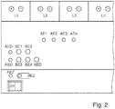
- Fig. 2:
- prinziphaft einen Aktor eines solchen elektrischen/elektronischen Installationssystems mit vier Lastausgängen beziehungsweise Kanälen, in der Draufsicht.
- Fig. 1:
- in principle an electrical / electronic installation system comprising several actuators, as a block diagram;
- Fig. 2:
- in principle an actuator of such an electrical / electronic installation system with four load outputs or channels, in plan view.
Wie aus den Figuren hervorgeht, weist das für den Einsatz in Gebäuden vorgesehene elektrische/elektronische Installationssystem eine Vielzahl von jeweils als Reiheneinbaugerät ausgeführten Aktoren A1 bis An auf, welche über ein Bussystem BUS miteinander in Verbindung stehen. Jeder der Aktoren A1 bis An weist mehrere (vier) Lastausgänge L1 bis Ln beziehungsweise Kanäle auf, die zur Beeinflussung von angeschlossenen (zugeordneten) Lasten LA vorgesehen sind, wobei jedem Lastausgang L1 bis Ln ein Anzeigeelement AE1 bis AEn zugeordnet ist. Die Aktoren A1 bis An weisen jeweils mehrere erste Betätigungselemente BE1 bis BE4 auf, die zur bedarfsweisen, manuellen Beeinflussung der angeschlossenen (zugeordneten) Lasten LA vorgesehen sind. Es ist zumindest ein zweites Betätigungselement BEZ vorgesehen, welches zur Programmierung dient. Ausgelöst durch die Betätigung eines der ersten Betätigungselemente BE1 bis BE4 ist über die Logikeinheit L eines jeden Aktors A1 bis An jeweils zumindest ein Anzeigeelement AE1 bis AEn des betreffenden Aktors A1 bis An beeinflussbar. Zum Zweck der gleichzeitigen Beeinflussung von Anzeigeelementen AE1 bis AEn mehrerer Aktoren A1 bis An stehen die Logikeinheiten L der Aktoren A1 bis An datentechnisch über das Bussystem BUS miteinander in Verbindung, und weist die Logikeinheit L eines jeden Aktors A1 bis An je eine Betätigungselementeauswertestufe BS und je eine Anzeigeelementeaktivierungsstufe AS auf.As can be seen from the figures, the electrical / electronic installation system provided for use in buildings has a plurality of actuators A1 to An, each designed as a series installation device, which are connected to one another via a bus system BUS. Each of the actuators A1 to An has several (four) load outputs L1 to Ln or channels, which are provided for influencing connected (assigned) loads LA, a display element AE1 to AEn being assigned to each load output L1 to Ln. The actuators A1 to An each have a plurality of first actuating elements BE1 to BE4 which are provided for manual influencing of the connected (assigned) loads LA as required. At least one second actuating element BEZ is provided, which is used for programming. Triggered by the actuation of one of the first actuation elements BE1 to BE4, at least one display element AE1 to AEn of the relevant actuator A1 to An can be influenced via the logic unit L of each actuator A1 to An. For the purpose of simultaneously influencing display elements AE1 to AEn of several actuators A1 to An, the logic units L of the actuators A1 to An are connected to one another for data purposes via the bus system BUS, and the logic unit L of each actuator A1 to An has an actuating element evaluation stage BS and each a display element activation level AS.
Wie des Weiteren aus den Figuren hervorgeht, sind gemäß des vorliegenden Ausführungsbeispiels vier Betätigungselemente BE1 bis BE4 eines jeden Aktors A1 bis An zu einer Betätigungselementengruppe zusammengefasst. Vier Anzeigeelemente AE1 bis AEn sind bei jedem der Aktoren A1 bis An zu einer Anzeigeeinheit zusammengefasst. Die Anzeigeelement AE1 bis AEn sind jeweils als Leuchtdiode LED ausgeführt. Jeder Aktor A1 bis An weist vier Lastausgänge L1 bis Ln auf, wobei jedem Lastausgang L1 bis Ln ein als Leuchtdiode LED ausgeführtes Anzeigeelement AE1 bis AEn zugeordnet ist. Jeder Aktor A1 bis An weist zudem ein zweites Betätigungselement BEZ auf, welches zur Betätigung eines Programmierschalters vorgesehen ist. Diesem zweiten Betätigungselement BEZ ist ein als Programmier-LED ausgeführtes zweites Anzeigeelement AEZ zugeordnet. Jeder der Aktoren A1 bis An verfügt über eine erste Schnittstelle S1, über welche diese an ein Bussystem BUS angeschlossen sind. Beim vorliegenden Ausführungsbeispiel ist die erste Schnittstelle S1 dafür vorgesehen, die Aktoren A1 bis An an ein als KNX-Bussystem ausgeführtes Bussystem BUS zum Anschluss zu bringen. Die Logikeinheit L eines jeden Aktors A1 bis An weist einen Mikrocontroller MC auf.As can also be seen from the figures, according to the present exemplary embodiment, four actuation elements BE1 to BE4 of each actuator A1 to An are combined to form an actuation element group. Four display elements AE1 to AEn are combined into a display unit for each of the actuators A1 to An. The display elements AE1 to AEn are each designed as a light-emitting diode LED. Each actuator A1 to An has four load outputs L1 to Ln, a display element AE1 to AEn in the form of a light-emitting diode LED being assigned to each load output L1 to Ln. Each actuator A1 to An also has a second actuating element BEZ, which is used to actuate a Programming switch is provided. A second display element AEZ designed as a programming LED is assigned to this second actuating element BEZ. Each of the actuators A1 to An has a first interface S1 via which they are connected to a bus system BUS. In the present exemplary embodiment, the first interface S1 is provided for connecting actuators A1 to An to a bus system BUS designed as a KNX bus system. The logic unit L of each actuator A1 to An has a microcontroller MC.
Vorteilhafterweise ermöglicht ein derart ausgestaltetes elektrisches/elektronisches Installationssystem dem Anwender/Installateur auf besonders schnelle und einfache Art und Weise, sich einen Überblick über den Status der Lastausgänge L1 bis Ln eines jeden einzelnen Aktors A1 bis An zu verschaffen. Vorteilhafterweise geschieht dies für alle Aktoren A1 bis An besonders schnell durch die Betätigung eines einzigen ersten Betätiungselementes BE1 bis BE4 an einem beliebigen Aktor A1 bis An.Advantageously, an electrical / electronic installation system configured in this way enables the user / installer to obtain an overview of the status of the load outputs L1 to Ln of each individual actuator A1 to An in a particularly fast and simple manner. Advantageously, this is done particularly quickly for all actuators A1 to An by actuating a single first actuating element BE1 to BE4 on any actuator A1 to An.
Beispielsweise wird durch ein kurzzeitiges Betätigen des ersten Bedienelementes BE1 am Aktor A1 über die Betätigungselementeauswertestufe BS und den Microcontroller MC der Logikeinheit L ein Anzeigemodus aktiviert. Die Anzeigeelemente AE1 bis AEn werden über die Anzeigeelementeaktivierungsstufe AS angesteuert und zeigen dadurch den aktuellen Status der Lastausgänge L1 bis Ln des Aktors A1 an. Gleichzeitig wird über den Microcontroller MC der Logikeinheit L des Aktors A1 ein Steuersignal erzeugt, welches über die erste Schnittstelle S1 in das Bussystem BUS abgegeben wird. Über das Bussystem BUS empfangen die weiteren Aktoren A2 bis An dieses Steuersignal, wodurch bei diesen Aktoren A2 bis An gleichzeitig der Anzeigemodus aktiviert wird und daraufhin über ihre Anzeigeelementeaktivierungsstufe AS jeweils auch ihre Anzeigeelemente AE1 bis AEn angesteuert werden, um den aktuellen Status ihrer Lastausgänge L1 bis Ln anzuzeigen. Bei einer entsprechenden Einstellung der Logikeinheit L der Aktoren A1 bis An besteht zudem die Möglichkeit, mit dem Aktivieren des Anzeigemodus einen Handbedienmodus zu aktivieren, um die angeschlossenen beziehungsweise zugehörigen Lasten LA manuell beeinflussen zu können.For example, by briefly actuating the first operating element BE1 on the actuator A1 via the actuating element evaluation stage BS and the microcontroller MC of the logic unit L, a display mode is activated. The display elements AE1 to AEn are controlled via the display element activation stage AS and thereby display the current status of the load outputs L1 to Ln of the actuator A1. At the same time, a control signal is generated via the microcontroller MC of the logic unit L of the actuator A1, which is output via the first interface S1 into the bus system BUS. The other actuators A2 to An receive this control signal via the bus system BUS, whereby the display mode is activated at the same time for these actuators A2 to An and their display elements AE1 to AEn are then controlled via their display element activation stage AS in order to check the current status of their load outputs L1 to Ln display. With a corresponding setting of the logic unit L of the actuators A1 to An, there is also the possibility of activating a manual operating mode by activating the display mode in order to be able to manually influence the connected or associated loads LA.
Nach einer einstellbaren Zeit von zum Beispiel einer Minute wechseln die Aktoren A1 bis An aus ihrem Anzeigemodus wieder in ihren Standby-Modus und schalten über ihre Anzeigeelementeaktivierungsstufe AS ihre Anzeigeelemente AE1 bis AEn wieder aus, um Energie zu sparen.After an adjustable time of one minute, for example, the actuators A1 to An switch from their display mode back to their standby mode and switch their display elements AE1 to AEn off again via their display element activation stage AS in order to save energy.
Eine solche datentechnische Verknüpfung der Aktoren A1 bis An ermöglicht vorteilhafterweise somit das gleichzeitige Anzeigen der Statis aller Lastausgänge L1 bis Ln aller Aktoren A1 bis An über nur einen einzigen Tastendruck eines ersten Betätigungselementes BE1 bis BE4 (beispielsweise des ersten Betätigungselementes BE1) an einem beliebigen Aktor A1 bis An.Such a data link between the actuators A1 to An advantageously enables the simultaneous display of the status of all load outputs L1 to Ln of all actuators A1 to An by pressing a single button on a first actuating element BE1 to BE4 (for example the first actuating element BE1) on any actuator A1 until.
Es besteht zudem die Möglichkeit, zum Beispiel über eine einzige langzeitige Betätigung des ersten Bedienelementes BE1 am Aktor A1 eine dauerhafte Aktivierung des Anzeigemodus und damit auch eine Aktivierung der Anzeigeelemente AE1 bis AEn aller Aktoren A1 bis An vorzunehmen. Eine solche dauerhafte Aktivierung des Anzeigemodus kann dann zum Beispiel über eine einzige weitere langzeitige Betätigung des ersten Bedienelementes BE1 am Aktor A1 wieder außer Kraft genommen werden. Beispielsweise kann jedoch auch vorgesehen sein, dass über eine einzige langzeitige Betätigung des ersten Bedienelementes BE2 am Aktor A1 die Aktivierung des Anzeigemodus wieder außer Kraft genommen wird und alle Aktoren A1 bis An wieder in ihren Standby-Modus schalten. Um Energie zu sparen, sind dann alle Anzeigeelemente AE1 bis AEn aller Aktoren A1 bis An wieder ausgeschaltet. Bei einer entsprechenden Einstellung der Logikeinheit L der Aktoren A1 bis An besteht zudem die Möglichkeit, mit dem Aktivieren des Anzeigemodus zudem einen Handbedienmodus zu aktivieren, um die angeschlossenen beziehungsweise zugehörigen Lasten LA manuell beeinflussen zu können.There is also the possibility of permanently activating the display mode and thus also activating the display elements AE1 to AEn of all actuators A1 to An by a single long-term actuation of the first operating element BE1 on the actuator A1. Such a permanent activation of the display mode can then be deactivated again, for example, by a single further long-term actuation of the first operating element BE1 on the actuator A1. For example, however, provision can also be made for the activation of the display mode to be deactivated again via a single long-term actuation of the first operating element BE2 on actuator A1 and for all actuators A1 to An to switch back to their standby mode. In order to save energy, all display elements AE1 to AEn of all actuators A1 to An are then switched off again. With a corresponding setting of the logic unit L of the actuators A1 to An, there is also the option of activating a manual control mode by activating the display mode in order to be able to manually influence the connected or associated loads LA.
Die Erfindung ist anhand eines Ausführungsbeispiels beschrieben worden. Ohne den Umfang der geltenden Ansprüche zu verlassen, ergeben sich für einen Fachmann zahlreiche weitere Möglichkeiten, diese umzusetzen, ohne dass dieses im Rahmen dieser Ausführungen im Einzelnen näher erläutert werden müssen.The invention has been described using an exemplary embodiment. Without departing from the scope of the applicable claims, there are numerous other possibilities for a person skilled in the art to implement them without this having to be explained in more detail in the context of these explanations.
- A1 bis AnA1 to An
- AktorenActuators
- AE1 bis AEnAE1 to AEn
- AnzeigeelementeDisplay elements
- AEDAED
- Dritte AnzeigeelementeThird display elements
- AEZAEZ
- Zweites AnzeigeelementSecond display element
- ASAS
- AnzeigeelementeaktivierungsstufeIndicator activation level
- BE1 bis BE4BE1 to BE4
- Erste BetätigungselementeFirst actuators
- BEZBEZ
- Zweites BetätigungselementSecond actuator
- BSBS
- BetätigungselementeauswertestufeActuating element evaluation level
- BUSBUS
- BussystemBus system
- LL.
- LogikeinheitLogic unit
- LALA
- LastenLoads
- LEDLED
- Leuchtdiodelight emitting diode
- L1 bis LnL1 to Ln
- LastausgängeLoad outputs
- MCMC
- MikrocontrollerMicrocontroller
- S1S1
- Erste SchnittstelleFirst interface
Claims (12)
Applications Claiming Priority (1)
| Application Number | Priority Date | Filing Date | Title |
|---|---|---|---|
| DE102019110652.4A DE102019110652B4 (en) | 2019-04-25 | 2019-04-25 | Electrical / electronic installation system |
Publications (3)
| Publication Number | Publication Date |
|---|---|
| EP3731039A2 true EP3731039A2 (en) | 2020-10-28 |
| EP3731039A3 EP3731039A3 (en) | 2020-11-04 |
| EP3731039B1 EP3731039B1 (en) | 2021-09-22 |
Family
ID=69593617
Family Applications (1)
| Application Number | Title | Priority Date | Filing Date |
|---|---|---|---|
| EP20157370.6A Active EP3731039B1 (en) | 2019-04-25 | 2020-02-14 | Electric/electronic installation system |
Country Status (2)
| Country | Link |
|---|---|
| EP (1) | EP3731039B1 (en) |
| DE (1) | DE102019110652B4 (en) |
Citations (1)
| Publication number | Priority date | Publication date | Assignee | Title |
|---|---|---|---|---|
| DE102012107216B4 (en) | 2012-08-07 | 2017-07-27 | Insta Gmbh | Electric / electronic actuator |
Family Cites Families (4)
| Publication number | Priority date | Publication date | Assignee | Title |
|---|---|---|---|---|
| DE20321235U1 (en) * | 2003-07-10 | 2006-06-14 | Insta Elektro Gmbh | Actuator, especially for building automation applications, has separate groups of control keys and indicators, for showing the state of functional units connected to individual actuator channels |
| US10289079B2 (en) * | 2011-09-30 | 2019-05-14 | Siemens Schweiz Ag | Management system using function abstraction for output generation |
| DE102014220059A1 (en) * | 2014-10-02 | 2016-04-07 | HiAsset GmbH | Control for building lighting and other building services installations |
| DE202016106008U1 (en) * | 2016-10-26 | 2016-11-23 | Insta Elektro Gmbh | Electric / electronic control unit |
-
2019
- 2019-04-25 DE DE102019110652.4A patent/DE102019110652B4/en not_active Withdrawn - After Issue
-
2020
- 2020-02-14 EP EP20157370.6A patent/EP3731039B1/en active Active
Patent Citations (1)
| Publication number | Priority date | Publication date | Assignee | Title |
|---|---|---|---|---|
| DE102012107216B4 (en) | 2012-08-07 | 2017-07-27 | Insta Gmbh | Electric / electronic actuator |
Also Published As
| Publication number | Publication date |
|---|---|
| DE102019110652A1 (en) | 2020-10-29 |
| EP3731039B1 (en) | 2021-09-22 |
| EP3731039A3 (en) | 2020-11-04 |
| DE102019110652B4 (en) | 2021-09-09 |
Similar Documents
| Publication | Publication Date | Title |
|---|---|---|
| WO1999048251A1 (en) | Method for commissioning a bus system and corresponding bus system | |
| DE102008001942B3 (en) | Mobile heating system | |
| EP0898442A1 (en) | Process and circuit for initialising and monitoring at least one electrical load | |
| DE202010007203U1 (en) | Electric distribution for the supply of lamp groups | |
| EP3251469B1 (en) | Method for operating devices in a lighting system | |
| DE102016120081A1 (en) | Method for commissioning and / or maintenance of a fire alarm and / or extinguishing control panel and device therefor | |
| DE102008057976A1 (en) | Lighting system with emergency lighting | |
| DE102012107216B4 (en) | Electric / electronic actuator | |
| EP3731039B1 (en) | Electric/electronic installation system | |
| DE102012210959A1 (en) | Distributed consumer control system and system commissioning process | |
| DE102011056114B3 (en) | Building installation system for supplying power to bus devices e.g. lamp, has bus subscribers that are equipped with power conversion unit, energy storage unit and energy feeding unit | |
| DE102019110653B4 (en) | Electrical / electronic installation system | |
| DE102006016080A1 (en) | Power supply device for a plurality of consumers to be connected thereto | |
| EP1993010A2 (en) | Sensor unit | |
| EP2001270B1 (en) | Multichannel built-in dimmer | |
| DE19960870A1 (en) | Electrical or electronic switch device for connecting switch appliance with adjustable parameters, includes memory store holding main settings for switch appliance assigned to it while supplying resistance | |
| DE102019001351A1 (en) | SHUT-OFF DEVICE AND PHOTOVOLTAIC ARRANGEMENT | |
| DE202016106008U1 (en) | Electric / electronic control unit | |
| EP2775080B1 (en) | Control device for a drive of a window or the like | |
| DE102015115116B4 (en) | Modular installation device and method for operating such an installation device | |
| EP2116108B1 (en) | Electronic ballast for a lamp | |
| EP2097958A1 (en) | Gas-insulated switchgear assembly | |
| EP2582211B1 (en) | Dali distribution device | |
| DE102021001940A1 (en) | Temperature control device, system with temperature control device and method for changing an operating state of an electronic component | |
| DE102007005995A1 (en) | Operating unit for lighting component operated over digital addressable lighting interface bus, comprises control module, which has input plug connection for contacting low voltage plug connection of power supply module |
Legal Events
| Date | Code | Title | Description |
|---|---|---|---|
| PUAI | Public reference made under article 153(3) epc to a published international application that has entered the european phase |
Free format text: ORIGINAL CODE: 0009012 |
|
| STAA | Information on the status of an ep patent application or granted ep patent |
Free format text: STATUS: THE APPLICATION HAS BEEN PUBLISHED |
|
| PUAL | Search report despatched |
Free format text: ORIGINAL CODE: 0009013 |
|
| AK | Designated contracting states |
Kind code of ref document: A2 Designated state(s): AL AT BE BG CH CY CZ DE DK EE ES FI FR GB GR HR HU IE IS IT LI LT LU LV MC MK MT NL NO PL PT RO RS SE SI SK SM TR |
|
| AX | Request for extension of the european patent |
Extension state: BA ME |
|
| AK | Designated contracting states |
Kind code of ref document: A3 Designated state(s): AL AT BE BG CH CY CZ DE DK EE ES FI FR GB GR HR HU IE IS IT LI LT LU LV MC MK MT NL NO PL PT RO RS SE SI SK SM TR |
|
| AX | Request for extension of the european patent |
Extension state: BA ME |
|
| RIC1 | Information provided on ipc code assigned before grant |
Ipc: G05B 19/10 20060101ALI20200928BHEP Ipc: G05B 19/042 20060101ALI20200928BHEP Ipc: G05B 15/02 20060101AFI20200928BHEP |
|
| STAA | Information on the status of an ep patent application or granted ep patent |
Free format text: STATUS: REQUEST FOR EXAMINATION WAS MADE |
|
| 17P | Request for examination filed |
Effective date: 20201117 |
|
| RBV | Designated contracting states (corrected) |
Designated state(s): AL AT BE BG CH CY CZ DE DK EE ES FI FR GB GR HR HU IE IS IT LI LT LU LV MC MK MT NL NO PL PT RO RS SE SI SK SM TR |
|
| GRAP | Despatch of communication of intention to grant a patent |
Free format text: ORIGINAL CODE: EPIDOSNIGR1 |
|
| STAA | Information on the status of an ep patent application or granted ep patent |
Free format text: STATUS: GRANT OF PATENT IS INTENDED |
|
| INTG | Intention to grant announced |
Effective date: 20210713 |
|
| GRAS | Grant fee paid |
Free format text: ORIGINAL CODE: EPIDOSNIGR3 |
|
| GRAA | (expected) grant |
Free format text: ORIGINAL CODE: 0009210 |
|
| STAA | Information on the status of an ep patent application or granted ep patent |
Free format text: STATUS: THE PATENT HAS BEEN GRANTED |
|
| AK | Designated contracting states |
Kind code of ref document: B1 Designated state(s): AL AT BE BG CH CY CZ DE DK EE ES FI FR GB GR HR HU IE IS IT LI LT LU LV MC MK MT NL NO PL PT RO RS SE SI SK SM TR |
|
| REG | Reference to a national code |
Ref country code: GB Ref legal event code: FG4D Free format text: NOT ENGLISH |
|
| REG | Reference to a national code |
Ref country code: DE Ref legal event code: R096 Ref document number: 502020000198 Country of ref document: DE |
|
| REG | Reference to a national code |
Ref country code: IE Ref legal event code: FG4D Free format text: LANGUAGE OF EP DOCUMENT: GERMAN |
|
| REG | Reference to a national code |
Ref country code: CH Ref legal event code: EP Ref country code: AT Ref legal event code: REF Ref document number: 1432801 Country of ref document: AT Kind code of ref document: T Effective date: 20211015 |
|
| REG | Reference to a national code |
Ref country code: SE Ref legal event code: TRGR |
|
| REG | Reference to a national code |
Ref country code: NL Ref legal event code: FP |
|
| REG | Reference to a national code |
Ref country code: LT Ref legal event code: MG9D |
|
| PG25 | Lapsed in a contracting state [announced via postgrant information from national office to epo] |
Ref country code: RS Free format text: LAPSE BECAUSE OF FAILURE TO SUBMIT A TRANSLATION OF THE DESCRIPTION OR TO PAY THE FEE WITHIN THE PRESCRIBED TIME-LIMIT Effective date: 20210922 Ref country code: HR Free format text: LAPSE BECAUSE OF FAILURE TO SUBMIT A TRANSLATION OF THE DESCRIPTION OR TO PAY THE FEE WITHIN THE PRESCRIBED TIME-LIMIT Effective date: 20210922 Ref country code: FI Free format text: LAPSE BECAUSE OF FAILURE TO SUBMIT A TRANSLATION OF THE DESCRIPTION OR TO PAY THE FEE WITHIN THE PRESCRIBED TIME-LIMIT Effective date: 20210922 Ref country code: NO Free format text: LAPSE BECAUSE OF FAILURE TO SUBMIT A TRANSLATION OF THE DESCRIPTION OR TO PAY THE FEE WITHIN THE PRESCRIBED TIME-LIMIT Effective date: 20211222 Ref country code: LT Free format text: LAPSE BECAUSE OF FAILURE TO SUBMIT A TRANSLATION OF THE DESCRIPTION OR TO PAY THE FEE WITHIN THE PRESCRIBED TIME-LIMIT Effective date: 20210922 Ref country code: BG Free format text: LAPSE BECAUSE OF FAILURE TO SUBMIT A TRANSLATION OF THE DESCRIPTION OR TO PAY THE FEE WITHIN THE PRESCRIBED TIME-LIMIT Effective date: 20211222 |
|
| PG25 | Lapsed in a contracting state [announced via postgrant information from national office to epo] |
Ref country code: LV Free format text: LAPSE BECAUSE OF FAILURE TO SUBMIT A TRANSLATION OF THE DESCRIPTION OR TO PAY THE FEE WITHIN THE PRESCRIBED TIME-LIMIT Effective date: 20210922 Ref country code: GR Free format text: LAPSE BECAUSE OF FAILURE TO SUBMIT A TRANSLATION OF THE DESCRIPTION OR TO PAY THE FEE WITHIN THE PRESCRIBED TIME-LIMIT Effective date: 20211223 |
|
| PG25 | Lapsed in a contracting state [announced via postgrant information from national office to epo] |
Ref country code: IS Free format text: LAPSE BECAUSE OF FAILURE TO SUBMIT A TRANSLATION OF THE DESCRIPTION OR TO PAY THE FEE WITHIN THE PRESCRIBED TIME-LIMIT Effective date: 20220122 Ref country code: SK Free format text: LAPSE BECAUSE OF FAILURE TO SUBMIT A TRANSLATION OF THE DESCRIPTION OR TO PAY THE FEE WITHIN THE PRESCRIBED TIME-LIMIT Effective date: 20210922 Ref country code: RO Free format text: LAPSE BECAUSE OF FAILURE TO SUBMIT A TRANSLATION OF THE DESCRIPTION OR TO PAY THE FEE WITHIN THE PRESCRIBED TIME-LIMIT Effective date: 20210922 Ref country code: PT Free format text: LAPSE BECAUSE OF FAILURE TO SUBMIT A TRANSLATION OF THE DESCRIPTION OR TO PAY THE FEE WITHIN THE PRESCRIBED TIME-LIMIT Effective date: 20220124 Ref country code: PL Free format text: LAPSE BECAUSE OF FAILURE TO SUBMIT A TRANSLATION OF THE DESCRIPTION OR TO PAY THE FEE WITHIN THE PRESCRIBED TIME-LIMIT Effective date: 20210922 Ref country code: ES Free format text: LAPSE BECAUSE OF FAILURE TO SUBMIT A TRANSLATION OF THE DESCRIPTION OR TO PAY THE FEE WITHIN THE PRESCRIBED TIME-LIMIT Effective date: 20210922 Ref country code: EE Free format text: LAPSE BECAUSE OF FAILURE TO SUBMIT A TRANSLATION OF THE DESCRIPTION OR TO PAY THE FEE WITHIN THE PRESCRIBED TIME-LIMIT Effective date: 20210922 Ref country code: CZ Free format text: LAPSE BECAUSE OF FAILURE TO SUBMIT A TRANSLATION OF THE DESCRIPTION OR TO PAY THE FEE WITHIN THE PRESCRIBED TIME-LIMIT Effective date: 20210922 Ref country code: AL Free format text: LAPSE BECAUSE OF FAILURE TO SUBMIT A TRANSLATION OF THE DESCRIPTION OR TO PAY THE FEE WITHIN THE PRESCRIBED TIME-LIMIT Effective date: 20210922 |
|
| REG | Reference to a national code |
Ref country code: DE Ref legal event code: R097 Ref document number: 502020000198 Country of ref document: DE |
|
| PG25 | Lapsed in a contracting state [announced via postgrant information from national office to epo] |
Ref country code: DK Free format text: LAPSE BECAUSE OF FAILURE TO SUBMIT A TRANSLATION OF THE DESCRIPTION OR TO PAY THE FEE WITHIN THE PRESCRIBED TIME-LIMIT Effective date: 20210922 |
|
| PLBE | No opposition filed within time limit |
Free format text: ORIGINAL CODE: 0009261 |
|
| STAA | Information on the status of an ep patent application or granted ep patent |
Free format text: STATUS: NO OPPOSITION FILED WITHIN TIME LIMIT |
|
| 26N | No opposition filed |
Effective date: 20220623 |
|
| PG25 | Lapsed in a contracting state [announced via postgrant information from national office to epo] |
Ref country code: MC Free format text: LAPSE BECAUSE OF FAILURE TO SUBMIT A TRANSLATION OF THE DESCRIPTION OR TO PAY THE FEE WITHIN THE PRESCRIBED TIME-LIMIT Effective date: 20210922 |
|
| REG | Reference to a national code |
Ref country code: BE Ref legal event code: MM Effective date: 20220228 |
|
| PG25 | Lapsed in a contracting state [announced via postgrant information from national office to epo] |
Ref country code: LU Free format text: LAPSE BECAUSE OF NON-PAYMENT OF DUE FEES Effective date: 20220214 |
|
| PG25 | Lapsed in a contracting state [announced via postgrant information from national office to epo] |
Ref country code: SI Free format text: LAPSE BECAUSE OF FAILURE TO SUBMIT A TRANSLATION OF THE DESCRIPTION OR TO PAY THE FEE WITHIN THE PRESCRIBED TIME-LIMIT Effective date: 20210922 |
|
| PG25 | Lapsed in a contracting state [announced via postgrant information from national office to epo] |
Ref country code: IE Free format text: LAPSE BECAUSE OF NON-PAYMENT OF DUE FEES Effective date: 20220214 |
|
| PG25 | Lapsed in a contracting state [announced via postgrant information from national office to epo] |
Ref country code: BE Free format text: LAPSE BECAUSE OF NON-PAYMENT OF DUE FEES Effective date: 20220228 |
|
| PGFP | Annual fee paid to national office [announced via postgrant information from national office to epo] |
Ref country code: NL Payment date: 20230223 Year of fee payment: 4 |
|
| PGFP | Annual fee paid to national office [announced via postgrant information from national office to epo] |
Ref country code: FR Payment date: 20230118 Year of fee payment: 4 |
|
| PGFP | Annual fee paid to national office [announced via postgrant information from national office to epo] |
Ref country code: SE Payment date: 20230206 Year of fee payment: 4 Ref country code: IT Payment date: 20230228 Year of fee payment: 4 Ref country code: DE Payment date: 20230105 Year of fee payment: 4 |
|
| REG | Reference to a national code |
Ref country code: CH Ref legal event code: PL |
|
| PG25 | Lapsed in a contracting state [announced via postgrant information from national office to epo] |
Ref country code: LI Free format text: LAPSE BECAUSE OF NON-PAYMENT OF DUE FEES Effective date: 20230228 Ref country code: CH Free format text: LAPSE BECAUSE OF NON-PAYMENT OF DUE FEES Effective date: 20230228 |
|
| PGFP | Annual fee paid to national office [announced via postgrant information from national office to epo] |
Ref country code: NL Payment date: 20240219 Year of fee payment: 5 |