EP3730957A1 - Charge capacity calculation device and method for energy storage system - Google Patents
Charge capacity calculation device and method for energy storage system Download PDFInfo
- Publication number
- EP3730957A1 EP3730957A1 EP19756861.1A EP19756861A EP3730957A1 EP 3730957 A1 EP3730957 A1 EP 3730957A1 EP 19756861 A EP19756861 A EP 19756861A EP 3730957 A1 EP3730957 A1 EP 3730957A1
- Authority
- EP
- European Patent Office
- Prior art keywords
- energy storage
- storage system
- voltage
- current
- state variable
- Prior art date
- Legal status (The legal status is an assumption and is not a legal conclusion. Google has not performed a legal analysis and makes no representation as to the accuracy of the status listed.)
- Granted
Links
Images





Classifications
-
- G—PHYSICS
- G01—MEASURING; TESTING
- G01R—MEASURING ELECTRIC VARIABLES; MEASURING MAGNETIC VARIABLES
- G01R31/00—Arrangements for testing electric properties; Arrangements for locating electric faults; Arrangements for electrical testing characterised by what is being tested not provided for elsewhere
- G01R31/36—Arrangements for testing, measuring or monitoring the electrical condition of accumulators or electric batteries, e.g. capacity or state of charge [SoC]
- G01R31/367—Software therefor, e.g. for battery testing using modelling or look-up tables
-
- G—PHYSICS
- G01—MEASURING; TESTING
- G01R—MEASURING ELECTRIC VARIABLES; MEASURING MAGNETIC VARIABLES
- G01R31/00—Arrangements for testing electric properties; Arrangements for locating electric faults; Arrangements for electrical testing characterised by what is being tested not provided for elsewhere
- G01R31/36—Arrangements for testing, measuring or monitoring the electrical condition of accumulators or electric batteries, e.g. capacity or state of charge [SoC]
- G01R31/382—Arrangements for monitoring battery or accumulator variables, e.g. SoC
- G01R31/3842—Arrangements for monitoring battery or accumulator variables, e.g. SoC combining voltage and current measurements
-
- G—PHYSICS
- G01—MEASURING; TESTING
- G01R—MEASURING ELECTRIC VARIABLES; MEASURING MAGNETIC VARIABLES
- G01R31/00—Arrangements for testing electric properties; Arrangements for locating electric faults; Arrangements for electrical testing characterised by what is being tested not provided for elsewhere
- G01R31/36—Arrangements for testing, measuring or monitoring the electrical condition of accumulators or electric batteries, e.g. capacity or state of charge [SoC]
- G01R31/389—Measuring internal impedance, internal conductance or related variables
-
- H—ELECTRICITY
- H02—GENERATION; CONVERSION OR DISTRIBUTION OF ELECTRIC POWER
- H02J—ELECTRIC POWER NETWORKS; CIRCUIT ARRANGEMENTS OR SYSTEMS FOR SUPPLYING OR DISTRIBUTING ELECTRIC POWER; SYSTEMS FOR STORING ELECTRIC ENERGY
- H02J3/00—Circuit arrangements for AC mains or AC distribution networks
- H02J3/28—Arrangements for balancing of the load in networks by storage of energy
- H02J3/32—Arrangements for balancing of the load in networks by storage of energy using batteries or super capacitors with converting means
-
- G—PHYSICS
- G01—MEASURING; TESTING
- G01R—MEASURING ELECTRIC VARIABLES; MEASURING MAGNETIC VARIABLES
- G01R31/00—Arrangements for testing electric properties; Arrangements for locating electric faults; Arrangements for electrical testing characterised by what is being tested not provided for elsewhere
- G01R31/36—Arrangements for testing, measuring or monitoring the electrical condition of accumulators or electric batteries, e.g. capacity or state of charge [SoC]
- G01R31/3644—Constructional arrangements
- G01R31/3648—Constructional arrangements comprising digital calculation means, e.g. for performing an algorithm
-
- G—PHYSICS
- G01—MEASURING; TESTING
- G01R—MEASURING ELECTRIC VARIABLES; MEASURING MAGNETIC VARIABLES
- G01R31/00—Arrangements for testing electric properties; Arrangements for locating electric faults; Arrangements for electrical testing characterised by what is being tested not provided for elsewhere
- G01R31/36—Arrangements for testing, measuring or monitoring the electrical condition of accumulators or electric batteries, e.g. capacity or state of charge [SoC]
- G01R31/382—Arrangements for monitoring battery or accumulator variables, e.g. SoC
-
- G—PHYSICS
- G01—MEASURING; TESTING
- G01R—MEASURING ELECTRIC VARIABLES; MEASURING MAGNETIC VARIABLES
- G01R31/00—Arrangements for testing electric properties; Arrangements for locating electric faults; Arrangements for electrical testing characterised by what is being tested not provided for elsewhere
- G01R31/36—Arrangements for testing, measuring or monitoring the electrical condition of accumulators or electric batteries, e.g. capacity or state of charge [SoC]
- G01R31/382—Arrangements for monitoring battery or accumulator variables, e.g. SoC
- G01R31/3828—Arrangements for monitoring battery or accumulator variables, e.g. SoC using current integration
-
- G—PHYSICS
- G01—MEASURING; TESTING
- G01R—MEASURING ELECTRIC VARIABLES; MEASURING MAGNETIC VARIABLES
- G01R31/00—Arrangements for testing electric properties; Arrangements for locating electric faults; Arrangements for electrical testing characterised by what is being tested not provided for elsewhere
- G01R31/36—Arrangements for testing, measuring or monitoring the electrical condition of accumulators or electric batteries, e.g. capacity or state of charge [SoC]
- G01R31/385—Arrangements for measuring battery or accumulator variables
- G01R31/387—Determining ampere-hour charge capacity or SoC
-
- H—ELECTRICITY
- H02—GENERATION; CONVERSION OR DISTRIBUTION OF ELECTRIC POWER
- H02J—ELECTRIC POWER NETWORKS; CIRCUIT ARRANGEMENTS OR SYSTEMS FOR SUPPLYING OR DISTRIBUTING ELECTRIC POWER; SYSTEMS FOR STORING ELECTRIC ENERGY
- H02J7/00—Circuit arrangements for charging or discharging batteries or for supplying loads from batteries
- H02J7/80—Circuit arrangements for charging or discharging batteries or for supplying loads from batteries including monitoring or indicating arrangements
-
- Y—GENERAL TAGGING OF NEW TECHNOLOGICAL DEVELOPMENTS; GENERAL TAGGING OF CROSS-SECTIONAL TECHNOLOGIES SPANNING OVER SEVERAL SECTIONS OF THE IPC; TECHNICAL SUBJECTS COVERED BY FORMER USPC CROSS-REFERENCE ART COLLECTIONS [XRACs] AND DIGESTS
- Y02—TECHNOLOGIES OR APPLICATIONS FOR MITIGATION OR ADAPTATION AGAINST CLIMATE CHANGE
- Y02B—CLIMATE CHANGE MITIGATION TECHNOLOGIES RELATED TO BUILDINGS, e.g. HOUSING, HOUSE APPLIANCES OR RELATED END-USER APPLICATIONS
- Y02B70/00—Technologies for an efficient end-user side electric power management and consumption
- Y02B70/30—Systems integrating technologies related to power network operation and communication or information technologies for improving the carbon footprint of the management of residential or tertiary loads, i.e. smart grids as climate change mitigation technology in the buildings sector, including also the last stages of power distribution and the control, monitoring or operating management systems at local level
- Y02B70/3225—Demand response systems, e.g. load shedding, peak shaving
-
- Y—GENERAL TAGGING OF NEW TECHNOLOGICAL DEVELOPMENTS; GENERAL TAGGING OF CROSS-SECTIONAL TECHNOLOGIES SPANNING OVER SEVERAL SECTIONS OF THE IPC; TECHNICAL SUBJECTS COVERED BY FORMER USPC CROSS-REFERENCE ART COLLECTIONS [XRACs] AND DIGESTS
- Y02—TECHNOLOGIES OR APPLICATIONS FOR MITIGATION OR ADAPTATION AGAINST CLIMATE CHANGE
- Y02E—REDUCTION OF GREENHOUSE GAS [GHG] EMISSIONS, RELATED TO ENERGY GENERATION, TRANSMISSION OR DISTRIBUTION
- Y02E60/00—Enabling technologies; Technologies with a potential or indirect contribution to GHG emissions mitigation
- Y02E60/10—Energy storage using batteries
-
- Y—GENERAL TAGGING OF NEW TECHNOLOGICAL DEVELOPMENTS; GENERAL TAGGING OF CROSS-SECTIONAL TECHNOLOGIES SPANNING OVER SEVERAL SECTIONS OF THE IPC; TECHNICAL SUBJECTS COVERED BY FORMER USPC CROSS-REFERENCE ART COLLECTIONS [XRACs] AND DIGESTS
- Y04—INFORMATION OR COMMUNICATION TECHNOLOGIES HAVING AN IMPACT ON OTHER TECHNOLOGY AREAS
- Y04S—SYSTEMS INTEGRATING TECHNOLOGIES RELATED TO POWER NETWORK OPERATION, COMMUNICATION OR INFORMATION TECHNOLOGIES FOR IMPROVING THE ELECTRICAL POWER GENERATION, TRANSMISSION, DISTRIBUTION, MANAGEMENT OR USAGE, i.e. SMART GRIDS
- Y04S20/00—Management or operation of end-user stationary applications or the last stages of power distribution; Controlling, monitoring or operating thereof
- Y04S20/20—End-user application control systems
- Y04S20/222—Demand response systems, e.g. load shedding, peak shaving
Definitions
- the present invention relates to an apparatus and a method for calculating the charging capacity of an energy storage system.
- the present invention relates to a device and method for accurately calculating a charging capacity of an energy storage system by increasing the accuracy of a voltage model used in an extended Kalman filter.
- a typical example of these technologies is an energy storage system in which the surplus electric power of the system is stored in the battery or the insufficient electric power of the system is supplied from the battery.
- the energy storage system In order to maintain the life of the energy storage system for a long time and to use it safely, the energy storage system must be operated within the proper charging capacity range, and the life time of the energy storage system greatly changes according to the number of charging/discharging cycles.
- a conventional method of calculating the charging capacity (SOC) of an energy storage system was a current integration method.
- the conventional current integration method there is an error in the current sensor for measuring the current, and in the course of integrating the current, the error of the current sensor is also accumulated, so that it is difficult to calculate the accurate charging capacity.
- the present invention proposes a device and method for reducing the charging capacity error of an energy storage system by accurately calculating the resistance (R) and capacitance (C) used to calculate the voltage model of the energy storage system and performing final calculation using the Kalman filter having a high specific weight of the voltage model.
- the present invention provides a device and method for accurately calculating a charging capacity of an energy storage system by accurately calculating a voltage model of an energy storage system.
- the present invention provides a device and method for accurately calculating a charging capacity by accurately calculating a resistance (R) and a capacitance (C) used in a voltage model of an energy storage system and substituting an accurate voltage model into an extended Kalman filter.
- Embodiments of the present invention provide a method of calculating a resistance (R) and a capacitance (C) of an energy storage system.
- the method includes: a current application step of applying a predetermined current having a constant value to the energy storage system; a first voltage measurement step of measuring a voltage of the energy storage system while a predetermined current having a constant value is applied to the energy storage system; a second voltage measurement step of measuring a voltage of the energy storage system after breaking a predetermined current having a constant value applied to the energy storage system; and a resistance (R) and capacitance (C) calculation step of calculating a resistance (R) and a capacitance (C) of the energy storage system based on the voltage of the energy storage system measured in the first voltage measurement step, the voltage of the energy storage system measured in the second voltage measurement step, and the predetermined current having the constant value.
- the predetermined current having a constant value applied in the current application step may be a current between a minimum current value and a 2c-rate, which is capable of measuring a resistance and a capacitance value of the energy storage system.
- the predetermined current having a constant value applied in the current application step may be a current between a minimum current value and a 0.1c-rate, which is capable of measuring a resistance and a capacitance value of the energy storage system.
- the method may further include: a state variable calculation step of calculating a state variable of the extended Kalman filter using the resistance and the capacitance of the energy storage system; and an energy storage system charging capacity calculation step of substituting the state variable into the extended Kalman filter to calculate a charging capacity of the energy storage system.
- the extended Kalman filter may repeatedly perform: time-updating the state variable; time-updating the error covariance of the state variable; calculating a Kalman gain of the extended Kalman filter; estimating a state variable using the gain; and correcting the error covariance of the state variable using the gain.
- the state variable calculation step may include: a charging capacity state variable calculation step of generating a state variable for the charging capacity of the energy storage system; and a voltage state variable calculation step of generating a state variable for the voltage of the energy storage system.
- the charging capacity state variable calculation step may calculate a charging capacity state variable using a current integration method of integrating the current measured in the energy storage system, wherein the calculated charging capacity state variable may be time-updated according to Equation 1 below.
- SOC k + 1 SOC k ⁇ i k ⁇ t Q capacity
- the voltage state variable calculation step may calculate a voltage state variable of the energy storage system using a voltage model circuit, wherein the calculated voltage state variable may be time-updated according to Equation 2 below.
- V 1 k + 1 exp ⁇ ⁇ t R 1 C 1 V 1 k + R 1 1 ⁇ exp ⁇ ⁇ t R 1 C 1 I k (wherein R1 and C1 are resistance and capacitance values included in the circuit model of FIG. 5 , k: time index, I[k]: current measured at time index k, t: time)
- the voltage model circuit may include: an open voltage source for outputting a predetermined voltage according to a current value flowing through the energy storage system; one or more resistors; and one or more capacitors.
- an energy storage system includes: a plurality of battery racks; and a battery section controller (BSC) for controlling the plurality of battery racks, wherein the BSC includes: a voltage measurement unit for measuring the output voltage of the energy storage system; a current measurement unit for measuring the output current of the energy storage system; a storage unit in which a resistance (R) and a capacitance (C) look-up table of a temperature-dependent energy storage system calculated with a predetermined current having a constant value are stored; and a charging capacity calculation unit for calculating a charging capacity of the energy storage system based on the lookup table.
- the BSC includes: a voltage measurement unit for measuring the output voltage of the energy storage system; a current measurement unit for measuring the output current of the energy storage system; a storage unit in which a resistance (R) and a capacitance (C) look-up table of a temperature-dependent energy storage system calculated with a predetermined current having a constant value are stored; and a charging capacity calculation unit for calculating a charging capacity of the
- the voltage measurement unit may measure: a first voltage that is a voltage of the energy storage system while a predetermined current is applied to the energy storage system; and a second voltage that is a voltage of the energy storage system after the current applied to the energy storage system is cut off.
- the charging capacity calculation unit may include: a voltage state variable calculation unit for calculating a state variable for a voltage of the energy storage system based on a resistance and a capacitance of the lookup table; and a charging capacity state variable calculation unit for calculating a state variable for a charging capacity of the energy storage system using a current integration method for integrating the measured output current, wherein the calculated voltage state variable and the charging capacity state variable may be substituted into the Kalman filter to calculate the charging capacity of the energy storage system.
- the present invention may accurately calculate the voltage model of the energy storage system by accurately calculating the resistance (R) and the capacitance (C) used in the voltage model of the energy storage system.
- the present invention may accurately calculate the charging capacity of the energy storage system by calculating the accurate voltage model of the energy storage system.
- the charging capacity of an energy storage system was calculated using a current integration method as a method of calculating the charging capacity of a conventional energy storage system.
- the current integration method determines the charging capacity by integrating the charging current and the discharging current with time.
- there is an error in the current sensor for measuring the charging current and the discharging current there is an error in the current sensor for measuring the charging current and the discharging current. Such error accumulates as the time for integrating the current accumulates, so that the accuracy of the charging capacity finally calculated by the current accumulation method is lowered.
- the present invention proposes a method of accurately calculating the resistance (R) and the capacitance (C) used to calculate the voltage model of the energy storage system.
- FIG. 1 is a method of calculating a resistance (R) and a capacitance (C) used to calculate a voltage model of the energy storage system of the present invention.
- the present invention uses the resistance (R) and the capacitance (C) of the energy storage system to calculate the voltage model of the energy storage system.
- the method of calculating the resistance (R) and capacitance (C) of the energy storage system of the present invention is characterized by using a low c-rate current.
- the method of calculating the resistance (R) and the capacitance (C) of the energy storage system may be calculated using the DCPR method as shown in FIG. 3 .
- the present invention applies a predetermined current having a constant value to an energy storage system, measures the voltage change of the energy storage system, and based on this, calculates the resistance (R) and the capacitance (C) of the energy storage system.
- the current application step is a step of applying a predetermined current having a constant value to an energy storage system charged to a predetermined charging capacity. After applying a predetermined current having a constant value to the energy storage system in such a way, the first voltage measurement step is performed. At this time, the predetermined current having the constant value to be applied is a current having a low c-rate.
- the c-rate may mean the intensity of the current.
- the current having the constant value applied uses a current having a total of 2 to 3 c-rate or more.
- the inventor of the present invention invented that the resistance and the capacitance value of the energy storage system may be more accurately calculated by applying a c-rate current lower than 2 to 3c-rate.
- the low c-rate current may be a current having a value between a minimum current value and a 2c-rate value capable of measuring the resistance and capacitance of the energy storage system.
- the current having the low c-rate may be a current of 0.1 c-rate, which corresponds to 1/10 of the current of 1 c-rate.
- the voltage of the energy storage system changes after the application of the current.
- the voltage of the energy storage system may be stabilized quickly, and the more accurate resistance (R) and capacitance (C) of an energy storage system may be calculated.
- the first voltage measurement step of the present invention is a step of measuring a voltage of the energy storage system while a predetermined current having a constant value flows through the energy storage system.
- the voltage of the energy storage system varies by a predetermined value.
- the voltage of the energy storage system measured at this time is used in the step of calculating the resistance (R) and the capacitance (C), which will be described later.
- the second voltage measurement step of the present invention is a step of terminating the application of a predetermined current having a constant value after the first voltage measurement step and measuring the voltage of the energy storage system.
- the voltage of the energy storage system changes. For example, when current is applied in the charging direction and current is cut off, the voltage of the energy storage system may drop, and when a current is applied in the discharging direction and the current is cut off, the voltage of the energy storage system may rise.
- the voltage change of the energy storage system measured at this time is used in the step of calculating the resistance (R) and the capacitance (C), which will be described later.
- the resistance (R) and capacitance (C) calculation step is a step of calculating the resistance (R) and capacitance (C) of the energy storage system based on the voltage of the energy storage system measured in the first voltage measurement step, the voltage of the energy storage system measured in the second voltage measurement step, and the predetermined current having a constant value. Specifically, since a predetermined current having a constant value applied to the energy storage system is known and a voltage corresponding to the flow of a predetermined current having the constant value is known, the resistance (R) and the capacitance (C) of the energy storage system may be calculated.
- the Vcell is a sum of an OCV voltage, a voltage applied to R0, and a voltage applied to C1.
- the OCV value is a value preset according to the charging capacity of the battery cell.
- the resistance value of R0 is a value obtained by dividing the difference between the Vcell voltage Vt measured at time t and the Vcell voltage Vt+1 measured at time t+1 by the low c-rate current flowing in the circuit.
- the voltage applied to R0 is also known. Therefore, since the voltage value and the current value applied to C1 are known, the R1 value and the C1 value may be calculated.
- the resistance (R) and the capacitance (C) of the energy storage system which are repeatedly calculated while changing the temperature of the energy storage system, may be stored in the form of a resistance and capacitance lookup table of the temperature storage system.
- the voltage of the energy storage system measured in the second voltage measurement step is quickly stabilized after the current does not flow, the voltage of the energy storage system when the current flows and the voltage of the energy storage system when the current does not flow are accurately measured.
- the charging capacity of the energy storage system may be accurately calculated.
- the charging capacity of the conventional energy storage system is calculated by substituting the voltage and current integration models into the state variables of the extended Kalman filter.
- the values of the resistance (R) and capacitance (C) used to calculate the voltage model are not accurately calculated, so that an error occurs in the calculated charging capacity.
- the calculation accuracy of the resistance (R) and the capacitance (C) is increased by using a low c-rate current.
- the low c-rate current may be a value between a minimum current value and a 2c-rate capable of measuring the resistance and capacitance of the energy storage system.
- the current having the low c-rate may be a current of 0.1 c-rate, which corresponds to 1/10 of the current of 1 c-rate.
- FIG. 4 is a graph comparing changes in charging capacity after discharging calculated based on the conventional voltage model and changes in charging capacity calculated through the voltage model calculating method of the present invention.
- the present invention since the rate of change of the charging capacity is small after discharging, the present invention has an effect of more accurately calculating the charging capacity.
- the charging capacity calculating method of the energy storage system of the present invention it is possible to calculate the charging capacity more accurately than the conventional one.
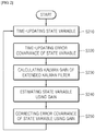
- FIG. 2 is a flowchart illustrating an operation of an extended Kalman filter according to an embodiment of the present invention.
- the extended Kalman filter is an adaptive software algorithm capable of statistically estimating the state of the system in consideration of externally measurable variables and system disturbance (external error) for dynamic systems.
- the extended Kalman filter repeatedly performs time-updating a state variable, time-updating the error covariance of the state variable, calculating a Kalman gain of the extended Kalman filter, estimating a state variable using the calculated Kalman gain, and correcting the error covariance of the state variable using the gain.
- the Extended Kalman Filter may be a method of reducing the error by repeatedly performing estimation -> correction -> estimation -> correction.
- the state equation of the extended Kalman filter is configured to include a state variable and updates the state variable over time.
- the state variables the charging capacity state variable of the energy storage system and the voltage state variable of the energy storage system are used.
- the method of calculating a charging capacity among the state variables of the energy storage system of the present invention calculates the charging capacity of the energy storage system by measuring the current of the energy storage system and integrating the measured current.
- the method of measuring the current of the energy storage system may use the current information of the energy storage system measured by the energy storage system control unit that controls and manages the energy storage system.
- the value SOC1 may be calculated by measuring the current in the energy storage system and integrating it by the logarithmic integration method.
- the charging capacity state variable of the energy storage system calculated by the above-described method may be time-updated in the extended Kalman filter by the following Equation 1.
- SOC k + 1 SOC k ⁇ i k ⁇ t Q capacity (wherein Q_capacity: capacity of secondary battery, k: time index, I[k]: current measured at time index k, t: time)
- a method of calculating the voltage state variable of the energy storage system among the state variables of the present invention may be calculated using the voltage model circuit of FIG. 5 .
- the voltage model circuit of FIG. 5 includes an open voltage source 210 that varies according to a predetermined current value flowing in the energy storage system, at least one of resistors R0 (220) and R1 (230), and at least one capacitor C1.
- the values of the resistors R0 (220) and R1 (230) and the capacitor C1 constituting the voltage model circuit may be detected in the resistance and capacitance lookup table of the energy storage systems for each temperature, which is calculated using a current with a constant value of low c-rate and stored according to an embodiment of the present invention.
- the value V1 which is an initial value of the voltage state variable
- V1 which is the voltage applied to C1
- the charging capacity state variable of the energy storage system calculated by the above-described method may be time-updated in the extended Kalman filter by the following Equation 2.
- V 1 k + 1 exp ⁇ ⁇ t R 1 C 1
- R1 and C1 are resistance and capacitance values included in the circuit model of FIG. 5 , k: time index, I[k]: current measured at time index k, t: time
- Equation 3 is an equation that expresses Equation 1 (an equation that time-updates a charging capacity state variable) and Equation 2 (an equation that time-updates a voltage state variables) used as state variables in the extended Kalman filter of the present invention by the vector state equation.
- SOC k + 1 V 1 , k + 1 1 0 0 exp ⁇ ⁇ t R 1 C 1 SOC k V 1 , k + ⁇ t Capacity R 1 1 ⁇ exp ⁇ ⁇ t R 1 C 1 I k (wherein capacity: capacity of secondary battery, R1 and C1 are resistance and capacitance values included in the circuit model of FIG. 5 , k: time index, I[k]: current measured at time index k, t: time)
- the extended Kalman filter used in the present invention may reduce the error of the charging capacity calculated by repeatedly performing the following procedure (time update (estimation) -> measurement update (correction) -> time update (estimation) -> measurement update (correction)).
- the error of the extended Kalman filter may be calculated more accurately as the error of the inputted state variable becomes smaller.
- an accurate voltage model is calculated based on the values of the resistance (R) and capacitance (C) calculated using the current with the low c-rate, and is substituted into the extended Kalman filter, so that the error may be reduced as compared with the voltage model calculated by the prior art.
- the voltage model of the energy storage system is generated using the resistance (R) and capacitance (C) of the energy storage system measured using the low c-rate, which is the characteristic of the present invention, and based on this, the result data of calculating the charging capacity of the energy storage system and the result data of the charging capacity calculated by the conventional techniques are compared and described.
- Table 1 and FIG. 6 are a table and a view for comparing the charging capacity calculated using the method of calculating the charging capacity of the energy storage system and the charging capacity calculated by the prior art (using current integration method only) through the resistance and capacitance calculation method used to calculate the voltage model of the energy storage system of the present invention.
- the external error is an error due to the current sensor.
- the temperature-dependent error value according to the presence or absence of the external error is the difference between the actually measured charging capacity value and the charging capacity value calculated by the calculation method according to the present invention or the conventional method.
- the error of the charging capacity (SOC) calculated by the conventional technique is smaller than the SOC error calculated by the method of the present invention.
- SOC error calculated by the method of the present invention is smaller than the SOC error calculated by the conventional technique.
- the error of SOC calculated by the method of the present invention is about 3% at maximum but the SCO error calculated by the prior art is more than 2 times greater, exceeding 7% at maximum.
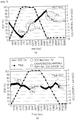
- Table 2 and FIG. 7 are a table and a view for comparing charging capacity calculated using the method of calculating the charging capacity of the energy storage system and the charging capacity calculated by the conventional algorithm (the conventional technique using a voltage model calculated at a high c-rate and a low-weight algorithm of a voltage model in a Kalman filter) through the resistance and capacitance calculation method used to calculate the voltage model of the energy storage system of the present invention by reflecting the error condition.
- the conventional algorithm the conventional technique using a voltage model calculated at a high c-rate and a low-weight algorithm of a voltage model in a Kalman filter
- Table 3 and FIG. 8 are a table and a view for comparing the results of the capacity test using the existing algorithm and the charging capacity estimation method of the present invention.
- [Table 3] SOC Max Error(%) Existing algorithm (prior art) SOC calculation method of present invention Charging direction 3.9% 2% Discharging direction 5% 2.8%
- the maximum error is 3.9% in the charging direction and the maximum error is 5% in the discharging direction.
- the maximum error is 2% in the charging direction and the maximum error is 2% in the discharging direction.
- the current charging capacity may not be accurately determined, so that the energy storage system may continue charging or discharging for up to one minute. If charging or discharging is continued in this way, even within the maximum charging capacity or maximum discharging capacity of the energy storage system, charging or discharging may last and damage the energy storage system.
- FIG. 9 is a view illustrating a configuration of an energy storage system according to an embodiment of the present invention.
- the energy storage system 10 may include a plurality of battery racks 11 and a battery section controller (BSC) 110 for controlling the plurality of battery racks.
- BSC battery section controller
- the BSC 110 may be configured including a voltage measurement unit 120 for measuring the output voltage of the energy storage system, a current measurement unit 130 for measuring the output current of the energy storage system, a storage unit 140 in which a resistance and a capacitance lookup table of a temperature-dependent energy storage system calculated with a predetermined current having a constant value are stored, and a charging capacity calculation unit 150 for calculating a charging capacity of the energy storage system based on the measured voltage and current and the calculated resistance and capacitance.
- a voltage measurement unit 120 for measuring the output voltage of the energy storage system
- a current measurement unit 130 for measuring the output current of the energy storage system
- a storage unit 140 in which a resistance and a capacitance lookup table of a temperature-dependent energy storage system calculated with a predetermined current having a constant value are stored
- a charging capacity calculation unit 150 for calculating a charging capacity of the energy storage system based on the measured voltage and current and the calculated resistance and capacitance.
- the current having the constant value uses a current having a total of 2 to 3 c-rate or more.
- the inventor of the present invention invented that the resistance and the capacitance value of the energy storage system may be more accurately calculated by applying a c-rate current lower than 2 to 3c-rate.
- the low c-rate current may be a current having a value between a minimum current value and a 2c-rate value capable of measuring the resistance and capacitance of the energy storage system.
- the current having the low c-rate may be a current of 0.1 c-rate, which corresponds to 1/10 of the current of 1 c-rate.
- the voltage measurement unit 120 may measure the first voltage, which is the voltage of the energy storage system while a predetermined current is applied to the energy storage system, and the second voltage, which is the voltage of the energy storage system after the current applied to the energy storage system is cut off.
- the current measurement unit 130 measures the output current of the energy storage system, and the measured output current of the energy storage system is used to calculate the charging capacity state variable value of the energy storage system described below.
- the lookup table stored in the storage unit 140 may be performed and stored according to the method of calculating the resistance (R) and the capacitance (C) used to calculate the voltage model of the energy storage system according to the embodiment of the present invention described above.
- the charging capacity calculation unit 150 may be configured including a voltage state variable calculation unit 151 for calculating a state variable for the voltage of the energy storage system based on the resistance and the capacitance of the lookup table and a charging capacity state variable calculation unit 152 for calculating a state variable for a charging capacity of the energy storage system using a current integration method for integrating the measured output current of the energy storage system, and may calculate the charging capacity of the energy storage system by substituting the calculated voltage state variable and the charging capacity state variable into the Kalman filter.
- the charging capacity of the specific energy storage system may be calculated by performing the procedure of the method of calculating the charging capacity of the energy storage system of the present invention described above.
- the charging capacity state variable calculated in the charging capacity state variable calculation unit may be time-updated according to Equation 1 below.
- SOC k + 1 SOC k ⁇ i k ⁇ t Q capacity (wherein Q_capacity: capacity of secondary battery, k: time index, I[k]: current measured at time index k, t: time)
- the calculated voltage state variable calculated in the voltage state variable calculation unit may be time-updated according to Equation 2 below.
- V 1 k + 1 exp ⁇ ⁇ t R 1 C 1 V 1 k + R 1 1 ⁇ exp ⁇ ⁇ t R 1 C 1 I k (wherein R1 and C1 are resistance and capacitance values included in the circuit model of FIG. 5 , k: time index, I[k]: current measured at time index k, t: time)
Landscapes
- Physics & Mathematics (AREA)
- General Physics & Mathematics (AREA)
- Engineering & Computer Science (AREA)
- Power Engineering (AREA)
- Tests Of Electric Status Of Batteries (AREA)
- Secondary Cells (AREA)
- Charge And Discharge Circuits For Batteries Or The Like (AREA)
- Measurement Of Resistance Or Impedance (AREA)
Abstract
Description
- The present invention relates to an apparatus and a method for calculating the charging capacity of an energy storage system.
- More particularly, the present invention relates to a device and method for accurately calculating a charging capacity of an energy storage system by increasing the accuracy of a voltage model used in an extended Kalman filter.
- With the development of the industry, the demand for electric power is increasing, and the gap of electric power usage amounts between day and night, season, and day is increasing. Recently, for this reason, a number of techniques are rapidly being developed to reduce the peak load by utilizing the surplus electric power of the system.
- A typical example of these technologies is an energy storage system in which the surplus electric power of the system is stored in the battery or the insufficient electric power of the system is supplied from the battery.
- In order to maintain the life of the energy storage system for a long time and to use it safely, the energy storage system must be operated within the proper charging capacity range, and the life time of the energy storage system greatly changes according to the number of charging/discharging cycles.
- Therefore, it is important to understand the state of the energy storage system by measuring the current, voltage and temperature thereof and accurately measuring the charging capacity (SOC) of the energy storage system.
- A conventional method of calculating the charging capacity (SOC) of an energy storage system was a current integration method. However, in the conventional current integration method, there is an error in the current sensor for measuring the current, and in the course of integrating the current, the error of the current sensor is also accumulated, so that it is difficult to calculate the accurate charging capacity.
- As another conventional technique for solving such a conventional problem, there were a current integration method for calculating a charging capacity based on a current measured by the current sensor when the charging capacity of the energy storage system is calculated and a method of calculating the charging capacity by substituting the voltage model of the energy storage system into the extended Kalman filter.
- However, even in the technology using the current integration method and the voltage model of the energy storage system in the conventional extended Kalman filter, since the accuracy of the resistance (R) and capacitance (C) used to calculate the voltage model of the energy storage system is low, there is still a problem that an error occurs in the final charging capacity.
- Therefore, the present invention proposes a device and method for reducing the charging capacity error of an energy storage system by accurately calculating the resistance (R) and capacitance (C) used to calculate the voltage model of the energy storage system and performing final calculation using the Kalman filter having a high specific weight of the voltage model.
- The present invention provides a device and method for accurately calculating a charging capacity of an energy storage system by accurately calculating a voltage model of an energy storage system.
- More particularly, the present invention provides a device and method for accurately calculating a charging capacity by accurately calculating a resistance (R) and a capacitance (C) used in a voltage model of an energy storage system and substituting an accurate voltage model into an extended Kalman filter.
- Embodiments of the present invention provide a method of calculating a resistance (R) and a capacitance (C) of an energy storage system. The method includes: a current application step of applying a predetermined current having a constant value to the energy storage system; a first voltage measurement step of measuring a voltage of the energy storage system while a predetermined current having a constant value is applied to the energy storage system; a second voltage measurement step of measuring a voltage of the energy storage system after breaking a predetermined current having a constant value applied to the energy storage system; and a resistance (R) and capacitance (C) calculation step of calculating a resistance (R) and a capacitance (C) of the energy storage system based on the voltage of the energy storage system measured in the first voltage measurement step, the voltage of the energy storage system measured in the second voltage measurement step, and the predetermined current having the constant value.
- The predetermined current having a constant value applied in the current application step may be a current between a minimum current value and a 2c-rate, which is capable of measuring a resistance and a capacitance value of the energy storage system.
- The predetermined current having a constant value applied in the current application step may be a current between a minimum current value and a 0.1c-rate, which is capable of measuring a resistance and a capacitance value of the energy storage system.
- The method may further include: a state variable calculation step of calculating a state variable of the extended Kalman filter using the resistance and the capacitance of the energy storage system; and an energy storage system charging capacity calculation step of substituting the state variable into the extended Kalman filter to calculate a charging capacity of the energy storage system.
- The extended Kalman filter may repeatedly perform: time-updating the state variable; time-updating the error covariance of the state variable; calculating a Kalman gain of the extended Kalman filter; estimating a state variable using the gain; and correcting the error covariance of the state variable using the gain.
- The state variable calculation step may include: a charging capacity state variable calculation step of generating a state variable for the charging capacity of the energy storage system; and a voltage state variable calculation step of generating a state variable for the voltage of the energy storage system.
- The charging capacity state variable calculation step may calculate a charging capacity state variable using a current integration method of integrating the current measured in the energy storage system, wherein the calculated charging capacity state variable may be time-updated according to
Equation 1 below.
- (wherein Q_capacity: capacity of secondary battery, k: time index, I[k]: current measured at time index k, t: time)
- The voltage state variable calculation step may calculate a voltage state variable of the energy storage system using a voltage model circuit, wherein the calculated voltage state variable may be time-updated according to
Equation 2 below.
(wherein R1 and C1 are resistance and capacitance values included in the circuit model ofFIG. 5 , k: time index, I[k]: current measured at time index k, t: time) - The voltage model circuit may include: an open voltage source for outputting a predetermined voltage according to a current value flowing through the energy storage system; one or more resistors; and one or more capacitors.
- In other embodiments of the present invention, an energy storage system includes: a plurality of battery racks; and a battery section controller (BSC) for controlling the plurality of battery racks, wherein the BSC includes: a voltage measurement unit for measuring the output voltage of the energy storage system; a current measurement unit for measuring the output current of the energy storage system; a storage unit in which a resistance (R) and a capacitance (C) look-up table of a temperature-dependent energy storage system calculated with a predetermined current having a constant value are stored; and a charging capacity calculation unit for calculating a charging capacity of the energy storage system based on the lookup table.
- The voltage measurement unit may measure: a first voltage that is a voltage of the energy storage system while a predetermined current is applied to the energy storage system; and a second voltage that is a voltage of the energy storage system after the current applied to the energy storage system is cut off.
- The charging capacity calculation unit may include: a voltage state variable calculation unit for calculating a state variable for a voltage of the energy storage system based on a resistance and a capacitance of the lookup table; and a charging capacity state variable calculation unit for calculating a state variable for a charging capacity of the energy storage system using a current integration method for integrating the measured output current, wherein the calculated voltage state variable and the charging capacity state variable may be substituted into the Kalman filter to calculate the charging capacity of the energy storage system.
- The present invention may accurately calculate the voltage model of the energy storage system by accurately calculating the resistance (R) and the capacitance (C) used in the voltage model of the energy storage system.
- Further, the present invention may accurately calculate the charging capacity of the energy storage system by calculating the accurate voltage model of the energy storage system.
-
-
FIG. 1 is a flowchart illustrating a method of calculating a resistance (R) and a capacitance (C) used for calculating a voltage model of the energy storage system of the present invention. -
FIG. 2 is a flowchart illustrating an operation of an extended Kalman filter according to an embodiment of the present invention. -
FIG. 3 is a view illustrating an actual experimental method (DCPR) for calculating a resistance R and a capacitance C used for calculating a voltage model of an energy storage system according to an embodiment of the present invention. -
FIG. 4 is a graph comparing changes in charging capacity after discharging calculated based on the conventional voltage model and changes in charging capacity calculated through the voltage model calculating method of the present invention. -
Fig. 5 is a voltage model circuit for calculating the voltage of the energy storage system according to the embodiment of the present invention. -
FIG. 6 is a view for comparing the charging capacity calculated using the method of calculating the charging capacity of the energy storage system and the charging capacity calculated by the prior art (using current integration method only) through the resistance and capacitance calculation method used to calculate the voltage model of the energy storage system of the present invention. -
FIG. 7 is a view for comparing charging capacity calculated using the method of calculating the charging capacity of the energy storage system and the charging capacity calculated by the conventional algorithm (the conventional technique using a voltage model calculated at a high c-rate and a low-weight algorithm of a voltage model in a Kalman filter) through the resistance and capacitance calculation method used to calculate the voltage model of the energy storage system of the present invention by reflecting the error condition. -
FIG. 8 is a view for comparing the results of the capacity test using the existing algorithm and the charging capacity estimation method of the present invention. -
FIG. 9 is a view illustrating a configuration of an energy storage system according to an embodiment of the present invention. - Hereinafter, embodiments of the present invention will be described in detail with reference to the accompanying drawings so that those skilled in the art may easily carry out the present invention. The present invention may, however, be embodied in different forms and should not be constructed as limited to the embodiments set forth herein. Parts not relating to description are omitted in the drawings in order to clearly describe the present invention and like reference numerals refer to like elements throughout.
- Although the terms "initial," "second," etc., may be used herein to describe various elements, these elements should not be limited by these terms. The above terms are used only to distinguish one component from another. For example, an initial component may be referred to as a second component and vice versa without departing from the scope of the present invention. Terms used in this specification are used to describe specific embodiments, and are not intended to limit the scope of the present invention. The singular expressions include plural expressions unless the context clearly dictates otherwise.
- Throughout the specification, when a portion is referred to as being "connected" to another portion, it includes not only "directly connected" but also "electrically connected" with another element therebetween. Furthermore, when it is described that one comprises (or includes or has) some elements, it should be understood that it may comprise (or include or has) only those elements, or it may comprise (or include or have) other elements as well as those elements if there is no specific limitation. The term "∼ing operation" or "operation of ∼ing" used throughout the specification does not mean "operation for ∼ing".
- Terms used in this specification may be currently widely used general terms in consideration of functions in the present invention but may vary according to the intents of those skilled in the art, precedents, or the advent of new technology. Additionally, in certain cases, there may be terms the applicant selects arbitrarily and in this case, their meanings are described in a corresponding description part of the present invention. Accordingly, terms used in the present invention should be defined based on the meaning of the term and the entire contents of the present invention instead of the simple term name.
- The charging capacity of an energy storage system was calculated using a current integration method as a method of calculating the charging capacity of a conventional energy storage system. The current integration method determines the charging capacity by integrating the charging current and the discharging current with time. However, in relation to the current integrating method, there is an error in the current sensor for measuring the charging current and the discharging current. Such error accumulates as the time for integrating the current accumulates, so that the accuracy of the charging capacity finally calculated by the current accumulation method is lowered.
- Conventionally, in order to solve such a problem, both the voltage model and the current integration method of the energy magnetic field system were substituted into the extended Kalman filter to obtain a more accurate charging capacity.
- But, conventionally, since the resistance R and the capacitance C used to calculate the voltage model of the energy storage system, which are substituted for the extended Kalman filter, are not calculated accurately, there was still an error in the charging capacity of the energy storage system.
- Therefore, the present invention proposes a method of accurately calculating the resistance (R) and the capacitance (C) used to calculate the voltage model of the energy storage system.
-
FIG. 1 is a method of calculating a resistance (R) and a capacitance (C) used to calculate a voltage model of the energy storage system of the present invention. - The present invention uses the resistance (R) and the capacitance (C) of the energy storage system to calculate the voltage model of the energy storage system.
- The method of calculating the resistance (R) and capacitance (C) of the energy storage system of the present invention is characterized by using a low c-rate current.
- In the present invention, the method of calculating the resistance (R) and the capacitance (C) of the energy storage system may be calculated using the DCPR method as shown in
FIG. 3 . - Hereinafter, a method of calculating the resistance (R) and the capacitance (C) of the energy storage system of the present invention will be described with reference to
FIG. 1 andFIG. 3 . - The present invention applies a predetermined current having a constant value to an energy storage system, measures the voltage change of the energy storage system, and based on this, calculates the resistance (R) and the capacitance (C) of the energy storage system.
- The current application step is a step of applying a predetermined current having a constant value to an energy storage system charged to a predetermined charging capacity. After applying a predetermined current having a constant value to the energy storage system in such a way, the first voltage measurement step is performed. At this time, the predetermined current having the constant value to be applied is a current having a low c-rate. The c-rate may mean the intensity of the current.
- The current having the constant value applied uses a current having a total of 2 to 3 c-rate or more. However, the inventor of the present invention invented that the resistance and the capacitance value of the energy storage system may be more accurately calculated by applying a c-rate current lower than 2 to 3c-rate.
- Accordingly, in the present invention, the low c-rate current may be a current having a value between a minimum current value and a 2c-rate value capable of measuring the resistance and capacitance of the energy storage system.
- Preferably, the current having the low c-rate may be a current of 0.1 c-rate, which corresponds to 1/10 of the current of 1 c-rate.
- When a current having a high c-rate is applied, the voltage of the energy storage system changes after the application of the current. As compared to this, when a current having a low c-rate is applied, after the current application is completed, the voltage of the energy storage system may be stabilized quickly, and the more accurate resistance (R) and capacitance (C) of an energy storage system may be calculated.
- The first voltage measurement step of the present invention is a step of measuring a voltage of the energy storage system while a predetermined current having a constant value flows through the energy storage system.
- Specifically, when a predetermined current having a constant value is applied to the energy storage system charged to a predetermined charging capacity in the voltage application step, the voltage of the energy storage system varies by a predetermined value. The voltage of the energy storage system measured at this time is used in the step of calculating the resistance (R) and the capacitance (C), which will be described later.
- The second voltage measurement step of the present invention is a step of terminating the application of a predetermined current having a constant value after the first voltage measurement step and measuring the voltage of the energy storage system.
- Specifically, when a predetermined current having a constant value is applied to the energy storage system and then cut off, the voltage of the energy storage system changes. For example, when current is applied in the charging direction and current is cut off, the voltage of the energy storage system may drop, and when a current is applied in the discharging direction and the current is cut off, the voltage of the energy storage system may rise. The voltage change of the energy storage system measured at this time is used in the step of calculating the resistance (R) and the capacitance (C), which will be described later.
- The resistance (R) and capacitance (C) calculation step is a step of calculating the resistance (R) and capacitance (C) of the energy storage system based on the voltage of the energy storage system measured in the first voltage measurement step, the voltage of the energy storage system measured in the second voltage measurement step, and the predetermined current having a constant value. Specifically, since a predetermined current having a constant value applied to the energy storage system is known and a voltage corresponding to the flow of a predetermined current having the constant value is known, the resistance (R) and the capacitance (C) of the energy storage system may be calculated.
- For example, in the circuit of
FIG. 5 , the Vcell is a sum of an OCV voltage, a voltage applied to R0, and a voltage applied to C1. On the other hand, the OCV value is a value preset according to the charging capacity of the battery cell. The resistance value of R0 is a value obtained by dividing the difference between the Vcell voltage Vt measured at time t and the Vcell voltage Vt+1 measured at time t+1 by the low c-rate current flowing in the circuit. The voltage applied to R0 is also known. Therefore, since the voltage value and the current value applied to C1 are known, the R1 value and the C1 value may be calculated. - In this way, the resistance (R) and the capacitance (C) of the energy storage system, which are repeatedly calculated while changing the temperature of the energy storage system, may be stored in the form of a resistance and capacitance lookup table of the temperature storage system.
- Meanwhile, since a current having a low c-rate (0.1c-rate) is used in the present invention, the voltage of the energy storage system measured in the second voltage measurement step is quickly stabilized after the current does not flow, the voltage of the energy storage system when the current flows and the voltage of the energy storage system when the current does not flow are accurately measured.
- Therefore, if the voltage model of the energy storage system is calculated using the resistance (R) and the capacitance (C) of the energy storage system and based on this, the charging capacity of the energy storage system is calculated, the charging capacity of the energy storage system may be accurately calculated.
- Meanwhile, in the present invention, there may be a predetermined rest time between the current application step and the first voltage measurement step and between the first voltage measurement step and the second voltage measurement step.
- Hereinafter, a method of accurately calculating the voltage model of the energy storage system using the resistance (R) and capacitance (C) calculation methods of the energy storage system of the present invention and based on this, calculating the charging capacity of the energy storage system will be described.
- The charging capacity of the conventional energy storage system is calculated by substituting the voltage and current integration models into the state variables of the extended Kalman filter. However, conventionally, the values of the resistance (R) and capacitance (C) used to calculate the voltage model are not accurately calculated, so that an error occurs in the calculated charging capacity.
- Specifically, conventionally, when calculating the resistance (R) and the capacitance (C) used to calculate the voltage model, they were calculated using high c-rate currents of about 2 to 3 c-rates.
- However, in the present invention, when calculating the resistance (R) and the capacitance (C) used in calculating the voltage model, the calculation accuracy of the resistance (R) and the capacitance (C) is increased by using a low c-rate current.
- On the other hand, the low c-rate current may be a value between a minimum current value and a 2c-rate capable of measuring the resistance and capacitance of the energy storage system.
- Preferably, the current having the low c-rate may be a current of 0.1 c-rate, which corresponds to 1/10 of the current of 1 c-rate.
FIG. 4 is a graph comparing changes in charging capacity after discharging calculated based on the conventional voltage model and changes in charging capacity calculated through the voltage model calculating method of the present invention. - Referring to
FIG. 4 , when the voltage model is calculated based on the resistance R and the capacitance C calculated by the conventional method, the rate of change of the charging capacity (3%) calculated by the extended Kalman filter after discharging is large. - It is normal that there is no change in the charging capacity after discharging but the conventional method has a rate of change of 3%, so that the conventional method is inaccurate.
- However, as in the above present invention, when the voltage model is calculated based on the resistance R and the capacitance C calculated using the low c-rate current, the rate of change of the charging capacity (0.5%) calculated by the extended Kalman filter after discharging is very small.
- That is, since the rate of change of the charging capacity is small after discharging, the present invention has an effect of more accurately calculating the charging capacity.
- Therefore, by using the charging capacity calculating method of the energy storage system of the present invention, it is possible to calculate the charging capacity more accurately than the conventional one.
-
FIG. 2 is a flowchart illustrating an operation of an extended Kalman filter according to an embodiment of the present invention. - On the other hand, the extended Kalman filter is an adaptive software algorithm capable of statistically estimating the state of the system in consideration of externally measurable variables and system disturbance (external error) for dynamic systems.
- Specifically, the extended Kalman filter repeatedly performs time-updating a state variable, time-updating the error covariance of the state variable, calculating a Kalman gain of the extended Kalman filter, estimating a state variable using the calculated Kalman gain, and correcting the error covariance of the state variable using the gain.
- That is, the Extended Kalman Filter may be a method of reducing the error by repeatedly performing estimation -> correction -> estimation -> correction.
- In the present invention, the state equation of the extended Kalman filter is configured to include a state variable and updates the state variable over time. As the state variables, the charging capacity state variable of the energy storage system and the voltage state variable of the energy storage system are used.
- The method of calculating a charging capacity among the state variables of the energy storage system of the present invention calculates the charging capacity of the energy storage system by measuring the current of the energy storage system and integrating the measured current.
- The method of measuring the current of the energy storage system may use the current information of the energy storage system measured by the energy storage system control unit that controls and manages the energy storage system.
- That is, in relation to the initial value of the charging capacity state variable, the value SOC1 may be calculated by measuring the current in the energy storage system and integrating it by the logarithmic integration method.
- The charging capacity state variable of the energy storage system calculated by the above-described method may be time-updated in the extended Kalman filter by the following
Equation 1.
(wherein Q_capacity: capacity of secondary battery, k: time index, I[k]: current measured at time index k, t: time) - A method of calculating the voltage state variable of the energy storage system among the state variables of the present invention may be calculated using the voltage model circuit of
FIG. 5 . - The voltage model circuit of
FIG. 5 includes anopen voltage source 210 that varies according to a predetermined current value flowing in the energy storage system, at least one of resistors R0 (220) and R1 (230), and at least one capacitor C1. The values of the resistors R0 (220) and R1 (230) and the capacitor C1 constituting the voltage model circuit may be detected in the resistance and capacitance lookup table of the energy storage systems for each temperature, which is calculated using a current with a constant value of low c-rate and stored according to an embodiment of the present invention. - When values of the resistance and capacitance constituting the voltage model circuit are detected in the resistance and capacitance lookup tables of the energy storage system for each temperature, the value V1, which is an initial value of the voltage state variable, may be calculated.
- Specifically, since the values of R1, C1, and RO and the currents flowing through R1, C1, and RO, respectively, are known, the value of V1, which is the voltage applied to C1, may be calculated.
- On the other hand, the charging capacity state variable of the energy storage system calculated by the above-described method may be time-updated in the extended Kalman filter by the following
Equation 2.
(wherein R1 and C1 are resistance and capacitance values included in the circuit model ofFIG. 5 , k: time index, I[k]: current measured at time index k, t: time) - On the other hand,
Equation 3 is an equation that expresses Equation 1 (an equation that time-updates a charging capacity state variable) and Equation 2 (an equation that time-updates a voltage state variables) used as state variables in the extended Kalman filter of the present invention by the vector state equation.
(wherein capacity: capacity of secondary battery, R1 and C1 are resistance and capacitance values included in the circuit model ofFIG. 5 , k: time index, I[k]: current measured at time index k, t: time) - The charging capacity of the energy storage system may be accurately calculated by inserting
Equation 3 into the initial value of the extended Kalman filter (when k = 0). - The extended Kalman filter used in the present invention may reduce the error of the charging capacity calculated by repeatedly performing the following procedure (time update (estimation) -> measurement update (correction) -> time update (estimation) -> measurement update (correction)).
Time Update("Predict) Measurement Update("Correct") (1)Project the state ahead (1)Compute the Kalman gain x̂k -=Ax̂ k-1 + Buk Kk = Pk -HT (HPk -HT + R)-1 (2)Project the error covariance ahead ↔ (2)Update estimate with measurement Pk - =AP k-1 AT +Q x̂k=x̂k -+Kk x(zk - Hx̂k -) (3)Update the error covariance Pk =(I-KkH) Pk - - (P: error covariance, H: transform coefficient, K: Kalman gain, Q: standard deviation with respect to true value, A: state variable (Equation 3), z: observed value, R: error from observed true value, k: degree of step, u: additional input value, I: unit matrix)
- Then, the error of the extended Kalman filter may be calculated more accurately as the error of the inputted state variable becomes smaller.
- In other words, in the present invention, an accurate voltage model is calculated based on the values of the resistance (R) and capacitance (C) calculated using the current with the low c-rate, and is substituted into the extended Kalman filter, so that the error may be reduced as compared with the voltage model calculated by the prior art.
- Hereinafter, the voltage model of the energy storage system is generated using the resistance (R) and capacitance (C) of the energy storage system measured using the low c-rate, which is the characteristic of the present invention, and based on this, the result data of calculating the charging capacity of the energy storage system and the result data of the charging capacity calculated by the conventional techniques are compared and described.
- Table 1 and
FIG. 6 are a table and a view for comparing the charging capacity calculated using the method of calculating the charging capacity of the energy storage system and the charging capacity calculated by the prior art (using current integration method only) through the resistance and capacitance calculation method used to calculate the voltage model of the energy storage system of the present invention.[Table] Experimental environment Temperature 25 degrees 35 degrees C-rate 0.1C 0.3 C 1C 0.1C 0.3 C 1C Method of present invention External error X 2.59% 2.21% 2.79% 1.8% 1.37% 2.32% External error O 4.88% 4.11% 4.56% 4.99% 4.07% 4.09% SOC error increase amount 2.29% 1.90% 1.77% 3.19% 2.70% 1.77% Prior art External error X 1.02% 1.11% 0.85% 0.98% 1.19% 1.52% External error O 7.55% 7.91% 8.04% 7.98% 8.42% 8.92% SOC error increase amount 6.53% 6.80% 7.19% 7.00% 7.23% 7.40% - In Table 1, the external error is an error due to the current sensor. On the other hand, the temperature-dependent error value according to the presence or absence of the external error is the difference between the actually measured charging capacity value and the charging capacity value calculated by the calculation method according to the present invention or the conventional method.
- Referring to Table 1 and
FIG. 6 , if there is no external error (there is no error in the current sensor), it may be confirmed that the error of the charging capacity (SOC) calculated by the conventional technique is smaller than the SOC error calculated by the method of the present invention. In comparison to this, if there is an external error, it may be confirmed that the SOC error calculated by the method of the present invention is smaller than the SOC error calculated by the conventional technique. Further, when an external error exists, even if looking at the rate of SOC error growth, the error of SOC calculated by the method of the present invention is about 3% at maximum but the SCO error calculated by the prior art is more than 2 times greater, exceeding 7% at maximum. - Therefore, in the absence of an external error, the prior art is more accurate, but in an environment used in an actual energy storage system, an error occurs in the current sensor, so that the method of calculating the charging capacity of an energy storage system in an actual use environment is more accurate than the method of the present invention.
- Meanwhile, Table 2 and
FIG. 7 are a table and a view for comparing charging capacity calculated using the method of calculating the charging capacity of the energy storage system and the charging capacity calculated by the conventional algorithm (the conventional technique using a voltage model calculated at a high c-rate and a low-weight algorithm of a voltage model in a Kalman filter) through the resistance and capacitance calculation method used to calculate the voltage model of the energy storage system of the present invention by reflecting the error condition.[Table 2] Error condition Existing algorithm (prior art) SOC calculation method of present invention In current sensor specification, maximum ±3 % error At 3%, Max error 2.5% At 3%, Max error 1.0% Customer requirement SOH error ± 5% Tolerance of process capacity ± 2.5% At 7.5%, Max error 9%At 7.5%, Max error 1.5% - Referring to Table 2 and
FIG. 7 , when the current sensor has an error of +-3% (external error) (FIG. 7(a) ), the maximum error of the charging capacity calculated by the existing algorithm is 2.5% but when the charging capacity (SOC) calculating method of the present invention is used (FIG. 7(b) ), the maximum error of the charging capacity is 1% so that it may be confirmed that the charging capacity calculation method of the present invention has less error than the existing algorithm. In addition, when the degradation (SOH) error (external error) of the energy storage system is +-5% and the tolerance range (external error) of the process capacity generated in the fixation is + -2.5%, the maximum error of the charging capacity calculated by the existing algorithm is 9% but when the charging capacity calculation method of the present invention is used, it may be confirmed that the error of charging capacity is 1.5% at maximum. - As a result, as the external error is larger, it may be confirmed that the use of the charging capacity calculation method of the present invention produces less error as compared to measuring charging capacity using existing algorithms.
- On the other hand, Table 3 and
FIG. 8 are a table and a view for comparing the results of the capacity test using the existing algorithm and the charging capacity estimation method of the present invention.[Table 3] SOC Max Error(%) Existing algorithm (prior art) SOC calculation method of present invention Charging direction 3.9% 2 % Discharging direction 5% 2.8% - As shown in Table 3 and
FIG. 8 , according to the capacity test using the existing algorithm, it may be confirmed that the maximum error is 3.9% in the charging direction and the maximum error is 5% in the discharging direction. In comparison to this, according to a result of the capacity test using the charging capacity calculating method of the present invention, it may be confirmed that the maximum error is 2% in the charging direction and the maximum error is 2% in the discharging direction. - As a result, it may be confirmed that the use of the charging capacity calculating method of the present invention results in a small error in the capacity test result for both charging/discharging.
- On the other hand, in the conventional algorithm, when the maximum error as described above occurs, the current charging capacity may not be accurately determined, so that the energy storage system may continue charging or discharging for up to one minute. If charging or discharging is continued in this way, even within the maximum charging capacity or maximum discharging capacity of the energy storage system, charging or discharging may last and damage the energy storage system.
-
FIG. 9 is a view illustrating a configuration of an energy storage system according to an embodiment of the present invention. - Hereinafter, an energy storage system according to an embodiment of the present invention will be described with reference to
FIG. 9 . - The
energy storage system 10 according to an embodiment of the present invention may include a plurality ofbattery racks 11 and a battery section controller (BSC) 110 for controlling the plurality of battery racks. - Specifically, the
BSC 110 may be configured including avoltage measurement unit 120 for measuring the output voltage of the energy storage system, acurrent measurement unit 130 for measuring the output current of the energy storage system, astorage unit 140 in which a resistance and a capacitance lookup table of a temperature-dependent energy storage system calculated with a predetermined current having a constant value are stored, and a chargingcapacity calculation unit 150 for calculating a charging capacity of the energy storage system based on the measured voltage and current and the calculated resistance and capacitance. - The current having the constant value uses a current having a total of 2 to 3 c-rate or more. However, the inventor of the present invention invented that the resistance and the capacitance value of the energy storage system may be more accurately calculated by applying a c-rate current lower than 2 to 3c-rate.
- Accordingly, in the present invention, the low c-rate current may be a current having a value between a minimum current value and a 2c-rate value capable of measuring the resistance and capacitance of the energy storage system.
- Preferably, the current having the low c-rate may be a current of 0.1 c-rate, which corresponds to 1/10 of the current of 1 c-rate.
- Meanwhile, the
voltage measurement unit 120 may measure the first voltage, which is the voltage of the energy storage system while a predetermined current is applied to the energy storage system, and the second voltage, which is the voltage of the energy storage system after the current applied to the energy storage system is cut off. - Meanwhile, the
current measurement unit 130 measures the output current of the energy storage system, and the measured output current of the energy storage system is used to calculate the charging capacity state variable value of the energy storage system described below. - The lookup table stored in the
storage unit 140 may be performed and stored according to the method of calculating the resistance (R) and the capacitance (C) used to calculate the voltage model of the energy storage system according to the embodiment of the present invention described above. - Meanwhile, the charging
capacity calculation unit 150 may be configured including a voltage statevariable calculation unit 151 for calculating a state variable for the voltage of the energy storage system based on the resistance and the capacitance of the lookup table and a charging capacity statevariable calculation unit 152 for calculating a state variable for a charging capacity of the energy storage system using a current integration method for integrating the measured output current of the energy storage system, and may calculate the charging capacity of the energy storage system by substituting the calculated voltage state variable and the charging capacity state variable into the Kalman filter. - The charging capacity of the specific energy storage system may be calculated by performing the procedure of the method of calculating the charging capacity of the energy storage system of the present invention described above.
- For example, the charging capacity state variable calculated in the charging capacity state variable calculation unit may be time-updated according to
Equation 1 below.
(wherein Q_capacity: capacity of secondary battery, k: time index, I[k]: current measured at time index k, t: time) - Meanwhile, the calculated voltage state variable calculated in the voltage state variable calculation unit may be time-updated according to
Equation 2 below.
(wherein R1 and C1 are resistance and capacitance values included in the circuit model ofFIG. 5 , k: time index, I[k]: current measured at time index k, t: time) - On the other hand, although the technical idea of the present invention is specifically described with reference to the above embodiments, it should be noted that the above embodiments are for the purpose of explanation and not for the purpose of limitation. It will be apparent to those skilled in the art that various modifications and variations may be made in the present invention without departing from the spirit and scope of the invention.
Claims (16)
- A method of calculating a resistance (R) and a capacitance (C) of an energy storage system, the method comprising:a current application step of applying a predetermined current having a constant value to the energy storage system;a first voltage measurement step of measuring a voltage of the energy storage system while a predetermined current having a constant value is applied to the energy storage system;a second voltage measurement step of measuring a voltage of the energy storage system after breaking a predetermined current having a constant value applied to the energy storage system; anda resistance (R) and capacitance (C) calculation step of calculating a resistance (R) and a capacitance (C) of the energy storage system based on the voltage of the energy storage system measured in the first voltage measurement step, the voltage of the energy storage system measured in the second voltage measurement step, and the predetermined current having the constant value.
- The method of claim 1, wherein the predetermined current having a constant value applied in the current application step is a current between a minimum current value and a 2c-rate, which is capable of measuring a resistance and a capacitance value of the energy storage system.
- The method of claim 2, wherein the predetermined current having a constant value applied in the current application step is a current between a minimum current value and a 0.1c-rate, which is capable of measuring a resistance and a capacitance value of the energy storage system.
- The method of claim 1, further comprising:a state variable calculation step of calculating a state variable of the extended Kalman filter using the resistance and the capacitance of the energy storage system; andan energy storage system charging capacity calculation step of substituting the state variable into the extended Kalman filter to calculate a charging capacity of the energy storage system.
- The method of claim 4, wherein the extended Kalman filter repeatedly performs:time-updating the state variable;time-updating the error covariance of the state variable;calculating a Kalman gain of the extended Kalman filter;estimating a state variable using the gain; andcorrecting the error covariance of the state variable using the gain.
- The method of claim 4, wherein the state variable calculation step comprises:a charging capacity state variable calculation step of generating a state variable for the charging capacity of the energy storage system; anda voltage state variable calculation step of generating a state variable for the voltage of the energy storage system.
- The method of claim 6, wherein the charging capacity state variable calculation step calculates a charging capacity state variable using a current integration method of integrating the current measured in the energy storage system,
wherein the calculated charging capacity state variable is time-updated according to Equation 1 below.
- The method of claim 6, wherein the voltage state variable calculation step calculates a voltage state variable of the energy storage system using a voltage model circuit,
wherein the calculated voltage state variable is time-updated according to Equation 2 below.
- The method of claim 8, wherein the voltage model circuit comprises:an open voltage source for outputting a predetermined voltage according to a current value flowing through the energy storage system;one or more resistors; andone or more capacitors.
- An energy storage system comprising:a plurality of battery racks; anda battery section controller (BSC) for controlling the plurality of battery racks,wherein the BSC comprises:a voltage measurement unit for measuring the output voltage of the energy storage system;a current measurement unit for measuring the output current of the energy storage system;a storage unit in which a resistance (R) and a capacitance (C) look-up table of a temperature-dependent energy storage system calculated with a predetermined current having a constant value are stored; anda charging capacity calculation unit for calculating a charging capacity of the energy storage system based on the lookup table.
- The energy storage system of claim 10, wherein the predetermined current having the constant value is a current between a minimum current value capable of measuring the resistance and capacitance value of the energy storage system to 2c-rate.
- The energy storage system of claim 11, wherein the predetermined current having the constant value is a current between a minimum current value capable of measuring the resistance and capacitance value of the energy storage system to 0.1c-rate.
- The energy storage system of claim 10, wherein the voltage measurement unit measures:a first voltage that is a voltage of the energy storage system while a predetermined current is applied to the energy storage system; anda second voltage that is a voltage of the energy storage system after the current applied to the energy storage system is cut off.
- The energy storage system of claim 10, wherein the charging capacity calculation unit comprises:a voltage state variable calculation unit for calculating a state variable for a voltage of the energy storage system based on a resistance and a capacitance of the lookup table; anda charging capacity state variable calculation unit for calculating a state variable for a charging capacity of the energy storage system using a current integration method for integrating the measured output current,wherein the calculated voltage state variable and the charging capacity state variable are substituted into the Kalman filter to calculate the charging capacity of the energy storage system.
- The energy storage system of claim 14, wherein the charging capacity state variable calculated in the charging capacity state variable calculation unit is time-updated according to Equation 1 below.

- The energy storage system of claim 14, wherein the calculated voltage state variable calculated in the voltage state variable calculation unit is time-updated according to Equation 2 below.

Applications Claiming Priority (3)
| Application Number | Priority Date | Filing Date | Title |
|---|---|---|---|
| KR20180020003 | 2018-02-20 | ||
| KR1020190019143A KR102783337B1 (en) | 2018-02-20 | 2019-02-19 | Apparatus and method for calculating State Of Charge |
| PCT/KR2019/002070 WO2019164263A1 (en) | 2018-02-20 | 2019-02-20 | Charge capacity calculation device and method for energy storage system |
Publications (3)
| Publication Number | Publication Date |
|---|---|
| EP3730957A1 true EP3730957A1 (en) | 2020-10-28 |
| EP3730957A4 EP3730957A4 (en) | 2021-03-17 |
| EP3730957B1 EP3730957B1 (en) | 2025-07-30 |
Family
ID=67775309
Family Applications (1)
| Application Number | Title | Priority Date | Filing Date |
|---|---|---|---|
| EP19756861.1A Active EP3730957B1 (en) | 2018-02-20 | 2019-02-20 | Charge capacity calculation device and method for energy storage system |
Country Status (8)
| Country | Link |
|---|---|
| US (1) | US11467217B2 (en) |
| EP (1) | EP3730957B1 (en) |
| JP (2) | JP2020530905A (en) |
| KR (1) | KR102783337B1 (en) |
| CN (2) | CN121856797A (en) |
| ES (1) | ES3037985T3 (en) |
| HU (1) | HUE072540T2 (en) |
| PL (1) | PL3730957T3 (en) |
Families Citing this family (8)
| Publication number | Priority date | Publication date | Assignee | Title |
|---|---|---|---|---|
| KR102458526B1 (en) * | 2018-02-07 | 2022-10-25 | 주식회사 엘지에너지솔루션 | Apparatus and method for estimating soc base on operating state of battery |
| ES2991479T3 (en) * | 2019-08-23 | 2024-12-03 | Lg Energy Solution Ltd | Method for predicting the health status of a battery and battery group that employs it |
| KR102850998B1 (en) * | 2020-07-09 | 2025-08-27 | 한국전기연구원 | Smart battery management system for fire prevention |
| KR102802131B1 (en) * | 2022-01-12 | 2025-05-02 | 한국전력공사 | Compensation method and system of input value errors of kalman filter for estimating state of charge of supercapacitor |
| KR102892040B1 (en) | 2022-05-25 | 2025-11-26 | 삼성에스디아이 주식회사 | Method of estimating state of charge of battery |
| WO2025178338A1 (en) * | 2024-02-21 | 2025-08-28 | 주식회사 엘지에너지솔루션 | Battery diagnostic apparatus and method thereof |
| CN119401530B (en) * | 2024-12-31 | 2025-07-01 | 浙江卧龙储能系统有限公司 | Estimation method and device of SOE of energy storage system and related equipment |
| CN120742141B (en) * | 2025-09-05 | 2025-12-26 | 宁波海晟能源发展有限公司 | Energy storage prediction method, system and equipment |
Family Cites Families (35)
| Publication number | Priority date | Publication date | Assignee | Title |
|---|---|---|---|---|
| US7301307B2 (en) | 2004-06-25 | 2007-11-27 | Nokia Corporation | Method and apparatus to charge a battery using determination of battery load current |
| KR100793616B1 (en) | 2005-06-13 | 2008-01-10 | 주식회사 엘지화학 | Apparatus and method for testing state of charge in battery |
| JP4884945B2 (en) * | 2006-11-30 | 2012-02-29 | 三菱重工業株式会社 | Charging state prediction program, overhead line-less traffic system and charging method thereof |
| JP5091067B2 (en) * | 2008-09-17 | 2012-12-05 | カルソニックカンセイ株式会社 | Method and apparatus for estimating remaining battery level |
| US8170818B2 (en) * | 2010-03-10 | 2012-05-01 | GM Global Technology Operations LLC | Battery state estimator using multiple sampling rates |
| US9354277B2 (en) * | 2010-10-29 | 2016-05-31 | Gm Global Technology Operatins Llc | Apparatus of SOC estimation during plug-in charge mode |
| JP5717671B2 (en) * | 2012-02-28 | 2015-05-13 | 三菱重工業株式会社 | Model constant acquisition method and model constant acquisition apparatus |
| KR101486470B1 (en) | 2012-03-16 | 2015-01-26 | 주식회사 엘지화학 | Apparatus and method for estimating battery state |
| KR101908412B1 (en) | 2012-03-29 | 2018-10-17 | 에스케이이노베이션 주식회사 | Battery Management System and method adjusting SOC for Battery Management System |
| JP2014109535A (en) | 2012-12-04 | 2014-06-12 | Gs Yuasa Corp | Internal resistance estimation device, charging apparatus, discharging apparatus, and internal resistance estimation method |
| WO2014128904A1 (en) * | 2013-02-22 | 2014-08-28 | 株式会社 日立製作所 | Battery control circuit, battery system, and movable body and power storage system equipped with same |
| KR102082866B1 (en) | 2013-04-18 | 2020-04-14 | 삼성에스디아이 주식회사 | Battery management system and driving method thereof |
| CN104237791A (en) | 2013-06-20 | 2014-12-24 | 电子科技大学 | Lithium battery charge state estimation method, battery management system and battery system |
| CN103454592B (en) | 2013-08-23 | 2016-05-11 | 中国科学院深圳先进技术研究院 | A kind of method for estimating charge state of power cell and system |
| JP5916673B2 (en) | 2013-08-25 | 2016-05-11 | 株式会社タムラ製作所 | Power supply circuit module and power supply circuit module assembly |
| KR20150029204A (en) | 2013-09-09 | 2015-03-18 | 삼성에스디아이 주식회사 | Battery pack, apparatus including battery pack, and method of managing battery pack |
| KR101632351B1 (en) | 2013-10-14 | 2016-06-21 | 주식회사 엘지화학 | Apparatus for estimating state of hybrid secondary battery and Method thereof |
| KR101708885B1 (en) | 2013-10-14 | 2017-02-21 | 주식회사 엘지화학 | Apparatus for estimating state of secondary battery including blended cathode material and Method thereof |
| JP5946436B2 (en) * | 2013-10-21 | 2016-07-06 | カルソニックカンセイ株式会社 | Battery parameter estimation apparatus and parameter estimation method |
| US9583796B2 (en) | 2014-04-01 | 2017-02-28 | Palo Alto Research Center Incorporated | Method for monitoring/managing electrochemical energy device by detecting intercalation stage changes |
| JP2015215169A (en) * | 2014-05-07 | 2015-12-03 | カルソニックカンセイ株式会社 | Parameter calculation device, parameter calculation method, and program |
| KR101529515B1 (en) | 2014-06-12 | 2015-06-17 | 국방과학연구소 | Apparatus and method for estimating battery charge state using mmae-ekf |
| KR102215450B1 (en) | 2014-06-24 | 2021-02-15 | 삼성전자주식회사 | Method and device to learn and estimate battery state information |
| EP2963434B1 (en) * | 2014-06-30 | 2021-08-11 | Foundation Of Soongsil University-Industry Cooperation | Battery state estimation method and system using dual extended kalman filter, and recording medium for performing the method |
| KR101767635B1 (en) | 2014-10-24 | 2017-08-14 | 주식회사 엘지화학 | Apparatus for estimating state of charge for secondary battery and Method thereof |
| JP6555773B2 (en) * | 2014-11-18 | 2019-08-07 | 学校法人立命館 | Storage power remaining amount estimation device, method for estimating remaining power storage amount of storage battery, and computer program |
| GB2532726A (en) * | 2014-11-24 | 2016-06-01 | Thunot Andre | Cell internal impedance diagnostic system |
| FR3029315B1 (en) | 2014-11-28 | 2016-12-09 | Renault Sa | AUTOMATIC METHOD OF ESTIMATING THE CAPACITY OF A CELL OF A BATTERY |
| FR3029298B1 (en) | 2014-11-28 | 2016-12-30 | Renault Sa | AUTOMATIC METHOD OF ESTIMATING THE CHARGING STATE OF A CELL OF A BATTERY |
| KR101726930B1 (en) * | 2014-12-08 | 2017-04-13 | 주식회사 엘지화학 | Communication system and connecting method for communicating between battery management systems |
| US20160231387A1 (en) * | 2015-02-09 | 2016-08-11 | Microsoft Microsoft Technology Licensing, LLC | Estimating Battery Cell Parameters |
| KR101707150B1 (en) | 2015-11-04 | 2017-02-16 | 국민대학교산학협력단 | Apparatus for cell balancing of battery pack and method thereof |
| CN106054085B (en) * | 2016-07-11 | 2019-11-15 | 四川普力科技有限公司 | A method for estimating battery SOC based on temperature |
| CN106909716B (en) * | 2017-01-19 | 2020-03-24 | 东北电力大学 | Modeling and SOC estimation method of lithium iron phosphate battery considering capacity loss |
| CN107167743B (en) | 2017-06-29 | 2020-10-16 | 北京新能源汽车股份有限公司 | Electric vehicle-based state of charge estimation method and device |
-
2019
- 2019-02-19 KR KR1020190019143A patent/KR102783337B1/en active Active
- 2019-02-20 HU HUE19756861A patent/HUE072540T2/en unknown
- 2019-02-20 CN CN202511853777.7A patent/CN121856797A/en active Pending
- 2019-02-20 EP EP19756861.1A patent/EP3730957B1/en active Active
- 2019-02-20 PL PL19756861.1T patent/PL3730957T3/en unknown
- 2019-02-20 CN CN201980003996.2A patent/CN111065933A/en active Pending
- 2019-02-20 US US16/768,965 patent/US11467217B2/en active Active
- 2019-02-20 JP JP2020508444A patent/JP2020530905A/en active Pending
- 2019-02-20 ES ES19756861T patent/ES3037985T3/en active Active
-
2023
- 2023-05-23 JP JP2023084832A patent/JP7552995B2/en active Active
Also Published As
| Publication number | Publication date |
|---|---|
| US11467217B2 (en) | 2022-10-11 |
| EP3730957B1 (en) | 2025-07-30 |
| KR20190100065A (en) | 2019-08-28 |
| KR102783337B1 (en) | 2025-03-19 |
| JP2020530905A (en) | 2020-10-29 |
| JP2023101612A (en) | 2023-07-21 |
| CN121856797A (en) | 2026-04-14 |
| PL3730957T3 (en) | 2025-09-29 |
| JP7552995B2 (en) | 2024-09-18 |
| US20210215767A1 (en) | 2021-07-15 |
| CN111065933A (en) | 2020-04-24 |
| EP3730957A4 (en) | 2021-03-17 |
| ES3037985T3 (en) | 2025-10-08 |
| HUE072540T2 (en) | 2025-11-28 |
Similar Documents
| Publication | Publication Date | Title |
|---|---|---|
| EP3730957B1 (en) | Charge capacity calculation device and method for energy storage system | |
| EP3783377B1 (en) | Battery state of charge determination method and device, management system and storage medium | |
| US12050251B2 (en) | Method for estimating state of health of battery | |
| KR102634815B1 (en) | Method and apparatus for estimating state of battery based on error correction | |
| EP3413067B1 (en) | Method and apparatus for estimating a state of health of a battery pack | |
| EP2321663B1 (en) | Apparatus and method for estimating state of health of battery based on battery voltage variation pattern | |
| EP2320242B1 (en) | Apparatus and method for cell balancing using the voltage variation behavior of battery cell | |
| EP1688754B1 (en) | Battery management apparatus | |
| US8004243B2 (en) | Battery capacity estimating method and apparatus | |
| EP3064952B1 (en) | Energy storage device management apparatus, energy storage device management method, energy storage device module, energy storage device management program, and movable body | |
| CN101243325B (en) | Method and device for detecting deterioration state and charge state of storage battery | |
| US12252021B2 (en) | Method for estimating an operating parameter of a battery unit | |
| CN103797374B (en) | System and method for battery monitoring | |
| CN113853524B (en) | Method for estimating battery state | |
| US11112461B2 (en) | Method for estimating state of charge of energy storage device | |
| EP3739719B1 (en) | Apparatus and control method for battery management system | |
| CN113785209A (en) | Method for detecting abnormal battery cells | |
| JP2008522152A (en) | Battery state and parameter estimation system and method | |
| CN112912747A (en) | Battery state estimation device and battery control device | |
| EP2827163A1 (en) | Temperature-compensated state of charge estimation for rechargeable batteries | |
| JP2016090322A (en) | Battery parameter estimation device | |
| US12392838B2 (en) | Method and battery management system for monitoring a battery system by determining impedance | |
| US11035902B2 (en) | Advanced fuel gauge | |
| US10422824B1 (en) | System and method for efficient adaptive joint estimation of battery cell state-of-charge, resistance, and available energy | |
| JP2020106317A (en) | Method for identifying internal resistance of lithium primary battery, depth of discharge estimation device, and depth of discharge estimation method |
Legal Events
| Date | Code | Title | Description |
|---|---|---|---|
| STAA | Information on the status of an ep patent application or granted ep patent |
Free format text: STATUS: THE INTERNATIONAL PUBLICATION HAS BEEN MADE |
|
| PUAI | Public reference made under article 153(3) epc to a published international application that has entered the european phase |
Free format text: ORIGINAL CODE: 0009012 |
|
| STAA | Information on the status of an ep patent application or granted ep patent |
Free format text: STATUS: REQUEST FOR EXAMINATION WAS MADE |
|
| 17P | Request for examination filed |
Effective date: 20200226 |
|
| AK | Designated contracting states |
Kind code of ref document: A1 Designated state(s): AL AT BE BG CH CY CZ DE DK EE ES FI FR GB GR HR HU IE IS IT LI LT LU LV MC MK MT NL NO PL PT RO RS SE SI SK SM TR |
|
| AX | Request for extension of the european patent |
Extension state: BA ME |
|
| REG | Reference to a national code |
Ref country code: DE Ref legal event code: R079 Free format text: PREVIOUS MAIN CLASS: G01R0031389000 Ref country code: DE Ref legal event code: R079 Ref document number: 602019073269 Country of ref document: DE Free format text: PREVIOUS MAIN CLASS: G01R0031389000 Ipc: G01R0031384200 |
|
| A4 | Supplementary search report drawn up and despatched |
Effective date: 20210217 |
|
| RIC1 | Information provided on ipc code assigned before grant |
Ipc: G01R 31/389 20190101ALI20210211BHEP Ipc: G01R 31/367 20190101ALI20210211BHEP Ipc: H02J 7/00 20060101ALN20210211BHEP Ipc: G01R 31/3842 20190101AFI20210211BHEP Ipc: H02J 3/32 20060101ALN20210211BHEP |
|
| DAV | Request for validation of the european patent (deleted) | ||
| DAX | Request for extension of the european patent (deleted) | ||
| RAP1 | Party data changed (applicant data changed or rights of an application transferred) |
Owner name: LG ENERGY SOLUTION LTD. |
|
| RAP3 | Party data changed (applicant data changed or rights of an application transferred) |
Owner name: LG ENERGY SOLUTION, LTD. |
|
| STAA | Information on the status of an ep patent application or granted ep patent |
Free format text: STATUS: EXAMINATION IS IN PROGRESS |
|
| 17Q | First examination report despatched |
Effective date: 20230707 |
|
| GRAP | Despatch of communication of intention to grant a patent |
Free format text: ORIGINAL CODE: EPIDOSNIGR1 |
|
| STAA | Information on the status of an ep patent application or granted ep patent |
Free format text: STATUS: GRANT OF PATENT IS INTENDED |
|
| RIC1 | Information provided on ipc code assigned before grant |
Ipc: H02J 7/00 20060101ALN20250211BHEP Ipc: H02J 3/32 20060101ALN20250211BHEP Ipc: G01R 31/367 20190101ALI20250211BHEP Ipc: G01R 31/389 20190101ALI20250211BHEP Ipc: G01R 31/3842 20190101AFI20250211BHEP |
|
| INTG | Intention to grant announced |
Effective date: 20250224 |
|
| P01 | Opt-out of the competence of the unified patent court (upc) registered |
Free format text: CASE NUMBER: APP_13935/2025 Effective date: 20250321 |
|
| GRAS | Grant fee paid |
Free format text: ORIGINAL CODE: EPIDOSNIGR3 |
|
| GRAA | (expected) grant |
Free format text: ORIGINAL CODE: 0009210 |
|
| STAA | Information on the status of an ep patent application or granted ep patent |
Free format text: STATUS: THE PATENT HAS BEEN GRANTED |
|
| AK | Designated contracting states |
Kind code of ref document: B1 Designated state(s): AL AT BE BG CH CY CZ DE DK EE ES FI FR GB GR HR HU IE IS IT LI LT LU LV MC MK MT NL NO PL PT RO RS SE SI SK SM TR |
|
| REG | Reference to a national code |
Ref country code: GB Ref legal event code: FG4D |
|
| REG | Reference to a national code |
Ref country code: CH Ref legal event code: EP |
|
| REG | Reference to a national code |
Ref country code: DE Ref legal event code: R096 Ref document number: 602019073269 Country of ref document: DE |
|
| REG | Reference to a national code |
Ref country code: IE Ref legal event code: FG4D |
|
| REG | Reference to a national code |
Ref country code: SE Ref legal event code: TRGR |
|
| REG | Reference to a national code |
Ref country code: ES Ref legal event code: FG2A Ref document number: 3037985 Country of ref document: ES Kind code of ref document: T3 Effective date: 20251008 |
|
| REG | Reference to a national code |
Ref country code: HU Ref legal event code: AG4A Ref document number: E072540 Country of ref document: HU |
|
| REG | Reference to a national code |
Ref country code: NL Ref legal event code: MP Effective date: 20250730 |
|
| REG | Reference to a national code |
Ref country code: AT Ref legal event code: MK05 Ref document number: 1819488 Country of ref document: AT Kind code of ref document: T Effective date: 20250730 |
|
| PG25 | Lapsed in a contracting state [announced via postgrant information from national office to epo] |
Ref country code: PT Free format text: LAPSE BECAUSE OF FAILURE TO SUBMIT A TRANSLATION OF THE DESCRIPTION OR TO PAY THE FEE WITHIN THE PRESCRIBED TIME-LIMIT Effective date: 20251202 |
|
| PG25 | Lapsed in a contracting state [announced via postgrant information from national office to epo] |
Ref country code: IS Free format text: LAPSE BECAUSE OF FAILURE TO SUBMIT A TRANSLATION OF THE DESCRIPTION OR TO PAY THE FEE WITHIN THE PRESCRIBED TIME-LIMIT Effective date: 20251130 |
|
| PG25 | Lapsed in a contracting state [announced via postgrant information from national office to epo] |
Ref country code: NO Free format text: LAPSE BECAUSE OF FAILURE TO SUBMIT A TRANSLATION OF THE DESCRIPTION OR TO PAY THE FEE WITHIN THE PRESCRIBED TIME-LIMIT Effective date: 20251030 |
|
| REG | Reference to a national code |
Ref country code: LT Ref legal event code: MG9D |
|
| PG25 | Lapsed in a contracting state [announced via postgrant information from national office to epo] |
Ref country code: AT Free format text: LAPSE BECAUSE OF FAILURE TO SUBMIT A TRANSLATION OF THE DESCRIPTION OR TO PAY THE FEE WITHIN THE PRESCRIBED TIME-LIMIT Effective date: 20250730 |
|
| PG25 | Lapsed in a contracting state [announced via postgrant information from national office to epo] |
Ref country code: FI Free format text: LAPSE BECAUSE OF FAILURE TO SUBMIT A TRANSLATION OF THE DESCRIPTION OR TO PAY THE FEE WITHIN THE PRESCRIBED TIME-LIMIT Effective date: 20250730 |
|
| PG25 | Lapsed in a contracting state [announced via postgrant information from national office to epo] |
Ref country code: NL Free format text: LAPSE BECAUSE OF FAILURE TO SUBMIT A TRANSLATION OF THE DESCRIPTION OR TO PAY THE FEE WITHIN THE PRESCRIBED TIME-LIMIT Effective date: 20250730 Ref country code: HR Free format text: LAPSE BECAUSE OF FAILURE TO SUBMIT A TRANSLATION OF THE DESCRIPTION OR TO PAY THE FEE WITHIN THE PRESCRIBED TIME-LIMIT Effective date: 20250730 |
|
| PG25 | Lapsed in a contracting state [announced via postgrant information from national office to epo] |
Ref country code: GR Free format text: LAPSE BECAUSE OF FAILURE TO SUBMIT A TRANSLATION OF THE DESCRIPTION OR TO PAY THE FEE WITHIN THE PRESCRIBED TIME-LIMIT Effective date: 20251031 |
|
| PG25 | Lapsed in a contracting state [announced via postgrant information from national office to epo] |
Ref country code: LV Free format text: LAPSE BECAUSE OF FAILURE TO SUBMIT A TRANSLATION OF THE DESCRIPTION OR TO PAY THE FEE WITHIN THE PRESCRIBED TIME-LIMIT Effective date: 20250730 |
|
| PG25 | Lapsed in a contracting state [announced via postgrant information from national office to epo] |
Ref country code: BG Free format text: LAPSE BECAUSE OF FAILURE TO SUBMIT A TRANSLATION OF THE DESCRIPTION OR TO PAY THE FEE WITHIN THE PRESCRIBED TIME-LIMIT Effective date: 20250730 |
|
| PG25 | Lapsed in a contracting state [announced via postgrant information from national office to epo] |
Ref country code: RS Free format text: LAPSE BECAUSE OF FAILURE TO SUBMIT A TRANSLATION OF THE DESCRIPTION OR TO PAY THE FEE WITHIN THE PRESCRIBED TIME-LIMIT Effective date: 20251030 |
|
| PGFP | Annual fee paid to national office [announced via postgrant information from national office to epo] |
Ref country code: HU Payment date: 20260227 Year of fee payment: 8 |
|
| PG25 | Lapsed in a contracting state [announced via postgrant information from national office to epo] |
Ref country code: SM Free format text: LAPSE BECAUSE OF FAILURE TO SUBMIT A TRANSLATION OF THE DESCRIPTION OR TO PAY THE FEE WITHIN THE PRESCRIBED TIME-LIMIT Effective date: 20250730 |
|
| PGFP | Annual fee paid to national office [announced via postgrant information from national office to epo] |
Ref country code: SE Payment date: 20260121 Year of fee payment: 8 |
|
| PGFP | Annual fee paid to national office [announced via postgrant information from national office to epo] |
Ref country code: GB Payment date: 20260122 Year of fee payment: 8 |
|
| PGFP | Annual fee paid to national office [announced via postgrant information from national office to epo] |
Ref country code: ES Payment date: 20260324 Year of fee payment: 8 |
|
| PG25 | Lapsed in a contracting state [announced via postgrant information from national office to epo] |
Ref country code: DK Free format text: LAPSE BECAUSE OF FAILURE TO SUBMIT A TRANSLATION OF THE DESCRIPTION OR TO PAY THE FEE WITHIN THE PRESCRIBED TIME-LIMIT Effective date: 20250730 |
|
| PGFP | Annual fee paid to national office [announced via postgrant information from national office to epo] |
Ref country code: DE Payment date: 20260120 Year of fee payment: 8 |
|
| PG25 | Lapsed in a contracting state [announced via postgrant information from national office to epo] |
Ref country code: IT Free format text: LAPSE BECAUSE OF FAILURE TO SUBMIT A TRANSLATION OF THE DESCRIPTION OR TO PAY THE FEE WITHIN THE PRESCRIBED TIME-LIMIT Effective date: 20250730 |
|
| PGFP | Annual fee paid to national office [announced via postgrant information from national office to epo] |
Ref country code: BE Payment date: 20260121 Year of fee payment: 8 |
|
| PGFP | Annual fee paid to national office [announced via postgrant information from national office to epo] |
Ref country code: FR Payment date: 20260121 Year of fee payment: 8 |
|
| PG25 | Lapsed in a contracting state [announced via postgrant information from national office to epo] |
Ref country code: CZ Free format text: LAPSE BECAUSE OF FAILURE TO SUBMIT A TRANSLATION OF THE DESCRIPTION OR TO PAY THE FEE WITHIN THE PRESCRIBED TIME-LIMIT Effective date: 20250730 |
|
| PGFP | Annual fee paid to national office [announced via postgrant information from national office to epo] |
Ref country code: PL Payment date: 20260120 Year of fee payment: 8 |
|
| PG25 | Lapsed in a contracting state [announced via postgrant information from national office to epo] |
Ref country code: EE Free format text: LAPSE BECAUSE OF FAILURE TO SUBMIT A TRANSLATION OF THE DESCRIPTION OR TO PAY THE FEE WITHIN THE PRESCRIBED TIME-LIMIT Effective date: 20250730 Ref country code: SK Free format text: LAPSE BECAUSE OF FAILURE TO SUBMIT A TRANSLATION OF THE DESCRIPTION OR TO PAY THE FEE WITHIN THE PRESCRIBED TIME-LIMIT Effective date: 20250730 |