EP3730860A1 - Blow-out panel, and air conditioning indoor unit - Google Patents
Blow-out panel, and air conditioning indoor unit Download PDFInfo
- Publication number
- EP3730860A1 EP3730860A1 EP18891973.2A EP18891973A EP3730860A1 EP 3730860 A1 EP3730860 A1 EP 3730860A1 EP 18891973 A EP18891973 A EP 18891973A EP 3730860 A1 EP3730860 A1 EP 3730860A1
- Authority
- EP
- European Patent Office
- Prior art keywords
- blow
- link
- out panel
- out port
- indoor unit
- Prior art date
- Legal status (The legal status is an assumption and is not a legal conclusion. Google has not performed a legal analysis and makes no representation as to the accuracy of the status listed.)
- Granted
Links
Images




Classifications
-
- F—MECHANICAL ENGINEERING; LIGHTING; HEATING; WEAPONS; BLASTING
- F24—HEATING; RANGES; VENTILATING
- F24F—AIR-CONDITIONING; AIR-HUMIDIFICATION; VENTILATION; USE OF AIR CURRENTS FOR SCREENING
- F24F1/00—Room units for air-conditioning, e.g. separate or self-contained units or units receiving primary air from a central station
- F24F1/0007—Indoor units, e.g. fan coil units
- F24F1/0011—Indoor units, e.g. fan coil units characterised by air outlets
-
- F—MECHANICAL ENGINEERING; LIGHTING; HEATING; WEAPONS; BLASTING
- F24—HEATING; RANGES; VENTILATING
- F24F—AIR-CONDITIONING; AIR-HUMIDIFICATION; VENTILATION; USE OF AIR CURRENTS FOR SCREENING
- F24F1/00—Room units for air-conditioning, e.g. separate or self-contained units or units receiving primary air from a central station
- F24F1/0007—Indoor units, e.g. fan coil units
- F24F1/0018—Indoor units, e.g. fan coil units characterised by fans
- F24F1/0029—Axial fans
-
- F—MECHANICAL ENGINEERING; LIGHTING; HEATING; WEAPONS; BLASTING
- F24—HEATING; RANGES; VENTILATING
- F24F—AIR-CONDITIONING; AIR-HUMIDIFICATION; VENTILATION; USE OF AIR CURRENTS FOR SCREENING
- F24F1/00—Room units for air-conditioning, e.g. separate or self-contained units or units receiving primary air from a central station
- F24F1/0007—Indoor units, e.g. fan coil units
- F24F1/0043—Indoor units, e.g. fan coil units characterised by mounting arrangements
- F24F1/0047—Indoor units, e.g. fan coil units characterised by mounting arrangements mounted in the ceiling or at the ceiling
-
- F—MECHANICAL ENGINEERING; LIGHTING; HEATING; WEAPONS; BLASTING
- F24—HEATING; RANGES; VENTILATING
- F24F—AIR-CONDITIONING; AIR-HUMIDIFICATION; VENTILATION; USE OF AIR CURRENTS FOR SCREENING
- F24F13/00—Details common to, or for air-conditioning, air-humidification, ventilation or use of air currents for screening
- F24F13/02—Ducting arrangements
- F24F13/06—Outlets for directing or distributing air into rooms or spaces, e.g. ceiling air diffuser
- F24F13/075—Outlets for directing or distributing air into rooms or spaces, e.g. ceiling air diffuser having parallel rods or lamellae directing the outflow, e.g. the rods or lamellae being individually adjustable
-
- F—MECHANICAL ENGINEERING; LIGHTING; HEATING; WEAPONS; BLASTING
- F24—HEATING; RANGES; VENTILATING
- F24F—AIR-CONDITIONING; AIR-HUMIDIFICATION; VENTILATION; USE OF AIR CURRENTS FOR SCREENING
- F24F13/00—Details common to, or for air-conditioning, air-humidification, ventilation or use of air currents for screening
- F24F13/08—Air-flow control members, e.g. louvres, grilles, flaps or guide plates
- F24F13/10—Air-flow control members, e.g. louvres, grilles, flaps or guide plates movable, e.g. dampers
- F24F13/14—Air-flow control members, e.g. louvres, grilles, flaps or guide plates movable, e.g. dampers built up of tilting members, e.g. louvre
- F24F13/15—Air-flow control members, e.g. louvres, grilles, flaps or guide plates movable, e.g. dampers built up of tilting members, e.g. louvre with parallel simultaneously tiltable lamellae
-
- F—MECHANICAL ENGINEERING; LIGHTING; HEATING; WEAPONS; BLASTING
- F24—HEATING; RANGES; VENTILATING
- F24F—AIR-CONDITIONING; AIR-HUMIDIFICATION; VENTILATION; USE OF AIR CURRENTS FOR SCREENING
- F24F13/00—Details common to, or for air-conditioning, air-humidification, ventilation or use of air currents for screening
- F24F13/20—Casings or covers
Definitions
- the present invention relates to a blow-out panel and an air conditioning indoor unit including the blow-out panel.
- an air conditioning indoor unit that includes an indoor unit body provided therein with an axial fan of which axis line vertically extends, and a blow-out panel provided at a lower part of the indoor unit body and having a blow-out port provided therein with a guide vane.
- the blow-out panel having a rectangular outer frame, a rectangular inner frame, and a polygonal blow-out port surrounded by the outer frame and the inner frame.
- the airflow generated from an axial fan is less likely to be blown out to a corner of the blow-out port, and the air is likely to be blown out of the blow-out port ununiformly.
- a blow-out panel has an outer frame and an inner frame.
- the outer frame and the inner frame surround a polygonal blow-out port.
- a guide vane is provided in the blow-out port.
- the blow-out panel is provided with a link. The link deviates from the corner of the blow-out port, and extends from a central direction of the blow-out panel to the corner of the blow-out port.
- a rotating shaft of the guide vane is pivotally connected to the link in parallel to a longitudinal direction of the guide vane.
- the outer frame and the inner frame surround a polygonal blow-out port
- a substantially polygonal shape combined with all parts capable of blowing out air is formed between the outer frame and the inner frame.
- the "corner of the blow-out port” refers to a polygonal corner combined with all the parts capable of blowing out air and formed between the outer frame and the inner frame.
- the polygonal blow-out port surrounded by the outer frame and the inner frame is used.
- the air can be blown out close to all around 360°.
- the link to which the guide vane is attached extends from the central direction of the blow-out panel to the corner of the blow-out port.
- the airflow blown out from the axial fan or the like easily flows along the link to the corner of the blow-out port, and the air is blown out of the blow-out port close to uniformly.
- blow-out panel having the above configuration simplifies a connection structure between the guide vane and the link. It is therefore possible to avoid interference with the link of the guide vane during rotation, and it is easy to connect the guide vane to the link.
- the link preferably connects the outer frame and the inner frame.
- the blow-out panel having the above configuration increases a strength of the entire blow-out panel and eliminates the need for adding other connecting members. Further, compared with the case where adding other connecting members, the interference of other connecting members with the airflow at the blow-out port can be reduced, the structure is simplified, and a size of the blow-out panel can be also increased.
- the link is preferably provided near an angle bisector of the corner of the blow-out port.
- blow-out panel having the above configuration, for example, when an air conditioning indoor unit including an indoor unit body provided with an axial fan is used, the airflow blown out from the axial fan or the like of the blow-out port along the link easily flows to the corner, and the air is blown out of the blow-out port close to uniformly.
- the guide vane preferably includes an elongated vane body, and a fixing piece that is perpendicular to the vane body and to which a first end of the rotating shaft is connected.
- the link has a projecting piece that projects to intersect the longitudinal direction of the link, and a second end of the rotating shaft is pivotally connected to the projecting piece.
- blow-out panel having the above configuration enables the guide vane and the link to be pivotally connected with a simple structure.
- the link may include a link body and a connecting portion.
- the connecting portion is disposed closer to the center of the blow-out panel than the link body, and connects the link body and the inner frame.
- the projecting piece is provided on the link body.
- the blow-out panel having the above configuration increases a strength of the entire blow-out panel and eliminates the need for adding other connecting members. Further, compared with the case where adding other connecting members, the interference of other connecting members with the airflow at the blow-out port can be reduced, the structure is simplified, and a size of the blow-out panel can be also increased.
- the simplified connection structure between the guide vane and the link can avoid the interference with the link of the guide vane during rotation, and easily connect the guide vane to the link.
- the projecting piece may include a first portion that extends from the link body along a thickness direction of the blow-out panel, and a second portion that extends at an angle with the first portion and is parallel to the fixing piece.
- the second end of the rotating shaft is pivotally connected to the second portion.
- the first portion of the projecting piece extends from the link body along the thickness direction of the blow-out panel.
- the first portion of the projecting piece and the link can jointly guide the airflow generated from the axial fan or the like to the corner of the blow-out panel.
- the rotating shaft since the second portion of the projecting piece is parallel to the fixing piece, the rotating shaft has a simple structure, furthermore, is easily assembled, and is assembled into a compact structure. It is also possible to reduce wear of the rotating shaft during rotation.
- the projecting piece may be configured to be closer to the corner of the blow-out port than the fixing piece.
- blow-out panel having the above configuration, it is possible to reduce the interference of the fixing piece and the first end of the rotating shaft with the airflow at the corner of the blow-out port.
- the link preferably includes a first link and a second link provided on one side of the blow-out port.
- the second link is disposed downstream of the first link in a clockwise direction around the center of the blow-out panel.
- the guide vane is provided with a first rotating shaft and a second rotating shaft that are pivotally connected to the first link and the second link, respectively.
- the "outer surface of the blow-out panel” refers to the surface facing a user when the blow-out panel is installed in a room or the like, and the “inner surface of the blow-out panel” refers to the opposite surface of the "outer surface of the blow-out panel”.
- the blow-out panel having the above configuration can increase a strength of the entire blow-out panel and, robustness of the assembly of the guide vane can be improved, and the guide vane can be further stabilized during reversal.
- an intermediate link may be further provided, and the guide vane may be provided with an intermediate rotating shaft pivotally connected to the intermediate link.
- the intermediate link is disposed in a middle of the blow-out port and is perpendicular to the guide vane as viewed from the thickness direction of the blow-out panel.
- a stepping motor that drives the rotation of the guide vane is attached to the intermediate link.
- the blow-out panel having the above configuration can make the force applied to the guide vane close to uniform. This increases stability and simplifies a drive structure. Further, the stepping motor, which is provided at a position of the outer frame of the blow-out port, is also advantageous for miniaturization of the blow-out panel.
- the link preferably includes the link body and the connecting portion.
- the connecting portion is disposed closer to the center of the blow-out panel than the link body, and connects the link body and the inner frame.
- the connecting portion and the link body each have a first surface and a second surface.
- the first surface is disposed downstream of the second surface in the clockwise direction around the center of the blow-out panel as viewed from the inner surface side to the outer surface side of the blow-out panel.
- the second surface of the connecting portion forms an inwardly concave shape together with the second surface of the link body.
- the blow-out panel having the above configuration can ensure the strength of the entire link and also reduce a volume of the link.
- an air conditioning indoor unit including an indoor unit body provided with an axial fan when used, the interference of the connecting portion of the link with the airflow generated by the axial fan or the like can be reduced, and the air is blown out of the blow-out port close to uniformly.
- the airflow generated by the axial fan or the like is easily guided to the corner of the blow-out port via the second surface of the link body.
- the airflow is also blown out from the corner of the blow-out port, and the air can be blown out all around 360° of the blow-out panel.
- the link preferably includes a first link and a second link provided on one side of the blow-out port.
- the second link is disposed downstream of the first link in a clockwise direction around the center of the blow-out panel.
- the first link and the second link on both sides of one corner of the blow-out port are formed such that the link body of the first link is parallel to the link body of the second link.
- blow-out panel having the above configuration, the entire structure of the blow-out panel can be simplified, the interference of the link body of the link with the airflow at the corner of the blow-out port can be reduced, and the air is blown out of the blow-out port close to uniformly.
- a central member provided with an air guide piece is preferably installed at a center of the inner frame.
- an air guide piece is used to guide an airflow generated by the axial fan or the like.
- the airflow is prevented from being blown directly downward, and the airflow guided by the air guide piece flows to the corner of the blow-out port along the link. This allows the air to be blown out of the blow-out port close to uniformly.
- the link may include the link body and the connecting portion.
- the connecting portion is disposed closer to the center of the blow-out panel than the link body, and connects the link body and the inner frame.
- the link body has the first surface and the second surface. The first surface is disposed downstream of the second surface in the clockwise direction around the center of the blow-out panel as viewed from the inner surface side to the outer surface side of the blow-out panel.
- a suction end of the air guide piece is disposed on an extension line of the first surface of the link body.
- blow-out panel having the above configuration, the airflow flowing to the corner of the blow-out port can be further ensured, the air is blown out of the blow-out port close to uniformly, and the air can be blown out all around 360° of the blow-out panel.
- an air conditioning indoor unit has an indoor unit body and the above blow-out panel.
- the blow-out panel is directly connected to the indoor unit body or is connected to the indoor unit body via a duct.
- FIGS. 1 to 10 An embodiment will be described below with reference to FIGS. 1 to 10 by taking an air conditioning indoor unit provided with an indoor unit body and a blow-out panel as an example in accordance with an actual installation state.
- X direction and the Y direction correspond to directions in a horizontal plane when the air conditioning indoor unit is actually installed.
- the Z direction corresponds to a vertical direction when the air conditioning indoor unit is actually installed.
- Y1 direction side, Y2 direction side, X1 direction side, X2 direction side, Z1 direction side, and Z2 direction side respectively correspond to a front side, a rear side, a left side, a right side, a lower side, and an upper side when the air conditioning indoor unit is actually installed.
- the air conditioning indoor unit 1 includes an indoor unit body 10 in which an axial fan 30 is provided, and a blow-out panel 20 connected to the indoor unit body 10 (in the illustrated example, the blow-out panel 20 is provided at a lower part of the indoor unit body 10.)
- the indoor unit body 10 has a substantially rectangular parallelepiped shape as a whole, and has an upper surface, a bottom surface, and four side surfaces.
- An intake port JF is provided on each side face, and a filter component 40 is provided at each intake port JP.
- a heat exchanger 50 is further provided inside the indoor unit body 10.
- the heat exchanger 50 is provided at an inner side of the intake port JF and is surrounded by the filter component 40.
- the axial fan 30 is provided at an inner side of the heat exchanger 50.
- the axial fan 30 is provided such that an axis line overlaps with a center axis line L of the blow-out panel 20 (that is, an axis line extending through a center of the blow-out panel 20 along a thickness direction of the blow-out panel 20).
- the blow-out panel 20 has an outer frame 21 and an inner frame 22.
- the outer frame 21 and the inner frame 22 surround a polygonal blow-out port CF.
- Guide vanes 23 are provided in the blow-out port CF.
- the blow-out panel 20 is provided with a link 24.
- the link 24 deviates from a corner of the blow-out port CF (that is, the link 24 does not pass through an apex of the corner of the blow-out port CF) and extends from the central direction of the blow-out panel 20 to the corner of the blow-out port CF.
- the guide vanes 23 are rotatably attached to the link 24.
- the link 24 has a first surface (downstream in a clockwise direction in FIG. 2 ) and a second surface (upstream in the clockwise direction in FIG. 2 ).
- An airflow generated by the axial fan or the like flows through the second surface and the first surface in that order. That is, the second surface is a windward surface and the first surface is a leeward surface.
- the blow-out panel 20 has a substantially rectangular shape, and has the rectangular outer frame 21 and the rectangular inner frame 22.
- the outer frame 21 and the inner frame 22 surround the rectangular blow-out port CF.
- a set of guide vanes 23 is provided on each side of the blow-out port CF (each side configures an auxiliary blow-out port).
- each set of guide vanes 23 is a combination of three parallel guide vanes. Lengths of the three parallel guide vanes is set to increase toward a direction from the inner frame 22 to the outer frame 21 of the blow-out panel 20.
- the link 24 connects the outer frame 21 and the inner frame 22, and is provided near an angle bisector of the corner of the blow-out port CF (in the illustrated example, the link 24 is parallel to the angle bisector of the corner of the blow-out port CF).
- the link 24 includes a first link 24A and a second link 24B provided on one side of the blow-out port. As viewed along the Z direction (specifically, as viewed from a viewpoint of FIG. 2 ), a vertical line CX passing through the center of the blow-out panel 20 on one side of the blow-out port CF is disposed downstream of the first link 24A in a clockwise direction around the center of the blow-out panel.
- the second link 24B is disposed downstream of the vertical line CX in the clockwise direction around the center of the blow-out panel.
- a central member 26 is provided at a lower part of the axial fan 30 and at a lower part of the blow-out panel 20 (in the illustrated example, the central member 26 projects toward the axial fan 30.
- the central member 26 is provided with an air guide piece 261.
- An end point of a suction end of the air guide piece 261 is disposed on an extension line of a link body of the link 24.
- the air guide piece 261 has an arc shape as viewed in the Z direction.
- the air guide piece 261 has a first air guide piece 261A and a second air guide piece 261B.
- the first air guide piece 261A is disposed upstream of the second air guide piece 261B in the clockwise direction around the center of the blow-out panel.
- one first link 24A and one second link 24B are provided on one side of the blow-out port CF. Further, one first air guide piece 261A and one second air guide piece 261B are provided.
- the first link 24A includes a link body 241A on which each guide vane 23 is rotatably arranged, and a connecting portion 242A.
- the connecting portion 242A is disposed closer to the central direction of the blow-out panel 20 than the link body 241A, and connects the link body 241A and the inner frame 22.
- a second surface 2421A of the connecting portion 242A forms an inwardly concave shape together with a second surface 2411A of the link body 241A.
- the connecting portion 242A connects a first portion 2423A that extends substantially along a direction in which the link body 241A extends and a second portion 2424A that connects the first portion 2423A to the inner frame 22.
- the first portion and the second portion both have a guide surface that has an effect of guiding.
- end surfaces of the first portion 2423A and the second portion 2424A close to the central direction of the blow-out panel are both arc-shaped guide surfaces.
- the end surface of the second portion 2424A away from the central direction of the blow-out panel is a chamfered surface extending toward the corners of the blow-out port CF (that is, as the end surface goes closer to the corners of the blow-out port CF, the windward surface and the leeward surface come closer.)
- the chamfered surface guides the airflow generated by the axial fan or the like to the corners of the blow-out port CF.
- the second link 24B includes a link body 241B on which each guide vane 23 is rotatably arranged, and a connecting portion 242B.
- the connecting portion 242B is disposed closer to the central direction of the blow-out panel 20 than the link body 241B, and connects the link body 241B and the inner frame 22.
- a second surface 2421B of the connecting portion 242B forms an inwardly concave shape together with a second surface 2411B of the link body 241B.
- the connecting portion 242B connects a first portion 2423B that extends substantially along a direction in which the link body 241B extends and a second portion 2424B that connects the first portion 2423B to the inner frame 22.
- the first portion and the second portion both have a guide surface that has an effect of guiding.
- end surfaces of the first portion 2423B and the second portion 2424B close to the central direction of the blow-out panel are both arc-shaped guide surfaces.
- the end surface of the second portion 2424B away from the central direction of the blow-out panel is a chamfered surface extending toward the corners of the blow-out port CF. The chamfered surface guides the airflow generated by the axial fan or the like to the corners of the blow-out port CF.
- the windward surface as the second surface 2411A of the link body 241A and the leeward surface as a first surface 2412A are substantially flat surfaces.
- the second surface 2421A and a first surface 2422A of the connecting portion 242A are substantially flat surfaces.
- the second surface 2411A of the link body 241A intersects with the second surface 2421A of the connecting portion 242A.
- the first surface 2412A of the link body 241A is substantially flush with the first surface 2422A of the connecting portion 242A or forms an obtuse angle larger than an angle formed by the second surfaces.
- the airflow guided from the air guide piece can be guided to the link body 2412A along the first surface 2422A of the connecting portion 242A and further to the corners of the blow-out port CF.
- the windward surface as the second surface 2411B and the leeward surface as a first surface 2412B of the link body 241B are substantially flat surfaces.
- the second surface 2421B and a first surface 2422B of the connecting portion 242B are substantially flat surfaces.
- the second surface 2411B of the link body 241B intersects with the second surface 2421B of the connecting portion 242B.
- the first surface 2412B of the link body 241B is substantially flush with the first surface 2422B of the connecting portion 242B or forms an obtuse angle larger than an angle formed by the windward surfaces.
- the airflow guided from the air guide piece can be guided to the link body 2412B along the first surface 2422B of the connecting portion 242B and further to the corners of the blow-out port CF.
- the second surface 2421A of the connecting portion 242A forms an obtuse angle with the second surface 2411A of the link body 241A.
- the second surface 2421B of the connecting portion 242B forms an obtuse angle with the second surface 2411B of the link body 241B.
- each guide vane 23 includes an elongated vane body 231 and a fixing piece 232.
- the fixing piece 232 is perpendicular to the vane body 231, and is connected to a first end of the rotating shaft 29.
- the first link 24A has a projecting piece 243 that intersects with a longitudinal direction of the first link 24A and projects.
- the projecting piece 243 configures a support that supports the rotating shaft 29.
- a second end of the rotating shaft 29 is pivotally connected to the projecting piece 243.
- the projecting piece 243 is provided on the link body 241A, and is closer to the corners of the blow-out port CF than the fixing piece 232.
- a boundary between the connecting portion 242A and the link body 241A is disposed between the inner frame 22 and the rotating shaft 29, and thus the guide vanes 23 are stably rotated.
- the projecting piece 243 includes a first portion 2431 extending from the link body 241A along the thickness direction of the blow-out panel 20 and a second portion 2432.
- the second portion 2432 extends at an angle with respect to the first portion 2431 and is parallel to the fixing piece 232.
- the second end of the rotating shaft 29 is pivotally connected to the second portion 2432.
- each guide vane 23 includes the vane body 231 having an elongated shape and the fixing piece 232.
- the fixing piece 232 is perpendicular to the vane body 231, and is connected to the first end of the rotating shaft 29.
- the second link 24B has the projecting piece 243 that projects to intersect with the longitudinal direction of the second link 24B.
- the projecting piece 243 configures a support that supports the rotating shaft 29.
- a second end of the rotating shaft 29 is pivotally connected to the projecting piece 243.
- the projecting piece 243 is provided on the link body 241B, and is closer to the corners of the blow-out port CF than the fixing piece 232.
- a boundary between the connecting portion 242B and the link body 241B is disposed between the inner frame 22 and the rotating shaft 29, and thus the guide vanes 23 are stably rotated.
- the projecting piece 243 includes the first portion 2431 extending from the link body 241B along the thickness direction of the blow-out panel 20 and the second portion 2432.
- the second portion 2432 extends at an angle with respect to the first portion 2431 and is parallel to the fixing piece 232.
- the second end of the rotating shaft 29 is pivotally connected to the second portion 2432.
- a buffer ring 291 is integrally formed on the rotating shaft 29.
- the buffer ring 291 is disposed between the fixing piece 232 and the projecting piece 243 with each guide vane 23 attached.
- the buffer ring 291 prevents a jammed pivotal rotation of the guide vanes or accelerated wear of the fixing piece due to friction between the fixing piece 232 and the projecting piece 243.
- the second end of the rotating shaft 29, which has a hollow structure and is divided into four pieces, can form a space for elastic deformation, and makes it convenient for the guide vanes 23 to be attached and detached.
- the first end of the rotating shaft 29 may be integrally molded with the fixing piece 232 or may be fixed and bonded to the fixing piece 232.
- each projecting piece 243 provided on the first link 24A and the second link 24B is pivotally connected via the rotating shaft 29 to each end of the same guide vane 23 in the longitudinal direction.
- the guide vanes 23 thus rotate stably.
- the projecting pieces 243 provided on the first link 24A and the second link 24B are provided at positions closer to the corners of the blow-out port CF than the fixing pieces 232 provided on both ends of the guide vanes. That is, the fixing pieces 232 at both ends of the guide vanes 23 are provided on different sides of the first link 24A and the second link 24B, respectively.
- the rotating shaft 29 is prevented from falling off the projecting piece 243.
- first link 24A and the second link 24B on both sides of one corner of the blow-out port CF are formed such that the link body of the first link 24A is parallel to the link body of the second link 24B.
- the suction end of the air guide piece 261 is disposed on the extension line of the first surface of the link body of the link 24, and the blow-out end of the air guide piece 261 is closer to the vertical line CX than the link 24.
- a suction end 261AA of the first air guide piece 261A is disposed on an extension line YC1 of the first surface 2412A of the link body 241A of the first link 24A.
- a suction end 261AB of the second air guide piece 261B is disposed on an extension line YC2 of the first surface 2412B of the link body 241B of the second link 24B.
- a blow-out end 261BA of the first air guide piece 261A is closer to the vertical line CX than the first link 24A.
- a blow-out end 261BB of the second air guide piece 261B is closer to the vertical line CX than the second link 24B.
- a point X farthest from the vertical line CX on the leeward surface of the second air guide piece 261B is disposed on an extension line YC3 of the second surface 2421B of the connecting portion 242B of the second link 24B.
- the airflow guided from the leeward surface of the suction end of the second air guide piece 261B flows to the corners of the blow-out panel CF along the first surface of the second link 241B.
- the airflow guided from the leeward surface of the blow-out end of the second air guide piece 261B flows to the second surface 2421B of the connecting portion 242B of the second link 241B.
- the blow-out panel 20 is further provided with an intermediate link 25.
- the intermediate link 25 connects the outer frame 21 and the inner frame 22. As viewed along the Z direction, the intermediate link 25 is disposed at a middle of the blow-out port CF and is perpendicular to the guide vanes 23.
- a stepping motor (not shown) that drives the rotation of the guide vanes 23 is attached to the intermediate link 25.
- the first link 24A and the second link 24B are provided substantially symmetrically with respect to the intermediate link 25.
- the guide vanes 23 are reversed to a predetermined angle with respect to the outer surface of the blow-out panel 20.
- a gap of about 5 mm is preferably ensured between (the uppermost edge of) the guide vanes 23 and (the link body of) the link 24 even when the guide vanes 23 are reversed to a maximum angle (for example, 75° or 90°) with respect to the outer surface of the blow-out panel 20.
- This gap may be longer than 5 mm, provided that the gap does not affect a miniaturization of the blow-out panel in order to expand a path through which the airflow flows. Then, in order to ensure that the guide vanes 23 do not interfere with the link when the guide vanes 23 are reversed, the gap may be shorter than 5 mm.
- the air guide piece 261 at least partially overlaps with the link 24 as viewed in a horizontal direction.
- the link 24 is disposed in the center of the air guide piece 261.
- the airflow generated by the axial fan or the like flows to the connecting portion of the link 24 via the windward surface of the air guide piece 261, and is guided to the corners of the blow-out port CF along the link body.
- the central member 26 projects from the blow-out panel 20 in the Z direction.
- the air guide piece 261 can be thus easily provided on the central member 26.
- the central member 26, which has the arc-shaped air guide surface allows the airflow generated by the axial fan or the like to be guided to the blow-out port CF.
- the air conditioning indoor unit 1 further includes a side frame member 28 surrounding the axial fan 30.
- the central member 26 has a support rod 262, and is connected to the side frame member 28 via the support rod 262.
- the support rod 262 is disposed between the air guide piece 261 and the link 24 as viewed along the Z direction.
- FIG. 10 as viewed along the horizontal direction, at least a part of the air guide piece 261 is arranged to be shifted from the support rod 262 (in the illustrated example, the support rod 262 extends upward from a position of the air guide piece 261 to the outside in a radial direction).
- One side of the support rod 262 facing the axial fan 30 is an arc-shaped surface, and thus the airflow can be guided while the interference with the airflow generated by the axial fan or the like is reduced.
- the blow-out panel 20 is further provided with a weather strip 27.
- the weather strip 27 is provided at each corner of the blow-out port CF, and connects the outer frame 21 and the inner frame 22.
- the weather strip is used to separate the airflows guided by the guide vanes adjacent in a peripheral direction, and thus the airflows guided by the guide vanes adjacent in the peripheral direction from interfering with each other at the blow-out port. Further, the airflow at the blow-out port can be improved.
- the airflow is sucked into the indoor unit body 10 from the suction port JP by an action of the axial fan 30, flows through the filter component 40 and the heat exchanger 50 in that order, and flows to a center of the air conditioning indoor unit 1. Then, the airflow flows through the axial fan 30 to form a spiral airflow, and flows down below to the central member 26. After that, the airflow is guided by the arc-shaped air guide surface of the central member 26, spreads from the center of the blow-out panel 20 all around to the blow-out port CF. A part of the airflow is guided to the corners of the blow-out port CF by the air guide piece 261 provided on the central member 26.
- This airflow flows from below the support rod 262 and is guided to the corners of the blow-out port CF via the link 24. Finally, the airflow flows through the blow-out port CF.
- the guide vanes 23 provided at the blow-out port CF are driven by the motor to be reversed to a predetermined angle and guide the airflow to the outside of the air conditioning indoor unit 1.
- the polygonal blow-out port CF is surrounded by the outer frame 21 and the inner frame 22. This enables the air to be blown out all around 360°.
- the link 24 to which the guide vanes 23 are attached extends from the central direction of the blow-out panel 20 to the corners of the blow-out port CF, the airflow blown out from the axial fan 30 easily flows along the link 24 to the corners of the blow-out port CF. This allows the air to be blown out of the blow-out port CF close to uniformly.
- each guide vane 23 is pivotally connected to the link 24, and thus a connection structure between the guide vanes 23 and the link 24 is simple. This avoids the interference of the guide vanes with the link when the guide vanes are rotated. This facilitates connection of the guide vanes to the link.
- the link 24 connects the outer frame 21 and the inner frame 22, and thus a strength of the blow-out panel 20 as a whole is increased.
- the link 24 is provided near the angle bisector of each corner of the blow-out port CF. Specifically, the link 24 is provided to be parallel to the angle bisector of each corner of the blow-out port CF. This allows the airflow blown out from the axial fan 30 to further easily flow along the link 24 to the corners of the blow-out port CF, and allows the air to be blown out of the blow-out port CF close to uniformly.
- one end of the connecting portion of the link 24 away from the link body is arc-shaped as viewed along the Z direction.
- the end which is arc-shaped, can guide the airflow generated by the axial fan or the like to the corners of the blow-out port CF. This allows the air to be blown out of the blow-out port CF close to uniformly.
- a width of the connecting portion of the link 24 gradually narrows toward one side of the link body as viewed along the Z direction.
- the strength of the entire link 24 is ensured, and a volume of the link 24 can be also reduced. This helps reduce the interference of the connecting portion of the link 24 with the airflow generated by the axial fan 24, and allows the air to be blown out of the blow-out port CF uniformly.
- the second surface of the connecting portion of the link 24 forms an inwardly concave shape together with the second surface of the link body.
- the airflow generated by the axial fan 30 is easily guided to the corners of the blow-out port CF via the second surface of the link body. This also allows the airflow to be blown out from the corners of the blow-out port, and further allows the air to be blown out close to around 360° of the blow-out panel.
- the second surface of the connecting portion of the link 24 and the second surface of the link body form an obtuse angle. It is therefore possible to ensure an effect that the airflow generated by the axial fan 30 is guided by using the second surface of the connecting portion of the link 24. Further, it is possible to reduce the interference of the connecting portion of the link 24 and the link body with the airflow generated by the axial fan 30. This allows the air to be blown out of the blow-out port CF close to uniformly.
- the first link 24A and the second link 24B on both sides of one corner of the blow-out port CF are formed such that the link body 241A of the first link 24A is parallel to the link body 241B of the second link 24B.
- This can simplify an entire structure of the blow-out panel 20, and reduce the interference of the link body of the link 24 with the airflow at the corners of the blow-out port CF. This allows the air to be blown out of the blow-out port CF close to uniformly.
- the stepping motor that drives the rotation of the guide vanes 23 is attached to the intermediate link 25.
- a force applied to the guide vanes 23 becomes close to uniform, and a drive structure can be simplified.
- the stepping motor, which is provided on the outer frame of the blow-out port, is also advantageous for miniaturization of the blow-out panel.
- the central member 26 is provided at a center of the inner frame 22.
- the central member 26 is provided with the air guide piece 261.
- the airflow generated by the axial fan 30 is guided by using the air guide piece 261, and the airflow is thus prevented from being directly blown downward. This allows the air to be blown out of the blow-out port CF close to uniformly.
- the suction end of the air guide piece 261 is disposed on the extension line of the first surface of the link body of the link 24. This can further ensure the airflow flowing to the corners of the blow-out port CF, and allows the air to be blown out of the blow-out port CF close to uniformly, and allows the air to be blown out around 360° of the blow-out panel.
- the link 24 is disposed at the center of the air guide piece 261 in the Z direction. This strengthens an interaction between the air guide piece 261 and the link 24, ensures the airflow flowing to the corners of the blow-out port CF, and allows the air to be blown out of the blow-out port CF close to uniformly.
- blow-out panel and the air conditioning indoor unit have been described above as an example with reference to the drawings, the specific implementation of the blow-out panel and the air conditioning indoor unit is not limited by the above embodiment.
- the air conditioning indoor unit including the indoor unit body and the blow-out panel provided at the lower part of the indoor unit body has been described as an example.
- the present invention is not limited thereto.
- the present invention may have a configuration where the blow-out panel is connected to an air treatment device via a duct, and the spiral airflow discharged from a fan component in the air treatment device is sent to the blow-out panel via the duct and further discharged from the blow-out panel.
- the blow-out panel and the air conditioning indoor unit may be configured as such.
- the indoor unit body 10 has a substantially rectangular parallelepiped shape as a whole, but the shape of the indoor unit body may be appropriately changed depending on the situation.
- the indoor unit body may be formed in a substantially columnar shape, a prismatic shape other than a square prism, or the like.
- the blow-out panel 20 is substantially rectangular as viewed from the Z direction in the above embodiment, but the shape of the blow-out panel may be appropriately changed depending on the situation.
- the blow-out panel may have a substantially circular shape as viewed from the Z direction, or may have a shape such as a polygon other than a quadrangle as viewed from the Z direction.
- blow-out port CF is rectangular in the above embodiment, but the present invention is not limited to this, and the blow-out port may be formed in a polygonal shape.
- suction port JF is provided on each side surface of the indoor unit body 10, and the filter component 40 is provided at each suction port JF in the above embodiment.
- the number of suction ports and the number of filter components may be adjusted as necessary.
- one first link 24A and one second link 24B are provided, and one first air guide piece 261A and one second air guide piece 261B are provided.
- the number of the first link 24A, the second link 24B, the first air guide piece 261A, and the second air guide piece 261B provided on one side of the blow-out port CF may be changed as necessary.
- the link 24 connects the outer frame 21 and the inner frame 22.
- the link 24 may be connected to only one of the outer frame 21 or the inner frame 22.
- the link 24 includes the first link 24A and the second link 24B.
- the link 24 may include only one of the first link 24A or the second link 24B.
- the air guide piece 261 includes the first air guide piece 261A and the second air guide piece 261B in the above embodiment, but the present invention is not limited thereto.
- the air guide piece 261 may include only one of the first air guide piece 261A or the second air guide piece 261B.
- the second surface 2411A and the first surface 2412A of the link body 241A are substantially flat surfaces, and the second surface 2421A and the first surface 2422A of the connecting portion 242A are substantially flat surfaces.
- the second surface 2411B and the first surface 2412B of the link body 241B are substantially flat surfaces, and the second surface 2421B and the first surface 2422B of the connecting portion 242B are substantially flat surfaces.
- the present invention is not limited thereto, and the second surface 2411A and the first surface 2412A of the link body 241A, and the second surface 2421A and the first surface 2422A of the connecting portion 242A may be formed in other shapes.
- the surfaces may be formed in an arc shape or a polygonal line shape as viewed from the Z direction.
- the second surface 2411B and the first surface 2412B of the link body 241B, and the second surface 2421B and the first surface 2422B of the connecting portion 242B may be formed in other shapes (for example, the surfaces may be formed in an arc shape or a polygonal line shape as viewed from the Z direction).
- first link 24A and the second link 24B on both sides of one corner of the blow-out port CF are formed such that the link body of the first link 24A is parallel to the link body of the second link 24B.
- present invention is not limited thereto, and the link body of the first link 24A and the link body of the second link 24B may be formed to be unparallel to each other.
- the air guide piece 261 has an arc shape as viewed from the Z direction.
- the shape of the air guide piece is not limited thereto, and may be appropriately changed as necessary.
- the suction end of the air guide piece 261 is disposed on the extension line of the first surface of the link body of the link 24.
- the present invention is not limited thereto, and the suction end of the air guide piece may be disposed substantially in the direction in which the link body of the link extends.
- the specific form of the rotating shaft 29 may be appropriately changed as necessary.
- the rotating shaft 29 may be a simple rod-shaped or tubular member or a joint.
Landscapes
- Engineering & Computer Science (AREA)
- Chemical & Material Sciences (AREA)
- Combustion & Propulsion (AREA)
- Mechanical Engineering (AREA)
- General Engineering & Computer Science (AREA)
- Air Filters, Heat-Exchange Apparatuses, And Housings Of Air-Conditioning Units (AREA)
- Air-Flow Control Members (AREA)
Abstract
Description
- The present invention relates to a blow-out panel and an air conditioning indoor unit including the blow-out panel.
- Conventionally, there has been an air conditioning indoor unit that includes an indoor unit body provided therein with an axial fan of which axis line vertically extends, and a blow-out panel provided at a lower part of the indoor unit body and having a blow-out port provided therein with a guide vane.
- In the above air conditioning indoor unit, in order to increase a blow-out area of the blow-out port, and in consideration of layout convenience, it is conceivable to adopt the blow-out panel having a rectangular outer frame, a rectangular inner frame, and a polygonal blow-out port surrounded by the outer frame and the inner frame.
- However, in this case, the airflow generated from an axial fan is less likely to be blown out to a corner of the blow-out port, and the air is likely to be blown out of the blow-out port ununiformly.
- In the above case, it is also necessary to consider how the guide vane is attached to the blow-out panel with a simple configuration.
- Further, conventionally, there has been an air treatment device connected to a polygonal blow-out panel by a duct. A spiral airflow discharged from a fan component in the air treatment device is sent to the blow-out panel via the duct. In that case, the spiral airflow is less likely to be blown out to the corner of the blow-out port, and the air is likely to be blown out of the blow-out port ununiformly.
- In order to solve the above technical problems, a blow-out panel has an outer frame and an inner frame. The outer frame and the inner frame surround a polygonal blow-out port. A guide vane is provided in the blow-out port. The blow-out panel is provided with a link. The link deviates from the corner of the blow-out port, and extends from a central direction of the blow-out panel to the corner of the blow-out port. A rotating shaft of the guide vane is pivotally connected to the link in parallel to a longitudinal direction of the guide vane.
- Here, "the outer frame and the inner frame surround a polygonal blow-out port" means that a substantially polygonal shape combined with all parts capable of blowing out air is formed between the outer frame and the inner frame. Further, the "corner of the blow-out port" refers to a polygonal corner combined with all the parts capable of blowing out air and formed between the outer frame and the inner frame.
- With the blow-out panel having the above configuration, the polygonal blow-out port surrounded by the outer frame and the inner frame is used. Thus, for example, when an air conditioning indoor unit including an indoor unit body provided with an axial fan is used, the air can be blown out close to all around 360°. The link to which the guide vane is attached extends from the central direction of the blow-out panel to the corner of the blow-out port. Thus, for example, when an air conditioning indoor unit including an indoor unit body provided with an axial fan is used, the airflow blown out from the axial fan or the like easily flows along the link to the corner of the blow-out port, and the air is blown out of the blow-out port close to uniformly.
- Further, the blow-out panel having the above configuration simplifies a connection structure between the guide vane and the link. It is therefore possible to avoid interference with the link of the guide vane during rotation, and it is easy to connect the guide vane to the link.
- On this blow-out panel, the link preferably connects the outer frame and the inner frame.
- The blow-out panel having the above configuration increases a strength of the entire blow-out panel and eliminates the need for adding other connecting members. Further, compared with the case where adding other connecting members, the interference of other connecting members with the airflow at the blow-out port can be reduced, the structure is simplified, and a size of the blow-out panel can be also increased.
- On this blow-out panel, the link is preferably provided near an angle bisector of the corner of the blow-out port.
- With the blow-out panel having the above configuration, for example, when an air conditioning indoor unit including an indoor unit body provided with an axial fan is used, the airflow blown out from the axial fan or the like of the blow-out port along the link easily flows to the corner, and the air is blown out of the blow-out port close to uniformly.
- On this blow-out panel, the guide vane preferably includes an elongated vane body, and a fixing piece that is perpendicular to the vane body and to which a first end of the rotating shaft is connected. The link has a projecting piece that projects to intersect the longitudinal direction of the link, and a second end of the rotating shaft is pivotally connected to the projecting piece.
- The blow-out panel having the above configuration enables the guide vane and the link to be pivotally connected with a simple structure.
- On this blow-out panel, the link may include a link body and a connecting portion. The connecting portion is disposed closer to the center of the blow-out panel than the link body, and connects the link body and the inner frame. The projecting piece is provided on the link body.
- The blow-out panel having the above configuration increases a strength of the entire blow-out panel and eliminates the need for adding other connecting members. Further, compared with the case where adding other connecting members, the interference of other connecting members with the airflow at the blow-out port can be reduced, the structure is simplified, and a size of the blow-out panel can be also increased. The simplified connection structure between the guide vane and the link can avoid the interference with the link of the guide vane during rotation, and easily connect the guide vane to the link.
- On this blow-out panel, the projecting piece may include a first portion that extends from the link body along a thickness direction of the blow-out panel, and a second portion that extends at an angle with the first portion and is parallel to the fixing piece. The second end of the rotating shaft is pivotally connected to the second portion.
- With the blow-out panel having the above configuration, the first portion of the projecting piece extends from the link body along the thickness direction of the blow-out panel. Thus, for example, when an air conditioning indoor unit including an indoor unit body provided with an axial fan is used, the first portion of the projecting piece and the link can jointly guide the airflow generated from the axial fan or the like to the corner of the blow-out panel. Further, since the second portion of the projecting piece is parallel to the fixing piece, the rotating shaft has a simple structure, furthermore, is easily assembled, and is assembled into a compact structure. It is also possible to reduce wear of the rotating shaft during rotation.
- On this blow-out panel, the projecting piece may be configured to be closer to the corner of the blow-out port than the fixing piece.
- On the blow-out panel having the above configuration, it is possible to reduce the interference of the fixing piece and the first end of the rotating shaft with the airflow at the corner of the blow-out port.
- On this blow-out panel, the link preferably includes a first link and a second link provided on one side of the blow-out port. As viewed from an inner surface side to an outer surface side of the blow-out panel, the second link is disposed downstream of the first link in a clockwise direction around the center of the blow-out panel. The guide vane is provided with a first rotating shaft and a second rotating shaft that are pivotally connected to the first link and the second link, respectively.
- Here, the "outer surface of the blow-out panel" refers to the surface facing a user when the blow-out panel is installed in a room or the like, and the "inner surface of the blow-out panel" refers to the opposite surface of the "outer surface of the blow-out panel".
- The blow-out panel having the above configuration can increase a strength of the entire blow-out panel and, robustness of the assembly of the guide vane can be improved, and the guide vane can be further stabilized during reversal.
- On this blow-out panel, an intermediate link may be further provided, and the guide vane may be provided with an intermediate rotating shaft pivotally connected to the intermediate link. The intermediate link is disposed in a middle of the blow-out port and is perpendicular to the guide vane as viewed from the thickness direction of the blow-out panel. A stepping motor that drives the rotation of the guide vane is attached to the intermediate link.
- The blow-out panel having the above configuration can make the force applied to the guide vane close to uniform. This increases stability and simplifies a drive structure. Further, the stepping motor, which is provided at a position of the outer frame of the blow-out port, is also advantageous for miniaturization of the blow-out panel.
- On the blow-out panel, the link preferably includes the link body and the connecting portion. The connecting portion is disposed closer to the center of the blow-out panel than the link body, and connects the link body and the inner frame. The connecting portion and the link body each have a first surface and a second surface. The first surface is disposed downstream of the second surface in the clockwise direction around the center of the blow-out panel as viewed from the inner surface side to the outer surface side of the blow-out panel. The second surface of the connecting portion forms an inwardly concave shape together with the second surface of the link body.
- The blow-out panel having the above configuration can ensure the strength of the entire link and also reduce a volume of the link. For example, when an air conditioning indoor unit including an indoor unit body provided with an axial fan is used, the interference of the connecting portion of the link with the airflow generated by the axial fan or the like can be reduced, and the air is blown out of the blow-out port close to uniformly. Then, by using the second surface of the connecting portion of the link, the airflow generated by the axial fan or the like is easily guided to the corner of the blow-out port via the second surface of the link body. The airflow is also blown out from the corner of the blow-out port, and the air can be blown out all around 360° of the blow-out panel.
- On this blow-out panel, the link preferably includes a first link and a second link provided on one side of the blow-out port. As viewed from an inner surface side to an outer surface side of the blow-out panel, the second link is disposed downstream of the first link in a clockwise direction around the center of the blow-out panel. The first link and the second link on both sides of one corner of the blow-out port are formed such that the link body of the first link is parallel to the link body of the second link.
- With the blow-out panel having the above configuration, the entire structure of the blow-out panel can be simplified, the interference of the link body of the link with the airflow at the corner of the blow-out port can be reduced, and the air is blown out of the blow-out port close to uniformly.
- On this blow-out panel, a central member provided with an air guide piece is preferably installed at a center of the inner frame.
- With the blow-out panel having the above configuration, for example, when an air conditioning indoor unit including an indoor unit body provided with an axial fan is used, an air guide piece is used to guide an airflow generated by the axial fan or the like. As a result, the airflow is prevented from being blown directly downward, and the airflow guided by the air guide piece flows to the corner of the blow-out port along the link. This allows the air to be blown out of the blow-out port close to uniformly.
- On this blow-out panel, the link may include the link body and the connecting portion. The connecting portion is disposed closer to the center of the blow-out panel than the link body, and connects the link body and the inner frame. The link body has the first surface and the second surface. The first surface is disposed downstream of the second surface in the clockwise direction around the center of the blow-out panel as viewed from the inner surface side to the outer surface side of the blow-out panel. A suction end of the air guide piece is disposed on an extension line of the first surface of the link body.
- With the blow-out panel having the above configuration, the airflow flowing to the corner of the blow-out port can be further ensured, the air is blown out of the blow-out port close to uniformly, and the air can be blown out all around 360° of the blow-out panel.
- Further, in order to solve the above technical problems, an air conditioning indoor unit has an indoor unit body and the above blow-out panel. The blow-out panel is directly connected to the indoor unit body or is connected to the indoor unit body via a duct.
-
-
FIG. 1 is a sectional side view schematically showing an overall structure of an air conditioning indoor unit. -
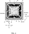
FIG. 2 is a plan view schematically showing a blow-out panel and a central member of the air conditioning indoor unit. -
FIG. 3 is a plan view schematically showing local structures of a blow-out panel and a central member of the air conditioning indoor unit. -
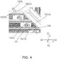
FIG. 4 is a plan view schematically showing a local structure of the blow-out panel of the air conditioning indoor unit, and showing a structure near a first link. -
FIG. 5 is a plan view schematically showing a local structure of the blow-out panel of the air conditioning indoor unit, and showing a structure near a second link. -
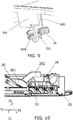
FIG. 6 is a perspective view schematically showing a local structure of the blow-out panel of the air conditioning indoor unit, in which guide vanes are not shown. -
FIG. 7 is a perspective view schematically showing a connection structure of the guide vanes on the blow-out panel of the air conditioning indoor unit, where part of the guide vanes is not shown (here, the guide vanes are in an open state). -
FIG. 8 is a perspective view schematically showing a local structure of the blow-out panel of the air conditioning indoor unit. -
FIG. 9 is a perspective view schematically showing the connection structure of the guide vanes in the blow-out panel of the air conditioning indoor unit, of which the guide vanes are not shown. -
FIG. 10 is a sectional side view schematically showing a local structure of the air conditioning indoor unit. - An embodiment will be described below with reference to
FIGS. 1 to 10 by taking an air conditioning indoor unit provided with an indoor unit body and a blow-out panel as an example in accordance with an actual installation state. - Here, for convenience of description, three directions orthogonal to one another are set to X direction, Y direction, and Z direction. Among them, the X direction and the Y direction correspond to directions in a horizontal plane when the air conditioning indoor unit is actually installed. The Z direction corresponds to a vertical direction when the air conditioning indoor unit is actually installed. Y1 direction side, Y2 direction side, X1 direction side, X2 direction side, Z1 direction side, and Z2 direction side respectively correspond to a front side, a rear side, a left side, a right side, a lower side, and an upper side when the air conditioning indoor unit is actually installed.
- As shown in
FIG. 1 , the air conditioningindoor unit 1 includes anindoor unit body 10 in which anaxial fan 30 is provided, and a blow-outpanel 20 connected to the indoor unit body 10 (in the illustrated example, the blow-outpanel 20 is provided at a lower part of theindoor unit body 10.) - Here, the
indoor unit body 10 has a substantially rectangular parallelepiped shape as a whole, and has an upper surface, a bottom surface, and four side surfaces. An intake port JF is provided on each side face, and afilter component 40 is provided at each intake port JP. As shown inFIG. 1 , aheat exchanger 50 is further provided inside theindoor unit body 10. Theheat exchanger 50 is provided at an inner side of the intake port JF and is surrounded by thefilter component 40. Theaxial fan 30 is provided at an inner side of theheat exchanger 50. Theaxial fan 30 is provided such that an axis line overlaps with a center axis line L of the blow-out panel 20 (that is, an axis line extending through a center of the blow-outpanel 20 along a thickness direction of the blow-out panel 20). - Further, as shown in
FIGS. 1 and2 , the blow-outpanel 20 has anouter frame 21 and aninner frame 22. Theouter frame 21 and theinner frame 22 surround a polygonal blow-out port CF.Guide vanes 23 are provided in the blow-out port CF. The blow-outpanel 20 is provided with alink 24. Thelink 24 deviates from a corner of the blow-out port CF (that is, thelink 24 does not pass through an apex of the corner of the blow-out port CF) and extends from the central direction of the blow-outpanel 20 to the corner of the blow-out port CF. The guide vanes 23 are rotatably attached to thelink 24. - Here, as shown in
FIGS. 1 and2 , as viewed from an inner surface side to an outer surface side of the blow-outpanel 20, specifically, as viewed from a side of the blow-outpanel 20 closer to the indoor unit body 10 (Z2 direction side) toward a side away from the indoor unit body 10 (Z1 direction side), thelink 24 has a first surface (downstream in a clockwise direction inFIG. 2 ) and a second surface (upstream in the clockwise direction inFIG. 2 ). An airflow generated by the axial fan or the like flows through the second surface and the first surface in that order. That is, the second surface is a windward surface and the first surface is a leeward surface. - Here, as shown in
FIG. 2 , the blow-outpanel 20 has a substantially rectangular shape, and has the rectangularouter frame 21 and the rectangularinner frame 22. Theouter frame 21 and theinner frame 22 surround the rectangular blow-out port CF. A set ofguide vanes 23 is provided on each side of the blow-out port CF (each side configures an auxiliary blow-out port). As shown inFIGS. 2 and3 , each set ofguide vanes 23 is a combination of three parallel guide vanes. Lengths of the three parallel guide vanes is set to increase toward a direction from theinner frame 22 to theouter frame 21 of the blow-outpanel 20. When theguide vanes 23 rotate to open the blow-out port CF, the airflow at both ends of theguide vanes 23 gradually spreads downward along the ends of theguide vanes 23, and is not blown out in parallel. Thus, the airflow having a relatively low flow velocity at both ends of the guide vanes 23 is not adhered to a ceiling. This prevents contaminants such as dust trapped in the airflow from adhering to the ceiling. As a whole, most of the airflow is still guided by theguide vanes 23, and a uniform distribution of the airflow can be still maintained. - Further, as shown in
FIG. 2 , thelink 24 connects theouter frame 21 and theinner frame 22, and is provided near an angle bisector of the corner of the blow-out port CF (in the illustrated example, thelink 24 is parallel to the angle bisector of the corner of the blow-out port CF). Thelink 24 includes afirst link 24A and asecond link 24B provided on one side of the blow-out port. As viewed along the Z direction (specifically, as viewed from a viewpoint ofFIG. 2 ), a vertical line CX passing through the center of the blow-outpanel 20 on one side of the blow-out port CF is disposed downstream of thefirst link 24A in a clockwise direction around the center of the blow-out panel. Thesecond link 24B is disposed downstream of the vertical line CX in the clockwise direction around the center of the blow-out panel. Thus, by using thefirst link 24A and thesecond link 24B, respectively, the airflow generated by the axial fan or the like can be guided to the two corners of the blow-out port CF, and the airflows at the two corners of the blow-out port CF are both in a state close to a uniform distribution. - Further, as shown in
FIGS. 1 to 3 , acentral member 26 is provided at a lower part of theaxial fan 30 and at a lower part of the blow-out panel 20 (in the illustrated example, thecentral member 26 projects toward theaxial fan 30. However, the shape is not limited to this, and may be appropriately changed as necessary). Thecentral member 26 is provided with anair guide piece 261. An end point of a suction end of theair guide piece 261 is disposed on an extension line of a link body of thelink 24. - Further, as shown in
FIG. 2 , theair guide piece 261 has an arc shape as viewed in the Z direction. Theair guide piece 261 has a firstair guide piece 261A and a secondair guide piece 261B. As viewed along the Z direction (specifically, as viewed from the viewpoint ofFIG. 2 ), the firstair guide piece 261A is disposed upstream of the secondair guide piece 261B in the clockwise direction around the center of the blow-out panel. - Here, as shown in
FIG. 2 , onefirst link 24A and onesecond link 24B are provided on one side of the blow-out port CF. Further, one firstair guide piece 261A and one secondair guide piece 261B are provided. - As shown in
FIGS. 2 and4 , thefirst link 24A includes alink body 241A on which eachguide vane 23 is rotatably arranged, and a connectingportion 242A. The connectingportion 242A is disposed closer to the central direction of the blow-outpanel 20 than thelink body 241A, and connects thelink body 241A and theinner frame 22. Further, as viewed along the Z direction, asecond surface 2421A of the connectingportion 242A forms an inwardly concave shape together with asecond surface 2411A of thelink body 241A. Here, as shown inFIGS. 6 and8 , the connectingportion 242A connects afirst portion 2423A that extends substantially along a direction in which thelink body 241A extends and asecond portion 2424A that connects thefirst portion 2423A to theinner frame 22. The first portion and the second portion both have a guide surface that has an effect of guiding. Specifically, end surfaces of thefirst portion 2423A and thesecond portion 2424A close to the central direction of the blow-out panel are both arc-shaped guide surfaces. Further, the end surface of thesecond portion 2424A away from the central direction of the blow-out panel is a chamfered surface extending toward the corners of the blow-out port CF (that is, as the end surface goes closer to the corners of the blow-out port CF, the windward surface and the leeward surface come closer.) The chamfered surface guides the airflow generated by the axial fan or the like to the corners of the blow-out port CF. - As shown in
FIGS. 2 and5 , thesecond link 24B includes alink body 241B on which eachguide vane 23 is rotatably arranged, and a connectingportion 242B. The connectingportion 242B is disposed closer to the central direction of the blow-outpanel 20 than thelink body 241B, and connects thelink body 241B and theinner frame 22. Further, as viewed along the Z direction, asecond surface 2421B of the connectingportion 242B forms an inwardly concave shape together with asecond surface 2411B of thelink body 241B. Similarly, as shown inFIG. 8 , the connectingportion 242B connects afirst portion 2423B that extends substantially along a direction in which thelink body 241B extends and asecond portion 2424B that connects thefirst portion 2423B to theinner frame 22. The first portion and the second portion both have a guide surface that has an effect of guiding. Specifically, end surfaces of thefirst portion 2423B and thesecond portion 2424B close to the central direction of the blow-out panel are both arc-shaped guide surfaces. The end surface of thesecond portion 2424B away from the central direction of the blow-out panel is a chamfered surface extending toward the corners of the blow-out port CF. The chamfered surface guides the airflow generated by the axial fan or the like to the corners of the blow-out port CF. - Here, as shown in
FIG. 4 , on thefirst link 24A, the windward surface as thesecond surface 2411A of thelink body 241A and the leeward surface as afirst surface 2412A are substantially flat surfaces. Thesecond surface 2421A and afirst surface 2422A of the connectingportion 242A are substantially flat surfaces. Thesecond surface 2411A of thelink body 241A intersects with thesecond surface 2421A of the connectingportion 242A. Thefirst surface 2412A of thelink body 241A is substantially flush with thefirst surface 2422A of the connectingportion 242A or forms an obtuse angle larger than an angle formed by the second surfaces. Thus, the airflow guided from the air guide piece can be guided to thelink body 2412A along thefirst surface 2422A of the connectingportion 242A and further to the corners of the blow-out port CF. Similarly, as shown inFIG. 5 , on thesecond link 24B, the windward surface as thesecond surface 2411B and the leeward surface as afirst surface 2412B of thelink body 241B are substantially flat surfaces. Thesecond surface 2421B and afirst surface 2422B of the connectingportion 242B are substantially flat surfaces. Thesecond surface 2411B of thelink body 241B intersects with thesecond surface 2421B of the connectingportion 242B. Thefirst surface 2412B of thelink body 241B is substantially flush with thefirst surface 2422B of the connectingportion 242B or forms an obtuse angle larger than an angle formed by the windward surfaces. Thus, the airflow guided from the air guide piece can be guided to thelink body 2412B along thefirst surface 2422B of the connectingportion 242B and further to the corners of the blow-out port CF. - Furthermore, as shown in
FIGS. 4 and5 , on thefirst link 24A, thesecond surface 2421A of the connectingportion 242A forms an obtuse angle with thesecond surface 2411A of thelink body 241A. Further, on thesecond link 24B, thesecond surface 2421B of the connectingportion 242B forms an obtuse angle with thesecond surface 2411B of thelink body 241B. Thus, when the airflow generated by the axial fan or the like flows to thelink bodies portions second surfaces portions second surfaces link bodies - Further, as shown in
FIGS. 6 to 9 , on thefirst link 24A, a rotatingshaft 29 of eachguide vane 23 is pivotally connected to thelink body 241A in a substantially horizontal state. Specifically, eachguide vane 23 includes anelongated vane body 231 and afixing piece 232. The fixingpiece 232 is perpendicular to thevane body 231, and is connected to a first end of therotating shaft 29. Thefirst link 24A has a projectingpiece 243 that intersects with a longitudinal direction of thefirst link 24A and projects. The projectingpiece 243 configures a support that supports therotating shaft 29. A second end of therotating shaft 29 is pivotally connected to the projectingpiece 243. In the illustrated example, the projectingpiece 243 is provided on thelink body 241A, and is closer to the corners of the blow-out port CF than the fixingpiece 232. A boundary between the connectingportion 242A and thelink body 241A is disposed between theinner frame 22 and therotating shaft 29, and thus theguide vanes 23 are stably rotated. The projectingpiece 243 includes afirst portion 2431 extending from thelink body 241A along the thickness direction of the blow-outpanel 20 and asecond portion 2432. Thesecond portion 2432 extends at an angle with respect to thefirst portion 2431 and is parallel to the fixingpiece 232. The second end of therotating shaft 29 is pivotally connected to thesecond portion 2432. - Similarly, as shown in
FIGS. 6 to 9 , on thesecond link 24B, the rotating shaft of eachguide vane 23 is pivotally connected to thelink body 241B in a substantially horizontal state. Specifically, eachguide vane 23 includes thevane body 231 having an elongated shape and the fixingpiece 232. The fixingpiece 232 is perpendicular to thevane body 231, and is connected to the first end of therotating shaft 29. Thesecond link 24B has the projectingpiece 243 that projects to intersect with the longitudinal direction of thesecond link 24B. The projectingpiece 243 configures a support that supports therotating shaft 29. A second end of therotating shaft 29 is pivotally connected to the projectingpiece 243. In the illustrated example, the projectingpiece 243 is provided on thelink body 241B, and is closer to the corners of the blow-out port CF than the fixingpiece 232. A boundary between the connectingportion 242B and thelink body 241B is disposed between theinner frame 22 and therotating shaft 29, and thus theguide vanes 23 are stably rotated. The projectingpiece 243 includes thefirst portion 2431 extending from thelink body 241B along the thickness direction of the blow-outpanel 20 and thesecond portion 2432. Thesecond portion 2432 extends at an angle with respect to thefirst portion 2431 and is parallel to the fixingpiece 232. The second end of therotating shaft 29 is pivotally connected to thesecond portion 2432. - Furthermore, as shown in
FIGS. 7 and9 , abuffer ring 291 is integrally formed on therotating shaft 29. Thebuffer ring 291 is disposed between the fixingpiece 232 and the projectingpiece 243 with eachguide vane 23 attached. Thebuffer ring 291 prevents a jammed pivotal rotation of the guide vanes or accelerated wear of the fixing piece due to friction between the fixingpiece 232 and the projectingpiece 243. Here, the second end of therotating shaft 29, which has a hollow structure and is divided into four pieces, can form a space for elastic deformation, and makes it convenient for theguide vanes 23 to be attached and detached. The first end of therotating shaft 29 may be integrally molded with the fixingpiece 232 or may be fixed and bonded to the fixingpiece 232. - Further, as shown in
FIGS. 2 ,6 and7 , each projectingpiece 243 provided on thefirst link 24A and thesecond link 24B is pivotally connected via the rotatingshaft 29 to each end of thesame guide vane 23 in the longitudinal direction. The guide vanes 23 thus rotate stably. The projectingpieces 243 provided on thefirst link 24A and thesecond link 24B are provided at positions closer to the corners of the blow-out port CF than the fixingpieces 232 provided on both ends of the guide vanes. That is, the fixingpieces 232 at both ends of theguide vanes 23 are provided on different sides of thefirst link 24A and thesecond link 24B, respectively. Thus, as compared with the case where the fixingpieces 232 are provided on the same side of thefirst link 24A and thesecond link 24B, the rotatingshaft 29 is prevented from falling off the projectingpiece 243. - Further, as shown in
FIG. 2 , thefirst link 24A and thesecond link 24B on both sides of one corner of the blow-out port CF are formed such that the link body of thefirst link 24A is parallel to the link body of thesecond link 24B. - Further, as shown in
FIG. 2 andFIG. 3 , the suction end of theair guide piece 261 is disposed on the extension line of the first surface of the link body of thelink 24, and the blow-out end of theair guide piece 261 is closer to the vertical line CX than thelink 24. Specifically, a suction end 261AA of the firstair guide piece 261A is disposed on an extension line YC1 of thefirst surface 2412A of thelink body 241A of thefirst link 24A. A suction end 261AB of the secondair guide piece 261B is disposed on an extension line YC2 of thefirst surface 2412B of thelink body 241B of thesecond link 24B. A blow-out end 261BA of the firstair guide piece 261A is closer to the vertical line CX than thefirst link 24A. A blow-out end 261BB of the secondair guide piece 261B is closer to the vertical line CX than thesecond link 24B. Then, a point X farthest from the vertical line CX on the leeward surface of the secondair guide piece 261B is disposed on an extension line YC3 of thesecond surface 2421B of the connectingportion 242B of thesecond link 24B. Thus, the airflow guided from the leeward surface of the suction end of the secondair guide piece 261B flows to the corners of the blow-out panel CF along the first surface of thesecond link 241B. Further, the airflow guided from the leeward surface of the blow-out end of the secondair guide piece 261B flows to thesecond surface 2421B of the connectingportion 242B of thesecond link 241B. - Here, as shown in
FIGS. 2 and3 , the blow-outpanel 20 is further provided with anintermediate link 25. Theintermediate link 25 connects theouter frame 21 and theinner frame 22. As viewed along the Z direction, theintermediate link 25 is disposed at a middle of the blow-out port CF and is perpendicular to the guide vanes 23. A stepping motor (not shown) that drives the rotation of the guide vanes 23 is attached to theintermediate link 25. Thefirst link 24A and thesecond link 24B are provided substantially symmetrically with respect to theintermediate link 25. - Here, as shown in
FIG. 10 , during an operation of the air conditioningindoor unit 1, theguide vanes 23 are reversed to a predetermined angle with respect to the outer surface of the blow-outpanel 20. There is a gap between (an uppermost edge of) theguide vanes 23 and (the link body of) thelink 24 for the airflow generated by the axial fan or the like to flow in the thickness direction of the blow-out panel. A gap of about 5 mm is preferably ensured between (the uppermost edge of) theguide vanes 23 and (the link body of) thelink 24 even when theguide vanes 23 are reversed to a maximum angle (for example, 75° or 90°) with respect to the outer surface of the blow-outpanel 20. This gap may be longer than 5 mm, provided that the gap does not affect a miniaturization of the blow-out panel in order to expand a path through which the airflow flows. Then, in order to ensure that theguide vanes 23 do not interfere with the link when theguide vanes 23 are reversed, the gap may be shorter than 5 mm. - Further, as shown in
FIG. 10 , theair guide piece 261 at least partially overlaps with thelink 24 as viewed in a horizontal direction. Here, in the Z direction, thelink 24 is disposed in the center of theair guide piece 261. The airflow generated by the axial fan or the like flows to the connecting portion of thelink 24 via the windward surface of theair guide piece 261, and is guided to the corners of the blow-out port CF along the link body. - Then, as shown in
FIG. 10 , at least part of thecentral member 26 projects from the blow-outpanel 20 in the Z direction. Theair guide piece 261 can be thus easily provided on thecentral member 26. Further, thecentral member 26, which has the arc-shaped air guide surface, allows the airflow generated by the axial fan or the like to be guided to the blow-out port CF. - Further, as shown in
FIGS. 1 and10 , the air conditioningindoor unit 1 further includes aside frame member 28 surrounding theaxial fan 30. Thecentral member 26 has asupport rod 262, and is connected to theside frame member 28 via thesupport rod 262. Then, as shown inFIGS. 2 and3 , thesupport rod 262 is disposed between theair guide piece 261 and thelink 24 as viewed along the Z direction. As shown inFIG. 10 , as viewed along the horizontal direction, at least a part of theair guide piece 261 is arranged to be shifted from the support rod 262 (in the illustrated example, thesupport rod 262 extends upward from a position of theair guide piece 261 to the outside in a radial direction). One side of thesupport rod 262 facing theaxial fan 30 is an arc-shaped surface, and thus the airflow can be guided while the interference with the airflow generated by the axial fan or the like is reduced. - Further, as shown in
FIG. 2 , the blow-outpanel 20 is further provided with aweather strip 27. Theweather strip 27 is provided at each corner of the blow-out port CF, and connects theouter frame 21 and theinner frame 22. The weather strip is used to separate the airflows guided by the guide vanes adjacent in a peripheral direction, and thus the airflows guided by the guide vanes adjacent in the peripheral direction from interfering with each other at the blow-out port. Further, the airflow at the blow-out port can be improved. - In this embodiment, during the operation of the
axial fan 30 of the air conditioningindoor unit 1, the airflow is sucked into theindoor unit body 10 from the suction port JP by an action of theaxial fan 30, flows through thefilter component 40 and theheat exchanger 50 in that order, and flows to a center of the air conditioningindoor unit 1. Then, the airflow flows through theaxial fan 30 to form a spiral airflow, and flows down below to thecentral member 26. After that, the airflow is guided by the arc-shaped air guide surface of thecentral member 26, spreads from the center of the blow-outpanel 20 all around to the blow-out port CF. A part of the airflow is guided to the corners of the blow-out port CF by theair guide piece 261 provided on thecentral member 26. This airflow flows from below thesupport rod 262 and is guided to the corners of the blow-out port CF via thelink 24. Finally, the airflow flows through the blow-out port CF. The guide vanes 23 provided at the blow-out port CF are driven by the motor to be reversed to a predetermined angle and guide the airflow to the outside of the air conditioningindoor unit 1. - In the air conditioning
indoor unit 1 according to this embodiment, on the blow-outpanel 20, the polygonal blow-out port CF is surrounded by theouter frame 21 and theinner frame 22. This enables the air to be blown out all around 360°. Thelink 24 to which theguide vanes 23 are attached extends from the central direction of the blow-outpanel 20 to the corners of the blow-out port CF, the airflow blown out from theaxial fan 30 easily flows along thelink 24 to the corners of the blow-out port CF. This allows the air to be blown out of the blow-out port CF close to uniformly. - Further, the rotating
shaft 29 of eachguide vane 23 is pivotally connected to thelink 24, and thus a connection structure between theguide vanes 23 and thelink 24 is simple. This avoids the interference of the guide vanes with the link when the guide vanes are rotated. This facilitates connection of the guide vanes to the link. - Further, in the air conditioning
indoor unit 1 according to this embodiment, thelink 24 connects theouter frame 21 and theinner frame 22, and thus a strength of the blow-outpanel 20 as a whole is increased. - Further, in the air conditioning
indoor unit 1 according to this embodiment, thelink 24 is provided near the angle bisector of each corner of the blow-out port CF. Specifically, thelink 24 is provided to be parallel to the angle bisector of each corner of the blow-out port CF. This allows the airflow blown out from theaxial fan 30 to further easily flow along thelink 24 to the corners of the blow-out port CF, and allows the air to be blown out of the blow-out port CF close to uniformly. - Further, in the air conditioning
indoor unit 1 according to this embodiment, one end of the connecting portion of thelink 24 away from the link body is arc-shaped as viewed along the Z direction. Thus, it is possible to reduce the interference of the one end of the connecting portion of thelink 24 away from the link body with the airflow generated by theaxial fan 30. The end, which is arc-shaped, can guide the airflow generated by the axial fan or the like to the corners of the blow-out port CF. This allows the air to be blown out of the blow-out port CF close to uniformly. - Further, in the air conditioning
indoor unit 1 according to this embodiment, a width of the connecting portion of thelink 24 gradually narrows toward one side of the link body as viewed along the Z direction. Thus, the strength of theentire link 24 is ensured, and a volume of thelink 24 can be also reduced. This helps reduce the interference of the connecting portion of thelink 24 with the airflow generated by theaxial fan 24, and allows the air to be blown out of the blow-out port CF uniformly. - Further, in the air conditioning
indoor unit 1 according to this embodiment, as viewed along the Z direction, the second surface of the connecting portion of thelink 24 forms an inwardly concave shape together with the second surface of the link body. Thus, by using the second surface of the connecting portion of thelink 24, the airflow generated by theaxial fan 30 is easily guided to the corners of the blow-out port CF via the second surface of the link body. This also allows the airflow to be blown out from the corners of the blow-out port, and further allows the air to be blown out close to around 360° of the blow-out panel. - Further, in the air conditioning
indoor unit 1 according to this embodiment, the second surface of the connecting portion of thelink 24 and the second surface of the link body form an obtuse angle. It is therefore possible to ensure an effect that the airflow generated by theaxial fan 30 is guided by using the second surface of the connecting portion of thelink 24. Further, it is possible to reduce the interference of the connecting portion of thelink 24 and the link body with the airflow generated by theaxial fan 30. This allows the air to be blown out of the blow-out port CF close to uniformly. - Further, in the air conditioning
indoor unit 1 according to this embodiment, thefirst link 24A and thesecond link 24B on both sides of one corner of the blow-out port CF are formed such that thelink body 241A of thefirst link 24A is parallel to thelink body 241B of thesecond link 24B. This can simplify an entire structure of the blow-outpanel 20, and reduce the interference of the link body of thelink 24 with the airflow at the corners of the blow-out port CF. This allows the air to be blown out of the blow-out port CF close to uniformly. - Further, in the air conditioning
indoor unit 1 according to this embodiment, the stepping motor that drives the rotation of the guide vanes 23 is attached to theintermediate link 25. Thus, a force applied to the guide vanes 23 becomes close to uniform, and a drive structure can be simplified. Further, the stepping motor, which is provided on the outer frame of the blow-out port, is also advantageous for miniaturization of the blow-out panel. - In the air conditioning
indoor unit 1 according to this embodiment, thecentral member 26 is provided at a center of theinner frame 22. Thecentral member 26 is provided with theair guide piece 261. As a result, the airflow generated by theaxial fan 30 is guided by using theair guide piece 261, and the airflow is thus prevented from being directly blown downward. This allows the air to be blown out of the blow-out port CF close to uniformly. - Further, in the air conditioning
indoor unit 1 according to this embodiment, the suction end of theair guide piece 261 is disposed on the extension line of the first surface of the link body of thelink 24. This can further ensure the airflow flowing to the corners of the blow-out port CF, and allows the air to be blown out of the blow-out port CF close to uniformly, and allows the air to be blown out around 360° of the blow-out panel. - Further, in the air conditioning
indoor unit 1 according to this embodiment, thelink 24 is disposed at the center of theair guide piece 261 in the Z direction. This strengthens an interaction between theair guide piece 261 and thelink 24, ensures the airflow flowing to the corners of the blow-out port CF, and allows the air to be blown out of the blow-out port CF close to uniformly. - Although the blow-out panel and the air conditioning indoor unit have been described above as an example with reference to the drawings, the specific implementation of the blow-out panel and the air conditioning indoor unit is not limited by the above embodiment.
- For example, in the above embodiment, the air conditioning indoor unit including the indoor unit body and the blow-out panel provided at the lower part of the indoor unit body has been described as an example. However, the present invention is not limited thereto. The present invention may have a configuration where the blow-out panel is connected to an air treatment device via a duct, and the spiral airflow discharged from a fan component in the air treatment device is sent to the blow-out panel via the duct and further discharged from the blow-out panel. The blow-out panel and the air conditioning indoor unit may be configured as such.
- Further, in the above embodiment, the
indoor unit body 10 has a substantially rectangular parallelepiped shape as a whole, but the shape of the indoor unit body may be appropriately changed depending on the situation. For example, the indoor unit body may be formed in a substantially columnar shape, a prismatic shape other than a square prism, or the like. Similarly, the blow-outpanel 20 is substantially rectangular as viewed from the Z direction in the above embodiment, but the shape of the blow-out panel may be appropriately changed depending on the situation. For example, the blow-out panel may have a substantially circular shape as viewed from the Z direction, or may have a shape such as a polygon other than a quadrangle as viewed from the Z direction. - Further, the blow-out port CF is rectangular in the above embodiment, but the present invention is not limited to this, and the blow-out port may be formed in a polygonal shape.
- Further, the suction port JF is provided on each side surface of the
indoor unit body 10, and thefilter component 40 is provided at each suction port JF in the above embodiment. The number of suction ports and the number of filter components may be adjusted as necessary. - Further, in the above embodiment, on one side of the blow-out port CF, one
first link 24A and onesecond link 24B are provided, and one firstair guide piece 261A and one secondair guide piece 261B are provided. However, in this case as well, the number of thefirst link 24A, thesecond link 24B, the firstair guide piece 261A, and the secondair guide piece 261B provided on one side of the blow-out port CF may be changed as necessary. - Further, in the above embodiment, the
link 24 connects theouter frame 21 and theinner frame 22. However, without being limited to such a configuration, thelink 24 may be connected to only one of theouter frame 21 or theinner frame 22. - In the above embodiment, the
link 24 includes thefirst link 24A and thesecond link 24B. However, the present invention is not limited thereto, and thelink 24 may include only one of thefirst link 24A or thesecond link 24B. Similarly, theair guide piece 261 includes the firstair guide piece 261A and the secondair guide piece 261B in the above embodiment, but the present invention is not limited thereto. Theair guide piece 261 may include only one of the firstair guide piece 261A or the secondair guide piece 261B. - Further, in the above embodiment, on the
first link 24A, thesecond surface 2411A and thefirst surface 2412A of thelink body 241A are substantially flat surfaces, and thesecond surface 2421A and thefirst surface 2422A of the connectingportion 242A are substantially flat surfaces. On thesecond link 24B, thesecond surface 2411B and thefirst surface 2412B of thelink body 241B are substantially flat surfaces, and thesecond surface 2421B and thefirst surface 2422B of the connectingportion 242B are substantially flat surfaces. However, the present invention is not limited thereto, and thesecond surface 2411A and thefirst surface 2412A of thelink body 241A, and thesecond surface 2421A and thefirst surface 2422A of the connectingportion 242A may be formed in other shapes. (For example, the surfaces may be formed in an arc shape or a polygonal line shape as viewed from the Z direction.) Further, thesecond surface 2411B and thefirst surface 2412B of thelink body 241B, and thesecond surface 2421B and thefirst surface 2422B of the connectingportion 242B may be formed in other shapes (for example, the surfaces may be formed in an arc shape or a polygonal line shape as viewed from the Z direction). - Further, in the above embodiment, the
first link 24A and thesecond link 24B on both sides of one corner of the blow-out port CF are formed such that the link body of thefirst link 24A is parallel to the link body of thesecond link 24B. However, the present invention is not limited thereto, and the link body of thefirst link 24A and the link body of thesecond link 24B may be formed to be unparallel to each other. - Further, in the above embodiment, the
air guide piece 261 has an arc shape as viewed from the Z direction. However, the shape of the air guide piece is not limited thereto, and may be appropriately changed as necessary. - Further, in the above embodiment, the suction end of the
air guide piece 261 is disposed on the extension line of the first surface of the link body of thelink 24. However, the present invention is not limited thereto, and the suction end of the air guide piece may be disposed substantially in the direction in which the link body of the link extends. - Further, in the above embodiment, the specific form of the
rotating shaft 29 may be appropriately changed as necessary. For example, the rotatingshaft 29 may be a simple rod-shaped or tubular member or a joint. -
- 1
- Air conditioning indoor unit
- 10
- Indoor unit body
- 20
- Blow-out panel
- 21
- Outer frame
- 22
- Inner frame
- 23
- Guide vane
- 231
- Vane body
- 232
- Fixing piece
- 24
- Link
- 24A
- First link
- 24B
- Second link
- 241A
- Link body
- 241B
- Link body
- 2411A
- Second surface
- 2411B
- Second surface
- 2412A
- First surface
- 2412B
- First surface
- 242A
- Connecting portion
- 242B
- Connecting portion
- 2421A
- Second surface
- 2421B
- Second surface
- 2422A
- First surface
- 2422B
- First surface
- 2423A
- First portion of connecting portion
- 2423B
- First portion of connecting portion
- 2424A
- Second portion of connecting portion
- 2424B
- Second portion of connecting portion
- XMA
- Chamfered surface
- XMB
- Chamfered surface
- 243
- Projecting piece
- 2431
- First portion of projecting piece
- 2432
- Second portion of projecting piece
- 25
- Intermediate link
- 26
- Central member
- 261
- Air guide piece
- 261A
- First air guide piece
- 261B
- Second air guide piece
- 262
- Support rod
- 27
- Side frame member
- 29
- Rotating shaft
- 291
- Buffer ring
- 30
- Axial fan
- 40
- Filter component
- 50
- Heat exchanger
- L
- Center axis line
- CX
- Vertical line
- YC1
- Extension line
- YC2
- Extension line
- YC3
- Extension line
Claims (14)
- A blow-out panel (20) comprising:an outer frame (21);an inner frame (22);a guide vane (23); anda link (24), whereinthe outer frame (21) and the inner frame (22) surround a blow-out port (CF) having a polygonal shape,the guide vane (23) is provided in the blow-out port (CF),the link (24) deviates from a corner of the blow-out port (CF) and extends from a central direction of the blow-out panel (20) to the corner of the blow-out port (CF), anda rotating shaft (29) of the guide vane (23) is pivotally connected to the link (24) in parallel to a longitudinal direction of the guide vane.
- The blow-out panel according to claim 1, wherein the link (24) connects the outer frame (21) and the inner frame (22).
- The blow-out panel according to claim 1 or 2, wherein the link (24) is provided near an angle bisector of the corner of the blow-out port (CF).
- The blow-out panel according to any one of claims 1 to 3, whereinthe guide vane (23) has a vane body (231) having an elongated shape, and a fixing piece (232) that is perpendicular to the vane body and to which a first end of the rotating shaft (29) is connected,the link (24) has a projecting piece (243) that intersects with a longitudinal direction of the link and projects, anda second end of the rotating shaft (29) is pivotally connected to the projecting piece.
- The blow-out panel according to claim 4, whereinthe link (24) includes a link body (241A, 241B) and a connecting portion (242A, 242B), whereinthe connecting portion (242A, 242B) is disposed closer to a center of the blow-out panel (20) than the link body (241A, 241B), and connects the link body (241A, 241B) and the inner frame (22), andthe projecting piece is provided on the link body (241A, 241B).
- The blow-out panel according to claim 5, whereinthe projecting piece (243) has a first portion (2431) that extends along a thickness direction of the blow-out panel from the link body (241A, 241B), and a second portion (2432) that extends at an angle with the first portion and is parallel to the fixing piece (232), anda second end of the rotating shaft (29) is pivotally connected to the second portion.
- The blow-out panel according to any one of claims 4 to 6, wherein the projecting piece (243) is closer to a corner of the blow-out port (CF) than the fixing piece (232).
- The blow-out panel according to any one of claims 1 to 7, whereinthe link (24) has a first link (24A) and a second link (24B) provided on one side of the blow-out port (CF),the second link (24B) is disposed downstream of the first link (24A) in a clockwise direction around the center of the blow-out panel as viewed from an inner surface side to an outer surface side of the blow-out panel, andthe guide vane (23) is provided with a first rotating shaft (29A) and a second rotating shaft (29B) that are pivotally connected to the first link (24A) and the second link (24B), respectively.
- The blow-out panel according to claim 8, further comprising an intermediate link (25), whereinthe guide vane (23) is provided with an intermediate rotating shaft pivotally connected to the intermediate link (25),as viewed from a thickness direction of the blow-out panel (20), the intermediate link (25) is disposed in a middle of the blow-out port (CF), and is perpendicular to the guide vane (23), anda stepping motor that drives a rotation of the guide vane (23) is attached to the intermediate link (25).
- The blow-out panel according to any one of claims 1 to 7, whereinthe link (24) has a link body (241A, 241B) and a connecting portion (242A, 242B),the connecting portion (242A, 242B) is disposed closer to the center of the blow-out panel (20) than the link body (241A, 241B), and connects the link body (241A, 241B) and the inner frame (22),the connecting portion (242A, 242B) and the link body (241A, 241B) each have a first surface and a second surface,as viewed from the inner surface side to the outer surface side of the blow-out panel, the first surface is disposed downstream of the second surface in the clockwise direction around the center of the blow-out panel, andthe second surface (2421A, 2421B) of the connecting portion (242A, 242B) forms an inwardly concave shape together with the second surface (2411A, 2411B) of the link body (241A, 241B).
- The blow-out panel according to any one of claims 1 to 7, whereinthe link (24) has a first link (24A) and a second link (24B) that are provided on one side of the blow-out port (CF),the second link (24B) is disposed downstream of the first link (24A) in a clockwise direction around a center of the blow-out panel as viewed from an inner surface side to an outer surface side of the blow-out panel, andthe first link (24A) and the second link (24B) on both sides of one corner of the blow-out port (CF) are formed such that the link body (241A) of the first link (24A) is in parallel to the link body (241B) of the second link (24B).
- The blow-out panel according to any one of claims 1 to 11, wherein a central member (26) provided with an air guide piece (261) is installed at a center of the inner frame (22).
- The blow-out panel according to claim 12, whereinthe link (24) has a link body (241A, 241B) and a connecting portion (242A, 242B),the connecting portion (242A, 242B) is disposed closer to a center of the blow-out panel (20) than the link body (241A, 241B), and connects the link body (241A, 241B) and the inner frame (22),the link body (241A, 241B) has a first surface and a second surface,the first surface is disposed downstream of the second surface around the center of the blow-out panel in a clockwise direction as viewed from an inner surface side to an outer surface side of the blow-out panel (20), anda suction end (261A) of the air guide piece (261) is disposed on an extension line of the first surface (2412A, 2412B) of the link body (241A, 241B).
- An air conditioning indoor unit comprising:an indoor unit body (10); andthe blow-out panel (20) described in any one of claims 1 to 13, whereinthe blow-out panel (20) is directly connected to the indoor unit body (10), or connected to the indoor unit body (10) via a duct.
Applications Claiming Priority (2)
| Application Number | Priority Date | Filing Date | Title |
|---|---|---|---|
| CN201711409126.4A CN109959142B (en) | 2017-12-22 | 2017-12-22 | Air outlet panel and air conditioner indoor unit |
| PCT/JP2018/042001 WO2019123894A1 (en) | 2017-12-22 | 2018-11-13 | Blow-out panel, and air conditioning indoor unit |
Publications (3)
| Publication Number | Publication Date |
|---|---|
| EP3730860A1 true EP3730860A1 (en) | 2020-10-28 |
| EP3730860A4 EP3730860A4 (en) | 2021-02-10 |
| EP3730860B1 EP3730860B1 (en) | 2022-03-23 |
Family
ID=66994031
Family Applications (1)
| Application Number | Title | Priority Date | Filing Date |
|---|---|---|---|
| EP18891973.2A Active EP3730860B1 (en) | 2017-12-22 | 2018-11-13 | Blow-out panel, and air conditioning indoor unit |
Country Status (4)
| Country | Link |
|---|---|
| EP (1) | EP3730860B1 (en) |
| JP (1) | JP6835259B2 (en) |
| CN (1) | CN109959142B (en) |
| WO (1) | WO2019123894A1 (en) |
Families Citing this family (1)
| Publication number | Priority date | Publication date | Assignee | Title |
|---|---|---|---|---|
| CN111912000B (en) * | 2020-05-22 | 2023-12-26 | 海信空调有限公司 | Indoor air conditioner |
Family Cites Families (15)
| Publication number | Priority date | Publication date | Assignee | Title |
|---|---|---|---|---|
| JPS5426860U (en) * | 1977-07-26 | 1979-02-21 | ||
| JPH086186Y2 (en) * | 1990-02-13 | 1996-02-21 | 三菱重工業株式会社 | Air conditioner |
| JPH0914742A (en) * | 1995-06-29 | 1997-01-17 | Mitsubishi Heavy Ind Ltd | Air conditioner |
| JP3885846B2 (en) * | 1998-04-17 | 2007-02-28 | 株式会社富士通ゼネラル | Air conditioner |
| AU2003280658A1 (en) * | 2002-10-31 | 2004-05-25 | Daikin Industries, Ltd. | Indoor apparatus for air conditioner |
| JP3700718B2 (en) * | 2003-11-27 | 2005-09-28 | ダイキン工業株式会社 | Air conditioner |
| JP2010210132A (en) * | 2009-03-10 | 2010-09-24 | Fujitsu General Ltd | Air conditioner |
| JP4803296B2 (en) * | 2009-10-30 | 2011-10-26 | ダイキン工業株式会社 | Indoor unit and air conditioner equipped with the same |
| JP5351111B2 (en) * | 2010-08-17 | 2013-11-27 | 木村工機株式会社 | Invitation outlet |
| JP6130137B2 (en) * | 2012-12-26 | 2017-05-17 | 三菱重工業株式会社 | Air conditioning unit |
| EP3156738A4 (en) * | 2014-06-13 | 2018-02-28 | Mitsubishi Electric Corporation | Ceiling-embedded air conditioner |
| JP6375837B2 (en) * | 2014-09-30 | 2018-08-22 | 株式会社富士通ゼネラル | Embedded ceiling air conditioner |
| JP6223953B2 (en) * | 2014-12-02 | 2017-11-01 | 三菱重工サーマルシステムズ株式会社 | Air conditioner |
| JP6659991B2 (en) * | 2015-03-31 | 2020-03-04 | 株式会社富士通ゼネラル | Ceiling-mounted air conditioner |
| JP6503602B2 (en) * | 2015-09-08 | 2019-04-24 | 三菱重工サーマルシステムズ株式会社 | Air conditioner |
-
2017
- 2017-12-22 CN CN201711409126.4A patent/CN109959142B/en active Active
-
2018
- 2018-11-13 WO PCT/JP2018/042001 patent/WO2019123894A1/en not_active Ceased
- 2018-11-13 JP JP2019560865A patent/JP6835259B2/en active Active
- 2018-11-13 EP EP18891973.2A patent/EP3730860B1/en active Active
Also Published As
| Publication number | Publication date |
|---|---|
| JPWO2019123894A1 (en) | 2020-09-24 |
| WO2019123894A1 (en) | 2019-06-27 |
| JP6835259B2 (en) | 2021-02-24 |
| EP3730860A4 (en) | 2021-02-10 |
| CN109959142B (en) | 2021-12-28 |
| EP3730860B1 (en) | 2022-03-23 |
| CN109959142A (en) | 2019-07-02 |
Similar Documents
| Publication | Publication Date | Title |
|---|---|---|
| KR102590118B1 (en) | Air conditioner and method for controlling the same | |
| WO2005052465A1 (en) | Air conditioner | |
| WO2017042926A1 (en) | Air conditioner | |
| CN101990604A (en) | centrifugal blower | |
| KR20090040973A (en) | Cross flow fan and air conditioner | |
| WO2014125710A1 (en) | Outdoor cooling unit for air conditioning device for vehicle | |
| JPWO2017134762A1 (en) | Air conditioner indoor unit | |
| WO2013099896A1 (en) | Air conditioner indoor unit | |
| CN103370578B (en) | air conditioner | |
| EP3730860B1 (en) | Blow-out panel, and air conditioning indoor unit | |
| JP2017053568A (en) | Air conditioning indoor unit | |
| JP6857816B2 (en) | Wind direction changer | |
| JP2014070811A (en) | Indoor air conditioner unit | |
| JP5741545B2 (en) | Air conditioning indoor unit | |
| WO2011064999A1 (en) | Air conditioning device, decorative panel and casing | |
| EP4664022A1 (en) | Air conditioner | |
| JP4897379B2 (en) | Air conditioner | |
| JPWO2017134744A1 (en) | Air conditioner indoor unit | |
| JP2014238195A (en) | Blower | |
| KR20140014409A (en) | Indoor unit of air conditioner | |
| KR102058859B1 (en) | Indoor Unit of Air Conditioner | |
| EP3614064B1 (en) | Indoor unit for air conditioner | |
| CN207975820U (en) | Wind outlet panel and air conditioner indoor unit | |
| JP6756410B2 (en) | Blow-out panel and air-conditioning indoor unit | |
| CN109974270B (en) | Air outlet panel and air conditioner indoor unit |
Legal Events
| Date | Code | Title | Description |
|---|---|---|---|
| STAA | Information on the status of an ep patent application or granted ep patent |
Free format text: STATUS: THE INTERNATIONAL PUBLICATION HAS BEEN MADE |
|
| PUAI | Public reference made under article 153(3) epc to a published international application that has entered the european phase |
Free format text: ORIGINAL CODE: 0009012 |
|
| STAA | Information on the status of an ep patent application or granted ep patent |
Free format text: STATUS: REQUEST FOR EXAMINATION WAS MADE |
|
| 17P | Request for examination filed |
Effective date: 20200715 |
|
| AK | Designated contracting states |
Kind code of ref document: A1 Designated state(s): AL AT BE BG CH CY CZ DE DK EE ES FI FR GB GR HR HU IE IS IT LI LT LU LV MC MK MT NL NO PL PT RO RS SE SI SK SM TR |
|
| AX | Request for extension of the european patent |
Extension state: BA ME |
|
| A4 | Supplementary search report drawn up and despatched |
Effective date: 20210114 |
|
| RIC1 | Information provided on ipc code assigned before grant |
Ipc: F24F 13/15 20060101ALI20210107BHEP Ipc: F24F 13/075 20060101ALI20210107BHEP Ipc: F24F 1/0047 20190101ALI20210107BHEP Ipc: F24F 1/0011 20190101ALI20210107BHEP Ipc: F24F 1/0029 20190101ALI20210107BHEP Ipc: F24F 13/20 20060101AFI20210107BHEP |
|
| DAV | Request for validation of the european patent (deleted) | ||
| DAX | Request for extension of the european patent (deleted) | ||
| GRAP | Despatch of communication of intention to grant a patent |
Free format text: ORIGINAL CODE: EPIDOSNIGR1 |
|
| STAA | Information on the status of an ep patent application or granted ep patent |
Free format text: STATUS: GRANT OF PATENT IS INTENDED |
|
| RIC1 | Information provided on ipc code assigned before grant |
Ipc: F24F 13/15 20060101ALI20211006BHEP Ipc: F24F 1/0047 20190101ALI20211006BHEP Ipc: F24F 13/075 20060101ALI20211006BHEP Ipc: F24F 1/0029 20190101ALI20211006BHEP Ipc: F24F 1/0011 20190101ALI20211006BHEP Ipc: F24F 13/20 20060101AFI20211006BHEP |
|
| INTG | Intention to grant announced |
Effective date: 20211025 |
|
| GRAS | Grant fee paid |
Free format text: ORIGINAL CODE: EPIDOSNIGR3 |
|
| GRAA | (expected) grant |
Free format text: ORIGINAL CODE: 0009210 |
|
| STAA | Information on the status of an ep patent application or granted ep patent |
Free format text: STATUS: THE PATENT HAS BEEN GRANTED |
|
| AK | Designated contracting states |
Kind code of ref document: B1 Designated state(s): AL AT BE BG CH CY CZ DE DK EE ES FI FR GB GR HR HU IE IS IT LI LT LU LV MC MK MT NL NO PL PT RO RS SE SI SK SM TR |
|
| REG | Reference to a national code |
Ref country code: GB Ref legal event code: FG4D |
|
| REG | Reference to a national code |
Ref country code: CH Ref legal event code: EP |
|
| REG | Reference to a national code |
Ref country code: DE Ref legal event code: R096 Ref document number: 602018032778 Country of ref document: DE |
|
| REG | Reference to a national code |
Ref country code: IE Ref legal event code: FG4D |
|
| REG | Reference to a national code |
Ref country code: AT Ref legal event code: REF Ref document number: 1477691 Country of ref document: AT Kind code of ref document: T Effective date: 20220415 |
|
| REG | Reference to a national code |
Ref country code: LT Ref legal event code: MG9D |
|
| REG | Reference to a national code |
Ref country code: NL Ref legal event code: MP Effective date: 20220323 |
|
| PG25 | Lapsed in a contracting state [announced via postgrant information from national office to epo] |
Ref country code: SE Free format text: LAPSE BECAUSE OF FAILURE TO SUBMIT A TRANSLATION OF THE DESCRIPTION OR TO PAY THE FEE WITHIN THE PRESCRIBED TIME-LIMIT Effective date: 20220323 Ref country code: RS Free format text: LAPSE BECAUSE OF FAILURE TO SUBMIT A TRANSLATION OF THE DESCRIPTION OR TO PAY THE FEE WITHIN THE PRESCRIBED TIME-LIMIT Effective date: 20220323 Ref country code: NO Free format text: LAPSE BECAUSE OF FAILURE TO SUBMIT A TRANSLATION OF THE DESCRIPTION OR TO PAY THE FEE WITHIN THE PRESCRIBED TIME-LIMIT Effective date: 20220623 Ref country code: LT Free format text: LAPSE BECAUSE OF FAILURE TO SUBMIT A TRANSLATION OF THE DESCRIPTION OR TO PAY THE FEE WITHIN THE PRESCRIBED TIME-LIMIT Effective date: 20220323 Ref country code: HR Free format text: LAPSE BECAUSE OF FAILURE TO SUBMIT A TRANSLATION OF THE DESCRIPTION OR TO PAY THE FEE WITHIN THE PRESCRIBED TIME-LIMIT Effective date: 20220323 Ref country code: BG Free format text: LAPSE BECAUSE OF FAILURE TO SUBMIT A TRANSLATION OF THE DESCRIPTION OR TO PAY THE FEE WITHIN THE PRESCRIBED TIME-LIMIT Effective date: 20220623 |
|
| REG | Reference to a national code |
Ref country code: AT Ref legal event code: MK05 Ref document number: 1477691 Country of ref document: AT Kind code of ref document: T Effective date: 20220323 |
|
| PG25 | Lapsed in a contracting state [announced via postgrant information from national office to epo] |
Ref country code: LV Free format text: LAPSE BECAUSE OF FAILURE TO SUBMIT A TRANSLATION OF THE DESCRIPTION OR TO PAY THE FEE WITHIN THE PRESCRIBED TIME-LIMIT Effective date: 20220323 Ref country code: GR Free format text: LAPSE BECAUSE OF FAILURE TO SUBMIT A TRANSLATION OF THE DESCRIPTION OR TO PAY THE FEE WITHIN THE PRESCRIBED TIME-LIMIT Effective date: 20220624 Ref country code: FI Free format text: LAPSE BECAUSE OF FAILURE TO SUBMIT A TRANSLATION OF THE DESCRIPTION OR TO PAY THE FEE WITHIN THE PRESCRIBED TIME-LIMIT Effective date: 20220323 |
|
| PG25 | Lapsed in a contracting state [announced via postgrant information from national office to epo] |
Ref country code: NL Free format text: LAPSE BECAUSE OF FAILURE TO SUBMIT A TRANSLATION OF THE DESCRIPTION OR TO PAY THE FEE WITHIN THE PRESCRIBED TIME-LIMIT Effective date: 20220323 |
|
| PG25 | Lapsed in a contracting state [announced via postgrant information from national office to epo] |
Ref country code: SM Free format text: LAPSE BECAUSE OF FAILURE TO SUBMIT A TRANSLATION OF THE DESCRIPTION OR TO PAY THE FEE WITHIN THE PRESCRIBED TIME-LIMIT Effective date: 20220323 Ref country code: SK Free format text: LAPSE BECAUSE OF FAILURE TO SUBMIT A TRANSLATION OF THE DESCRIPTION OR TO PAY THE FEE WITHIN THE PRESCRIBED TIME-LIMIT Effective date: 20220323 Ref country code: RO Free format text: LAPSE BECAUSE OF FAILURE TO SUBMIT A TRANSLATION OF THE DESCRIPTION OR TO PAY THE FEE WITHIN THE PRESCRIBED TIME-LIMIT Effective date: 20220323 Ref country code: PT Free format text: LAPSE BECAUSE OF FAILURE TO SUBMIT A TRANSLATION OF THE DESCRIPTION OR TO PAY THE FEE WITHIN THE PRESCRIBED TIME-LIMIT Effective date: 20220725 Ref country code: ES Free format text: LAPSE BECAUSE OF FAILURE TO SUBMIT A TRANSLATION OF THE DESCRIPTION OR TO PAY THE FEE WITHIN THE PRESCRIBED TIME-LIMIT Effective date: 20220323 Ref country code: EE Free format text: LAPSE BECAUSE OF FAILURE TO SUBMIT A TRANSLATION OF THE DESCRIPTION OR TO PAY THE FEE WITHIN THE PRESCRIBED TIME-LIMIT Effective date: 20220323 Ref country code: CZ Free format text: LAPSE BECAUSE OF FAILURE TO SUBMIT A TRANSLATION OF THE DESCRIPTION OR TO PAY THE FEE WITHIN THE PRESCRIBED TIME-LIMIT Effective date: 20220323 Ref country code: AT Free format text: LAPSE BECAUSE OF FAILURE TO SUBMIT A TRANSLATION OF THE DESCRIPTION OR TO PAY THE FEE WITHIN THE PRESCRIBED TIME-LIMIT Effective date: 20220323 |
|
| PG25 | Lapsed in a contracting state [announced via postgrant information from national office to epo] |
Ref country code: PL Free format text: LAPSE BECAUSE OF FAILURE TO SUBMIT A TRANSLATION OF THE DESCRIPTION OR TO PAY THE FEE WITHIN THE PRESCRIBED TIME-LIMIT Effective date: 20220323 Ref country code: IS Free format text: LAPSE BECAUSE OF FAILURE TO SUBMIT A TRANSLATION OF THE DESCRIPTION OR TO PAY THE FEE WITHIN THE PRESCRIBED TIME-LIMIT Effective date: 20220723 Ref country code: AL Free format text: LAPSE BECAUSE OF FAILURE TO SUBMIT A TRANSLATION OF THE DESCRIPTION OR TO PAY THE FEE WITHIN THE PRESCRIBED TIME-LIMIT Effective date: 20220323 |
|
| REG | Reference to a national code |
Ref country code: DE Ref legal event code: R097 Ref document number: 602018032778 Country of ref document: DE |
|
| PLBE | No opposition filed within time limit |
Free format text: ORIGINAL CODE: 0009261 |
|
| STAA | Information on the status of an ep patent application or granted ep patent |
Free format text: STATUS: NO OPPOSITION FILED WITHIN TIME LIMIT |
|
| PG25 | Lapsed in a contracting state [announced via postgrant information from national office to epo] |
Ref country code: DK Free format text: LAPSE BECAUSE OF FAILURE TO SUBMIT A TRANSLATION OF THE DESCRIPTION OR TO PAY THE FEE WITHIN THE PRESCRIBED TIME-LIMIT Effective date: 20220323 |
|
| 26N | No opposition filed |
Effective date: 20230102 |
|
| PG25 | Lapsed in a contracting state [announced via postgrant information from national office to epo] |
Ref country code: SI Free format text: LAPSE BECAUSE OF FAILURE TO SUBMIT A TRANSLATION OF THE DESCRIPTION OR TO PAY THE FEE WITHIN THE PRESCRIBED TIME-LIMIT Effective date: 20220323 |
|
| PG25 | Lapsed in a contracting state [announced via postgrant information from national office to epo] |
Ref country code: MC Free format text: LAPSE BECAUSE OF FAILURE TO SUBMIT A TRANSLATION OF THE DESCRIPTION OR TO PAY THE FEE WITHIN THE PRESCRIBED TIME-LIMIT Effective date: 20220323 |
|
| REG | Reference to a national code |
Ref country code: CH Ref legal event code: PL |
|
| P01 | Opt-out of the competence of the unified patent court (upc) registered |
Effective date: 20230525 |
|
| REG | Reference to a national code |
Ref country code: BE Ref legal event code: MM Effective date: 20221130 |
|
| PG25 | Lapsed in a contracting state [announced via postgrant information from national office to epo] |
Ref country code: LI Free format text: LAPSE BECAUSE OF NON-PAYMENT OF DUE FEES Effective date: 20221130 Ref country code: IT Free format text: LAPSE BECAUSE OF FAILURE TO SUBMIT A TRANSLATION OF THE DESCRIPTION OR TO PAY THE FEE WITHIN THE PRESCRIBED TIME-LIMIT Effective date: 20220323 Ref country code: CH Free format text: LAPSE BECAUSE OF NON-PAYMENT OF DUE FEES Effective date: 20221130 |
|
| PG25 | Lapsed in a contracting state [announced via postgrant information from national office to epo] |
Ref country code: LU Free format text: LAPSE BECAUSE OF NON-PAYMENT OF DUE FEES Effective date: 20221113 |
|
| PG25 | Lapsed in a contracting state [announced via postgrant information from national office to epo] |
Ref country code: IE Free format text: LAPSE BECAUSE OF NON-PAYMENT OF DUE FEES Effective date: 20221113 |
|
| PG25 | Lapsed in a contracting state [announced via postgrant information from national office to epo] |
Ref country code: BE Free format text: LAPSE BECAUSE OF NON-PAYMENT OF DUE FEES Effective date: 20221130 |
|
| PG25 | Lapsed in a contracting state [announced via postgrant information from national office to epo] |
Ref country code: CY Free format text: LAPSE BECAUSE OF FAILURE TO SUBMIT A TRANSLATION OF THE DESCRIPTION OR TO PAY THE FEE WITHIN THE PRESCRIBED TIME-LIMIT Effective date: 20220323 |
|
| PG25 | Lapsed in a contracting state [announced via postgrant information from national office to epo] |
Ref country code: MK Free format text: LAPSE BECAUSE OF FAILURE TO SUBMIT A TRANSLATION OF THE DESCRIPTION OR TO PAY THE FEE WITHIN THE PRESCRIBED TIME-LIMIT Effective date: 20220323 Ref country code: HU Free format text: LAPSE BECAUSE OF FAILURE TO SUBMIT A TRANSLATION OF THE DESCRIPTION OR TO PAY THE FEE WITHIN THE PRESCRIBED TIME-LIMIT; INVALID AB INITIO Effective date: 20181113 |
|
| PG25 | Lapsed in a contracting state [announced via postgrant information from national office to epo] |
Ref country code: MT Free format text: LAPSE BECAUSE OF FAILURE TO SUBMIT A TRANSLATION OF THE DESCRIPTION OR TO PAY THE FEE WITHIN THE PRESCRIBED TIME-LIMIT Effective date: 20220323 |
|
| PGFP | Annual fee paid to national office [announced via postgrant information from national office to epo] |
Ref country code: FR Payment date: 20250930 Year of fee payment: 8 |
|
| PG25 | Lapsed in a contracting state [announced via postgrant information from national office to epo] |
Ref country code: TR Free format text: LAPSE BECAUSE OF FAILURE TO SUBMIT A TRANSLATION OF THE DESCRIPTION OR TO PAY THE FEE WITHIN THE PRESCRIBED TIME-LIMIT Effective date: 20220323 |
|
| PGFP | Annual fee paid to national office [announced via postgrant information from national office to epo] |
Ref country code: DE Payment date: 20250930 Year of fee payment: 8 |
|
| PGFP | Annual fee paid to national office [announced via postgrant information from national office to epo] |
Ref country code: GB Payment date: 20251001 Year of fee payment: 8 |