WO2019123894A1 - Blow-out panel, and air conditioning indoor unit - Google Patents
Blow-out panel, and air conditioning indoor unit Download PDFInfo
- Publication number
- WO2019123894A1 WO2019123894A1 PCT/JP2018/042001 JP2018042001W WO2019123894A1 WO 2019123894 A1 WO2019123894 A1 WO 2019123894A1 JP 2018042001 W JP2018042001 W JP 2018042001W WO 2019123894 A1 WO2019123894 A1 WO 2019123894A1
- Authority
- WO
- WIPO (PCT)
- Prior art keywords
- link
- blowout panel
- blowout
- outlet
- indoor unit
- Prior art date
Links
Images


Classifications
-
- F—MECHANICAL ENGINEERING; LIGHTING; HEATING; WEAPONS; BLASTING
- F24—HEATING; RANGES; VENTILATING
- F24F—AIR-CONDITIONING; AIR-HUMIDIFICATION; VENTILATION; USE OF AIR CURRENTS FOR SCREENING
- F24F1/00—Room units for air-conditioning, e.g. separate or self-contained units or units receiving primary air from a central station
- F24F1/0007—Indoor units, e.g. fan coil units
- F24F1/0011—Indoor units, e.g. fan coil units characterised by air outlets
-
- F—MECHANICAL ENGINEERING; LIGHTING; HEATING; WEAPONS; BLASTING
- F24—HEATING; RANGES; VENTILATING
- F24F—AIR-CONDITIONING; AIR-HUMIDIFICATION; VENTILATION; USE OF AIR CURRENTS FOR SCREENING
- F24F1/00—Room units for air-conditioning, e.g. separate or self-contained units or units receiving primary air from a central station
- F24F1/0007—Indoor units, e.g. fan coil units
- F24F1/0018—Indoor units, e.g. fan coil units characterised by fans
- F24F1/0029—Axial fans
-
- F—MECHANICAL ENGINEERING; LIGHTING; HEATING; WEAPONS; BLASTING
- F24—HEATING; RANGES; VENTILATING
- F24F—AIR-CONDITIONING; AIR-HUMIDIFICATION; VENTILATION; USE OF AIR CURRENTS FOR SCREENING
- F24F1/00—Room units for air-conditioning, e.g. separate or self-contained units or units receiving primary air from a central station
- F24F1/0007—Indoor units, e.g. fan coil units
- F24F1/0043—Indoor units, e.g. fan coil units characterised by mounting arrangements
- F24F1/0047—Indoor units, e.g. fan coil units characterised by mounting arrangements mounted in the ceiling or at the ceiling
-
- F—MECHANICAL ENGINEERING; LIGHTING; HEATING; WEAPONS; BLASTING
- F24—HEATING; RANGES; VENTILATING
- F24F—AIR-CONDITIONING; AIR-HUMIDIFICATION; VENTILATION; USE OF AIR CURRENTS FOR SCREENING
- F24F13/00—Details common to, or for air-conditioning, air-humidification, ventilation or use of air currents for screening
- F24F13/02—Ducting arrangements
- F24F13/06—Outlets for directing or distributing air into rooms or spaces, e.g. ceiling air diffuser
- F24F13/075—Outlets for directing or distributing air into rooms or spaces, e.g. ceiling air diffuser having parallel rods or lamellae directing the outflow, e.g. the rods or lamellae being individually adjustable
-
- F—MECHANICAL ENGINEERING; LIGHTING; HEATING; WEAPONS; BLASTING
- F24—HEATING; RANGES; VENTILATING
- F24F—AIR-CONDITIONING; AIR-HUMIDIFICATION; VENTILATION; USE OF AIR CURRENTS FOR SCREENING
- F24F13/00—Details common to, or for air-conditioning, air-humidification, ventilation or use of air currents for screening
- F24F13/08—Air-flow control members, e.g. louvres, grilles, flaps or guide plates
- F24F13/10—Air-flow control members, e.g. louvres, grilles, flaps or guide plates movable, e.g. dampers
- F24F13/14—Air-flow control members, e.g. louvres, grilles, flaps or guide plates movable, e.g. dampers built up of tilting members, e.g. louvre
- F24F13/15—Air-flow control members, e.g. louvres, grilles, flaps or guide plates movable, e.g. dampers built up of tilting members, e.g. louvre with parallel simultaneously tiltable lamellae
-
- F—MECHANICAL ENGINEERING; LIGHTING; HEATING; WEAPONS; BLASTING
- F24—HEATING; RANGES; VENTILATING
- F24F—AIR-CONDITIONING; AIR-HUMIDIFICATION; VENTILATION; USE OF AIR CURRENTS FOR SCREENING
- F24F13/00—Details common to, or for air-conditioning, air-humidification, ventilation or use of air currents for screening
- F24F13/20—Casings or covers
Definitions
- the present invention relates to a blowout panel and an air conditioning indoor unit including the blowout panel.
- an indoor unit body internally provided with an axial flow fan whose rotation axis extends along the vertical direction, and a blowout port provided below the indoor unit body and provided with a guide blade inside And a blowout panel having the
- the air conditioning indoor unit in order to increase the blowing area by the air outlet, in consideration of the convenience of arrangement, it has a rectangular outer frame and a rectangular inner frame, and is surrounded by the outer frame and the inner frame. It is conceivable to adopt a blowout panel having a tapered polygonal blowout.
- the air flow generated from the axial flow fan is less likely to be blown out to the corner of the blowout port, and the blowout by the blowout port tends to be uneven.
- the blowing panel has an outer frame and an inner frame.
- An outer frame and an inner frame enclose a polygonal outlet.
- Guide vanes are provided in the blowout port.
- the blowout panel is provided with a link.
- the link is offset from the corner of the outlet and extends from the center direction of the outlet panel to the corner of the outlet.
- the pivot shaft of the guide vane is pivotally connected to the link in parallel with the longitudinal direction of the guide vane.
- the fact that the so-called “outer frame and inner frame enclose a polygonal air outlet” means that the outer frame and the inner frame are substantially polygonal, in which all parts capable of blowing out air are combined. It refers to having formed one. Moreover, the so-called “corner of the outlet” refers to the corner of the polygon which united all the parts which can blow off the air formed between the outer frame and the inner frame.
- an air-conditioning indoor unit including an indoor unit main body provided with an axial flow fan is used by using a polygonal outlet surrounded by the outer frame and the inner frame.
- an air conditioning indoor unit including an indoor unit main body provided with an axial flow fan is used in this case, the air flow blown out from the axial flow fan or the like easily flows along the link to the corner of the blowout port, and the blowout by the blowout port approaches uniform.
- connection structure of the guide vanes and the link is simplified, so that interference with the link of the guide vanes at the time of rotation can be avoided, and the guide vanes can be easily connected to the links. Become.
- the link connects the outer frame and the inner frame.
- strength of the whole blowing panel becomes strong, and it is not necessary to increase another connection member.
- the obstruction to the air flow at the outlet by the other connecting members is reduced, and not only the structure becomes simple, but it becomes possible to increase the blowing panel. .
- the link is provided in the vicinity of the corner bisector of the corner of the outlet.
- the blowout panel of the above configuration for example, when using an air conditioning indoor unit including the indoor unit main body provided with the axial flow fan, the air flow blown out from the axial flow fan or the like is the outlet along the link. It becomes easy to flow to the corner, and the blowout by the blowout approaches uniform.
- the guide vane includes an elongated vane body, and a fixing piece perpendicular to the vane body and to which one end of the pivot shaft is connected.
- the link has a projecting piece protruding in a direction intersecting with the longitudinal direction of the link, and the other end of the pivot shaft is pivotally connected to the projecting piece.
- the pivot connection between the guide vanes and the link can be realized by a simple structure.
- the link may include the link body and the connection portion.
- the connection portion is located at the center of the blowout panel rather than the link main body, and connects the link main body and the inner frame.
- the protrusion is provided on the link body.
- the strength of the entire blowout panel can be increased, and it is not necessary to increase other connection members.
- the obstruction to the air flow at the outlet by the other connecting members is reduced, and not only the structure becomes simple, but it becomes possible to increase the blowing panel. . Since the connection structure of the guide vanes and the link is simplified, interference with the link when the guide vanes rotate can be avoided, and the guide vanes can be easily connected to the links.
- the protrusion is a first portion extending along the thickness direction of the blowout panel from the link main body, and a second portion extending at an angle to the first portion and parallel to the fixing piece A part may be provided.
- the other end of the pivot is pivotally connected to the second part.
- the first portion of the projection extends from the link body along the thickness direction of the blowout panel, so, for example, an air conditioning chamber including the indoor unit main body provided with the axial flow fan
- the first portion of the projecting piece and the link can jointly guide the air flow generated from the axial flow fan or the like to the corner of the blowout panel.
- the 2nd part of a projection piece is parallel to a fixed piece, not only structure of a rotation axis becomes simple, but it becomes easy to assemble and an assembled structure is compact, and during rotation It is also possible to reduce the wear and tear of the pivot shaft.
- the projection may be closer to the corner of the outlet than the fixing piece.
- the link includes a first link and a second link provided on one side of the outlet.
- the second link When viewed from the inner surface side to the outer surface side of the blowout panel, the second link is located downstream of the first link in the clockwise direction about the center of the blowout panel.
- the guide vane is provided with a first pivot and a second pivot pivotally connected to each of the first link and the second link.
- the so-called “outer surface of the blowout panel” refers to the surface facing the user when the blowout panel is attached to a room or the like, and the “inner surface of the blowout panel” is the opposite of “the outer surface of the blowout panel”. Point to the side surface.
- the strength of the entire blowout panel can be increased, the assembly strength of the guide vanes can be improved, and the stability can be further stabilized during the inversion of the guide vanes.
- an intermediate link may be further provided, and the guide vane may be provided with an intermediate pivot shaft pivotally connected to the intermediate link.
- the intermediate link When viewed from the thickness direction of the blowout panel, the intermediate link is located at the middle of the blowout port and perpendicular to the guide vanes.
- the intermediate link is attached with a stepping motor that drives the rotation of the guide vanes.
- the force which a guide blade receives can be closely approached uniformly. This improves the stability and simplifies the drive structure. Further, by providing the stepping motor at the position of the outer frame of the blowout port, it is also advantageous to miniaturize the blowout panel.
- the link comprises a link body and a connection.
- the connection portion is located at the center of the blowout panel rather than the link main body, and connects the link main body and the inner frame.
- the connection portion and the link body each have a first surface and a second surface. When viewed from the inner surface side to the outer surface side of the blowout panel, the first surface is located on the downstream side of the second surface in the clockwise direction about the center of the blowout panel.
- the second surface of the connection together with the second surface of the link body forms an inward concave shape.
- the blowout panel of the above configuration not only can the strength of the entire link can be ensured, but also the volume of the link can be reduced.
- the obstruction to the air flow generated from the axial fan or the like from the connection of the link can be reduced.
- the blowout due to becomes close to uniform.
- the air flow comes to be blown out, and furthermore, the blowout panel achieves 360 ° blowing.
- the link includes a first link and a second link provided on one side of the outlet.
- the second link When viewed from the inner surface side to the outer surface side of the blowout panel, the second link is located downstream of the first link in the clockwise direction about the center of the blowout panel.
- the first link and the second link on both sides of the same corner of the outlet are formed such that the link body of the first link is parallel to the link body of the second link.
- the entire structure of the blowout panel can be simplified, and obstruction to the air flow at the corner of the blowout from the link main body of the link can be reduced. Approaches uniform.
- a central member provided with a wind guide piece is installed at the center of the inner frame.
- the air guide piece is used to guide the air flow generated by the axial flow fan or the like.
- the air flow is prevented from being directly blown downward, and the air flow guided by the air guide piece flows along the link to the corner of the blowout port, and the blowout by the blowout port approaches uniform.
- the link may be configured to include the link body and the connection portion.
- the connection portion is located at the center of the blowout panel rather than the link main body, and connects the link main body and the inner frame.
- the link body has a first side and a second side. When viewed from the inner surface side to the outer surface side of the blowout panel, the first surface is located on the downstream side of the second surface in the clockwise direction about the center of the blowout panel.
- the suction end of the wind guide piece is located at an extension of the first surface of the link body.
- blowout panel of the above configuration it is possible to further secure the air flow flowing to the corner of the blowout port, the blowout by the blowout port approaches uniformly, and the blowout panel can realize blowout over 360 °.
- an air conditioning indoor unit is provided with the indoor unit main body and said blowing panel.
- the blowout panel is directly connected to the indoor unit body, or connected to the indoor unit body via a duct.
- FIGS. 1 to 10 The embodiment will be described below with reference to FIGS. 1 to 10, taking an air conditioning indoor unit provided with an indoor unit main body and a blowout panel as an example, according to an actual mounting state.
- the X direction and the Y direction are the directions in the horizontal plane in the actual mounting state of the air conditioning indoor unit
- the Z direction corresponds to the vertical direction in the actual mounting state of the air conditioning indoor unit.
- the Y1 direction side, the Y2 direction side, the X1 direction side, the X2 direction side, the Z1 direction side, and the Z2 direction side are the front side, the rear side, the left side, the right side, and the lower side in the actual mounting state of the air conditioning indoor unit, respectively. And correspond to the upper side.
- the air conditioning indoor unit 1 includes an indoor unit main body 10 in which an axial fan 30 is provided, and a blowout panel 20 connected to the indoor unit main body 10 (in the illustrated example, The blowout panel 20 is provided below the indoor unit body 10).
- the indoor unit body 10 has a substantially rectangular parallelepiped shape overall, and has an upper surface, a bottom surface, and four side surfaces.
- An intake port JF is provided on each side surface, and a filter component 40 is provided at each intake port JP.
- a heat exchanger 50 is further provided inside the indoor unit body 10.
- the heat exchanger 50 is provided inside the inlet JF and surrounded by the filter component 40.
- an axial flow fan 30 is provided inside the heat exchanger 50.
- the axial fan 30 is provided so that the rotation axis overlaps the central axis L of the blowout panel 20 (that is, an axis extending through the center of the blowout panel 20 along the thickness direction of the blowout panel 20) There is.
- the blowout panel 20 has an outer frame 21 and an inner frame 22.
- a polygonal air outlet CF is surrounded by the outer frame 21 and the inner frame 22.
- a guide vane 23 is provided in the blowout port CF.
- the blowout panel 20 is provided with a link 24.
- the link 24 is offset from the corner of the outlet CF (that is, the link 24 does not pass through the top of the corner of the outlet CF) and extends from the center direction of the outlet panel 20 to the corner of the outlet CF ing.
- a guide vane 23 is rotatably attached to the link 24.
- the link 24 when viewed from the inner surface side to the outer surface side of the blowout panel 20, specifically, from the one side (Z2 direction side) of the indoor unit main body 10 of the blowout panel 20.
- the link 24 When viewed from one side (Z1 direction side) away from the indoor unit body 10, the link 24 has a first surface (downstream side in the clockwise direction in FIG. 2) and a second surface (in FIG. 2) (Upstream side in the clockwise direction).
- the air flow generated by the axial fan and the like sequentially flows through the second surface and the first surface. That is, the second surface is the wind surface, and the first surface is the wind surface.
- the blowout panel 20 has a substantially rectangular shape, and has a rectangular outer frame 21 and a rectangular inner frame 22.
- a rectangular air outlet CF is surrounded by the outer frame 21 and the inner frame 22.
- One set of guide vanes 23 is provided on each side of the blower outlet CF (each side constitutes an auxiliary blower outlet). As shown in FIGS. 2 and 3, each set of guide vanes 23 is combined by three parallel guide vanes. The lengths of the three parallel guide vanes are provided to increase along the direction from the inner frame 22 to the outer frame 21 of the blowout panel 20.
- the link 24 connects the outer frame 21 and the inner frame 22 and is provided in the vicinity of a corner bisector of the corner of the outlet CF (in the illustrated example, , Links 24 are parallel to the angular bisector of the corners of the outlet CF). And the link 24 is provided with the 1st link 24A and the 2nd link 24B which were provided in one side of the blower outlet.
- the vertical line CX passing through the center of the blowout panel 20 on one side of the blowout port CF is the first link 24A. , Located on the downstream side in the clockwise direction around the center of the blowout panel.
- the second link 24B is located downstream of the vertical line CX in the clockwise direction about the center of the blowout panel. Therefore, the air flow generated by the axial fan and the like can be guided to the two corners of the outlet CF by using the first link 24A and the second link 24B, respectively, and the two corners of the outlet CF Both of the airflows in the section approach a uniformly distributed state.
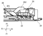
- a central member 26 is provided below the axial flow fan 30 and above the blow-out panel 20 (in the illustrated example, a protrusion toward the axial flow fan 30)
- the shape is not limited thereto, and the shape may be changed as appropriate).
- the central member 26 is provided with a wind guide piece 261.
- the end point of the suction end of the air guide piece 261 is located at the extension of the link body of the link 24.
- the air guide pieces 261 when viewed along the Z direction, are arc-shaped.
- the air guide piece 261 includes a first air guide piece 261A and a second air guide piece 261B.
- the first wind guide piece 261A is a portion of the second wind guide piece 261B around the center of the blowout panel. It is located on the upstream side in the clockwise direction.
- one first link 24A and one second link 24B are provided on one side of the outlet CF. And, one first air guide piece 261A and one second air guide piece 261B are provided.
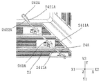
- the first link 24A includes a link main body 241A in which the guide vanes 23 are rotatably provided, and a connection portion 242A.
- the connection portion 242A is located in the center direction of the blowout panel 20 relative to the link main body 241A, and connects the link main body 241A and the inner frame 22. Further, when viewed along the Z direction, the second surface 2421A of the connection portion 242A forms a concave shape inward together with the second surface 2411A of the link main body 241A.
- connection portion 242A connects the first portion 2423A substantially extending along the extension direction of the link main body 241A and the first portion 2423A to the inner frame 22.
- the second portion 2424A both have a guide surface that exerts a guiding action.
- the end faces of the first portion 2423A and the second portion 2424A approaching in the center direction of the blowout panel are both arc-shaped guide surfaces.
- the end face of the second portion 2424A remote from the center direction of the outlet panel is a chamfered surface extending toward the corner of the outlet CF (that is, the closer the corner of the outlet CF is, The upwind face and the downwind face are closer).
- the chamfered surface guides the air flow generated by the axial flow fan or the like to the corner of the outlet CF.
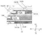
- the second link 24B includes a link main body 241B in which the guide vanes 23 are rotatably provided, and a connection portion 242B.
- the connection portion 242B is located closer to the center of the blowout panel 20 than the link main body 241B, and connects the link main body 241B and the inner frame 22.
- the second surface 2421B of the connection portion 242B forms a concave shape inward together with the second surface 2411B of the link main body 241B.
- the connecting portion 242 B connects the first portion 2423 B substantially extending along the extending direction of the link main body 241 B, and the first portion 2423 B to the inner frame 22.
- the first part and the second part both have a guide surface that exerts a guiding action.
- the end faces of the first portion 2423B and the second portion 2424B approaching in the center direction of the blowout panel are both arc-shaped guide surfaces.
- the end face of the second portion 2424B remote from the center direction of the outlet panel is a chamfered surface extending toward the corner of the outlet CF. The chamfered surface guides the air flow generated by the axial flow fan or the like to the corner of the outlet CF.
- the wind surface which is the second surface 2411A of the link main body 241A
- the wind surface which is the first surface 2412A
- the second surface 2421A of the connection portion 242A and the first surface 2422A are substantially flat.
- the second surface 2411A of the link main body 241A intersects with the second surface 2421A of the connection portion 242A.
- the first surface 2412A of the link main body 241A is substantially flush with the first surface 2422A of the connection portion 242A, or forms an obtuse angle larger than the second surface.
- the air flow guided from the air guide piece can be guided to the link main body 2412A along the first surface 2422A of the connection portion 242A, and can be further guided to the corner of the outlet CF.
- the wind surface that is the second surface 2411B of the link main body 241B and the wind surface that is the first surface 2412B are substantially flat.
- the second surface 2421B of the connection portion 242B and the first surface 2422B are substantially flat.
- the second surface 2411B of the link main body 241B intersects with the second surface 2421B of the connection portion 242B.
- the first surface 2412B of the link main body 241B forms an obtuse angle that is substantially flush with the first surface 2422B of the connection portion 242B or larger than the wind surface. For this reason, the air flow guided from the air guide piece can be guided to the link main body 2412B along the first surface 2422B of the connection portion 242B, and can be further guided to the corner of the outlet CF.
- the second surface 2421A of the connection portion 242A makes an obtuse angle with the second surface 2411A of the link main body 241A.
- the second surface 2421B of the connection portion 242B makes an obtuse angle with the second surface 2411B of the link main body 241B. Therefore, when the air flow generated by the axial flow fan or the like flows to the link main bodies 241A and 241B along the connection portions 242A and 242B, the direction of the air flow gradually changes. As a result, turbulent flow is less likely to be formed at the connection portions between the second surfaces 2421A and 2421B of the connection portions 242A and 242B and the second surfaces 2411A and 2411B of the link main bodies 241A and 241B.
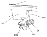
- the pivot shaft 29 of the guide vanes 23 is pivotally connected to the link main body 241A in a substantially horizontal state.
- the guide vanes 23 include an elongated vane main body 231 and a fixing piece 232.
- the fixed piece 232 is perpendicular to the blade main body 231, and one end of the rotating shaft 29 is connected.
- the first link 24A has a projecting piece 243 that protrudes in a direction intersecting the longitudinal direction of the first link 24A.
- the projecting piece 243 constitutes a support portion for supporting the pivot shaft 29.
- the other end of the pivot shaft 29 is pivotally connected to the projecting piece 243.
- the protruding piece 243 is provided on the link main body 241A, and is closer to the corner of the outlet CF than the fixed piece 232. Since the boundary between the connection portion 242A and the link main body 241A is located between the inner frame 22 and the pivot shaft 29, the guide vanes 23 are stably pivoted.
- the projecting piece 243 includes a first portion 2431 and a second portion 2432 extending from the link main body 241A along the thickness direction of the blowout panel 20.
- the second portion 2432 extends at an angle to the first portion 2431 and is parallel to the fixing piece 232.
- the other end of the pivot shaft 29 is pivotally connected to the second portion 2432.
- the pivot shaft of the guide vanes 23 is pivotally connected to the link main body 241B in a substantially horizontal state.
- the guide vanes 23 include a vane main body 231 having a long shape and a fixing piece 232.
- the fixed piece 232 is perpendicular to the blade main body 231, and one end of the pivot shaft 29 is connected.
- the second link 24B has a projecting piece 243 which protrudes in a direction intersecting with the longitudinal direction of the second link 24B.
- the projecting piece 243 constitutes a support portion for supporting the pivot shaft 29.
- the other end of the pivot shaft 29 is pivotally connected to the projecting piece 243.
- the protruding piece 243 is provided on the link main body 241B, and is closer to the corner of the outlet CF than the fixed piece 232. Since the boundary between the connection portion 242B and the link main body 241B is located between the inner frame 22 and the pivot shaft 29, the guide vanes 23 rotate stably.
- the projecting piece 243 includes a first portion 2431 and a second portion 2432 extending from the link main body 241B along the thickness direction of the blowout panel 20.
- the second portion 2432 extends at an angle to the first portion 2431 and is parallel to the fixing piece 232.
- the other end of the pivot shaft 29 is pivotally connected to the second portion 2432.
- a buffer ring 291 is integrally formed on the rotating shaft 29.
- the buffer ring 291 is located between the fixed piece 232 and the projecting piece 243 when the guide vanes 23 are attached.
- the buffer ring 291 prevents clogging of the pivoting rotation of the guide vanes or acceleration of wear of the fixed piece or the like due to the friction between the fixed piece 232 and the protruding piece 243.
- the other end of the pivot shaft 29 is hollow and divided into four pieces, it is possible to form a space of elastic deformation, which is convenient for attaching and detaching the guide vanes 23.
- One end of the pivot shaft 29 may be integrally formed with the fixed piece 232 or may be fixedly adhered to the fixed piece 232.
- the first link 24A and the second link 24B are provided at both ends in the longitudinal direction of the same guide vane 23 via the pivot shaft 29, respectively.
- the provided projecting piece 243 is pivotally connected.
- the protruding pieces 243 provided on the first link 24A and the second link 24B are provided closer to the corner of the outlet CF than the fixing pieces 232 provided on both ends of the guide vanes. ing. That is, the fixing pieces 232 at both ends of the guide vanes 23 are respectively provided on different sides of the first link 24A and the second link 24B. For this reason, compared with the case where the fixed piece 232 is provided on the same side of the first link 24A and the second link 24B, the pivot shaft 29 is prevented from dropping off the projecting piece 243.
- the first link 24A and the second link 24B on both sides of the same corner of the outlet CF are the links of the first link 24A whose link main body is the second link 24B. It is formed to be parallel to the body.
- the suction end of the air guide piece 261 is located at the extension of the first surface of the link body of the link 24, and the blow end of the air guide piece 261 is the link Closer to the vertical line CX than 24.
- the suction end 261AA of the first air guiding piece 261A is located at the extension line YC1 of the first surface 2412A of the link main body 241A of the first link 24A.
- the suction end 261AB of the second wind guide piece 261B is located at the extension line YC2 of the first surface 2412B of the link main body 241B of the second link 24B.
- the outlet end 261BA of the first air guiding piece 261A is closer to the vertical line CX than the first link 24A.
- the blowout end 261BB of the second air guiding piece 261B is closer to the vertical line CX than the second link 24B.
- the point X farthest from the vertical line CX in the leeward surface of the second air guide piece 261B is located at the extension line YC3 of the second surface 2421B of the connection portion 242B of the second link 24B. Therefore, the air flow guided from the leeward surface of the suction end of the second air guide piece 261B flows along the first surface of the second link 241B to the corner of the blowout panel CF.
- the air flow guided from the leeward surface of the outlet end of the second air guide piece 261B flows to the second surface 2421B of the connection portion 242B of the second link 241B.
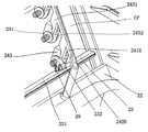
- the blowout panel 20 is further provided with an intermediate link 25.
- the intermediate link 25 connects the outer frame 21 and the inner frame 22.
- the intermediate link 25 is located in the middle of the outlet CF and perpendicular to the guide vanes 23.
- a stepping motor (not shown) for driving the pivoting of the guide vanes 23 is attached to the intermediate link 25.
- the first link 24A and the second link 24B are provided substantially symmetrically with respect to the intermediate link 25.
- the guide vanes 23 are inverted to a predetermined angle with respect to the outer surface of the blowout panel 20, and in the thickness direction of the blowout panel There is a gap between the top edge of the and the link 24 (the link body) for the air flow generated by the axial fan and the like to flow.
- the guide vanes 23 are inverted to a maximum angle (for example, 75 °, 90 °, etc.) with respect to the outer surface of the blowout panel 20, the guide vanes 23 (the uppermost edge thereof) and the link 24 A gap of about 5 mm is secured between (the link body).
- this gap may be longer than 5 mm on the premise that the size reduction of the blowout panel is not affected in order to expand the flow path of the air flow. And this gap may be shorter than 5 mm in order to ensure that even if the guide vanes 23 are reversed, they do not interfere with the link.
- the wind guide piece 261 at least partially overlaps the link 24 when viewed in the horizontal direction.
- the link 24 is located in the middle of the air guide piece 261.
- the air flow generated by the axial flow fan or the like flows to the connecting portion of the link 24 through the windward surface of the air guiding piece 261 and is guided to the corner of the outlet CF along the link main body.
- the air guide piece 261 can be easily provided on the central member 26.
- the central member 26 has an arc-shaped air guide surface, the air flow generated by the axial fan and the like can be guided to the air outlet CF.
- the air conditioning indoor unit 1 further includes an edge frame member 28 provided so as to surround the axial flow fan 30.
- the central member 26 has a support rod 262 and is connected to the side frame member 28 via the support rod 262.
- the support rod 262 is located between the air guide piece 261 and the link 24 when viewed along the Z direction.
- at least a part of the air guide piece 261 is provided offset from the support rod 262 when viewed along the horizontal direction (in the illustrated example, the support rod 262 It extends upward radially outward from the side where the piece 261 is located).
- the one side which faces the axial flow fan 30 of the support rod 262 is an arc shaped surface, an airflow can be guided, reducing obstruction to the air flow which the axial flow fan etc. generated.
- the blowout panel 20 is further provided with a weather strip 27.
- the weather strip 27 is provided at each corner of the outlet CF, and connects the outer frame 21 and the inner frame 22.
- the air flow is sucked into the indoor unit main body 10 from the suction port JP by the action of the axial flow fan 30, and the filter component 40 and the heat exchanger
- the air flows sequentially to the center of the air conditioning indoor unit 1.
- the air flow then flows through the axial fan 30 to form a spiral air flow and flows to the lower central member 26.
- the air flow is guided by the arc-shaped air guide surface of the central member 26 and diffuses from the center of the blowout panel 20 to the four circumferences to the blowout port CF, of which a part of the air flow is provided to the central member 26
- the air guide piece 261 guides the air to the corner of the air outlet CF.
- the air flow flows from below the support rod 262 and is guided to the corner of the outlet CF via the link 24. Finally, an air stream flows through the outlet CF.
- the guide vanes 23 provided at the outlet CF are driven by a motor and inverted to a predetermined angle to guide the air flow to the outside of the air conditioning indoor unit 1.
- the polygonal blowout port CF is surrounded by the outer frame 21 and the inner frame 22. For this reason, it is possible to realize blowing all around the 360 °. Since the link 24 to which the guide vanes 23 are attached extends from the center direction of the outlet panel 20 to the corner of the outlet CF, the air flow blown out from the axial fan 30 blows along the link 24. It becomes easy to flow to the corner of outlet CF, and blows out by outlet CF close uniformly.
- the link 24 since the link 24 connects the outer frame 21 and the inner frame 22, the strength of the entire blowout panel 20 is enhanced.
- the link 24 is provided in the vicinity of the corner bisector of the corner of the outlet CF. Specifically, the link 24 is provided so as to be parallel to the corner bisector of the corner of the outlet CF. Therefore, the air flow blown out from the axial flow fan 30 is more likely to flow along the link 24 to the corner of the blowout port CF, and the blowout by the blowout port CF is made to approach uniformly.
- one end of the connection portion of the link 24 remote from the link main body is arc-shaped. For this reason, it is possible to reduce the obstruction to the air flow generated by the axial flow fan 30 from the end on one side of the connection portion of the link 24 away from the link main body. Since the end portion is arc-shaped, the air flow generated by the axial flow fan and the like can be guided to the corner of the outlet CF, and the outlet CF can uniformly blow out.
- the width of the connection portion of the link 24 is gradually narrowed toward one side of the link main body. Not only the overall strength is secured, but also the volume of the link 24 can be reduced, which helps to reduce the obstruction to the air flow generated by the axial flow fan 24 from the connection of the link 24, outlet CF Make the blowout by the uniform.
- the second surface of the connection portion of the link 24 when viewed along the Z direction, is combined with the second surface of the link main body, and is directed inward. Form a concave shape. Therefore, it is easy to guide the air flow generated by the axial fan 30 to the corner of the outlet CF via the second surface of the link body using the second surface of the connection portion of the link 24. Become. As a result, the air flow comes to be blown out also from the corner of the blowout port, and furthermore, the blowout over 360 ° by the blowout panel approaches realization.
- the second surface of the connection portion of the link 24 forms an obtuse angle with the second surface of the link main body. Therefore, the guiding effect on the air flow generated by the axial fan 30 by the second surface of the connection portion of the link 24 can be secured. Moreover, the obstruction to the airflow which the axial flow fan 30 generate
- the first link 24A and the second link 24B on both sides of the same corner of the outlet CF are the link main bodies 241A of the first link 24A.
- the second link 24B is formed to be parallel to the link body 241B.
- the intermediate link 25 is attached with a stepping motor for driving the pivoting of the guide vanes 23. Therefore, the force received by the guide vanes 23 approaches uniformly, and the drive structure can be simplified.
- the provision of the stepping motor in the outer frame of the blowout port is also advantageous for downsizing of the blowout panel.
- the central member 26 is provided at the center of the inner frame 22.
- the air guide piece 261 is provided on the central member 26. For this reason, by guiding the air flow generated by the axial fan 30 using the air guide pieces 261, the air flow is prevented from being directly blown downward, and the blowout by the blowout port CF approaches uniform.
- the suction end of the air guide piece 261 is located at the extension of the first surface of the link main body of the link 24. Therefore, it is possible to further secure the air flow flowing to the corner portion of the outlet CF, and the outlet by the outlet CF approaches uniformly, and the outlet of the outlet panel over 360 ° is realized.
- the link 24 is located in the middle of the air guide piece 261 in the Z direction. For this reason, the interaction between the air guide piece 261 and the link 24 is reinforced, the air flow flowing to the corner of the outlet CF is secured, and the outlet by the outlet CF approaches uniform.
- blowing panel and the air conditioning indoor unit were described as an example, linking each drawing, the concrete realization of the blowing panel and the air conditioning indoor unit is not restricted by the above-mentioned embodiment.
- the air-conditioning indoor unit including the indoor unit body and the blowout panel provided below the indoor unit body
- the blowout panel is connected to the air processing device via a duct, and the spiral air flow discharged from the blowing component in the air treatment device is blown to the blowout panel via the duct and is further discharged from the blowout panel.
- the blowing panel and an air-conditioning indoor unit may be sufficient.
- the indoor unit main body 10 is a shape of a substantially rectangular parallelepiped from the whole
- the shape of the indoor unit main body may be suitably changed according to a condition.
- it may be formed in a substantially cylindrical shape, or may be formed in a prismatic shape other than a quadrangular prism.
- the blowout panel 20 is substantially rectangular when viewed from the Z direction, but the shape of the blowout panel may be appropriately changed according to the situation.
- it when viewed from the Z direction, it may have a substantially circular shape, or when viewed from the Z direction, it may be formed in a shape such as a polygon other than a quadrangle.
- blower outlet CF is a square, it is not restricted to it, What is necessary is just to form a blower outlet into a polygon.
- suction port JF is provided in each side of the indoor unit main body 10 and the filter component 40 is provided in each suction port JF, the suction port and the filter component The number of may be adjusted as needed.
- one first link 24A and one second link 24B are provided on one side of the outlet CF, and one first air guide piece 261A, One second air guide piece 261B is provided.
- the number of the first link 24A, the second link 24B, the first air guiding piece 261A, and the second air guiding piece 261B provided on one side of the outlet CF may be as necessary. May be changed.
- the link 24 connects the outer frame 21 and the inner frame 22.
- the link 24 may be connected to only one of the outer frame 21 and the inner frame 22.
- the link 24 includes the first link 24A and the second link 24B.
- the link 24 may include only one of the first link 24A and the second link 24B.
- the air guide piece 261 includes the first air guide piece 261A and the second air guide piece 261B.
- the air guide piece 261 may be the first air guide piece 261A. And only one of the second air guiding pieces 261B.
- the second surface 2411A of the link main body 241A and the first surface 2412A are substantially flat, and the second surface 2421A of the connection portion 242A and the first surface
- the surface 2422A of 1 is substantially planar.
- the second link 24B the second surface 2411B and the first surface 2412B of the link main body 241B are substantially flat, and the second surface 2421B and the first surface 2422B of the connecting portion 242B. , Is substantially flat.
- the present invention is not limited thereto, and the second surface 2411A, the first surface 2412A, and the second surface 2421A, the first surface 2422A of the connecting portion 242A of the link main body 241A may be formed in other shapes.
- connection portion 242B when viewed from the Z direction, it may be formed in an arc shape, a broken line shape, or the like).
- the second surface 2411B and the first surface 2412B of the link main body 241B, and the second surface 2421B and the first surface 2422B of the connection portion 242B may be formed in another shape (for example, from the Z direction) When viewed, it may be formed into an arc, a broken line, etc.
- first link 24A and the second link 24B on both sides of the same corner of the outlet CF are the link main body of the first link 24A and the link main body of the second link 24B.
- the present invention is not limited thereto, and the link body of the first link 24A and the link body of the second link 24B may be formed so as not to be parallel.
- the wind guide piece 261 is arc-shaped when viewed from the Z direction.
- the shape is not limited thereto, and the shape of the air guide piece may be appropriately changed as needed.
- the suction end of the air guide piece 261 is located at an extension of the first surface of the link body of the link 24.
- the invention is not limited thereto, and the suction end of the air guide piece may be positioned substantially in the extending direction of the link body of the link.
- the specific form of the rotational axis 29 may be suitably changed as needed.
- the pivot shaft 29 may be a simple rod-like or tubular member or a joint.
Abstract
A blow-out panel (20), and an air conditioning indoor unit (1) that includes the blow-out panel (20), approach the realization of blow-out across the entire circumference of 360° using a simple structure and also approach uniformity in the blow-out by a blow-out port. This blow-out panel (20) has an outer frame (21) and an inner frame (22). A polygonal blow-out port (CF) is surrounded by the outer frame (21) and the inner frame (22). Guide blades (23) are provided in the blow-out port (CF). Links (24) are provided to the blow-out panel (20). The links (24) are offset from corner parts of the blow-out port (CF) and extend from the central direction of the blow-out panel (20) to the corner parts of the blow-out port (CF). The guide blades (23) are pivotally connected to the links (24) in a state of being parallel to the longitudinal direction of the guide blades (23).
Description
吹出パネル、および、その吹出パネルを含む空調室内機に関する。
The present invention relates to a blowout panel and an air conditioning indoor unit including the blowout panel.
従来、回転軸線が上下方向に沿って延伸している軸流ファンが内部に設けられた室内機本体と、その室内機本体の下方に設けられており、案内羽根が内部に設けられた吹出口を有する吹出パネルと、を備えた空調室内機が存在している。
Conventionally, an indoor unit body internally provided with an axial flow fan whose rotation axis extends along the vertical direction, and a blowout port provided below the indoor unit body and provided with a guide blade inside And a blowout panel having the
上記の空調室内機において、吹出口による吹出し面積を増大させるために、配置の利便性を考慮して、方形の外枠と方形の内枠とを有し、かつ、外枠と内枠で囲まれた多角形の吹出口を有する吹出パネルを採用することが考えられる。
In the above-mentioned air conditioning indoor unit, in order to increase the blowing area by the air outlet, in consideration of the convenience of arrangement, it has a rectangular outer frame and a rectangular inner frame, and is surrounded by the outer frame and the inner frame. It is conceivable to adopt a blowout panel having a tapered polygonal blowout.
しかし、この場合には、軸流ファンから発生した気流が吹出口の角部に吹き出されにくくなり、吹出口による吹出しが不均一となりやすい。
However, in this case, the air flow generated from the axial flow fan is less likely to be blown out to the corner of the blowout port, and the blowout by the blowout port tends to be uneven.
また、上記の場合には、案内羽根を、どのように、簡単な構成で、吹出パネルに取り付けるかについて、考慮する必要もある。
In the above case, it is also necessary to consider how the guide vanes are attached to the blowout panel with a simple configuration.
また、従来、ダクトによって、多角形の吹出パネルに接続されている空気処理機器が存在している。空気処理機器における送風部品から排出された螺旋気流は、ダクトを介して吹出パネルに送風される。その場合には、螺旋気流が吹出口の角部に吹き出されにくくなり、吹出口による吹出しが不均一となりやすい。
Also, conventionally, there are air treatment devices connected by a duct to a polygonal outlet panel. The spiral air flow discharged from the air blowing component in the air processing apparatus is blown to the blowout panel through the duct. In that case, it becomes difficult for the spiral air flow to be blown out to the corner of the blowout port, and the blowout by the blowout port tends to be uneven.
上記の技術的課題を解決するため、吹出パネルは、外枠と内枠を有している。外枠と内枠により、多角形の吹出口が囲まれている。吹出口の内には、案内羽根が設けられている。吹出パネルには、リンクが設けられている。リンクは、吹出口の角部からずれて、吹出パネルの中心方向から吹出口の角部へ延伸している。案内羽根の回動軸は、案内羽根の長手方向と平行な状態で、リンクに枢動接続されている。
In order to solve said technical subject, the blowing panel has an outer frame and an inner frame. An outer frame and an inner frame enclose a polygonal outlet. Guide vanes are provided in the blowout port. The blowout panel is provided with a link. The link is offset from the corner of the outlet and extends from the center direction of the outlet panel to the corner of the outlet. The pivot shaft of the guide vane is pivotally connected to the link in parallel with the longitudinal direction of the guide vane.
ここでは、いわゆる「外枠と内枠により、多角形の吹出口が囲まれている」ことは、外枠と内枠の間に、空気を吹出し可能なすべての部分を合わせたほぼ多角形のものを形成したこと、を指す。また、いわゆる「吹出口の角部」とは、外枠と内枠の間に形成された空気を吹出し可能なすべての部分を合わせた多角形の角部、を指す。
Here, the fact that the so-called “outer frame and inner frame enclose a polygonal air outlet” means that the outer frame and the inner frame are substantially polygonal, in which all parts capable of blowing out air are combined. It refers to having formed one. Moreover, the so-called "corner of the outlet" refers to the corner of the polygon which united all the parts which can blow off the air formed between the outer frame and the inner frame.
上記構成の吹出パネルによれば、外枠と内枠で囲まれた多角形の吹出口が用いられたことで、例えば、軸流ファンが設けられた室内機本体を含む空調室内機などを使用する場合に、360°全周に亘る吹出しの実現に近づけることができる。そして、案内羽根が取り付けられたリンクが、吹出パネルの中心方向から吹出口の角部に延伸しているので、例えば、軸流ファンが設けられた室内機本体を含む空調室内機などを使用する場合に、軸流ファンなどから吹出された気流がリンクに沿って吹出口の角部に流れやすくなり、吹出口による吹出しが均一に近づく。
According to the blow-out panel of the above-mentioned configuration, for example, an air-conditioning indoor unit including an indoor unit main body provided with an axial flow fan is used by using a polygonal outlet surrounded by the outer frame and the inner frame. In this case, it is possible to approach the realization of blowing all around 360 °. And since the link to which the guide vanes are attached extends from the center direction of the blowout panel to the corner of the outlet, for example, an air conditioning indoor unit including an indoor unit main body provided with an axial flow fan is used In this case, the air flow blown out from the axial flow fan or the like easily flows along the link to the corner of the blowout port, and the blowout by the blowout port approaches uniform.
また、上記構成の吹出パネルによれば、案内羽根とリンクの接続構造が簡単になるため、回動時における案内羽根のリンクとの干渉を回避することができ、案内羽根をリンクに接続しやすくなる。
Further, according to the blowout panel of the above configuration, the connection structure of the guide vanes and the link is simplified, so that interference with the link of the guide vanes at the time of rotation can be avoided, and the guide vanes can be easily connected to the links. Become.
この吹出パネルでは、好ましくは、リンクは、外枠と内枠とを接続している。
In this blowout panel, preferably, the link connects the outer frame and the inner frame.
上記構成の吹出パネルによれば、吹出パネル全体の強度が強くなり、他の接続部材を増加する必要がない。また、他の接続部材を増加した場合と比べると、他の接続部材による吹出口での気流への阻害を低減し、構造が簡単となるだけではなく、吹出パネルを増大させることも可能になる。
According to the blowing panel of the said structure, the intensity | strength of the whole blowing panel becomes strong, and it is not necessary to increase another connection member. Moreover, compared with the case where other connecting members are increased, the obstruction to the air flow at the outlet by the other connecting members is reduced, and not only the structure becomes simple, but it becomes possible to increase the blowing panel. .
この吹出パネルでは、好ましくは、リンクは、吹出口の角部の角二等分線近傍に設けられている。
In this blowout panel, preferably, the link is provided in the vicinity of the corner bisector of the corner of the outlet.
上記構成の吹出パネルによれば、例えば、軸流ファンが設けられた室内機本体を含む空調室内機などを使用する場合に、軸流ファンなどから吹出された気流がリンクに沿って吹出口の角部に流れやすくなり、吹出口による吹出しが均一に近づく。
According to the blowout panel of the above configuration, for example, when using an air conditioning indoor unit including the indoor unit main body provided with the axial flow fan, the air flow blown out from the axial flow fan or the like is the outlet along the link. It becomes easy to flow to the corner, and the blowout by the blowout approaches uniform.
この吹出パネルでは、好ましくは、案内羽根は、長尺状を呈している羽根本体と、羽根本体と垂直であり回動軸の一端が接続されている固定片と、を備える。リンクは、リンクの長手方向と交差して突出した突片を有し、回動軸の他端が、その突片に枢動接続される。
In this blowout panel, preferably, the guide vane includes an elongated vane body, and a fixing piece perpendicular to the vane body and to which one end of the pivot shaft is connected. The link has a projecting piece protruding in a direction intersecting with the longitudinal direction of the link, and the other end of the pivot shaft is pivotally connected to the projecting piece.
上記構成の吹出パネルによれば、簡単な構造によって、案内羽根とリンクとの枢動接続を実現することができる。
According to the blow-out panel of the above-mentioned configuration, the pivot connection between the guide vanes and the link can be realized by a simple structure.
この吹出パネルでは、リンクは、リンク本体と接続部を備えるものであってもよい。接続部は、リンク本体よりも吹出パネルの中心に位置し、かつ、リンク本体と内枠とを接続している。そして、突片は、リンク本体に設けられている。
In the blowout panel, the link may include the link body and the connection portion. The connection portion is located at the center of the blowout panel rather than the link main body, and connects the link main body and the inner frame. The protrusion is provided on the link body.
上記構成の吹出パネルによれば、吹出パネル全体の強度を強くするができ、他の接続部材を増加する必要がない。また、他の接続部材を増加した場合と比べると、他の接続部材による吹出口での気流への阻害を低減し、構造が簡単となるだけではなく、吹出パネルを増大させることも可能になる。案内羽根とリンクの接続構造が簡単となるため、案内羽根の回動時のリンクとの干渉を回避することができ、案内羽根をリンクに接続しやすくなる。
According to the blowout panel of the above configuration, the strength of the entire blowout panel can be increased, and it is not necessary to increase other connection members. Moreover, compared with the case where other connecting members are increased, the obstruction to the air flow at the outlet by the other connecting members is reduced, and not only the structure becomes simple, but it becomes possible to increase the blowing panel. . Since the connection structure of the guide vanes and the link is simplified, interference with the link when the guide vanes rotate can be avoided, and the guide vanes can be easily connected to the links.
この吹出パネルでは、突片は、リンク本体から吹出パネルの厚さ方向に沿って延伸している第1部分と、その第1部分と角度をなして延伸しており固定片と平行な第2部分とを備えるものであってもよい。回動軸の他端は、第2部分に枢動接続される。
In this blowout panel, the protrusion is a first portion extending along the thickness direction of the blowout panel from the link main body, and a second portion extending at an angle to the first portion and parallel to the fixing piece A part may be provided. The other end of the pivot is pivotally connected to the second part.
上記構成の吹出パネルによれば、突片の第1部分がリンク本体から吹出パネルの厚さ方向に沿って延伸しているので、例えば、軸流ファンが設けられた室内機本体を含む空調室内機などを使用する場合に、突片の第1部分とリンクとが共同で、軸流ファンなどから発生した気流を、吹出パネルの角部に案内することができる。そして、突片の第2部分が固定片とは平行であるため、回動軸の構造が簡単となるだけではなく、組み立てを行いやすくなり、組み立てられた構造がコンパクトであり、回動中における回動軸の摩損を低減することもできる。
According to the blowout panel of the above configuration, the first portion of the projection extends from the link body along the thickness direction of the blowout panel, so, for example, an air conditioning chamber including the indoor unit main body provided with the axial flow fan When using a machine or the like, the first portion of the projecting piece and the link can jointly guide the air flow generated from the axial flow fan or the like to the corner of the blowout panel. And since the 2nd part of a projection piece is parallel to a fixed piece, not only structure of a rotation axis becomes simple, but it becomes easy to assemble and an assembled structure is compact, and during rotation It is also possible to reduce the wear and tear of the pivot shaft.
この吹出パネルでは、突片は、固定片よりも吹出口の角部に接近する、という構成であってもよい。
In the blowout panel, the projection may be closer to the corner of the outlet than the fixing piece.
上記構成の吹出パネルによれば、固定片及び回動軸の一端からの吹出口の角部での気流への阻害を低減することができる。
According to the blowing panel of the said structure, obstruction to the air flow in the corner | angular part of the blower outlet from the fixing piece and the end of a rotational axis can be reduced.
この吹出パネルでは、好ましくは、リンクは、吹出口の一辺に設けられた第1のリンク及び第2のリンクを備える。吹出パネルの内面側から外面側へ見たときに、第2のリンクは、第1のリンクの、吹出パネルの中心回りの時計回り方向の下流側に位置している。そして、案内羽根に、第1のリンク及び第2のリンクのそれぞれに枢動接続されている第1の回動軸と第2の回動軸、が設けられている。
In the blowout panel, preferably, the link includes a first link and a second link provided on one side of the outlet. When viewed from the inner surface side to the outer surface side of the blowout panel, the second link is located downstream of the first link in the clockwise direction about the center of the blowout panel. The guide vane is provided with a first pivot and a second pivot pivotally connected to each of the first link and the second link.
ここでは、いわゆる「吹出パネルの外面」とは、吹出パネルが部屋などに取り付けられた場合の使用者に向かう面を指し、「吹出パネルの内面」とは、「吹出パネルの外面」との反対側の面を指す。
Here, the so-called "outer surface of the blowout panel" refers to the surface facing the user when the blowout panel is attached to a room or the like, and the "inner surface of the blowout panel" is the opposite of "the outer surface of the blowout panel". Point to the side surface.
上記構成の吹出パネルによれば、吹出パネル全体の強度を強くすることができ、案内羽根の組立ての頑丈さを向上させ、案内羽根の反転中にさらに安定化される。
According to the blowout panel of the above configuration, the strength of the entire blowout panel can be increased, the assembly strength of the guide vanes can be improved, and the stability can be further stabilized during the inversion of the guide vanes.
この吹出パネルでは、中間リンクがさらに設けられ、案内羽根に、当該中間リンクに枢動接続されている中間回動軸が設けられた構成を採ってもよい。吹出パネルの厚さ方向から見たときに、中間リンクは、吹出口の中間に位置し、かつ、案内羽根と垂直である。中間リンクには、案内羽根の回動を駆動するステッピングモータが取り付けられている。
In the blowout panel, an intermediate link may be further provided, and the guide vane may be provided with an intermediate pivot shaft pivotally connected to the intermediate link. When viewed from the thickness direction of the blowout panel, the intermediate link is located at the middle of the blowout port and perpendicular to the guide vanes. The intermediate link is attached with a stepping motor that drives the rotation of the guide vanes.
上記構成の吹出パネルによれば、案内羽根が受ける力を均一に近づけることができる。これにより、安定性が良く、駆動構造も簡単となる。また、吹出口の外枠の位置にステッピングモータを設けることにより、吹出パネルの小型化にも有利である。
According to the blowing panel of the said structure, the force which a guide blade receives can be closely approached uniformly. This improves the stability and simplifies the drive structure. Further, by providing the stepping motor at the position of the outer frame of the blowout port, it is also advantageous to miniaturize the blowout panel.
この吹出パネルでは、好ましくは、リンクは、リンク本体と接続部を備える。接続部は、リンク本体よりも吹出パネルの中心に位置し、かつ、リンク本体と内枠とを接続している。接続部とリンク本体は、それぞれ、第1の面と第2の面を有する。吹出パネルの内面側から外面側へ見たときに、第1の面は、第2の面の、吹出パネルの中心回りの時計回り方向の下流側に位置している。接続部の第2の面は、リンク本体の第2の面と合わせて、内への凹形状を形成する。
In the blowout panel, preferably, the link comprises a link body and a connection. The connection portion is located at the center of the blowout panel rather than the link main body, and connects the link main body and the inner frame. The connection portion and the link body each have a first surface and a second surface. When viewed from the inner surface side to the outer surface side of the blowout panel, the first surface is located on the downstream side of the second surface in the clockwise direction about the center of the blowout panel. The second surface of the connection together with the second surface of the link body forms an inward concave shape.
上記構成の吹出パネルによれば、リンク全体の強度を確保することができるだけではなく、リンクの体積を減少することもできる。例えば、軸流ファンが設けられた室内機本体を含む空調室内機などを使用する場合に、リンクの接続部からの軸流ファンなどが発生した気流への阻害を低減することができ、吹出口による吹出しが均一に近づく。そして、リンクの接続部の第2の面を用いて、軸流ファンなどが発生した気流を、リンク本体の第2の面を介して、吹出口の角部へ案内することが容易となり、吹出口の角部からも、気流が吹出されるようになり、さらに、吹出パネルによる360°に亘る吹出しを実現させる。
According to the blowout panel of the above configuration, not only can the strength of the entire link can be ensured, but also the volume of the link can be reduced. For example, in the case of using an air conditioning indoor unit including an indoor unit main body provided with an axial fan, the obstruction to the air flow generated from the axial fan or the like from the connection of the link can be reduced. The blowout due to becomes close to uniform. Then, using the second surface of the link connection portion, it becomes easy to guide the air flow generated by the axial fan and the like to the corner of the outlet through the second surface of the link main body. Also from the corner of the outlet, the air flow comes to be blown out, and furthermore, the blowout panel achieves 360 ° blowing.
この吹出パネルでは、好ましくは、リンクは、吹出口の一辺に設けられた第1のリンク及び第2のリンクを備える。吹出パネルの内面側から外面側へ見たときに、第2のリンクは、第1のリンクの、吹出パネルの中心回りの時計回り方向の下流側に位置している。吹出口の同一の角部の両側における第1のリンクと第2のリンクは、第1のリンクのリンク本体が第2のリンクの前記リンク本体と平行であるように形成されている。
In the blowout panel, preferably, the link includes a first link and a second link provided on one side of the outlet. When viewed from the inner surface side to the outer surface side of the blowout panel, the second link is located downstream of the first link in the clockwise direction about the center of the blowout panel. The first link and the second link on both sides of the same corner of the outlet are formed such that the link body of the first link is parallel to the link body of the second link.
上記構成の吹出パネルによれば、吹出パネル全体の構造を簡素化することができ、リンクのリンク本体からの吹出口の角部での気流への阻害を低減することができ、吹出口による吹出しが均一に近づく。
According to the blowout panel of the above configuration, the entire structure of the blowout panel can be simplified, and obstruction to the air flow at the corner of the blowout from the link main body of the link can be reduced. Approaches uniform.
この吹出パネルでは、好ましくは、内枠の中央には、導風片が設けられた中央部材が設置される。
In the blowout panel, preferably, a central member provided with a wind guide piece is installed at the center of the inner frame.
上記構成の吹出パネルによれば、例えば、軸流ファンが設けられた室内機本体を含む空調室内機などを使用する場合に、導風片を用いて軸流ファンなどが発生した気流を案内することにより、気流が下向きに直接吹出されることを防止し、かつ、導風片により案内された気流がリンクに沿って吹出口の角部に流れるようになり、吹出口による吹出しが均一に近づく。
According to the blow-out panel of the above configuration, for example, when using an air-conditioning indoor unit including an indoor unit main body provided with an axial flow fan, the air guide piece is used to guide the air flow generated by the axial flow fan or the like. Thereby, the air flow is prevented from being directly blown downward, and the air flow guided by the air guide piece flows along the link to the corner of the blowout port, and the blowout by the blowout port approaches uniform. .
この吹出パネルでは、リンクは、リンク本体と接続部を備える構成であってもよい。接続部は、リンク本体よりも吹出パネルの中心に位置し、かつ、リンク本体と内枠とを接続している。リンク本体は、第1の面と第2の面を有する。吹出パネルの内面側から外面側へ見たときに、第1の面は、第2の面の、吹出パネルの中心回りの時計回り方向の下流側に位置している。導風片の吸込み端は、リンク本体の第1の面の延長線に位置している。
In the blowout panel, the link may be configured to include the link body and the connection portion. The connection portion is located at the center of the blowout panel rather than the link main body, and connects the link main body and the inner frame. The link body has a first side and a second side. When viewed from the inner surface side to the outer surface side of the blowout panel, the first surface is located on the downstream side of the second surface in the clockwise direction about the center of the blowout panel. The suction end of the wind guide piece is located at an extension of the first surface of the link body.
上記構成の吹出パネルによれば、吹出口の角部へ流れる気流をさらに確保することができ、吹出口による吹出しが均一に近づき、吹出パネルによる360°に亘る吹出しを実現することができる。
According to the blowout panel of the above configuration, it is possible to further secure the air flow flowing to the corner of the blowout port, the blowout by the blowout port approaches uniformly, and the blowout panel can realize blowout over 360 °.
また、上記の技術的課題を解決するために、空調室内機は、室内機本体と、上記の吹出パネルと、を備える。吹出パネルは、室内機本体と直接に接続されている、又は、ダクトを介して室内機本体に接続されている。
Moreover, in order to solve said technical subject, an air conditioning indoor unit is provided with the indoor unit main body and said blowing panel. The blowout panel is directly connected to the indoor unit body, or connected to the indoor unit body via a duct.
以下、図1~10を参照しながら、室内機本体と吹出パネルを備えた空調室内機を例にして、実際の装着状態に応じて、実施の形態を説明する。
The embodiment will be described below with reference to FIGS. 1 to 10, taking an air conditioning indoor unit provided with an indoor unit main body and a blowout panel as an example, according to an actual mounting state.
ここでは、説明の便宜上、互いに直交する3つの方向を、X方向、Y方向、Z方向に設定し、そのうち、X方向とY方向は、空調室内機の実際の装着状態での水平面内の方向に対応し、Z方向は、空調室内機の実際の装着状態での上下方向に対応する。Y1方向側、Y2方向側、X1方向側、X2方向側、Z1方向側、および、Z2方向側は、それぞれ、空調室内機の実際の装着状態での前側、後側、左側、右側、下側、および、上側に対応する。
Here, for convenience of explanation, three directions orthogonal to one another are set as the X direction, the Y direction, and the Z direction, and among them, the X direction and the Y direction are the directions in the horizontal plane in the actual mounting state of the air conditioning indoor unit , And the Z direction corresponds to the vertical direction in the actual mounting state of the air conditioning indoor unit. The Y1 direction side, the Y2 direction side, the X1 direction side, the X2 direction side, the Z1 direction side, and the Z2 direction side are the front side, the rear side, the left side, the right side, and the lower side in the actual mounting state of the air conditioning indoor unit, respectively. And correspond to the upper side.
図1に示すように、空調室内機1は、軸流ファン30が内部に設けられた室内機本体10と、室内機本体10に接続されている吹出パネル20とを備える(図示の例では、吹出パネル20は室内機本体10の下方に設けられている)。
As shown in FIG. 1, the air conditioning indoor unit 1 includes an indoor unit main body 10 in which an axial fan 30 is provided, and a blowout panel 20 connected to the indoor unit main body 10 (in the illustrated example, The blowout panel 20 is provided below the indoor unit body 10).
ここでは、室内機本体10は、全体からすると、略直方体の形状を呈しており、上面、底面及び4つの側面を有する。各側面には、吸気口JFが設けられており、各吸気口JPにて、フィルタ部品40が設けられている。図1に示すように、室内機本体10の内部には、熱交換器50がさらに設けられている。熱交換器50は、吸気口JFの内側に設けられて、フィルタ部品40によって囲まれている。また、熱交換器50の内側には、軸流ファン30が設けられている。軸流ファン30は、回転軸線が吹出パネル20の中心軸線L(すなわち、吹出パネル20の中心を通って吹出パネル20の厚さ方向に沿って延伸している軸線)と重なるように設けられている。
Here, the indoor unit body 10 has a substantially rectangular parallelepiped shape overall, and has an upper surface, a bottom surface, and four side surfaces. An intake port JF is provided on each side surface, and a filter component 40 is provided at each intake port JP. As shown in FIG. 1, a heat exchanger 50 is further provided inside the indoor unit body 10. The heat exchanger 50 is provided inside the inlet JF and surrounded by the filter component 40. In addition, an axial flow fan 30 is provided inside the heat exchanger 50. The axial fan 30 is provided so that the rotation axis overlaps the central axis L of the blowout panel 20 (that is, an axis extending through the center of the blowout panel 20 along the thickness direction of the blowout panel 20) There is.
また、図1と図2に示すように、吹出パネル20は、外枠21と内枠22を有している。外枠21と内枠22によって、多角形の吹出口CFが囲まれている。吹出口CF内には、案内羽根23が設けられている。吹出パネル20には、リンク24が設けられている。リンク24は、吹出口CFの角部からずれて(すなわち、リンク24が吹出口CFの角部の頂点を通過せずに)、吹出パネル20の中心方向から吹出口CFの角部へ延伸している。リンク24には、案内羽根23が回動可能に取り付けられている。
Further, as shown in FIGS. 1 and 2, the blowout panel 20 has an outer frame 21 and an inner frame 22. A polygonal air outlet CF is surrounded by the outer frame 21 and the inner frame 22. A guide vane 23 is provided in the blowout port CF. The blowout panel 20 is provided with a link 24. The link 24 is offset from the corner of the outlet CF (that is, the link 24 does not pass through the top of the corner of the outlet CF) and extends from the center direction of the outlet panel 20 to the corner of the outlet CF ing. A guide vane 23 is rotatably attached to the link 24.
ここでは、図1と図2に示すように、吹出パネル20の内面側から外面側へ見たときに、具体的には、吹出パネル20の室内機本体10の一方側(Z2方向側)から室内機本体10から離れた一方側(Z1方向側)へ見たときに、リンク24は、第1の面(図2中の時計回り方向の下流側)と第2の面(図2中の時計回り方向の上流側)を有する。軸流ファンなどが発生した気流は、順次、第2の面と第1の面を流れる。すなわち、第2の面は風上面であり、第1の面は風下面である。
Here, as shown in FIG. 1 and FIG. 2, when viewed from the inner surface side to the outer surface side of the blowout panel 20, specifically, from the one side (Z2 direction side) of the indoor unit main body 10 of the blowout panel 20. When viewed from one side (Z1 direction side) away from the indoor unit body 10, the link 24 has a first surface (downstream side in the clockwise direction in FIG. 2) and a second surface (in FIG. 2) (Upstream side in the clockwise direction). The air flow generated by the axial fan and the like sequentially flows through the second surface and the first surface. That is, the second surface is the wind surface, and the first surface is the wind surface.
ここでは、図2に示すように、吹出パネル20は、略方形を呈しており、方形の外枠21と、方形の内枠22とを有している。外枠21と内枠22とによって、方形の吹出口CFが囲まれている。吹出口CFの各辺(各辺によって副吹出口が構成されている)にて、1組の案内羽根23が設けられている。図2と図3に示すように、各組の案内羽根23は、3枚の平行な案内羽根によって組み合わせられている。3枚の平行な案内羽根の長さは、吹出パネル20の内枠22から外枠21への方向に沿って増加していくように設けられている。案内羽根23が回動して吹出口CFを開放させた場合に、案内羽根23の両端での気流は、複数の案内羽根23の端部に沿って下向きに徐々に拡散してしまい、平行に吹出されるものではない。したがって、案内羽根23の両端での、流動速度が相対的に遅い気流は、天井に付着されなくなる。これにより、気流に挟まれた塵埃などの汚染物が天井に付着されてしまうことが、避けられる。そして、全体からすると、大部分の気流は、相変わらず、案内羽根23によって案内されているので、気流が均一に分布している状態を依然として保持することができる。
Here, as shown in FIG. 2, the blowout panel 20 has a substantially rectangular shape, and has a rectangular outer frame 21 and a rectangular inner frame 22. A rectangular air outlet CF is surrounded by the outer frame 21 and the inner frame 22. One set of guide vanes 23 is provided on each side of the blower outlet CF (each side constitutes an auxiliary blower outlet). As shown in FIGS. 2 and 3, each set of guide vanes 23 is combined by three parallel guide vanes. The lengths of the three parallel guide vanes are provided to increase along the direction from the inner frame 22 to the outer frame 21 of the blowout panel 20. When the guide vanes 23 rotate to open the air outlet CF, the air flow at both ends of the guide vanes 23 gradually diffuses downward along the ends of the plurality of guide vanes 23 and is parallel It is not something that is blown out. Therefore, the air flow having a relatively low flow velocity at both ends of the guide vanes 23 is not attached to the ceiling. Thereby, it is avoided that contaminants such as dust caught in the air flow are attached to the ceiling. And as a whole, since most of the air flow is still guided by the guide vanes 23, it is still possible to keep the air flow evenly distributed.
また、図2に示すように、リンク24は、外枠21と内枠22とを接続しており、吹出口CFの角部の角二等分線近傍に設けられている(図示の例では、リンク24は吹出口CFの角部の角二等分線とは平行である)。そして、リンク24は、吹出口の一辺に設けられた第1のリンク24A及び第2のリンク24Bを備えている。Z方向に沿って見たときに(具体的には、図2の視点から見たときに)、吹出口CFの一辺の吹出パネル20の中心を通った垂直線CXは、第1のリンク24Aの、吹出パネルの中心回りの時計回り方向の下流側に位置している。第2のリンク24Bは、垂直線CXの、吹出パネルの中心回りの時計回り方向の下流側に位置している。そのため、第1のリンク24Aと第2のリンク24Bとをそれぞれ用いて、軸流ファンなどが発生した気流を吹出口CFの2つの角部に案内することができ、吹出口CFの2つの角部での気流はともに、均一に分布している状態に近づく。
Further, as shown in FIG. 2, the link 24 connects the outer frame 21 and the inner frame 22 and is provided in the vicinity of a corner bisector of the corner of the outlet CF (in the illustrated example, , Links 24 are parallel to the angular bisector of the corners of the outlet CF). And the link 24 is provided with the 1st link 24A and the 2nd link 24B which were provided in one side of the blower outlet. When viewed along the Z direction (specifically, viewed from the viewpoint of FIG. 2), the vertical line CX passing through the center of the blowout panel 20 on one side of the blowout port CF is the first link 24A. , Located on the downstream side in the clockwise direction around the center of the blowout panel. The second link 24B is located downstream of the vertical line CX in the clockwise direction about the center of the blowout panel. Therefore, the air flow generated by the axial fan and the like can be guided to the two corners of the outlet CF by using the first link 24A and the second link 24B, respectively, and the two corners of the outlet CF Both of the airflows in the section approach a uniformly distributed state.
また、図1~図3に示すように、軸流ファン30の下方であって吹出パネル20の上方に、中央部材26が設けられている(図示の例では、軸流ファン30に向かって突起した形状を呈しているが、それに限られず、その形状は必要に応じて適宜変更されてもよい)。中央部材26には、導風片261が設けられている。導風片261の吸込み端の端点は、リンク24のリンク本体の延長線に位置している。
Further, as shown in FIGS. 1 to 3, a central member 26 is provided below the axial flow fan 30 and above the blow-out panel 20 (in the illustrated example, a protrusion toward the axial flow fan 30) The shape is not limited thereto, and the shape may be changed as appropriate). The central member 26 is provided with a wind guide piece 261. The end point of the suction end of the air guide piece 261 is located at the extension of the link body of the link 24.
また、図2に示すように、Z方向に沿って見たときに、導風片261は、弧状である。導風片261は、第1の導風片261Aと、第2の導風片261Bとを有している。Z方向に沿って見たときに(具体的には、図2の視点から見たときに)、第1の導風片261Aは、第2の導風片261Bの、吹出パネルの中心回りの時計回り方向の上流側に位置している。
Also, as shown in FIG. 2, when viewed along the Z direction, the air guide pieces 261 are arc-shaped. The air guide piece 261 includes a first air guide piece 261A and a second air guide piece 261B. When viewed along the Z direction (specifically, viewed from the viewpoint of FIG. 2), the first wind guide piece 261A is a portion of the second wind guide piece 261B around the center of the blowout panel. It is located on the upstream side in the clockwise direction.
ここでは、図2に示すように、吹出口CFの一辺には、1つの第1のリンク24Aと、1つの第2のリンク24Bと、が設けられている。そして、1つの第1の導風片261Aと、1つの第2の導風片261Bと、が設けられている。
Here, as shown in FIG. 2, one first link 24A and one second link 24B are provided on one side of the outlet CF. And, one first air guide piece 261A and one second air guide piece 261B are provided.
図2と図4に示すように、第1のリンク24Aは、案内羽根23が回動可能に設けられたリンク本体241Aと、接続部242Aと、を備えている。接続部242Aは、リンク本体241Aよりも吹出パネル20の中心方向に位置しており、リンク本体241Aと内枠22とを接続している。また、Z方向に沿って見たときに、接続部242Aの第2の面2421Aは、リンク本体241Aの第2の面2411Aと合わせて、内への凹形状を形成する。ここでは、図6と図8に示すように、接続部242Aは、リンク本体241Aの延伸方向に沿って略延伸している第1部分2423Aと、その第1部分2423Aを内枠22に接続している第2部分2424Aと、を有している。そのうち、第1部分と第2部分は、ともに、案内作用を奏する案内面を有する。具体的には、第1部分2423Aと第2部分2424Aの吹出パネルの中心方向に接近する端面は、ともに、弧状の案内面である。また、第2部分2424Aの吹出パネルの中心方向から離れた端面は、吹出口CFの角部に向かって延伸している面取り面である(すなわち、吹出口CFの角部に近ければ近いほど、風上側の面と風下側の面が近くなる)。この面取り面は、軸流ファンなどが発生した気流を、吹出口CFの角部へ案内する。
As shown in FIGS. 2 and 4, the first link 24A includes a link main body 241A in which the guide vanes 23 are rotatably provided, and a connection portion 242A. The connection portion 242A is located in the center direction of the blowout panel 20 relative to the link main body 241A, and connects the link main body 241A and the inner frame 22. Further, when viewed along the Z direction, the second surface 2421A of the connection portion 242A forms a concave shape inward together with the second surface 2411A of the link main body 241A. Here, as shown in FIG. 6 and FIG. 8, the connection portion 242A connects the first portion 2423A substantially extending along the extension direction of the link main body 241A and the first portion 2423A to the inner frame 22. And the second portion 2424A. Among them, the first part and the second part both have a guide surface that exerts a guiding action. Specifically, the end faces of the first portion 2423A and the second portion 2424A approaching in the center direction of the blowout panel are both arc-shaped guide surfaces. Further, the end face of the second portion 2424A remote from the center direction of the outlet panel is a chamfered surface extending toward the corner of the outlet CF (that is, the closer the corner of the outlet CF is, The upwind face and the downwind face are closer). The chamfered surface guides the air flow generated by the axial flow fan or the like to the corner of the outlet CF.
図2と図5に示すように、第2のリンク24Bは、案内羽根23が回動可能に設けられたリンク本体241Bと、接続部242Bとを備えている。接続部242Bは、リンク本体241Bよりも吹出パネル20の中心方向に位置しており、リンク本体241Bと内枠22とを接続している。また、Z方向に沿って見たときに、接続部242Bの第2の面2421Bは、リンク本体241Bの第2の面2411Bと合わせて、内への凹形状を形成する。同様に、図8に示すように、接続部242Bは、リンク本体241Bの延伸方向に沿って略延伸している第1部分2423Bと、その第1部分2423Bを内枠22に接続している第2部分2424Bと、を有している。そのうち、第1部分と第2部分は、ともに、案内作用を奏する案内面を有する。具体的には、第1部分2423Bと第2部分2424Bの吹出パネルの中心方向に接近する端面は、ともに、弧状の案内面である。第2部分2424Bの吹出パネルの中心方向から離れた端面は、吹出口CFの角部に向かって延伸している面取り面である。この面取り面は、軸流ファンなどが発生した気流を、吹出口CFの角部へ案内する。
As shown in FIGS. 2 and 5, the second link 24B includes a link main body 241B in which the guide vanes 23 are rotatably provided, and a connection portion 242B. The connection portion 242B is located closer to the center of the blowout panel 20 than the link main body 241B, and connects the link main body 241B and the inner frame 22. Further, when viewed along the Z direction, the second surface 2421B of the connection portion 242B forms a concave shape inward together with the second surface 2411B of the link main body 241B. Similarly, as shown in FIG. 8, the connecting portion 242 B connects the first portion 2423 B substantially extending along the extending direction of the link main body 241 B, and the first portion 2423 B to the inner frame 22. And two portions 2424B. Among them, the first part and the second part both have a guide surface that exerts a guiding action. Specifically, the end faces of the first portion 2423B and the second portion 2424B approaching in the center direction of the blowout panel are both arc-shaped guide surfaces. The end face of the second portion 2424B remote from the center direction of the outlet panel is a chamfered surface extending toward the corner of the outlet CF. The chamfered surface guides the air flow generated by the axial flow fan or the like to the corner of the outlet CF.
ここでは、図4に示すように、第1のリンク24Aにおいて、リンク本体241Aの第2の面2411Aである風上面と、第1の面2412Aである風下面とは、略平面である。接続部242Aの第2の面2421Aと、第1の面2422Aとは、略平面である。リンク本体241Aの第2の面2411Aは、接続部242Aの第2の面2421Aと交差している。リンク本体241Aの第1の面2412Aは、接続部242Aの第1の面2422Aと略面一であるか、あるいは、第2の面よりも大きい鈍角を形成している。このため、導風片から案内された気流を、接続部242Aの第1の面2422Aに沿ってリンク本体2412Aへ案内させ、さらに、吹出口CFの角部へ案内させることができる。同様に、図5に示すように、第2のリンク24Bにおいて、リンク本体241Bの第2の面2411Bである風上面と、第1の面2412Bである風下面は、略平面である。接続部242Bの第2の面2421Bと、第1の面2422Bとは、略平面である。リンク本体241Bの第2の面2411Bは、接続部242Bの第2の面2421Bと交差している。リンク本体241Bの第1の面2412Bは、接続部242Bの第1の面2422Bと略面一であるか、あるいは、風上面よりも大きい鈍角を形成している。このため、導風片から案内された気流を、接続部242Bの第1の面2422Bに沿ってリンク本体2412Bへ案内させ、さらに、吹出口CFの角部へ案内させることができる。
Here, as shown in FIG. 4, in the first link 24A, the wind surface, which is the second surface 2411A of the link main body 241A, and the wind surface, which is the first surface 2412A, are substantially flat. The second surface 2421A of the connection portion 242A and the first surface 2422A are substantially flat. The second surface 2411A of the link main body 241A intersects with the second surface 2421A of the connection portion 242A. The first surface 2412A of the link main body 241A is substantially flush with the first surface 2422A of the connection portion 242A, or forms an obtuse angle larger than the second surface. For this reason, the air flow guided from the air guide piece can be guided to the link main body 2412A along the first surface 2422A of the connection portion 242A, and can be further guided to the corner of the outlet CF. Similarly, as shown in FIG. 5, in the second link 24B, the wind surface that is the second surface 2411B of the link main body 241B and the wind surface that is the first surface 2412B are substantially flat. The second surface 2421B of the connection portion 242B and the first surface 2422B are substantially flat. The second surface 2411B of the link main body 241B intersects with the second surface 2421B of the connection portion 242B. The first surface 2412B of the link main body 241B forms an obtuse angle that is substantially flush with the first surface 2422B of the connection portion 242B or larger than the wind surface. For this reason, the air flow guided from the air guide piece can be guided to the link main body 2412B along the first surface 2422B of the connection portion 242B, and can be further guided to the corner of the outlet CF.
しかも、図4と図5に示すように、第1のリンク24Aにおいて、接続部242Aの第2の面2421Aは、リンク本体241Aの第2の面2411Aと鈍角をなす。また、第2のリンク24Bにおいて、接続部242Bの第2の面2421Bは、リンク本体241Bの第2の面2411Bと鈍角をなす。このため、軸流ファンなどが発生した気流は、接続部242A、242Bに沿ってリンク本体241A、241Bへ流れるときに、気流の方向が緩やかに変化する。これにより、接続部242A、242Bの第2の面2421A、2421Bと、リンク本体241A、241Bの第2の面2411A、2411Bとの接続部にて、乱流が形成されにくくなる。
Moreover, as shown in FIGS. 4 and 5, in the first link 24A, the second surface 2421A of the connection portion 242A makes an obtuse angle with the second surface 2411A of the link main body 241A. In the second link 24B, the second surface 2421B of the connection portion 242B makes an obtuse angle with the second surface 2411B of the link main body 241B. Therefore, when the air flow generated by the axial flow fan or the like flows to the link main bodies 241A and 241B along the connection portions 242A and 242B, the direction of the air flow gradually changes. As a result, turbulent flow is less likely to be formed at the connection portions between the second surfaces 2421A and 2421B of the connection portions 242A and 242B and the second surfaces 2411A and 2411B of the link main bodies 241A and 241B.
また、図6~図9に示すように、第1のリンク24Aにおいて、案内羽根23の回動軸29は、略水平の状態でリンク本体241Aに枢動接続されている。具体的には、案内羽根23は、長尺状の羽根本体231と、固定片232と、を備える。固定片232は、羽根本体231と垂直であって、回動軸29の一端が接続されている。第1のリンク24Aは、第1のリンク24Aの長手方向と交差して突出した突片243を有している。突片243は、回動軸29を支持する支持部を構成する。回動軸29の他端は、突片243に枢動接続されている。図示の例では、突片243は、リンク本体241Aに設けられており、固定片232よりも吹出口CFの角部に近い。接続部242Aとリンク本体241Aとの境界が、内枠22と回動軸29との間に位置するため、案内羽根23が安定的に回動するようになる。そして、突片243は、リンク本体241Aから吹出パネル20の厚さ方向に沿って延伸している第1部分2431と、第2部分2432とを備える。第2部分2432は、第1部分2431と角度をなして延伸しており、固定片232とは平行である。回動軸29の他端は、第2部分2432に枢動接続されている。
Further, as shown in FIGS. 6 to 9, in the first link 24A, the pivot shaft 29 of the guide vanes 23 is pivotally connected to the link main body 241A in a substantially horizontal state. Specifically, the guide vanes 23 include an elongated vane main body 231 and a fixing piece 232. The fixed piece 232 is perpendicular to the blade main body 231, and one end of the rotating shaft 29 is connected. The first link 24A has a projecting piece 243 that protrudes in a direction intersecting the longitudinal direction of the first link 24A. The projecting piece 243 constitutes a support portion for supporting the pivot shaft 29. The other end of the pivot shaft 29 is pivotally connected to the projecting piece 243. In the illustrated example, the protruding piece 243 is provided on the link main body 241A, and is closer to the corner of the outlet CF than the fixed piece 232. Since the boundary between the connection portion 242A and the link main body 241A is located between the inner frame 22 and the pivot shaft 29, the guide vanes 23 are stably pivoted. The projecting piece 243 includes a first portion 2431 and a second portion 2432 extending from the link main body 241A along the thickness direction of the blowout panel 20. The second portion 2432 extends at an angle to the first portion 2431 and is parallel to the fixing piece 232. The other end of the pivot shaft 29 is pivotally connected to the second portion 2432.
同様に、図6~図9に示すように、第2のリンク24Bにおいて、案内羽根23の回動軸は、略水平の状態でリンク本体241Bに枢動接続されている。具体的には、案内羽根23は、長尺状を呈している羽根本体231と、固定片232と、を備える。固定片232は、羽根本体231とは垂直であり、回動軸29の一端が接続されている。第2のリンク24Bは、第2のリンク24Bの長手方向と交差して突出した突片243を有している。突片243は、回動軸29を支持する支持部を構成する。回動軸29の他端は、突片243に枢動接続されている。図示の例では、突片243は、リンク本体241Bに設けられており、固定片232よりも吹出口CFの角部に近い。接続部242Bとリンク本体241Bとの境界は、内枠22と回動軸29との間に位置するため、案内羽根23が安定的に回動する。そして、突片243は、リンク本体241Bから吹出パネル20の厚さ方向に沿って延伸している第1部分2431と、第2部分2432と、を備える。第2部分2432は、第1部分2431と角度をなして延伸しており、固定片232とは平行である。回動軸29の他端は、第2部分2432に枢動接続されている。
Similarly, as shown in FIGS. 6 to 9, in the second link 24B, the pivot shaft of the guide vanes 23 is pivotally connected to the link main body 241B in a substantially horizontal state. Specifically, the guide vanes 23 include a vane main body 231 having a long shape and a fixing piece 232. The fixed piece 232 is perpendicular to the blade main body 231, and one end of the pivot shaft 29 is connected. The second link 24B has a projecting piece 243 which protrudes in a direction intersecting with the longitudinal direction of the second link 24B. The projecting piece 243 constitutes a support portion for supporting the pivot shaft 29. The other end of the pivot shaft 29 is pivotally connected to the projecting piece 243. In the illustrated example, the protruding piece 243 is provided on the link main body 241B, and is closer to the corner of the outlet CF than the fixed piece 232. Since the boundary between the connection portion 242B and the link main body 241B is located between the inner frame 22 and the pivot shaft 29, the guide vanes 23 rotate stably. The projecting piece 243 includes a first portion 2431 and a second portion 2432 extending from the link main body 241B along the thickness direction of the blowout panel 20. The second portion 2432 extends at an angle to the first portion 2431 and is parallel to the fixing piece 232. The other end of the pivot shaft 29 is pivotally connected to the second portion 2432.
しかも、図7と図9に示すように、回動軸29には、バッファリング291が一体形成されている。バッファリング291は、案内羽根23の取付状態において、固定片232と突片243の間に位置している。バッファリング291は、固定片232と突片243との間の摩擦による、案内羽根の枢動回転の詰まり、または、固定片などの摩損の加速化、を防止する。ここでは、回動軸29の他端が中空の構造であって、4枚にも分けられているので、弾性変形の空間を形成することができ、案内羽根23の着脱にも便利である。回動軸29の一端は、固定片232と一体成形されてもよいし、固定片232に固定接着されてもよい。
Moreover, as shown in FIG. 7 and FIG. 9, a buffer ring 291 is integrally formed on the rotating shaft 29. The buffer ring 291 is located between the fixed piece 232 and the projecting piece 243 when the guide vanes 23 are attached. The buffer ring 291 prevents clogging of the pivoting rotation of the guide vanes or acceleration of wear of the fixed piece or the like due to the friction between the fixed piece 232 and the protruding piece 243. Here, since the other end of the pivot shaft 29 is hollow and divided into four pieces, it is possible to form a space of elastic deformation, which is convenient for attaching and detaching the guide vanes 23. One end of the pivot shaft 29 may be integrally formed with the fixed piece 232 or may be fixedly adhered to the fixed piece 232.
また、図2、図6及び図7に示すように、同一の案内羽根23の長手方向の両端には、それぞれ、回動軸29を介して、第1のリンク24Aと第2のリンク24Bに設けられた突片243が枢動接続されている。このため、案内羽根23が安定的に回動する。そして、第1のリンク24Aと第2のリンク24Bに設けられた突片243は、それぞれ、案内羽根の両端に設けられた固定片232よりも、吹出口CFの角部に近い場所に設けられている。すなわち、案内羽根23の両端における固定片232は、それぞれ、第1のリンク24Aと第2のリンク24Bの異なる側に設けられている。このため、固定片232が第1のリンク24Aと第2のリンク24Bの同一側に設けられた場合と比べて、回動軸29が突片243から脱落してしまうことが抑制される。
Further, as shown in FIGS. 2, 6 and 7, the first link 24A and the second link 24B are provided at both ends in the longitudinal direction of the same guide vane 23 via the pivot shaft 29, respectively. The provided projecting piece 243 is pivotally connected. For this reason, the guide vanes 23 rotate stably. The protruding pieces 243 provided on the first link 24A and the second link 24B are provided closer to the corner of the outlet CF than the fixing pieces 232 provided on both ends of the guide vanes. ing. That is, the fixing pieces 232 at both ends of the guide vanes 23 are respectively provided on different sides of the first link 24A and the second link 24B. For this reason, compared with the case where the fixed piece 232 is provided on the same side of the first link 24A and the second link 24B, the pivot shaft 29 is prevented from dropping off the projecting piece 243.
また、図2に示すように、吹出口CFの同一の角部の両側における第1のリンク24Aと第2のリンク24Bとは、第1のリンク24Aのリンク本体が第2のリンク24Bのリンク本体とは平行であるように、形成されている。
Further, as shown in FIG. 2, the first link 24A and the second link 24B on both sides of the same corner of the outlet CF are the links of the first link 24A whose link main body is the second link 24B. It is formed to be parallel to the body.
また、図2と図3に示すように、導風片261の吸込み端は、リンク24のリンク本体の第1の面の延長線に位置しており、導風片261の吹出端は、リンク24よりも垂直線CXに近い。具体的には、第1の導風片261Aの吸込み端261AAは、第1のリンク24Aのリンク本体241Aの第1の面2412Aの延長線YC1に位置している。第2の導風片261Bの吸込み端261ABは、第2のリンク24Bのリンク本体241Bの第1の面2412Bの延長線YC2に位置している。第1の導風片261Aの吹出端261BAは、第1のリンク24Aよりも垂直線CXに近い。第2の導風片261Bの吹出端261BBは、第2のリンク24Bよりも垂直線CXに近い。そして、第2の導風片261Bの風下面における垂直線CXから最も離れた点Xは、第2のリンク24Bの接続部242Bの第2の面2421Bの延長線YC3に位置している。このため、第2の導風片261Bの吸込み端の風下面から案内された気流は、第2のリンク241Bの第1の面に沿って吹出パネルCFの角部へ流れる。また、第2の導風片261Bの吹出端の風下面から案内された気流は、第2のリンク241Bの接続部242Bの第2の面2421Bへ流れる。
Further, as shown in FIG. 2 and FIG. 3, the suction end of the air guide piece 261 is located at the extension of the first surface of the link body of the link 24, and the blow end of the air guide piece 261 is the link Closer to the vertical line CX than 24. Specifically, the suction end 261AA of the first air guiding piece 261A is located at the extension line YC1 of the first surface 2412A of the link main body 241A of the first link 24A. The suction end 261AB of the second wind guide piece 261B is located at the extension line YC2 of the first surface 2412B of the link main body 241B of the second link 24B. The outlet end 261BA of the first air guiding piece 261A is closer to the vertical line CX than the first link 24A. The blowout end 261BB of the second air guiding piece 261B is closer to the vertical line CX than the second link 24B. The point X farthest from the vertical line CX in the leeward surface of the second air guide piece 261B is located at the extension line YC3 of the second surface 2421B of the connection portion 242B of the second link 24B. Therefore, the air flow guided from the leeward surface of the suction end of the second air guide piece 261B flows along the first surface of the second link 241B to the corner of the blowout panel CF. In addition, the air flow guided from the leeward surface of the outlet end of the second air guide piece 261B flows to the second surface 2421B of the connection portion 242B of the second link 241B.
ここでは、図2と図3に示すように、吹出パネル20には、中間リンク25がさらに設けられている。中間リンク25は、外枠21と内枠22とを接続している。Z方向に沿って見たときに、中間リンク25は、吹出口CFの中間に位置しており、かつ、案内羽根23とは垂直である。中間リンク25には、案内羽根23の回動を駆動するステッピングモータ(図示せず)が取り付けられている。第1のリンク24Aと第2のリンク24Bは、中間リンク25に対して略対称に設けられている。
Here, as shown in FIGS. 2 and 3, the blowout panel 20 is further provided with an intermediate link 25. The intermediate link 25 connects the outer frame 21 and the inner frame 22. When viewed along the Z direction, the intermediate link 25 is located in the middle of the outlet CF and perpendicular to the guide vanes 23. A stepping motor (not shown) for driving the pivoting of the guide vanes 23 is attached to the intermediate link 25. The first link 24A and the second link 24B are provided substantially symmetrically with respect to the intermediate link 25.
ここでは、図10に示すように、空調室内機1の作動時、案内羽根23は、吹出パネル20の外面に対して所定の角度まで反転され、吹出パネルの厚さ方向において、案内羽根23(の最上方のエッジ)とリンク24(のリンク本体)との間には、軸流ファンなどが発生した気流が流れるための隙間がある。好ましくは、案内羽根23が吹出パネル20の外面に対して最大角度(例えば、75°、90°など)まで反転された場合であっても、案内羽根23(の最上方のエッジ)とリンク24(のリンク本体)との間に、約5mmの隙間が確保される。もちろん、気流が流れる経路を拡大させるために、吹出パネルの小型化に影響を与えないことを前提として、この隙間は、5mmよりも長くなってもよい。そして、案内羽根23が反転されてもリンクとは干渉しないことを確保するために、この隙間は、5mmよりも短くなってもよい。
Here, as shown in FIG. 10, at the time of operation of the air conditioning indoor unit 1, the guide vanes 23 are inverted to a predetermined angle with respect to the outer surface of the blowout panel 20, and in the thickness direction of the blowout panel There is a gap between the top edge of the and the link 24 (the link body) for the air flow generated by the axial fan and the like to flow. Preferably, even if the guide vanes 23 are inverted to a maximum angle (for example, 75 °, 90 °, etc.) with respect to the outer surface of the blowout panel 20, the guide vanes 23 (the uppermost edge thereof) and the link 24 A gap of about 5 mm is secured between (the link body). Of course, this gap may be longer than 5 mm on the premise that the size reduction of the blowout panel is not affected in order to expand the flow path of the air flow. And this gap may be shorter than 5 mm in order to ensure that even if the guide vanes 23 are reversed, they do not interfere with the link.
また、図10に示すように、水平方向から見たときに、導風片261は、リンク24とは少なくとも一部が重なっている。ここでは、Z方向において、リンク24は、導風片261の中部に位置している。軸流ファンなどが発生した気流は、導風片261の風上面を介して、リンク24の接続部へ流れて、リンク本体に沿って吹出口CFの角部に案内されている。
Further, as shown in FIG. 10, the wind guide piece 261 at least partially overlaps the link 24 when viewed in the horizontal direction. Here, in the Z direction, the link 24 is located in the middle of the air guide piece 261. The air flow generated by the axial flow fan or the like flows to the connecting portion of the link 24 through the windward surface of the air guiding piece 261 and is guided to the corner of the outlet CF along the link main body.
そして、図10に示すように、Z方向において、中央部材26の少なくとも一部が、吹出パネル20から突出している。このため、中央部材26に導風片261を設けやすくなる。また、中央部材26が弧状の導風面を有するため、軸流ファンなどが発生した気流を吹出口CFへ案内することができる。
And as shown in FIG. 10, at least one part of the center member 26 protrudes from the blowing panel 20 in the Z direction. Therefore, the air guide piece 261 can be easily provided on the central member 26. In addition, since the central member 26 has an arc-shaped air guide surface, the air flow generated by the axial fan and the like can be guided to the air outlet CF.
また、図1と図10に示すように、空調室内機1は、軸流ファン30を囲んで設けられた辺枠部材28をさらに備える。中央部材26は、支持ロッド262を有し、かつ、その支持ロッド262を介して辺枠部材28に接続されている。そして、図2と図3に示すように、Z方向に沿って見たときに、支持ロッド262は、導風片261とリンク24との間に位置する。図10に示すように、水平方向に沿って見たときに、導風片261の少なくとも一部は、支持ロッド262とずらして設けられている(図示の例では、支持ロッド262は、導風片261の所在側から径方向の外側へ上向きに延伸している)。そして、支持ロッド262の軸流ファン30に向かう一方側が弧状の面であるため、軸流ファンなどが発生した気流への阻害を低減しつつ、気流を案内することができる。
Further, as shown in FIGS. 1 and 10, the air conditioning indoor unit 1 further includes an edge frame member 28 provided so as to surround the axial flow fan 30. The central member 26 has a support rod 262 and is connected to the side frame member 28 via the support rod 262. As shown in FIGS. 2 and 3, the support rod 262 is located between the air guide piece 261 and the link 24 when viewed along the Z direction. As shown in FIG. 10, at least a part of the air guide piece 261 is provided offset from the support rod 262 when viewed along the horizontal direction (in the illustrated example, the support rod 262 It extends upward radially outward from the side where the piece 261 is located). And since the one side which faces the axial flow fan 30 of the support rod 262 is an arc shaped surface, an airflow can be guided, reducing obstruction to the air flow which the axial flow fan etc. generated.
また、図2に示すように、吹出パネル20には、ウェザストリップ27がさらに設けられている。ウェザストリップ27は、吹出口CFの各角部に設けられており、外枠21と内枠22とを接続している。ウェザストリップを用いて、周方向に隣接した案内羽根により案内された気流を隔てることにより、周方向に隣接した案内羽根により案内された気流が吹出口にて互いに干渉してしまうのを回避し、さらに、吹出口での気流を改善することができる。
Further, as shown in FIG. 2, the blowout panel 20 is further provided with a weather strip 27. The weather strip 27 is provided at each corner of the outlet CF, and connects the outer frame 21 and the inner frame 22. By separating the air flow guided by the circumferentially adjacent guide vanes using a weather strip, the air flow guided by the circumferentially adjacent guide vanes is prevented from interfering with each other at the air outlet. Furthermore, the air flow at the outlet can be improved.
本実施形態では、空調室内機1の軸流ファン30の作動時、気流は、軸流ファン30による作用で、吸込み口JPから室内機本体10内に吸い込まれて、フィルタ部品40と熱交換器50を順次に流れて、空調室内機1の中心部へ流れる。そして、気流は、軸流ファン30を流れて螺旋状の気流を形成し、下方の中央部材26へ流れる。その後、気流は、中央部材26の弧状の導風面によって案内されて、吹出パネル20の中心から四周へ、吹出口CFまで拡散し、そのうち、一部の気流が、中央部材26に設けられた導風片261により、吹出口CFの角部へ案内される。その気流は、支持ロッド262の下方から流れて、リンク24を介して吹出口CFの角部へ案内される。最後には、気流が、吹出口CFを流れる。吹出口CFに設けられた案内羽根23は、モータにより駆動されて所定の角度まで反転され、気流を空調室内機1の外部へ案内させる。
In the present embodiment, when the axial flow fan 30 of the air conditioning indoor unit 1 operates, the air flow is sucked into the indoor unit main body 10 from the suction port JP by the action of the axial flow fan 30, and the filter component 40 and the heat exchanger The air flows sequentially to the center of the air conditioning indoor unit 1. The air flow then flows through the axial fan 30 to form a spiral air flow and flows to the lower central member 26. Thereafter, the air flow is guided by the arc-shaped air guide surface of the central member 26 and diffuses from the center of the blowout panel 20 to the four circumferences to the blowout port CF, of which a part of the air flow is provided to the central member 26 The air guide piece 261 guides the air to the corner of the air outlet CF. The air flow flows from below the support rod 262 and is guided to the corner of the outlet CF via the link 24. Finally, an air stream flows through the outlet CF. The guide vanes 23 provided at the outlet CF are driven by a motor and inverted to a predetermined angle to guide the air flow to the outside of the air conditioning indoor unit 1.
本実施形態における空調室内機1によれば、吹出パネル20は、外枠21と内枠22により、多角形の吹出口CFが囲まれている。このため、360°全周に亘る吹出しの実現が可能である。そして、案内羽根23が取り付けられたリンク24が、吹出パネル20の中心方向から吹出口CFの角部に延伸しているので、軸流ファン30から吹出された気流は、リンク24に沿って吹出口CFの角部に流れやすくなり、吹出口CFによる吹出しを均一に近づける。
According to the air conditioning indoor unit 1 in the present embodiment, in the blowout panel 20, the polygonal blowout port CF is surrounded by the outer frame 21 and the inner frame 22. For this reason, it is possible to realize blowing all around the 360 °. Since the link 24 to which the guide vanes 23 are attached extends from the center direction of the outlet panel 20 to the corner of the outlet CF, the air flow blown out from the axial fan 30 blows along the link 24. It becomes easy to flow to the corner of outlet CF, and blows out by outlet CF close uniformly.
また、案内羽根23の回動軸29がリンク24に枢動接続されているので、案内羽根23とリンク24の接続構造が簡単となり、案内羽根の回動時のリンクとの干渉を回避することもできる。これにより、案内羽根をリンクに接続しやすくなる。
In addition, since the pivot shaft 29 of the guide vanes 23 is pivotally connected to the link 24, the connection structure between the guide vanes 23 and the link 24 is simplified, and interference with the link when the guide vanes pivot is avoided. You can also. This makes it easier to connect the guide vanes to the links.
また、本実施形態における空調室内機1によれば、リンク24が、外枠21と内枠22とを接続しているので、吹出パネル20全体の強度が強くなる。
Moreover, according to the air conditioning indoor unit 1 in this embodiment, since the link 24 connects the outer frame 21 and the inner frame 22, the strength of the entire blowout panel 20 is enhanced.
また、本実施形態における空調室内機1によれば、リンク24が、吹出口CFの角部の角二等分線近傍に設けられている。具体的には、リンク24が、吹出口CFの角部の角二等分線とは平行であるように設けられている。そのため、軸流ファン30から吹出される気流は、さらに、リンク24に沿って吹出口CFの角部へ流れやすくなり、吹出口CFによる吹出しを均一に近づけさせる。
Further, according to the air conditioning indoor unit 1 in the present embodiment, the link 24 is provided in the vicinity of the corner bisector of the corner of the outlet CF. Specifically, the link 24 is provided so as to be parallel to the corner bisector of the corner of the outlet CF. Therefore, the air flow blown out from the axial flow fan 30 is more likely to flow along the link 24 to the corner of the blowout port CF, and the blowout by the blowout port CF is made to approach uniformly.
また、本実施形態における空調室内機1によれば、Z方向に沿って見たときに、リンク24の接続部のリンク本体から離れた一方側の端部が、弧状である。このため、リンク24の接続部のリンク本体から離れた一方側の端部からの、軸流ファン30が発生した気流、への阻害を低減することができる。端部が弧状であることにより、軸流ファンなどが発生した気流を吹出口CFの角部へ案内することができ、吹出口CFによる吹出しを均一に近づけさせる。
Moreover, according to the air conditioning indoor unit 1 in the present embodiment, when viewed along the Z direction, one end of the connection portion of the link 24 remote from the link main body is arc-shaped. For this reason, it is possible to reduce the obstruction to the air flow generated by the axial flow fan 30 from the end on one side of the connection portion of the link 24 away from the link main body. Since the end portion is arc-shaped, the air flow generated by the axial flow fan and the like can be guided to the corner of the outlet CF, and the outlet CF can uniformly blow out.
また、本実施形態における空調室内機1によれば、Z方向に沿って見たときに、リンク24の接続部の幅は、リンク本体の一方側に向かって徐々に狭くなったので、リンク24全体の強度が確保されるだけではなく、リンク24の体積を減少することができ、リンク24の接続部からの軸流ファン24が発生した気流への阻害を低減することに助かり、吹出口CFによる吹出しを均一にさせる。
Further, according to the air conditioning indoor unit 1 in the present embodiment, when viewed along the Z direction, the width of the connection portion of the link 24 is gradually narrowed toward one side of the link main body. Not only the overall strength is secured, but also the volume of the link 24 can be reduced, which helps to reduce the obstruction to the air flow generated by the axial flow fan 24 from the connection of the link 24, outlet CF Make the blowout by the uniform.
また、本実施形態における空調室内機1によれば、Z方向に沿って見たときに、リンク24の接続部の第2の面が、リンク本体の第2の面と合わせて、内への凹形状を形成する。このため、リンク24の接続部の第2の面を用いて、軸流ファン30が発生した気流を、リンク本体の第2の面を介して吹出口CFの角部へ案内することが容易となる。これにより、吹出口の角部からも気流が吹出されるようになり、さらに、吹出パネルによる360°に亘る吹出しが実現に近づく。
Further, according to the air conditioning indoor unit 1 in the present embodiment, when viewed along the Z direction, the second surface of the connection portion of the link 24 is combined with the second surface of the link main body, and is directed inward. Form a concave shape. Therefore, it is easy to guide the air flow generated by the axial fan 30 to the corner of the outlet CF via the second surface of the link body using the second surface of the connection portion of the link 24. Become. As a result, the air flow comes to be blown out also from the corner of the blowout port, and furthermore, the blowout over 360 ° by the blowout panel approaches realization.
また、本実施形態における空調室内機1によれば、リンク24の接続部の第2の面が、リンク本体の第2の面とは鈍角を為している。このため、リンク24の接続部の第2の面による、軸流ファン30が発生した気流への案内効果、を確保することができる。また、リンク24の接続部とリンク本体からの、軸流ファン30が発生した気流への阻害、を低減することができる。これによって、吹出口CFによる吹出しが均一に近づく。
Moreover, according to the air conditioning indoor unit 1 in the present embodiment, the second surface of the connection portion of the link 24 forms an obtuse angle with the second surface of the link main body. Therefore, the guiding effect on the air flow generated by the axial fan 30 by the second surface of the connection portion of the link 24 can be secured. Moreover, the obstruction to the airflow which the axial flow fan 30 generate | occur | produced from the connection part of link 24 and a link main body can be reduced. By this, the blowout by the blowout port CF approaches uniform.
また、本実施形態における空調室内機1によれば、吹出口CFの同一の角部の両側における第1のリンク24Aと第2のリンク24Bとは、第1のリンク24Aのリンク本体241Aが第2のリンク24Bのリンク本体241Bと平行であるように、形成されている。このため、吹出パネル20全体の構造を簡素化することができ、また、リンク24のリンク本体からの吹出口CFの角部での気流への阻害を低減することができる。これによって、吹出口CFによる吹出しが均一に近づく。
Further, according to the air conditioning indoor unit 1 in the present embodiment, the first link 24A and the second link 24B on both sides of the same corner of the outlet CF are the link main bodies 241A of the first link 24A. The second link 24B is formed to be parallel to the link body 241B. For this reason, the structure of the whole blowing panel 20 can be simplified, and obstruction to the airflow in the corner of blow-off mouth CF from the link main part of link 24 can be reduced. By this, the blowout by the blowout port CF approaches uniform.
また、本実施形態における空調室内機1によれば、中間リンク25には、案内羽根23の回動を駆動するステッピングモータが取り付けられている。このため、案内羽根23が受ける力が均一に近づき、駆動構造を簡素化することができる。また、吹出口の外枠にステッピングモータが設けられたことにより、吹出パネルの小型化にも有利である。
Further, according to the air conditioning indoor unit 1 in the present embodiment, the intermediate link 25 is attached with a stepping motor for driving the pivoting of the guide vanes 23. Therefore, the force received by the guide vanes 23 approaches uniformly, and the drive structure can be simplified. In addition, the provision of the stepping motor in the outer frame of the blowout port is also advantageous for downsizing of the blowout panel.
また、本実施形態における空調室内機1によれば、内枠22の中央には、中央部材26が設けられている。そして、中央部材26には、導風片261が設けられている。このため、導風片261を用いて軸流ファン30が発生した気流を案内することにより、気流が下向きに直接に吹出されることが抑制され、吹出口CFによる吹出しが均一に近づく。
Further, according to the air conditioning indoor unit 1 in the present embodiment, the central member 26 is provided at the center of the inner frame 22. The air guide piece 261 is provided on the central member 26. For this reason, by guiding the air flow generated by the axial fan 30 using the air guide pieces 261, the air flow is prevented from being directly blown downward, and the blowout by the blowout port CF approaches uniform.
また、本実施形態における空調室内機1によれば、導風片261の吸込み端は、リンク24のリンク本体の第1の面の延長線に位置している。このため、吹出口CFの角部へ流れる気流をさらに確保することができ、吹出口CFによる吹出しが均一に近づき、吹出パネルによる360°に亘る吹出しが実現される。
Further, according to the air conditioning indoor unit 1 in the present embodiment, the suction end of the air guide piece 261 is located at the extension of the first surface of the link main body of the link 24. Therefore, it is possible to further secure the air flow flowing to the corner portion of the outlet CF, and the outlet by the outlet CF approaches uniformly, and the outlet of the outlet panel over 360 ° is realized.
また、本実施形態における空調室内機1によれば、Z方向において、リンク24は、導風片261の中部に位置している。このため、導風片261とリンク24との相互作用が補強され、吹出口CFの角部へ流れる気流が確保され、吹出口CFによる吹出しが均一に近づく。
Further, according to the air conditioning indoor unit 1 in the present embodiment, the link 24 is located in the middle of the air guide piece 261 in the Z direction. For this reason, the interaction between the air guide piece 261 and the link 24 is reinforced, the air flow flowing to the corner of the outlet CF is secured, and the outlet by the outlet CF approaches uniform.
以上、各図面を結び付けながら、吹出パネルおよび空調室内機を例示的に記述してきたが、吹出パネルおよび空調室内機の具体的な実現は、上記実施形態によって制限されていない。
As mentioned above, although the blowing panel and the air conditioning indoor unit were described as an example, linking each drawing, the concrete realization of the blowing panel and the air conditioning indoor unit is not restricted by the above-mentioned embodiment.
例えば、上記実施形態では、室内機本体と、室内機本体の下方に設けられた吹出パネルとを備えた空調室内機を例にして説明しているが、それに限られない。吹出パネルが、ダクトを介して空気処理機器に接続され、空気処理機器における送風部品から排出された螺旋気流がダクトを介して吹出パネルに送風され、さらに、吹出パネルから排出される構成であって、その吹出パネルおよび空調室内機であってもよい。
For example, in the above embodiment, although the air-conditioning indoor unit including the indoor unit body and the blowout panel provided below the indoor unit body is described as an example, the present invention is not limited thereto. The blowout panel is connected to the air processing device via a duct, and the spiral air flow discharged from the blowing component in the air treatment device is blown to the blowout panel via the duct and is further discharged from the blowout panel. And the blowing panel and an air-conditioning indoor unit may be sufficient.
また、上記実施形態では、室内機本体10は、全体からすると、略直方体の形状であるが、室内機本体の形状は、状況に応じて、適宜変更されてもよい。例えば、略円柱形状に形成されてもよいし、四角柱以外の角柱形状などに形成されてもよい。同様に、上記実施形態では、吹出パネル20は、Z方向から見たときに、略方形であるが、吹出パネルの形状は、状況に応じて、適宜変更されてもよい。例えば、Z方向から見たときに略円形を呈していてもよいし、Z方向から見たときに四角形以外の多角形などの形状に形成されてもよい。
Moreover, in the said embodiment, although the indoor unit main body 10 is a shape of a substantially rectangular parallelepiped from the whole, the shape of the indoor unit main body may be suitably changed according to a condition. For example, it may be formed in a substantially cylindrical shape, or may be formed in a prismatic shape other than a quadrangular prism. Similarly, in the above embodiment, the blowout panel 20 is substantially rectangular when viewed from the Z direction, but the shape of the blowout panel may be appropriately changed according to the situation. For example, when viewed from the Z direction, it may have a substantially circular shape, or when viewed from the Z direction, it may be formed in a shape such as a polygon other than a quadrangle.
また、上記実施形態では、吹出口CFが方形であるが、それに限られず、吹出口は多角形に形成さればよい。
Moreover, in the said embodiment, although the blower outlet CF is a square, it is not restricted to it, What is necessary is just to form a blower outlet into a polygon.
また、上記実施形態では、室内機本体10の各側面には、吸込み口JFが設けられており、かつ、各吸込み口JFにて、フィルタ部品40が設けられているが、吸込み口及びフィルタ部品の数は必要に応じて適宜調整されてもよい。
Moreover, in the said embodiment, although the suction port JF is provided in each side of the indoor unit main body 10 and the filter component 40 is provided in each suction port JF, the suction port and the filter component The number of may be adjusted as needed.
また、上記実施形態では、吹出口CFの一辺には、1つの第1のリンク24Aと、1つの第2のリンク24Bと、が設けられており、1つの第1の導風片261Aと、1つの第2の導風片261Bと、が設けられている。しかし、これについても、吹出口CFの一辺に設けられている第1のリンク24A、第2のリンク24B、第1の導風片261A、第2の導風片261Bの数は、必要に応じて変更されてもよい。
In the above embodiment, one first link 24A and one second link 24B are provided on one side of the outlet CF, and one first air guide piece 261A, One second air guide piece 261B is provided. However, also in this case, the number of the first link 24A, the second link 24B, the first air guiding piece 261A, and the second air guiding piece 261B provided on one side of the outlet CF may be as necessary. May be changed.
また、上記実施形態では、リンク24は、外枠21と内枠22とを接続している。しかし、このような構成に限られず、リンク24は、外枠21と内枠22のうちの一方のみに接続されてもよい。
Further, in the above embodiment, the link 24 connects the outer frame 21 and the inner frame 22. However, without being limited to such a configuration, the link 24 may be connected to only one of the outer frame 21 and the inner frame 22.
また、上記実施形態では、リンク24は、第1のリンク24Aと、第2のリンク24Bと、を備える。しかし、これに限られず、リンク24は、第1のリンク24Aと第2のリンク24Bのうちの一方のみを備えてもよい。同様に、上記実施形態では、導風片261は、第1の導風片261Aと第2の導風片261Bを備えるが、それに限らず、導風片261は、第1の導風片261Aと第2の導風片261Bのうちの一方のみを備えてもよい。
Further, in the above embodiment, the link 24 includes the first link 24A and the second link 24B. However, the present invention is not limited to this, and the link 24 may include only one of the first link 24A and the second link 24B. Similarly, in the above embodiment, the air guide piece 261 includes the first air guide piece 261A and the second air guide piece 261B. However, the present invention is not limited thereto. The air guide piece 261 may be the first air guide piece 261A. And only one of the second air guiding pieces 261B.
また、上記実施形態では、第1のリンク24Aにおいて、リンク本体241Aの第2の面2411Aと、第1の面2412Aと、が略平面であり、接続部242Aの第2の面2421Aと、第1の面2422Aと、が略平面である。そして、第2のリンク24Bにおいて、リンク本体241Bの第2の面2411Bと、第1の面2412Bと、が略平面であり、接続部242Bの第2の面2421Bと、第1の面2422Bと、が略平面である。しかし、それらに限られず、リンク本体241Aの第2の面2411A、第1の面2412A、接続部242Aの第2の面2421A、第1の面2422Aは、他の形状に形成されてもよい。(例えば、Z方向から見たときに、弧状、折れ線形などに形成されてもよい)。また、リンク本体241Bの第2の面2411B、第1の面2412B、接続部242Bの第2の面2421Bと第1の面2422Bは、他の形状に形成されてもよい(例えば、Z方向から見たときに、弧状、折れ線形などに形成されてもよい)。
In the above embodiment, in the first link 24A, the second surface 2411A of the link main body 241A and the first surface 2412A are substantially flat, and the second surface 2421A of the connection portion 242A and the first surface The surface 2422A of 1 is substantially planar. In the second link 24B, the second surface 2411B and the first surface 2412B of the link main body 241B are substantially flat, and the second surface 2421B and the first surface 2422B of the connecting portion 242B. , Is substantially flat. However, the present invention is not limited thereto, and the second surface 2411A, the first surface 2412A, and the second surface 2421A, the first surface 2422A of the connecting portion 242A of the link main body 241A may be formed in other shapes. (For example, when viewed from the Z direction, it may be formed in an arc shape, a broken line shape, or the like). In addition, the second surface 2411B and the first surface 2412B of the link main body 241B, and the second surface 2421B and the first surface 2422B of the connection portion 242B may be formed in another shape (for example, from the Z direction) When viewed, it may be formed into an arc, a broken line, etc.
また、上記実施形態では、吹出口CFの同一の角部の両側における第1のリンク24Aと第2のリンク24Bとは、第1のリンク24Aのリンク本体が第2のリンク24Bのリンク本体とは平行であるように、形成されている。しかし、これに限られず、第1のリンク24Aのリンク本体と第2のリンク24Bのリンク本体とは、平行ではないように形成されてもよい。
In the above embodiment, the first link 24A and the second link 24B on both sides of the same corner of the outlet CF are the link main body of the first link 24A and the link main body of the second link 24B. Are formed to be parallel. However, the present invention is not limited thereto, and the link body of the first link 24A and the link body of the second link 24B may be formed so as not to be parallel.
また、上記実施形態では、Z方向から見たときに、導風片261は弧状である。しかし、それに限られず、導風片の形状は、必要に応じて適宜変更されてもよい。
Further, in the embodiment, the wind guide piece 261 is arc-shaped when viewed from the Z direction. However, the shape is not limited thereto, and the shape of the air guide piece may be appropriately changed as needed.
また、上記実施形態では、導風片261の吸込み端は、リンク24のリンク本体の第1の面の延長線に位置している。しかし、それに限られず、導風片の吸込み端は、ほぼリンクのリンク本体の延伸方向に位置していてもよい。
Further, in the above embodiment, the suction end of the air guide piece 261 is located at an extension of the first surface of the link body of the link 24. However, the invention is not limited thereto, and the suction end of the air guide piece may be positioned substantially in the extending direction of the link body of the link.
また、上記実施形態では、回動軸29の具体的な形式は、必要に応じて適宜変更されてもよい。例えば、回動軸29は、簡単なロッド状または筒状の部材であってもよいし、継手であってもよい。
Moreover, in the said embodiment, the specific form of the rotational axis 29 may be suitably changed as needed. For example, the pivot shaft 29 may be a simple rod-like or tubular member or a joint.
1 空調室内機
10 室内機本体
20 吹出パネル
21 外枠
22 内枠
23 案内羽根
231 羽根本体
232 固定片
24 リンク
24A 第1のリンク
24B 第2のリンク
241A リンク本体
241B リンク本体
2411A 第2の面
2411B 第2の面
2412A 第1の面
2412B 第1の面
242A 接続部
242B 接続部
2421A 第2の面
2421B 第2の面
2422A 第1の面
2422B 第1の面
2423A 接続部の第1部分
2423B 接続部の第1部分
2424A 接続部の第2部分
2424B 接続部の第2部分
XMA 面取り面
XMB 面取り面
243 突片
2431 突片の第1部分
2432 突片の第2部分
25 中間リンク
26 中央部材
261 導風片
261A 第1の導風片
261B 第2の導風片
262 支持ロッド
27 辺枠部材
29 回動軸
291 バッファリング
30 軸流ファン
40 フィルタ部品
50 熱交換器
L 中心軸線
CX 垂直線
YC1 延長線
YC2 延長線
YC3 延長線
DESCRIPTION OFSYMBOLS 1 air-conditioning indoor unit 10 indoor unit main body 20 blowing panel 21 outer frame 22 inner frame 23 guide blade 231 blade main body 232 fixed piece 24 link 24A 1st link 24B 2nd link 241A link main body 241B link main body 2411A 2nd surface 2411B Second surface 2412A First surface 2412B First surface 242A Connection portion 242B Connection portion 2421A Second surface 2421B Second surface 2422A First surface 2422B First surface 2423A First portion 2423B of connection portion Connection portion First part 2424A second part of 2424A connection second part of 2424B connection part XMA chamfered surface XMB chamfered surface 243 protrusion piece 2431 first piece of protrusion piece 2432 second piece of protrusion piece 25 middle link 26 central member 261 wind guide Piece 261A first Kazehen 261B second Shirubefuhen 262 support rod 27 Henwaku member 29 pivot shaft 291 buffers 30 axial fan 40 filter component 50 the heat exchanger L central axis CX vertical YC1 extension YC2 extension YC3 extension
10 室内機本体
20 吹出パネル
21 外枠
22 内枠
23 案内羽根
231 羽根本体
232 固定片
24 リンク
24A 第1のリンク
24B 第2のリンク
241A リンク本体
241B リンク本体
2411A 第2の面
2411B 第2の面
2412A 第1の面
2412B 第1の面
242A 接続部
242B 接続部
2421A 第2の面
2421B 第2の面
2422A 第1の面
2422B 第1の面
2423A 接続部の第1部分
2423B 接続部の第1部分
2424A 接続部の第2部分
2424B 接続部の第2部分
XMA 面取り面
XMB 面取り面
243 突片
2431 突片の第1部分
2432 突片の第2部分
25 中間リンク
26 中央部材
261 導風片
261A 第1の導風片
261B 第2の導風片
262 支持ロッド
27 辺枠部材
29 回動軸
291 バッファリング
30 軸流ファン
40 フィルタ部品
50 熱交換器
L 中心軸線
CX 垂直線
YC1 延長線
YC2 延長線
YC3 延長線
DESCRIPTION OF
Claims (14)
- 外枠(21)と、
内枠(22)と、
案内羽根(23)と、
リンク(24)と、
を備え、
前記外枠(21)と前記内枠(22)により多角形の吹出口(CF)が囲まれており、
前記吹出口(CF)内に、前記案内羽根(23)が設けられており、
前記リンク(24)は、前記吹出口(CF)の角部からずれて、前記吹出パネル(20)の中心方向から前記吹出口(CF)の角部へ延伸しており、
前記案内羽根(23)の回動軸(29)は、前記案内羽根の長手方向と平行な状態で、前記リンク(24)に枢動接続されている、
吹出パネル(20)。 Outer frame (21),
Inner frame (22),
Guide vanes (23),
With the link (24)
Equipped with
A polygonal air outlet (CF) is surrounded by the outer frame (21) and the inner frame (22),
The guide vanes (23) are provided in the blowout port (CF),
The link (24) is shifted from the corner of the outlet (CF) and extends from the center direction of the outlet panel (20) to the corner of the outlet (CF),
The pivot shaft (29) of the guide vane (23) is pivotally connected to the link (24) parallel to the longitudinal direction of the guide vane.
Blowout panel (20). - 前記リンク(24)は、前記外枠(21)と前記内枠(22)とを接続している、
請求項1に記載の吹出パネル。 The link (24) connects the outer frame (21) and the inner frame (22),
The blowout panel according to claim 1. - 前記リンク(24)は、前記吹出口(CF)の角部の角二等分線近傍に設けられている、
請求項1又は2に記載の吹出パネル。 The link (24) is provided near a corner bisector of a corner of the outlet (CF),
The blowout panel according to claim 1 or 2. - 前記案内羽根(23)は、
長尺状の羽根本体(231)と、
前記羽根本体と垂直であり、前記回動軸(29)の一端が接続されている、固定片(232)と、
を有しており、
前記リンク(24)は、前記リンクの長手方向と交差して突出した突片(243)を有しており、
前記回動軸(29)の他端が、前記突片に枢動接続されている、
請求項1~3のいずれか1項に記載の吹出パネル。 The guide vanes (23)
A long blade body (231),
A fixed piece (232) which is perpendicular to the blade body and to which one end of the pivot shaft (29) is connected;
And have
The link (24) has a projecting piece (243) which protrudes in a direction crossing the longitudinal direction of the link,
The other end of the pivot shaft (29) is pivotally connected to the projecting piece,
The blowout panel according to any one of claims 1 to 3. - 前記リンク(24)は、
リンク本体(241A、241B)と、
接続部(242A、242B)と、
を備え、
前記接続部(242A、242B)は、前記リンク本体(241A、241B)よりも前記吹出パネル(20)の中心に位置し、かつ、前記リンク本体(241A、241B)と前記内枠(22)とを接続しており、
前記突片は、前記リンク本体(241A、241B)に設けられている、
請求項4に記載の吹出パネル。 The link (24) is
Link body (241A, 241B),
Connections (242A, 242B),
Equipped with
The connection portion (242A, 242B) is positioned more at the center of the blowout panel (20) than the link body (241A, 241B), and the link body (241A, 241B) and the inner frame (22) Connected,
The protrusion is provided on the link body (241A, 241B),
The blowout panel according to claim 4. - 前記突片(243)は、
前記リンク本体(241A、241B)から前記吹出パネルの厚さ方向に沿って延伸している第1部分(2431)と、
前記第1部分と角度をなして延伸しており、前記固定片(232)と平行な第2部分(2432)と、
を有しており、
前記回動軸(29)の他端は、前記第2部分に枢動接続されている、
請求項5に記載の吹出パネル。 The projecting piece (243) is
A first portion (2431) extending from the link body (241A, 241B) along the thickness direction of the blowout panel;
A second portion (2432) extending at an angle to the first portion and parallel to the fixed piece (232);
And have
The other end of the pivot shaft (29) is pivotally connected to the second portion,
The blowout panel according to claim 5. - 前記突片(243)は、前記固定片(232)よりも前記吹出口(CF)の角部に接近する、
請求項4~6のいずれか1項に記載の吹出パネル。 The projecting piece (243) is closer to the corner of the outlet (CF) than the fixed piece (232).
The blowout panel according to any one of claims 4 to 6. - 前記リンク(24)は、前記吹出口(CF)の一辺に設けられた第1のリンク(24A)及び第2のリンク(24B)を有しており、
前記吹出パネルの内面側から外面側へ見たときに、前記第2のリンク(24B)は、前記第1のリンク(24A)の、吹出パネルの中心回りの時計回り方向の下流側に位置しており、
前記案内羽根(23)に、前記第1のリンク(24A)及び第2のリンク(24B)のそれぞれに枢動接続されている第1の回動軸(29A)と第2の回動軸(29B)と、が設けられている、
請求項1~7のいずれか1項に記載の吹出パネル。 The link (24) has a first link (24A) and a second link (24B) provided on one side of the outlet (CF),
When viewed from the inner surface side to the outer surface side of the blowout panel, the second link (24B) is located downstream of the first link (24A) in the clockwise direction around the center of the blowout panel. Yes,
A first pivot shaft (29A) and a second pivot shaft (pivotally connected to the first link (24A) and the second link (24B) respectively to the guide vanes (23)) 29B) and are provided,
The blowout panel according to any one of claims 1 to 7. - 中間リンク(25)をさらに備え、
前記案内羽根(23)に、前記中間リンク(25)に枢動接続されている中間回動軸が設けられており、
前記吹出パネル(20)の厚さ方向から見たときに、前記中間リンク(25)は、前記吹出口(CF)の中間に位置し、かつ、前記案内羽根(23)と垂直であり、
前記中間リンク(25)に、前記案内羽根(23)の回動を駆動するステッピングモータが取り付けられている、
請求項8に記載の吹出パネル。 Further equipped with an intermediate link (25)
The guide vanes (23) are provided with an intermediate pivot axis pivotally connected to the intermediate link (25);
When viewed in the thickness direction of the blowout panel (20), the intermediate link (25) is located in the middle of the blowout port (CF) and perpendicular to the guide vanes (23);
The intermediate link (25) is attached with a stepping motor for driving the rotation of the guide vane (23).
The blowout panel according to claim 8. - 前記リンク(24)は、リンク本体(241A、241B)と、接続部(242A、242B)とを有しており、
前記接続部(242A、242B)は、前記リンク本体(241A、241B)よりも前記吹出パネル(20)の中心に位置し、かつ、前記リンク本体(241A、241B)と前記内枠(22)とを接続しており、
前記接続部(242A、242B)と前記リンク本体(241A、241B)とは、それぞれ、第1の面と第2の面とを有し、
前記吹出パネルの内面側から外面側へ見たときに、前記第1の面は、前記第2の面の、吹出パネルの中心回りの時計回り方向の下流側に位置しており、
前記接続部(242A、242B)の第2の面(2421A、2421B)は、前記リンク本体(241A、241B)の第2の面(2411A、2411B)と合わせて、内への凹形状を形成する、
請求項1~7のいずれか1項に記載の吹出パネル。 The link (24) has a link body (241A, 241B) and a connection portion (242A, 242B),
The connection portion (242A, 242B) is positioned more at the center of the blowout panel (20) than the link body (241A, 241B), and the link body (241A, 241B) and the inner frame (22) Connected,
The connection portion (242A, 242B) and the link main body (241A, 241B) each have a first surface and a second surface,
When viewed from the inner surface side to the outer surface side of the blowout panel, the first surface is located downstream of the second surface in the clockwise direction around the center of the blowout panel,
The second surface (2421A, 2421B) of the connection portion (242A, 242B) is combined with the second surface (2411A, 2411B) of the link main body (241A, 241B) to form an inward concave shape ,
The blowout panel according to any one of claims 1 to 7. - 前記リンク(24)は、前記吹出口(CF)の一辺に設けられた第1のリンク(24A)及び第2のリンク(24B)を有しており、
前記吹出パネルの内面側から外面側へ見たときに、前記第2のリンク(24B)は、前記第1のリンク(24A)の、吹出パネルの中心回りの時計回り方向の下流側に位置しており、
前記吹出口(CF)の同一の角部の両側における前記第1のリンク(24A)と前記第2のリンク(24B)とは、前記第1のリンク(24A)の前記リンク本体(241A)が前記第2のリンク(24B)の前記リンク本体(241B)と平行であるように形成されている、
請求項1~7のいずれか1項に記載の吹出パネル。 The link (24) has a first link (24A) and a second link (24B) provided on one side of the outlet (CF),
When viewed from the inner surface side to the outer surface side of the blowout panel, the second link (24B) is located downstream of the first link (24A) in the clockwise direction around the center of the blowout panel. Yes,
The link main body (241A) of the first link (24A) of the first link (24A) and the second link (24B) on both sides of the same corner of the outlet (CF) It is formed to be parallel to the link body (241B) of the second link (24B),
The blowout panel according to any one of claims 1 to 7. - 前記内枠(22)の中央には、導風片(261)が設けられた中央部材(26)が設置されている、
請求項1~11のいずれか1項に記載の吹出パネル。 A central member (26) provided with a wind guide piece (261) is installed at the center of the inner frame (22).
The blowout panel according to any one of claims 1 to 11. - 前記リンク(24)は、リンク本体(241A、241B)と、接続部(242A、242B)と、を有しており、
前記接続部(242A、242B)は、前記リンク本体(241A、241B)よりも前記吹出パネル(20)の中心に位置し、かつ、前記リンク本体(241A、241B)と前記内枠(22)とを接続しており、
前記リンク本体(241A、241B)は、第1の面と、第2の面と、を有し、
前記吹出パネル(20)の内面側から外面側へ見たときに、前記第1の面は、前記第2の面の、吹出パネルの中心回りの時計回り方向の下流側に位置しており、
前記導風片(261)の吸込み端(261A)は、前記リンク本体(241A、241B)の第1の面(2412A、2412B)の延長線に位置している、
請求項12に記載の吹出パネル。 The link (24) has a link body (241A, 241B) and a connection part (242A, 242B),
The connection portion (242A, 242B) is positioned more at the center of the blowout panel (20) than the link body (241A, 241B), and the link body (241A, 241B) and the inner frame (22) Connected,
The link body (241A, 241B) has a first surface and a second surface,
When viewed from the inner surface side to the outer surface side of the blowout panel (20), the first surface is located downstream of the second surface in the clockwise direction around the center of the blowout panel,
The suction end (261A) of the air guide piece (261) is located at an extension of the first surface (2412A, 2412B) of the link body (241A, 241B),
The blowout panel according to claim 12. - 室内機本体(10)と、
請求項1~13のいずれか1項に記載の吹出パネル(20)と、
を備え、
前記吹出パネル(20)は、前記室内機本体(10)と直接に接続されている、又は、ダクトを介して前記室内機本体(10)に接続されている、
空調室内機。
With the indoor unit body (10),
The blowout panel (20) according to any one of claims 1 to 13,
Equipped with
The blowout panel (20) is directly connected to the indoor unit body (10), or connected to the indoor unit body (10) through a duct.
Air conditioning indoor unit.
Priority Applications (2)
| Application Number | Priority Date | Filing Date | Title |
|---|---|---|---|
| JP2019560865A JP6835259B2 (en) | 2017-12-22 | 2018-11-13 | Blow-out panel and air conditioner indoor unit |
| EP18891973.2A EP3730860B1 (en) | 2017-12-22 | 2018-11-13 | Blow-out panel, and air conditioning indoor unit |
Applications Claiming Priority (2)
| Application Number | Priority Date | Filing Date | Title |
|---|---|---|---|
| CN201711409126.4 | 2017-12-22 | ||
| CN201711409126.4A CN109959142B (en) | 2017-12-22 | 2017-12-22 | Air outlet panel and air conditioner indoor unit |
Publications (1)
| Publication Number | Publication Date |
|---|---|
| WO2019123894A1 true WO2019123894A1 (en) | 2019-06-27 |
Family
ID=66994031
Family Applications (1)
| Application Number | Title | Priority Date | Filing Date |
|---|---|---|---|
| PCT/JP2018/042001 WO2019123894A1 (en) | 2017-12-22 | 2018-11-13 | Blow-out panel, and air conditioning indoor unit |
Country Status (4)
| Country | Link |
|---|---|
| EP (1) | EP3730860B1 (en) |
| JP (1) | JP6835259B2 (en) |
| CN (1) | CN109959142B (en) |
| WO (1) | WO2019123894A1 (en) |
Families Citing this family (1)
| Publication number | Priority date | Publication date | Assignee | Title |
|---|---|---|---|---|
| CN111912000B (en) * | 2020-05-22 | 2023-12-26 | 海信空调有限公司 | Indoor air conditioner |
Citations (7)
| Publication number | Priority date | Publication date | Assignee | Title |
|---|---|---|---|---|
| JPS5426860U (en) * | 1977-07-26 | 1979-02-21 | ||
| JP2012042085A (en) * | 2010-08-17 | 2012-03-01 | Kimura Kohki Co Ltd | Induction blow port |
| JP2014126245A (en) * | 2012-12-26 | 2014-07-07 | Mitsubishi Heavy Ind Ltd | Air conditioning unit |
| WO2015189992A1 (en) * | 2014-06-13 | 2015-12-17 | 三菱電機株式会社 | Ceiling-embedded air conditioner |
| JP2016070615A (en) * | 2014-09-30 | 2016-05-09 | 株式会社富士通ゼネラル | Ceiling embedded type air conditioner |
| JP2016191492A (en) * | 2015-03-31 | 2016-11-10 | 株式会社富士通ゼネラル | Ceiling embedded air conditioner |
| JP2017053508A (en) * | 2015-09-08 | 2017-03-16 | 三菱重工業株式会社 | Air conditioner |
Family Cites Families (8)
| Publication number | Priority date | Publication date | Assignee | Title |
|---|---|---|---|---|
| JPH086186Y2 (en) * | 1990-02-13 | 1996-02-21 | 三菱重工業株式会社 | Air conditioner |
| JPH0914742A (en) * | 1995-06-29 | 1997-01-17 | Mitsubishi Heavy Ind Ltd | Air conditioner |
| JP3885846B2 (en) * | 1998-04-17 | 2007-02-28 | 株式会社富士通ゼネラル | Air conditioner |
| AU2003280658A1 (en) * | 2002-10-31 | 2004-05-25 | Daikin Industries, Ltd. | Indoor apparatus for air conditioner |
| JP3700718B2 (en) * | 2003-11-27 | 2005-09-28 | ダイキン工業株式会社 | Air conditioner |
| JP2010210132A (en) * | 2009-03-10 | 2010-09-24 | Fujitsu General Ltd | Air conditioner |
| JP4803296B2 (en) * | 2009-10-30 | 2011-10-26 | ダイキン工業株式会社 | Indoor unit and air conditioner equipped with the same |
| JP6223953B2 (en) * | 2014-12-02 | 2017-11-01 | 三菱重工サーマルシステムズ株式会社 | Air conditioner |
-
2017
- 2017-12-22 CN CN201711409126.4A patent/CN109959142B/en active Active
-
2018
- 2018-11-13 WO PCT/JP2018/042001 patent/WO2019123894A1/en unknown
- 2018-11-13 EP EP18891973.2A patent/EP3730860B1/en active Active
- 2018-11-13 JP JP2019560865A patent/JP6835259B2/en active Active
Patent Citations (7)
| Publication number | Priority date | Publication date | Assignee | Title |
|---|---|---|---|---|
| JPS5426860U (en) * | 1977-07-26 | 1979-02-21 | ||
| JP2012042085A (en) * | 2010-08-17 | 2012-03-01 | Kimura Kohki Co Ltd | Induction blow port |
| JP2014126245A (en) * | 2012-12-26 | 2014-07-07 | Mitsubishi Heavy Ind Ltd | Air conditioning unit |
| WO2015189992A1 (en) * | 2014-06-13 | 2015-12-17 | 三菱電機株式会社 | Ceiling-embedded air conditioner |
| JP2016070615A (en) * | 2014-09-30 | 2016-05-09 | 株式会社富士通ゼネラル | Ceiling embedded type air conditioner |
| JP2016191492A (en) * | 2015-03-31 | 2016-11-10 | 株式会社富士通ゼネラル | Ceiling embedded air conditioner |
| JP2017053508A (en) * | 2015-09-08 | 2017-03-16 | 三菱重工業株式会社 | Air conditioner |
Non-Patent Citations (1)
| Title |
|---|
| See also references of EP3730860A4 * |
Also Published As
| Publication number | Publication date |
|---|---|
| JPWO2019123894A1 (en) | 2020-09-24 |
| EP3730860A1 (en) | 2020-10-28 |
| EP3730860B1 (en) | 2022-03-23 |
| CN109959142B (en) | 2021-12-28 |
| EP3730860A4 (en) | 2021-02-10 |
| CN109959142A (en) | 2019-07-02 |
| JP6835259B2 (en) | 2021-02-24 |
Similar Documents
| Publication | Publication Date | Title |
|---|---|---|
| KR100392302B1 (en) | Air intake and blowing device | |
| US6953320B1 (en) | Ventilation fan | |
| WO2005052464A1 (en) | Air conditioner | |
| US9534796B2 (en) | Airflow direction control of indoor unit of air-conditioning apparatus | |
| US9494329B2 (en) | Air conditioning indoor unit | |
| KR20110105739A (en) | A range hood using swirler | |
| WO2013099896A1 (en) | Air conditioner indoor unit | |
| KR20090040973A (en) | Cross flow fan amd air conditioner | |
| WO2017145275A1 (en) | Blower and air conditioner employing same | |
| WO2019123894A1 (en) | Blow-out panel, and air conditioning indoor unit | |
| JP6078777B2 (en) | Air purifier | |
| KR102025993B1 (en) | Stand type air conditioner | |
| JP5206365B2 (en) | Blower | |
| JPH08303393A (en) | Cross flow fan | |
| JP6221061B2 (en) | Air conditioner | |
| JP5741545B2 (en) | Air conditioning indoor unit | |
| JP2017181012A (en) | Air Curtain | |
| WO2017170000A1 (en) | Air flow direction-changing device | |
| JP6756410B2 (en) | Blow-out panel and air-conditioning indoor unit | |
| CN109974270B (en) | Air outlet panel and air conditioner indoor unit | |
| JP7213415B2 (en) | blower | |
| KR102058859B1 (en) | Indoor Unit of Air Conditioner | |
| JP7374344B2 (en) | air conditioner | |
| KR20020047700A (en) | Air conditioner | |
| JP2023135688A (en) | Shutter device and ventilation device |
Legal Events
| Date | Code | Title | Description |
|---|---|---|---|
| 121 | Ep: the epo has been informed by wipo that ep was designated in this application |
Ref document number: 18891973 Country of ref document: EP Kind code of ref document: A1 |
|
| ENP | Entry into the national phase |
Ref document number: 2019560865 Country of ref document: JP Kind code of ref document: A |
|
| NENP | Non-entry into the national phase |
Ref country code: DE |
|
| ENP | Entry into the national phase |
Ref document number: 2018891973 Country of ref document: EP Effective date: 20200722 |