EP3730859A1 - Blowout panel and air conditioning indoor unit - Google Patents
Blowout panel and air conditioning indoor unit Download PDFInfo
- Publication number
- EP3730859A1 EP3730859A1 EP18890942.8A EP18890942A EP3730859A1 EP 3730859 A1 EP3730859 A1 EP 3730859A1 EP 18890942 A EP18890942 A EP 18890942A EP 3730859 A1 EP3730859 A1 EP 3730859A1
- Authority
- EP
- European Patent Office
- Prior art keywords
- blow
- connecting rod
- out panel
- air guide
- rod body
- Prior art date
- Legal status (The legal status is an assumption and is not a legal conclusion. Google has not performed a legal analysis and makes no representation as to the accuracy of the status listed.)
- Granted
Links
Images

Classifications
-
- F—MECHANICAL ENGINEERING; LIGHTING; HEATING; WEAPONS; BLASTING
- F24—HEATING; RANGES; VENTILATING
- F24F—AIR-CONDITIONING; AIR-HUMIDIFICATION; VENTILATION; USE OF AIR CURRENTS FOR SCREENING
- F24F1/00—Room units for air-conditioning, e.g. separate or self-contained units or units receiving primary air from a central station
- F24F1/0007—Indoor units, e.g. fan coil units
- F24F1/0011—Indoor units, e.g. fan coil units characterised by air outlets
-
- F—MECHANICAL ENGINEERING; LIGHTING; HEATING; WEAPONS; BLASTING
- F24—HEATING; RANGES; VENTILATING
- F24F—AIR-CONDITIONING; AIR-HUMIDIFICATION; VENTILATION; USE OF AIR CURRENTS FOR SCREENING
- F24F1/00—Room units for air-conditioning, e.g. separate or self-contained units or units receiving primary air from a central station
- F24F1/0007—Indoor units, e.g. fan coil units
- F24F1/0018—Indoor units, e.g. fan coil units characterised by fans
- F24F1/0029—Axial fans
-
- F—MECHANICAL ENGINEERING; LIGHTING; HEATING; WEAPONS; BLASTING
- F24—HEATING; RANGES; VENTILATING
- F24F—AIR-CONDITIONING; AIR-HUMIDIFICATION; VENTILATION; USE OF AIR CURRENTS FOR SCREENING
- F24F1/00—Room units for air-conditioning, e.g. separate or self-contained units or units receiving primary air from a central station
- F24F1/0007—Indoor units, e.g. fan coil units
- F24F1/0043—Indoor units, e.g. fan coil units characterised by mounting arrangements
- F24F1/0047—Indoor units, e.g. fan coil units characterised by mounting arrangements mounted in the ceiling or at the ceiling
-
- F—MECHANICAL ENGINEERING; LIGHTING; HEATING; WEAPONS; BLASTING
- F24—HEATING; RANGES; VENTILATING
- F24F—AIR-CONDITIONING; AIR-HUMIDIFICATION; VENTILATION; USE OF AIR CURRENTS FOR SCREENING
- F24F13/00—Details common to, or for air-conditioning, air-humidification, ventilation or use of air currents for screening
- F24F13/02—Ducting arrangements
- F24F13/06—Outlets for directing or distributing air into rooms or spaces, e.g. ceiling air diffuser
- F24F13/075—Outlets for directing or distributing air into rooms or spaces, e.g. ceiling air diffuser having parallel rods or lamellae directing the outflow, e.g. the rods or lamellae being individually adjustable
-
- F—MECHANICAL ENGINEERING; LIGHTING; HEATING; WEAPONS; BLASTING
- F24—HEATING; RANGES; VENTILATING
- F24F—AIR-CONDITIONING; AIR-HUMIDIFICATION; VENTILATION; USE OF AIR CURRENTS FOR SCREENING
- F24F13/00—Details common to, or for air-conditioning, air-humidification, ventilation or use of air currents for screening
- F24F13/20—Casings or covers
Definitions
- the present invention relates to a blow-out panel and an air conditioning indoor unit including the blow-out panel.
- an air conditioning indoor unit having an indoor unit body and a blow-out panel.
- an axial fan in which an axis vertically extends is provided.
- the blow-out panel is provided in a lower part of the indoor unit body and has a blow-out port.
- An air guide fin is provided in the blow-out port.
- the blow-out panel having a rectangular outer frame, a rectangular inner frame, and a rectangular blow-out port formed by being surrounded by the outer frame and the inner frame.
- an object is to provide a blow-out panel and an air conditioning indoor unit that includes the blow-out panel that can blow out air 360° all around and blow out air from a blow-out port uniformly.
- a blow-out panel has an outer frame, an inner frame, and a connecting rod.
- a polygonal blow-out port is formed by being surrounded by the outer frame and the inner frame.
- a connecting rod is provided at a corner of the blow-out port.
- the connecting rod connects the outer frame and the inner frame.
- the connecting rod has a connecting rod body and a connecting portion. The connecting portion is closer to a center of the blow-out panel than the connecting rod body, and connects the connecting rod body to the inner frame.
- the connecting portion and the connecting rod body each have a first surface and a second surface.
- the first surface is disposed downstream of the second surface in a clockwise direction around the center of the blow-out panel.
- the second surface of the connecting portion and the second surface of the connecting rod body are combined to form an inwardly concave shape.
- a so-called “outer surface of the blow-out panel” is a surface that faces a user when the blow-out panel is installed in a room or the like, and an “inner surface of the blow-out panel” is a surface opposite to the "outer surface of the blow-out panel”.
- the blow-out panel having the above-described structure utilizes the polygonal blow-out port formed by being surrounded by the outer frame and the inner frame.
- the blow-out panel which is used, for example, in an air conditioning indoor unit including an indoor unit body provided with an axial fan can blow out the air all around 360°.
- the blow-out panel has a connecting rod provided at a corner of the blow-out port. The second surface of the connecting portion of the connecting rod and the second surface of the connecting rod body are combined to form an inwardly concave shape as viewed from the inner surface side to the outer surface side of the blow-out panel.
- the second surface of the connecting portion of the connecting rod is used to easily guide an airflow generated by the axial fan or the like to the corner of the blow-out port via the second surface of the connecting rod body. This allows the air to be blown out of the blow-out port uniformly.
- An alternative configuration is as follows. As viewed from an inner surface side to an outer surface side of the blow-out panel, the first surface is disposed downstream of the second surface in a counterclockwise direction around the center of the blow-out panel.
- the second surface of the connecting portion and the second surface of the connecting rod body are combined to form an inwardly concave shape.
- a spiral airflow generated by the axial fan flows counterclockwise around the center of the blow-out panel as viewed from the inner surface side to the outer surface side of the blow-out panel.
- the second surface of the connecting portion of the connecting rod and the second surface of the connecting rod body are combined to form an inwardly concave shape.
- the second surface of the connecting portion of the connecting rod is used to easily guide the airflow generated by the axial fan or the like to the corner of the blow-out port via the second surface of the connecting rod body. This allows the air to be blown out of the blow-out port uniformly.
- the second surface of the connecting portion and the second surface of the connecting rod body preferably form an obtuse angle.
- the blow-out panel having the above structure When the blow-out panel having the above structure is used, for example, in an air conditioning indoor unit including an indoor unit body provided with an axial fan, a loss of airflow caused by a change of direction is reduced.
- the airflow generated by the axial fan or the like can be therefore guided to the corner of the blow-out port by the second surface of the connecting portion of the connecting rod. Further, this can reduce the interference of the connecting portion of the connecting rod and the connecting rod body with the airflow generated by the axial fan, causes no turbulent blow at the obtuse angle, and thus allows the air to be blown out of the blow-out port uniformly.
- the blow-out panel having the above structure can adopt the following structure.
- the connecting rod includes a first connecting rod and a second connecting rod provided on one side of the blow-out port. As viewed from the inner surface side to the outer surface side of the blow-out panel, the first surface is disposed downstream of the second surface in the clockwise direction around the center of the blow-out panel.
- the second connecting rod is disposed downstream of the first connecting rod in the clockwise direction.
- the blow-out panel having the above structure can further adopt the following structure. On the first connecting rod, the angle formed between the second surface of the connecting portion and the second surface of the connecting rod body is 166° or more and 174° or less.
- the angle formed between the second surface of the connecting portion and the second surface of the connecting rod body is 164° or more and 176° or less.
- the following structure can be further adopted.
- the angle formed between the second surface and the first surface of the connecting portion is more than 0° and less than 10°.
- the angle formed between the second surface and the first surface of the connecting portion is more than 0° and less than 10°.
- the first surface is disposed downstream of the second surface in the counterclockwise direction around the center of the blow-out panel.
- the second connecting rod is disposed downstream of the first connecting rod in the counterclockwise direction.
- the blow-out panel having the above structure When the blow-out panel having the above structure is used, for example, in an air conditioning indoor unit including an indoor unit body provided with an axial fan, a loss of airflow caused by a change of direction is reduced.
- the airflow generated by the axial fan or the like can be therefore guided to the corner of the blow-out port by the second surface of the connecting portion of the connecting rod. Further, this can reduce the interference of the connecting portion of the connecting rod and the connecting rod body with the airflow generated by the axial fan and allows the air to be blown out of the blow-out port more uniformly.
- the air can be blown out all around 360° of the blow-out panel.
- the blow-out panel having the above structure can further adopt the following structure.
- the first connecting rod and the second connecting rod on both sides of one corner of the blow-out port are formed such that the connecting rod body of the first connecting rod and the connecting rod body of the second connecting rod are parallel to each other.
- the blow-out panel having the above structure can simplify the entire structure of the blow-out panel. Further, when the blow-out panel is used, for example, in an air conditioning indoor unit including an indoor unit body provided with an axial fan, it is possible to reduce the interference of the connecting rod body of the connecting rod with the airflow at the corner of the blow-out port, and to allow the air to be blown out of the blow-out port uniformly.
- the end of the connecting portion away from the connecting rod body preferably has an arch shape as viewed from the inner surface side to the outer surface side of the blow-out panel.
- the end of the connecting portion of the connecting rod away from the connecting rod body can reduce the interference of the airflow generated by the axial fan or the like, and the arch shape of the end is used to guide the airflow generated by the axial fan or the like to the blow-out port. This allows the air to be blown out of the blow-out port uniformly.
- a width of the connecting portion is preferably gradually narrowed toward the connecting rod body as viewed from the inner surface side to the outer surface side of the blow-out panel.
- blow-out panel having the above structure when used, for example, in an air conditioning indoor unit including an indoor unit body provided with an axial fan, a strength of the entire connecting rod can be ensured and a volume of the connecting rod can be reduced. It is therefore possible to reduce the interference of the connecting portion of the connecting rod with the airflow generated by the axial fan or the like and to allow the air to be blown out of the blow-out port uniformly.
- the connecting rod is preferably formed to extend from the center toward the corner of the blow-out port as viewed from the inner surface side to the outer surface side of the blow-out panel.
- the blow-out panel having the above structure When the blow-out panel having the above structure is used, for example, in an air conditioning indoor unit including an indoor unit body provided with an axial fan, the airflow generated by the axial fan or the like can be guided to the corner of the blow-out port and the airflow also blows out from the corner of the blow-out port. This allows the air to be blown out all around 360° of the blow-out panel and allows the air to be blown out of the blow uniformly.
- the width of the connecting portion is preferably equal to or wider than a width of the connecting rod body as viewed from the inner surface side to the outer surface side of the blow-out panel.
- the blow-out panel having the above structure When the blow-out panel having the above structure is used, for example, in an air conditioning indoor unit including an indoor unit body provided with an axial fan, the strength of the connecting portion is ensured and the interference of the connecting rod body to the airflow generated by the axial fan or the like. This allows the air to be blown out of the blow-out port uniformly.
- the blow-out panel preferably further has an air guide fin provided at the blow-out port.
- the air guide fin is rotatably arranged on the connecting rod body.
- the blow-out panel having the above structure can control a direction of the airflow blown out of the blow-out port by using the air guide fin.
- a rotating shaft of the air guide fin is preferably connected to the connecting rod body in parallel to the air guide fin.
- the blow-out panel having the above structure enables the air guide fin to be connected to the connecting rod with a simple structure.
- the blow-out panel having the above structure can adopt the following structure.
- a boundary between the connecting portion and the connecting rod body is disposed between the inner frame and the rotating shaft.
- the blow-out panel having the above structure can simplify the structure of the connecting rod and avoid interference with the connecting rod when the air guide fin rotates.
- the blow-out panel is preferably further provided with an intermediate connecting rod.
- the intermediate connecting rod connects the outer frame to the inner frame.
- the intermediate connecting rod is disposed in a middle of the blow-out port and is perpendicular to the air guide fin as viewed from the inner surface side to the outer surface side of the blow-out panel.
- a step motor that drives and rotates the air guide fin is attached to the intermediate connecting rod.
- the blow-out panel having the above structure can balance a force received by the air guide fin and simplify a drive structure.
- the inner frame is preferably provided with a central member.
- the central member is provided with an air guide piece.
- the air guide piece is used to guide the airflow generated by the axial fan or the like and prevent the airflow from blowing straight downward. This allows the air to be blow out of the blow-out port more uniformly.
- the blow-out panel can adopt the following structure.
- An intake end of the air guide piece is disposed on an extension line of the first surface of the connecting rod body.
- the blow-out panel having the above structure ensures more airflow flowing to the corner of the blow-out port and allows the air to be blown out of the blow-out port uniformly.
- the above blow-out panel can adopt the following structure. At least a part of the central member projects from the blow-out panel in a thickness direction of the blow-out panel.
- blow-out panel having the above structure for example, in an air conditioning indoor unit including an indoor unit body provided with an axial fan, an effect that the air guide piece guides the airflow blown out from the axial fan or the like can be improved.
- the above blow-out panel can further adopt the following structure.
- the connecting rod is disposed at a center of the air guide piece in the thickness direction of the blow-out panel.
- the blow-out panel having the above structure strengthens an interaction between the air guide piece and the connecting rod, ensures the airflow flowing to the corner of the blow-out port, and allows the air to be blown out of the blow-out port uniformly.
- the above blow-out panel can further adopt the following structure.
- the connecting portion has a first portion extending in a direction along the connecting rod body and a second portion connecting the first portion to the inner frame.
- An end surface of the second portion away from a central direction of the blow-out panel is a beveled surface extending toward the corner of the blow-out port.
- the blow-out panel having the above structure further ensures the airflow flowing to the corner of the blow-out port and allows the air to be blown out of the blow-out port uniformly.
- an air conditioning indoor unit has an indoor unit body and the above blow-out panel.
- the blow-out panel is provided at a lower part of the indoor unit body, or is connected to the indoor unit body via a blower tube.
- the air conditioning indoor unit having the above structure can further adopt the following structure.
- An axial fan is provided in the indoor unit body.
- the center of the axial fan and the center of the blow-out panel overlap as viewed along the thickness direction of the blow-out panel.
- the inner frame is provided with the central member, and the center member is provided with the air guide piece.
- the airflow blown out from the axial fan flows to the connecting portion of the connecting rod via the air guide piece.
- the air guide piece has a first surface and a second surface. The first surface is disposed downstream of the second surface in the clockwise direction as viewed from the inner surface side to the outer surface side of the blow-out panel. The airflow blown out from the axial fan blows to the connecting portion of the connecting rod via the second surface of the air guide piece.
- the first surface of the air guide piece is disposed downstream of the second surface in the counterclockwise direction.
- the blow-out panel uses the polygonal blow-out port formed by being surrounded by the outer frame and the inner frame. This allows the air to be blown out all around 360°.
- the blow-out panel has a connecting rod provided at the corner of the blow-out port, and the second surface of the connecting portion of the connecting rod and the second surface of the connecting rod body are combined to form an inwardly concave shape as viewed from the inner surface side to the outer surface side of the blow-out panel.
- the second surface of the connecting portion of the connecting rod is used to easily guide a spiral airflow generated by the axial fan or the like to the corner of the blow-out port via the second surface of the connecting rod body. This allows the air to be blown out of the blow-out port uniformly.
- FIGS. 1 to 8 taking the air conditioning indoor unit having an indoor unit body and a blow-out panel as an example in a state where the air conditioning indoor unit is actually installed.
- three directions orthogonal to one another are X direction, Y direction, and Z direction.
- the X direction and the Y direction correspond to directions of a horizontal plane when the air conditioning indoor unit is actually installed.
- the Z direction corresponds to a vertical direction when the air conditioning indoor unit is actually installed.
- Y1 direction side, Y2 direction side, X1 direction side, X2 direction side, Z1 direction side, and Z2 direction side respectively correspond to a front side, a rear side, a left side, a right side, a lower side, and an upper side when the air conditioning indoor unit is actually installed.
- an air conditioning indoor unit 1 has an indoor unit body 10 and a blow-out panel 20.
- An axial fan 30 is provided in the indoor unit body 10.
- the blow-out panel 20 is provided at a lower part of the indoor unit body 10 (on the Z1 direction side).
- the indoor unit body 10 has a substantially rectangular parallelepiped shape as a whole, and has a top surface, a bottom surface, and four side surfaces.
- An intake ports JF are provided on all the side surfaces, and filter units 40 are provided on all the intake ports JF.
- a heat exchanger 50 is further provided in the indoor unit body 10.
- the heat exchanger 50 is provided at an inner side of the intake ports JF and is surrounded by the filter units 40.
- An axial fan 30 is provided at an inner side of the heat exchanger 50.
- the axial fan 30 is provided such that an rotational axis overlaps with a center axis L of the blow-out panel 20 (axis that passes through a center of the blow-out panel 20 and extends in a thickness direction of the blow-out panel 20). As shown in FIG. 2 , at this time, a spiral airflow generated by the axial fan flows clockwise around the center of the blow-out panel.
- the blow-out panel 20 has an outer frame 21, an inner frame 22, and a connecting rod 24.
- a polygonal blow-out port CF is formed by being surrounded by the outer frame 21 and the inner frame 22.
- the connecting rod 24 is provided at a corner of the blow-out panel 20 and connects the outer frame 21 and the inner frame 22. This eliminates the need for adding further connecting members, and reduces interference of the other connecting members with the airflow from the blow-out port. Thus, the structure is simple, and furthermore, the blow-out area can be increased.
- the connecting rod 24 has a first surface (downstream in a clockwise direction in FIG. 2 ) and a second surface (upstream in the clockwise direction in FIG. 2 ).
- the airflow generated by the axial fan or the like flows to the second surface and the first surface in that order.
- the second surface is an air receiving surface
- the first surface is a surface opposite to the air receiving surface (rear surface).
- the blow-out panel 20 has a substantially rectangular shape and has the rectangular outer frame 21 and the rectangular inner frame 22.
- the rectangular blow-out port CF is formed by being surrounded by the outer frame 21 and the inner frame 22.
- a set of air guide fins 23 is provided on each side of the blow-out port CF (each side configures a small blow-out port).
- each set of air guide fins 23 is configured by three parallel air guide fins. Further, each of the three parallel air guide fins are provided such that a length thereof gradually increases along a direction from the inner frame 22 to the outer frame 21 of the blow-out panel 20.
- the airflows at both ends of the air guide fins 23 do not blow out in parallel, but gradually spread downward along the ends of the plurality of air guide fins 23.
- the airflow having a relatively low flow velocity at both ends of the air guide fins 23 is not attracted to a ceiling. This prevents contaminants such as dust included in the airflow from adhering to the ceiling. Further, as a whole, most of the airflow is still guided to the air guide fins 23, and a uniform distribution of the airflow can be maintained unchanged.
- the connecting rod 24 is formed to extend from the center of the blow-out panel 20 toward the corner of the blow-out port CF as viewed along the Z direction.
- the connecting rod 24 includes a first connecting rod 24A and a second connecting rod 24B provided on one side of the blow-out port.
- the second connecting rod 24B is disposed downstream of the first connecting rod 24A in the clockwise direction.
- the first connecting rod 24A has a connecting rod body 241A and a connecting portion 242A.
- the air guide fins 23 are rotatably arranged on the connecting rod body 241A.
- the connecting portion 242A is closer to the center of the blow-out panel 20 than the connecting rod body 241A, and connects the connecting rod body 241A to the inner frame 22.
- a second surface 2421A of the connecting portion 242A and a second surface 2411A of the connecting rod body 241A are combined to form an inwardly concave shape.
- the connecting portion 242A has a first portion 2423A extending substantially along a direction in which the connecting rod body 241A extends and a second portion 2424A connecting the first portion 2423A to the inner frame 22.
- Both the first portion 2423A and the second portion 2424A have an air guide surface that serves to guide the airflow.
- both end surfaces of the first portion 2423A and the second portion 2424A near the center of the blow-out panel are arch-shaped air guide surfaces.
- the end surface of the second portion 2424A away from the center of the blow-out panel is a beveled surface extending toward the corners of the blow-out port CF (as the end surface goes closer to the corners of the blow-out port CF, the air receiving surface and the rear surface come closer).
- the beveled surface guides the airflow generated by the axial fan or the like to the corners of the blow-out port CF.
- the second connecting rod 24B has a connecting rod body 241B and a connecting portion 242B.
- Air guide fins 23 are rotatably arranged on the connecting rod body 241B.
- the connecting portion 242B is closer to the center of the blow-out panel 20 than the connecting rod body 241B, and connects the connecting rod body 241B to the inner frame 22.
- a second surface 2421B of the connecting portion 242B and a second surface 2411B of the connecting rod body 241B are combined to form an inwardly concave shape.
- the connecting portion 242B has a first portion 2423B extending substantially along a direction in which the connecting rod body 241B extends and a second portion 2424B connecting the first portion 2423B to the inner frame 22.
- Both the first portion 2423B and the second portion 2424B have an air guide surface that serves to guide the airflow.
- both end surfaces of the first portion 2423B and the second portion 2424B near the central direction of the blow-out panel are arch-shaped air guide surfaces.
- the end surface of the second portion 2424B away from the center of the blow-out panel is a beveled surface extending toward the corners of the blow-out port CF. The beveled surface guides the airflow generated by the axial fan or the like to the corners of the blow-out port CF.
- the second surface 2411A as the air receiving surface of the connecting rod body 241A and a first surface 2412A as the rear surface of the air receiving surface are substantially flat surfaces.
- the second surface 2421A and the first surface 2422A of the connecting portion 242A are substantially flat surfaces.
- the second surface 2411A of the connecting rod body 241A and the second surface 2421A of the connecting portion 242A intersect.
- the first surface 2412A of the connecting rod body 241A and the first surface 2422A of the connecting portion 242A are substantially the same surface or form an obtuse angle larger than an angle formed by the second surfaces.
- the airflow guided to an air guide piece can be guided to the first surface 2412A of the connecting rod body along the first surface 2422A of the connecting portion 242A and further to the corners of the blow-out port CF.
- the second surface 2411B as the air receiving surface of the connecting rod body 241B and a first surface 2412B as the rear surface of the air receiving surface are substantially flat surfaces.
- the second surface 2421B and the first surface 2422B of the connecting portion 242B are substantially flat surfaces.
- the second surface 2411B of the connecting rod body 241B and the second surface 2421B of the connecting portion 242B intersect.
- the first surface 2412B of the connecting rod body 241B and the first surface 2422B of the connecting portion 242B are substantially the same surface, or form a larger obtuse angle than an angle formed by the second surfaces.
- the second surface 2421A of the connecting portion 242A and the second surface 2411A of the connecting rod body 241A form an obtuse angle.
- the second surface 2421B of the connecting portion 242B and the second surface 2411B of the connecting rod body 241B also form an obtuse angle.
- an angle ⁇ 1 formed between the second surface 2421A of the connecting portion 242A and the second surface 2411A of the connecting rod body 241A is preferably 166° or more and 174° or less, and more preferably 171°.
- an angle ⁇ 2 formed between the second surface 2421B of the connecting portion 242B and the second surface 2411B of the connecting rod body 241B is preferably 164° or more and 176° or less, and more preferably 169°.
- an angle ⁇ 1 formed between the second surface 2421A and the first surface 2422A of the connecting portion 242A is preferably larger than 0° and smaller than 10°.
- the angle ⁇ 1 is more preferably 6°.
- an angle ⁇ 2 formed between the second surface 2421B and the first surface 2422B of the connecting portion 242B is preferably larger than 0° and smaller than 10°.
- the angle ⁇ 2 is more preferably 8.3°.
- first connecting rod 24A and the second connecting rod 24B on both sides of one corner of the blow-out port CF are formed such that the connecting rod body of the first connecting rod 24A and the connecting rod body of the second connecting rod 24B are parallel to each other.
- a rotating shaft 29 of the air guide fins 23 is pivotally connected to the connecting rod body 241A in parallel to the air guide fins 23.
- a boundary between the connecting portion 242A and the connecting rod body 241A is disposed between the inner frame 22 and the rotating shaft 29.
- the rotating shaft of the air guide fins 23 is pivotally connected to the connecting rod body 241B in parallel to the air guide fins 23.
- a boundary between the connecting portion 242B and the connecting rod body 241B is disposed between the inner frame 22 and the rotating shaft.
- the air guide fins 23 provided in the blow-out port CF are pivotally connected to the connecting rod body 241A of the first connecting rod 24A and the connecting rod body 241B of the second connecting rod 24B respectively by one rotating shaft. This enables the air guide fins 23 to be gently rotated.
- the blow-out panel 20 is further provided with an intermediate connecting rod 25.
- the intermediate connecting rod 25 connects the outer frame 21 to the inner frame 22.
- the intermediate connecting rod 25 is disposed in a middle of the blow-out port CF and is perpendicular to the air guide fins 23 as viewed along the Y direction.
- a step motor (not shown) that drives and rotates the air guide fins 23 is attached to the intermediate connecting rod 25.
- the first connecting rod 24A and the second connecting rod 24B are provided substantially symmetrically to the intermediate connecting rod 25.
- the air guide fins 23 are rotated to a set angle with respect to the outer surface of the blow-out panel 20.
- This gap may be larger than 5 mm in order to expand a path through which the airflow flows, provided that it does not affect a miniaturization of the blow-out panel.
- This gap may be smaller than 5 mm, provided that it is ensured that the air guide fins 23 do not interfere with the connecting rod 24 after being rotated.
- the blow-out panel 20 is further provided with air shield plates 27.
- the air shield plates 27 are provided at each corner of the blow-out port CF, and connect the outer frame 21 to the inner frame 22.
- the air shield plates can be used to separate the airflows guided by the air guide fins adjacent in a peripheral direction. This can prevent the airflows guided by the air guide fins adjacent in the peripheral direction from interfering with each other at the blow-out port and improve the airflow at the blow-out port.
- the inner frame 22 is provided with a central member 26.
- the central member 26 is provided with an air guide piece 261.
- the air guide piece 261 has a first surface as a rear surface of an air receiving surface and a second surface as the air receiving surface. As viewed along the Z direction (specifically, the viewpoint of FIG. 3 ), the first surface is disposed downstream of the second surface in the clockwise direction. Further, an intake end 261a of the air guide piece 261 is disposed on an extension line of the first surface of the connecting rod body of the connecting rod 24.
- the intake end of the air guide piece disposed between the intermediate connecting rod 25 and the first connecting rod 24A is disposed on an extension line of the rear surface (first surface) of the air receiving surface of the connecting rod body of the first connecting rod 24A.
- the intake end of the air guide piece disposed between the intermediate connecting rod 25 and the second connecting rod 24B is disposed on an extension line of the first surface of the connecting rod body of the second connecting rod 24B.
- the central member 26 projects from the blow-out panel 20 in the Z direction such that the air guide piece 261 can be easily installed on the central member 26.
- the central member 26, which has the arch-shaped air guide surface, can guide the airflow generated by the axial fan or the like to the blow-out port CF.
- the connecting rod 24 is disposed at a center of the air guide piece 261 in the Z direction. The airflow generated by the axial fan or the like flows to the connecting portion of the connecting rod 24 via the air receiving surface of the air guide piece 261, and is guided to the corners of the blow-out port CF along the connecting rod body.
- the axial fan 30 when the air conditioning indoor unit 1 operates, the axial fan 30 is rotated and the air guide fins 23 of the blow-out panel 20 open at a predetermined angle.
- the airflow is sucked into the indoor unit body 10 from the intake port JF by a function of the axial fan 30, passes through the filter unit 40 and the heat exchanger 50 in that order, and flows toward a center of the air conditioning indoor unit 1.
- the airflow forms a spiral airflow through the axial fan 30 and flows down below to the central member 26.
- the airflow is guided to the arch-shaped air guide surface of the central member 26, spreads from the center of the blow-out panel 20 to the periphery, and reaches the blow-out port CF.
- a part of this airflow is guided to the corners of the blow-out port CF by the air guide piece 261 provided on the central member 26, specifically, the second surface as the air receiving surface of the air guide piece 261.
- This part of the airflow passes from below a support rod 262 (this support rod 262 connects the central member 26 and the indoor unit body 10), and is guided to the corners of the blow-out port CF via the connecting rod 24.
- the airflow flows along the connecting portions 242A and 242B of the connecting rod 24 to the connecting rod bodies 241A and 241B and is guided to the corners of the blow-out port CF.
- the other part of the airflow is guided by the central member 26 to the center of the blow-out port.
- the airflow passes through the blow-out port CF, is guided to the air guide fins 23 of the blow-out port CF, and is blown out of the air conditioning indoor unit 1.
- the blow-out panel 20 uses the polygonal blow-out port CF formed by being surrounded by the outer frame 21 and the inner frame 22. This enables the air to be blown out all around 360°.
- the blow-out panel 20 has the connecting rod 24 provided at the corners of the blow-out panel 20. As viewed along the Z direction, the second surface of the connecting portion of the connecting rod 24 and the second surface of the connecting rod body are combined to form an inwardly concave shape.
- the second surface of the connecting portion of the connecting rod 24 is used to guide the airflow generated by the axial fan 30 to the corners of the blow-out port CF via the second surface of the connecting rod body. This allows the air to be blown out of the blow-out port CF uniformly.
- the second surface of the connecting portion and the second surface of the connecting rod body form an inwardly indented obtuse angle. This ensures an effect that the second surface of the connecting portion of the connecting rod 24 guides the airflow generated by the axial fan 30 to the corners of the blow-out port CF.
- the connecting rod 24 includes the first connecting rod 24A and the second connecting rod 24B.
- the angle formed between the second surface 2421A of the connecting portion 242A and the second surface 2411A of the connecting rod body 241A is 166° or more and 174° or less, and the angle formed by the second surface 2421A and the first surface 2422A of the connecting portion 242A is more than 0° and less than 10°.
- the angle formed between the second surface 2421B of the connecting portion 242B and the second surface 2411B of the connecting rod body 241B is 164° or more and 176° or less, and the angle formed by the second surface 2421B and the first surface 2422B of the connecting portion 242B is more than 0° and less than 10°.
- This further ensures the effect that the second surface of the connecting portion of the connecting rod 24 guides the airflow generated by the axial fan 30.
- the first connecting rod 24A and the second connecting rod 24B on both sides of one corner of the blow-out port CF are formed such that the connecting rod body of the first connecting rod 24A and the connecting rod body of the second connecting rod 24B are parallel to each other.
- This can simplify the entire structure of the blow-out panel 20.
- it is possible to reduce the interference of the connecting rod body of the connecting rod 24 with the airflow at the corners of the blow-out port CF and to make the air blown out of the blow-out port CF uniform.
- the end of the connecting portion away from the connecting rod body has an arched shape as viewed along the Z direction. This can reduce the interference of the end of the connecting portion of the connecting rod 24 away from the connecting rod body with the airflow generated by the axial fan 30. Then, the arched shape of the end is used to guide the airflow generated by the axial fan or the like to the blow-out port CF, and the air is thus blown out of the blow-out port CF uniformly.
- a width of the connecting portion becomes gradually narrower toward the connecting rod body as viewed along the Z direction. This can ensure a strength of the entire connecting rod 24 and reduce a volume of the connecting rod 24. Thus, it is possible to reduce the interference of the connecting portion of the connecting rod 24 with the airflow generated by the axial fan 30 and to make the air blown out of the blow-out port CF uniform.
- the connecting rod 24 is formed to extend from a central direction of the blow-out panel 20 toward the corners of the blow-out port CF as viewed along the Z direction. This can reduce the interference of the connecting rod 24 with the airflow generated by the axial fan 30 and also allows the airflow to blow out from the corners of the blow-out port CF. Furthermore, the air is blown out all around 360° of the blow-out panel, and the air blown out of the blow-out port CF is uniform.
- the width of the connecting portion is equal to or greater than a width of the connecting rod body as viewed along the Z direction. It is therefore possible to reduce the interference of the connecting rod 24 with the airflow generated by the axial fan 30 and to make the air blown out of the blow-out port CF uniform.
- the connecting rod body is connected to the air guide fins 23 via the rotating shaft 29. This enables the air guide fins 23 to be connected to the connecting rod 24 with a simple structure.
- the boundary between the connecting portion and the connecting rod body is disposed between the inner frame 22 and the rotating shaft 29. This simplifies the structure of the connecting rod 24 and can prevent the air guide fins 23 from interfering with the connecting rod 24 during rotation of the air guide fins 23.
- the blow-out panel 20 is further provided with the intermediate connecting rod 25.
- the intermediate connecting rod 25 connects the outer frame 21 to the inner frame 22.
- the intermediate connecting rod 25 is disposed in the middle of the blow-out port CF and is perpendicular to the air guide fins 23.
- a step motor that drives and rotates the air guide fins 23 is attached to the intermediate connecting rod 25.
- a step motor can be provided in the frame outside of the blow-out port and the blow-out panel can be miniaturized.
- the inner frame 22 is provided with the central member 26.
- the central member 26 is provided with the air guide piece 261. Accordingly, the air guide piece 261 is used to guide the airflow generated by the axial fan 30 and to prevent the airflow from blowing straight downward. This enables the air to be blown out of the blow-out port CF more uniformly.
- the intake end 261a of the air guide piece 261 is disposed on an extension line of the first surface of the connecting rod body of the connecting rod. This further ensures the airflow flowing to the corners of the blow-out port CF and allows the air to be blown out of the blow-out port CF uniformly.
- the central member 26 projects from the blow-out panel 20 in the Z direction.
- an interaction between the air guide piece 261 and the connecting rod 24 further ensures the airflow flowing to the corners of the blow-out port CF and allows the air to be blown out of the blow-out port CF uniformly.
- the connecting rod 24 is disposed at the center of the air guide piece 261 in the Z direction. This strengthens the interaction between the air guide piece 261 and the connecting rod 24, ensures the airflow flowing to the corners of the blow-out port CF, and allows the air to be blown out of the blow-out port CF uniformly.
- blow-out panel 20 and the air conditioning indoor unit 1 have been described as an example with reference to the drawings, the specific implementation of the present invention is obviously not limited to the above embodiment.
- the air conditioning indoor unit including the indoor unit body and the blow-out panel provided at the lower part of the indoor unit body has been described as an example.
- the blow-out panel may be connected to an air treatment device through a blower tube, and the spiral airflow sent from a blower unit of the air treatment device may be sent to the blow-out panel via the blower tube and then sent out of the blow-out panel.
- the spiral airflow generated by the axial fan flows clockwise around the center of the blow-out panel.
- the spiral airflow generated by the axial fan may flow counterclockwise around the center of the blow-out panel by driving of a motor.
- the first surface of the connecting portion and the connecting rod body is disposed downstream of the second surface in the counterclockwise direction around the center of the blow-out panel.
- the second connecting rod is disposed downstream of the first connecting rod in the counterclockwise direction around the center of the blow-out panel.
- the first surface of the air guide piece is disposed downstream of the second surface of the air guide piece in the counterclockwise direction around the center of the blow-out panel.
- the indoor unit body 10 has a substantially cubic shape as a whole in the above embodiment.
- the shape of the indoor unit body may be appropriately changed depending on the situation.
- the indoor unit body may be formed to be in a substantially columnar shape or a prismatic shape other than a square prism.
- the blow-out panel 20 has a substantially rectangular shape as viewed along the Z direction in the above embodiment, the shape of the blow-out panel may be appropriately changed depending on the situation.
- the blow-out panel may be formed in a substantially circular shape or, for example, a polygon other than a quadrangle as viewed along the Z direction.
- blow-out port CF has a rectangular shape in the above embodiment, but not limited to this as long as the blow-out port is formed in a polygonal shape.
- the intake ports JF are provided on all the side surfaces of the indoor unit body 10, and the filter units 40 are provided on all the intake ports JF.
- the numbers of intake ports and filter units may be appropriately adjusted as necessary.
- first connecting rod 24A and one second connecting rod 24B are provided on one side of the blow-out port CF in the above embodiment.
- the numbers of first connecting rods 24A and second connecting rods 24B provided on the one side of the blow-out port CF may be changed as required.
- the connecting rod 24 includes the first connecting rod 24A and the second connecting rod 24B in the above embodiment.
- the connecting rod 24 is not limited to this, and may include only one of the first connecting rod 24A or the second connecting rod 24B.
- first connecting rod 24A and the second connecting rod 24B on both sides of one corner of the blow-out port CF are formed such that the connecting rod body of the first connecting rod 24A and the connecting rod body of the second connecting rod 24B are in parallel to each other.
- the connecting rod body of the first connecting rod 24A and the connecting rod body of the second connecting rod 24B are provided symmetrically to the intermediate connecting rod 25, but may be formed non-parallel to each other.
- an uppermost part of the central member may have substantially the same height as an uppermost part of the blow-out panel or may be lower than the uppermost part of the blow-out panel.
- the second surface 2411A and the first surface 2412A of the connecting rod body 241A are substantially flat surfaces, and the second surface 2421A and the first surface 2422A of the connecting portion 242A are substantially flat surfaces.
- the second surface 2411B and the first surface 2412B of the connecting rod body 241B are substantially flat surfaces, and the second surface 2421B and the first surface 2422B of the connecting portion 242B are substantially flat surfaces.
- the second surface 2411A and the first surface 2412A of the connecting rod body 241A, and the second surface 2421A and the first surface 2422A of the connecting portion 242A may be formed in another shape (for example, an arch, a folded line, or the like as viewed along the Z direction).
- the second surface 2411B and the first surface 2412B of the connecting rod body 241B, and the second surface 2421B and the first surface 2422B of the connecting portion 242B may also be formed in another shape (for example, an arch, a folded line, or the like as viewed along the Z direction).
- central member 26 is provided on the inner frame 22 in the above embodiment, but the present invention is not limited to this, and the central member may be omitted.
Landscapes
- Engineering & Computer Science (AREA)
- Chemical & Material Sciences (AREA)
- Combustion & Propulsion (AREA)
- Mechanical Engineering (AREA)
- General Engineering & Computer Science (AREA)
- Air Filters, Heat-Exchange Apparatuses, And Housings Of Air-Conditioning Units (AREA)
- Air-Flow Control Members (AREA)
Abstract
Description
- The present invention relates to a blow-out panel and an air conditioning indoor unit including the blow-out panel.
- Conventionally, there has been an air conditioning indoor unit having an indoor unit body and a blow-out panel. In the indoor unit body, an axial fan in which an axis vertically extends is provided. The blow-out panel is provided in a lower part of the indoor unit body and has a blow-out port. An air guide fin is provided in the blow-out port.
- In the above air conditioning indoor unit, in order to increase a blow-out area of the blow-out port, and in consideration of layout convenience, it is conceivable to adopt the blow-out panel having a rectangular outer frame, a rectangular inner frame, and a rectangular blow-out port formed by being surrounded by the outer frame and the inner frame.
- However, in the above case, an airflow generated by the axial fan is less likely to travel to a corner of the blow-out port, and thus the air is likely to be blown out of the blow-out port ununiformly.
- Further, there is a conventional air treatment device in which a blower tube is connected to a rectangular blow-out panel, and a spiral airflow sent from a blower unit of the air treatment device is sent to a blow-out panel via the blower tube. Even in such a case, the spiral airflow is less likely to travel to the corner of the blow-out panel, and thus the air is likely to be blown out of the blow-out port ununiformly.
- In view of the above problems, an object is to provide a blow-out panel and an air conditioning indoor unit that includes the blow-out panel that can blow out air 360° all around and blow out air from a blow-out port uniformly.
- In order to solve the above technical problems, a blow-out panel has an outer frame, an inner frame, and a connecting rod. A polygonal blow-out port is formed by being surrounded by the outer frame and the inner frame. A connecting rod is provided at a corner of the blow-out port. The connecting rod connects the outer frame and the inner frame. The connecting rod has a connecting rod body and a connecting portion. The connecting portion is closer to a center of the blow-out panel than the connecting rod body, and connects the connecting rod body to the inner frame. The connecting portion and the connecting rod body each have a first surface and a second surface. As viewed from an inner surface side to an outer surface side of the blow-out panel, the first surface is disposed downstream of the second surface in a clockwise direction around the center of the blow-out panel. The second surface of the connecting portion and the second surface of the connecting rod body are combined to form an inwardly concave shape.
- Here, a so-called "outer surface of the blow-out panel" is a surface that faces a user when the blow-out panel is installed in a room or the like, and an "inner surface of the blow-out panel" is a surface opposite to the "outer surface of the blow-out panel".
- The blow-out panel having the above-described structure utilizes the polygonal blow-out port formed by being surrounded by the outer frame and the inner frame. As a result, the blow-out panel which is used, for example, in an air conditioning indoor unit including an indoor unit body provided with an axial fan can blow out the air all around 360°. Further, the blow-out panel has a connecting rod provided at a corner of the blow-out port. The second surface of the connecting portion of the connecting rod and the second surface of the connecting rod body are combined to form an inwardly concave shape as viewed from the inner surface side to the outer surface side of the blow-out panel. Thus, when the blow-out panel is used, for example, in an air conditioning indoor unit including an indoor unit body provided with an axial fan, the second surface of the connecting portion of the connecting rod is used to easily guide an airflow generated by the axial fan or the like to the corner of the blow-out port via the second surface of the connecting rod body. This allows the air to be blown out of the blow-out port uniformly.
- An alternative configuration is as follows. As viewed from an inner surface side to an outer surface side of the blow-out panel, the first surface is disposed downstream of the second surface in a counterclockwise direction around the center of the blow-out panel. The second surface of the connecting portion and the second surface of the connecting rod body are combined to form an inwardly concave shape. For example, when the blow-out panel is used, for example, in an air conditioning indoor unit including an indoor unit body provided with an axial fan, a spiral airflow generated by the axial fan flows counterclockwise around the center of the blow-out panel as viewed from the inner surface side to the outer surface side of the blow-out panel. The second surface of the connecting portion of the connecting rod and the second surface of the connecting rod body are combined to form an inwardly concave shape. Thus, when the blow-out panel is used, for example, in an air conditioning indoor unit including an indoor unit body provided with an axial fan, the second surface of the connecting portion of the connecting rod is used to easily guide the airflow generated by the axial fan or the like to the corner of the blow-out port via the second surface of the connecting rod body. This allows the air to be blown out of the blow-out port uniformly.
- On the blow-out panel, the second surface of the connecting portion and the second surface of the connecting rod body preferably form an obtuse angle.
- When the blow-out panel having the above structure is used, for example, in an air conditioning indoor unit including an indoor unit body provided with an axial fan, a loss of airflow caused by a change of direction is reduced. The airflow generated by the axial fan or the like can be therefore guided to the corner of the blow-out port by the second surface of the connecting portion of the connecting rod. Further, this can reduce the interference of the connecting portion of the connecting rod and the connecting rod body with the airflow generated by the axial fan, causes no turbulent blow at the obtuse angle, and thus allows the air to be blown out of the blow-out port uniformly.
- The blow-out panel having the above structure can adopt the following structure. The connecting rod includes a first connecting rod and a second connecting rod provided on one side of the blow-out port. As viewed from the inner surface side to the outer surface side of the blow-out panel, the first surface is disposed downstream of the second surface in the clockwise direction around the center of the blow-out panel. The second connecting rod is disposed downstream of the first connecting rod in the clockwise direction. The blow-out panel having the above structure can further adopt the following structure. On the first connecting rod, the angle formed between the second surface of the connecting portion and the second surface of the connecting rod body is 166° or more and 174° or less. And/or on the second connecting rod, the angle formed between the second surface of the connecting portion and the second surface of the connecting rod body is 164° or more and 176° or less. In such a situation, the following structure can be further adopted. On the first connecting rod, the angle formed between the second surface and the first surface of the connecting portion is more than 0° and less than 10°. And/or on the second connecting rod, the angle formed between the second surface and the first surface of the connecting portion is more than 0° and less than 10°.
- Similarly, as viewed from the inner surface side to the outer surface side of the blow-out panel, when the spiral airflow generated by the axial fan flows counterclockwise around the center of the blow-out panel, the first surface is disposed downstream of the second surface in the counterclockwise direction around the center of the blow-out panel. The second connecting rod is disposed downstream of the first connecting rod in the counterclockwise direction.
- When the blow-out panel having the above structure is used, for example, in an air conditioning indoor unit including an indoor unit body provided with an axial fan, a loss of airflow caused by a change of direction is reduced. The airflow generated by the axial fan or the like can be therefore guided to the corner of the blow-out port by the second surface of the connecting portion of the connecting rod. Further, this can reduce the interference of the connecting portion of the connecting rod and the connecting rod body with the airflow generated by the axial fan and allows the air to be blown out of the blow-out port more uniformly. In addition, the air can be blown out all around 360° of the blow-out panel.
- The blow-out panel having the above structure can further adopt the following structure. The first connecting rod and the second connecting rod on both sides of one corner of the blow-out port are formed such that the connecting rod body of the first connecting rod and the connecting rod body of the second connecting rod are parallel to each other.
- The blow-out panel having the above structure can simplify the entire structure of the blow-out panel. Further, when the blow-out panel is used, for example, in an air conditioning indoor unit including an indoor unit body provided with an axial fan, it is possible to reduce the interference of the connecting rod body of the connecting rod with the airflow at the corner of the blow-out port, and to allow the air to be blown out of the blow-out port uniformly.
- On the blow-out panel, the end of the connecting portion away from the connecting rod body preferably has an arch shape as viewed from the inner surface side to the outer surface side of the blow-out panel.
- When the blow-out panel having the above structure is used, for example, in an air conditioning indoor unit including an indoor unit body provided with an axial fan, the end of the connecting portion of the connecting rod away from the connecting rod body can reduce the interference of the airflow generated by the axial fan or the like, and the arch shape of the end is used to guide the airflow generated by the axial fan or the like to the blow-out port. This allows the air to be blown out of the blow-out port uniformly.
- On the blow-out panel, a width of the connecting portion is preferably gradually narrowed toward the connecting rod body as viewed from the inner surface side to the outer surface side of the blow-out panel.
- When the blow-out panel having the above structure is used, for example, in an air conditioning indoor unit including an indoor unit body provided with an axial fan, a strength of the entire connecting rod can be ensured and a volume of the connecting rod can be reduced. It is therefore possible to reduce the interference of the connecting portion of the connecting rod with the airflow generated by the axial fan or the like and to allow the air to be blown out of the blow-out port uniformly.
- On the blow-out panel, the connecting rod is preferably formed to extend from the center toward the corner of the blow-out port as viewed from the inner surface side to the outer surface side of the blow-out panel.
- When the blow-out panel having the above structure is used, for example, in an air conditioning indoor unit including an indoor unit body provided with an axial fan, the airflow generated by the axial fan or the like can be guided to the corner of the blow-out port and the airflow also blows out from the corner of the blow-out port. This allows the air to be blown out all around 360° of the blow-out panel and allows the air to be blown out of the blow uniformly.
- On the blow-out panel, the width of the connecting portion is preferably equal to or wider than a width of the connecting rod body as viewed from the inner surface side to the outer surface side of the blow-out panel.
- When the blow-out panel having the above structure is used, for example, in an air conditioning indoor unit including an indoor unit body provided with an axial fan, the strength of the connecting portion is ensured and the interference of the connecting rod body to the airflow generated by the axial fan or the like. This allows the air to be blown out of the blow-out port uniformly.
- On the blow-out panel, the blow-out panel preferably further has an air guide fin provided at the blow-out port. The air guide fin is rotatably arranged on the connecting rod body.
- The blow-out panel having the above structure can control a direction of the airflow blown out of the blow-out port by using the air guide fin.
- On the blow-out panel, a rotating shaft of the air guide fin is preferably connected to the connecting rod body in parallel to the air guide fin.
- The blow-out panel having the above structure enables the air guide fin to be connected to the connecting rod with a simple structure.
- The blow-out panel having the above structure can adopt the following structure. A boundary between the connecting portion and the connecting rod body is disposed between the inner frame and the rotating shaft.
- The blow-out panel having the above structure can simplify the structure of the connecting rod and avoid interference with the connecting rod when the air guide fin rotates.
- On the blow-out panel, the blow-out panel is preferably further provided with an intermediate connecting rod. The intermediate connecting rod connects the outer frame to the inner frame. The intermediate connecting rod is disposed in a middle of the blow-out port and is perpendicular to the air guide fin as viewed from the inner surface side to the outer surface side of the blow-out panel. A step motor that drives and rotates the air guide fin is attached to the intermediate connecting rod.
- The blow-out panel having the above structure can balance a force received by the air guide fin and simplify a drive structure.
- On the blow-out panel, the inner frame is preferably provided with a central member. The central member is provided with an air guide piece.
- When the blow-out panel having the above structure is used, for example, in an air conditioning indoor unit including an indoor unit body provided with an axial fan, the air guide piece is used to guide the airflow generated by the axial fan or the like and prevent the airflow from blowing straight downward. This allows the air to be blow out of the blow-out port more uniformly.
- The blow-out panel can adopt the following structure. An intake end of the air guide piece is disposed on an extension line of the first surface of the connecting rod body.
- The blow-out panel having the above structure ensures more airflow flowing to the corner of the blow-out port and allows the air to be blown out of the blow-out port uniformly.
- The above blow-out panel can adopt the following structure. At least a part of the central member projects from the blow-out panel in a thickness direction of the blow-out panel.
- When the blow-out panel having the above structure is used, for example, in an air conditioning indoor unit including an indoor unit body provided with an axial fan, an effect that the air guide piece guides the airflow blown out from the axial fan or the like can be improved.
- The above blow-out panel can further adopt the following structure. The connecting rod is disposed at a center of the air guide piece in the thickness direction of the blow-out panel.
- The blow-out panel having the above structure strengthens an interaction between the air guide piece and the connecting rod, ensures the airflow flowing to the corner of the blow-out port, and allows the air to be blown out of the blow-out port uniformly.
- The above blow-out panel can further adopt the following structure. The connecting portion has a first portion extending in a direction along the connecting rod body and a second portion connecting the first portion to the inner frame. An end surface of the second portion away from a central direction of the blow-out panel is a beveled surface extending toward the corner of the blow-out port.
- The blow-out panel having the above structure further ensures the airflow flowing to the corner of the blow-out port and allows the air to be blown out of the blow-out port uniformly.
- In order to solve the above technical problems, an air conditioning indoor unit has an indoor unit body and the above blow-out panel. The blow-out panel is provided at a lower part of the indoor unit body, or is connected to the indoor unit body via a blower tube.
- The air conditioning indoor unit having the above structure can further adopt the following structure. An axial fan is provided in the indoor unit body. The center of the axial fan and the center of the blow-out panel overlap as viewed along the thickness direction of the blow-out panel. The inner frame is provided with the central member, and the center member is provided with the air guide piece. The airflow blown out from the axial fan flows to the connecting portion of the connecting rod via the air guide piece. Specifically, the air guide piece has a first surface and a second surface. The first surface is disposed downstream of the second surface in the clockwise direction as viewed from the inner surface side to the outer surface side of the blow-out panel. The airflow blown out from the axial fan blows to the connecting portion of the connecting rod via the second surface of the air guide piece.
- Similarly, when the spiral airflow generated by the axial fan flows around the center of the blow-out panel in the counterclockwise direction, the first surface of the air guide piece is disposed downstream of the second surface in the counterclockwise direction.
- With the blow-out panel and the air conditioning indoor unit described above, the blow-out panel uses the polygonal blow-out port formed by being surrounded by the outer frame and the inner frame. This allows the air to be blown out all around 360°. Further, the blow-out panel has a connecting rod provided at the corner of the blow-out port, and the second surface of the connecting portion of the connecting rod and the second surface of the connecting rod body are combined to form an inwardly concave shape as viewed from the inner surface side to the outer surface side of the blow-out panel. Thus, the second surface of the connecting portion of the connecting rod is used to easily guide a spiral airflow generated by the axial fan or the like to the corner of the blow-out port via the second surface of the connecting rod body. This allows the air to be blown out of the blow-out port uniformly.
-
-
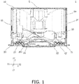
FIG. 1 is a sectional side view schematically showing an overall structure of an air conditioning indoor unit. -
FIG. 2 is a plan view schematically showing the air conditioning indoor unit. -
FIG. 3 is a plan view schematically showing a structure of a part of a blow-out panel of the air conditioning indoor unit. -
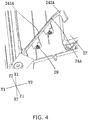
FIG. 4 is a perspective view schematically showing a structure of a part of the blow-out panel of the air conditioning indoor unit. However, an air guide fin is omitted. -
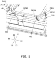
FIG. 5 is a perspective view schematically showing a structure of a part of the blow-out panel of the air conditioning indoor unit. -
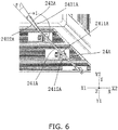
FIG. 6 is a plan view schematically showing a structure of a part of the blow-out panel of the air conditioning indoor unit, and showing a structure near a first connecting rod. -
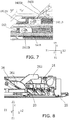
FIG. 7 is a plan view schematically showing the structure of a part of the blow-out panel of the air conditioning indoor unit, and showing a structure near a second connecting rod. -
FIG. 8 is a sectional side view schematically showing a structure of a part of the air conditioning indoor unit. - Hereinafter, an embodiment of a blow-out panel and an air conditioning indoor unit will be described with reference to
FIGS. 1 to 8 taking the air conditioning indoor unit having an indoor unit body and a blow-out panel as an example in a state where the air conditioning indoor unit is actually installed. For convenience of explanation, three directions orthogonal to one another are X direction, Y direction, and Z direction. Among them, the X direction and the Y direction correspond to directions of a horizontal plane when the air conditioning indoor unit is actually installed. The Z direction corresponds to a vertical direction when the air conditioning indoor unit is actually installed. Further, Y1 direction side, Y2 direction side, X1 direction side, X2 direction side, Z1 direction side, and Z2 direction side respectively correspond to a front side, a rear side, a left side, a right side, a lower side, and an upper side when the air conditioning indoor unit is actually installed. - As shown in
FIG. 1 , an air conditioningindoor unit 1 according to this embodiment has anindoor unit body 10 and a blow-outpanel 20. Anaxial fan 30 is provided in theindoor unit body 10. The blow-outpanel 20 is provided at a lower part of the indoor unit body 10 (on the Z1 direction side). - Here, the
indoor unit body 10 has a substantially rectangular parallelepiped shape as a whole, and has a top surface, a bottom surface, and four side surfaces. An intake ports JF are provided on all the side surfaces, and filterunits 40 are provided on all the intake ports JF. As shown inFIG. 1 , aheat exchanger 50 is further provided in theindoor unit body 10. Theheat exchanger 50 is provided at an inner side of the intake ports JF and is surrounded by thefilter units 40. Anaxial fan 30 is provided at an inner side of theheat exchanger 50. Theaxial fan 30 is provided such that an rotational axis overlaps with a center axis L of the blow-out panel 20 (axis that passes through a center of the blow-outpanel 20 and extends in a thickness direction of the blow-out panel 20). As shown inFIG. 2 , at this time, a spiral airflow generated by the axial fan flows clockwise around the center of the blow-out panel. - Further, as shown in
FIGS. 1 and2 , the blow-outpanel 20 has anouter frame 21, aninner frame 22, and a connectingrod 24. A polygonal blow-out port CF is formed by being surrounded by theouter frame 21 and theinner frame 22. The connectingrod 24 is provided at a corner of the blow-outpanel 20 and connects theouter frame 21 and theinner frame 22. This eliminates the need for adding further connecting members, and reduces interference of the other connecting members with the airflow from the blow-out port. Thus, the structure is simple, and furthermore, the blow-out area can be increased. - Here, as shown in
FIGS. 1 and2 , as viewed from an inner surface side to an outer surface side of the blow-outpanel 20, specifically, as viewed from a side of the blow-outpanel 20 closer to the indoor unit body 10 (Z2 direction side) toward a side away from the indoor unit body 10 (Z1 direction side), the connectingrod 24 has a first surface (downstream in a clockwise direction inFIG. 2 ) and a second surface (upstream in the clockwise direction inFIG. 2 ). The airflow generated by the axial fan or the like flows to the second surface and the first surface in that order. In other words, the second surface is an air receiving surface, and the first surface is a surface opposite to the air receiving surface (rear surface). - Here, as shown in
FIG. 2 , the blow-outpanel 20 has a substantially rectangular shape and has the rectangularouter frame 21 and the rectangularinner frame 22. The rectangular blow-out port CF is formed by being surrounded by theouter frame 21 and theinner frame 22. A set ofair guide fins 23 is provided on each side of the blow-out port CF (each side configures a small blow-out port). As shown inFIGS. 2 and 3 , each set ofair guide fins 23 is configured by three parallel air guide fins. Further, each of the three parallel air guide fins are provided such that a length thereof gradually increases along a direction from theinner frame 22 to theouter frame 21 of the blow-outpanel 20. When theair guide fins 23 are rotated to open the blow-out port CF, the airflows at both ends of theair guide fins 23 do not blow out in parallel, but gradually spread downward along the ends of the plurality ofair guide fins 23. Thus, the airflow having a relatively low flow velocity at both ends of theair guide fins 23 is not attracted to a ceiling. This prevents contaminants such as dust included in the airflow from adhering to the ceiling. Further, as a whole, most of the airflow is still guided to theair guide fins 23, and a uniform distribution of the airflow can be maintained unchanged. - As shown in
FIG. 2 , the connectingrod 24 is formed to extend from the center of the blow-outpanel 20 toward the corner of the blow-out port CF as viewed along the Z direction. - Further, as shown in
FIG. 2 , the connectingrod 24 includes a first connectingrod 24A and a second connectingrod 24B provided on one side of the blow-out port. As viewed along the Z direction, the second connectingrod 24B is disposed downstream of the first connectingrod 24A in the clockwise direction. Thus, the airflow generated by the axial fan or the like can be guided to the two corners of the blow-out port CF by using the first connectingrod 24A and the second connectingrod 24B. As a result, both of the airflows at the two corners of the blow-out port CF can be uniformly distributed. - Further, as shown in
FIGS. 2 and6 , the first connectingrod 24A has a connectingrod body 241A and a connectingportion 242A. Theair guide fins 23 are rotatably arranged on the connectingrod body 241A. The connectingportion 242A is closer to the center of the blow-outpanel 20 than the connectingrod body 241A, and connects the connectingrod body 241A to theinner frame 22. Further, as viewed along the Z direction, asecond surface 2421A of the connectingportion 242A and asecond surface 2411A of the connectingrod body 241A are combined to form an inwardly concave shape. Here, as shown inFIGS. 4 and5 , the connectingportion 242A has afirst portion 2423A extending substantially along a direction in which the connectingrod body 241A extends and asecond portion 2424A connecting thefirst portion 2423A to theinner frame 22. Both thefirst portion 2423A and thesecond portion 2424A have an air guide surface that serves to guide the airflow. Specifically, both end surfaces of thefirst portion 2423A and thesecond portion 2424A near the center of the blow-out panel are arch-shaped air guide surfaces. The end surface of thesecond portion 2424A away from the center of the blow-out panel is a beveled surface extending toward the corners of the blow-out port CF (as the end surface goes closer to the corners of the blow-out port CF, the air receiving surface and the rear surface come closer). The beveled surface guides the airflow generated by the axial fan or the like to the corners of the blow-out port CF. - Similarly, as shown in
FIGS. 2 and7 , the second connectingrod 24B has a connectingrod body 241B and a connectingportion 242B.Air guide fins 23 are rotatably arranged on the connectingrod body 241B. The connectingportion 242B is closer to the center of the blow-outpanel 20 than the connectingrod body 241B, and connects the connectingrod body 241B to theinner frame 22. Further, as viewed along the Z direction, asecond surface 2421B of the connectingportion 242B and asecond surface 2411B of the connectingrod body 241B are combined to form an inwardly concave shape. Similarly, as shown inFIG. 5 , the connectingportion 242B has afirst portion 2423B extending substantially along a direction in which the connectingrod body 241B extends and asecond portion 2424B connecting thefirst portion 2423B to theinner frame 22. Both thefirst portion 2423B and thesecond portion 2424B have an air guide surface that serves to guide the airflow. Specifically, both end surfaces of thefirst portion 2423B and thesecond portion 2424B near the central direction of the blow-out panel are arch-shaped air guide surfaces. The end surface of thesecond portion 2424B away from the center of the blow-out panel is a beveled surface extending toward the corners of the blow-out port CF. The beveled surface guides the airflow generated by the axial fan or the like to the corners of the blow-out port CF. - As shown in
FIG. 6 , in the first connectingrod 24A, thesecond surface 2411A as the air receiving surface of the connectingrod body 241A and afirst surface 2412A as the rear surface of the air receiving surface are substantially flat surfaces. Thesecond surface 2421A and thefirst surface 2422A of the connectingportion 242A are substantially flat surfaces. Further, thesecond surface 2411A of the connectingrod body 241A and thesecond surface 2421A of the connectingportion 242A intersect. Thefirst surface 2412A of the connectingrod body 241A and thefirst surface 2422A of the connectingportion 242A are substantially the same surface or form an obtuse angle larger than an angle formed by the second surfaces. - As a result, the airflow guided to an air guide piece can be guided to the
first surface 2412A of the connecting rod body along thefirst surface 2422A of the connectingportion 242A and further to the corners of the blow-out port CF. - Similarly, as shown in
FIG. 7 , in the second connectingrod 24B, thesecond surface 2411B as the air receiving surface of the connectingrod body 241B and afirst surface 2412B as the rear surface of the air receiving surface are substantially flat surfaces. Thesecond surface 2421B and thefirst surface 2422B of the connectingportion 242B are substantially flat surfaces. Further, thesecond surface 2411B of the connectingrod body 241B and thesecond surface 2421B of the connectingportion 242B intersect. Thefirst surface 2412B of the connectingrod body 241B and thefirst surface 2422B of the connectingportion 242B are substantially the same surface, or form a larger obtuse angle than an angle formed by the second surfaces. As a result, the airflow guided to the air guide piece can be guided to thefirst surface 2412B of the connecting rod body along thefirst surface 2422B of the connectingportion 242B and further to the corners of the blow-out port CF. - Further, as shown in
FIGS. 6 and7 , in the first connectingrod 24A, thesecond surface 2421A of the connectingportion 242A and thesecond surface 2411A of the connectingrod body 241A form an obtuse angle. On the second connectingrod 24B, thesecond surface 2421B of the connectingportion 242B and thesecond surface 2411B of the connectingrod body 241B also form an obtuse angle. As a result, when the airflow generated by the axial fan or the like flows toward the connectingrod bodies portions second surfaces portions second surfaces rod bodies - Here, on the first connecting
rod 24A, an angle α1 formed between thesecond surface 2421A of the connectingportion 242A and thesecond surface 2411A of the connectingrod body 241A is preferably 166° or more and 174° or less, and more preferably 171°. On the second connectingrod 24B, an angle α2 formed between thesecond surface 2421B of the connectingportion 242B and thesecond surface 2411B of the connectingrod body 241B is preferably 164° or more and 176° or less, and more preferably 169°. - Further, as shown in
FIGS. 6 and7 , on the first connectingrod 24A, an angle β1 formed between thesecond surface 2421A and thefirst surface 2422A of the connectingportion 242A is preferably larger than 0° and smaller than 10°. The angle β1 is more preferably 6°. On the second connectingrod 24B, an angle β2 formed between thesecond surface 2421B and thefirst surface 2422B of the connectingportion 242B is preferably larger than 0° and smaller than 10°. The angle β2 is more preferably 8.3°. - Further, as shown in
FIG. 2 , the first connectingrod 24A and the second connectingrod 24B on both sides of one corner of the blow-out port CF are formed such that the connecting rod body of the first connectingrod 24A and the connecting rod body of the second connectingrod 24B are parallel to each other. - Further, as shown in
FIG. 4 , on the first connectingrod 24A, a rotatingshaft 29 of theair guide fins 23 is pivotally connected to the connectingrod body 241A in parallel to theair guide fins 23. A boundary between the connectingportion 242A and the connectingrod body 241A is disposed between theinner frame 22 and therotating shaft 29. Similarly, on the second connectingrod 24B, the rotating shaft of theair guide fins 23 is pivotally connected to the connectingrod body 241B in parallel to theair guide fins 23. A boundary between the connectingportion 242B and the connectingrod body 241B is disposed between theinner frame 22 and the rotating shaft. As shown inFIGS. 2 and 3 , theair guide fins 23 provided in the blow-out port CF are pivotally connected to the connectingrod body 241A of the first connectingrod 24A and the connectingrod body 241B of the second connectingrod 24B respectively by one rotating shaft. This enables theair guide fins 23 to be gently rotated. - Here, as shown in
FIGS. 2 and 3 , the blow-outpanel 20 is further provided with an intermediate connectingrod 25. The intermediate connectingrod 25 connects theouter frame 21 to theinner frame 22. The intermediate connectingrod 25 is disposed in a middle of the blow-out port CF and is perpendicular to theair guide fins 23 as viewed along the Y direction. A step motor (not shown) that drives and rotates theair guide fins 23 is attached to the intermediate connectingrod 25. The first connectingrod 24A and the second connectingrod 24B are provided substantially symmetrically to the intermediate connectingrod 25. - Here, as shown in
FIG. 8 , when the air conditioningindoor unit 1 operates, theair guide fins 23 are rotated to a set angle with respect to the outer surface of the blow-outpanel 20. In the thickness direction of the blow-out panel, there is a gap between (an uppermost edge of) theair guide fins 23 and (the connecting rod body of) the connectingrod 24 for the airflow generated by the axial fan to flow. It is preferable that a gap of about 5 mm can be ensured between (the uppermost edge of) theair guide fins 23 and (the connecting rod body of) the connectingrod 24 when theair guide fins 23 are rotated to a maximum angle (for example, 75 degrees or 90 degrees) with respect to the outer surface of the blow-outpanel 20. This gap may be larger than 5 mm in order to expand a path through which the airflow flows, provided that it does not affect a miniaturization of the blow-out panel. This gap may be smaller than 5 mm, provided that it is ensured that theair guide fins 23 do not interfere with the connectingrod 24 after being rotated. - Further, as shown in
FIG. 2 , the blow-outpanel 20 is further provided withair shield plates 27. Theair shield plates 27 are provided at each corner of the blow-out port CF, and connect theouter frame 21 to theinner frame 22. The air shield plates can be used to separate the airflows guided by the air guide fins adjacent in a peripheral direction. This can prevent the airflows guided by the air guide fins adjacent in the peripheral direction from interfering with each other at the blow-out port and improve the airflow at the blow-out port. - Further, as shown in
FIGS. 2 and 3 , theinner frame 22 is provided with acentral member 26. Thecentral member 26 is provided with anair guide piece 261. Theair guide piece 261 has a first surface as a rear surface of an air receiving surface and a second surface as the air receiving surface. As viewed along the Z direction (specifically, the viewpoint ofFIG. 3 ), the first surface is disposed downstream of the second surface in the clockwise direction. Further, anintake end 261a of theair guide piece 261 is disposed on an extension line of the first surface of the connecting rod body of the connectingrod 24. Specifically, the intake end of the air guide piece disposed between the intermediate connectingrod 25 and the first connectingrod 24A is disposed on an extension line of the rear surface (first surface) of the air receiving surface of the connecting rod body of the first connectingrod 24A. The intake end of the air guide piece disposed between the intermediate connectingrod 25 and the second connectingrod 24B is disposed on an extension line of the first surface of the connecting rod body of the second connectingrod 24B. - Further, as shown in
FIG. 8 , at least part of thecentral member 26 projects from the blow-outpanel 20 in the Z direction such that theair guide piece 261 can be easily installed on thecentral member 26. Thecentral member 26, which has the arch-shaped air guide surface, can guide the airflow generated by the axial fan or the like to the blow-out port CF. Further, as shown inFIG. 8 , the connectingrod 24 is disposed at a center of theair guide piece 261 in the Z direction. The airflow generated by the axial fan or the like flows to the connecting portion of the connectingrod 24 via the air receiving surface of theair guide piece 261, and is guided to the corners of the blow-out port CF along the connecting rod body. - In this embodiment, when the air conditioning
indoor unit 1 operates, theaxial fan 30 is rotated and theair guide fins 23 of the blow-outpanel 20 open at a predetermined angle. The airflow is sucked into theindoor unit body 10 from the intake port JF by a function of theaxial fan 30, passes through thefilter unit 40 and theheat exchanger 50 in that order, and flows toward a center of the air conditioningindoor unit 1. Next, the airflow forms a spiral airflow through theaxial fan 30 and flows down below to thecentral member 26. Then, the airflow is guided to the arch-shaped air guide surface of thecentral member 26, spreads from the center of the blow-outpanel 20 to the periphery, and reaches the blow-out port CF. A part of this airflow is guided to the corners of the blow-out port CF by theair guide piece 261 provided on thecentral member 26, specifically, the second surface as the air receiving surface of theair guide piece 261. This part of the airflow passes from below a support rod 262 (thissupport rod 262 connects thecentral member 26 and the indoor unit body 10), and is guided to the corners of the blow-out port CF via the connectingrod 24. Specifically, the airflow flows along the connectingportions rod 24 to the connectingrod bodies central member 26 to the center of the blow-out port. Finally, the airflow passes through the blow-out port CF, is guided to theair guide fins 23 of the blow-out port CF, and is blown out of the air conditioningindoor unit 1. - In the air conditioning
indoor unit 1 according to this embodiment, the blow-outpanel 20 uses the polygonal blow-out port CF formed by being surrounded by theouter frame 21 and theinner frame 22. This enables the air to be blown out all around 360°. Further, the blow-outpanel 20 has the connectingrod 24 provided at the corners of the blow-outpanel 20. As viewed along the Z direction, the second surface of the connecting portion of the connectingrod 24 and the second surface of the connecting rod body are combined to form an inwardly concave shape. Thus, the second surface of the connecting portion of the connectingrod 24 is used to guide the airflow generated by theaxial fan 30 to the corners of the blow-out port CF via the second surface of the connecting rod body. This allows the air to be blown out of the blow-out port CF uniformly. - Further, in the air conditioning
indoor unit 1 according to this embodiment, on the connectingrod 24, the second surface of the connecting portion and the second surface of the connecting rod body form an inwardly indented obtuse angle. This ensures an effect that the second surface of the connecting portion of the connectingrod 24 guides the airflow generated by theaxial fan 30 to the corners of the blow-out port CF. In addition, it is possible to reduce the interference of the connecting portion of the connectingrod 24 and the connecting rod body with the airflow generated by theaxial fan 30 and to make the air blown out of the blow-out port CF uniform. - Further, in the air conditioning
indoor unit 1 of this embodiment, the connectingrod 24 includes the first connectingrod 24A and the second connectingrod 24B. On the first connectingrod 24A, the angle formed between thesecond surface 2421A of the connectingportion 242A and thesecond surface 2411A of the connectingrod body 241A is 166° or more and 174° or less, and the angle formed by thesecond surface 2421A and thefirst surface 2422A of the connectingportion 242A is more than 0° and less than 10°. On the second connectingrod 24B, the angle formed between thesecond surface 2421B of the connectingportion 242B and thesecond surface 2411B of the connectingrod body 241B is 164° or more and 176° or less, and the angle formed by thesecond surface 2421B and thefirst surface 2422B of the connectingportion 242B is more than 0° and less than 10°. This further ensures the effect that the second surface of the connecting portion of the connectingrod 24 guides the airflow generated by theaxial fan 30. In addition, it is possible to reduce the interference of the connecting portion of the connectingrod 24 and the connecting rod body with the airflow generated by theaxial fan 30 and to make the airflow blown out of the blow-out port CF more uniform. This enables the air to be blown out all around 360° of the blow-out panel. - Further, in the air conditioning
indoor unit 1 according to this embodiment, the first connectingrod 24A and the second connectingrod 24B on both sides of one corner of the blow-out port CF are formed such that the connecting rod body of the first connectingrod 24A and the connecting rod body of the second connectingrod 24B are parallel to each other. This can simplify the entire structure of the blow-outpanel 20. In addition, it is possible to reduce the interference of the connecting rod body of the connectingrod 24 with the airflow at the corners of the blow-out port CF and to make the air blown out of the blow-out port CF uniform. - Further, in the air conditioning
indoor unit 1 according to this embodiment, on the connectingrod 24, the end of the connecting portion away from the connecting rod body has an arched shape as viewed along the Z direction. This can reduce the interference of the end of the connecting portion of the connectingrod 24 away from the connecting rod body with the airflow generated by theaxial fan 30. Then, the arched shape of the end is used to guide the airflow generated by the axial fan or the like to the blow-out port CF, and the air is thus blown out of the blow-out port CF uniformly. - Further, in the air conditioning
indoor unit 1 according to this embodiment, on the connectingrod 24, a width of the connecting portion becomes gradually narrower toward the connecting rod body as viewed along the Z direction. This can ensure a strength of the entire connectingrod 24 and reduce a volume of the connectingrod 24. Thus, it is possible to reduce the interference of the connecting portion of the connectingrod 24 with the airflow generated by theaxial fan 30 and to make the air blown out of the blow-out port CF uniform. - Further, in the air conditioning
indoor unit 1 according to this embodiment, the connectingrod 24 is formed to extend from a central direction of the blow-outpanel 20 toward the corners of the blow-out port CF as viewed along the Z direction. This can reduce the interference of the connectingrod 24 with the airflow generated by theaxial fan 30 and also allows the airflow to blow out from the corners of the blow-out port CF. Furthermore, the air is blown out all around 360° of the blow-out panel, and the air blown out of the blow-out port CF is uniform. - Further, in the air conditioning
indoor unit 1 according to this embodiment, on the connectingrod 24, the width of the connecting portion is equal to or greater than a width of the connecting rod body as viewed along the Z direction. It is therefore possible to reduce the interference of the connectingrod 24 with the airflow generated by theaxial fan 30 and to make the air blown out of the blow-out port CF uniform. - Further, in the air conditioning
indoor unit 1 according to this embodiment, on the connectingrod 24, the connecting rod body is connected to theair guide fins 23 via the rotatingshaft 29. This enables theair guide fins 23 to be connected to the connectingrod 24 with a simple structure. - Further, in the air conditioning
indoor unit 1 according to this embodiment, on the connectingrod 24, the boundary between the connecting portion and the connecting rod body is disposed between theinner frame 22 and therotating shaft 29. This simplifies the structure of the connectingrod 24 and can prevent theair guide fins 23 from interfering with the connectingrod 24 during rotation of theair guide fins 23. - In the air conditioning
indoor unit 1 according to this embodiment, the blow-outpanel 20 is further provided with the intermediate connectingrod 25. The intermediate connectingrod 25 connects theouter frame 21 to theinner frame 22. As viewed along the Z direction, the intermediate connectingrod 25 is disposed in the middle of the blow-out port CF and is perpendicular to theair guide fins 23. A step motor that drives and rotates theair guide fins 23 is attached to the intermediate connectingrod 25. As a result, the force received by theair guide fins 23 can be balanced and a drive structure can be simplified. Furthermore, a step motor can be provided in the frame outside of the blow-out port and the blow-out panel can be miniaturized. - Further, in the air conditioning
indoor unit 1 according to this embodiment, theinner frame 22 is provided with thecentral member 26. Thecentral member 26 is provided with theair guide piece 261. Accordingly, theair guide piece 261 is used to guide the airflow generated by theaxial fan 30 and to prevent the airflow from blowing straight downward. This enables the air to be blown out of the blow-out port CF more uniformly. - Further, in the air conditioning
indoor unit 1 according to this embodiment, theintake end 261a of theair guide piece 261 is disposed on an extension line of the first surface of the connecting rod body of the connecting rod. This further ensures the airflow flowing to the corners of the blow-out port CF and allows the air to be blown out of the blow-out port CF uniformly. - Further, in the air conditioning
indoor unit 1 according to this embodiment, at least a part of thecentral member 26 projects from the blow-outpanel 20 in the Z direction. Thus, an interaction between theair guide piece 261 and the connectingrod 24 further ensures the airflow flowing to the corners of the blow-out port CF and allows the air to be blown out of the blow-out port CF uniformly. - Further, in the air conditioning
indoor unit 1 according to this embodiment, the connectingrod 24 is disposed at the center of theair guide piece 261 in the Z direction. This strengthens the interaction between theair guide piece 261 and the connectingrod 24, ensures the airflow flowing to the corners of the blow-out port CF, and allows the air to be blown out of the blow-out port CF uniformly. - Although the blow-out
panel 20 and the air conditioningindoor unit 1 have been described as an example with reference to the drawings, the specific implementation of the present invention is obviously not limited to the above embodiment. - For example, in the above embodiment, the air conditioning indoor unit including the indoor unit body and the blow-out panel provided at the lower part of the indoor unit body has been described as an example. However, the present invention is not limited thereto. For example, the blow-out panel may be connected to an air treatment device through a blower tube, and the spiral airflow sent from a blower unit of the air treatment device may be sent to the blow-out panel via the blower tube and then sent out of the blow-out panel.
- Further, in the above embodiment, the spiral airflow generated by the axial fan flows clockwise around the center of the blow-out panel. However, the spiral airflow generated by the axial fan may flow counterclockwise around the center of the blow-out panel by driving of a motor. In this way, as viewed from the inner surface side to the outer surface side of the blow-out panel, the first surface of the connecting portion and the connecting rod body is disposed downstream of the second surface in the counterclockwise direction around the center of the blow-out panel. The second connecting rod is disposed downstream of the first connecting rod in the counterclockwise direction around the center of the blow-out panel. The first surface of the air guide piece is disposed downstream of the second surface of the air guide piece in the counterclockwise direction around the center of the blow-out panel. Compared to the above embodiment, the structure of this blow-out panel and the structure of the blow-out panel of the above embodiment are mirror images of each another.
- Further, the
indoor unit body 10 has a substantially cubic shape as a whole in the above embodiment. However, the shape of the indoor unit body may be appropriately changed depending on the situation. For example, the indoor unit body may be formed to be in a substantially columnar shape or a prismatic shape other than a square prism. Similarly, although the blow-outpanel 20 has a substantially rectangular shape as viewed along the Z direction in the above embodiment, the shape of the blow-out panel may be appropriately changed depending on the situation. For example, the blow-out panel may be formed in a substantially circular shape or, for example, a polygon other than a quadrangle as viewed along the Z direction. - Further, the blow-out port CF has a rectangular shape in the above embodiment, but not limited to this as long as the blow-out port is formed in a polygonal shape.
- Further, in the above embodiment, the intake ports JF are provided on all the side surfaces of the
indoor unit body 10, and thefilter units 40 are provided on all the intake ports JF. However, the numbers of intake ports and filter units may be appropriately adjusted as necessary. - Further, one first connecting
rod 24A and one second connectingrod 24B are provided on one side of the blow-out port CF in the above embodiment. However, the numbers of first connectingrods 24A and second connectingrods 24B provided on the one side of the blow-out port CF may be changed as required. - Further, the connecting
rod 24 includes the first connectingrod 24A and the second connectingrod 24B in the above embodiment. However, the connectingrod 24 is not limited to this, and may include only one of the first connectingrod 24A or the second connectingrod 24B. - Further, in the above embodiment, the first connecting
rod 24A and the second connectingrod 24B on both sides of one corner of the blow-out port CF are formed such that the connecting rod body of the first connectingrod 24A and the connecting rod body of the second connectingrod 24B are in parallel to each other. However, without being limited to this, the connecting rod body of the first connectingrod 24A and the connecting rod body of the second connectingrod 24B are provided symmetrically to the intermediate connectingrod 25, but may be formed non-parallel to each other. - Further, at least a part of the
central member 26 projects from the blow-outpanel 20 in the above embodiment. However, the present invention is not limited to this. In the thickness direction of the blow-out panel, an uppermost part of the central member may have substantially the same height as an uppermost part of the blow-out panel or may be lower than the uppermost part of the blow-out panel. - Further, in the above embodiment, on the first connecting
rod 24A, thesecond surface 2411A and thefirst surface 2412A of the connectingrod body 241A are substantially flat surfaces, and thesecond surface 2421A and thefirst surface 2422A of the connectingportion 242A are substantially flat surfaces. On the second connectingrod 24B, thesecond surface 2411B and thefirst surface 2412B of the connectingrod body 241B are substantially flat surfaces, and thesecond surface 2421B and thefirst surface 2422B of the connectingportion 242B are substantially flat surfaces. However, without being limited to this, thesecond surface 2411A and thefirst surface 2412A of the connectingrod body 241A, and thesecond surface 2421A and thefirst surface 2422A of the connectingportion 242A may be formed in another shape (for example, an arch, a folded line, or the like as viewed along the Z direction). Thesecond surface 2411B and thefirst surface 2412B of the connectingrod body 241B, and thesecond surface 2421B and thefirst surface 2422B of the connectingportion 242B may also be formed in another shape (for example, an arch, a folded line, or the like as viewed along the Z direction). - Further, the
central member 26 is provided on theinner frame 22 in the above embodiment, but the present invention is not limited to this, and the central member may be omitted. -
- 1
- Air conditioning indoor unit
- 10
- Indoor unit body
- 20
- Blow-out panel
- 21
- Outer frame
- 22
- Inner frame
- 23
- Air guide fin
- 24
- Connecting rod
- 24A
- First connecting rod
- 24B
- Second connecting rod
- 241A, 241B
- Connecting rod body
- 2411A, 2411B
- Second surface
- 2412A, 2412B
- First surface
- 242A, 242B
- Connecting portion
- 2421A, 2421B
- Second surface
- 2422A, 2422B
- First surface
- 2423A, 2423B
- First portion of connecting portion
- 2424A, 2424B
- Second portion of connecting portion
- XMA, XMB
- Beveled surface
- 25
- Intermediate connecting rod
- 26
- Central member
- 261
- Air guide piece
- 261a
- Intake end
- 262
- Support rod
- 27
- Air shield plate
- 29
- Rotating shaft
- 30
- Axial fan
- 40
- Filter unit
- 50
- Heat exchanger
- L
- Center axis
Claims (20)
- A blow-out panel (20) comprising:an outer frame (21);an inner frame (22); anda connecting rod (24), whereina blow-out port (CF) having a polygonal shape is formed by being surrounded by the outer frame (21) and the inner frame (22),the connection rod is provided at a corner of the blow-out port (CF),the connecting rod (24) connects the outer frame and the inner frame,the connecting rod (24) has a connecting rod body (241A, 241B) and a connecting portion (242A, 242B),the connecting portion (242A, 242B) is closer to a center of the blow-out panel (20) than the connecting rod body (241A, 241B),the connecting portion (242A, 242B) connects the connecting rod body (241A, 241B) to the inner frame (22),the connecting portion (242A, 242B) and the connecting rod body (241A, 241B) each have a first surface and a second surface,as viewed from an inner surface side to an outer surface side of the blow-out panel (20), the first surface is disposed downstream of the second surface in a clockwise direction around the center of the blow-out panel (20), or the first surface is disposed downstream of the second surface in a counterclockwise direction around the center of the blow-out panel (20), andthe second surface (2421A, 2421B) of the connecting portion (242A, 242B) and the second surface (2411A, 2411B) of the connecting rod body (241A, 241B) are combined to form an inwardly concave shape.
- The blow-out panel according to claim 1, wherein the second surface (2421A, 2421B) of the connecting portion (242A, 242B) and the second surface (2411A, 2411B) of the connecting rod body (241A, 241B) form an obtuse angle.
- The blow-out panel according to claim 2, whereinthe connecting rod (24) includes a first connecting rod (24A) and a second connecting rod (24B) that are provided on one side of the blow-out port (CF), andas viewed from an inner surface side to an outer surface side of the blow-out panel (20), the first surface is disposed downstream of the second surface in a clockwise direction around a center of the blow-out panel (20), and the second connecting rod (24B) is disposed downstream of the first connecting rod (24A) in the clockwise direction, orthe first surface is disposed downstream of the second surface in a direction counterclockwise around the center of the blow-out panel (20), and the second connecting rod (24B) is disposed downstream of the first connecting rod (24A) in the counterclockwise direction.
- The blow-out panel according to claim 3, whereinon the first connecting rod (24A), an angle formed between the second surface (2421A) of the connecting portion (242A) and the second surface (2411A) of the connecting rod body (241A) is 166° or more and 174° or less, and/oron the second connecting rod (24B), an angle formed between the second surface (2421B) of the connecting portion (242B) and the second surface (2411B) of the connecting rod body (241B) is 164° or more and 176° or less.
- The blow-out panel according to claim 4, whereinon the first connecting rod (24A), an angle formed between the second surface (2421A) and a first surface (2422A) of the connecting portion (242A) is more than 0° and less than 10°, and/oron the second connecting rod (24B), an angle formed between the second surface (2421B) and a first surface (2422B) of the connecting portion (242B) is more than 0° and less than 10°.
- The blow-out panel according to any one of claims 1 to 5, wherein an end of the connecting portion (242A, 242B) away from the connecting rod body (241A, 241B) has an arch shape as viewed from the inner surface side to the outer surface side of the blow-out panel (20).
- The blow-out panel according to any one of claims 1 to 6, wherein a width of the connecting portion (242A, 242B) gradually narrows toward the connecting rod body (241A, 241B) as viewed from the inner surface side to the outer surface side of the blow-out panel (20).
- The blow-out panel according to any one of claims 1 to 7, wherein the connecting rod (24) is formed to extend from the center of the blow-out panel (20) toward the corner of the blow-out port (CF) as viewed from the inner surface side to the outer surface side of the blow-out panel (20).
- The blow-out panel according to any one of claims 1 to 8, wherein the width of the connecting portion (242A, 242B) is bigger than a width of the connecting rod body (241A, 241B) as viewed from the inner surface side to the outer surface side of the blow-out panel (20).
- The blow-out panel according to any one of claims 1 to 9, further comprising an air guide fin (23) provided at the blow-out port (CF), wherein the air guide fin (23) is rotatably arranged on the connecting rod body (241A, 241B).
- The blow-out panel according to claim 10, wherein a rotating shaft (29) of the air guide fin (23) is pivotally connected to the connecting rod body (241A, 241B) in parallel to the air guide fin (23).
- The blow-out panel according to claim 11, wherein a boundary between the connecting portion (242A, 242B) and the connecting rod body (241A, 241B) is disposed between the inner frame (22) and the rotating shaft (29).
- The blow-out panel according to claim 10, further comprising an intermediate connecting rod (25), whereinthe intermediate connecting rod (25) connects the outer frame (21) to the inner frame (22),the intermediate connecting rod (25) is disposed in a middle of the blow-out port (CF) and is perpendicular to the air guide fin (23) as viewed from an inner surface side to an outer surface side of the blow-out panel (20), anda step motor that drives and rotates the air guide fin (23) is attached to the intermediate connecting rod (25).
- The blow-out panel according to any one of claims 1 to 13, whereinthe inner frame (22) is provided with a central member (26), andthe central member (26) is provided with an air guide piece (261).
- The blow-out panel according to claim 14, wherein an intake end (261a) of the air guide piece (261) is on an extension line of the first surface (2412A, 2412B) of the connecting rod body (241A, 241B).
- The blow-out panel according to claim 14 or 15, wherein the connecting rod (24) is disposed at a center of the air guide piece (261) in a thickness direction of the blow-out panel (20).
- The blow-out panel according to any one of claims 1 to 16, whereinthe connecting portion (242A, 242B) has a first portion (2423A, 2423B) extending along a direction in which the connecting rod body (241A, 241B) extends, and a second portion connecting the first portion to the inner frame (2424A, 2424B), andan end surface of the second portion away from the center of the blow-out panel (20) is a beveled surface extending toward the corner of the blow-out port (CF).
- An air conditioning indoor unit comprising:an indoor unit body (10); andthe blow-out panel (20) described in any one of claims 1 to 17,wherein the blow-out panel (20) is provided at a lower part of the indoor unit body (10) or is connected to the indoor unit body (10) via a blower tube.
- The air conditioning indoor unit according to claim 18, whereinan axial fan (30) is provided in the indoor unit body (10),a center of the axial fan (30) and a center of the blow-out panel (20) overlap as viewed along a thickness direction of the blow-out panel (20),the inner frame (22) is provided with a central member (26),the central member (26) is provided with an air guide piece (261), andan airflow blown out from the axial fan (30) flows to a connecting portion (242A, 242B) of the connecting rod (24) via the air guide piece (261).
- The air conditioning indoor unit according to claim 19, whereinthe air guide piece (261) has a first surface and a second surface,as viewed from an inner surface side to an outer surface side of the blow-out panel (20), the airflow blown out from the axial fan (30) flows clockwise around the center of the blow-out panel (20), and the first surface is disposed downstream of the second surface in a clockwise direction, orthe airflow blown out from the axial fan (30) flows counterclockwise around the center of the blow-out panel (20), and the first surface is disposed downstream of the second surface in a counterclockwise direction, andthe airflow blown out from the axial fan (30) flows to the connecting portion (242A, 242B) of the connecting rod (24) via the second surface of the air guide piece (261).
Applications Claiming Priority (3)
| Application Number | Priority Date | Filing Date | Title |
|---|---|---|---|
| CN201711408365.8A CN109974270B (en) | 2017-12-22 | 2017-12-22 | Air outlet panel and air conditioner indoor unit |
| CN201721818918.2U CN207975820U (en) | 2017-12-22 | 2017-12-22 | Wind outlet panel and air conditioner indoor unit |
| PCT/JP2018/044915 WO2019124097A1 (en) | 2017-12-22 | 2018-12-06 | Blowout panel and air conditioning indoor unit |
Publications (3)
| Publication Number | Publication Date |
|---|---|
| EP3730859A1 true EP3730859A1 (en) | 2020-10-28 |
| EP3730859A4 EP3730859A4 (en) | 2021-01-27 |
| EP3730859B1 EP3730859B1 (en) | 2022-01-19 |
Family
ID=66994294
Family Applications (1)
| Application Number | Title | Priority Date | Filing Date |
|---|---|---|---|
| EP18890942.8A Active EP3730859B1 (en) | 2017-12-22 | 2018-12-06 | Blowout panel and air conditioning indoor unit |
Country Status (3)
| Country | Link |
|---|---|
| EP (1) | EP3730859B1 (en) |
| JP (1) | JP6756410B2 (en) |
| WO (1) | WO2019124097A1 (en) |
Family Cites Families (4)
| Publication number | Priority date | Publication date | Assignee | Title |
|---|---|---|---|---|
| ES2808349T3 (en) * | 2011-06-09 | 2021-02-26 | Mitsubishi Electric Corp | Indoor unit for air conditioner |
| JP6439537B2 (en) * | 2015-03-26 | 2018-12-19 | 株式会社富士通ゼネラル | Embedded ceiling air conditioner |
| CN207132442U (en) * | 2017-06-23 | 2018-03-23 | 大金工业株式会社 | Indoor apparatus of air conditioner |
| CN207132538U (en) * | 2017-06-23 | 2018-03-23 | 大金工业株式会社 | Wind outlet panel and indoor apparatus of air conditioner |
-
2018
- 2018-12-06 JP JP2019560954A patent/JP6756410B2/en active Active
- 2018-12-06 EP EP18890942.8A patent/EP3730859B1/en active Active
- 2018-12-06 WO PCT/JP2018/044915 patent/WO2019124097A1/en not_active Ceased
Also Published As
| Publication number | Publication date |
|---|---|
| EP3730859B1 (en) | 2022-01-19 |
| JP6756410B2 (en) | 2020-09-16 |
| EP3730859A4 (en) | 2021-01-27 |
| WO2019124097A1 (en) | 2019-06-27 |
| JPWO2019124097A1 (en) | 2020-09-24 |
Similar Documents
| Publication | Publication Date | Title |
|---|---|---|
| JP3972894B2 (en) | Air conditioner | |
| AU2010316385B2 (en) | Indoor unit of air conditioning apparatus | |
| WO2005052464A1 (en) | Air conditioner | |
| ES2568039T3 (en) | Indoor unit | |
| JP5012260B2 (en) | Duct fan | |
| JP5338895B2 (en) | Air conditioning indoor unit | |
| CN103175291A (en) | Indoor unit of air-conditioning apparatus | |
| WO2013099896A1 (en) | Air conditioner indoor unit | |
| JPWO2017134762A1 (en) | Air conditioner indoor unit | |
| JP6078777B2 (en) | Air purifier | |
| EP3730859B1 (en) | Blowout panel and air conditioning indoor unit | |
| JP2021109459A (en) | Air conditioner air outlet device | |
| JP2005024225A (en) | Air conditioner | |
| EP3730860B1 (en) | Blow-out panel, and air conditioning indoor unit | |
| JP3521813B2 (en) | Air conditioner | |
| JP4863696B2 (en) | Ventilation equipment | |
| EP3348930A1 (en) | Wall mounting air-conditioning indoor unit | |
| JP6182851B2 (en) | Air conditioning indoor unit | |
| JP2018200254A (en) | Environmental test equipment and heat treatment equipment | |
| JP6437116B2 (en) | Air conditioner indoor unit | |
| CN207975820U (en) | Wind outlet panel and air conditioner indoor unit | |
| JP2004257674A (en) | Air conditioner | |
| JP2018165589A (en) | Indoor unit of ceiling embedded type air conditioner | |
| JP2016183802A (en) | Air purifier | |
| KR100517625B1 (en) | Picture frame type air conditioner and therefor control process |
Legal Events
| Date | Code | Title | Description |
|---|---|---|---|
| STAA | Information on the status of an ep patent application or granted ep patent |
Free format text: STATUS: THE INTERNATIONAL PUBLICATION HAS BEEN MADE |
|
| PUAI | Public reference made under article 153(3) epc to a published international application that has entered the european phase |
Free format text: ORIGINAL CODE: 0009012 |
|
| STAA | Information on the status of an ep patent application or granted ep patent |
Free format text: STATUS: REQUEST FOR EXAMINATION WAS MADE |
|
| 17P | Request for examination filed |
Effective date: 20200715 |
|
| AK | Designated contracting states |
Kind code of ref document: A1 Designated state(s): AL AT BE BG CH CY CZ DE DK EE ES FI FR GB GR HR HU IE IS IT LI LT LU LV MC MK MT NL NO PL PT RO RS SE SI SK SM TR |
|
| AX | Request for extension of the european patent |
Extension state: BA ME |
|
| A4 | Supplementary search report drawn up and despatched |
Effective date: 20210114 |
|
| RIC1 | Information provided on ipc code assigned before grant |
Ipc: F24F 1/0029 20190101ALI20201223BHEP Ipc: F24F 1/0011 20190101ALI20201223BHEP Ipc: F24F 13/20 20060101AFI20201223BHEP Ipc: F24F 1/0047 20190101ALI20201223BHEP Ipc: F24F 13/075 20060101ALI20201223BHEP |
|
| DAV | Request for validation of the european patent (deleted) | ||
| DAX | Request for extension of the european patent (deleted) | ||
| GRAP | Despatch of communication of intention to grant a patent |
Free format text: ORIGINAL CODE: EPIDOSNIGR1 |
|
| STAA | Information on the status of an ep patent application or granted ep patent |
Free format text: STATUS: GRANT OF PATENT IS INTENDED |
|
| INTG | Intention to grant announced |
Effective date: 20210916 |
|
| GRAS | Grant fee paid |
Free format text: ORIGINAL CODE: EPIDOSNIGR3 |
|
| GRAA | (expected) grant |
Free format text: ORIGINAL CODE: 0009210 |
|
| STAA | Information on the status of an ep patent application or granted ep patent |
Free format text: STATUS: THE PATENT HAS BEEN GRANTED |
|
| AK | Designated contracting states |
Kind code of ref document: B1 Designated state(s): AL AT BE BG CH CY CZ DE DK EE ES FI FR GB GR HR HU IE IS IT LI LT LU LV MC MK MT NL NO PL PT RO RS SE SI SK SM TR |
|
| REG | Reference to a national code |
Ref country code: GB Ref legal event code: FG4D |
|
| REG | Reference to a national code |
Ref country code: CH Ref legal event code: EP |
|
| REG | Reference to a national code |
Ref country code: DE Ref legal event code: R096 Ref document number: 602018029918 Country of ref document: DE |
|
| REG | Reference to a national code |
Ref country code: AT Ref legal event code: REF Ref document number: 1464021 Country of ref document: AT Kind code of ref document: T Effective date: 20220215 |
|
| REG | Reference to a national code |
Ref country code: IE Ref legal event code: FG4D |
|
| REG | Reference to a national code |
Ref country code: LT Ref legal event code: MG9D |
|
| REG | Reference to a national code |
Ref country code: NL Ref legal event code: MP Effective date: 20220119 |
|
| REG | Reference to a national code |
Ref country code: AT Ref legal event code: MK05 Ref document number: 1464021 Country of ref document: AT Kind code of ref document: T Effective date: 20220119 |
|
| PG25 | Lapsed in a contracting state [announced via postgrant information from national office to epo] |
Ref country code: NL Free format text: LAPSE BECAUSE OF FAILURE TO SUBMIT A TRANSLATION OF THE DESCRIPTION OR TO PAY THE FEE WITHIN THE PRESCRIBED TIME-LIMIT Effective date: 20220119 |
|
| PG25 | Lapsed in a contracting state [announced via postgrant information from national office to epo] |
Ref country code: SE Free format text: LAPSE BECAUSE OF FAILURE TO SUBMIT A TRANSLATION OF THE DESCRIPTION OR TO PAY THE FEE WITHIN THE PRESCRIBED TIME-LIMIT Effective date: 20220119 Ref country code: RS Free format text: LAPSE BECAUSE OF FAILURE TO SUBMIT A TRANSLATION OF THE DESCRIPTION OR TO PAY THE FEE WITHIN THE PRESCRIBED TIME-LIMIT Effective date: 20220119 Ref country code: PT Free format text: LAPSE BECAUSE OF FAILURE TO SUBMIT A TRANSLATION OF THE DESCRIPTION OR TO PAY THE FEE WITHIN THE PRESCRIBED TIME-LIMIT Effective date: 20220519 Ref country code: NO Free format text: LAPSE BECAUSE OF FAILURE TO SUBMIT A TRANSLATION OF THE DESCRIPTION OR TO PAY THE FEE WITHIN THE PRESCRIBED TIME-LIMIT Effective date: 20220419 Ref country code: LT Free format text: LAPSE BECAUSE OF FAILURE TO SUBMIT A TRANSLATION OF THE DESCRIPTION OR TO PAY THE FEE WITHIN THE PRESCRIBED TIME-LIMIT Effective date: 20220119 Ref country code: HR Free format text: LAPSE BECAUSE OF FAILURE TO SUBMIT A TRANSLATION OF THE DESCRIPTION OR TO PAY THE FEE WITHIN THE PRESCRIBED TIME-LIMIT Effective date: 20220119 Ref country code: ES Free format text: LAPSE BECAUSE OF FAILURE TO SUBMIT A TRANSLATION OF THE DESCRIPTION OR TO PAY THE FEE WITHIN THE PRESCRIBED TIME-LIMIT Effective date: 20220119 Ref country code: BG Free format text: LAPSE BECAUSE OF FAILURE TO SUBMIT A TRANSLATION OF THE DESCRIPTION OR TO PAY THE FEE WITHIN THE PRESCRIBED TIME-LIMIT Effective date: 20220419 |
|
| PG25 | Lapsed in a contracting state [announced via postgrant information from national office to epo] |
Ref country code: PL Free format text: LAPSE BECAUSE OF FAILURE TO SUBMIT A TRANSLATION OF THE DESCRIPTION OR TO PAY THE FEE WITHIN THE PRESCRIBED TIME-LIMIT Effective date: 20220119 Ref country code: LV Free format text: LAPSE BECAUSE OF FAILURE TO SUBMIT A TRANSLATION OF THE DESCRIPTION OR TO PAY THE FEE WITHIN THE PRESCRIBED TIME-LIMIT Effective date: 20220119 Ref country code: GR Free format text: LAPSE BECAUSE OF FAILURE TO SUBMIT A TRANSLATION OF THE DESCRIPTION OR TO PAY THE FEE WITHIN THE PRESCRIBED TIME-LIMIT Effective date: 20220420 Ref country code: FI Free format text: LAPSE BECAUSE OF FAILURE TO SUBMIT A TRANSLATION OF THE DESCRIPTION OR TO PAY THE FEE WITHIN THE PRESCRIBED TIME-LIMIT Effective date: 20220119 Ref country code: AT Free format text: LAPSE BECAUSE OF FAILURE TO SUBMIT A TRANSLATION OF THE DESCRIPTION OR TO PAY THE FEE WITHIN THE PRESCRIBED TIME-LIMIT Effective date: 20220119 |
|
| PG25 | Lapsed in a contracting state [announced via postgrant information from national office to epo] |
Ref country code: IS Free format text: LAPSE BECAUSE OF FAILURE TO SUBMIT A TRANSLATION OF THE DESCRIPTION OR TO PAY THE FEE WITHIN THE PRESCRIBED TIME-LIMIT Effective date: 20220519 |
|
| REG | Reference to a national code |
Ref country code: DE Ref legal event code: R097 Ref document number: 602018029918 Country of ref document: DE |
|
| PG25 | Lapsed in a contracting state [announced via postgrant information from national office to epo] |
Ref country code: SM Free format text: LAPSE BECAUSE OF FAILURE TO SUBMIT A TRANSLATION OF THE DESCRIPTION OR TO PAY THE FEE WITHIN THE PRESCRIBED TIME-LIMIT Effective date: 20220119 Ref country code: SK Free format text: LAPSE BECAUSE OF FAILURE TO SUBMIT A TRANSLATION OF THE DESCRIPTION OR TO PAY THE FEE WITHIN THE PRESCRIBED TIME-LIMIT Effective date: 20220119 Ref country code: RO Free format text: LAPSE BECAUSE OF FAILURE TO SUBMIT A TRANSLATION OF THE DESCRIPTION OR TO PAY THE FEE WITHIN THE PRESCRIBED TIME-LIMIT Effective date: 20220119 Ref country code: EE Free format text: LAPSE BECAUSE OF FAILURE TO SUBMIT A TRANSLATION OF THE DESCRIPTION OR TO PAY THE FEE WITHIN THE PRESCRIBED TIME-LIMIT Effective date: 20220119 Ref country code: DK Free format text: LAPSE BECAUSE OF FAILURE TO SUBMIT A TRANSLATION OF THE DESCRIPTION OR TO PAY THE FEE WITHIN THE PRESCRIBED TIME-LIMIT Effective date: 20220119 Ref country code: CZ Free format text: LAPSE BECAUSE OF FAILURE TO SUBMIT A TRANSLATION OF THE DESCRIPTION OR TO PAY THE FEE WITHIN THE PRESCRIBED TIME-LIMIT Effective date: 20220119 |
|
| PLBE | No opposition filed within time limit |
Free format text: ORIGINAL CODE: 0009261 |
|
| STAA | Information on the status of an ep patent application or granted ep patent |
Free format text: STATUS: NO OPPOSITION FILED WITHIN TIME LIMIT |
|
| PG25 | Lapsed in a contracting state [announced via postgrant information from national office to epo] |
Ref country code: AL Free format text: LAPSE BECAUSE OF FAILURE TO SUBMIT A TRANSLATION OF THE DESCRIPTION OR TO PAY THE FEE WITHIN THE PRESCRIBED TIME-LIMIT Effective date: 20220119 |
|
| 26N | No opposition filed |
Effective date: 20221020 |
|
| PG25 | Lapsed in a contracting state [announced via postgrant information from national office to epo] |
Ref country code: SI Free format text: LAPSE BECAUSE OF FAILURE TO SUBMIT A TRANSLATION OF THE DESCRIPTION OR TO PAY THE FEE WITHIN THE PRESCRIBED TIME-LIMIT Effective date: 20220119 |
|
| P01 | Opt-out of the competence of the unified patent court (upc) registered |
Effective date: 20230525 |
|
| PG25 | Lapsed in a contracting state [announced via postgrant information from national office to epo] |
Ref country code: IT Free format text: LAPSE BECAUSE OF FAILURE TO SUBMIT A TRANSLATION OF THE DESCRIPTION OR TO PAY THE FEE WITHIN THE PRESCRIBED TIME-LIMIT Effective date: 20220119 |
|
| REG | Reference to a national code |
Ref country code: CH Ref legal event code: PL |
|
| REG | Reference to a national code |
Ref country code: BE Ref legal event code: MM Effective date: 20221231 |
|
| PG25 | Lapsed in a contracting state [announced via postgrant information from national office to epo] |
Ref country code: LU Free format text: LAPSE BECAUSE OF NON-PAYMENT OF DUE FEES Effective date: 20221206 |
|
| PG25 | Lapsed in a contracting state [announced via postgrant information from national office to epo] |
Ref country code: LI Free format text: LAPSE BECAUSE OF NON-PAYMENT OF DUE FEES Effective date: 20221231 Ref country code: IE Free format text: LAPSE BECAUSE OF NON-PAYMENT OF DUE FEES Effective date: 20221206 Ref country code: CH Free format text: LAPSE BECAUSE OF NON-PAYMENT OF DUE FEES Effective date: 20221231 |
|
| PG25 | Lapsed in a contracting state [announced via postgrant information from national office to epo] |
Ref country code: BE Free format text: LAPSE BECAUSE OF NON-PAYMENT OF DUE FEES Effective date: 20221231 |
|
| PG25 | Lapsed in a contracting state [announced via postgrant information from national office to epo] |
Ref country code: CY Free format text: LAPSE BECAUSE OF FAILURE TO SUBMIT A TRANSLATION OF THE DESCRIPTION OR TO PAY THE FEE WITHIN THE PRESCRIBED TIME-LIMIT Effective date: 20220119 |
|
| PG25 | Lapsed in a contracting state [announced via postgrant information from national office to epo] |
Ref country code: MK Free format text: LAPSE BECAUSE OF FAILURE TO SUBMIT A TRANSLATION OF THE DESCRIPTION OR TO PAY THE FEE WITHIN THE PRESCRIBED TIME-LIMIT Effective date: 20220119 Ref country code: HU Free format text: LAPSE BECAUSE OF FAILURE TO SUBMIT A TRANSLATION OF THE DESCRIPTION OR TO PAY THE FEE WITHIN THE PRESCRIBED TIME-LIMIT; INVALID AB INITIO Effective date: 20181206 |
|
| PG25 | Lapsed in a contracting state [announced via postgrant information from national office to epo] |
Ref country code: MC Free format text: LAPSE BECAUSE OF FAILURE TO SUBMIT A TRANSLATION OF THE DESCRIPTION OR TO PAY THE FEE WITHIN THE PRESCRIBED TIME-LIMIT Effective date: 20220119 |
|
| PG25 | Lapsed in a contracting state [announced via postgrant information from national office to epo] |
Ref country code: TR Free format text: LAPSE BECAUSE OF FAILURE TO SUBMIT A TRANSLATION OF THE DESCRIPTION OR TO PAY THE FEE WITHIN THE PRESCRIBED TIME-LIMIT Effective date: 20220119 Ref country code: MC Free format text: LAPSE BECAUSE OF FAILURE TO SUBMIT A TRANSLATION OF THE DESCRIPTION OR TO PAY THE FEE WITHIN THE PRESCRIBED TIME-LIMIT Effective date: 20220119 |
|
| PG25 | Lapsed in a contracting state [announced via postgrant information from national office to epo] |
Ref country code: MT Free format text: LAPSE BECAUSE OF FAILURE TO SUBMIT A TRANSLATION OF THE DESCRIPTION OR TO PAY THE FEE WITHIN THE PRESCRIBED TIME-LIMIT Effective date: 20220119 |
|
| PGFP | Annual fee paid to national office [announced via postgrant information from national office to epo] |
Ref country code: DE Payment date: 20251028 Year of fee payment: 8 |
|
| PGFP | Annual fee paid to national office [announced via postgrant information from national office to epo] |
Ref country code: GB Payment date: 20251030 Year of fee payment: 8 |
|
| PGFP | Annual fee paid to national office [announced via postgrant information from national office to epo] |
Ref country code: FR Payment date: 20251117 Year of fee payment: 8 |