EP3730840B1 - Simulierter festbrennstoff - Google Patents
Simulierter festbrennstoff Download PDFInfo
- Publication number
- EP3730840B1 EP3730840B1 EP19193377.9A EP19193377A EP3730840B1 EP 3730840 B1 EP3730840 B1 EP 3730840B1 EP 19193377 A EP19193377 A EP 19193377A EP 3730840 B1 EP3730840 B1 EP 3730840B1
- Authority
- EP
- European Patent Office
- Prior art keywords
- mist
- air
- fuel body
- source
- chamber
- Prior art date
- Legal status (The legal status is an assumption and is not a legal conclusion. Google has not performed a legal analysis and makes no representation as to the accuracy of the status listed.)
- Active
Links
Images



Classifications
-
- G—PHYSICS
- G09—EDUCATION; CRYPTOGRAPHY; DISPLAY; ADVERTISING; SEALS
- G09F—DISPLAYING; ADVERTISING; SIGNS; LABELS OR NAME-PLATES; SEALS
- G09F13/00—Illuminated signs; Luminous advertising
-
- F—MECHANICAL ENGINEERING; LIGHTING; HEATING; WEAPONS; BLASTING
- F24—HEATING; RANGES; VENTILATING
- F24C—DOMESTIC STOVES OR RANGES ; DETAILS OF DOMESTIC STOVES OR RANGES, OF GENERAL APPLICATION
- F24C7/00—Stoves or ranges heated by electric energy
- F24C7/002—Stoves
- F24C7/004—Stoves simulating flames
-
- F—MECHANICAL ENGINEERING; LIGHTING; HEATING; WEAPONS; BLASTING
- F24—HEATING; RANGES; VENTILATING
- F24B—DOMESTIC STOVES OR RANGES FOR SOLID FUELS; IMPLEMENTS FOR USE IN CONNECTION WITH STOVES OR RANGES
- F24B1/00—Stoves or ranges
- F24B1/18—Stoves with open fires, e.g. fireplaces
- F24B1/1808—Simulated fireplaces
Definitions
- the present invention relates to a simulated solid fuel, and in particular to a simulated solid fuel on an electric fireplace for simulating combustion of a real solid fuel.
- the structure of the electric fireplace flame simulating device is mostly composed of a simulated fuel bed that acts as a combustion medium during combustion and a simulated flame device that simulates the flame generated during combustion.
- the simulated fuel bed is typically composed of a simulated solid fuel, an ash bed, and a light source located below the ash bed.
- the simulated solid fuel simulation method generally uses light to project on the body of the simulated solid fuel, and the light makes it transparent, similar to the state in which the real solid fuel is burning red.
- Other devices simulate the state of real burning fuel by arranging light bars inside or around the simulated solid fuel to emit light.
- EP 3 267 112 A2 discloses a hearth-fire simulating apparatus having a fire-bed simulation cover and at least one open passage in the cover. In a housing a container bounding a nebulizing chamber for holding a liquid, an ultrasonic transducer for generating mist and a mist distributor are arranged.
- CN 108 613 093 A discloses another simulated flame device.
- the technical problem to be solved by the present invention is to provide a simulated solid fuel.
- the present invention can more realistically simulate the effect of solid fuel combustion such that not only the fuel itself is burning red through, but also the flame is fluttering from the two sides and leaping above the simulated solid fuel, gleaming and dancing like a spirit.
- the present invention has a simple structure and a convenient production and manufacturing process and is suitable for simulating the combustion of simulated solid fuel in most electric fireplaces.
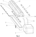
- a simulated solid fuel includes a fuel body, a flow guiding device, a mist source and a light source.
- the fuel body is a hollow structure and is provided with a mist distribution chamber and an air directing chamber.
- the mist distribution chamber and the air directing chamber are isolated from each other inside the fuel body, and mist outlets are disposed on a peripheral surface of the fuel body.
- the mist outlets can be disposed on one side, two sides, three sides, four sides or all the surface of the fuel body, and the mist outlets communicate with the mist distribution chamber.
- the fuel body is further provided with mist inlets, and the mist inlets communicate with the mist distribution chamber.
- the mist source is a device capable of generating mist, such as a device generating mist by an ultrasonic atomizing device, and is disposed at a suitable position.
- the mist source is provided with a mist delivery pipe, and the mist source is connected to the mist inlets through the mist delivery pipe.
- An air ejection port is provided in the top surface of the fuel body, and the air ejection port communicates with the air directing chamber.
- the flow guiding device can guide the air in the air directing chamber to rise upwardly and then be ejected from the air ejection port.
- the mist generated by the mist source enters the mist distribution chamber through the mist delivery pipe, and then emerges from the mist outlets. Since air is ejected from the air ejection port, the air velocity in the middle region of the upper surface of the fuel body is higher and the air pressure is lowered, which will cause the mist emerging from the mist outlets to have a tendency to move toward the middle region of the upper surface of the fuel body, i.e., to move along and rise upward from the upper surface of the fuel body.
- the light source may be disposed on a surface and/or both sides and/or inside of the fuel body, and light emitted from the light source is irradiated on the mist emerging from the mist outlets.
- the puffs of mist create various upward moving shapes to simulate the state of flame combustion.
- the pressure of the mist entering the mist distribution chamber through the mist delivery pipe is higher than the atmospheric pressure to give the mist the power to move forward by using, for example, an air blowing device disposed in the mist generator to blow the mist into the mist distribution chamber.
- the flow guiding device is a heat source disposed inside or at the bottom of the air directing chamber, and the heat source heats the air in the air directing chamber, causing the air in the air directing chamber to move upward.
- the flow guiding device is an air blowing device disposed inside or at the bottom of the air directing chamber, and the air in the air directing chamber is blown upward by the air blowing device.
- the light source has a bar shape and is disposed on both sides of the fuel body, and the light emitted from the light source aims, at an angle, at the space above the mist outlets and the fuel body.
- the present invention has these advantages: a variety of flickering flame-like shapes are formed on both sides and the upper surface of the simulated solid fuel by using the mist, and the light is irradiated on the mist to form a shape that simulates the combustion of a real flame, and the simulated solid fuel has a simple structure and convenient production process and is suitable for use as a simulation device in most electric fireplaces.
- the reference numbers of the components in the figures are: 1 - fuel body; 2 - flow guiding device; 3 - mist source; 4 - light source; 11 - mist distribution chamber; 12 - air directing chamber; 13 - mist outlet; 14 - mist inlet; 15 - air ejection port; 21 - fan; 31 - mist delivery pipe.
- a simulated solid fuel includes a fuel body 1, a flow guiding device 2, a mist source 3 and a light source 4.
- the fuel body 1 has a hollow structure and is provided with a mist distribution chamber 11 and an air directing chamber 12.
- the mist distribution chamber 11 and the air directing chamber 12 do not communicate with each other inside the fuel body 1, and mist outlets 13 are disposed on the periphery of the edge of the fuel body 1.
- the mist outlets 13 are disposed on both sides of the fuel body 1.
- the fuel body 1 is provided with mist inlets 14, and the mist inlets 14 communicate with the mist distribution chamber 11 and are connected to a mist delivery pipe 31 on the mist source 3.
- the mist source 3 is an atomizing ultrasonic mist generator.
- the fuel body 1 is further provided with an air ejection port 15, and the air ejection port 15 communicates with the air directing chamber 12.
- the flow guiding device 2 is a heat source in the form of an electric heating tube, which is disposed inside the air directing chamber 12. Due to the heating of the electric heating tube, the air in the air directing chamber 12 is heated to form a rising air flow.
- the light source 4 is two LED light panels disposed on both sides of the fuel body 1, and the light emitted from the light source 4 is irradiated obliquely and upward toward the fuel body 1.
- mist is generated inside the mist source 3, and the mist is delivered into the mist distribution chamber 11 through the mist delivery pipe 31 by a power device inside the mist source 3.
- the mist will vent from the mist outlets 13.
- the flow guiding device 2 is started simultaneously or subsequently or in advance, and the flow guiding device 2, that is, the electric heating tube starts to heat the air in the air directing chamber 12. Since the air expands after being heated, it is ejected from the air ejection port 15, thereby forming an air flow in the middle area of the upper surface of the fuel body 1.
- This will cause the mist venting from the mist outlets 13 to have a tendency to move toward the middle area of the upper surface of the fuel body 1, i.e., moving along and rise upwardly from the upper surface of the fuel body 1.
- the light emitted from the light source 4 is irradiated on the mist venting from the mist outlets 13, and the puffs of mist create various upward flame-like shapes to simulate the state of real solid fuel flame combustion.
- a simulated solid fuel includes a fuel body 1, a flow guiding device 2, a mist source 3 and a light source 4.
- the fuel body 1 has a hollow structure and is provided with a mist distribution chamber 11 and an air directing chamber 12.
- the mist distribution chamber 11 and the air directing chamber 12 do not communicate with each other inside the fuel body 1, and mist outlets 13 are disposed on the periphery of the edge of the fuel body 1.
- the mist outlets 13 are disposed on four side edges and the upper surface region of the fuel body 1.
- the fuel body 1 is provided with mist inlets 14, and the mist inlets 14 communicate with the mist distribution chamber 11 and are connected to a mist delivery pipe 31 on the mist source 3.
- the mist source 3 is an atomizing ultrasonic mist generator.
- the fuel body 1 is further provided with an air ejection port 15, and the air ejection port 15 communicates with the air directing chamber 12.
- the flow guiding device 2 is an air duct powered by a fan 21, which is disposed at the bottom of the air directing chamber 12, and the flow guiding device 2 provides an upwardly rising air flow in the air directing chamber 12.
- the light source 4 is three LED light panels respectively disposed on the two sides of the fuel body 1 and inside the fuel body 1, and the light emitted from the light source 4 is irradiated obliquely upward and/or upward toward the upper surface of the fuel body 1.
- mist is generated inside the mist source 3, and the mist is delivered into the mist distribution chamber 11 through the mist delivery pipe 31 by a power device inside the mist source 3.
- the mist will vent from the mist outlets 13.
- the flow guiding device 2 is started simultaneously or subsequently or in advance, and under the action of the fan 21, the air in the air directing chamber 12 moves upward and is then ejected from the air ejection port 15, thereby forming an air flow in the middle area of the upper surface of the fuel body 1. According to aerodynamics, the faster the gas velocity, the lower the pressure, so the pressure in the middle area of the upper surface of the fuel body 1 is lowered.
- mist venting from the mist outlets 13 will cause the mist venting from the mist outlets 13 to have a tendency to move toward the middle area of the upper surface of the fuel body 1, i.e., move along and rise upwardly from the upper surface of the fuel body 1.
- the light emitted from the light source 4 is irradiated on the mist emerging from the mist outlets 13.
- the puffs of mist create various upward flame-like shapes are formed to simulate the state of real solid fuel flame combustion.
Landscapes
- Engineering & Computer Science (AREA)
- Chemical & Material Sciences (AREA)
- Combustion & Propulsion (AREA)
- Mechanical Engineering (AREA)
- General Engineering & Computer Science (AREA)
- Physics & Mathematics (AREA)
- General Physics & Mathematics (AREA)
- Theoretical Computer Science (AREA)
- Fire-Extinguishing By Fire Departments, And Fire-Extinguishing Equipment And Control Thereof (AREA)
Claims (7)
- Simulierter fester Brennstoff, der umfasst: einen Brennstoffkörper (1), eine Strömungsführungsvorrichtung (2), eine Nebelquelle (3) und eine Lichtquelle (4), wobei der Brennstoffkörper (1) innen eine hohle Struktur aufweist und innen mit einer Nebelverteilungskammer (11) und einer Luftleitkammer (12) versehen ist, wobei die Nebelverteilungskammer (11) und die Luftleitkammer (12) innerhalb des Brennstoffkörpers (1) voneinander isoliert sind, Nebelauslässe (13) und Nebeleinlässe (14) jeweils an einer äußeren Oberfläche des Brennstoffkörpers (1) angeordnet sind, die Nebelauslässe (13) und die Nebeleinlässe (14) alle mit der Nebelverteilungskammer (11) in Verbindung stehen,eine obere Oberfläche des Brennstoffkörpers (1) mit einer Luftausstoßöffnung (15) versehen ist, wobei die Luftausstoßöffnung (15) mit der Luftleitkammer (12) in Verbindung steht; wobeidie Nebelquelle (3) eine Vorrichtung ist, die zum Erzeugen von Nebel in der Lage ist, wobei die Nebelquelle (3) mit einem Nebelzufuhrrohr (31) versehen ist, das mit den Nebeleinlässen (14) verbunden ist, und die Nebelquelle (3) den Nebel zur Nebelverteilungskammer (11) durch das Nebelzufuhrrohr (31) zuführt;die Strömungsführungsvorrichtung (2) innerhalb der oder an der Unterseite der Luftleitkammer (12) angeordnet ist, so dass Luft innerhalb der Luftleitkammer (12) eine aufwärts ansteigende Luftströmung bildet; undLicht, das von der Lichtquelle (4) emittiert wird, auf den Nebel abgestrahlt wird, der aus den Nebelauslässen (13) abgelassen wird, dadurch gekennzeichnet, dass:
die Nebelauslässe (13) an einer Umfangsoberfläche des Brennstoffkörpers (1) angeordnet sind. - Simulierter fester Brennstoff nach Anspruch 1, wobei der Druck des Nebels, der durch das Nebelzufuhrrohr (31) zur Nebelverteilungskammer (11) zugeführt wird, höher ist als der Atmosphärendruck.
- Simulierter fester Brennstoff nach Anspruch 1, wobei die Strömungsführungsvorrichtung (2) eine Wärmequelle ist, die innerhalb der oder an der Unterseite der Luftleitkammer (12) angeordnet ist.
- Simulierter fester Brennstoff nach Anspruch 1, wobei die Strömungsführungsvorrichtung (2) eine Luftblasvorrichtung ist, die innerhalb der oder an der Unterseite der Luftleitkammer (12) angeordnet ist.
- Simulierter fester Brennstoff nach Anspruch 1, wobei die Lichtquelle (4) eine Stabform aufweist und auf beiden Seiten des Brennstoffkörpers (1) angeordnet ist, und das Licht, das von der Lichtquelle (4) emittiert wird, in einem Winkel auf einen Raum über sowohl den Nebelauslässen (13) als auch der oberen Oberfläche des Brennstoffkörpers (1) zielt.
- Simulierter fester Brennstoff nach Anspruch 1, wobei die Nebelquelle (3) durch einen Ultraschallzerstäubungsnebelgenerator erzeugt wird.
- Simulierter fester Brennstoff nach Anspruch 1, wobei die Nebeleinlässe (14) an einer Endoberfläche oder einer unteren Oberfläche des Brennstoffkörpers (1) angeordnet sind.
Applications Claiming Priority (2)
| Application Number | Priority Date | Filing Date | Title |
|---|---|---|---|
| CN201920585592.6U CN209445274U (zh) | 2019-04-26 | 2019-04-26 | 一种仿真固体燃料 |
| CN201910344144.1A CN110307513B (zh) | 2019-04-26 | 2019-04-26 | 一种仿真固体燃料 |
Publications (3)
| Publication Number | Publication Date |
|---|---|
| EP3730840A1 EP3730840A1 (de) | 2020-10-28 |
| EP3730840B1 true EP3730840B1 (de) | 2023-08-02 |
| EP3730840C0 EP3730840C0 (de) | 2023-08-02 |
Family
ID=67742275
Family Applications (1)
| Application Number | Title | Priority Date | Filing Date |
|---|---|---|---|
| EP19193377.9A Active EP3730840B1 (de) | 2019-04-26 | 2019-08-23 | Simulierter festbrennstoff |
Country Status (4)
| Country | Link |
|---|---|
| US (1) | US10762805B1 (de) |
| EP (1) | EP3730840B1 (de) |
| ES (1) | ES2956777T3 (de) |
| PL (1) | PL3730840T3 (de) |
Families Citing this family (1)
| Publication number | Priority date | Publication date | Assignee | Title |
|---|---|---|---|---|
| CA3198612C (en) * | 2023-05-04 | 2024-07-02 | Hybrid Energies Alternative Technologies Inc. | Electric fireplace with synthetic material for thermal radiation |
Family Cites Families (11)
| Publication number | Priority date | Publication date | Assignee | Title |
|---|---|---|---|---|
| US7762897B2 (en) * | 2002-04-04 | 2010-07-27 | Technifex, Inc. | Apparatus for producing a fire special effect |
| GB2391933A (en) * | 2002-06-20 | 2004-02-18 | Lfl Group Ltd | Visual fire effect with an ultrasonic mist generator |
| US20100031543A1 (en) * | 2008-08-05 | 2010-02-11 | James Rice | Systems for faux wood burning heating apparatuses, faux wood burning heating apparatuses and inserts for faux wood burning heating apparatuses producing realistic looking faux fire effects, and methods of emulating a wood burning heating apparatus |
| GB2502077B (en) * | 2012-05-15 | 2016-04-06 | Basic Holdings | A simulated flame effect fire |
| CN203364326U (zh) * | 2013-05-31 | 2013-12-25 | 赵信军 | 多功能仿真3d火焰加湿加热装置 |
| WO2014201586A1 (zh) * | 2013-06-20 | 2014-12-24 | 泉州顺通艺品有限公司 | 带加湿功能电壁炉 |
| US20160195277A1 (en) * | 2015-01-07 | 2016-07-07 | Zhongshan City Shende Electrical Appliance Ltd. | Simulation electric fireplace having mist, humidifying and heating functions |
| CN107305030A (zh) * | 2016-04-22 | 2017-10-31 | 李晓锋 | 电子壁炉装置及模拟原木木柴壁炉的方法 |
| NL2016970B1 (en) * | 2016-06-15 | 2017-12-21 | Ruby Decor B V | Hearth-fire simulating apparatus. |
| US9709282B1 (en) * | 2016-08-08 | 2017-07-18 | Afc (Alex Fireplace Company) Limited | Device for simulating a flame effect |
| CN108613093B (zh) * | 2018-05-16 | 2023-04-18 | 佛山市彤辉电子壁炉有限公司 | 一种仿真火焰装置和方法 |
-
2019
- 2019-08-23 PL PL19193377.9T patent/PL3730840T3/pl unknown
- 2019-08-23 ES ES19193377T patent/ES2956777T3/es active Active
- 2019-08-23 EP EP19193377.9A patent/EP3730840B1/de active Active
- 2019-09-27 US US16/585,189 patent/US10762805B1/en active Active
Also Published As
| Publication number | Publication date |
|---|---|
| ES2956777T3 (es) | 2023-12-27 |
| EP3730840C0 (de) | 2023-08-02 |
| EP3730840A1 (de) | 2020-10-28 |
| US10762805B1 (en) | 2020-09-01 |
| PL3730840T3 (pl) | 2024-01-15 |
Similar Documents
| Publication | Publication Date | Title |
|---|---|---|
| EP3745029B1 (de) | Flammensimulationsvorrichtung und simulierter kamin mit einer solchen vorrichtung | |
| JP5281417B2 (ja) | 電気的火炎 | |
| CN101883953B (zh) | 电炉 | |
| WO2020064028A2 (zh) | 一种仿真立体火焰装置 | |
| CN111043641B (zh) | 一种火焰仿真装置以及包含有其的雾化仿真壁炉 | |
| US20100031543A1 (en) | Systems for faux wood burning heating apparatuses, faux wood burning heating apparatuses and inserts for faux wood burning heating apparatuses producing realistic looking faux fire effects, and methods of emulating a wood burning heating apparatus | |
| EP3730840B1 (de) | Simulierter festbrennstoff | |
| CN210688082U (zh) | 一种改进型仿真立体火焰装置 | |
| CN217080829U (zh) | 模拟龙卷风生成器及加湿器 | |
| CN205796550U (zh) | 仿火舞台烟喷射机喷射面板、机箱及仿火舞台烟喷射机 | |
| CN209445274U (zh) | 一种仿真固体燃料 | |
| CN210373693U (zh) | 一种火焰仿真装置以及包含有其的雾化仿真壁炉 | |
| CN112419863B (zh) | 一种飞机客舱训练用模拟火焰燃烧与熄灭的装置 | |
| CN220169541U (zh) | 蒸汽雾化3d火焰仿真电壁炉 | |
| CN110307513B (zh) | 一种仿真固体燃料 | |
| CN214279395U (zh) | 一种飞机客舱训练用模拟火焰燃烧与熄灭的装置 | |
| CN204073364U (zh) | 烟雾器、用于提示实体游戏角色的状态信息的提示装置、以及遥控战车 | |
| US11898710B2 (en) | Flame simulating device and atomizing simulation fireplace including same | |
| WO2024107072A1 (en) | Flame stimulating device | |
| CN216048384U (zh) | 一种装配式雾化壁炉的嵌合造型安装设计结构 | |
| CN217273888U (zh) | 一种火焰仿真装置以及包含有其的雾化仿真壁炉 | |
| CN206637702U (zh) | 一种仿真火焰电壁炉 | |
| CN209181048U (zh) | 一种仿真电壁炉 | |
| CN203744257U (zh) | 一种适用于加氢重整装置的燃烧器 | |
| CN116772274A (zh) | 蒸汽雾化3d火焰仿真电壁炉 |
Legal Events
| Date | Code | Title | Description |
|---|---|---|---|
| PUAI | Public reference made under article 153(3) epc to a published international application that has entered the european phase |
Free format text: ORIGINAL CODE: 0009012 |
|
| STAA | Information on the status of an ep patent application or granted ep patent |
Free format text: STATUS: THE APPLICATION HAS BEEN PUBLISHED |
|
| AK | Designated contracting states |
Kind code of ref document: A1 Designated state(s): AL AT BE BG CH CY CZ DE DK EE ES FI FR GB GR HR HU IE IS IT LI LT LU LV MC MK MT NL NO PL PT RO RS SE SI SK SM TR |
|
| AX | Request for extension of the european patent |
Extension state: BA ME |
|
| STAA | Information on the status of an ep patent application or granted ep patent |
Free format text: STATUS: REQUEST FOR EXAMINATION WAS MADE |
|
| 17P | Request for examination filed |
Effective date: 20210422 |
|
| RBV | Designated contracting states (corrected) |
Designated state(s): AL AT BE BG CH CY CZ DE DK EE ES FI FR GB GR HR HU IE IS IT LI LT LU LV MC MK MT NL NO PL PT RO RS SE SI SK SM TR |
|
| RIC1 | Information provided on ipc code assigned before grant |
Ipc: F24C 7/00 20060101ALI20230126BHEP Ipc: F24B 1/18 20060101AFI20230126BHEP |
|
| GRAP | Despatch of communication of intention to grant a patent |
Free format text: ORIGINAL CODE: EPIDOSNIGR1 |
|
| STAA | Information on the status of an ep patent application or granted ep patent |
Free format text: STATUS: GRANT OF PATENT IS INTENDED |
|
| INTG | Intention to grant announced |
Effective date: 20230321 |
|
| GRAS | Grant fee paid |
Free format text: ORIGINAL CODE: EPIDOSNIGR3 |
|
| GRAA | (expected) grant |
Free format text: ORIGINAL CODE: 0009210 |
|
| STAA | Information on the status of an ep patent application or granted ep patent |
Free format text: STATUS: THE PATENT HAS BEEN GRANTED |
|
| AK | Designated contracting states |
Kind code of ref document: B1 Designated state(s): AL AT BE BG CH CY CZ DE DK EE ES FI FR GB GR HR HU IE IS IT LI LT LU LV MC MK MT NL NO PL PT RO RS SE SI SK SM TR |
|
| REG | Reference to a national code |
Ref country code: GB Ref legal event code: FG4D |
|
| REG | Reference to a national code |
Ref country code: CH Ref legal event code: EP |
|
| REG | Reference to a national code |
Ref country code: DE Ref legal event code: R096 Ref document number: 602019033908 Country of ref document: DE |
|
| REG | Reference to a national code |
Ref country code: IE Ref legal event code: FG4D |
|
| U01 | Request for unitary effect filed |
Effective date: 20230901 |
|
| U07 | Unitary effect registered |
Designated state(s): AT BE BG DE DK EE FI FR IT LT LU LV MT NL PT SE SI Effective date: 20230922 |
|
| REG | Reference to a national code |
Ref country code: ES Ref legal event code: FG2A Ref document number: 2956777 Country of ref document: ES Kind code of ref document: T3 Effective date: 20231227 |
|
| U20 | Renewal fee for the european patent with unitary effect paid |
Year of fee payment: 5 Effective date: 20231123 |
|
| PG25 | Lapsed in a contracting state [announced via postgrant information from national office to epo] |
Ref country code: GR Free format text: LAPSE BECAUSE OF FAILURE TO SUBMIT A TRANSLATION OF THE DESCRIPTION OR TO PAY THE FEE WITHIN THE PRESCRIBED TIME-LIMIT Effective date: 20231103 |
|
| PG25 | Lapsed in a contracting state [announced via postgrant information from national office to epo] |
Ref country code: IS Free format text: LAPSE BECAUSE OF FAILURE TO SUBMIT A TRANSLATION OF THE DESCRIPTION OR TO PAY THE FEE WITHIN THE PRESCRIBED TIME-LIMIT Effective date: 20231202 |
|
| PG25 | Lapsed in a contracting state [announced via postgrant information from national office to epo] |
Ref country code: RS Free format text: LAPSE BECAUSE OF FAILURE TO SUBMIT A TRANSLATION OF THE DESCRIPTION OR TO PAY THE FEE WITHIN THE PRESCRIBED TIME-LIMIT Effective date: 20230802 Ref country code: NO Free format text: LAPSE BECAUSE OF FAILURE TO SUBMIT A TRANSLATION OF THE DESCRIPTION OR TO PAY THE FEE WITHIN THE PRESCRIBED TIME-LIMIT Effective date: 20231102 Ref country code: IS Free format text: LAPSE BECAUSE OF FAILURE TO SUBMIT A TRANSLATION OF THE DESCRIPTION OR TO PAY THE FEE WITHIN THE PRESCRIBED TIME-LIMIT Effective date: 20231202 Ref country code: HR Free format text: LAPSE BECAUSE OF FAILURE TO SUBMIT A TRANSLATION OF THE DESCRIPTION OR TO PAY THE FEE WITHIN THE PRESCRIBED TIME-LIMIT Effective date: 20230802 Ref country code: GR Free format text: LAPSE BECAUSE OF FAILURE TO SUBMIT A TRANSLATION OF THE DESCRIPTION OR TO PAY THE FEE WITHIN THE PRESCRIBED TIME-LIMIT Effective date: 20231103 |
|
| REG | Reference to a national code |
Ref country code: CH Ref legal event code: PL |
|
| PG25 | Lapsed in a contracting state [announced via postgrant information from national office to epo] |
Ref country code: SM Free format text: LAPSE BECAUSE OF FAILURE TO SUBMIT A TRANSLATION OF THE DESCRIPTION OR TO PAY THE FEE WITHIN THE PRESCRIBED TIME-LIMIT Effective date: 20230802 Ref country code: RO Free format text: LAPSE BECAUSE OF FAILURE TO SUBMIT A TRANSLATION OF THE DESCRIPTION OR TO PAY THE FEE WITHIN THE PRESCRIBED TIME-LIMIT Effective date: 20230802 Ref country code: CZ Free format text: LAPSE BECAUSE OF FAILURE TO SUBMIT A TRANSLATION OF THE DESCRIPTION OR TO PAY THE FEE WITHIN THE PRESCRIBED TIME-LIMIT Effective date: 20230802 Ref country code: CH Free format text: LAPSE BECAUSE OF NON-PAYMENT OF DUE FEES Effective date: 20230831 Ref country code: SK Free format text: LAPSE BECAUSE OF FAILURE TO SUBMIT A TRANSLATION OF THE DESCRIPTION OR TO PAY THE FEE WITHIN THE PRESCRIBED TIME-LIMIT Effective date: 20230802 |
|
| REG | Reference to a national code |
Ref country code: DE Ref legal event code: R097 Ref document number: 602019033908 Country of ref document: DE |
|
| REG | Reference to a national code |
Ref country code: IE Ref legal event code: MM4A |
|
| PG25 | Lapsed in a contracting state [announced via postgrant information from national office to epo] |
Ref country code: MC Free format text: LAPSE BECAUSE OF FAILURE TO SUBMIT A TRANSLATION OF THE DESCRIPTION OR TO PAY THE FEE WITHIN THE PRESCRIBED TIME-LIMIT Effective date: 20230802 |
|
| PLBE | No opposition filed within time limit |
Free format text: ORIGINAL CODE: 0009261 |
|
| STAA | Information on the status of an ep patent application or granted ep patent |
Free format text: STATUS: NO OPPOSITION FILED WITHIN TIME LIMIT |
|
| PG25 | Lapsed in a contracting state [announced via postgrant information from national office to epo] |
Ref country code: IE Free format text: LAPSE BECAUSE OF NON-PAYMENT OF DUE FEES Effective date: 20230823 |
|
| 26N | No opposition filed |
Effective date: 20240503 |
|
| PG25 | Lapsed in a contracting state [announced via postgrant information from national office to epo] |
Ref country code: IE Free format text: LAPSE BECAUSE OF NON-PAYMENT OF DUE FEES Effective date: 20230823 |
|
| U20 | Renewal fee for the european patent with unitary effect paid |
Year of fee payment: 6 Effective date: 20240827 |
|
| PG25 | Lapsed in a contracting state [announced via postgrant information from national office to epo] |
Ref country code: CY Free format text: LAPSE BECAUSE OF FAILURE TO SUBMIT A TRANSLATION OF THE DESCRIPTION OR TO PAY THE FEE WITHIN THE PRESCRIBED TIME-LIMIT; INVALID AB INITIO Effective date: 20190823 |
|
| PG25 | Lapsed in a contracting state [announced via postgrant information from national office to epo] |
Ref country code: HU Free format text: LAPSE BECAUSE OF FAILURE TO SUBMIT A TRANSLATION OF THE DESCRIPTION OR TO PAY THE FEE WITHIN THE PRESCRIBED TIME-LIMIT; INVALID AB INITIO Effective date: 20190823 |
|
| U20 | Renewal fee for the european patent with unitary effect paid |
Year of fee payment: 7 Effective date: 20250827 |
|
| PGFP | Annual fee paid to national office [announced via postgrant information from national office to epo] |
Ref country code: ES Payment date: 20250926 Year of fee payment: 7 |
|
| PGFP | Annual fee paid to national office [announced via postgrant information from national office to epo] |
Ref country code: PL Payment date: 20250822 Year of fee payment: 7 |
|
| PGFP | Annual fee paid to national office [announced via postgrant information from national office to epo] |
Ref country code: GB Payment date: 20250829 Year of fee payment: 7 |
|
| PG25 | Lapsed in a contracting state [announced via postgrant information from national office to epo] |
Ref country code: TR Free format text: LAPSE BECAUSE OF FAILURE TO SUBMIT A TRANSLATION OF THE DESCRIPTION OR TO PAY THE FEE WITHIN THE PRESCRIBED TIME-LIMIT Effective date: 20230802 |