EP3730812A1 - Weight roller, method of manufacturing same, and mold for use in manufacturing weight roller - Google Patents
Weight roller, method of manufacturing same, and mold for use in manufacturing weight roller Download PDFInfo
- Publication number
- EP3730812A1 EP3730812A1 EP19752011.7A EP19752011A EP3730812A1 EP 3730812 A1 EP3730812 A1 EP 3730812A1 EP 19752011 A EP19752011 A EP 19752011A EP 3730812 A1 EP3730812 A1 EP 3730812A1
- Authority
- EP
- European Patent Office
- Prior art keywords
- covering member
- weight
- weight roller
- adjusting member
- mold
- Prior art date
- Legal status (The legal status is an assumption and is not a legal conclusion. Google has not performed a legal analysis and makes no representation as to the accuracy of the status listed.)
- Granted
Links
Images





Classifications
-
- F—MECHANICAL ENGINEERING; LIGHTING; HEATING; WEAPONS; BLASTING
- F16—ENGINEERING ELEMENTS AND UNITS; GENERAL MEASURES FOR PRODUCING AND MAINTAINING EFFECTIVE FUNCTIONING OF MACHINES OR INSTALLATIONS; THERMAL INSULATION IN GENERAL
- F16H—GEARING
- F16H55/00—Elements with teeth or friction surfaces for conveying motion; Worms, pulleys or sheaves for gearing mechanisms
- F16H55/32—Friction members
- F16H55/52—Pulleys or friction discs of adjustable construction
- F16H55/56—Pulleys or friction discs of adjustable construction of which the bearing parts are relatively axially adjustable
- F16H55/563—Pulleys or friction discs of adjustable construction of which the bearing parts are relatively axially adjustable actuated by centrifugal masses
-
- B—PERFORMING OPERATIONS; TRANSPORTING
- B29—WORKING OF PLASTICS; WORKING OF SUBSTANCES IN A PLASTIC STATE IN GENERAL
- B29C—SHAPING OR JOINING OF PLASTICS; SHAPING OF MATERIAL IN A PLASTIC STATE, NOT OTHERWISE PROVIDED FOR; AFTER-TREATMENT OF THE SHAPED PRODUCTS, e.g. REPAIRING
- B29C33/00—Moulds or cores; Details thereof or accessories therefor
- B29C33/12—Moulds or cores; Details thereof or accessories therefor with incorporated means for positioning inserts, e.g. labels
-
- B—PERFORMING OPERATIONS; TRANSPORTING
- B29—WORKING OF PLASTICS; WORKING OF SUBSTANCES IN A PLASTIC STATE IN GENERAL
- B29C—SHAPING OR JOINING OF PLASTICS; SHAPING OF MATERIAL IN A PLASTIC STATE, NOT OTHERWISE PROVIDED FOR; AFTER-TREATMENT OF THE SHAPED PRODUCTS, e.g. REPAIRING
- B29C45/00—Injection moulding, i.e. forcing the required volume of moulding material through a nozzle into a closed mould; Apparatus therefor
- B29C45/17—Component parts, details or accessories; Auxiliary operations
- B29C45/26—Moulds
-
- F—MECHANICAL ENGINEERING; LIGHTING; HEATING; WEAPONS; BLASTING
- F16—ENGINEERING ELEMENTS AND UNITS; GENERAL MEASURES FOR PRODUCING AND MAINTAINING EFFECTIVE FUNCTIONING OF MACHINES OR INSTALLATIONS; THERMAL INSULATION IN GENERAL
- F16H—GEARING
- F16H9/00—Gearings for conveying rotary motion with variable gear ratio, or for reversing rotary motion, by endless flexible members
- F16H9/02—Gearings for conveying rotary motion with variable gear ratio, or for reversing rotary motion, by endless flexible members without members having orbital motion
- F16H9/04—Gearings for conveying rotary motion with variable gear ratio, or for reversing rotary motion, by endless flexible members without members having orbital motion using belts, V-belts, or ropes
- F16H9/12—Gearings for conveying rotary motion with variable gear ratio, or for reversing rotary motion, by endless flexible members without members having orbital motion using belts, V-belts, or ropes engaging a pulley built-up out of relatively axially-adjustable parts in which the belt engages the opposite flanges of the pulley directly without interposed belt-supporting members
Definitions
- the present disclosure relates to a weight roller, a method of manufacturing a weight roller, and a mold for use in manufacturing a weight roller.
- Some types of motorcycles include a stepless transmission that automatically changes speed in accordance with the number of revolutions of the engine.
- the stepless transmission includes a pulley including a fixed plate and a movable plate, a V-belt wound around the pulley, a guide plate disposed at the back of the movable plate and fastened to a rotary shaft, and cylindrical weight rollers disposed in a gap between the guide plate and the movable plate and configured to move in the radial direction of the pulley.
- weight rollers include a cylindrical weight adjusting member and a covering member covering, for example, the outer peripheral surface of the weight adjusting member.
- the covering member is made of, for example, a resin composition.
- Patent Document 1 discloses such a weight roller and a method of manufacturing the weight roller with a mold.
- Patent Document 1 Japanese Unexamined Patent Publication No. S61-163821
- Weight rollers are manufactured such that, for example, a weight adjusting member is placed in a mold and a resin composition is injected into a cavity formed around the weight adjusting member to form a covering member.
- resin composition burrs may be formed on the covering member. If a burr is formed, the burr becomes a protruding portion raised in the up-down direction (in a direction orthogonal to the bottom surface and the upper surface of the cylindrical shape) or in the circumferential direction. The protruding portion increases the dimension in these directions, and this increase may deteriorate the performance of the weight rollers. It is possible to remove the burr formed on the covering member, but this requires additional processes, thereby increasing the manufacturing processes and manufacturing costs.
- the following describes a technique of implementing a weight roller that can reduce performance deterioration due to formation of burrs, a method of manufacturing the same, and a mold for use in manufacturing the weight roller.
- a weight roller according to the present disclosure includes a weight adjusting member having a cylindrical shape and a covering member covering at least an outer peripheral surface and part of a bottom surface of the weight adjusting member, the covering member protruding beyond an upper surface and the bottom surface of the weight adjusting member.
- the covering member is made of a resin composition.
- the covering member is formed by a mold having a split portion disposed at a position not corresponding to the endmost surface of an upper surface or a bottom surface of the covering member.
- a mold according to the present disclosure includes a set of molds for use in manufacturing a weight roller including a weight adjusting member having a cylindrical shape and a covering member made of a resin composition, by injecting the resin composition onto the weight adjusting member.
- the set of molds has at least one split portion and defines a cavity formed with the set of molds are closed with the weight adjusting member being accommodated in the cavity to form the covering member covering at least an outer peripheral surface and part of a bottom surface of the weight adjusting member, the covering member protruding beyond an upper surface and the bottom surface of the weight adjusting member.
- the split portion is disposed at a position not corresponding to an endmost surface of an upper surface or a bottom surface of the covering member.
- a method of manufacturing a weight roller according to the present disclosure includes placing a weight adjusting member having a cylindrical shape in a cavity defined by a set of molds having at least one split portion, and forming a covering member by injecting a resin composition from a gate into the cavity, the covering member covering at least an outer peripheral surface and part of a bottom surface of the weight adjusting member and protruding beyond an upper surface and the bottom surface of the weight adjusting member.
- the split portion is disposed at a position not corresponding to an endmost surface of an upper surface or a bottom surface of the covering member.
- the technique according to the present disclosure can prevent formation of burrs on the endmost surface of the upper surface and the bottom surface of the covering member of the weight roller and can prevent an increase in dimension due to the formation of burrs and can prevent resulting deterioration of performance.
- FIG. 1 is a diagram illustrating an example weight roller 1 according to a first embodiment.
- FIG. 1 illustrates, at the left side, a sectional view taken in parallel with the axis of the weight roller 1 and illustrates, at the right side, a plan view of the weight roller 1 seen from its bottom surface.
- an end surface of the cylindrical weight roller 1 having a gate mark may be referred to as a bottom or a lower side, and the opposite surface may be referred to as an upper side.
- the weight roller 1 includes a cylindrical weight adjusting member 3 and a covering member 5 made of a resin composition and disposed on an outer peripheral surface 7 of the weight adjusting member 3.
- the weight roller 1 generally has a cylindrical shape.
- the covering member 5 may cover not only the outer peripheral surface 7 of the weight adjusting member 3, but also the bottom surface and at least part of the upper surface of the weight adjusting member 3 so that, for example, the weight adjusting member 3 will not fall off the covering member 5.
- the covering member 5 has a blind cylindrical shape and may have a circular disk gate mark 11 at the center of the bottom when seen in the plan view.
- the covering member 5 is formed by insert molding using a disk gate.
- the covering member 5 is in contact with the region of the weight adjusting member 3 extending from part of the upper surface to the outer peripheral surface 7 and part of the lower surface.
- the thickness of the covering member 5 covering the outer peripheral surface of the weight adjusting member 3 is substantially uniform except at the upper and lower ends.
- the thickness may be, for example, about 1.5 mm or more and 2.5 mm or less. If the thickness of the covering member 5 is too small, the covering member 5 may be broken or cracked due to thermal shock. If the thickness is too large, the manufacturing costs may increase.
- the covering member 5 has portions protruding beyond the upper surface and the lower surface of the weight adjusting member 3. The portions protrude to the upper side and to the lower side (corresponding to the left side and the right side, respectively, in the diagram at the left side in FIG. 1 ) relative to the weight adjusting member 3. At the lower side, the covering member 5 covers the lower surface of the weight adjusting member 3, and this lower portion protrudes to the lower side relative to the weight adjusting member 3. At the upper side, the covering member 5 covers part of the periphery of the upper surface of the weight adjusting member 3, and this upper portion protrudes to the upper side relative to the weight adjusting member 3.
- FIG. 2 is an enlarged view of a peripheral portion close to the upper surface of the weight roller 1.
- the covering member 5 has an outer chamfered portion 5a having a chamfered shape along the outer periphery of the upper surface.
- the covering member 5 has an outer chamfered portion 5b having a chamfered shape along the outer periphery of the lower surface.
- the reference characters 16a, 16b, and 16d will be described later.
- the weight roller 1 may have an outer diameter of about 15 mm to 30 mm and have a height of about 12 mm to 20 mm, for example. Specifically, the weight roller 1 has, for example, an outer diameter of 20 mm and a height of 15 mm.
- the covering member 5 is made of a self-lubricating resin composition.
- a "self-lubricating" material is a material having a small coefficient of friction. Using a self-lubricating resin composition can reduce the amount to be worn when the weight roller 1 slides relative to a metal member.
- the covering member 5 is made of, for example, polyamide as a base resin, and includes fibers and lubricant.
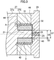
- FIG. 3 is a sectional view illustrating an example method of manufacturing the weight roller 1 illustrated in FIG. 1 .
- the weight roller 1 according to the first embodiment is manufactured by insert molding.
- a cylindrical weight adjusting member 3 made of metal is formed in a separate process by a known molding method using a mold, for example.
- the weight adjusting member 3 has a hole concentric with the external shape.
- polyamide resin (resin 31) doped with a predetermined content of predetermined additives (e.g., inorganic fibers, organic fibers, and lubricant) as described above is kneaded such that the fibers and lubricant are uniformly mixed.
- the weight adjusting member 3 is formed into a desired shape by forging in a mold or by machining.
- a reference character 37 indicates the inner diameter of the weight adjusting member 3; a reference character 35 indicates the diameter of the core pin 21; and a reference character 33 indicates a difference (i.e., clearance) between the inner diameter 37 of the weight adjusting member 3 and the diameter 35 of the core pin 21.
- the resin 31 in a molten state is then injected into the cavity 32 through the runner 25 and the disk gate 23. After the molds are cooled and the resin 31 is solidified, the molds are opened and the molded weight roller 1 is taken out.
- the temperature of the first mold 27 and the second mold 29 in injecting the resin 31 is determined depending on the base resin. When, for example, nylon 66 or nylon 46 is used as a base resin, the mold temperature is set to about 80°C to 90°C.
- the surface close to the runner 25 corresponds to the lower surface of the weight roller 1.
- the resin 31 is injected from the disk gate 23 disposed at the center of a cavity end surface, and the weight adjusting member 3 is thus centered by a flow 40 of the resin 31 traveling from the center of the cavity end surface toward the periphery.
- This configuration provides less positional variation of the clearance 33 and thus can reduce misalignment between the center axis of the weight adjusting member 3 and the center axis of the core pin 21.
- the resin 31 When the resin 31 reaches the periphery of the lower surface of the cavity 32, the resin 31 then travels from the lower surface toward the upper surface as indicated by a flow 42 of the resin 31.
- the mold includes a gas vent structure for releasing the gas.
- the first mold 27 has a two-part structure including a first portion 27a and a second portion 27b separated by a first split portion 44 extending in parallel with the upper surface and the lower surface of the weight adjusting member 3.
- the first split portion 44 is disposed at an outer-chamfer forming portion designed to form the outer chamfered portion 5a of the weight roller 1 to be manufactured. Disposing the first split portion 44 at a position close to the flow end of the resin 31 and using the first split portion 44 as a gas vent can release the gas generated during the formation of the covering member 5 with the resin 31.
- the first split portion 44 has a certain gap. Depending on the state of the gap, a burr may be formed. In particular, when weight rollers 1 are manufactured for a long period of time, the molds may deteriorate and the gap of the first split portion 44 may become greater. In this regard, formation of burr may occur more often.
- FIG. 4 illustrates an enlarged diagram of circle A illustrated in FIG. 3 .
- the weight roller 1 has a burr 16a on an outermost peripheral surface 5d of the covering member 5.
- the external dimension of the weight roller 1 in the radial direction increases by the amount of the burr 16a, and this increase affects the performance of the weight roller 1.
- the burr 16a is formed when the split portion is disposed at a position corresponding to the outermost peripheral surface 5d of the covering member 5 as indicated by a dashed line 44a in FIG. 4 .
- the weight roller 1 has a burr 16d on an upper end surface 5g of the covering member 5.
- the height dimension of the weight roller 1 increases by the amount of the burr 16d, and this increase also affects the performance of the weight roller 1.
- the burr 16d is formed when the split portion is disposed at a position corresponding to the upper end surface 5g of the covering member 5 as indicated by a dashed line 44b in FIG. 4 .
- the first split portion 44 is disposed at a position corresponding to the outer chamfered portion 5a (i.e., at an outer-chamfer forming portion 32a), not corresponding to the outermost peripheral surface 5d or the upper end surface 5g.
- the burr such as the burr 16b in FIG. 2
- the burr 16b has no effect on the external dimension of the weight roller 1 in the radial direction.
- the burr 16b has no effect on the height dimension of the weight roller 1. In this regard, the burr 16b, if any, has no effect on the performance of the weight roller 1.
- disposing the first split portion 44 which may form a burr, at a position of the mold not corresponding to the outermost peripheral surface 5d but corresponding to the outer chamfered portion 5a can prevent performance deterioration of the weight roller 1 even if a burr is formed. If a burr is formed by the first split portion 44, there is no need for a process of removing the burr or the accompanying costs.
- a parting line corresponding to the first split portion 44 is typically formed.
- the parting line can indicate that the first split portion 44 is disposed at the position corresponding to the outer chamfered portion 5a.
- the first mold 27 and the second mold 29 are separated by a second split portion 46, and a burr may be formed by the second split portion 46.
- the second split portion 46 is not disposed at a position corresponding to the lower endmost surface. If a burr is formed at this position, the burr has no effect on the height dimension of the weight roller 1. In the first embodiment, variation in the height dimension of the weight roller 1 due to formation of the burr is substantially prevented.
- the burr affects the external dimension of the weight roller 1 in the radial direction.
- the burr formed by the first split portion 44 has no effect on the dimension in the radial direction, the likelihood of burr formation that affects the dimension of the weight roller 1 according to the first embodiment in the radial direction is reduced.
- FIG. 5 is a diagram illustrating an example weight roller 1a according to a second embodiment. Similarly to FIG. 1 , FIG. 5 illustrates, at the left side, a sectional view taken in parallel with the axis of the weight roller 1a and illustrates, at the right side, a plan view seen from the bottom surface of the weight roller 1a.
- FIG. 6 is an enlarged view of a peripheral portion close to the upper surface of the weight roller 1a.
- the weight roller 1a differs from the weight roller 1 according to the first embodiment in that the weight roller 1a has an inner chamfered portion 5c having a chamfered shape along the inner periphery of the upper protruding portion of the covering member 5.
- the inner chamfered portion 5c has a chamfered step C ( FIG. 6 ) of, for example, 0.1 mm or more in the height direction.
- the other configurations of the weight roller 1a are the same as those of the weight roller 1 according to the first embodiment. Reference characters 16c and 16d will be described later.
- the material of the weight roller 1a is the same as the material of the weight roller 1 according to the first embodiment.
- the method of manufacturing the weight roller 1a is the same as the method of manufacturing the weight roller 1 according to the first embodiment.
- a cavity 32 of the mold has a shape for forming the inner chamfered portion 5c, and the separating structure and the disposition of the split portion are different from those of the weight roller 1.
- FIG. 7 is a sectional view illustrating a method of manufacturing the weight roller 1a.
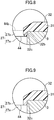
- FIG. 8 illustrates an enlarged diagram of circle B illustrated in FIG. 7 .
- the first mold 27 includes a first portion 27a and a second portion 27b separated by a first split portion 44 provided perpendicular to the upper surface and the lower surface of the weight adjusting member 3.
- the second portion 27b of the first mold 27 has an inner-chamfer forming portion 32b corresponding to the inner chamfered portion 5c.
- a flow end 32c corresponding to the position where the flow 42 of the resin 31 reaches in the end is disposed on a surface facing inward of the weight roller 1a.
- the first split portion 44 when seen in the sectional view taken in parallel with the upper surface of the weight adjusting member 3, has a circular shape that is concentric with the periphery of the weight adjusting member 3, and is disposed at a position corresponding to the flow end 32c.
- the resin 31 is then injected to form the covering member 5 with the first split portion 44 serving as a gas vent.
- a burr may be formed at the position of the first split portion 44.
- a burr 16c, if any, formed at the position of the first split portion 44 has no effect on the dimension (maximum dimension) in the up-down direction of the weight roller 1a unless the burr 16c reaches an extension 5h of the upper end surface 5g (endmost surface) of the covering member 5.
- the formation of the burr 16c therefore, has no effect on the performance of the weight roller 1a.
- the covering member 5 has no inner chamfered portion 5c, that is, the cavity 32 has no inner-chamfer forming portion 32b.
- the structure of the mold in this case is illustrated in FIG. 9 and the resulting weight roller is illustrated in FIG. 10 .
- the resin 31 is injected in the mold illustrated in FIG. 9 and a burr is formed by the first split portion 44.
- a burr 16e is formed as illustrated in FIG. 10 .
- the burr 16e whatever the size may be, protrudes from the upper end surface 5g of the covering member 5 and increases the height dimension of the weight roller 1a, accordingly. The burr 16e, therefore, affects the performance of the weight roller 1a.
- a burr may be formed on the upper end surface 5g, such as the burr 16d illustrated in FIG. 6 , if the first split portion 44 is disposed at the position of a dashed line 44b in FIG. 8 . In this case, too, the burr increases the height dimension of the weight roller 1a. To prevent this increase, the first split portion 44 is not disposed at this position. In the same manner, although not illustrated in the drawings, the split portion is not disposed at a position corresponding to the lower end surface (endmost surface) to prevent burr formation thereon.
- the weight roller according to the second embodiment has the inner chamfered portion 5c on the covering member 5, and the first split portion 44 of the first mold is disposed at a position corresponding to the inner chamfered portion 5c so that a burr, if any, will be formed on the inner chamfered portion 5c.
- This configuration can manufacture a weight roller having a stable size with regard to the outer diameter and the height without being affected by burrs.
- the burr has no effect on the dimension of the weight roller. This configuration can increase the service life of the mold and can in turn reduce the manufacturing costs.
- the inner-chamfer forming portion 32b illustrated in, for example, FIG. 6 has a linear section.
- the shape is not limited to this.
- the inner chamfer forming portion 32b may have a curved section (an arc section in this example).
- a burr may be formed by the second split portion 46 that is a split portion between the first mold 27 and the second mold 29.
- a burr if any, has no effect on the height dimension of the weight roller 1, and the likelihood of burr formation that affects the dimension in the radial direction is reduced.
- the covering member 5 has a blind cylindrical shape, and has the circular disk gate mark 11 at the center of the bottom in the plan view ( FIG. 1 ). As illustrated in FIGS. 3 and 7 , the covering member 5 is formed such that the resin 31 is injected from the disk gate 23 disposed at the center of the end surface of the cavity 32.
- FIG. 12 is a diagram illustrating a weight roller 1b according to a modification.
- FIG. 12 illustrates, at the left side, a sectional view taken in parallel with the axis of the weight roller 1b, and illustrates, at the right side, a plan view seen from the bottom surface of the weight roller 1b.
- the covering member 5 of the weight roller 1b covers a region extending from the outer peripheral surface 7 to the upper and lower corners of the weight adjusting member 3.
- the covering member 5 does not have to cover the entire bottom surface of the weight adjusting member 3, and may cover only part of the bottom surface of the weight adjusting member 3.
- the covering member 5 has a gate mark 13 of a pin gate at an outer peripheral portion on the bottom.
- the weight roller 1b described above is manufactured by using a mold having a pin gate as illustrated in FIG. 13 .
- the second mold 41 covering the recessed portion of the first mold 27 has a runner 43 and a pin gate 45 that are disposed at a position corresponding to a peripheral portion of the cavity end surface, and a resin 39 is injected through the pin gate 45 into the cavity.
- Configurations such as separating the first mold 27 into the first portion 27a and the second portion 27b and disposing the first split portion 44 of the first mold 27 at a predetermined position are the same as the configurations of the first embodiment described above.
- the weight roller 1a according to the second embodiment may be manufactured by using a mold having a pin gate in the same manner as the weight roller 1b. Configurations such as providing the inner chamfered portion 5c, how the first mold 27 is separated, and the disposition of the first split portion 44 are the same as the configurations of the second embodiment described above.
- the weight roller according to the present disclosure can be manufactured with reduced formation of a burr that may affect the performance of the weight roller, and thus can be manufactured stably. Such a weight roller is advantageous.
Landscapes
- Engineering & Computer Science (AREA)
- Mechanical Engineering (AREA)
- General Engineering & Computer Science (AREA)
- Manufacturing & Machinery (AREA)
- Moulds For Moulding Plastics Or The Like (AREA)
- Injection Moulding Of Plastics Or The Like (AREA)
- Transmissions By Endless Flexible Members (AREA)
Abstract
Description
- The present disclosure relates to a weight roller, a method of manufacturing a weight roller, and a mold for use in manufacturing a weight roller.
- Some types of motorcycles include a stepless transmission that automatically changes speed in accordance with the number of revolutions of the engine. The stepless transmission includes a pulley including a fixed plate and a movable plate, a V-belt wound around the pulley, a guide plate disposed at the back of the movable plate and fastened to a rotary shaft, and cylindrical weight rollers disposed in a gap between the guide plate and the movable plate and configured to move in the radial direction of the pulley.
- Some types of weight rollers include a cylindrical weight adjusting member and a covering member covering, for example, the outer peripheral surface of the weight adjusting member. The covering member is made of, for example, a resin composition.
- Patent Document 1 discloses such a weight roller and a method of manufacturing the weight roller with a mold.
- Patent Document 1: Japanese Unexamined Patent Publication No.
S61-163821 - Weight rollers are manufactured such that, for example, a weight adjusting member is placed in a mold and a resin composition is injected into a cavity formed around the weight adjusting member to form a covering member. In this process, resin composition burrs may be formed on the covering member. If a burr is formed, the burr becomes a protruding portion raised in the up-down direction (in a direction orthogonal to the bottom surface and the upper surface of the cylindrical shape) or in the circumferential direction. The protruding portion increases the dimension in these directions, and this increase may deteriorate the performance of the weight rollers. It is possible to remove the burr formed on the covering member, but this requires additional processes, thereby increasing the manufacturing processes and manufacturing costs.
- In view of the foregoing, the following describes a technique of implementing a weight roller that can reduce performance deterioration due to formation of burrs, a method of manufacturing the same, and a mold for use in manufacturing the weight roller.
- A weight roller according to the present disclosure includes a weight adjusting member having a cylindrical shape and a covering member covering at least an outer peripheral surface and part of a bottom surface of the weight adjusting member, the covering member protruding beyond an upper surface and the bottom surface of the weight adjusting member. The covering member is made of a resin composition. The covering member is formed by a mold having a split portion disposed at a position not corresponding to the endmost surface of an upper surface or a bottom surface of the covering member.
- A mold according to the present disclosure includes a set of molds for use in manufacturing a weight roller including a weight adjusting member having a cylindrical shape and a covering member made of a resin composition, by injecting the resin composition onto the weight adjusting member. The set of molds has at least one split portion and defines a cavity formed with the set of molds are closed with the weight adjusting member being accommodated in the cavity to form the covering member covering at least an outer peripheral surface and part of a bottom surface of the weight adjusting member, the covering member protruding beyond an upper surface and the bottom surface of the weight adjusting member. The split portion is disposed at a position not corresponding to an endmost surface of an upper surface or a bottom surface of the covering member.
- A method of manufacturing a weight roller according to the present disclosure includes placing a weight adjusting member having a cylindrical shape in a cavity defined by a set of molds having at least one split portion, and forming a covering member by injecting a resin composition from a gate into the cavity, the covering member covering at least an outer peripheral surface and part of a bottom surface of the weight adjusting member and protruding beyond an upper surface and the bottom surface of the weight adjusting member. The split portion is disposed at a position not corresponding to an endmost surface of an upper surface or a bottom surface of the covering member.
- The technique according to the present disclosure can prevent formation of burrs on the endmost surface of the upper surface and the bottom surface of the covering member of the weight roller and can prevent an increase in dimension due to the formation of burrs and can prevent resulting deterioration of performance.
-
- [
FIG. 1] FIG. 1 is a diagram illustrating an example weight roller according to a first embodiment of the present disclosure. - [
FIG. 2] FIG. 2 is an enlarged sectional view of a peripheral portion close to an upper surface of the weight roller illustrated inFIG. 1 . - [
FIG. 3] FIG. 3 is a diagram illustrating a method of manufacturing the weight roller illustrated inFIG. 1 . - [
FIG. 4] FIG. 4 is an enlarged view of circle A illustrated inFIG. 3 . - [
FIG. 5] FIG. 5 is a diagram illustrating an example weight roller according to the first embodiment of the present disclosure. - [
FIG. 6] FIG. 6 is an enlarged sectional view of a peripheral portion close to an upper surface of the weight roller illustrated inFIG. 5 . - [
FIG. 7] FIG. 7 is a diagram illustrating a method of manufacturing the weight roller illustrated inFIG. 5 . - [
FIG. 8] FIG. 8 is an enlarged view of circle B illustrated inFIG. 7 . - [
FIG. 9] FIG. 9 is a diagram corresponding to the diagram illustrated inFIG. 8 without including an inner-chamfer forming portion. - [
FIG. 10] FIG. 10 is a diagram illustrating formation of a burr when a weight roller is manufactured as illustrated inFIG. 9 . - [
FIG. 11] FIG. 11 is a diagram illustrating an inner-chamfer forming portion having an arc section. - [
FIG. 12] FIG. 12 is a diagram illustrating a weight roller according to a modification of the present disclosure. - [
FIG. 13] FIG. 13 is a diagram illustrating a method of manufacturing the weight roller illustrated inFIG. 12 . - Embodiments of the present disclosure will be described below with reference to the drawings.
-
FIG. 1 is a diagram illustrating an example weight roller 1 according to a first embodiment.FIG. 1 illustrates, at the left side, a sectional view taken in parallel with the axis of the weight roller 1 and illustrates, at the right side, a plan view of the weight roller 1 seen from its bottom surface. In the present description, for ease of description, an end surface of the cylindrical weight roller 1 having a gate mark (to be described later) may be referred to as a bottom or a lower side, and the opposite surface may be referred to as an upper side. - As illustrated in
FIG. 1 , the weight roller 1 according to the first embodiment includes a cylindricalweight adjusting member 3 and a coveringmember 5 made of a resin composition and disposed on an outerperipheral surface 7 of theweight adjusting member 3. The weight roller 1 generally has a cylindrical shape. The coveringmember 5 may cover not only the outerperipheral surface 7 of theweight adjusting member 3, but also the bottom surface and at least part of the upper surface of theweight adjusting member 3 so that, for example, theweight adjusting member 3 will not fall off the coveringmember 5. The coveringmember 5 has a blind cylindrical shape and may have a circulardisk gate mark 11 at the center of the bottom when seen in the plan view. - The covering
member 5 is formed by insert molding using a disk gate. The coveringmember 5 is in contact with the region of theweight adjusting member 3 extending from part of the upper surface to the outerperipheral surface 7 and part of the lower surface. The thickness of the coveringmember 5 covering the outer peripheral surface of theweight adjusting member 3 is substantially uniform except at the upper and lower ends. The thickness may be, for example, about 1.5 mm or more and 2.5 mm or less. If the thickness of the coveringmember 5 is too small, the coveringmember 5 may be broken or cracked due to thermal shock. If the thickness is too large, the manufacturing costs may increase. - The covering
member 5 has portions protruding beyond the upper surface and the lower surface of theweight adjusting member 3. The portions protrude to the upper side and to the lower side (corresponding to the left side and the right side, respectively, in the diagram at the left side inFIG. 1 ) relative to theweight adjusting member 3. At the lower side, the coveringmember 5 covers the lower surface of theweight adjusting member 3, and this lower portion protrudes to the lower side relative to theweight adjusting member 3. At the upper side, the coveringmember 5 covers part of the periphery of the upper surface of theweight adjusting member 3, and this upper portion protrudes to the upper side relative to theweight adjusting member 3. -
FIG. 2 is an enlarged view of a peripheral portion close to the upper surface of the weight roller 1. As illustrated inFIG. 2 , the coveringmember 5 has anouter chamfered portion 5a having a chamfered shape along the outer periphery of the upper surface. In the same manner, the coveringmember 5 has an outerchamfered portion 5b having a chamfered shape along the outer periphery of the lower surface. Thereference characters - The weight roller 1 may have an outer diameter of about 15 mm to 30 mm and have a height of about 12 mm to 20 mm, for example. Specifically, the weight roller 1 has, for example, an outer diameter of 20 mm and a height of 15 mm.
- In one preferred embodiment, the covering
member 5 is made of a self-lubricating resin composition. A "self-lubricating" material is a material having a small coefficient of friction. Using a self-lubricating resin composition can reduce the amount to be worn when the weight roller 1 slides relative to a metal member. - The covering
member 5 is made of, for example, polyamide as a base resin, and includes fibers and lubricant. -
FIG. 3 is a sectional view illustrating an example method of manufacturing the weight roller 1 illustrated inFIG. 1 . The weight roller 1 according to the first embodiment is manufactured by insert molding. - To manufacture the weight roller 1 according to the first embodiment, first, a cylindrical
weight adjusting member 3 made of metal is formed in a separate process by a known molding method using a mold, for example. Theweight adjusting member 3 has a hole concentric with the external shape. In another process, polyamide resin (resin 31) doped with a predetermined content of predetermined additives (e.g., inorganic fibers, organic fibers, and lubricant) as described above is kneaded such that the fibers and lubricant are uniformly mixed. Theweight adjusting member 3 is formed into a desired shape by forging in a mold or by machining. - Subsequently, the
weight adjusting member 3 is placed in acylindrical cavity 32 that is defined by afirst mold 27 having a recessed portion and acolumnar core pin 21 disposed at the center of the recessed portion. Thecavity 32 is closed by asecond mold 29 having arunner 25. Adisk gate 23 is provided at the center of the recessed portion. InFIG. 3 , areference character 37 indicates the inner diameter of theweight adjusting member 3; areference character 35 indicates the diameter of thecore pin 21; and areference character 33 indicates a difference (i.e., clearance) between theinner diameter 37 of theweight adjusting member 3 and thediameter 35 of thecore pin 21. - The
resin 31 in a molten state is then injected into thecavity 32 through therunner 25 and thedisk gate 23. After the molds are cooled and theresin 31 is solidified, the molds are opened and the molded weight roller 1 is taken out. The temperature of thefirst mold 27 and thesecond mold 29 in injecting theresin 31 is determined depending on the base resin. When, for example, nylon 66 ornylon 46 is used as a base resin, the mold temperature is set to about 80°C to 90°C. The surface close to therunner 25 corresponds to the lower surface of the weight roller 1. - In the method described above, the
resin 31 is injected from thedisk gate 23 disposed at the center of a cavity end surface, and theweight adjusting member 3 is thus centered by aflow 40 of theresin 31 traveling from the center of the cavity end surface toward the periphery. This configuration provides less positional variation of theclearance 33 and thus can reduce misalignment between the center axis of theweight adjusting member 3 and the center axis of thecore pin 21. - When the
resin 31 reaches the periphery of the lower surface of thecavity 32, theresin 31 then travels from the lower surface toward the upper surface as indicated by aflow 42 of theresin 31. - Since the
resin 31 contains various additives, theresin 31 is likely to generate gas. In this regard, the mold includes a gas vent structure for releasing the gas. Specifically, thefirst mold 27 has a two-part structure including afirst portion 27a and asecond portion 27b separated by afirst split portion 44 extending in parallel with the upper surface and the lower surface of theweight adjusting member 3. Thefirst split portion 44 is disposed at an outer-chamfer forming portion designed to form the outer chamferedportion 5a of the weight roller 1 to be manufactured. Disposing thefirst split portion 44 at a position close to the flow end of theresin 31 and using thefirst split portion 44 as a gas vent can release the gas generated during the formation of the coveringmember 5 with theresin 31. - To facilitate the release of gas from the
first split portion 44, thefirst split portion 44 has a certain gap. Depending on the state of the gap, a burr may be formed. In particular, when weight rollers 1 are manufactured for a long period of time, the molds may deteriorate and the gap of thefirst split portion 44 may become greater. In this regard, formation of burr may occur more often. - To illustrate the disposition of the
first split portion 44,FIG. 4 illustrates an enlarged diagram of circle A illustrated inFIG. 3 . - Suppose that, as illustrated in
FIG. 2 , the weight roller 1 has aburr 16a on an outermostperipheral surface 5d of the coveringmember 5. In this case, the external dimension of the weight roller 1 in the radial direction increases by the amount of theburr 16a, and this increase affects the performance of the weight roller 1. In manufacturing the weight roller 1, theburr 16a is formed when the split portion is disposed at a position corresponding to the outermostperipheral surface 5d of the coveringmember 5 as indicated by a dashedline 44a inFIG. 4 . - Suppose that, as illustrated in
FIG. 2 , the weight roller 1 has aburr 16d on anupper end surface 5g of the coveringmember 5. In this case, the height dimension of the weight roller 1 increases by the amount of theburr 16d, and this increase also affects the performance of the weight roller 1. In manufacturing the weight roller 1, theburr 16d is formed when the split portion is disposed at a position corresponding to theupper end surface 5g of the coveringmember 5 as indicated by a dashedline 44b inFIG. 4 . - In the first embodiment, as illustrated in
FIG. 4 , thefirst split portion 44 is disposed at a position corresponding to the outer chamferedportion 5a (i.e., at an outer-chamfer forming portion 32a), not corresponding to the outermostperipheral surface 5d or theupper end surface 5g. If a burr is formed, the burr, such as theburr 16b inFIG. 2 , is formed on the outer chamferedportion 5a. In this case, unless theburr 16b reaches anextension 5f of the outermostperipheral surface 5d of the coveringmember 5, theburr 16b has no effect on the external dimension of the weight roller 1 in the radial direction. Theburr 16b has no effect on the height dimension of the weight roller 1. In this regard, theburr 16b, if any, has no effect on the performance of the weight roller 1. - As described above, disposing the
first split portion 44, which may form a burr, at a position of the mold not corresponding to the outermostperipheral surface 5d but corresponding to the outer chamferedportion 5a can prevent performance deterioration of the weight roller 1 even if a burr is formed. If a burr is formed by thefirst split portion 44, there is no need for a process of removing the burr or the accompanying costs. - If no
burr 16b is formed on the outer chamferedportion 5a of the weight roller 1, a parting line corresponding to thefirst split portion 44 is typically formed. The parting line can indicate that thefirst split portion 44 is disposed at the position corresponding to the outer chamferedportion 5a. - The
first mold 27 and thesecond mold 29 are separated by asecond split portion 46, and a burr may be formed by thesecond split portion 46. Thesecond split portion 46 is not disposed at a position corresponding to the lower endmost surface. If a burr is formed at this position, the burr has no effect on the height dimension of the weight roller 1. In the first embodiment, variation in the height dimension of the weight roller 1 due to formation of the burr is substantially prevented. - If a burr is formed at the position of the
second split portion 46, the burr affects the external dimension of the weight roller 1 in the radial direction. However, as described above, since the burr formed by thefirst split portion 44 has no effect on the dimension in the radial direction, the likelihood of burr formation that affects the dimension of the weight roller 1 according to the first embodiment in the radial direction is reduced. -
FIG. 5 is a diagram illustrating anexample weight roller 1a according to a second embodiment. Similarly toFIG. 1 ,FIG. 5 illustrates, at the left side, a sectional view taken in parallel with the axis of theweight roller 1a and illustrates, at the right side, a plan view seen from the bottom surface of theweight roller 1a. -
FIG. 6 is an enlarged view of a peripheral portion close to the upper surface of theweight roller 1a. - The
weight roller 1a differs from the weight roller 1 according to the first embodiment in that theweight roller 1a has an inner chamferedportion 5c having a chamfered shape along the inner periphery of the upper protruding portion of the coveringmember 5. The inner chamferedportion 5c has a chamfered step C (FIG. 6 ) of, for example, 0.1 mm or more in the height direction. - The other configurations of the
weight roller 1a are the same as those of the weight roller 1 according to the first embodiment.Reference characters - The material of the
weight roller 1a is the same as the material of the weight roller 1 according to the first embodiment. - Furthermore, the method of manufacturing the
weight roller 1a is the same as the method of manufacturing the weight roller 1 according to the first embodiment. However, acavity 32 of the mold has a shape for forming the inner chamferedportion 5c, and the separating structure and the disposition of the split portion are different from those of the weight roller 1. - These differences are described with reference to
FIG. 7 that is a sectional view illustrating a method of manufacturing theweight roller 1a.FIG. 8 illustrates an enlarged diagram of circle B illustrated inFIG. 7 . - In the second embodiment, as illustrated in
FIG. 7 , thefirst mold 27 includes afirst portion 27a and asecond portion 27b separated by afirst split portion 44 provided perpendicular to the upper surface and the lower surface of theweight adjusting member 3. As illustrated inFIG. 8 , thesecond portion 27b of thefirst mold 27 has an inner-chamfer forming portion 32b corresponding to the inner chamferedportion 5c. Aflow end 32c corresponding to the position where theflow 42 of theresin 31 reaches in the end is disposed on a surface facing inward of theweight roller 1a. - The
first split portion 44, when seen in the sectional view taken in parallel with the upper surface of theweight adjusting member 3, has a circular shape that is concentric with the periphery of theweight adjusting member 3, and is disposed at a position corresponding to theflow end 32c. - The
resin 31 is then injected to form the coveringmember 5 with thefirst split portion 44 serving as a gas vent. In this case, a burr may be formed at the position of thefirst split portion 44. However, as illustrated inFIG. 6 , aburr 16c, if any, formed at the position of thefirst split portion 44 has no effect on the dimension (maximum dimension) in the up-down direction of theweight roller 1a unless theburr 16c reaches anextension 5h of theupper end surface 5g (endmost surface) of the coveringmember 5. The formation of theburr 16c, therefore, has no effect on the performance of theweight roller 1a. - Suppose that the covering
member 5 has no inner chamferedportion 5c, that is, thecavity 32 has no inner-chamfer forming portion 32b. The structure of the mold in this case is illustrated inFIG. 9 and the resulting weight roller is illustrated inFIG. 10 . Suppose that theresin 31 is injected in the mold illustrated inFIG. 9 and a burr is formed by thefirst split portion 44. In this case, aburr 16e is formed as illustrated inFIG. 10 . Theburr 16e, whatever the size may be, protrudes from theupper end surface 5g of the coveringmember 5 and increases the height dimension of theweight roller 1a, accordingly. Theburr 16e, therefore, affects the performance of theweight roller 1a. - With the inner-
chamfer forming portion 32b, a burr may be formed on theupper end surface 5g, such as theburr 16d illustrated inFIG. 6 , if thefirst split portion 44 is disposed at the position of a dashedline 44b inFIG. 8 . In this case, too, the burr increases the height dimension of theweight roller 1a. To prevent this increase, thefirst split portion 44 is not disposed at this position. In the same manner, although not illustrated in the drawings, the split portion is not disposed at a position corresponding to the lower end surface (endmost surface) to prevent burr formation thereon. - As described above, the weight roller according to the second embodiment has the inner chamfered
portion 5c on the coveringmember 5, and thefirst split portion 44 of the first mold is disposed at a position corresponding to the inner chamferedportion 5c so that a burr, if any, will be formed on the inner chamferedportion 5c. This configuration can manufacture a weight roller having a stable size with regard to the outer diameter and the height without being affected by burrs. - If a burr is formed, the burr has no effect on the dimension of the weight roller. This configuration can increase the service life of the mold and can in turn reduce the manufacturing costs.
- In the description above, the inner-
chamfer forming portion 32b illustrated in, for example,FIG. 6 has a linear section. However, the shape is not limited to this. As illustrated inFIG. 11 , the innerchamfer forming portion 32b may have a curved section (an arc section in this example). - In the same manner as in the first embodiment, a burr may be formed by the
second split portion 46 that is a split portion between thefirst mold 27 and thesecond mold 29. However, in the same manner as the first embodiment, a burr, if any, has no effect on the height dimension of the weight roller 1, and the likelihood of burr formation that affects the dimension in the radial direction is reduced. - In the first embodiment, the covering
member 5 has a blind cylindrical shape, and has the circulardisk gate mark 11 at the center of the bottom in the plan view (FIG. 1 ). As illustrated inFIGS. 3 and7 , the coveringmember 5 is formed such that theresin 31 is injected from thedisk gate 23 disposed at the center of the end surface of thecavity 32. - However, the covering
member 5 is not limited to this.FIG. 12 is a diagram illustrating aweight roller 1b according to a modification.FIG. 12 illustrates, at the left side, a sectional view taken in parallel with the axis of theweight roller 1b, and illustrates, at the right side, a plan view seen from the bottom surface of theweight roller 1b. - As illustrated in
FIG. 12 , the coveringmember 5 of theweight roller 1b covers a region extending from the outerperipheral surface 7 to the upper and lower corners of theweight adjusting member 3. The coveringmember 5 does not have to cover the entire bottom surface of theweight adjusting member 3, and may cover only part of the bottom surface of theweight adjusting member 3. The coveringmember 5 has agate mark 13 of a pin gate at an outer peripheral portion on the bottom. - The
weight roller 1b described above is manufactured by using a mold having a pin gate as illustrated inFIG. 13 . In this case, thesecond mold 41 covering the recessed portion of thefirst mold 27 has arunner 43 and apin gate 45 that are disposed at a position corresponding to a peripheral portion of the cavity end surface, and aresin 39 is injected through thepin gate 45 into the cavity. Configurations such as separating thefirst mold 27 into thefirst portion 27a and thesecond portion 27b and disposing thefirst split portion 44 of thefirst mold 27 at a predetermined position are the same as the configurations of the first embodiment described above. - The
weight roller 1a according to the second embodiment may be manufactured by using a mold having a pin gate in the same manner as theweight roller 1b. Configurations such as providing the inner chamferedportion 5c, how thefirst mold 27 is separated, and the disposition of thefirst split portion 44 are the same as the configurations of the second embodiment described above. - The weight roller according to the present disclosure can be manufactured with reduced formation of a burr that may affect the performance of the weight roller, and thus can be manufactured stably. Such a weight roller is advantageous.
-
- 1
- Weight roller
- 1a
- Weight roller
- 1b
- Weight roller
- 3
- Weight adjusting member
- 5
- Covering member
- 5a
- Outer chamfered portion
- 5b
- Outer chamfered portion
- 5c
- Inner chamfered portion
- 5d
- Outermost peripheral surface
- 5f
- Extension
- 5g
- Upper end surface
- 5h
- Extension
- 7
- Outer peripheral surface
- 11
- Disk gate mark
- 13
- Gate mark
- 16a
- Burr
- 16b
- Burr
- 16c
- Burr
- 16d
- Burr
- 16e
- Burr
- 21
- Core pin
- 23
- Disk gate
- 25
- Runner
- 27
- First mold
- 27a
- First portion
- 27b
- Second portion
- 29
- Second mold
- 31
- Resin
- 32
- Cavity
- 32a
- Outer-chamfer forming portion
- 32b
- Inner-chamfer forming portion
- 32c
- Flow end
- 33
- Clearance
- 35
- Diameter
- 37
- Inner diameter
- 39
- Resin
- 41
- Second mold
- 43
- Runner
- 44
- Split portion
- 44a
- Dashed line
- 44b
- Dashed line
- 45
- Pin gate
Claims (13)
- A weight roller comprising:a weight adjusting member having a cylindrical shape; anda covering member covering at least an outer peripheral surface and part of a bottom surface of the weight adjusting member, the covering member protruding beyond an upper surface and the bottom surface of the weight adjusting member, whereinthe covering member is made of a resin composition, andthe covering member is formed by a mold having a split portion disposed at a position not corresponding to an endmost surface of an upper surface or a bottom surface of the covering member.
- The weight roller of claim 1, wherein
the covering member is formed by a mold having at least one split portion disposed at a position not corresponding to an outermost peripheral surface of the covering member. - The weight roller of claim 1 or 2, wherein
the covering member has an outer chamfered portion having a chamfered shape along an outer periphery of the upper surface of the covering member, and
the covering member is formed by a mold having at least one split portion disposed at a position corresponding to the outer chamfered portion. - The weight roller of any one of claims 1 to 3, wherein
the covering member has a portion protruding beyond the upper surface of the weight adjusting member, the portion having an inner chamfered portion having a chamfered shape along an inner periphery of the portion. - The weight roller of any one of claims 1 to 4, wherein
the covering member is made of a self-lubricating resin composition. - A mold comprising a set of molds for use in manufacturing a weight roller including a weight adjusting member having a cylindrical shape and a covering member made of a resin composition, by injecting the resin composition onto the weight adjusting member, wherein
the set of molds has at least one split portion and defines a cavity formed when the set of molds are closed with the weight adjusting member being accommodated in the cavity to form the covering member covering at least an outer peripheral surface and part of a bottom surface of the weight adjusting member, the covering member protruding beyond an upper surface and the bottom surface of the weight adjusting member, and
the split portion is disposed at a position not corresponding to an endmost surface of an upper surface or a bottom surface of the covering member. - The mold of claim 6, wherein
the split portion includes a split portion disposed at a position not corresponding to an outermost peripheral surface of the covering member. - The mold of claim 6 or 7, further comprising:an outer-chamfer forming portion configured to form a chamfered shape along an outer periphery of the upper surface of the covering member, whereinthe split portion includes a split portion disposed at the outer-chamfer forming portion.
- The mold of any one of claims 6 to 8, further comprising:
an inner-chamfer forming portion configured to form a chamfered shape along an inner periphery of a portion of the covering member protruding beyond the upper surface of the weight adjusting member. - A method of manufacturing a weight roller, the method comprising:placing a weight adjusting member having a cylindrical shape in a cavity defined by a set of molds having at least one split portion; andforming a covering member by injecting a resin composition from a gate into the cavity, the covering member covering at least an outer peripheral surface and part of a bottom surface of the weight adjusting member and protruding beyond an upper surface and the bottom surface of the weight adjusting member, whereinthe split portion is disposed at a position not corresponding to an endmost surface of an upper surface or a bottom surface of the covering member.
- The method of claim 10, wherein
the split portion of the set of molds includes a split portion disposed at a position not corresponding to an outermost peripheral surface of the covering member. - The method of claim 10 or 11, wherein
the set of molds has an outer-chamfer forming portion configured to form a chamfered shape along an outer periphery of the upper surface of the covering member, and
the split portion of the set of molds includes a split portion disposed at the outer-chamfer forming portion. - The method of any one of claims 10 to 12, wherein
the set of molds has an inner-chamfer forming portion configured to form a chamfered shape along an inner periphery of a portion of the covering member protruding beyond the upper surface of the weight adjusting member.
Applications Claiming Priority (2)
| Application Number | Priority Date | Filing Date | Title |
|---|---|---|---|
| JP2018020395A JP6657274B2 (en) | 2018-02-07 | 2018-02-07 | Weight roller, method for manufacturing the same, and mold used for manufacturing the weight roller |
| PCT/JP2019/000226 WO2019155804A1 (en) | 2018-02-07 | 2019-01-08 | Weight roller, method of manufacturing same, and mold for use in manufacturing weight roller |
Publications (3)
| Publication Number | Publication Date |
|---|---|
| EP3730812A1 true EP3730812A1 (en) | 2020-10-28 |
| EP3730812A4 EP3730812A4 (en) | 2020-12-16 |
| EP3730812B1 EP3730812B1 (en) | 2022-04-06 |
Family
ID=67549593
Family Applications (1)
| Application Number | Title | Priority Date | Filing Date |
|---|---|---|---|
| EP19752011.7A Active EP3730812B1 (en) | 2018-02-07 | 2019-01-08 | Weight roller, method of manufacturing same, and mold for use in manufacturing weight roller |
Country Status (5)
| Country | Link |
|---|---|
| EP (1) | EP3730812B1 (en) |
| JP (1) | JP6657274B2 (en) |
| CN (1) | CN111601986B (en) |
| ES (1) | ES2914026T3 (en) |
| WO (1) | WO2019155804A1 (en) |
Family Cites Families (13)
| Publication number | Priority date | Publication date | Assignee | Title |
|---|---|---|---|---|
| JPH0784026B2 (en) | 1985-01-16 | 1995-09-13 | ヤマハ発動機株式会社 | V-belt type automatic transmission weight manufacturing method |
| JP2729468B2 (en) * | 1994-09-05 | 1998-03-18 | ヤマハ発動機株式会社 | Method of manufacturing weight for V-belt type automatic transmission |
| JP3365697B2 (en) * | 1995-02-28 | 2003-01-14 | 本田技研工業株式会社 | V-belt type transmission |
| JP2003305750A (en) * | 2002-04-17 | 2003-10-28 | Fuji Photo Film Co Ltd | Resin molded article |
| JP4289463B2 (en) * | 2006-02-03 | 2009-07-01 | 株式会社山田製作所 | Drive belt pulley for V-belt transmission |
| JP2008000995A (en) * | 2006-06-22 | 2008-01-10 | Nidec Sankyo Corp | Manufacturing method for bonded article made of resin, molding die, and resin bonded article |
| CN101122322A (en) * | 2006-08-08 | 2008-02-13 | 株式会社F.C.C. | Continuously variable transmission with centrifugal clutch and manufacturing method thereof |
| JP5213957B2 (en) * | 2008-12-24 | 2013-06-19 | 株式会社フジクラ | OPTICAL FERRULE, OPTICAL FERRULE MOLDING METHOD, OPTICAL FERRUL MANUFACTURING METHOD, AND FERRULE WITH OPTICAL FIBER |
| CN101705981B (en) * | 2009-12-08 | 2011-08-03 | 重庆永发摩托车配件有限公司 | Continuously variable transmission of snowmobile |
| JP5506601B2 (en) * | 2010-08-27 | 2014-05-28 | 本田技研工業株式会社 | Continuously variable transmission structure |
| JP2014083686A (en) * | 2012-10-19 | 2014-05-12 | Konica Minolta Inc | Mold, molding equipment, and lens for optical communication |
| JP5877286B1 (en) * | 2014-06-02 | 2016-03-02 | バンドー化学株式会社 | Weight roller and manufacturing method thereof |
| JP2016107561A (en) * | 2014-12-09 | 2016-06-20 | Nok株式会社 | Die for molding roll |
-
2018
- 2018-02-07 JP JP2018020395A patent/JP6657274B2/en active Active
-
2019
- 2019-01-08 EP EP19752011.7A patent/EP3730812B1/en active Active
- 2019-01-08 CN CN201980008262.3A patent/CN111601986B/en active Active
- 2019-01-08 ES ES19752011T patent/ES2914026T3/en active Active
- 2019-01-08 WO PCT/JP2019/000226 patent/WO2019155804A1/en not_active Ceased
Also Published As
| Publication number | Publication date |
|---|---|
| CN111601986B (en) | 2021-07-20 |
| EP3730812A4 (en) | 2020-12-16 |
| WO2019155804A1 (en) | 2019-08-15 |
| EP3730812B1 (en) | 2022-04-06 |
| ES2914026T3 (en) | 2022-06-07 |
| JP2019138341A (en) | 2019-08-22 |
| JP6657274B2 (en) | 2020-03-04 |
| CN111601986A (en) | 2020-08-28 |
Similar Documents
| Publication | Publication Date | Title |
|---|---|---|
| US6370761B2 (en) | Method of making a rotor for an electric motor | |
| US7837391B2 (en) | Bearing retainer unit and electric motor furnished therewith | |
| EP3255293B1 (en) | Rolling bearing retainer, rolling bearing, and method for manufacturing rolling bearing retainer | |
| JP3546221B2 (en) | Die casting method | |
| EP2955402A1 (en) | Rolling bearing retainer and method for manufacturing such retainer | |
| EP1840412A2 (en) | Bearing device equipped with resin-made pulley | |
| EP1967347A1 (en) | Resin component | |
| JP4178592B2 (en) | Casting method of casting having insert member | |
| EP3730812B1 (en) | Weight roller, method of manufacturing same, and mold for use in manufacturing weight roller | |
| US8235089B2 (en) | Method for casting disk rotor | |
| KR101407886B1 (en) | Mold structure for centrifugal casting of electric motor rotor and Electric motor rotor manufactured by the mold structure | |
| JPH0979270A (en) | Synthetic resin-made cage for roller bearing | |
| JP2017175882A (en) | Rotor and method for manufacturing the same | |
| US6380645B1 (en) | Cast motor end shield including insert and method for casting | |
| JP2011137517A (en) | Resin pulley | |
| JP2009041584A (en) | Manufacturing method of resin pulley with rolling bearing, resin pulley with rolling bearing, and molding die | |
| JP3700780B2 (en) | Cylindrical roller bearing | |
| JP5877286B1 (en) | Weight roller and manufacturing method thereof | |
| JP2021063517A (en) | Weight roller for belt transmission, method for manufacturing the same and mold structure | |
| JP2011021668A (en) | Bearing device with pulley | |
| US20260126105A1 (en) | Power transmission resin gear and method of producing power transmission resin gear | |
| JP2003164959A (en) | Gas vent plug for die casting | |
| JP2004060721A (en) | Pulley and pulley unit | |
| US20190240727A1 (en) | Casting mold with multi-functional chill | |
| JPH11101157A (en) | Cylinder block and manufacture thereof |
Legal Events
| Date | Code | Title | Description |
|---|---|---|---|
| STAA | Information on the status of an ep patent application or granted ep patent |
Free format text: STATUS: THE INTERNATIONAL PUBLICATION HAS BEEN MADE |
|
| PUAI | Public reference made under article 153(3) epc to a published international application that has entered the european phase |
Free format text: ORIGINAL CODE: 0009012 |
|
| STAA | Information on the status of an ep patent application or granted ep patent |
Free format text: STATUS: REQUEST FOR EXAMINATION WAS MADE |
|
| 17P | Request for examination filed |
Effective date: 20200724 |
|
| AK | Designated contracting states |
Kind code of ref document: A1 Designated state(s): AL AT BE BG CH CY CZ DE DK EE ES FI FR GB GR HR HU IE IS IT LI LT LU LV MC MK MT NL NO PL PT RO RS SE SI SK SM TR |
|
| AX | Request for extension of the european patent |
Extension state: BA ME |
|
| A4 | Supplementary search report drawn up and despatched |
Effective date: 20201112 |
|
| RIC1 | Information provided on ipc code assigned before grant |
Ipc: B29C 45/26 20060101ALI20201106BHEP Ipc: B29C 33/12 20060101ALI20201106BHEP Ipc: F16H 9/12 20060101AFI20201106BHEP |
|
| DAV | Request for validation of the european patent (deleted) | ||
| DAX | Request for extension of the european patent (deleted) | ||
| RIC1 | Information provided on ipc code assigned before grant |
Ipc: F16H 9/12 20060101AFI20210504BHEP Ipc: B29C 33/12 20060101ALI20210504BHEP Ipc: B29C 45/26 20060101ALI20210504BHEP |
|
| GRAP | Despatch of communication of intention to grant a patent |
Free format text: ORIGINAL CODE: EPIDOSNIGR1 |
|
| STAA | Information on the status of an ep patent application or granted ep patent |
Free format text: STATUS: GRANT OF PATENT IS INTENDED |
|
| INTG | Intention to grant announced |
Effective date: 20211021 |
|
| GRAS | Grant fee paid |
Free format text: ORIGINAL CODE: EPIDOSNIGR3 |
|
| GRAA | (expected) grant |
Free format text: ORIGINAL CODE: 0009210 |
|
| STAA | Information on the status of an ep patent application or granted ep patent |
Free format text: STATUS: THE PATENT HAS BEEN GRANTED |
|
| AK | Designated contracting states |
Kind code of ref document: B1 Designated state(s): AL AT BE BG CH CY CZ DE DK EE ES FI FR GB GR HR HU IE IS IT LI LT LU LV MC MK MT NL NO PL PT RO RS SE SI SK SM TR |
|
| REG | Reference to a national code |
Ref country code: GB Ref legal event code: FG4D |
|
| REG | Reference to a national code |
Ref country code: CH Ref legal event code: EP |
|
| REG | Reference to a national code |
Ref country code: AT Ref legal event code: REF Ref document number: 1481626 Country of ref document: AT Kind code of ref document: T Effective date: 20220415 |
|
| REG | Reference to a national code |
Ref country code: IE Ref legal event code: FG4D |
|
| REG | Reference to a national code |
Ref country code: DE Ref legal event code: R096 Ref document number: 602019013508 Country of ref document: DE |
|
| REG | Reference to a national code |
Ref country code: ES Ref legal event code: FG2A Ref document number: 2914026 Country of ref document: ES Kind code of ref document: T3 Effective date: 20220607 |
|
| REG | Reference to a national code |
Ref country code: LT Ref legal event code: MG9D |
|
| REG | Reference to a national code |
Ref country code: NL Ref legal event code: MP Effective date: 20220406 |
|
| REG | Reference to a national code |
Ref country code: AT Ref legal event code: MK05 Ref document number: 1481626 Country of ref document: AT Kind code of ref document: T Effective date: 20220406 |
|
| PG25 | Lapsed in a contracting state [announced via postgrant information from national office to epo] |
Ref country code: NL Free format text: LAPSE BECAUSE OF FAILURE TO SUBMIT A TRANSLATION OF THE DESCRIPTION OR TO PAY THE FEE WITHIN THE PRESCRIBED TIME-LIMIT Effective date: 20220406 |
|
| PG25 | Lapsed in a contracting state [announced via postgrant information from national office to epo] |
Ref country code: SE Free format text: LAPSE BECAUSE OF FAILURE TO SUBMIT A TRANSLATION OF THE DESCRIPTION OR TO PAY THE FEE WITHIN THE PRESCRIBED TIME-LIMIT Effective date: 20220406 Ref country code: PT Free format text: LAPSE BECAUSE OF FAILURE TO SUBMIT A TRANSLATION OF THE DESCRIPTION OR TO PAY THE FEE WITHIN THE PRESCRIBED TIME-LIMIT Effective date: 20220808 Ref country code: NO Free format text: LAPSE BECAUSE OF FAILURE TO SUBMIT A TRANSLATION OF THE DESCRIPTION OR TO PAY THE FEE WITHIN THE PRESCRIBED TIME-LIMIT Effective date: 20220706 Ref country code: LT Free format text: LAPSE BECAUSE OF FAILURE TO SUBMIT A TRANSLATION OF THE DESCRIPTION OR TO PAY THE FEE WITHIN THE PRESCRIBED TIME-LIMIT Effective date: 20220406 Ref country code: HR Free format text: LAPSE BECAUSE OF FAILURE TO SUBMIT A TRANSLATION OF THE DESCRIPTION OR TO PAY THE FEE WITHIN THE PRESCRIBED TIME-LIMIT Effective date: 20220406 Ref country code: GR Free format text: LAPSE BECAUSE OF FAILURE TO SUBMIT A TRANSLATION OF THE DESCRIPTION OR TO PAY THE FEE WITHIN THE PRESCRIBED TIME-LIMIT Effective date: 20220707 Ref country code: FI Free format text: LAPSE BECAUSE OF FAILURE TO SUBMIT A TRANSLATION OF THE DESCRIPTION OR TO PAY THE FEE WITHIN THE PRESCRIBED TIME-LIMIT Effective date: 20220406 Ref country code: BG Free format text: LAPSE BECAUSE OF FAILURE TO SUBMIT A TRANSLATION OF THE DESCRIPTION OR TO PAY THE FEE WITHIN THE PRESCRIBED TIME-LIMIT Effective date: 20220706 Ref country code: AT Free format text: LAPSE BECAUSE OF FAILURE TO SUBMIT A TRANSLATION OF THE DESCRIPTION OR TO PAY THE FEE WITHIN THE PRESCRIBED TIME-LIMIT Effective date: 20220406 |
|
| PG25 | Lapsed in a contracting state [announced via postgrant information from national office to epo] |
Ref country code: RS Free format text: LAPSE BECAUSE OF FAILURE TO SUBMIT A TRANSLATION OF THE DESCRIPTION OR TO PAY THE FEE WITHIN THE PRESCRIBED TIME-LIMIT Effective date: 20220406 Ref country code: PL Free format text: LAPSE BECAUSE OF FAILURE TO SUBMIT A TRANSLATION OF THE DESCRIPTION OR TO PAY THE FEE WITHIN THE PRESCRIBED TIME-LIMIT Effective date: 20220406 Ref country code: LV Free format text: LAPSE BECAUSE OF FAILURE TO SUBMIT A TRANSLATION OF THE DESCRIPTION OR TO PAY THE FEE WITHIN THE PRESCRIBED TIME-LIMIT Effective date: 20220406 Ref country code: IS Free format text: LAPSE BECAUSE OF FAILURE TO SUBMIT A TRANSLATION OF THE DESCRIPTION OR TO PAY THE FEE WITHIN THE PRESCRIBED TIME-LIMIT Effective date: 20220806 |
|
| REG | Reference to a national code |
Ref country code: DE Ref legal event code: R097 Ref document number: 602019013508 Country of ref document: DE |
|
| PG25 | Lapsed in a contracting state [announced via postgrant information from national office to epo] |
Ref country code: SM Free format text: LAPSE BECAUSE OF FAILURE TO SUBMIT A TRANSLATION OF THE DESCRIPTION OR TO PAY THE FEE WITHIN THE PRESCRIBED TIME-LIMIT Effective date: 20220406 Ref country code: SK Free format text: LAPSE BECAUSE OF FAILURE TO SUBMIT A TRANSLATION OF THE DESCRIPTION OR TO PAY THE FEE WITHIN THE PRESCRIBED TIME-LIMIT Effective date: 20220406 Ref country code: RO Free format text: LAPSE BECAUSE OF FAILURE TO SUBMIT A TRANSLATION OF THE DESCRIPTION OR TO PAY THE FEE WITHIN THE PRESCRIBED TIME-LIMIT Effective date: 20220406 Ref country code: EE Free format text: LAPSE BECAUSE OF FAILURE TO SUBMIT A TRANSLATION OF THE DESCRIPTION OR TO PAY THE FEE WITHIN THE PRESCRIBED TIME-LIMIT Effective date: 20220406 Ref country code: DK Free format text: LAPSE BECAUSE OF FAILURE TO SUBMIT A TRANSLATION OF THE DESCRIPTION OR TO PAY THE FEE WITHIN THE PRESCRIBED TIME-LIMIT Effective date: 20220406 Ref country code: CZ Free format text: LAPSE BECAUSE OF FAILURE TO SUBMIT A TRANSLATION OF THE DESCRIPTION OR TO PAY THE FEE WITHIN THE PRESCRIBED TIME-LIMIT Effective date: 20220406 |
|
| PLBE | No opposition filed within time limit |
Free format text: ORIGINAL CODE: 0009261 |
|
| STAA | Information on the status of an ep patent application or granted ep patent |
Free format text: STATUS: NO OPPOSITION FILED WITHIN TIME LIMIT |
|
| 26N | No opposition filed |
Effective date: 20230110 |
|
| PG25 | Lapsed in a contracting state [announced via postgrant information from national office to epo] |
Ref country code: AL Free format text: LAPSE BECAUSE OF FAILURE TO SUBMIT A TRANSLATION OF THE DESCRIPTION OR TO PAY THE FEE WITHIN THE PRESCRIBED TIME-LIMIT Effective date: 20220406 |
|
| PG25 | Lapsed in a contracting state [announced via postgrant information from national office to epo] |
Ref country code: SI Free format text: LAPSE BECAUSE OF FAILURE TO SUBMIT A TRANSLATION OF THE DESCRIPTION OR TO PAY THE FEE WITHIN THE PRESCRIBED TIME-LIMIT Effective date: 20220406 |
|
| REG | Reference to a national code |
Ref country code: DE Ref legal event code: R119 Ref document number: 602019013508 Country of ref document: DE |
|
| REG | Reference to a national code |
Ref country code: CH Ref legal event code: PL |
|
| GBPC | Gb: european patent ceased through non-payment of renewal fee |
Effective date: 20230108 |
|
| PG25 | Lapsed in a contracting state [announced via postgrant information from national office to epo] |
Ref country code: LU Free format text: LAPSE BECAUSE OF NON-PAYMENT OF DUE FEES Effective date: 20230108 |
|
| REG | Reference to a national code |
Ref country code: BE Ref legal event code: MM Effective date: 20230131 |
|
| PG25 | Lapsed in a contracting state [announced via postgrant information from national office to epo] |
Ref country code: LI Free format text: LAPSE BECAUSE OF NON-PAYMENT OF DUE FEES Effective date: 20230131 Ref country code: GB Free format text: LAPSE BECAUSE OF NON-PAYMENT OF DUE FEES Effective date: 20230108 Ref country code: DE Free format text: LAPSE BECAUSE OF NON-PAYMENT OF DUE FEES Effective date: 20230801 Ref country code: CH Free format text: LAPSE BECAUSE OF NON-PAYMENT OF DUE FEES Effective date: 20230131 |
|
| PG25 | Lapsed in a contracting state [announced via postgrant information from national office to epo] |
Ref country code: FR Free format text: LAPSE BECAUSE OF NON-PAYMENT OF DUE FEES Effective date: 20230131 Ref country code: BE Free format text: LAPSE BECAUSE OF NON-PAYMENT OF DUE FEES Effective date: 20230131 |
|
| PG25 | Lapsed in a contracting state [announced via postgrant information from national office to epo] |
Ref country code: IE Free format text: LAPSE BECAUSE OF NON-PAYMENT OF DUE FEES Effective date: 20230108 |
|
| PGFP | Annual fee paid to national office [announced via postgrant information from national office to epo] |
Ref country code: ES Payment date: 20240227 Year of fee payment: 6 |
|
| PG25 | Lapsed in a contracting state [announced via postgrant information from national office to epo] |
Ref country code: MC Free format text: LAPSE BECAUSE OF FAILURE TO SUBMIT A TRANSLATION OF THE DESCRIPTION OR TO PAY THE FEE WITHIN THE PRESCRIBED TIME-LIMIT Effective date: 20220406 |
|
| PG25 | Lapsed in a contracting state [announced via postgrant information from national office to epo] |
Ref country code: MC Free format text: LAPSE BECAUSE OF FAILURE TO SUBMIT A TRANSLATION OF THE DESCRIPTION OR TO PAY THE FEE WITHIN THE PRESCRIBED TIME-LIMIT Effective date: 20220406 |
|
| PG25 | Lapsed in a contracting state [announced via postgrant information from national office to epo] |
Ref country code: BG Free format text: LAPSE BECAUSE OF FAILURE TO SUBMIT A TRANSLATION OF THE DESCRIPTION OR TO PAY THE FEE WITHIN THE PRESCRIBED TIME-LIMIT Effective date: 20220406 |
|
| PG25 | Lapsed in a contracting state [announced via postgrant information from national office to epo] |
Ref country code: BG Free format text: LAPSE BECAUSE OF FAILURE TO SUBMIT A TRANSLATION OF THE DESCRIPTION OR TO PAY THE FEE WITHIN THE PRESCRIBED TIME-LIMIT Effective date: 20220406 |
|
| PG25 | Lapsed in a contracting state [announced via postgrant information from national office to epo] |
Ref country code: CY Free format text: LAPSE BECAUSE OF FAILURE TO SUBMIT A TRANSLATION OF THE DESCRIPTION OR TO PAY THE FEE WITHIN THE PRESCRIBED TIME-LIMIT; INVALID AB INITIO Effective date: 20190108 |
|
| PG25 | Lapsed in a contracting state [announced via postgrant information from national office to epo] |
Ref country code: HU Free format text: LAPSE BECAUSE OF FAILURE TO SUBMIT A TRANSLATION OF THE DESCRIPTION OR TO PAY THE FEE WITHIN THE PRESCRIBED TIME-LIMIT; INVALID AB INITIO Effective date: 20190108 |
|
| PG25 | Lapsed in a contracting state [announced via postgrant information from national office to epo] |
Ref country code: TR Free format text: LAPSE BECAUSE OF FAILURE TO SUBMIT A TRANSLATION OF THE DESCRIPTION OR TO PAY THE FEE WITHIN THE PRESCRIBED TIME-LIMIT Effective date: 20220406 |
|
| REG | Reference to a national code |
Ref country code: ES Ref legal event code: FD2A Effective date: 20260226 |
|
| PG25 | Lapsed in a contracting state [announced via postgrant information from national office to epo] |
Ref country code: ES Free format text: LAPSE BECAUSE OF NON-PAYMENT OF DUE FEES Effective date: 20250109 |
|
| PGFP | Annual fee paid to national office [announced via postgrant information from national office to epo] |
Ref country code: IT Payment date: 20260126 Year of fee payment: 8 |