EP3730801A1 - Fan and compressor stator blade - Google Patents
Fan and compressor stator blade Download PDFInfo
- Publication number
- EP3730801A1 EP3730801A1 EP18893318.8A EP18893318A EP3730801A1 EP 3730801 A1 EP3730801 A1 EP 3730801A1 EP 18893318 A EP18893318 A EP 18893318A EP 3730801 A1 EP3730801 A1 EP 3730801A1
- Authority
- EP
- European Patent Office
- Prior art keywords
- angle
- blade surface
- blade
- referred
- chord
- Prior art date
- Legal status (The legal status is an assumption and is not a legal conclusion. Google has not performed a legal analysis and makes no representation as to the accuracy of the status listed.)
- Withdrawn
Links
- 230000007704 transition Effects 0.000 description 15
- 230000007423 decrease Effects 0.000 description 10
- 238000009826 distribution Methods 0.000 description 6
- 238000011144 upstream manufacturing Methods 0.000 description 4
- 238000010586 diagram Methods 0.000 description 3
- 230000009286 beneficial effect Effects 0.000 description 1
- 230000003111 delayed effect Effects 0.000 description 1
- 230000000694 effects Effects 0.000 description 1
- 239000012530 fluid Substances 0.000 description 1
- 238000000034 method Methods 0.000 description 1
- 238000010606 normalization Methods 0.000 description 1
- 238000010008 shearing Methods 0.000 description 1
Images

Classifications
-
- F—MECHANICAL ENGINEERING; LIGHTING; HEATING; WEAPONS; BLASTING
- F01—MACHINES OR ENGINES IN GENERAL; ENGINE PLANTS IN GENERAL; STEAM ENGINES
- F01D—NON-POSITIVE DISPLACEMENT MACHINES OR ENGINES, e.g. STEAM TURBINES
- F01D9/00—Stators
- F01D9/02—Nozzles; Nozzle boxes; Stator blades; Guide conduits, e.g. individual nozzles
- F01D9/04—Nozzles; Nozzle boxes; Stator blades; Guide conduits, e.g. individual nozzles forming ring or sector
- F01D9/041—Nozzles; Nozzle boxes; Stator blades; Guide conduits, e.g. individual nozzles forming ring or sector using blades
-
- F—MECHANICAL ENGINEERING; LIGHTING; HEATING; WEAPONS; BLASTING
- F01—MACHINES OR ENGINES IN GENERAL; ENGINE PLANTS IN GENERAL; STEAM ENGINES
- F01D—NON-POSITIVE DISPLACEMENT MACHINES OR ENGINES, e.g. STEAM TURBINES
- F01D9/00—Stators
- F01D9/02—Nozzles; Nozzle boxes; Stator blades; Guide conduits, e.g. individual nozzles
-
- F—MECHANICAL ENGINEERING; LIGHTING; HEATING; WEAPONS; BLASTING
- F01—MACHINES OR ENGINES IN GENERAL; ENGINE PLANTS IN GENERAL; STEAM ENGINES
- F01D—NON-POSITIVE DISPLACEMENT MACHINES OR ENGINES, e.g. STEAM TURBINES
- F01D5/00—Blades; Blade-carrying members; Heating, heat-insulating, cooling or antivibration means on the blades or the members
- F01D5/12—Blades
- F01D5/14—Form or construction
- F01D5/141—Shape, i.e. outer, aerodynamic form
- F01D5/145—Means for influencing boundary layers or secondary circulations
-
- F—MECHANICAL ENGINEERING; LIGHTING; HEATING; WEAPONS; BLASTING
- F02—COMBUSTION ENGINES; HOT-GAS OR COMBUSTION-PRODUCT ENGINE PLANTS
- F02C—GAS-TURBINE PLANTS; AIR INTAKES FOR JET-PROPULSION PLANTS; CONTROLLING FUEL SUPPLY IN AIR-BREATHING JET-PROPULSION PLANTS
- F02C7/00—Features, components parts, details or accessories, not provided for in, or of interest apart form groups F02C1/00 - F02C6/00; Air intakes for jet-propulsion plants
-
- F—MECHANICAL ENGINEERING; LIGHTING; HEATING; WEAPONS; BLASTING
- F04—POSITIVE - DISPLACEMENT MACHINES FOR LIQUIDS; PUMPS FOR LIQUIDS OR ELASTIC FLUIDS
- F04D—NON-POSITIVE-DISPLACEMENT PUMPS
- F04D19/00—Axial-flow pumps
- F04D19/02—Multi-stage pumps
-
- F—MECHANICAL ENGINEERING; LIGHTING; HEATING; WEAPONS; BLASTING
- F04—POSITIVE - DISPLACEMENT MACHINES FOR LIQUIDS; PUMPS FOR LIQUIDS OR ELASTIC FLUIDS
- F04D—NON-POSITIVE-DISPLACEMENT PUMPS
- F04D29/00—Details, component parts, or accessories
- F04D29/40—Casings; Connections of working fluid
- F04D29/52—Casings; Connections of working fluid for axial pumps
- F04D29/54—Fluid-guiding means, e.g. diffusers
-
- F—MECHANICAL ENGINEERING; LIGHTING; HEATING; WEAPONS; BLASTING
- F05—INDEXING SCHEMES RELATING TO ENGINES OR PUMPS IN VARIOUS SUBCLASSES OF CLASSES F01-F04
- F05D—INDEXING SCHEME FOR ASPECTS RELATING TO NON-POSITIVE-DISPLACEMENT MACHINES OR ENGINES, GAS-TURBINES OR JET-PROPULSION PLANTS
- F05D2210/00—Working fluids
- F05D2210/30—Flow characteristics
- F05D2210/34—Laminar flow
-
- F—MECHANICAL ENGINEERING; LIGHTING; HEATING; WEAPONS; BLASTING
- F05—INDEXING SCHEMES RELATING TO ENGINES OR PUMPS IN VARIOUS SUBCLASSES OF CLASSES F01-F04
- F05D—INDEXING SCHEME FOR ASPECTS RELATING TO NON-POSITIVE-DISPLACEMENT MACHINES OR ENGINES, GAS-TURBINES OR JET-PROPULSION PLANTS
- F05D2220/00—Application
- F05D2220/30—Application in turbines
- F05D2220/32—Application in turbines in gas turbines
- F05D2220/321—Application in turbines in gas turbines for a special turbine stage
- F05D2220/3216—Application in turbines in gas turbines for a special turbine stage for a special compressor stage
-
- F—MECHANICAL ENGINEERING; LIGHTING; HEATING; WEAPONS; BLASTING
- F05—INDEXING SCHEMES RELATING TO ENGINES OR PUMPS IN VARIOUS SUBCLASSES OF CLASSES F01-F04
- F05D—INDEXING SCHEME FOR ASPECTS RELATING TO NON-POSITIVE-DISPLACEMENT MACHINES OR ENGINES, GAS-TURBINES OR JET-PROPULSION PLANTS
- F05D2220/00—Application
- F05D2220/30—Application in turbines
- F05D2220/36—Application in turbines specially adapted for the fan of turbofan engines
-
- F—MECHANICAL ENGINEERING; LIGHTING; HEATING; WEAPONS; BLASTING
- F05—INDEXING SCHEMES RELATING TO ENGINES OR PUMPS IN VARIOUS SUBCLASSES OF CLASSES F01-F04
- F05D—INDEXING SCHEME FOR ASPECTS RELATING TO NON-POSITIVE-DISPLACEMENT MACHINES OR ENGINES, GAS-TURBINES OR JET-PROPULSION PLANTS
- F05D2240/00—Components
- F05D2240/10—Stators
- F05D2240/12—Fluid guiding means, e.g. vanes
- F05D2240/121—Fluid guiding means, e.g. vanes related to the leading edge of a stator vane
-
- F—MECHANICAL ENGINEERING; LIGHTING; HEATING; WEAPONS; BLASTING
- F05—INDEXING SCHEMES RELATING TO ENGINES OR PUMPS IN VARIOUS SUBCLASSES OF CLASSES F01-F04
- F05D—INDEXING SCHEME FOR ASPECTS RELATING TO NON-POSITIVE-DISPLACEMENT MACHINES OR ENGINES, GAS-TURBINES OR JET-PROPULSION PLANTS
- F05D2240/00—Components
- F05D2240/10—Stators
- F05D2240/12—Fluid guiding means, e.g. vanes
- F05D2240/122—Fluid guiding means, e.g. vanes related to the trailing edge of a stator vane
-
- F—MECHANICAL ENGINEERING; LIGHTING; HEATING; WEAPONS; BLASTING
- F05—INDEXING SCHEMES RELATING TO ENGINES OR PUMPS IN VARIOUS SUBCLASSES OF CLASSES F01-F04
- F05D—INDEXING SCHEME FOR ASPECTS RELATING TO NON-POSITIVE-DISPLACEMENT MACHINES OR ENGINES, GAS-TURBINES OR JET-PROPULSION PLANTS
- F05D2240/00—Components
- F05D2240/10—Stators
- F05D2240/12—Fluid guiding means, e.g. vanes
- F05D2240/123—Fluid guiding means, e.g. vanes related to the pressure side of a stator vane
-
- F—MECHANICAL ENGINEERING; LIGHTING; HEATING; WEAPONS; BLASTING
- F05—INDEXING SCHEMES RELATING TO ENGINES OR PUMPS IN VARIOUS SUBCLASSES OF CLASSES F01-F04
- F05D—INDEXING SCHEME FOR ASPECTS RELATING TO NON-POSITIVE-DISPLACEMENT MACHINES OR ENGINES, GAS-TURBINES OR JET-PROPULSION PLANTS
- F05D2240/00—Components
- F05D2240/10—Stators
- F05D2240/12—Fluid guiding means, e.g. vanes
- F05D2240/124—Fluid guiding means, e.g. vanes related to the suction side of a stator vane
-
- F—MECHANICAL ENGINEERING; LIGHTING; HEATING; WEAPONS; BLASTING
- F05—INDEXING SCHEMES RELATING TO ENGINES OR PUMPS IN VARIOUS SUBCLASSES OF CLASSES F01-F04
- F05D—INDEXING SCHEME FOR ASPECTS RELATING TO NON-POSITIVE-DISPLACEMENT MACHINES OR ENGINES, GAS-TURBINES OR JET-PROPULSION PLANTS
- F05D2270/00—Control
- F05D2270/01—Purpose of the control system
- F05D2270/17—Purpose of the control system to control boundary layer
Definitions
- the present disclosure relates to a stator vane of a fan or compressor that is a component of a turbofan engine.
- a stator vane of a fan or compressor that is reduced in loss by controlling deceleration of a flow around the blade and enlarging a laminar flow area over the blade surface.
- FIG. 3 shows a stator vane as an example of the stator vane. Note that the terms "radial direction”, “circumferential direction” and “axial direction” used in the following description coincide with the radial direction, the circumferential direction and the axial direction of a turbofan engine incorporating the stator vane, respectively.
- FIG. 3 is a schematic perspective view of a stator vane SV.
- the stator vane SV includes a blade part AF, and an outer band OB and an inner band IB.
- the blade part AF is a part that extends in the radial direction in an annular flow channel through which air as a working fluid flows. Such blade parts AF are disposed at regular intervals in the circumferential direction to form a cascade of blades.
- the outer band OB and the inner band IB are plate-like parts connected to a radially outer end and a radially inner end of the blade part AF, respectively.
- a plurality of such outer bands OB is arranged adjacent to each other in the circumferential direction, thereby forming an outer boundary surface of the annular flow channel described above, and a plurality of such inner bands IB is arranged adjacent to each other in the circumferential direction, thereby forming an inner boundary surface of the annular flow channel described above.
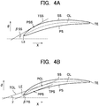
- FIGS. 4A and 4B are cross-sectional views taken along the line I-I in FIG. 3 , showing the cross-sectional shape, that is, airfoil, of the blade part AF at a position in the span direction (a position in the height direction of the blade part AF).
- the arrows X and ⁇ indicate the axial direction and the circumferential direction, respectively.
- the airfoil includes a concave pressure surface PS and a convex suction surface SS that extend between a leading edge LE and a trailing edge TE.
- a line segment connecting the leading edge LE and the trailing edge TE to each other is referred to as a chord.
- the length of the chord is referred to as a chord length, and the direction along the chord is referred to as a chord direction.
- pressure surface and suction surface which originally mean curved surfaces of the blade part, are used to refer to curved lines forming the contour of the airfoil in this specification.
- the airfoil is curved along a camber line (airfoil center line) CL, and the curve can be regarded as a change in blade surface angle ( ⁇ ) from the leading edge LE to the trailing edge TE.
- the blade surface angle of the suction surface SS is an angle formed by a tangent (TSS) to the suction surface SS at a point (PSS) and the axial direction (X).
- TSS tangent
- PSS point
- X axial direction
- the suction surface's blade surface angle at the leading edge LE will be referred to as a suction surface's inlet blade surface angle ( ⁇ SSin)
- ⁇ SSex suction surface's exit blade surface angle
- the blade surface angle of the pressure surface PS is an angle formed by a tangent (TPS) to the pressure surface PS at a point (PPS) and the axial direction (X).
- the suction surface's inlet blade surface angle ⁇ SSin is greater than the suction surface's exit blade surface angle ⁇ SSex, and the suction surface's blade surface angle ⁇ SS gradually decreases as it goes from the leading edge LE to the trailing edge TE.
- the pressure surface's blade surface angle ⁇ PS first temporarily increases from the value at the leading edge LE (that is, the tangent TPS rotates counterclockwise in the drawing) in a region near the leading edge LE and then gradually decreases (that is, the tangent TPS rotates clockwise in the drawing) as it goes toward the trailing edge TE. This is because the pressure surface PS locally curves outward in the region near the leading edge LE.
- a parameter that indicates the way of change of the suction surface's blade surface angle ⁇ SS that is, the suction surface's normalized blade surface angle ( ⁇ SS) is defined by the following formula (1).
- ⁇ SS ⁇ SSin ⁇ ⁇ SS / ⁇ SSin ⁇ ⁇ SSex
- a parameter that indicates the way of change of the pressure surface's blade surface angle ⁇ PS that is, the pressure surface's normalized blade surface angle ( ⁇ PS) is defined by the following formula (2).
- ⁇ PS ⁇ in ⁇ ⁇ PS / ⁇ in ⁇ ⁇ ex
- ⁇ denotes an angle formed by a tangent (TCL) to the camber line CL at a point (PCL) and the axial direction (X), that is, a camber line angle
- ⁇ in denotes a camber line angle at the leading edge LE, that is, an inlet camber line angle
- ⁇ ex denotes a camber line angle at the trailing edge TE, that is, an exit camber line angle.
- the camber line angle ⁇ is used for normalization, rather than the pressure surface's blade surface angle ⁇ PS at the leading edge LE and the trailing edge TE. This is because, on the pressure surface PS, the difference between the pressure surface's blade surface angle ⁇ PS at the leading edge LE and the pressure surface's blade surface angle ⁇ PS at the trailing edge TE (which corresponds to the denominator in the formula (1)) is very small, and therefore the value of ⁇ PS is too great, which is undesirable.
- the pressure surface's normalized blade surface angle ⁇ PS first temporarily decreases to a minimum as it goes from the leading edge LE toward the trailing edge TE, and then monotonically increases as it goes to the trailing edge TE.
- the sharpness of the change of the blade surface angle (or in other words, the magnitude of the curve of the airfoil) can be regarded as the sharpness of the change of the normalized blade surface angle.
- using the normalized blade surface angle allows comparison of the sharpness of the change of the blade surface angle between different blades.
- Patent Document 1 discloses a blade of a compressor that is reduced in loss by adjusting the curve of the airfoil.
- the angle formed by a tangent at a point on the camber (center line) of the airfoil and the axial direction is denoted as ⁇ ', and the same angles at the leading edge and the trailing edge are denoted as ⁇ in' and ⁇ ex', respectively, a point on the camber at which the parameter ( ⁇ ') defined by the following formula (3) equals to 0.5 is arranged within a predetermined range in the chord direction.
- ⁇ ′ ⁇ in ′ ⁇ ⁇ ′ / ⁇ in ′ ⁇ ⁇ ex ′
- Patent Document 1 International Publication No. WO 2016/024461
- An inter-blade flow channel formed between two blade parts located adjacent to each other in the circumferential direction is a diffused flow channel the area of which increases as it goes from the inlet side (upstream side) to the exit side (downstream side) of the blade. Therefore, the velocity of the flow decreases, that is, the flow decelerates, as the flow channel area increases as the air flows from the inlet side to the exit side of the blade (because the velocity of the flow flowing into the inter-blade flow channel for the stator vane of a fan or a compressor is generally subsonic).
- the velocity gradient of the flow near the wall surface is small, so that the shearing stress, that is, the frictional stress, on the wall surface is low.
- the velocity gradient of the flow near the wall surface is great, so that the frictional stress is high. This means that the larger the area in which the laminar boundary layer is formed (laminar flow area) and the smaller the area in which the turbulent boundary layer is formed (turbulent flow area) on the blade surface, the smaller the frictional drag on the blade becomes, and smaller the friction loss of the inter-blade flow becomes.
- the boundary layer over the blade surface transitions early (that is, on the upstream side) from the laminar state to the turbulent state, so that the laminar flow area is small, and therefore, the friction loss of the inter-blade flow is high.
- the region in which the rapid deceleration of the flow occurs is the region in which the flow channel area of the inter-blade flow channel sharply increases.
- the sharpness of the increase of the flow channel area of the inter-blade channel corresponds to the sharpness of the decrease of the blade surface angle. That is, if the blade surface angle sharply decreases at a location, in a region downstream of that location, the flow channel area of the inter-blade channel sharply increases, so that it is highly likely that the flow sharply decelerates and the transition of the boundary layer from the laminar state to the turbulent state occurs.
- the transition of the boundary layer over the blade surface can be delayed (that is, the transition location can be shifted to the downstream side) to enlarge the laminar flow area, and thereby reducing the friction loss of the inter-blade flow.
- the present disclosure has been devised based on the above considerations, and an object of the present disclosure is to provide a stator vane of a fan or compressor that is reduced in loss by appropriately controlling a deceleration of a flow around the blade to delay a transition of a boundary layer over a blade surface (that is, to shift the transition location to the downstream side) to enlarge a laminar flow area over the blade surface.
- a stator vane is a stator vane of a fan or compressor that is a component of a turbofan engine, wherein an airfoil, which is a cross section, of the stator vane at each location in a height direction is formed by a concave pressure surface and a convex suction surface each of which extends between a leading edge and a trailing edge of the stator vane, and in the cross section, provided that an angle formed by a tangent at a point on the suction surface and an axial direction of the turbofan engine is referred to as a suction surface's blade surface angle ( ⁇ SS), the suction surface's blade surface angle at the leading edge is referred to as a suction surface's inlet blade surface angle ( ⁇ SSin), the suction surface's blade surface angle at the trailing edge is referred to as a suction surface's exit blade surface angle ( ⁇ SSex), and a parameter ( ⁇ SS) defined by the formula (1) is
- the present disclosure provides a beneficial effect that the laminar flow area is enlarged and the friction loss is reduced by delaying the transition of the boundary layer over the blade surface from the laminar state to the turbulent state (that is, shifting the transition location to the downstream side).
- chord ratio (xc) which is a non-dimensional value, is the distance (x) from the leading edge measured in the chord direction divided by the chord length (c).
- the change rate of the pressure surface's blade surface angle preferably has an upper limit in order to maintain a boundary layer over the blade surface in a laminar state.
- a stator vane according to the embodiment of the present disclosure has an airfoil obtained by modifying the airfoil of the conventional stator vane based on the following principles.
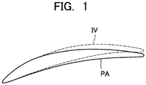
- FIG. 1 shows a cross-sectional shape (airfoil) IV, at a location in a span direction, of the stator vane according to the embodiment of the present disclosure provided as described above for comparison with the airfoil PA of the conventional stator vane.
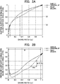
- FIGS. 2A to 2B show distributions in the chord direction of the normalized blade surface angle of the stator vane according to the embodiment of the present disclosure for comparison with the conventional stator vane.
- FIG. 2A shows a distribution of the suction surface's normalized blade surface angle
- FIG. 2B shows a distribution of the pressure surface's normalized blade surface angle.
- the vertical axis indicates the normalized blade surface angle
- the horizontal axis indicates the location in the chord direction
- the location in the chord direction is indicated in terms of chord ratio xc.
- the suction surface's normalized blade surface angle ⁇ SS at a location where the chord ratio is 0.05 is set to be equal to or less than 0.35 (see (a) in the graph), thereby keeping the maximum value of the flow velocity in a region near the location equal to or less than the same value for the conventional stator vane and at the same time making the change of the suction surface's normalized blade surface angle ⁇ SS in a region downstream of the location gentler, thereby reducing the deceleration in the region where the chord ratio is about 0.20 to 0.35.
- the upper limit value of the change rate (d( ⁇ PS)/dxc) in the chord direction of the pressure surface's normalized blade surface angle ( ⁇ PS) is set at 0.9, thereby preventing transition of the boundary layer to a turbulent state.
- the deceleration of the flow around the vane is more appropriately controlled by adjusting the way of change of the normalized blade surface angle, and as a result, the laminar flow area over the blade surface is enlarged, and loss is reduced.
- the transition location on the suction surface is a location where the chord ratio is 0.34, and the suction surface's normalized blade surface angle at the transition location is 0.62.
- the suction surface's normalized blade surface angle at a location where the chord ratio is 0.34 is equal to or less than 0.62.
- stator vane according to the embodiment of the present disclosure meets the following conditions.
- the suction surface's normalized blade surface angle ⁇ SS at a location where the chord ratio is 0.05 is equal to or less than 0.35.
- the suction surface's normalized blade surface angle ⁇ SS at a location where the chord ratio is 0.34 is equal to or less than 0.62.
- the change rate (d( ⁇ PS)/dxc) in the chord direction of the pressure surface's normalized blade surface angle ⁇ PS is equal to or less than 0.9.
- the blade according to the present disclosure has a wide variety of applications and can also be used as a stator vane of a compressor of a gas turbine other than the turbofan engine or a fan or compressor as a stand-alone device.
Landscapes
- Engineering & Computer Science (AREA)
- Mechanical Engineering (AREA)
- General Engineering & Computer Science (AREA)
- Physics & Mathematics (AREA)
- Fluid Mechanics (AREA)
- Chemical & Material Sciences (AREA)
- Combustion & Propulsion (AREA)
- Structures Of Non-Positive Displacement Pumps (AREA)
Abstract
Description
- The present disclosure relates to a stator vane of a fan or compressor that is a component of a turbofan engine. In particular, it relates to a stator vane of a fan or compressor that is reduced in loss by controlling deceleration of a flow around the blade and enlarging a laminar flow area over the blade surface.
- A fan or compressor that is a component of a turbofan engine is provided with a rotor blade and a stator vane.
FIG. 3 shows a stator vane as an example of the stator vane. Note that the terms "radial direction", "circumferential direction" and "axial direction" used in the following description coincide with the radial direction, the circumferential direction and the axial direction of a turbofan engine incorporating the stator vane, respectively. -
FIG. 3 is a schematic perspective view of a stator vane SV. The stator vane SV includes a blade part AF, and an outer band OB and an inner band IB. The blade part AF is a part that extends in the radial direction in an annular flow channel through which air as a working fluid flows. Such blade parts AF are disposed at regular intervals in the circumferential direction to form a cascade of blades. The outer band OB and the inner band IB are plate-like parts connected to a radially outer end and a radially inner end of the blade part AF, respectively. A plurality of such outer bands OB is arranged adjacent to each other in the circumferential direction, thereby forming an outer boundary surface of the annular flow channel described above, and a plurality of such inner bands IB is arranged adjacent to each other in the circumferential direction, thereby forming an inner boundary surface of the annular flow channel described above. - Both
FIGS. 4A and 4B are cross-sectional views taken along the line I-I inFIG. 3 , showing the cross-sectional shape, that is, airfoil, of the blade part AF at a position in the span direction (a position in the height direction of the blade part AF). In this drawing, the arrows X and θ indicate the axial direction and the circumferential direction, respectively. - The airfoil includes a concave pressure surface PS and a convex suction surface SS that extend between a leading edge LE and a trailing edge TE. A line segment connecting the leading edge LE and the trailing edge TE to each other is referred to as a chord. The length of the chord is referred to as a chord length, and the direction along the chord is referred to as a chord direction. Note that the terms "pressure surface" and "suction surface", which originally mean curved surfaces of the blade part, are used to refer to curved lines forming the contour of the airfoil in this specification.
- As shown in
FIGS. 4A and 4B , the airfoil is curved along a camber line (airfoil center line) CL, and the curve can be regarded as a change in blade surface angle (β) from the leading edge LE to the trailing edge TE. - As shown in
FIG. 4A , the blade surface angle of the suction surface SS, that is, the suction surface's blade surface angle (βSS) is an angle formed by a tangent (TSS) to the suction surface SS at a point (PSS) and the axial direction (X). The suction surface's blade surface angle at the leading edge LE will be referred to as a suction surface's inlet blade surface angle (βSSin), and the blade surface angle at the trailing edge TE will be referred to as a suction surface's exit blade surface angle (βSSex). - Similarly, as shown in
FIG. 4B , the blade surface angle of the pressure surface PS, that is, the pressure surface's blade surface angle (βPS) is an angle formed by a tangent (TPS) to the pressure surface PS at a point (PPS) and the axial direction (X). - In general, the suction surface's inlet blade surface angle βSSin is greater than the suction surface's exit blade surface angle βSSex, and the suction surface's blade surface angle βSS gradually decreases as it goes from the leading edge LE to the trailing edge TE.
- On the other hand, in general, the pressure surface's blade surface angle βPS first temporarily increases from the value at the leading edge LE (that is, the tangent TPS rotates counterclockwise in the drawing) in a region near the leading edge LE and then gradually decreases (that is, the tangent TPS rotates clockwise in the drawing) as it goes toward the trailing edge TE. This is because the pressure surface PS locally curves outward in the region near the leading edge LE.
- As a parameter that objectively indicates the way of change of the blade surface angle, a normalized blade surface angle is introduced.
- A parameter that indicates the way of change of the suction surface's blade surface angle βSS, that is, the suction surface's normalized blade surface angle (δSS) is defined by the following formula (1).

- As can be seen from the formula (1), the suction surface's normalized blade surface angle δSS is a parameter of the decrease of the suction surface's blade surface angle βSS at a point on the suction surface SS from the suction surface's blade surface angle at the leading edge LE (the suction surface's inlet blade surface angle βSSin) normalized with the total decrease of the suction surface's blade surface angle from the leading edge LE to the trailing edge TE (the suction surface's inlet blade surface angle βSSin minus the suction surface's exit blade surface angle βSSex), and monotonically increases as it goes from the leading edge LE (δSS = 0) to the trailing edge TE (δSS = 1).
- On the other hand, a parameter that indicates the way of change of the pressure surface's blade surface angle βPS, that is, the pressure surface's normalized blade surface angle (δPS) is defined by the following formula (2).

- As shown in
FIG. 4B , γ denotes an angle formed by a tangent (TCL) to the camber line CL at a point (PCL) and the axial direction (X), that is, a camber line angle, γin denotes a camber line angle at the leading edge LE, that is, an inlet camber line angle, and γex denotes a camber line angle at the trailing edge TE, that is, an exit camber line angle. - In the formula (2), the camber line angle γ is used for normalization, rather than the pressure surface's blade surface angle βPS at the leading edge LE and the trailing edge TE. This is because, on the pressure surface PS, the difference between the pressure surface's blade surface angle βPS at the leading edge LE and the pressure surface's blade surface angle βPS at the trailing edge TE (which corresponds to the denominator in the formula (1)) is very small, and therefore the value of δPS is too great, which is undesirable.
- According to the change of the pressure surface's blade surface angle βPS described above, the pressure surface's normalized blade surface angle δPS first temporarily decreases to a minimum as it goes from the leading edge LE toward the trailing edge TE, and then monotonically increases as it goes to the trailing edge TE.
- As can be seen, there is a correspondence between the change of the normalized blade surface angle from the leading edge LE to the trailing edge TE and the change of the blade surface angle, and therefore, the sharpness of the change of the blade surface angle (or in other words, the magnitude of the curve of the airfoil) can be regarded as the sharpness of the change of the normalized blade surface angle. In addition, using the normalized blade surface angle allows comparison of the sharpness of the change of the blade surface angle between different blades.
-
Patent Document 1 discloses a blade of a compressor that is reduced in loss by adjusting the curve of the airfoil. With the blade disclosed in the document, provided that the angle formed by a tangent at a point on the camber (center line) of the airfoil and the axial direction is denoted as β', and the same angles at the leading edge and the trailing edge are denoted as βin' and βex', respectively, a point on the camber at which the parameter (δ') defined by the following formula (3) equals to 0.5 is arranged within a predetermined range in the chord direction.
- Patent Document 1: International Publication No.
WO 2016/024461 - An inter-blade flow channel formed between two blade parts located adjacent to each other in the circumferential direction is a diffused flow channel the area of which increases as it goes from the inlet side (upstream side) to the exit side (downstream side) of the blade. Therefore, the velocity of the flow decreases, that is, the flow decelerates, as the flow channel area increases as the air flows from the inlet side to the exit side of the blade (because the velocity of the flow flowing into the inter-blade flow channel for the stator vane of a fan or a compressor is generally subsonic).
- In this process, at a location where the flow channel area sharply increases, a rapid deceleration of the flow occurs, and the boundary layer formed over the blade surface transitions from the laminar state to the turbulent state.
- In the laminar boundary layer, the velocity gradient of the flow near the wall surface is small, so that the shearing stress, that is, the frictional stress, on the wall surface is low. However, in the turbulent boundary layer, the velocity gradient of the flow near the wall surface is great, so that the frictional stress is high. This means that the larger the area in which the laminar boundary layer is formed (laminar flow area) and the smaller the area in which the turbulent boundary layer is formed (turbulent flow area) on the blade surface, the smaller the frictional drag on the blade becomes, and smaller the friction loss of the inter-blade flow becomes.
- Therefore, in designing the airfoil, it is necessary to ensure that the location where the boundary layer transitions from the laminar state to the turbulent state is as downstream as possible in order to make the laminar flow area as large as possible.
- With the conventional stator vane, the boundary layer over the blade surface transitions early (that is, on the upstream side) from the laminar state to the turbulent state, so that the laminar flow area is small, and therefore, the friction loss of the inter-blade flow is high.
- Detailed analysis of the velocity distribution of the flow around the conventional stator vane has shown that a rapid deceleration of the flow occurs in a relatively upstream area on the suction surface, and the boundary layer transitions in the area.
- As described above, it can be considered that the region in which the rapid deceleration of the flow occurs is the region in which the flow channel area of the inter-blade flow channel sharply increases. In this regard, the sharpness of the increase of the flow channel area of the inter-blade channel corresponds to the sharpness of the decrease of the blade surface angle. That is, if the blade surface angle sharply decreases at a location, in a region downstream of that location, the flow channel area of the inter-blade channel sharply increases, so that it is highly likely that the flow sharply decelerates and the transition of the boundary layer from the laminar state to the turbulent state occurs.
- As can be seen from the foregoing, if the deceleration of the flow around the blade is appropriately controlled by adjusting the sharpness of the decrease of the blade surface angle and thereby adjusting the sharpness of the increase of the flow channel area of the inter-blade flow channel, the transition of the boundary layer over the blade surface can be delayed (that is, the transition location can be shifted to the downstream side) to enlarge the laminar flow area, and thereby reducing the friction loss of the inter-blade flow.
- The present disclosure has been devised based on the above considerations, and an object of the present disclosure is to provide a stator vane of a fan or compressor that is reduced in loss by appropriately controlling a deceleration of a flow around the blade to delay a transition of a boundary layer over a blade surface (that is, to shift the transition location to the downstream side) to enlarge a laminar flow area over the blade surface.
- In order to solve the problem described above, a stator vane according to the present disclosure is a stator vane of a fan or compressor that is a component of a turbofan engine, wherein an airfoil, which is a cross section, of the stator vane at each location in a height direction is formed by a concave pressure surface and a convex suction surface each of which extends between a leading edge and a trailing edge of the stator vane, and in the cross section, provided that an angle formed by a tangent at a point on the suction surface and an axial direction of the turbofan engine is referred to as a suction surface's blade surface angle (βSS), the suction surface's blade surface angle at the leading edge is referred to as a suction surface's inlet blade surface angle (βSSin), the suction surface's blade surface angle at the trailing edge is referred to as a suction surface's exit blade surface angle (βSSex), and a parameter (δSS) defined by the formula (1) is referred to as a suction surface's normalized blade surface angle, provided that an angle formed by a tangent at a point on the pressure surface and the axial direction of the turbofan engine is referred to as a pressure surface's blade surface angle (βPS), an angle formed by a tangent at a point on a camber line of the airfoil and the axial direction of the turbofan engine is referred to as a camber line angle, the camber line angle at the leading edge is referred to as an inlet camber line angle (γin), the camber line angle at the trailing edge is referred to as an exit camber line angle (yex), and a parameter (δPS) defined by the formula (2) is referred to as a pressure surface's normalized blade surface angle, and provided that a line segment connecting the leading edge and the trailing edge is referred to as a chord, a length of the chord is referred to as a chord length (c), and a parameter (xc) defined as a distance (x) from a point on the pressure surface or suction surface to the leading edge measured in a direction parallel with the chord divided by the chord length (c) is referred to as a chord ratio, the suction surface's normalized blade surface angle at a location where the chord ratio is 0.05 is equal to or less than 0.35, the suction surface's normalized blade surface angle at a location where the chord ratio is 0.34 is equal to or less than 0.62, and a change rate (d(δPS)/dxc) in a chord direction of the pressure surface's normalized blade surface angle in a range of the chord ratio from 0 to 0.95 is equal to or less than 0.9.


- The present disclosure provides a beneficial effect that the laminar flow area is enlarged and the friction loss is reduced by delaying the transition of the boundary layer over the blade surface from the laminar state to the turbulent state (that is, shifting the transition location to the downstream side).
-
-
FIG. 1 is a schematic diagram for illustrating a cross-sectional shape (airfoil), at a location in a span direction, of a stator vane according to an embodiment of the present disclosure for comparison with a conventional stator vane. -
FIG. 2A is a graph showing a distribution in a chord direction of a suction surface's normalized blade surface angle of the stator vane according to the embodiment of the present disclosure, for comparison with the conventional stator vane. -
FIG. 2B is a graph showing a distribution in the chord direction of the pressure surface's normalized blade surface angle of the stator vane according to the embodiment of the present disclosure, for comparison with the conventional stator vane. -
FIG. 3 is a schematic perspective view of a stator vane of a turbofan engine. -
FIG. 4A is a cross-sectional view (a diagram showing a cross-sectional shape (airfoil) of a stator vane) taken along the line I-I inFIG. 3 for illustrating a definition of a suction surface's blade surface angle. -
FIG. 4B is a cross-sectional view (a diagram showing a cross-sectional shape (airfoil) of the stator vane) taken along the line I-I inFIG. 3 for illustrating a definition of a pressure surface's blade surface angle. - In the following, an embodiment of the present disclosure will be described in detail with reference to the drawings.
- With the conventional stator vane, a sharp deceleration of the flow occurs in a region where a chord ratio is from about 0.20 to 0.35 on the suction surface. This means that the suction surface's blade surface angle sharply decreases or, in other words, the suction surface's normalized blade surface angle sharply increases in the region. The chord ratio (xc), which is a non-dimensional value, is the distance (x) from the leading edge measured in the chord direction divided by the chord length (c).
- For the pressure surface, also with the conventional stator vane, the change rate of the pressure surface's blade surface angle preferably has an upper limit in order to maintain a boundary layer over the blade surface in a laminar state.
- In view of this, a stator vane according to the embodiment of the present disclosure has an airfoil obtained by modifying the airfoil of the conventional stator vane based on the following principles.
- (1) For the suction surface, in the region where the chord ratio is about 0.20 to 0.35, the change of the suction surface's blade surface angle is reduced in order to reduce the deceleration of the flow. To this end, in a region upstream of that region where the chord ratio is about 0.05, the change of the suction surface's blade surface angle is increased with the maximum value of the flow velocity in the region kept to be equal to or less than the same value for the conventional stator vane.
- (2) For the pressure surface, an upper limit is set for the change rate (d(δPS/dxc)) in the chord direction of the pressure surface's normalized blade surface angle (δPS).
-
FIG. 1 shows a cross-sectional shape (airfoil) IV, at a location in a span direction, of the stator vane according to the embodiment of the present disclosure provided as described above for comparison with the airfoil PA of the conventional stator vane.FIGS. 2A to 2B show distributions in the chord direction of the normalized blade surface angle of the stator vane according to the embodiment of the present disclosure for comparison with the conventional stator vane.FIG. 2A shows a distribution of the suction surface's normalized blade surface angle, andFIG. 2B shows a distribution of the pressure surface's normalized blade surface angle. In these drawings, the vertical axis indicates the normalized blade surface angle, the horizontal axis indicates the location in the chord direction, and the location in the chord direction is indicated in terms of chord ratio xc. - As shown in
FIG. 2A , on the suction surface, the suction surface's normalized blade surface angle δSS at a location where the chord ratio is 0.05 is set to be equal to or less than 0.35 (see (a) in the graph), thereby keeping the maximum value of the flow velocity in a region near the location equal to or less than the same value for the conventional stator vane and at the same time making the change of the suction surface's normalized blade surface angle δSS in a region downstream of the location gentler, thereby reducing the deceleration in the region where the chord ratio is about 0.20 to 0.35. - As shown in
FIG. 2B , on the pressure surface, in the range of the chord ratio from 0 to 0.95 shown by the arrow R in the drawing, the upper limit value of the change rate (d(δPS)/dxc) in the chord direction of the pressure surface's normalized blade surface angle (δPS) is set at 0.9, thereby preventing transition of the boundary layer to a turbulent state. - As can be seen from the above description, with the stator vane according to the embodiment of the present disclosure, compared with the conventional stator vane, the deceleration of the flow around the vane is more appropriately controlled by adjusting the way of change of the normalized blade surface angle, and as a result, the laminar flow area over the blade surface is enlarged, and loss is reduced.
- With the stator vane according to the embodiment of the present disclosure, the transition location on the suction surface is a location where the chord ratio is 0.34, and the suction surface's normalized blade surface angle at the transition location is 0.62.
- Therefore, it can be considered that, by setting the suction surface's blade surface angle at the transition location to be equal or less than the same value for the stator vane according to the embodiment of the present disclosure, the laminar flow area over the blade surface can be enlarged beyond the laminar flow area of the stator vane according to the embodiment of the present disclosure. Specifically, conditions for achieving this are as follows (see (b) in the graph in
FIG. 2A ). - The suction surface's normalized blade surface angle at a location where the chord ratio is 0.34 is equal to or less than 0.62.
- With the foregoing in mind, the stator vane according to the embodiment of the present disclosure meets the following conditions.
- On the suction surface, the suction surface's normalized blade surface angle δSS at a location where the chord ratio is 0.05 is equal to or less than 0.35.
- On the suction surface, the suction surface's normalized blade surface angle δSS at a location where the chord ratio is 0.34 is equal to or less than 0.62.
- On the pressure surface, in a range of the chord ratio from 0 to 0.95, the change rate (d(δPS)/dxc) in the chord direction of the pressure surface's normalized blade surface angle δPS is equal to or less than 0.9.
- Although an example where the blade according to the present disclosure is used as a stator vane of a fan that is a component of a turbofan engine has been described above, the blade according to the present disclosure has a wide variety of applications and can also be used as a stator vane of a compressor of a gas turbine other than the turbofan engine or a fan or compressor as a stand-alone device.
-
- SV
- stator vane
- AF
- blade part
- OB
- outer band
- IB
- inner band
- PS
- pressure surface
- SS
- suction surface
- LE
- leading edge
- TE
- trailing edge
- CL
- camber line
- β
- blade surface angle
- δ
- normalized blade surface angle
- γ
- camber line angle
Claims (1)
- A stator vane of a fan or compressor that is a component of a turbofan engine,
wherein an airfoil, which is a cross section, of the stator vane at each location in a height direction is formed by a concave pressure surface and a convex suction surface each of which extends between a leading edge and a trailing edge of the stator vane, and
in the cross section,
provided that an angle formed by a tangent at a point on the suction surface and an axial direction of the turbofan engine is referred to as a suction surface's blade surface angle (βSS), the suction surface's blade surface angle at the leading edge is referred to as a suction surface's inlet blade surface angle (βSSin), the suction surface's blade surface angle at the trailing edge is referred to as a suction surface's exit blade surface angle (βSSex), and a parameter (δSS) defined by the formula (1) is referred to as a suction surface's normalized blade surface angle:
a parameter (δPS) defined by the formula (2) is referred to as a pressure surface's normalized blade surface angle:
the suction surface's normalized blade surface angle at a location where the chord ratio is 0.05 is equal to or less than 0.35,
the suction surface's normalized blade surface angle at a location where the chord ratio is 0.34 is equal to or less than 0.62, and
a change rate (d(δPS)/dxc) in a chord direction of the pressure surface's normalized blade surface angle in a range of the chord ratio from 0 to 0.95 is equal to or less than 0.9.
Applications Claiming Priority (2)
| Application Number | Priority Date | Filing Date | Title |
|---|---|---|---|
| JP2017244148 | 2017-12-20 | ||
| PCT/JP2018/024392 WO2019123697A1 (en) | 2017-12-20 | 2018-06-27 | Fan and compressor stator blade |
Publications (2)
| Publication Number | Publication Date |
|---|---|
| EP3730801A1 true EP3730801A1 (en) | 2020-10-28 |
| EP3730801A4 EP3730801A4 (en) | 2021-05-05 |
Family
ID=66994527
Family Applications (1)
| Application Number | Title | Priority Date | Filing Date |
|---|---|---|---|
| EP18893318.8A Withdrawn EP3730801A4 (en) | 2017-12-20 | 2018-06-27 | Fan and compressor stator blade |
Country Status (4)
| Country | Link |
|---|---|
| US (1) | US11203945B2 (en) |
| EP (1) | EP3730801A4 (en) |
| JP (1) | JP6774044B2 (en) |
| WO (1) | WO2019123697A1 (en) |
Families Citing this family (2)
| Publication number | Priority date | Publication date | Assignee | Title |
|---|---|---|---|---|
| US12509988B2 (en) | 2024-06-14 | 2025-12-30 | Pratt & Whitney Canada Corp. | Turbine engine airfoil |
| CN118864789B (en) * | 2024-07-22 | 2025-10-03 | 武汉理工大学 | Benchmark weight driven decision-making method and device for reconstructing bending and torsional deformation blade model |
Family Cites Families (9)
| Publication number | Priority date | Publication date | Assignee | Title |
|---|---|---|---|---|
| JP4318940B2 (en) * | 2002-10-08 | 2009-08-26 | 本田技研工業株式会社 | Compressor airfoil |
| DE102005042115A1 (en) * | 2005-09-05 | 2007-03-08 | Rolls-Royce Deutschland Ltd & Co Kg | Blade of a fluid flow machine with block-defined profile skeleton line |
| DE102006055869A1 (en) * | 2006-11-23 | 2008-05-29 | Rolls-Royce Deutschland Ltd & Co Kg | Rotor and guide blades designing method for turbo-machine i.e. gas turbine engine, involves running skeleton curve in profile section in sectional line angle distribution area lying between upper and lower limit curves |
| DE102009033593A1 (en) * | 2009-07-17 | 2011-01-20 | Rolls-Royce Deutschland Ltd & Co Kg | Engine blade with excessive leading edge load |
| US9309769B2 (en) * | 2010-12-28 | 2016-04-12 | Rolls-Royce Corporation | Gas turbine engine airfoil shaped component |
| WO2015175044A2 (en) * | 2014-02-19 | 2015-11-19 | United Technologies Corporation | Gas turbine engine airfoil |
| JP6468414B2 (en) | 2014-08-12 | 2019-02-13 | 株式会社Ihi | Compressor vane, axial compressor, and gas turbine |
| FR3049013B1 (en) * | 2016-03-16 | 2019-11-22 | Safran Aircraft Engines | DAWN OF RECTIFIER |
| EP3633207A4 (en) * | 2017-05-24 | 2021-06-23 | IHI Corporation | Blade for fan and compressor |
-
2018
- 2018-06-27 EP EP18893318.8A patent/EP3730801A4/en not_active Withdrawn
- 2018-06-27 JP JP2019560022A patent/JP6774044B2/en active Active
- 2018-06-27 WO PCT/JP2018/024392 patent/WO2019123697A1/en not_active Ceased
-
2020
- 2020-06-05 US US16/893,556 patent/US11203945B2/en active Active
Also Published As
| Publication number | Publication date |
|---|---|
| WO2019123697A1 (en) | 2019-06-27 |
| EP3730801A4 (en) | 2021-05-05 |
| JP6774044B2 (en) | 2020-10-21 |
| US11203945B2 (en) | 2021-12-21 |
| US20200300102A1 (en) | 2020-09-24 |
| JPWO2019123697A1 (en) | 2020-04-16 |
Similar Documents
| Publication | Publication Date | Title |
|---|---|---|
| RU2711204C2 (en) | Gas turbine engine airflow straightening assembly and gas turbine engine comprising such unit | |
| US11333167B2 (en) | Method of designing blade of axial flow fluid machine and blade | |
| EP1798377B1 (en) | Airfoil embodying mixed loading conventions | |
| US11125085B2 (en) | Blade of fan or compressor | |
| CN106133277B (en) | The variable rib of guiding blade extension | |
| EP2159398A2 (en) | Separation-resistant inlet duct for mid-turbine frames | |
| EP3048251B1 (en) | Turbine bucket for control of wheelspace purge air | |
| EP2189663A2 (en) | Centrifugal compressor | |
| US9644637B2 (en) | Axial compressor | |
| CN105829653A (en) | Turbomachine component or collection of components and associated turbomachine | |
| EP3922817A1 (en) | Method for designing blade for axial flow type fan, compressor and turbine, and blade obtained by means of said design | |
| EA028485B1 (en) | Centrifugal machine | |
| US11203945B2 (en) | Stator vane of fan or compressor | |
| EP3098383B1 (en) | Compressor airfoil with compound leading edge profile | |
| EP3106615B1 (en) | Axial turbine | |
| EP3163020B1 (en) | Turbine rotor blade cascade, turbine stage and axial flow turbine | |
| JPH10331791A (en) | Blade for axial flow compressor and axial flow compressor applying the blade | |
| US10837450B2 (en) | Compressor rotor blade, compressor, and method for profiling the compressor rotor blade | |
| EP4206440A1 (en) | Axial-flow fan, method for modifying blade for compressor and turbine, and blade obtained according to said design | |
| US11661854B2 (en) | Stator vane segment of axial turbine | |
| JP7273363B2 (en) | axial compressor | |
| US10570743B2 (en) | Turbomachine having an annulus enlargment and airfoil |
Legal Events
| Date | Code | Title | Description |
|---|---|---|---|
| STAA | Information on the status of an ep patent application or granted ep patent |
Free format text: STATUS: THE INTERNATIONAL PUBLICATION HAS BEEN MADE |
|
| PUAI | Public reference made under article 153(3) epc to a published international application that has entered the european phase |
Free format text: ORIGINAL CODE: 0009012 |
|
| STAA | Information on the status of an ep patent application or granted ep patent |
Free format text: STATUS: REQUEST FOR EXAMINATION WAS MADE |
|
| 17P | Request for examination filed |
Effective date: 20200720 |
|
| AK | Designated contracting states |
Kind code of ref document: A1 Designated state(s): AL AT BE BG CH CY CZ DE DK EE ES FI FR GB GR HR HU IE IS IT LI LT LU LV MC MK MT NL NO PL PT RO RS SE SI SK SM TR |
|
| AX | Request for extension of the european patent |
Extension state: BA ME |
|
| DAV | Request for validation of the european patent (deleted) | ||
| DAX | Request for extension of the european patent (deleted) | ||
| A4 | Supplementary search report drawn up and despatched |
Effective date: 20210408 |
|
| RIC1 | Information provided on ipc code assigned before grant |
Ipc: F04D 29/54 20060101AFI20210331BHEP Ipc: F02C 7/00 20060101ALI20210331BHEP Ipc: F04D 19/02 20060101ALI20210331BHEP Ipc: F01D 5/14 20060101ALI20210331BHEP |
|
| STAA | Information on the status of an ep patent application or granted ep patent |
Free format text: STATUS: EXAMINATION IS IN PROGRESS |
|
| 17Q | First examination report despatched |
Effective date: 20220826 |
|
| STAA | Information on the status of an ep patent application or granted ep patent |
Free format text: STATUS: THE APPLICATION HAS BEEN WITHDRAWN |
|
| 18W | Application withdrawn |
Effective date: 20221205 |