EP3730742A1 - Vane core assemblies and methods - Google Patents
Vane core assemblies and methods Download PDFInfo
- Publication number
- EP3730742A1 EP3730742A1 EP20169674.7A EP20169674A EP3730742A1 EP 3730742 A1 EP3730742 A1 EP 3730742A1 EP 20169674 A EP20169674 A EP 20169674A EP 3730742 A1 EP3730742 A1 EP 3730742A1
- Authority
- EP
- European Patent Office
- Prior art keywords
- platform
- passage
- airfoil
- rail
- vane assembly
- Prior art date
- Legal status (The legal status is an assumption and is not a legal conclusion. Google has not performed a legal analysis and makes no representation as to the accuracy of the status listed.)
- Granted
Links
Images



Classifications
-
- F—MECHANICAL ENGINEERING; LIGHTING; HEATING; WEAPONS; BLASTING
- F01—MACHINES OR ENGINES IN GENERAL; ENGINE PLANTS IN GENERAL; STEAM ENGINES
- F01D—NON-POSITIVE DISPLACEMENT MACHINES OR ENGINES, e.g. STEAM TURBINES
- F01D9/00—Stators
- F01D9/06—Fluid supply conduits to nozzles or the like
- F01D9/065—Fluid supply or removal conduits traversing the working fluid flow, e.g. for lubrication-, cooling-, or sealing fluids
-
- F—MECHANICAL ENGINEERING; LIGHTING; HEATING; WEAPONS; BLASTING
- F01—MACHINES OR ENGINES IN GENERAL; ENGINE PLANTS IN GENERAL; STEAM ENGINES
- F01D—NON-POSITIVE DISPLACEMENT MACHINES OR ENGINES, e.g. STEAM TURBINES
- F01D5/00—Blades; Blade-carrying members; Heating, heat-insulating, cooling or antivibration means on the blades or the members
- F01D5/12—Blades
- F01D5/14—Form or construction
- F01D5/18—Hollow blades, i.e. blades with cooling or heating channels or cavities; Heating, heat-insulating or cooling means on blades
- F01D5/186—Film cooling
-
- B—PERFORMING OPERATIONS; TRANSPORTING
- B22—CASTING; POWDER METALLURGY
- B22C—FOUNDRY MOULDING
- B22C9/00—Moulds or cores; Moulding processes
- B22C9/10—Cores; Manufacture or installation of cores
-
- B—PERFORMING OPERATIONS; TRANSPORTING
- B22—CASTING; POWDER METALLURGY
- B22C—FOUNDRY MOULDING
- B22C9/00—Moulds or cores; Moulding processes
- B22C9/22—Moulds for peculiarly-shaped castings
- B22C9/24—Moulds for peculiarly-shaped castings for hollow articles
-
- F—MECHANICAL ENGINEERING; LIGHTING; HEATING; WEAPONS; BLASTING
- F01—MACHINES OR ENGINES IN GENERAL; ENGINE PLANTS IN GENERAL; STEAM ENGINES
- F01D—NON-POSITIVE DISPLACEMENT MACHINES OR ENGINES, e.g. STEAM TURBINES
- F01D25/00—Component parts, details, or accessories, not provided for in, or of interest apart from, other groups
- F01D25/08—Cooling; Heating; Heat-insulation
- F01D25/12—Cooling
-
- F—MECHANICAL ENGINEERING; LIGHTING; HEATING; WEAPONS; BLASTING
- F01—MACHINES OR ENGINES IN GENERAL; ENGINE PLANTS IN GENERAL; STEAM ENGINES
- F01D—NON-POSITIVE DISPLACEMENT MACHINES OR ENGINES, e.g. STEAM TURBINES
- F01D5/00—Blades; Blade-carrying members; Heating, heat-insulating, cooling or antivibration means on the blades or the members
- F01D5/12—Blades
- F01D5/14—Form or construction
- F01D5/18—Hollow blades, i.e. blades with cooling or heating channels or cavities; Heating, heat-insulating or cooling means on blades
-
- F—MECHANICAL ENGINEERING; LIGHTING; HEATING; WEAPONS; BLASTING
- F01—MACHINES OR ENGINES IN GENERAL; ENGINE PLANTS IN GENERAL; STEAM ENGINES
- F01D—NON-POSITIVE DISPLACEMENT MACHINES OR ENGINES, e.g. STEAM TURBINES
- F01D9/00—Stators
- F01D9/02—Nozzles; Nozzle boxes; Stator blades; Guide conduits, e.g. individual nozzles
-
- F—MECHANICAL ENGINEERING; LIGHTING; HEATING; WEAPONS; BLASTING
- F01—MACHINES OR ENGINES IN GENERAL; ENGINE PLANTS IN GENERAL; STEAM ENGINES
- F01D—NON-POSITIVE DISPLACEMENT MACHINES OR ENGINES, e.g. STEAM TURBINES
- F01D9/00—Stators
- F01D9/02—Nozzles; Nozzle boxes; Stator blades; Guide conduits, e.g. individual nozzles
- F01D9/04—Nozzles; Nozzle boxes; Stator blades; Guide conduits, e.g. individual nozzles forming ring or sector
- F01D9/041—Nozzles; Nozzle boxes; Stator blades; Guide conduits, e.g. individual nozzles forming ring or sector using blades
-
- F—MECHANICAL ENGINEERING; LIGHTING; HEATING; WEAPONS; BLASTING
- F01—MACHINES OR ENGINES IN GENERAL; ENGINE PLANTS IN GENERAL; STEAM ENGINES
- F01D—NON-POSITIVE DISPLACEMENT MACHINES OR ENGINES, e.g. STEAM TURBINES
- F01D9/00—Stators
- F01D9/02—Nozzles; Nozzle boxes; Stator blades; Guide conduits, e.g. individual nozzles
- F01D9/04—Nozzles; Nozzle boxes; Stator blades; Guide conduits, e.g. individual nozzles forming ring or sector
- F01D9/047—Nozzle boxes
-
- F—MECHANICAL ENGINEERING; LIGHTING; HEATING; WEAPONS; BLASTING
- F01—MACHINES OR ENGINES IN GENERAL; ENGINE PLANTS IN GENERAL; STEAM ENGINES
- F01D—NON-POSITIVE DISPLACEMENT MACHINES OR ENGINES, e.g. STEAM TURBINES
- F01D5/00—Blades; Blade-carrying members; Heating, heat-insulating, cooling or antivibration means on the blades or the members
- F01D5/12—Blades
- F01D5/14—Form or construction
- F01D5/18—Hollow blades, i.e. blades with cooling or heating channels or cavities; Heating, heat-insulating or cooling means on blades
- F01D5/187—Convection cooling
-
- F—MECHANICAL ENGINEERING; LIGHTING; HEATING; WEAPONS; BLASTING
- F01—MACHINES OR ENGINES IN GENERAL; ENGINE PLANTS IN GENERAL; STEAM ENGINES
- F01D—NON-POSITIVE DISPLACEMENT MACHINES OR ENGINES, e.g. STEAM TURBINES
- F01D9/00—Stators
- F01D9/06—Fluid supply conduits to nozzles or the like
-
- F—MECHANICAL ENGINEERING; LIGHTING; HEATING; WEAPONS; BLASTING
- F05—INDEXING SCHEMES RELATING TO ENGINES OR PUMPS IN VARIOUS SUBCLASSES OF CLASSES F01-F04
- F05D—INDEXING SCHEME FOR ASPECTS RELATING TO NON-POSITIVE-DISPLACEMENT MACHINES OR ENGINES, GAS-TURBINES OR JET-PROPULSION PLANTS
- F05D2230/00—Manufacture
- F05D2230/20—Manufacture essentially without removing material
- F05D2230/21—Manufacture essentially without removing material by casting
- F05D2230/211—Manufacture essentially without removing material by casting by precision casting, e.g. microfusing or investment casting
-
- F—MECHANICAL ENGINEERING; LIGHTING; HEATING; WEAPONS; BLASTING
- F05—INDEXING SCHEMES RELATING TO ENGINES OR PUMPS IN VARIOUS SUBCLASSES OF CLASSES F01-F04
- F05D—INDEXING SCHEME FOR ASPECTS RELATING TO NON-POSITIVE-DISPLACEMENT MACHINES OR ENGINES, GAS-TURBINES OR JET-PROPULSION PLANTS
- F05D2240/00—Components
- F05D2240/80—Platforms for stationary or moving blades
- F05D2240/81—Cooled platforms
-
- F—MECHANICAL ENGINEERING; LIGHTING; HEATING; WEAPONS; BLASTING
- F05—INDEXING SCHEMES RELATING TO ENGINES OR PUMPS IN VARIOUS SUBCLASSES OF CLASSES F01-F04
- F05D—INDEXING SCHEME FOR ASPECTS RELATING TO NON-POSITIVE-DISPLACEMENT MACHINES OR ENGINES, GAS-TURBINES OR JET-PROPULSION PLANTS
- F05D2260/00—Function
- F05D2260/20—Heat transfer, e.g. cooling
- F05D2260/202—Heat transfer, e.g. cooling by film cooling
-
- F—MECHANICAL ENGINEERING; LIGHTING; HEATING; WEAPONS; BLASTING
- F05—INDEXING SCHEMES RELATING TO ENGINES OR PUMPS IN VARIOUS SUBCLASSES OF CLASSES F01-F04
- F05D—INDEXING SCHEME FOR ASPECTS RELATING TO NON-POSITIVE-DISPLACEMENT MACHINES OR ENGINES, GAS-TURBINES OR JET-PROPULSION PLANTS
- F05D2260/00—Function
- F05D2260/20—Heat transfer, e.g. cooling
- F05D2260/204—Heat transfer, e.g. cooling by the use of microcircuits
-
- F—MECHANICAL ENGINEERING; LIGHTING; HEATING; WEAPONS; BLASTING
- F05—INDEXING SCHEMES RELATING TO ENGINES OR PUMPS IN VARIOUS SUBCLASSES OF CLASSES F01-F04
- F05D—INDEXING SCHEME FOR ASPECTS RELATING TO NON-POSITIVE-DISPLACEMENT MACHINES OR ENGINES, GAS-TURBINES OR JET-PROPULSION PLANTS
- F05D2260/00—Function
- F05D2260/20—Heat transfer, e.g. cooling
- F05D2260/205—Cooling fluid recirculation, i.e. after cooling one or more components is the cooling fluid recovered and used elsewhere for other purposes
-
- Y—GENERAL TAGGING OF NEW TECHNOLOGICAL DEVELOPMENTS; GENERAL TAGGING OF CROSS-SECTIONAL TECHNOLOGIES SPANNING OVER SEVERAL SECTIONS OF THE IPC; TECHNICAL SUBJECTS COVERED BY FORMER USPC CROSS-REFERENCE ART COLLECTIONS [XRACs] AND DIGESTS
- Y02—TECHNOLOGIES OR APPLICATIONS FOR MITIGATION OR ADAPTATION AGAINST CLIMATE CHANGE
- Y02T—CLIMATE CHANGE MITIGATION TECHNOLOGIES RELATED TO TRANSPORTATION
- Y02T50/00—Aeronautics or air transport
- Y02T50/60—Efficient propulsion technologies, e.g. for aircraft
Definitions
- a gas turbine engine typically includes a fan section, a compressor section, a combustor section and a turbine section. Air entering the compressor section is compressed and delivered into the combustion section where it is mixed with fuel and ignited to generate a high-energy exhaust gas flow. The high-energy exhaust gas flow expands through the turbine section to drive the compressor and the fan section.
- the compressor section typically includes low and high pressure compressors, and the turbine section includes low and high pressure turbines.
- the high pressure turbine drives the high pressure compressor through an outer shaft to form a high spool
- the low pressure turbine drives the low pressure compressor through an inner shaft to form a low spool.
- the fan section may also be driven by the low inner shaft.
- a gas turbine engine includes a fan section driven by the low spool such that the low pressure compressor, low pressure turbine and fan section rotate at a common speed in a common direction.
- many of the components in a gas turbine engine see very high temperatures. Thus, it is known to supply cooling air to various components such as in the turbine section and/or compressor section.
- a gas turbine engine comprising a compressor section rotatable about an axis, a combustor in fluid communication with the compressor section, and a turbine section in fluid communication with the combustor.
- the turbine section includes a vane assembly including a radially outer platform with respect to the axis.
- a first airfoil extends from the radially outer platform to a radially inner platform.
- a rail extends radially inward from the inner platform, and a connected passage includes an airfoil passage within the first airfoil.
- a platform passage is located within the inner platform, and a rail passage is located within the rail. The airfoil passage, the platform passage, and the rail passage are fluidly connected.
- a second airfoil extends from the radially outer platform to the radially inner platform.
- a second connected passage includes a second airfoil passage within the second airfoil.
- a second platform passage is located within the inner platform, and a second rail passage is located within the rail. The second airfoil passage, the second platform passage, and the second rail passage are fluidly connected.
- a plurality of cooling holes extend from the platform passage to a gaspath surface of the inner platform.
- the plurality of cooling holes extend toward a trailing edge of the platform as they extend toward the gaspath surface.
- the airfoil passage forms a leading edge cavity and a second cavity spaced toward a trailing edge of the airfoil from the leading edge cavity.
- the gas turbine engine includes a second rail, and the first rail is axially forward of the second rail with respect to a core flow path of the gas turbine engine.
- a cooling air source is configured to supply cooling air from the outer platform through the airfoil passage, and to the platform passage.
- a plurality of cooling holes extend from the platform passage to a gaspath surface of the inner platform, and are configured to allow at least a portion of the cooling air in the platform passage to exit through the plurality of cooling holes.
- the turbine includes a first row of vanes, a second row of vanes aft of the first row of vanes, and a row of blades axially between the first row of vanes and second row of vanes.
- the second row of vanes include the vane assembly.
- the second row of vanes include a second vane assembly identical to the vane assembly.
- a vane assembly for a gas turbine engine comprising an outer platform, an inner platform, a first airfoil that extends from the outer platform to the inner platform, and a rail that extends from the inner platform in a direction away from the first airfoil.
- a connected passage includes an airfoil passage within the first airfoil, a platform passage within the inner platform, and a rail passage within the rail. The airfoil passage, the platform passage, and the rail passage are fluidly connected.
- a plurality of cooling holes extend from the platform passage to a gaspath surface of the inner platform.
- a second airfoil extends from the outer platform to the inner platform.
- the platform passage is aligned circumferentially between a pressure side of the first airfoil and a suction side of the second airfoil.
- a second airfoil extends from the outer platform to the inner platform.
- a second connected passage includes a second airfoil passage within the second airfoil.
- a second platform passage is located within the inner platform, and a second rail passage is located within the rail. The second airfoil passage, the second platform passage, and the second rail passage are fluidly connected.
- a second airfoil extends from the outer platform to the inner platform.
- the platform passage is aligned circumferentially between a pressure side of the first airfoil and a suction side of the second airfoil.
- the second platform passage is aligned circumferentially between a pressure side of the second airfoil and a mate face of the platform.
- the plurality of cooling holes extend toward a trailing edge of the platform as they extend toward the gas path surface.
- a method of manufacturing a vane assembly for a gas turbine engine comprising forming a ceramic core, which includes an airfoil core, a platform core, and a rail core, and casting a vane assembly around the core.
- the vane assembly includes an outer platform and an inner platform.
- An airfoil extends from the outer platform to the inner platform, and a rail extends radially inward from the inner platform.
- the airfoil core forms a first passage within the airfoil
- the platform core forms a second passage within the inner platform
- the rail core forms a third passage within the rail.
- the casting step includes forming a wax pattern around the ceramic core, forming a dipped ceramic shell around the wax pattern, removing the wax pattern to form a void, and then casting the vane assembly in the void.
- the core is destroyed after the casting step.
- a plurality of cooling holes are machined from the second passage to a gaspath surface of the inner platform.
- the plurality of cooling holes extend toward a trailing edge of the platform as they extend toward the gas path surface.
- FIG. 1 schematically illustrates a gas turbine engine 20.
- the gas turbine engine 20 is disclosed herein as a two-spool turbofan that generally incorporates a fan section 22, a compressor section 24, a combustor section 26 and a turbine section 28.
- the fan section 22 drives air along a bypass flow path B in a bypass duct defined within a nacelle 18, and also drives air along a core flow path C for compression and communication into the combustor section 26 then expansion through the turbine section 28.
- FIG. 1 schematically illustrates a gas turbine engine 20.
- the gas turbine engine 20 is disclosed herein as a two-spool turbofan that generally incorporates a fan section 22, a compressor section 24, a combustor section 26 and a turbine section 28.
- the fan section 22 drives air along a bypass flow path B in a bypass duct defined within a nacelle 18, and also drives air along a core flow path C for compression and communication into the combustor section 26 then expansion through the turbine section 28.
- FIG. 1 schematic
- the exemplary engine 20 generally includes a low speed spool 30 and a high speed spool 32 mounted for rotation about an engine central longitudinal axis A relative to an engine static structure 36 via several bearing systems 38. It should be understood that various bearing systems 38 at various locations may alternatively or additionally be provided, and the location of bearing systems 38 may be varied as appropriate to the application.
- the low speed spool 30 generally includes an inner shaft 40 that interconnects, a first (or low) pressure compressor 44 and a first (or low) pressure turbine 46.
- the inner shaft 40 is connected to a fan section 22 through a speed change mechanism, which in exemplary gas turbine engine 20 is illustrated as a geared architecture 48 to drive fan blades 42 at a lower speed than the low speed spool 30.
- the high speed spool 32 includes an outer shaft 50 that interconnects a second (or high) pressure compressor 52 and a second (or high) pressure turbine 54.
- a combustor 56 is arranged in exemplary gas turbine 20 between the high pressure compressor 52 and the high pressure turbine 54.
- a mid-turbine frame 58 of the engine static structure 36 may be arranged generally between the high pressure turbine 54 and the low pressure turbine 46.
- the mid-turbine frame 58 further supports bearing systems 38 in the turbine section 28.
- the inner shaft 40 and the outer shaft 50 are concentric and rotate via bearing systems 38 about the engine central longitudinal axis A which is collinear with their longitudinal axes.
- the core airflow is compressed by the low pressure compressor 44 then the high pressure compressor 52, mixed and burned with fuel in the combustor 56, then expanded over the high pressure turbine 54 and low pressure turbine 46.
- the mid-turbine frame 58 includes airfoils 60 which are in the core airflow path C.
- the turbines 46, 54 rotationally drive the respective low speed spool 30 and high speed spool 32 in response to the expansion.
- gear system 48 may be located aft of the low pressure compressor 44 and the fan blades 42 may be positioned forward or aft of the location of the geared architecture 48 or even aft of turbine section 28.
- the engine 20 in one example is a high-bypass geared aircraft engine.
- the engine 20 bypass ratio is greater than about six, with an example embodiment being greater than about ten
- the geared architecture 48 is an epicyclic gear train, such as a planetary gear system or other gear system, with a gear reduction ratio of greater than about 2.3 and the low pressure turbine 46 has a pressure ratio that is greater than about five.
- the engine 20 bypass ratio is greater than about ten
- the fan diameter is significantly larger than that of the low pressure compressor 44
- the low pressure turbine 46 has a pressure ratio that is greater than about five.
- Low pressure turbine 46 pressure ratio is pressure measured prior to inlet of low pressure turbine 46 as related to the pressure at the outlet of the low pressure turbine 46 prior to an exhaust nozzle.
- the geared architecture 48 may be an epicycle gear train, such as a planetary gear system or other gear system, with a gear reduction ratio of greater than about 2.3:1 and less than about 5:1. It should be understood, however, that the above parameters are only exemplary of one embodiment of a geared architecture engine and that the present invention is applicable to other gas turbine engines but not limited to including direct drive turbofans.
- the fan section 22 of the engine 20 is designed for a particular flight condition -- typically cruise at about 0.8 Mach and about 35,000 feet (10,668 meters).
- the flight condition of 0.8 Mach and 35,000 ft (10,668 meters), with the engine at its best fuel consumption - also known as "bucket cruise Thrust Specific Fuel Consumption ('TSFC')" - is the industry standard parameter of lbm of fuel being burned divided by lbf of thrust the engine produces at that minimum point.
- "Low fan pressure ratio” is the pressure ratio across the fan blade alone, without a Fan Exit Guide Vane (“FEGV”) system.
- the low fan pressure ratio as disclosed herein according to one non-limiting embodiment is less than about 1.45.
- the "Low corrected fan tip speed” as disclosed herein according to one non-limiting embodiment is less than about 1150 ft / second (350.5 meters/second).
- the example gas turbine engine includes the fan section 22 that comprises in one non-limiting embodiment less than about 26 fan blades 42. In another non-limiting embodiment, the fan section 22 includes less than about 20 fan blades 42. Moreover, in one disclosed embodiment the low pressure turbine 46 includes no more than about 6 turbine rotors schematically indicated at 34. In another non-limiting example embodiment the low pressure turbine 46 includes about 3 turbine rotors. A ratio between the number of fan blades 42 and the number of low pressure turbine rotors is between about 3.3 and about 8.6. The example low pressure turbine 46 provides the driving power to rotate the fan section 22 and therefore the relationship between the number of turbine rotors 34 in the low pressure turbine 46 and the number of blades 42 in the fan section 22 disclose an example gas turbine engine 20 with increased power transfer efficiency.
- FIG 2 schematically illustrates an example section 62 of the high pressure turbine 54 ( Figure 1 ) of the example gas turbine engine 20.
- the section 62 includes a first row of stator vanes 63 and a second row of stator vanes 64.
- a row of turbine blades 65 is axially between the first row of stator vanes 63 and the second row of stator vanes 64 with respect to the axis A.
- the first row of stator vanes 63 is immediately adjacent the combustor 56 with respect to the core flow path C, as shown schematically.
- the second row of stator vanes 64 includes a plurality of circumferentially spaced airfoils 66 extending radially between a radially outer platform 68 and a radially inner platform 70.
- Each airfoil 66 defines a leading edge 69 and a trailing edge 71 with respect to the core flow path C.
- a forward rail 72 and aft rail 74 may extend radially inward from each radially inner platform 70.
- the radially inner platform 70 includes a gaspath surface 78 that partially bounds the core flow path C. While the disclosed examples relate to improved cooling of the radially inner platforms 70 in the second row of stator vanes 64 in the high pressure turbine 54, other platforms, stages, and/or vane assemblies may benefit from this disclosure.
- Figure 3 illustrates a vane assembly 76 from the second row of stator vanes 64 shown in Figure 2 .
- the second row of stator vanes 64 includes a plurality of circumferentially adjacent vane assemblies or segments 76.
- the circumferentially adjacent vane assemblies 76 may be identical.
- the example vane assembly 76 includes an outer platform 68, an inner platform 70, and two airfoils 66A, 66B extending radially between.
- Other vane assemblies may benefit from this disclosure, including assemblies with a single airfoil per inner and outer platforms.
- the inner platform 70 extends circumferentially between a first mate face 77 and a second mate face 79, and axially (with respect to axis A in Figure 2 ) from a leading platform edge 80 to a trailing platform edge 82.
- the first mate face 77 is configured to mate with the second mate face 79 of a circumferentially adjacent vane assembly 76.
- the airfoils 66A, 66B include respective suction sides 85A, 85B and pressure sides 86A, 86B.
- Applicant has identified areas 84A, 84B of the gaspath surface 78 as regions needing enhanced cooling.
- the area 84A is circumferentially between the pressure side 86A and the suction side 85B and nearer the leading edge 80 than the trailing edge 82.
- the areas 84A, 84B are in the forward 50% of the axial length of the platform 70.
- the area 84B is circumferentially between the pressure side 86B and the mate face 79 and nearer the leading edge 80 than the trailing edge 82.
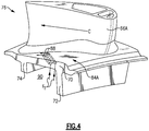
- FIG 4 illustrates a portion of the vane assembly 76 of Figure 3 .
- cooling holes 88 on the inner platform 70 are fed by pressurized air from a cavity 90 between the forward rail 72 and the aft rail 74, as a result of the pressure ratio between the core flow path C and the pressure under the inner platform 70, i.e., the pressure of air F1 is greater than the pressure in the core flow path C at the location of cooling holes 88.
- the air F1 is bled off the high pressure compressor 52 (See Figure 1 ).
- the air F1 may be plumbed to an outer diameter of the vane 76, through cores of the airfoils 66A, 66B of the vane 76 (see Figure 3 ), and to the cavity 90.
- the pressure of air F1 in the cavity 90 is less than the core flow path C pressure at the areas 84A, 84B and therefore cooling holes from the cavity 90 in this region would ingest air from the core flow path C.
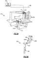
- FIG. 5A illustrates a portion of a novel vane assembly 176 with a section cut through the region 184A. It should be understood that like reference numerals identify corresponding or similar elements throughout the several drawings.
- a connected passage 191 is provided in the vane assembly 176 and includes an airfoil passage 192 within the airfoil 166A, a platform passage 193 within the inner platform 170, and a rail passage 194 within the forward rail 172.
- the airfoil passage 192, the platform passage 193, and the rail passage 194 form fluidly connected passage 191 such that the portions 192, 193, 194 are in fluid communication.
- the leading edge of the platform passage 193 is aft of the leading edge of the airfoil 166A.
- the airfoil passage 192 includes a leading edge cavity 192A and a second cavity 192B spaced toward the trailing edge from the leading edge cavity 192A and in fluid communication with the leading edge cavity 192A.
- the platform passage 193 is not in fluid communication with passages in the airfoil 166A other than passages 192A, 192B
- pressurized air is fed from a cooling air source 199 to supply cooling air through the outer platform 168, radially inward through the airfoil passage 192, and to the platform passage 193.
- the air F2 is compressor exit bypass air.
- the air F2 has at least 35% greater pressure than the air F1.
- At least a portion of the cooling air may exit the platform passage 193 radially outward through cooling holes 188 located at the area 184A.
- the holes 88 of Figure 4 may also be included in the vane assembly 176.
- the cooling holes 188 extend from the platform passage 193 radially outward to a gaspath surface 178 of the inner platform 170, such that air exiting through the cooling holes 188 provides film cooling to the surface 178 at the area 184A.
- air F2 also exits the cavity 192A through holes 189 extending from the cavity 192A to the outer surface of the leading edge of the airfoil 166A.
- the air F2 does not exit through the rail 172.
- the holes 189 are shower head film cooling holes. The pressure of the air F2 is higher than that of the air F1 ( Figure 4 ), such that air flowing to the cooling holes 188 will have a positive outflow margin relative to the core flow path C for providing film cooling to the area 184A.
- the cooling holes are sloped toward the trailing edge as they extend from the platform passage 193 to the gas path surface 178.
- the holes 188, 189 are shown schematically in Figure 5A , and more or fewer holes 188, 189 than those shown may be utilized in some examples.
- Figure 5B illustrates a core 195 for creation of the connected passage 191 in the vane assembly 176 shown in Figure 5A .
- the core 195 is a ceramic core used in an investment casting process to define the internal connected passage 191 features of the vane assembly 176.
- the external features of the vane assembly 176 are defined by die halves and corresponding die inserts (not shown). Wax is injected between the connected passage 191 and die elements to define the solid features of the vane assembly 176 following the casting process, in which molten metal replaces the voids inside a ceramic shell initially occupied by the wax.
- the core 195 is removed after the casting of the vane assembly 176, such as by leaching.
- the core 195 may be leached through the rail 172.
- the cooling holes 188 may be machined after the casting process.
- the core 195 includes an airfoil casting core portion 196, a platform shelf casting core portion 197, and a rail casting core portion 198.
- the airfoil casting core portion 196 forms the airfoil passage 192
- the platform shelf casting core portion 197 forms the platform passage 193
- the rail casting core portion 198 forms the rail passage 194 in the vane assembly 176.
- the airfoil casting core portion 196 may include a portion 196A for forming the leading edge cavity 192A, and a second portion 196B for forming the second cavity 192B.
- the platform shelf casting core portion 197 forms a shelf extending from the portion 196B, such that the cavity 192B is in direct fluid communication with the platform passage 193.
- the rail casting core portion 198 extends from the platform shelf casting core portion 197.
- the core 195 including the airfoil casting core portion 196, the platform shelf casting core portion 197, and the rail casting core portion 198, is a monolithic ceramic core. In other examples, the core 195 is not monolithic.
- the vane assembly 176 may include identical connected passages 191A and 191B relative to each airfoil 166A, 166B.
- the first connected passage 191A includes an airfoil portion 192 within the airfoil 166A, a platform passage 193 within the inner platform 170, and a rail passage 194 within the rail 172.
- the second connected passage 191B includes a second airfoil portion 192B within the second airfoil 166B, a second platform passage 193B within the inner platform 170, and a second rail passage 194B within the rail 172.
- At least a portion of the platform passage 193A is aligned circumferentially between the airfoil 166A and the airfoil 166B. At least a portion of the platform passage 193B is aligned circumferentially between the airfoil 166B and the mate face 179. The mate face 179 may mate with the mate face 177 of an adjacent identical vane assembly 176.
- Cooling holes 188 may be provided at each area 184A, 184B and are in fluid communication with their respective platform passages 193A, 193B to provide film cooling to the areas 184A, 184B. In some examples, holes 188 are not provided at area 184B.
- the passages 191A, 191B allow for cooling holes 188 to be placed in one or both of the areas 184A, 184B for improved cooling of those areas. In some examples, the passages 191A, 191B remove excess metal from the inner platform 170, so as to reduce the thermal mass for improved cooling.
- Figure 7 illustrates a flow chart of an example method 200 of manufacturing a vane assembly 176, such as that disclosed in Figures 5A-6 in some examples.
- the method 200 includes, at 202, forming a monolithic ceramic core 195 including an airfoil casting core portion 196, a platform shelf casting core portion 197, and a rail casting core portion 198.
- the method 200 includes casting a vane assembly 176 around the core.
- the vane assembly 176 includes an outer platform 168, an inner platform 170, an airfoil 166/166A/166B extending from the outer platform 168 to the inner platform 170, and a rail 172 extending radially inward from the inner platform 170.
- the airfoil casting core portion 196 forms a first passage 192 within the airfoil
- the platform passage 197 forms a second passage 193 within the inner platform 170
- the rail casting core portion 198 forms a third passage 194 within the rail 172.
- the step 204 may include forming a wax pattern around the ceramic core 195, forming a dipped ceramic shell around the wax pattern, removing the wax pattern to form a void, and then casting the vane assembly 176 in the void.
Landscapes
- Engineering & Computer Science (AREA)
- Mechanical Engineering (AREA)
- General Engineering & Computer Science (AREA)
- Physics & Mathematics (AREA)
- Fluid Mechanics (AREA)
- Turbine Rotor Nozzle Sealing (AREA)
- Molds, Cores, And Manufacturing Methods Thereof (AREA)
- Chemical & Material Sciences (AREA)
- Ceramic Engineering (AREA)
- Materials Engineering (AREA)
Abstract
Description
- A gas turbine engine typically includes a fan section, a compressor section, a combustor section and a turbine section. Air entering the compressor section is compressed and delivered into the combustion section where it is mixed with fuel and ignited to generate a high-energy exhaust gas flow. The high-energy exhaust gas flow expands through the turbine section to drive the compressor and the fan section. The compressor section typically includes low and high pressure compressors, and the turbine section includes low and high pressure turbines.
- The high pressure turbine drives the high pressure compressor through an outer shaft to form a high spool, and the low pressure turbine drives the low pressure compressor through an inner shaft to form a low spool. The fan section may also be driven by the low inner shaft. A gas turbine engine includes a fan section driven by the low spool such that the low pressure compressor, low pressure turbine and fan section rotate at a common speed in a common direction.
As can be appreciated, many of the components in a gas turbine engine see very high temperatures. Thus, it is known to supply cooling air to various components such as in the turbine section and/or compressor section. - A gas turbine engine according to an aspect of the present invention comprising a compressor section rotatable about an axis, a combustor in fluid communication with the compressor section, and a turbine section in fluid communication with the combustor. The turbine section includes a vane assembly including a radially outer platform with respect to the axis. A first airfoil extends from the radially outer platform to a radially inner platform. A rail extends radially inward from the inner platform, and a connected passage includes an airfoil passage within the first airfoil. A platform passage is located within the inner platform, and a rail passage is located within the rail. The airfoil passage, the platform passage, and the rail passage are fluidly connected.
- In an embodiment of the above embodiment, a second airfoil extends from the radially outer platform to the radially inner platform. A second connected passage includes a second airfoil passage within the second airfoil. A second platform passage is located within the inner platform, and a second rail passage is located within the rail. The second airfoil passage, the second platform passage, and the second rail passage are fluidly connected.
- In an embodiment of any of the above embodiments, a plurality of cooling holes extend from the platform passage to a gaspath surface of the inner platform.
- In an embodiment of any of the above embodiments, the plurality of cooling holes extend toward a trailing edge of the platform as they extend toward the gaspath surface.
- In an embodiment of any of the above embodiments, the airfoil passage forms a leading edge cavity and a second cavity spaced toward a trailing edge of the airfoil from the leading edge cavity.
- In an embodiment of any of the above embodiments, the gas turbine engine includes a second rail, and the first rail is axially forward of the second rail with respect to a core flow path of the gas turbine engine.
- In an embodiment of any of the above embodiments, a cooling air source is configured to supply cooling air from the outer platform through the airfoil passage, and to the platform passage.
- In an embodiment of any of the above embodiments, a plurality of cooling holes extend from the platform passage to a gaspath surface of the inner platform, and are configured to allow at least a portion of the cooling air in the platform passage to exit through the plurality of cooling holes.
- In an embodiment of any of the above embodiments, the turbine includes a first row of vanes, a second row of vanes aft of the first row of vanes, and a row of blades axially between the first row of vanes and second row of vanes. The second row of vanes include the vane assembly.
- In an embodiment of any of the above embodiments, the second row of vanes include a second vane assembly identical to the vane assembly.
- In a second aspect of the present invention there is provided a vane assembly for a gas turbine engine comprising an outer platform, an inner platform, a first airfoil that extends from the outer platform to the inner platform, and a rail that extends from the inner platform in a direction away from the first airfoil. A connected passage includes an airfoil passage within the first airfoil, a platform passage within the inner platform, and a rail passage within the rail. The airfoil passage, the platform passage, and the rail passage are fluidly connected. A plurality of cooling holes extend from the platform passage to a gaspath surface of the inner platform.
- In an embodiment of the above embodiment, a second airfoil extends from the outer platform to the inner platform. The platform passage is aligned circumferentially between a pressure side of the first airfoil and a suction side of the second airfoil.
- In an embodiment of any of the above embodiments, a second airfoil extends from the outer platform to the inner platform. A second connected passage includes a second airfoil passage within the second airfoil. A second platform passage is located within the inner platform, and a second rail passage is located within the rail. The second airfoil passage, the second platform passage, and the second rail passage are fluidly connected.
- In an embodiment of any of the above embodiments, a second airfoil extends from the outer platform to the inner platform. The platform passage is aligned circumferentially between a pressure side of the first airfoil and a suction side of the second airfoil. The second platform passage is aligned circumferentially between a pressure side of the second airfoil and a mate face of the platform.
- In an embodiment of any of the above embodiments, the plurality of cooling holes extend toward a trailing edge of the platform as they extend toward the gas path surface.
- In a third aspect of the present invention there is provided a method of manufacturing a vane assembly for a gas turbine engine comprising forming a ceramic core, which includes an airfoil core, a platform core, and a rail core, and casting a vane assembly around the core. The vane assembly includes an outer platform and an inner platform. An airfoil extends from the outer platform to the inner platform, and a rail extends radially inward from the inner platform. The airfoil core forms a first passage within the airfoil, the platform core forms a second passage within the inner platform, and the rail core forms a third passage within the rail.
- In an embodiment of the above embodiment, the casting step includes forming a wax pattern around the ceramic core, forming a dipped ceramic shell around the wax pattern, removing the wax pattern to form a void, and then casting the vane assembly in the void.
- In an embodiment of any of the above embodiments, the core is destroyed after the casting step.
- In an embodiment of any of the above embodiments, a plurality of cooling holes are machined from the second passage to a gaspath surface of the inner platform.
- In an embodiment of any of the above embodiments, the plurality of cooling holes extend toward a trailing edge of the platform as they extend toward the gas path surface.
- Although the different examples have the specific components shown in the illustrations, embodiments of this invention are not limited to those particular combinations. It is possible to use some of the components or features from one of the examples in combination with features or components from another one of the examples.
- These and other features disclosed herein can be best understood from the following specification and drawings, the following of which is a brief description.
-
-
Figure 1 is a schematic view of an example gas turbine engine. -
Figure 2 schematically illustrates an example section of a high pressure turbine of the example gas turbine engine ofFigure 1 . -
Figure 3 illustrates an embodiment of a vane assembly according to the present invention. -
Figure 4 illustrates a portion of the embodiment of a vane assembly ofFigure 3 . -
Figure 5A illustrates a portion of a second embodiment of a vane assembly according to the present invention. -
Figure 5B illustrates an example core for the vane assembly ofFigure 5A . -
Figure 6 illustrates the second embodiment of the vane assembly ofFigure 5A . -
Figure 7 illustrates a flow chart of an example method of manufacturing a vane assembly according to the present invention. -
Figure 1 schematically illustrates agas turbine engine 20. Thegas turbine engine 20 is disclosed herein as a two-spool turbofan that generally incorporates a fan section 22, acompressor section 24, acombustor section 26 and aturbine section 28. The fan section 22 drives air along a bypass flow path B in a bypass duct defined within anacelle 18, and also drives air along a core flow path C for compression and communication into thecombustor section 26 then expansion through theturbine section 28. Although depicted as a two-spool turbofan gas turbine engine in the disclosed non-limiting embodiment, it should be understood that the concepts described herein are not limited to use with two-spool turbofans as the teachings may be applied to other types of turbine engines including but not limited to three-spool architectures. - The
exemplary engine 20 generally includes alow speed spool 30 and ahigh speed spool 32 mounted for rotation about an engine central longitudinal axis A relative to an enginestatic structure 36 viaseveral bearing systems 38. It should be understood that various bearingsystems 38 at various locations may alternatively or additionally be provided, and the location of bearingsystems 38 may be varied as appropriate to the application. - The
low speed spool 30 generally includes aninner shaft 40 that interconnects, a first (or low)pressure compressor 44 and a first (or low)pressure turbine 46. Theinner shaft 40 is connected to a fan section 22 through a speed change mechanism, which in exemplarygas turbine engine 20 is illustrated as a gearedarchitecture 48 to drivefan blades 42 at a lower speed than thelow speed spool 30. Thehigh speed spool 32 includes anouter shaft 50 that interconnects a second (or high)pressure compressor 52 and a second (or high)pressure turbine 54. Acombustor 56 is arranged inexemplary gas turbine 20 between thehigh pressure compressor 52 and thehigh pressure turbine 54. Amid-turbine frame 58 of the enginestatic structure 36 may be arranged generally between thehigh pressure turbine 54 and thelow pressure turbine 46. Themid-turbine frame 58 furthersupports bearing systems 38 in theturbine section 28. Theinner shaft 40 and theouter shaft 50 are concentric and rotate via bearingsystems 38 about the engine central longitudinal axis A which is collinear with their longitudinal axes. - The core airflow is compressed by the
low pressure compressor 44 then thehigh pressure compressor 52, mixed and burned with fuel in thecombustor 56, then expanded over thehigh pressure turbine 54 andlow pressure turbine 46. Themid-turbine frame 58 includesairfoils 60 which are in the core airflow path C. Theturbines low speed spool 30 andhigh speed spool 32 in response to the expansion. It will be appreciated that each of the positions of the fan section 22,compressor section 24,combustor section 26,turbine section 28, and fandrive gear system 48 may be varied. For example,gear system 48 may be located aft of thelow pressure compressor 44 and thefan blades 42 may be positioned forward or aft of the location of the gearedarchitecture 48 or even aft ofturbine section 28. - The
engine 20 in one example is a high-bypass geared aircraft engine. In a further example, theengine 20 bypass ratio is greater than about six, with an example embodiment being greater than about ten, the gearedarchitecture 48 is an epicyclic gear train, such as a planetary gear system or other gear system, with a gear reduction ratio of greater than about 2.3 and thelow pressure turbine 46 has a pressure ratio that is greater than about five. In one disclosed embodiment, theengine 20 bypass ratio is greater than about ten, the fan diameter is significantly larger than that of thelow pressure compressor 44, and thelow pressure turbine 46 has a pressure ratio that is greater than about five.Low pressure turbine 46 pressure ratio is pressure measured prior to inlet oflow pressure turbine 46 as related to the pressure at the outlet of thelow pressure turbine 46 prior to an exhaust nozzle. The gearedarchitecture 48 may be an epicycle gear train, such as a planetary gear system or other gear system, with a gear reduction ratio of greater than about 2.3:1 and less than about 5:1. It should be understood, however, that the above parameters are only exemplary of one embodiment of a geared architecture engine and that the present invention is applicable to other gas turbine engines but not limited to including direct drive turbofans. - A significant amount of thrust is provided by the bypass flow B due to the high bypass ratio. The fan section 22 of the
engine 20 is designed for a particular flight condition -- typically cruise at about 0.8 Mach and about 35,000 feet (10,668 meters). The flight condition of 0.8 Mach and 35,000 ft (10,668 meters), with the engine at its best fuel consumption - also known as "bucket cruise Thrust Specific Fuel Consumption ('TSFC')" - is the industry standard parameter of lbm of fuel being burned divided by lbf of thrust the engine produces at that minimum point. "Low fan pressure ratio" is the pressure ratio across the fan blade alone, without a Fan Exit Guide Vane ("FEGV") system. The low fan pressure ratio as disclosed herein according to one non-limiting embodiment is less than about 1.45. "Low corrected fan tip speed" is the actual fan tip speed in ft/sec divided by an industry standard temperature correction of [(Tram °R) / (518.7 °R)]0.5 (where °R = K x 9/5). The "Low corrected fan tip speed" as disclosed herein according to one non-limiting embodiment is less than about 1150 ft / second (350.5 meters/second). - The example gas turbine engine includes the fan section 22 that comprises in one non-limiting embodiment less than about 26
fan blades 42. In another non-limiting embodiment, the fan section 22 includes less than about 20fan blades 42. Moreover, in one disclosed embodiment thelow pressure turbine 46 includes no more than about 6 turbine rotors schematically indicated at 34. In another non-limiting example embodiment thelow pressure turbine 46 includes about 3 turbine rotors. A ratio between the number offan blades 42 and the number of low pressure turbine rotors is between about 3.3 and about 8.6. The examplelow pressure turbine 46 provides the driving power to rotate the fan section 22 and therefore the relationship between the number of turbine rotors 34 in thelow pressure turbine 46 and the number ofblades 42 in the fan section 22 disclose an examplegas turbine engine 20 with increased power transfer efficiency. -
Figure 2 schematically illustrates anexample section 62 of the high pressure turbine 54 (Figure 1 ) of the examplegas turbine engine 20. Thesection 62 includes a first row ofstator vanes 63 and a second row ofstator vanes 64. A row ofturbine blades 65 is axially between the first row ofstator vanes 63 and the second row ofstator vanes 64 with respect to the axis A. The first row ofstator vanes 63 is immediately adjacent thecombustor 56 with respect to the core flow path C, as shown schematically. - The second row of
stator vanes 64 includes a plurality of circumferentially spacedairfoils 66 extending radially between a radiallyouter platform 68 and a radiallyinner platform 70. Eachairfoil 66 defines aleading edge 69 and a trailingedge 71 with respect to the core flow path C. Aforward rail 72 andaft rail 74 may extend radially inward from each radiallyinner platform 70. The radiallyinner platform 70 includes agaspath surface 78 that partially bounds the core flow path C. While the disclosed examples relate to improved cooling of the radiallyinner platforms 70 in the second row ofstator vanes 64 in thehigh pressure turbine 54, other platforms, stages, and/or vane assemblies may benefit from this disclosure. -
Figure 3 illustrates avane assembly 76 from the second row ofstator vanes 64 shown inFigure 2 . In some examples, the second row ofstator vanes 64 includes a plurality of circumferentially adjacent vane assemblies orsegments 76. The circumferentiallyadjacent vane assemblies 76 may be identical. Theexample vane assembly 76 includes anouter platform 68, aninner platform 70, and twoairfoils - The
inner platform 70 extends circumferentially between afirst mate face 77 and asecond mate face 79, and axially (with respect to axis A inFigure 2 ) from a leadingplatform edge 80 to a trailingplatform edge 82. Thefirst mate face 77 is configured to mate with thesecond mate face 79 of a circumferentiallyadjacent vane assembly 76. Theairfoils respective suction sides pressure sides - Applicant has identified
areas gaspath surface 78 as regions needing enhanced cooling. Thearea 84A is circumferentially between thepressure side 86A and thesuction side 85B and nearer the leadingedge 80 than the trailingedge 82. In some examples, theareas platform 70. Thearea 84B is circumferentially between thepressure side 86B and themate face 79 and nearer the leadingedge 80 than the trailingedge 82. -
Figure 4 illustrates a portion of thevane assembly 76 ofFigure 3 . As shown schematically by flow F1, cooling holes 88 on theinner platform 70 are fed by pressurized air from acavity 90 between theforward rail 72 and theaft rail 74, as a result of the pressure ratio between the core flow path C and the pressure under theinner platform 70, i.e., the pressure of air F1 is greater than the pressure in the core flow path C at the location of cooling holes 88. In some examples, the air F1 is bled off the high pressure compressor 52 (SeeFigure 1 ). In some examples, the air F1 may be plumbed to an outer diameter of thevane 76, through cores of theairfoils Figure 3 ), and to thecavity 90. However, the pressure of air F1 in thecavity 90 is less than the core flow path C pressure at theareas cavity 90 in this region would ingest air from the core flow path C. -
Figure 5A illustrates a portion of anovel vane assembly 176 with a section cut through theregion 184A. It should be understood that like reference numerals identify corresponding or similar elements throughout the several drawings. Aconnected passage 191 is provided in thevane assembly 176 and includes anairfoil passage 192 within theairfoil 166A, aplatform passage 193 within theinner platform 170, and arail passage 194 within theforward rail 172. In the example shown, theairfoil passage 192, theplatform passage 193, and therail passage 194 form fluidly connectedpassage 191 such that theportions platform passage 193 is aft of the leading edge of theairfoil 166A. In some examples, theairfoil passage 192 includes aleading edge cavity 192A and asecond cavity 192B spaced toward the trailing edge from theleading edge cavity 192A and in fluid communication with theleading edge cavity 192A. In some examples, theplatform passage 193 is not in fluid communication with passages in theairfoil 166A other thanpassages - As shown schematically at F2, pressurized air is fed from a cooling
air source 199 to supply cooling air through theouter platform 168, radially inward through theairfoil passage 192, and to theplatform passage 193. In some examples, the air F2 is compressor exit bypass air. In some examples, the air F2 has at least 35% greater pressure than the air F1. At least a portion of the cooling air may exit theplatform passage 193 radially outward throughcooling holes 188 located at thearea 184A. In some examples, theholes 88 ofFigure 4 may also be included in thevane assembly 176. The cooling holes 188 extend from theplatform passage 193 radially outward to agaspath surface 178 of theinner platform 170, such that air exiting through the cooling holes 188 provides film cooling to thesurface 178 at thearea 184A. In some examples, air F2 also exits thecavity 192A throughholes 189 extending from thecavity 192A to the outer surface of the leading edge of theairfoil 166A. In some examples, the air F2 does not exit through therail 172. In some examples, theholes 189 are shower head film cooling holes. The pressure of the air F2 is higher than that of the air F1 (Figure 4 ), such that air flowing to the cooling holes 188 will have a positive outflow margin relative to the core flow path C for providing film cooling to thearea 184A. In some examples, as shown, the cooling holes are sloped toward the trailing edge as they extend from theplatform passage 193 to thegas path surface 178. Theholes Figure 5A , and more orfewer holes -
Figure 5B illustrates acore 195 for creation of theconnected passage 191 in thevane assembly 176 shown inFigure 5A . In the example, thecore 195 is a ceramic core used in an investment casting process to define the internalconnected passage 191 features of thevane assembly 176. As is known in investment casting, the external features of thevane assembly 176 are defined by die halves and corresponding die inserts (not shown). Wax is injected between theconnected passage 191 and die elements to define the solid features of thevane assembly 176 following the casting process, in which molten metal replaces the voids inside a ceramic shell initially occupied by the wax. In some examples, thecore 195 is removed after the casting of thevane assembly 176, such as by leaching. In some examples, thecore 195 may be leached through therail 172. In some examples, with reference back toFigure 5A , the cooling holes 188 may be machined after the casting process. - Referring back to
Figure 5B , thecore 195 includes an airfoilcasting core portion 196, a platform shelf castingcore portion 197, and a railcasting core portion 198. With reference toFigure 5A , the airfoilcasting core portion 196 forms theairfoil passage 192, the platform shelf castingcore portion 197 forms theplatform passage 193, and the railcasting core portion 198 forms therail passage 194 in thevane assembly 176. As shown in the example, the airfoilcasting core portion 196 may include aportion 196A for forming theleading edge cavity 192A, and asecond portion 196B for forming thesecond cavity 192B. The platform shelf castingcore portion 197 forms a shelf extending from theportion 196B, such that thecavity 192B is in direct fluid communication with theplatform passage 193. The railcasting core portion 198 extends from the platform shelf castingcore portion 197. - In some examples, the
core 195, including the airfoilcasting core portion 196, the platform shelf castingcore portion 197, and the railcasting core portion 198, is a monolithic ceramic core. In other examples, thecore 195 is not monolithic. - As illustrated in
Figure 6 , thevane assembly 176 may include identicalconnected passages airfoil connected passage 191A includes anairfoil portion 192 within theairfoil 166A, aplatform passage 193 within theinner platform 170, and arail passage 194 within therail 172. The secondconnected passage 191B includes asecond airfoil portion 192B within thesecond airfoil 166B, asecond platform passage 193B within theinner platform 170, and asecond rail passage 194B within therail 172. - At least a portion of the platform passage 193A is aligned circumferentially between the
airfoil 166A and theairfoil 166B. At least a portion of theplatform passage 193B is aligned circumferentially between the airfoil 166B and themate face 179. Themate face 179 may mate with themate face 177 of an adjacentidentical vane assembly 176. Coolingholes 188 may be provided at eacharea respective platform passages 193A, 193B to provide film cooling to theareas area 184B. - In some examples, the
passages cooling holes 188 to be placed in one or both of theareas passages inner platform 170, so as to reduce the thermal mass for improved cooling. -
Figure 7 illustrates a flow chart of anexample method 200 of manufacturing avane assembly 176, such as that disclosed inFigures 5A-6 in some examples. Themethod 200 includes, at 202, forming a monolithicceramic core 195 including an airfoilcasting core portion 196, a platform shelf castingcore portion 197, and a railcasting core portion 198. At 204, themethod 200 includes casting avane assembly 176 around the core. Thevane assembly 176 includes anouter platform 168, aninner platform 170, an airfoil 166/166A/166B extending from theouter platform 168 to theinner platform 170, and arail 172 extending radially inward from theinner platform 170. The airfoilcasting core portion 196 forms afirst passage 192 within the airfoil, theplatform passage 197 forms asecond passage 193 within theinner platform 170, and the railcasting core portion 198 forms athird passage 194 within therail 172. - In some examples, the
step 204 may include forming a wax pattern around theceramic core 195, forming a dipped ceramic shell around the wax pattern, removing the wax pattern to form a void, and then casting thevane assembly 176 in the void. - Although the different examples are illustrated as having specific components, the examples of this disclosure are not limited to those particular combinations. It is possible to use some of the components or features from any of the embodiments in combination with features or components from any of the other embodiments.
- The foregoing description shall be interpreted as illustrative and not in any limiting sense. A worker of ordinary skill in the art would understand that certain modifications could come within the scope of this disclosure. For these reasons, the following claims should be studied to determine the true scope and content of this disclosure.
Claims (15)
- A gas turbine engine (20) comprising:a compressor section (24) rotatable about an axis (A);a combustor (56) in fluid communication with the compressor section (24);a turbine section (28) in fluid communication with the combustor (56), the turbine section (28) includinga vane assembly (76) including a radially outer platform (168) with respect to the axis (A), a radially inner platform (170), a first airfoil (166A) extending from the radially outer platform (168) to the radially inner platform (170), a rail (172) extending radially inward from the inner platform (170), and a connected passage (191) including an airfoil passage (192) within the first airfoil (166A), a platform passage (193) within the inner platform (170), and a rail passage (194) within the rail (172), wherein the airfoil passage (192), the platform passage (193), and the rail passage (194) are fluidly connected.
- The gas turbine engine as recited in claim 1, comprising a second airfoil (66B) extending from the radially outer platform (68) to the radially inner platform (70), a second connected passage including a second airfoil passage within the second airfoil, a second platform passage within the inner platform, and a second rail passage within the rail, wherein the second airfoil passage, the second platform passage, and the second rail passage are fluidly connected.
- The gas turbine engine as recited in claim 1 or 2, wherein a plurality of cooling holes (188) extend from the platform passage (193) to a gaspath surface (178) of the inner platform (170).
- The gas turbine engine as recited in claim 3, wherein the plurality of cooling holes (188) extend toward a trailing edge of the platform as they extend toward the gaspath surface (178).
- The gas turbine engine as recited in any of claims 1 to 4, wherein the airfoil passage (192) forms a leading edge cavity (192A) and a second cavity (192B) spaced toward a trailing edge of the airfoil (166A) from the leading edge cavity.
- The gas turbine engine as recited in any of claims 1 to 5, comprising a second rail (74), wherein the rail is a first rail, and the first rail (72) is axially forward of the second rail (74) with respect to a core flow path (C) of the gas turbine engine (20).
- The gas turbine engine as recited in any of claims 1 to 6, comprising a cooling air source (199) configured to supply cooling air from the outer platform (168) through the airfoil passage (192), and to the platform passage (193).
- The gas turbine engine as recited in claim 7, wherein a plurality of cooling holes (188) extend from the platform passage (193) to a gaspath surface (178) of the inner platform (170), and are configured to allow at least a portion of the cooling air in the platform passage (193) to exit through the plurality of cooling holes (188).
- The gas turbine engine as recited in any of claims 1 to 8, wherein the turbine comprises:a first row of vanes (63);a second row of vanes (64) aft of the first row of vanes (63);a row of blades (65) axially between the first row of vanes (63) andsecond row of vanes (64);the second row of vanes (64) including the vane assembly (76).
- The gas turbine engine as recited in claim 9, wherein the second row of vanes (64) includes a second vane assembly identical to the vane assembly (76).
- A vane assembly (76) for a gas turbine engine (20), comprising
an outer platform (168);
an inner platform (170);
a first airfoil (166) extending from the outer platform (168) to the inner platform (170);
a rail (172) extending from the inner platform (170) in a direction away from the first airfoil (166);
a connected passage (191) including an airfoil passage (192) within the first airfoil (166), a platform passage (193) within the inner platform (170), and a rail passage (194) within the rail (172), wherein the airfoil passage (192), the platform passage (193), and the rail passage (194) are fluidly connected; and
a plurality of cooling holes (188) extending from the platform passage (193) to a gaspath surface (178) of the inner platform (170) and, optionally the plurality of cooling holes (118) extend toward a trailing edge of the platform (170) as they extend toward the gas path surface (178). - The vane assembly as recited in claim 11, comprising a second airfoil extending from the outer platform (168) to the inner platform (170), wherein the platform passage (193) is aligned circumferentially between a pressure side of the first airfoil (166A) and a suction side of the second airfoil (66B), and or the vane assembly further comprises a second connected passage including a second airfoil passage within the second airfoil, a second platform passage within the inner platform, and a second rail passage within the rail, wherein the second airfoil passage, the second platform passage, and the second rail passage are fluidly connected.
- The vane assembly as recited in claim 11 or 12, comprising a second airfoil (66B) extending from the outer platform (168) to the inner platform (170), wherein the platform passage is aligned circumferentially between a pressure side of the first airfoil (166A) and a suction side of the second airfoil (66B), and the second platform passage is aligned circumferentially between a pressure side of the second airfoil and a mate face of the platform.
- A method of manufacturing a vane assembly (176) for a gas turbine engine (20), the method comprising:forming a ceramic core (195) including an airfoil core (196), a platform core (197), and a rail core (198); andcasting a vane assembly (176) around the core (195), the vane assembly (176) including an outer platform (168), an inner platform (170), an airfoil (166, 166A, 166B) extending from the outer platform (168) to the inner platform (170), and a rail (172) extending radially inward from the inner platform (170), wherein the airfoil core (196) forms a first passage (192) within the airfoil, the platform core (197) forms a second passage (193) within the inner platform (170), and the rail core (198) forms a third passage (194) within the rail.
- The method as recited in claim 14, wherein the casting step includes one or more or forming a wax pattern around the ceramic core (195), forming a dipped ceramic shell around the wax pattern, removing the wax pattern to form a void, and then casting the vane assembly (176) in the void;
destroying the core after the casting step; and
machining a plurality of cooling holes (188) from the second passage (193) to a gaspath surface (178) of the inner platform, and optionally the plurality of cooling holes (188) extend toward a trailing edge of the platform as they extend toward the gaspath surface.
Applications Claiming Priority (1)
| Application Number | Priority Date | Filing Date | Title |
|---|---|---|---|
| US16/393,849 US11021966B2 (en) | 2019-04-24 | 2019-04-24 | Vane core assemblies and methods |
Publications (2)
| Publication Number | Publication Date |
|---|---|
| EP3730742A1 true EP3730742A1 (en) | 2020-10-28 |
| EP3730742B1 EP3730742B1 (en) | 2025-09-17 |
Family
ID=70289714
Family Applications (1)
| Application Number | Title | Priority Date | Filing Date |
|---|---|---|---|
| EP20169674.7A Active EP3730742B1 (en) | 2019-04-24 | 2020-04-15 | Gas turbine engine and method for manufacturing |
Country Status (2)
| Country | Link |
|---|---|
| US (2) | US11021966B2 (en) |
| EP (1) | EP3730742B1 (en) |
Families Citing this family (2)
| Publication number | Priority date | Publication date | Assignee | Title |
|---|---|---|---|---|
| US12152501B2 (en) | 2022-10-03 | 2024-11-26 | Rtx Corporation | Platform outside diameter channel for dual supply pressure vane applications |
| US20260015945A1 (en) * | 2024-07-09 | 2026-01-15 | Rtx Corporation | Diffuser-turbine flow network |
Citations (4)
| Publication number | Priority date | Publication date | Assignee | Title |
|---|---|---|---|---|
| US4946346A (en) * | 1987-09-25 | 1990-08-07 | Kabushiki Kaisha Toshiba | Gas turbine vane |
| US20090169360A1 (en) * | 2007-12-29 | 2009-07-02 | General Electric Company | Turbine Nozzle Segment |
| EP2383435A1 (en) * | 2010-04-29 | 2011-11-02 | Siemens Aktiengesellschaft | Turbine vane hollow inner rail |
| US20150285097A1 (en) * | 2014-04-04 | 2015-10-08 | United Technologies Corporation | Gas turbine engine component with platform cooling circuit |
Family Cites Families (75)
| Publication number | Priority date | Publication date | Assignee | Title |
|---|---|---|---|---|
| US4017213A (en) * | 1975-10-14 | 1977-04-12 | United Technologies Corporation | Turbomachinery vane or blade with cooled platforms |
| US4353679A (en) * | 1976-07-29 | 1982-10-12 | General Electric Company | Fluid-cooled element |
| JP3260437B2 (en) * | 1992-09-03 | 2002-02-25 | 株式会社日立製作所 | Gas turbine and stage device of gas turbine |
| FR2758855B1 (en) * | 1997-01-30 | 1999-02-26 | Snecma | VENTILATION SYSTEM FOR MOBILE VANE PLATFORMS |
| US6254333B1 (en) * | 1999-08-02 | 2001-07-03 | United Technologies Corporation | Method for forming a cooling passage and for cooling a turbine section of a rotary machine |
| US6241467B1 (en) * | 1999-08-02 | 2001-06-05 | United Technologies Corporation | Stator vane for a rotary machine |
| SE521759C2 (en) * | 2000-11-09 | 2003-12-02 | Volvo Aero Corp | Process for producing a blade for a gas turbine component and producing a gas turbine component |
| US7204019B2 (en) * | 2001-08-23 | 2007-04-17 | United Technologies Corporation | Method for repairing an apertured gas turbine component |
| US6607355B2 (en) * | 2001-10-09 | 2003-08-19 | United Technologies Corporation | Turbine airfoil with enhanced heat transfer |
| AU2003226355A1 (en) * | 2002-04-11 | 2003-10-27 | Rolls-Royce Corporation | Method and apparatus for removing ceramic material from cast components |
| GB2402442B (en) * | 2003-06-04 | 2006-05-31 | Rolls Royce Plc | Cooled nozzled guide vane or turbine rotor blade platform |
| US7524163B2 (en) * | 2003-12-12 | 2009-04-28 | Rolls-Royce Plc | Nozzle guide vanes |
| US6929054B2 (en) * | 2003-12-19 | 2005-08-16 | United Technologies Corporation | Investment casting cores |
| US7097417B2 (en) * | 2004-02-09 | 2006-08-29 | Siemens Westinghouse Power Corporation | Cooling system for an airfoil vane |
| US7144215B2 (en) * | 2004-07-30 | 2006-12-05 | General Electric Company | Method and apparatus for cooling gas turbine engine rotor blades |
| US7144220B2 (en) * | 2004-07-30 | 2006-12-05 | United Technologies Corporation | Investment casting |
| US7121793B2 (en) * | 2004-09-09 | 2006-10-17 | General Electric Company | Undercut flange turbine nozzle |
| US7467922B2 (en) * | 2005-07-25 | 2008-12-23 | Siemens Aktiengesellschaft | Cooled turbine blade or vane for a gas turbine, and use of a turbine blade or vane of this type |
| US7296967B2 (en) * | 2005-09-13 | 2007-11-20 | General Electric Company | Counterflow film cooled wall |
| US7413403B2 (en) * | 2005-12-22 | 2008-08-19 | United Technologies Corporation | Turbine blade tip cooling |
| US7625172B2 (en) * | 2006-04-26 | 2009-12-01 | United Technologies Corporation | Vane platform cooling |
| US7695247B1 (en) * | 2006-09-01 | 2010-04-13 | Florida Turbine Technologies, Inc. | Turbine blade platform with near-wall cooling |
| US7862291B2 (en) * | 2007-02-08 | 2011-01-04 | United Technologies Corporation | Gas turbine engine component cooling scheme |
| US8249717B2 (en) | 2007-07-18 | 2012-08-21 | Cardiac Pacemakers, Inc. | Systems and methods for providing neural stimulation transitions |
| US8240987B2 (en) * | 2008-08-15 | 2012-08-14 | United Technologies Corp. | Gas turbine engine systems involving baffle assemblies |
| US8147197B2 (en) * | 2009-03-10 | 2012-04-03 | Honeywell International, Inc. | Turbine blade platform |
| US8157505B2 (en) * | 2009-05-12 | 2012-04-17 | Siemens Energy, Inc. | Turbine blade with single tip rail with a mid-positioned deflector portion |
| US8353669B2 (en) * | 2009-08-18 | 2013-01-15 | United Technologies Corporation | Turbine vane platform leading edge cooling holes |
| US8356978B2 (en) * | 2009-11-23 | 2013-01-22 | United Technologies Corporation | Turbine airfoil platform cooling core |
| US8360716B2 (en) * | 2010-03-23 | 2013-01-29 | United Technologies Corporation | Nozzle segment with reduced weight flange |
| EP2407639A1 (en) * | 2010-07-15 | 2012-01-18 | Siemens Aktiengesellschaft | Platform part for supporting a nozzle guide vane for a gas turbine |
| US8814518B2 (en) * | 2010-10-29 | 2014-08-26 | General Electric Company | Apparatus and methods for cooling platform regions of turbine rotor blades |
| US8511995B1 (en) * | 2010-11-22 | 2013-08-20 | Florida Turbine Technologies, Inc. | Turbine blade with platform cooling |
| US8821111B2 (en) * | 2010-12-14 | 2014-09-02 | Siemens Energy, Inc. | Gas turbine vane with cooling channel end turn structure |
| US8628300B2 (en) * | 2010-12-30 | 2014-01-14 | General Electric Company | Apparatus and methods for cooling platform regions of turbine rotor blades |
| US8734111B2 (en) * | 2011-06-27 | 2014-05-27 | General Electric Company | Platform cooling passages and methods for creating platform cooling passages in turbine rotor blades |
| US8882448B2 (en) * | 2011-09-09 | 2014-11-11 | Siemens Aktiengesellshaft | Cooling system in a turbine airfoil assembly including zigzag cooling passages interconnected with radial passageways |
| US9145780B2 (en) * | 2011-12-15 | 2015-09-29 | United Technologies Corporation | Gas turbine engine airfoil cooling circuit |
| US10190418B2 (en) * | 2011-12-29 | 2019-01-29 | Rolls-Royce North American Technologies Inc. | Gas turbine engine and turbine blade |
| US9151164B2 (en) * | 2012-03-21 | 2015-10-06 | Pratt & Whitney Canada Corp. | Dual-use of cooling air for turbine vane and method |
| US9115597B2 (en) * | 2012-07-02 | 2015-08-25 | United Technologies Corporation | Gas turbine engine turbine vane airfoil profile |
| US9500099B2 (en) * | 2012-07-02 | 2016-11-22 | United Techologies Corporation | Cover plate for a component of a gas turbine engine |
| US9303518B2 (en) * | 2012-07-02 | 2016-04-05 | United Technologies Corporation | Gas turbine engine component having platform cooling channel |
| US9080452B2 (en) * | 2012-09-28 | 2015-07-14 | United Technologies Corporation | Gas turbine engine airfoil with vane platform cooling passage |
| CN109937387B (en) * | 2012-11-08 | 2022-08-23 | Ddm系统有限责任公司 | Additive manufacturing and repair of metal components |
| WO2015026430A1 (en) * | 2013-08-20 | 2015-02-26 | United Technologies Corporation | Ducting platform cover plate |
| US9896950B2 (en) * | 2013-09-09 | 2018-02-20 | Rolls-Royce Deutschland Ltd & Co Kg | Turbine guide wheel |
| US9803488B2 (en) * | 2014-01-29 | 2017-10-31 | United Technologies Corporation | Turbine vane cooling arrangement |
| US20150308449A1 (en) * | 2014-03-11 | 2015-10-29 | United Technologies Corporation | Gas turbine engine component with brazed cover |
| EP2927430B1 (en) * | 2014-04-04 | 2019-08-07 | United Technologies Corporation | Stator vane with a cooled platform for a gas turbine engine |
| EP2949871B1 (en) * | 2014-05-07 | 2017-03-01 | United Technologies Corporation | Variable vane segment |
| US20160160652A1 (en) * | 2014-07-14 | 2016-06-09 | United Technologies Corporation | Cooled pocket in a turbine vane platform |
| US9982542B2 (en) * | 2014-07-21 | 2018-05-29 | United Technologies Corporation | Airfoil platform impingement cooling holes |
| US20160146019A1 (en) * | 2014-11-26 | 2016-05-26 | Elena P. Pizano | Cooling channel for airfoil with tapered pocket |
| US10053996B2 (en) * | 2014-12-12 | 2018-08-21 | United Technologies Corporation | Sliding baffle inserts |
| US10024172B2 (en) * | 2015-02-27 | 2018-07-17 | United Technologies Corporation | Gas turbine engine airfoil |
| US20160326894A1 (en) * | 2015-05-07 | 2016-11-10 | United Technologies Corporation | Airfoil cooling passage |
| US9988934B2 (en) * | 2015-07-23 | 2018-06-05 | United Technologies Corporation | Gas turbine engines including channel-cooled hooks for retaining a part relative to an engine casing structure |
| US10273808B2 (en) * | 2015-11-11 | 2019-04-30 | United Technologies Corporation | Low loss airflow port |
| US20170198602A1 (en) * | 2016-01-11 | 2017-07-13 | General Electric Company | Gas turbine engine with a cooled nozzle segment |
| US10273820B2 (en) * | 2016-10-17 | 2019-04-30 | United Technologies Corporation | Turbine vane cooling arrangement |
| US10494932B2 (en) * | 2017-02-07 | 2019-12-03 | General Electric Company | Turbomachine rotor blade cooling passage |
| US20180223681A1 (en) * | 2017-02-09 | 2018-08-09 | General Electric Company | Turbine engine shroud with near wall cooling |
| US10947898B2 (en) * | 2017-02-14 | 2021-03-16 | General Electric Company | Undulating tip shroud for use on a turbine blade |
| US10815806B2 (en) * | 2017-06-05 | 2020-10-27 | General Electric Company | Engine component with insert |
| US10641102B2 (en) * | 2017-09-01 | 2020-05-05 | United Technologies Corporation | Turbine vane cluster including enhanced vane cooling |
| US10648363B2 (en) * | 2017-12-28 | 2020-05-12 | United Technologies Corporation | Turbine vane cooling arrangement |
| US10662780B2 (en) * | 2018-01-09 | 2020-05-26 | United Technologies Corporation | Double wall turbine gas turbine engine vane platform cooling configuration with baffle impingement |
| US10526917B2 (en) * | 2018-01-31 | 2020-01-07 | United Technologies Corporation | Platform lip impingement features |
| US10844729B2 (en) * | 2018-04-05 | 2020-11-24 | Raytheon Technologies Corporation | Turbine vane for gas turbine engine |
| US10801333B2 (en) * | 2018-04-17 | 2020-10-13 | Raytheon Technologies Corporation | Airfoils, cores, and methods of manufacture for forming airfoils having fluidly connected platform cooling circuits |
| US10738620B2 (en) * | 2018-04-18 | 2020-08-11 | Raytheon Technologies Corporation | Cooling arrangement for engine components |
| US10982553B2 (en) * | 2018-12-03 | 2021-04-20 | General Electric Company | Tip rail with cooling structure using three dimensional unit cells |
| US20200182068A1 (en) * | 2018-12-05 | 2020-06-11 | United Technologies Corporation | Axial flow cooling scheme with structural rib for a gas turbine engine |
| US11111794B2 (en) * | 2019-02-05 | 2021-09-07 | United Technologies Corporation | Feather seals with leakage metering |
-
2019
- 2019-04-24 US US16/393,849 patent/US11021966B2/en active Active
-
2020
- 2020-04-15 EP EP20169674.7A patent/EP3730742B1/en active Active
-
2021
- 2021-05-04 US US17/307,997 patent/US11828193B2/en active Active
Patent Citations (4)
| Publication number | Priority date | Publication date | Assignee | Title |
|---|---|---|---|---|
| US4946346A (en) * | 1987-09-25 | 1990-08-07 | Kabushiki Kaisha Toshiba | Gas turbine vane |
| US20090169360A1 (en) * | 2007-12-29 | 2009-07-02 | General Electric Company | Turbine Nozzle Segment |
| EP2383435A1 (en) * | 2010-04-29 | 2011-11-02 | Siemens Aktiengesellschaft | Turbine vane hollow inner rail |
| US20150285097A1 (en) * | 2014-04-04 | 2015-10-08 | United Technologies Corporation | Gas turbine engine component with platform cooling circuit |
Also Published As
| Publication number | Publication date |
|---|---|
| US20200340362A1 (en) | 2020-10-29 |
| US11021966B2 (en) | 2021-06-01 |
| US20210270138A1 (en) | 2021-09-02 |
| EP3730742B1 (en) | 2025-09-17 |
| US11828193B2 (en) | 2023-11-28 |
Similar Documents
| Publication | Publication Date | Title |
|---|---|---|
| US20140000285A1 (en) | Gas turbine engine turbine vane platform core | |
| EP3084136B1 (en) | Rotor blade and corresponding method of cooling a platform of a rotor blade | |
| EP3105425B1 (en) | Gas turbine engine component cooling circuit with respirating pedestal | |
| EP2944761B1 (en) | Gas turbine engine component with platform cooling circuit | |
| EP3105422B1 (en) | Blade outer air seal fin cooling assembly and method | |
| US20190176228A1 (en) | Gas turbine engine component cooling passage and space eating core | |
| EP3078807B1 (en) | Cooling passages for a gas turbine engine component | |
| US20160001354A1 (en) | Gas turbine engine component manufacturing method and core for making same | |
| EP3351731B1 (en) | Trailing edge configuration with cast slots and drilled filmholes | |
| US11828193B2 (en) | Vane core assemblies and methods | |
| EP3112596A1 (en) | Gas turbine engine airfoil with bi-axial skin cooling passage and corresponding gas turbine engine | |
| EP3051066B1 (en) | Casting core with staggered extensions | |
| EP3693547B1 (en) | Gas turbine engine blade, gas turbine engine and method of manufacturing a gas turbine engine blade | |
| EP3564485B1 (en) | Airfoils, cores, and methods of manufacture for forming airfoils having fluidly connected platform cooling circuits | |
| EP3450686B1 (en) | Turbine vane cluster including enhanced platform cooling | |
| EP3450697B1 (en) | Vane cluster and corresponding gas turbine engine | |
| EP2961964B1 (en) | Gas turbine engine component and corresponding method of manufacturing an aperture | |
| EP3418495B1 (en) | Gaspath component including minicore plenums | |
| EP3060761B1 (en) | Turbine airfoil cooling core exit | |
| EP2975222A1 (en) | Cooled pocket in a turbine vane platform |
Legal Events
| Date | Code | Title | Description |
|---|---|---|---|
| PUAI | Public reference made under article 153(3) epc to a published international application that has entered the european phase |
Free format text: ORIGINAL CODE: 0009012 |
|
| STAA | Information on the status of an ep patent application or granted ep patent |
Free format text: STATUS: THE APPLICATION HAS BEEN PUBLISHED |
|
| AK | Designated contracting states |
Kind code of ref document: A1 Designated state(s): AL AT BE BG CH CY CZ DE DK EE ES FI FR GB GR HR HU IE IS IT LI LT LU LV MC MK MT NL NO PL PT RO RS SE SI SK SM TR |
|
| AX | Request for extension of the european patent |
Extension state: BA ME |
|
| STAA | Information on the status of an ep patent application or granted ep patent |
Free format text: STATUS: REQUEST FOR EXAMINATION WAS MADE |
|
| 17P | Request for examination filed |
Effective date: 20210428 |
|
| RBV | Designated contracting states (corrected) |
Designated state(s): AL AT BE BG CH CY CZ DE DK EE ES FI FR GB GR HR HU IE IS IT LI LT LU LV MC MK MT NL NO PL PT RO RS SE SI SK SM TR |
|
| STAA | Information on the status of an ep patent application or granted ep patent |
Free format text: STATUS: EXAMINATION IS IN PROGRESS |
|
| 17Q | First examination report despatched |
Effective date: 20220518 |
|
| RAP3 | Party data changed (applicant data changed or rights of an application transferred) |
Owner name: RTX CORPORATION |
|
| GRAP | Despatch of communication of intention to grant a patent |
Free format text: ORIGINAL CODE: EPIDOSNIGR1 |
|
| STAA | Information on the status of an ep patent application or granted ep patent |
Free format text: STATUS: GRANT OF PATENT IS INTENDED |
|
| INTG | Intention to grant announced |
Effective date: 20250512 |
|
| GRAS | Grant fee paid |
Free format text: ORIGINAL CODE: EPIDOSNIGR3 |
|
| GRAA | (expected) grant |
Free format text: ORIGINAL CODE: 0009210 |
|
| STAA | Information on the status of an ep patent application or granted ep patent |
Free format text: STATUS: THE PATENT HAS BEEN GRANTED |
|
| AK | Designated contracting states |
Kind code of ref document: B1 Designated state(s): AL AT BE BG CH CY CZ DE DK EE ES FI FR GB GR HR HU IE IS IT LI LT LU LV MC MK MT NL NO PL PT RO RS SE SI SK SM TR |
|
| REG | Reference to a national code |
Ref country code: GB Ref legal event code: FG4D |
|
| REG | Reference to a national code |
Ref country code: CH Ref legal event code: EP |
|
| REG | Reference to a national code |
Ref country code: DE Ref legal event code: R096 Ref document number: 602020058830 Country of ref document: DE |
|
| REG | Reference to a national code |
Ref country code: IE Ref legal event code: FG4D |
|
| PG25 | Lapsed in a contracting state [announced via postgrant information from national office to epo] |
Ref country code: NO Free format text: LAPSE BECAUSE OF FAILURE TO SUBMIT A TRANSLATION OF THE DESCRIPTION OR TO PAY THE FEE WITHIN THE PRESCRIBED TIME-LIMIT Effective date: 20251217 |
|
| REG | Reference to a national code |
Ref country code: LT Ref legal event code: MG9D |
|
| PG25 | Lapsed in a contracting state [announced via postgrant information from national office to epo] |
Ref country code: FI Free format text: LAPSE BECAUSE OF FAILURE TO SUBMIT A TRANSLATION OF THE DESCRIPTION OR TO PAY THE FEE WITHIN THE PRESCRIBED TIME-LIMIT Effective date: 20250917 |
|
| PG25 | Lapsed in a contracting state [announced via postgrant information from national office to epo] |
Ref country code: HR Free format text: LAPSE BECAUSE OF FAILURE TO SUBMIT A TRANSLATION OF THE DESCRIPTION OR TO PAY THE FEE WITHIN THE PRESCRIBED TIME-LIMIT Effective date: 20250917 |
|
| PG25 | Lapsed in a contracting state [announced via postgrant information from national office to epo] |
Ref country code: GR Free format text: LAPSE BECAUSE OF FAILURE TO SUBMIT A TRANSLATION OF THE DESCRIPTION OR TO PAY THE FEE WITHIN THE PRESCRIBED TIME-LIMIT Effective date: 20251218 |
|
| PG25 | Lapsed in a contracting state [announced via postgrant information from national office to epo] |
Ref country code: SE Free format text: LAPSE BECAUSE OF FAILURE TO SUBMIT A TRANSLATION OF THE DESCRIPTION OR TO PAY THE FEE WITHIN THE PRESCRIBED TIME-LIMIT Effective date: 20250917 |
|
| REG | Reference to a national code |
Ref country code: NL Ref legal event code: MP Effective date: 20250917 |
|
| PG25 | Lapsed in a contracting state [announced via postgrant information from national office to epo] |
Ref country code: LV Free format text: LAPSE BECAUSE OF FAILURE TO SUBMIT A TRANSLATION OF THE DESCRIPTION OR TO PAY THE FEE WITHIN THE PRESCRIBED TIME-LIMIT Effective date: 20250917 |
|
| PG25 | Lapsed in a contracting state [announced via postgrant information from national office to epo] |
Ref country code: BG Free format text: LAPSE BECAUSE OF FAILURE TO SUBMIT A TRANSLATION OF THE DESCRIPTION OR TO PAY THE FEE WITHIN THE PRESCRIBED TIME-LIMIT Effective date: 20250917 |
|
| PG25 | Lapsed in a contracting state [announced via postgrant information from national office to epo] |
Ref country code: RS Free format text: LAPSE BECAUSE OF FAILURE TO SUBMIT A TRANSLATION OF THE DESCRIPTION OR TO PAY THE FEE WITHIN THE PRESCRIBED TIME-LIMIT Effective date: 20251217 |
|
| PG25 | Lapsed in a contracting state [announced via postgrant information from national office to epo] |
Ref country code: NL Free format text: LAPSE BECAUSE OF FAILURE TO SUBMIT A TRANSLATION OF THE DESCRIPTION OR TO PAY THE FEE WITHIN THE PRESCRIBED TIME-LIMIT Effective date: 20250917 |
|
| REG | Reference to a national code |
Ref country code: AT Ref legal event code: MK05 Ref document number: 1838429 Country of ref document: AT Kind code of ref document: T Effective date: 20250917 |
|
| PG25 | Lapsed in a contracting state [announced via postgrant information from national office to epo] |
Ref country code: SM Free format text: LAPSE BECAUSE OF FAILURE TO SUBMIT A TRANSLATION OF THE DESCRIPTION OR TO PAY THE FEE WITHIN THE PRESCRIBED TIME-LIMIT Effective date: 20250917 |
|
| PGFP | Annual fee paid to national office [announced via postgrant information from national office to epo] |
Ref country code: GB Payment date: 20260319 Year of fee payment: 7 |
|
| PG25 | Lapsed in a contracting state [announced via postgrant information from national office to epo] |
Ref country code: ES Free format text: LAPSE BECAUSE OF FAILURE TO SUBMIT A TRANSLATION OF THE DESCRIPTION OR TO PAY THE FEE WITHIN THE PRESCRIBED TIME-LIMIT Effective date: 20250917 |
|
| PG25 | Lapsed in a contracting state [announced via postgrant information from national office to epo] |
Ref country code: AT Free format text: LAPSE BECAUSE OF FAILURE TO SUBMIT A TRANSLATION OF THE DESCRIPTION OR TO PAY THE FEE WITHIN THE PRESCRIBED TIME-LIMIT Effective date: 20250917 |
|
| PG25 | Lapsed in a contracting state [announced via postgrant information from national office to epo] |
Ref country code: IT Free format text: LAPSE BECAUSE OF FAILURE TO SUBMIT A TRANSLATION OF THE DESCRIPTION OR TO PAY THE FEE WITHIN THE PRESCRIBED TIME-LIMIT Effective date: 20250917 |
|
| PG25 | Lapsed in a contracting state [announced via postgrant information from national office to epo] |
Ref country code: IS Free format text: LAPSE BECAUSE OF FAILURE TO SUBMIT A TRANSLATION OF THE DESCRIPTION OR TO PAY THE FEE WITHIN THE PRESCRIBED TIME-LIMIT Effective date: 20260117 |
|
| PGFP | Annual fee paid to national office [announced via postgrant information from national office to epo] |
Ref country code: FR Payment date: 20260320 Year of fee payment: 7 |
|
| PG25 | Lapsed in a contracting state [announced via postgrant information from national office to epo] |
Ref country code: PT Free format text: LAPSE BECAUSE OF FAILURE TO SUBMIT A TRANSLATION OF THE DESCRIPTION OR TO PAY THE FEE WITHIN THE PRESCRIBED TIME-LIMIT Effective date: 20260119 Ref country code: CZ Free format text: LAPSE BECAUSE OF FAILURE TO SUBMIT A TRANSLATION OF THE DESCRIPTION OR TO PAY THE FEE WITHIN THE PRESCRIBED TIME-LIMIT Effective date: 20250917 |
|
| PG25 | Lapsed in a contracting state [announced via postgrant information from national office to epo] |
Ref country code: PL Free format text: LAPSE BECAUSE OF FAILURE TO SUBMIT A TRANSLATION OF THE DESCRIPTION OR TO PAY THE FEE WITHIN THE PRESCRIBED TIME-LIMIT Effective date: 20250917 |
|
| PG25 | Lapsed in a contracting state [announced via postgrant information from national office to epo] |
Ref country code: SK Free format text: LAPSE BECAUSE OF FAILURE TO SUBMIT A TRANSLATION OF THE DESCRIPTION OR TO PAY THE FEE WITHIN THE PRESCRIBED TIME-LIMIT Effective date: 20250917 Ref country code: EE Free format text: LAPSE BECAUSE OF FAILURE TO SUBMIT A TRANSLATION OF THE DESCRIPTION OR TO PAY THE FEE WITHIN THE PRESCRIBED TIME-LIMIT Effective date: 20250917 |