EP3730711B1 - Penetration part fireproof coating material - Google Patents
Penetration part fireproof coating material Download PDFInfo
- Publication number
- EP3730711B1 EP3730711B1 EP18891390.9A EP18891390A EP3730711B1 EP 3730711 B1 EP3730711 B1 EP 3730711B1 EP 18891390 A EP18891390 A EP 18891390A EP 3730711 B1 EP3730711 B1 EP 3730711B1
- Authority
- EP
- European Patent Office
- Prior art keywords
- penetration part
- fireproof
- gypsum board
- covering material
- board pieces
- Prior art date
- Legal status (The legal status is an assumption and is not a legal conclusion. Google has not performed a legal analysis and makes no representation as to the accuracy of the status listed.)
- Active
Links
Images


Classifications
-
- E—FIXED CONSTRUCTIONS
- E04—BUILDING
- E04B—GENERAL BUILDING CONSTRUCTIONS; WALLS, e.g. PARTITIONS; ROOFS; FLOORS; CEILINGS; INSULATION OR OTHER PROTECTION OF BUILDINGS
- E04B1/00—Constructions in general; Structures which are not restricted either to walls, e.g. partitions, or floors or ceilings or roofs
- E04B1/62—Insulation or other protection; Elements or use of specified material therefor
- E04B1/92—Protection against other undesired influences or dangers
- E04B1/94—Protection against other undesired influences or dangers against fire
- E04B1/947—Protection against other undesired influences or dangers against fire by closing openings in walls or the like in the case of fire
-
- E—FIXED CONSTRUCTIONS
- E04—BUILDING
- E04B—GENERAL BUILDING CONSTRUCTIONS; WALLS, e.g. PARTITIONS; ROOFS; FLOORS; CEILINGS; INSULATION OR OTHER PROTECTION OF BUILDINGS
- E04B1/00—Constructions in general; Structures which are not restricted either to walls, e.g. partitions, or floors or ceilings or roofs
- E04B1/62—Insulation or other protection; Elements or use of specified material therefor
- E04B1/92—Protection against other undesired influences or dangers
- E04B1/94—Protection against other undesired influences or dangers against fire
- E04B1/948—Fire-proof sealings or joints
-
- E—FIXED CONSTRUCTIONS
- E04—BUILDING
- E04B—GENERAL BUILDING CONSTRUCTIONS; WALLS, e.g. PARTITIONS; ROOFS; FLOORS; CEILINGS; INSULATION OR OTHER PROTECTION OF BUILDINGS
- E04B1/00—Constructions in general; Structures which are not restricted either to walls, e.g. partitions, or floors or ceilings or roofs
- E04B1/62—Insulation or other protection; Elements or use of specified material therefor
- E04B1/92—Protection against other undesired influences or dangers
- E04B1/94—Protection against other undesired influences or dangers against fire
-
- B—PERFORMING OPERATIONS; TRANSPORTING
- B32—LAYERED PRODUCTS
- B32B—LAYERED PRODUCTS, i.e. PRODUCTS BUILT-UP OF STRATA OF FLAT OR NON-FLAT, e.g. CELLULAR OR HONEYCOMB, FORM
- B32B1/00—Layered products having a non-planar shape
- B32B1/08—Tubular products
-
- B—PERFORMING OPERATIONS; TRANSPORTING
- B32—LAYERED PRODUCTS
- B32B—LAYERED PRODUCTS, i.e. PRODUCTS BUILT-UP OF STRATA OF FLAT OR NON-FLAT, e.g. CELLULAR OR HONEYCOMB, FORM
- B32B13/00—Layered products comprising a a layer of water-setting substance, e.g. concrete, plaster, asbestos cement, or like builders' material
- B32B13/04—Layered products comprising a a layer of water-setting substance, e.g. concrete, plaster, asbestos cement, or like builders' material comprising such water setting substance as the main or only constituent of a layer, which is next to another layer of the same or of a different material
-
- B—PERFORMING OPERATIONS; TRANSPORTING
- B32—LAYERED PRODUCTS
- B32B—LAYERED PRODUCTS, i.e. PRODUCTS BUILT-UP OF STRATA OF FLAT OR NON-FLAT, e.g. CELLULAR OR HONEYCOMB, FORM
- B32B13/00—Layered products comprising a a layer of water-setting substance, e.g. concrete, plaster, asbestos cement, or like builders' material
- B32B13/04—Layered products comprising a a layer of water-setting substance, e.g. concrete, plaster, asbestos cement, or like builders' material comprising such water setting substance as the main or only constituent of a layer, which is next to another layer of the same or of a different material
- B32B13/08—Layered products comprising a a layer of water-setting substance, e.g. concrete, plaster, asbestos cement, or like builders' material comprising such water setting substance as the main or only constituent of a layer, which is next to another layer of the same or of a different material of paper or cardboard
-
- B—PERFORMING OPERATIONS; TRANSPORTING
- B32—LAYERED PRODUCTS
- B32B—LAYERED PRODUCTS, i.e. PRODUCTS BUILT-UP OF STRATA OF FLAT OR NON-FLAT, e.g. CELLULAR OR HONEYCOMB, FORM
- B32B29/00—Layered products comprising a layer of paper or cardboard
- B32B29/002—Layered products comprising a layer of paper or cardboard as the main or only constituent of a layer, which is next to another layer of the same or of a different material
-
- B—PERFORMING OPERATIONS; TRANSPORTING
- B32—LAYERED PRODUCTS
- B32B—LAYERED PRODUCTS, i.e. PRODUCTS BUILT-UP OF STRATA OF FLAT OR NON-FLAT, e.g. CELLULAR OR HONEYCOMB, FORM
- B32B3/00—Layered products comprising a layer with external or internal discontinuities or unevennesses, or a layer of non-planar shape; Layered products comprising a layer having particular features of form
- B32B3/10—Layered products comprising a layer with external or internal discontinuities or unevennesses, or a layer of non-planar shape; Layered products comprising a layer having particular features of form characterised by a discontinuous layer, i.e. formed of separate pieces of material
- B32B3/18—Layered products comprising a layer with external or internal discontinuities or unevennesses, or a layer of non-planar shape; Layered products comprising a layer having particular features of form characterised by a discontinuous layer, i.e. formed of separate pieces of material characterised by an internal layer formed of separate pieces of material which are juxtaposed side-by-side
-
- B—PERFORMING OPERATIONS; TRANSPORTING
- B32—LAYERED PRODUCTS
- B32B—LAYERED PRODUCTS, i.e. PRODUCTS BUILT-UP OF STRATA OF FLAT OR NON-FLAT, e.g. CELLULAR OR HONEYCOMB, FORM
- B32B7/00—Layered products characterised by the relation between layers; Layered products characterised by the relative orientation of features between layers, or by the relative values of a measurable parameter between layers, i.e. products comprising layers having different physical, chemical or physicochemical properties; Layered products characterised by the interconnection of layers
- B32B7/04—Interconnection of layers
- B32B7/08—Interconnection of layers by mechanical means
-
- C—CHEMISTRY; METALLURGY
- C04—CEMENTS; CONCRETE; ARTIFICIAL STONE; CERAMICS; REFRACTORIES
- C04B—LIME, MAGNESIA; SLAG; CEMENTS; COMPOSITIONS THEREOF, e.g. MORTARS, CONCRETE OR LIKE BUILDING MATERIALS; ARTIFICIAL STONE; CERAMICS; REFRACTORIES; TREATMENT OF NATURAL STONE
- C04B11/00—Calcium sulfate cements
-
- F—MECHANICAL ENGINEERING; LIGHTING; HEATING; WEAPONS; BLASTING
- F16—ENGINEERING ELEMENTS AND UNITS; GENERAL MEASURES FOR PRODUCING AND MAINTAINING EFFECTIVE FUNCTIONING OF MACHINES OR INSTALLATIONS; THERMAL INSULATION IN GENERAL
- F16L—PIPES; JOINTS OR FITTINGS FOR PIPES; SUPPORTS FOR PIPES, CABLES OR PROTECTIVE TUBING; MEANS FOR THERMAL INSULATION IN GENERAL
- F16L5/00—Devices for use where pipes, cables or protective tubing pass through walls or partitions
- F16L5/02—Sealing
- F16L5/04—Sealing to form a firebreak device
-
- B—PERFORMING OPERATIONS; TRANSPORTING
- B32—LAYERED PRODUCTS
- B32B—LAYERED PRODUCTS, i.e. PRODUCTS BUILT-UP OF STRATA OF FLAT OR NON-FLAT, e.g. CELLULAR OR HONEYCOMB, FORM
- B32B2250/00—Layers arrangement
- B32B2250/42—Alternating layers, e.g. ABAB(C), AABBAABB(C)
-
- B—PERFORMING OPERATIONS; TRANSPORTING
- B32—LAYERED PRODUCTS
- B32B—LAYERED PRODUCTS, i.e. PRODUCTS BUILT-UP OF STRATA OF FLAT OR NON-FLAT, e.g. CELLULAR OR HONEYCOMB, FORM
- B32B2307/00—Properties of the layers or laminate
- B32B2307/30—Properties of the layers or laminate having particular thermal properties
- B32B2307/306—Resistant to heat
- B32B2307/3065—Flame resistant or retardant, fire resistant or retardant
-
- B—PERFORMING OPERATIONS; TRANSPORTING
- B32—LAYERED PRODUCTS
- B32B—LAYERED PRODUCTS, i.e. PRODUCTS BUILT-UP OF STRATA OF FLAT OR NON-FLAT, e.g. CELLULAR OR HONEYCOMB, FORM
- B32B2419/00—Buildings or parts thereof
-
- C—CHEMISTRY; METALLURGY
- C04—CEMENTS; CONCRETE; ARTIFICIAL STONE; CERAMICS; REFRACTORIES
- C04B—LIME, MAGNESIA; SLAG; CEMENTS; COMPOSITIONS THEREOF, e.g. MORTARS, CONCRETE OR LIKE BUILDING MATERIALS; ARTIFICIAL STONE; CERAMICS; REFRACTORIES; TREATMENT OF NATURAL STONE
- C04B2111/00—Mortars, concrete or artificial stone or mixtures to prepare them, characterised by specific function, property or use
- C04B2111/00474—Uses not provided for elsewhere in C04B2111/00
- C04B2111/00612—Uses not provided for elsewhere in C04B2111/00 as one or more layers of a layered structure
- C04B2111/0062—Gypsum-paper board like materials
-
- C—CHEMISTRY; METALLURGY
- C04—CEMENTS; CONCRETE; ARTIFICIAL STONE; CERAMICS; REFRACTORIES
- C04B—LIME, MAGNESIA; SLAG; CEMENTS; COMPOSITIONS THEREOF, e.g. MORTARS, CONCRETE OR LIKE BUILDING MATERIALS; ARTIFICIAL STONE; CERAMICS; REFRACTORIES; TREATMENT OF NATURAL STONE
- C04B2111/00—Mortars, concrete or artificial stone or mixtures to prepare them, characterised by specific function, property or use
- C04B2111/00474—Uses not provided for elsewhere in C04B2111/00
- C04B2111/00663—Uses not provided for elsewhere in C04B2111/00 as filling material for cavities or the like
- C04B2111/00698—Uses not provided for elsewhere in C04B2111/00 as filling material for cavities or the like for cavity walls
-
- C—CHEMISTRY; METALLURGY
- C04—CEMENTS; CONCRETE; ARTIFICIAL STONE; CERAMICS; REFRACTORIES
- C04B—LIME, MAGNESIA; SLAG; CEMENTS; COMPOSITIONS THEREOF, e.g. MORTARS, CONCRETE OR LIKE BUILDING MATERIALS; ARTIFICIAL STONE; CERAMICS; REFRACTORIES; TREATMENT OF NATURAL STONE
- C04B2111/00—Mortars, concrete or artificial stone or mixtures to prepare them, characterised by specific function, property or use
- C04B2111/20—Resistance against chemical, physical or biological attack
- C04B2111/28—Fire resistance, i.e. materials resistant to accidental fires or high temperatures
-
- E—FIXED CONSTRUCTIONS
- E04—BUILDING
- E04B—GENERAL BUILDING CONSTRUCTIONS; WALLS, e.g. PARTITIONS; ROOFS; FLOORS; CEILINGS; INSULATION OR OTHER PROTECTION OF BUILDINGS
- E04B1/00—Constructions in general; Structures which are not restricted either to walls, e.g. partitions, or floors or ceilings or roofs
- E04B1/62—Insulation or other protection; Elements or use of specified material therefor
- E04B1/92—Protection against other undesired influences or dangers
- E04B1/94—Protection against other undesired influences or dangers against fire
- E04B1/945—Load-supporting structures specially adapted therefor
-
- Y—GENERAL TAGGING OF NEW TECHNOLOGICAL DEVELOPMENTS; GENERAL TAGGING OF CROSS-SECTIONAL TECHNOLOGIES SPANNING OVER SEVERAL SECTIONS OF THE IPC; TECHNICAL SUBJECTS COVERED BY FORMER USPC CROSS-REFERENCE ART COLLECTIONS [XRACs] AND DIGESTS
- Y02—TECHNOLOGIES OR APPLICATIONS FOR MITIGATION OR ADAPTATION AGAINST CLIMATE CHANGE
- Y02E—REDUCTION OF GREENHOUSE GAS [GHG] EMISSIONS, RELATED TO ENERGY GENERATION, TRANSMISSION OR DISTRIBUTION
- Y02E30/00—Energy generation of nuclear origin
- Y02E30/30—Nuclear fission reactors
Definitions
- the present invention relates to a penetration part fireproof covering material, and particularly to a fireproof covering material used when a penetration part covered for fireproof is formed in a wooden building.
- fire prevention sections are preferably provided in order to, if a fire occurs within the wooden building, contain the fire to a limited area and prevent the fire from spreading to other sections.
- the fire prevention sections are sections that are formed by dividing the building into sections using floors, walls, ceilings, fire prevention doors, and the like of a fireproof structure, each section being surrounded by a floor, a wall, a ceiling, a wall member such as a fire prevention door, and the like (hereinafter referred to as "fire prevention section forming members") of the fireproof structure provided around the section.
- a wooden frame 50 is assembled and fitted in advance to a wall or floor at a position at which a penetration part needs to be formed, and the inner circumference of the wooden frame 50 is covered with fireproof covering materials 51 such as gypsum boards, and at the same time, fireproof covering materials 52 such as gypsum boards are attached to the surface of the wall or floor around the penetration part.
- a tubular member 53 made of vinyl chloride, steel, or the like is passed through the wooden frame 50 preferably in a state of being supported by a support member 54. A penetration part formed by the tubular member 53 is thereby formed.
- Patent Literature 1 In the wooden constructional member disclosed in Patent Literature 1, a tubular member made of, for example, mortar acting as a firestop portion is passed through a penetration part extending through a beam so as to cover the inner circumferential surface of the penetration part, and a gap between the inner circumferential surface of the penetration part and the outer circumferential surface of the tubular member is filled with a filling material made of a fireproof material such as mortar.
- Patent Literature 1 also discloses that, other than mortar, gypsum, calcium silicate, or the like can be used as a large heat capacity material that can be used to form a firestop and can absorb heat.
- Patent Literature 1 JP 6014320B JP 2017 075458 A discloses a penetration part fireproof covering material used when a penetration part covered for fireproof is formed in a wooden building, wherein the fireproof covering material is formed to have a tubular shape and is made of gypsum. Further penetration part fireproof covering materials are disclosed in JP 2016 065431 A , US 5 174 077 A and US 4 219 173 A .
- the tubular member provided in the penetration part is formed by casting, for example, a firestop material such as mortar, gypsum, or calcium silicate into a tubular mold, and then curing the firestop material. For this reason, sufficient dimensional accuracy cannot be obtained, and particularly when a penetration part that extends through a fireproof constructional member of a wooden building is covered for fireproof, it may be difficult to snugly fit the tubular member into the penetration part.
- a firestop material such as mortar, gypsum, or calcium silicate
- the present invention achieves the above-described object by providing a penetration part fireproof covering material used when a penetration part covered for fireproof is formed in a wooden building, wherein the fireproof covering material is formed to have a tubular shape by stacking a plurality of gypsum board pieces in a thickness direction and unitarily connecting the plurality of gypsum board pieces.
- the plurality of gypsum board pieces are annular gypsum board pieces.
- the plurality of gypsum board pieces are cut out from gypsum boards of thicknesses of 9.5 mm to 25.5 mm.
- the plurality of gypsum board pieces are stacked and unitarily connected in such a manner that sheets of paper are attached to both sides of each gypsum board piece.
- the plurality of gypsum board pieces are stacked and unitarily connected to form the tubular shape by being fixed to each other using metal fasteners.
- the plurality of gypsum board pieces are ring-shaped gypsum board pieces and are stacked and unitarily connected to form a cylindrical shape.
- a penetration part fireproof covering material 10 is used, for example, when forming a penetration part 11 through which a pipe or a wire is to be passed in a fireproof beam 20 that is a fireproof constructional member that constitutes a wooden building, to cover the inner circumferential surface of the penetration part 11 to make it fireproof, so as to effectively avoid a situation in which the fireproof of the fireproof beam 20 is lost at the penetration part 11, affecting the supporting force of a load supporting layer included in the fireproof beam 20.
- the penetration part fireproof covering material 10 according to the present embodiment can be formed easily, accurately, and economically by preferably using commercially available gypsum boards, and has a function of covering a penetration part 11 to make it fireproof easily and at low cost.
- the penetration part fireproof covering material 10 is, for example, as shown in Figs. 1 and 2 , a fireproof covering material used when forming a penetration part 11 covered for fireproof in a fireproof beam 20 that is a fireproof constructional member that constitutes a wooden building.
- the fireproof covering material 10 is formed to have a tubular shape by stacking a plurality of gypsum board pieces 13a, which are preferably annular gypsum board pieces, in a thickness direction and unitarily connecting the plurality of gypsum board pieces 13a.
- the plurality of annular gypsum board pieces 13a are preferably ring-shaped gypsum board pieces that are cut out from commercially available gypsum boards 13 of thicknesses of 9.5 mm to 25.5 mm.
- the plurality of ring-shaped annular gypsum board pieces 13a are stacked and unitarily connected to form a cylindrical penetration part fireproof covering material 10 by being fixed to each other using metal fasteners, preferably, staples 14 (see Fig. 3(b) ).
- the fireproof beam 20 includes: a structural member 21 that serves as a load supporting layer; and a pair of covering members 22 that are disposed on two side faces of the structural member 21 to cover the side faces and function as burning margin layers or firestop layers.
- the penetration part 11 is opened preferably to perpendicularly or substantially perpendicularly intersect two boundary portions 23 between the structural member 21 and the covering members 22.
- the penetration part fireproof covering material 10 in which the annular gypsum board pieces 13a are stacked is attached by being inserted through the penetration part 11 such that a connecting portion 15 that connects annular gypsum board pieces 13a that are adjacent in the stacking direction is disposed at each of the two boundary portions 23 between the structural member 21 and the covering members 22 of the fireproof beam 20, or at each portion close to the boundary portions 23.
- the covering members 22 function not only as burning margin layers, but also as firestop layers.
- the structural member 21 covered by the wooden covering members 22 that function as burning margin layers can be deemed as a structural member 21 covered by the wooden firestop covering members 22.
- the fireproof beam 20 is preferably a fireproof beam that is designed to have a burning margin and has fireproof performance corresponding to a 45 minute quasi-fireproof structure or more. That is, the fireproof beam 20 includes: a structural member 21 that has, for example, an elongated rectangular cross sectional shape with a height of about 560 mm and a width of about 105 mm and functions as a structural beam material; a pair of covering members 22 that are disposed to cover the side faces of the structural beam material 21, have, for example, an elongated rectangular cross sectional shape with a height of about 560 mm and a width of about 105 mm as with the structural member 21, and function as additional beam materials for a burning margin; and a fireproof covering material 24 that is attached to continuously cover the lower surface of the structural member 21 and the lower surfaces of the covering members 22 that are disposed on two sides.
- a structural member 21 that has, for example, an elongated rectangular cross sectional shape with a height of about 560 mm and a width of
- the fireproof covering material 24 has a function of protecting the wooden material covered by the fireproof covering material 24 from being burnt and damaged for 45 minutes or more in case of a fire and a function of protecting the same from being thermally degraded, and has a three-layer structure composed of, for example, gypsum boards or the like. Also, a decorative wooden board 25 is attached to cover the outer circumferential surface of the fireproof covering material 24, excluding the surface covering the structural member 21 and the covering members 22.
- the structural member 21 and the pair of covering members 22 that constitute the fireproof beam 20 may be unitarily connected using an adhesive, nails, screws, or the like.
- the structural member 21 and the pair of covering members 22 are preferably formed as a unitary body without being connected. Accordingly, in the structural member 21 and the pair of covering members 22, a height difference is likely to be generated at each boundary portion 23 on the inner circumferential surface of the penetration part 11 opened to intersect the boundary portion 23 due to differences in behavior caused when the structural member 21 and the covering members 22 dry and contract and when they support a load.
- the fireproof penetration part covering material 10 is formed by stacking and unitarily connecting a plurality of annular gypsum board pieces 13a fixed preferably using staples 14 as metal fasteners, and thus, as will be described later, the influence of height differences generated at the boundary portions 23 can be absorbed by the connecting portions 15.
- the penetration part fireproof covering material 10 that is attached by being inserted through the penetration part 11 of the fireproof beam 20 is formed to have a cylindrical shape by stacking a plurality of ring-shaped annular gypsum board pieces 13a in the thickness direction, the gypsum board pieces 13a being preferably formed from gypsum boards 13 of thicknesses of 9.5 mm to 25.5 mm as shown in Figs. 3(a) and 3(b) , and unitarily connecting the plurality of ring-shaped annular gypsum board pieces 13a.
- the gypsum boards 13 are pieces of construction material obtained by wrapping a plate-shaped material composed mainly of gypsum with gypsum board base paper, and are known as pieces of material that have high thermal insulation and sound insulation.
- any commercially available gypsum boards that are on the market as inexpensive plate-shaped members and are easily obtainable can be used.
- "gypsum boards” "reinforced gypsum boards”, “regular hard gypsum boards”, or the like with thicknesses of 9.5 mm, 12.5 mm, 15 mm, 16mm, 18mm, 21mm, and 25 mm specified by JIS A 6901-2014 may be used.
- the gypsum boards 13 have the same thickness, it is preferable to use reinforced gypsum boards that are highly fireproof as the gypsum boards 13.
- the tolerance of the thickness of a gypsum board is 0 mm to 0.5 mm.
- a gypsum board having a thickness of 25 mm to 25.5 mm is allowed.
- a gypsum board 13 can be accurately and easily cut out to have a desired shape using, for example, a known cutting tool such as a router.
- the plurality of annular gypsum board pieces 13a are formed by, for example, cutting commercially available gypsum boards 13 into, for example, a ring-shaped (doughnut shaped) planar shape with, for example, an inner diameter of about 115 mm and an outer diameter of about 195 mm, using a router.
- a cylindrical penetration part fireproof covering material 10 is formed by stacking a plurality of (in the present embodiment, twelve) cut-out ring-shaped annular gypsum board pieces 13a in the thickness direction and unitarily connecting them, preferably in such a manner that sheets of gypsum board base paper (not shown) are attached to two sides of each gypsum board piece 13a.
- annular gypsum board pieces 13a being stacked in such a manner that sheets of gypsum board base paper (not shown) are attached to two sides of each gypsum board piece 13a, the two sides of each annular gypsum board piece 13a are smooth, and the stacking surfaces of the annular gypsum board pieces 13a are smooth, and thus the annular gypsum board pieces 13a can be bonded without a gap.
- annular gypsum board pieces 13a being bonded without a gap using staples or the like, even when the annular gypsum board pieces 13a are stacked with the paper being attached thereto, the fireproof of a tubular fireproof covering material 12 can be ensured.
- the annular gypsum board pieces 13a may be stacked without the paper being attached to two sides of each gypsum board piece 13a, and unitarily connected.
- the plurality of annular gypsum board pieces 13a can be stacked and unitarily connected using a known adhesive, but in the present embodiment, as described above, the plurality of annular gypsum board pieces 13a are stacked and unitarily connected preferably by being fixed to each other using staples 14 (see Fig. 3(b) ) as metal fasteners.
- the staples are wire members that are bent into a squared U shape and known as metal fasteners for fixing gypsum boards.
- a gypsum board By punching staples through a gypsum board using a tacker (staple gun) that is a tool known as a construction stapler, a gypsum board can be easily fixed to another gypsum board, a support member, and the like. If one staple 14 is passed through, for example, two gypsum boards or more at a time, the gypsum boards may break.
- the staples 14 have a leg length that is about 1.5 to 2 times longer than the thickness of a gypsum board, and are preferably sequentially punched through every two adjacent annular gypsum board pieces 13a of the stacked gypsum board pieces 13a so as to fix twelve annular gypsum board pieces 13a to each other and unitarily connect the gypsum board pieces 13a.
- an adhesive such as, for example, an inorganic adhesive Tora Bond (registered trademark, available from Yoshino Gypsum Co., Ltd.) to the outer circumferential surface of the connecting portions 15 of adjacent annular gypsum board pieces 13a so as to increase connection strength and fireproof.
- an adhesive such as, for example, an inorganic adhesive Tora Bond (registered trademark, available from Yoshino Gypsum Co., Ltd.) to the outer circumferential surface of the connecting portions 15 of adjacent annular gypsum board pieces 13a so as to increase connection strength and fireproof.
- metal fasteners 14 for fixing the plurality of gypsum board pieces 13a to each other in addition to the staples 14, various types of known metal fittings can be used as metal fasteners such as nails, pins, and screws, for example.
- the cylindrical penetration part fireproof covering material 10 formed by unitarily connecting twelve ring-shaped annular gypsum board pieces 13a has, for example, a length of about 300 to 310 mm, which is slightly shorter than the length (315 mm) of the penetration part 11 formed passing through the fireproof beam 20, and also has, for example, an outer diameter of 195 mm, which is slightly smaller than the inner diameter (200 mm) of the penetration part 11.
- the penetration part fireproof covering material 10 is formed by stacking a plurality of annular gypsum board pieces 13a that are cut out from commercially available gypsum boards 13 of thicknesses of, for example, 9.5 mm, 12.5 mm, 15 mm, 16mm, 18mm, 21mm, and 25 mm, and it is therefore possible to easily adjust the length of the fireproof penetration part covering material 10 to a desired length by selecting gypsum boards 13, from which annular gypsum board pieces 13a are cut out, among a plurality of gypsum boards 13 having different thicknesses as appropriate, changing the combination of a plurality of cut-out annular gypsum board pieces 13a having different thicknesses, and stacking the gypsum board pieces 13a.
- the positions of the connecting portions 15 in the penetration part fireproof covering material 10 can be adjusted as appropriate such that, in a state in which the penetration part fireproof covering material 10 is inserted into the penetration part 11 of the fireproof beam 20, two connecting portions 15 out of the connecting portions 15 of all of the adjacent annular gypsum board pieces 13a are disposed at two boundary portions 23 between the structural member 21 and the covering members 22 of the fireproof beam 20, or at portions close to the boundary portions 23.
- the annular gypsum board pieces 13a that form the penetration part fireproof covering material 10 are not necessarily cut out to have a ring-shaped planar shape from commercially available gypsum boards 13 and stacked as shown in Fig. 4(a) .
- Fig. 4(b) for example, a tubular penetration part fireproof covering material 10 in which a plurality of annular gypsum board pieces 13a obtained from gypsum boards 13 are stacked in the thickness direction and unitarily connected (see Fig.
- FIG. 4(a) may be obtained by stacking gypsum board pieces 13a' that are cut out to have a halved ring shaped planar shape so as to form a divided fireproof covering material 12', and unitarily connecting a plurality of such divided fireproof covering materials 12' in the circumferential direction.
- Fig. 4(c) for example, the tubular penetration part fireproof covering material 10 in which a plurality of annular gypsum board pieces 13a obtained from gypsum boards 13 are stacked in the thickness direction and unitarily connected (see Fig.
- 4(a) ) may also be obtained by stacking gypsum board pieces 13a" that are cut out to have a trisected ring shaped planar shape so as to form a divided fireproof covering material 12", and unitarily connecting a plurality of such divided fireproof covering materials 12" in the circumferential direction.
- the tubular penetration part fireproof covering material 10 in which a plurality of annular gypsum board pieces 13a obtained from gypsum boards 13 are stacked in the thickness direction and unitarily connected may also be obtained by stacking a plurality of gypsum board pieces 13a' that are cut out to have a halved ring shaped planar shape such that vertically adjacent gypsum board pieces 13a' are circumferentially staggered to form a plurality of divided fireproof covering materials 12', and unitarily connecting the divided fireproof covering materials 12' in the circumferential direction.
- the penetration part fireproof covering material 10 formed by unitarily connecting a plurality of annular gypsum board pieces 13a in the manner described above is attached by being inserted into the penetration part 11 formed in the fireproof beam 20 so as to cover the inner circumferential surface of the penetration part 11, and the penetration part 11 is thereby covered for fireproof. That is, as shown in Figs.
- the penetration part fireproof covering material 10 formed in the manner described above is inserted into the penetration part 11 formed to extend through the fireproof beam 20 and has a hollow circular cross section with an inner diameter of, for example, about 200 mm preferably such that the fourth and eighth connecting portions 15 out of eleven connecting portions 15 of adjacent annular gypsum board pieces 13a are disposed at two boundary portions 23 between the structural member 21 and the covering members 22 of the fireproof beam 20, or at portions close to the boundary portions 23.
- the penetration part fireproof covering material 10 is fixed to the penetration part 11 by filling a gap between the outer circumferential surface of the inserted penetration part fireproof covering material 10 and the inner circumferential surface of the penetration part 11 with, for example, a fireproof putty or the like and solidifying the putty.
- the end faces are finished by preferably filling a gap at each end face of the penetration part fireproof covering material 10 fixed to the penetration part 11 with a fireproof putty or the like.
- a known floor member (not shown) that has predetermined fireproof performance is attached to the upper surface portion of the fireproof beam 20 so as to cover the upper surface of the fireproof beam 20, and thus the structural member 21 is not affected by heat from the upper surface side in case of a fire. Accordingly, even when a fireproof covering material is not provided on the upper surface portion of the fireproof beam 20, it is possible to effectively avoid a situation in which the structural member 21 is burnt and damaged or thermally degraded.
- penetration part fireproof covering material 10 configured as described above, it is possible to accurately and economically form a fireproof covering material that is installed in a penetration part 11 formed in a wooden building and functions as a firestop layer, and cover the penetration part 11 for fireproof easily and at low cost.
- the penetration part fireproof covering material 10 is formed to have a tubular shape by stacking a plurality of annular gypsum board pieces 13a in the thickness direction and unitarily connecting the gypsum board pieces 13a. Accordingly, the penetration part fireproof covering material 10 can be formed accurately and economically by preferably accurately cutting a plurality of annular gypsum board pieces 13a from commercially available inexpensive gypsum boards 13 with thicknesses of 9.5 mm to 25.5 mm, without making a tubular molding mold each time, and stacking the plurality of annular gypsum board pieces 13a. At the same time, the penetration part 11 can be covered for fireproof easily and at low cost with a simple operation of installing the formed penetration part fireproof covering material 10 in the penetration part 11 and fixing the formed penetration part fireproof covering material 10 to the penetration part 11.
- the penetration part fireproof covering material 10 is preferably formed by fixedly stacking a plurality of annular gypsum board pieces 13a and unitarily connecting the gypsum board pieces 13a, and attached to the penetration part 11 such that two connecting portions 15 out of the connecting portions 15 that connect the annular gypsum board pieces 13a that are adjacent in the stacking direction are disposed at two boundary portions 23 between the structural member 21 and the covering members 22 of the fireproof beam 20, or at portions close to the boundary portions 23.
- Fig. 5 shows an embodiment in which a penetration part fireproof covering material 30 that has the same configuration as described above is used when a penetration part 31 covered and made fireproof is formed in, for example, a fireproof wall that is a fire prevention section forming member for forming a fire prevention section in a wooden building. That is, in the embodiment shown in Fig.
- the penetration part fireproof covering material 30 that preferably has a cylindrical shape and is formed by stacking, as gypsum board pieces, a plurality of ring-shaped annular gypsum board pieces 33a formed from gypsum boards preferably of thicknesses of 9.5 mm to 25.5 mm and unitarily connecting the gypsum board pieces 33a is placed on and fixed to a support table 35 that is attached by being supported by posts or studs 34 that constitute the fireproof wall, and the penetration part 31 of the penetration part fireproof covering material 30 is formed extending through the fireproof wall. Also, the penetration part fireproof covering material 30 covers the inner circumferential surface of the penetration part 31, and the penetration part fireproof covering material 30 is attached to the penetration part 31.
- the penetration part fireproof covering material 30 that forms the penetration part 31 is formed to have a tubular shape by stacking a plurality of annular gypsum board pieces 33a formed from gypsum boards of thicknesses of 9.5 mm to 25.5 mm, in the thickness direction and unitarily connecting the gypsum board pieces 33a. Accordingly, advantageous effects that are the same those of the fireproof penetration part covering structure 10 of the above-described embodiment can be obtained.
- the gypsum board pieces are not necessarily ring-shaped annular gypsum board pieces, and may be annular gypsum board pieces of any other shape or gypsum board pieces that can be connected to form an annular shape.
- the penetration part fireproof covering material is not necessarily a cylindrical fireproof covering material, and may be a tubular fireproof covering material of any other shape such as a rectangular cylindrical shape.
- the fireproof constructional member in which a penetration part is formed is not necessarily a fireproof beam that includes a structural member that serves as a load supporting layer and a pair of covering members that serve as burning margin layers, and may be a fireproof beam that includes a structural member that serves as a load supporting layer and a burning margin layer or a firestop layer disposed to cover the surface of the structural member, or a covering member including a burning margin layer and a firestop layer disposed to cover the surface of the structural member, or may be any other fireproof constructional member that constitutes a wooden building such as a fireproof post.
- the penetration part fireproof covering material With the penetration part fireproof covering material according to the present invention, it is possible to accurately and economically form a fireproof covering material that is installed in a penetration part in a wooden building and functions as a firestop layer, and cover the penetration part for fireproof easily and at low cost.
Landscapes
- Engineering & Computer Science (AREA)
- General Engineering & Computer Science (AREA)
- Structural Engineering (AREA)
- Mechanical Engineering (AREA)
- Architecture (AREA)
- Chemical & Material Sciences (AREA)
- Civil Engineering (AREA)
- Electromagnetism (AREA)
- Physics & Mathematics (AREA)
- Ceramic Engineering (AREA)
- Materials Engineering (AREA)
- Organic Chemistry (AREA)
- Building Environments (AREA)
Description
- The present invention relates to a penetration part fireproof covering material, and particularly to a fireproof covering material used when a penetration part covered for fireproof is formed in a wooden building.
- In a wooden building, fire prevention sections are preferably provided in order to, if a fire occurs within the wooden building, contain the fire to a limited area and prevent the fire from spreading to other sections. The fire prevention sections are sections that are formed by dividing the building into sections using floors, walls, ceilings, fire prevention doors, and the like of a fireproof structure, each section being surrounded by a floor, a wall, a ceiling, a wall member such as a fire prevention door, and the like (hereinafter referred to as "fire prevention section forming members") of the fireproof structure provided around the section. In the fire prevention section forming members around the section, there are cases where penetration parts through which a pipe, a wire, or the like is to be passed need to be provided, and a structure for forming a penetration part in a fire prevention section forming member as shown in, for example,
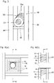
Figs. 6(a) and 6(b) is widely used. - In the structure for forming a penetration part in a fire prevention section forming member shown in
Figs. 6(a) and 6(b) , awooden frame 50 is assembled and fitted in advance to a wall or floor at a position at which a penetration part needs to be formed, and the inner circumference of thewooden frame 50 is covered with fireproof coveringmaterials 51 such as gypsum boards, and at the same time, fireproof coveringmaterials 52 such as gypsum boards are attached to the surface of the wall or floor around the penetration part. Then, atubular member 53 made of vinyl chloride, steel, or the like is passed through thewooden frame 50 preferably in a state of being supported by asupport member 54. A penetration part formed by thetubular member 53 is thereby formed. - Also, for example, in Japanese wooden buildings, a design where the wood surface of wooden beams and posts, which are constructional members, is exposed to the interior of a room, such as that of a traditional "shinkabe-zukuri" structure in which wooden beams and posts are exposed, is a popular design. The design in which the wood surface of wooden beams and posts is exposed to the interior of a room can be made to have desired fireproof by using a burning margin design. However, in the case where a penetration part is formed in a beam or post with a burning margin design as described above, fireproof may be lost at the penetration part, allowing fire to spread to the surroundings from the penetration part, and affecting the supporting force of a load supporting layer included in the beam or post with a burning margin design. For this reason, a fireproof wooden constructional member that prevents fire from spreading to the surroundings from a penetration part has been proposed (see, for example, Patent Literature 1).
- In the wooden constructional member disclosed in Patent Literature 1, a tubular member made of, for example, mortar acting as a firestop portion is passed through a penetration part extending through a beam so as to cover the inner circumferential surface of the penetration part, and a gap between the inner circumferential surface of the penetration part and the outer circumferential surface of the tubular member is filled with a filling material made of a fireproof material such as mortar. Patent Literature 1 also discloses that, other than mortar, gypsum, calcium silicate, or the like can be used as a large heat capacity material that can be used to form a firestop and can absorb heat.
- Patent Literature 1:
JP 6014320B JP 2017 075458 A JP 2016 065431 A US 5 174 077 A andUS 4 219 173 A . - However, in the conventional penetration part fireproof covering material that prevents fire from spreading to the surroundings from a penetration part, the tubular member provided in the penetration part is formed by casting, for example, a firestop material such as mortar, gypsum, or calcium silicate into a tubular mold, and then curing the firestop material. For this reason, sufficient dimensional accuracy cannot be obtained, and particularly when a penetration part that extends through a fireproof constructional member of a wooden building is covered for fireproof, it may be difficult to snugly fit the tubular member into the penetration part.
- In addition, a tubular molding mold that conforms to the shape of a penetration part needs to be formed each time, which increases the production cost.
- It is an object of the present invention to provide a penetration part fireproof covering material, wherein a fireproof covering material that is provided in a penetration part in a wooden building and functions as a firestop layer can be formed highly accurately and economically, and the penetration part can be covered for fireproof easily and at low cost.
- The present invention achieves the above-described object by providing a penetration part fireproof covering material used when a penetration part covered for fireproof is formed in a wooden building, wherein the fireproof covering material is formed to have a tubular shape by stacking a plurality of gypsum board pieces in a thickness direction and unitarily connecting the plurality of gypsum board pieces.
- In the penetration part fireproof covering material according to the present invention, it is preferable that the plurality of gypsum board pieces are annular gypsum board pieces.
- Also, in the penetration part fireproof covering material according to the present invention, it is preferable that the plurality of gypsum board pieces are cut out from gypsum boards of thicknesses of 9.5 mm to 25.5 mm.
- Furthermore, in the penetration part fireproof covering material according to the present invention, it is preferable that the plurality of gypsum board pieces are stacked and unitarily connected in such a manner that sheets of paper are attached to both sides of each gypsum board piece.
- Furthermore, in the penetration part fireproof covering material according to the present invention, it is preferable that the plurality of gypsum board pieces are stacked and unitarily connected to form the tubular shape by being fixed to each other using metal fasteners.
- Also, in the penetration part fireproof covering material according to the present invention, it is preferable that the plurality of gypsum board pieces are ring-shaped gypsum board pieces and are stacked and unitarily connected to form a cylindrical shape.
-
- [
Fig. 1] Fig. 1 is a schematic perspective view of a fireproof beam that is a fireproof constructional member and has a penetration part covered for fireproof by a penetration part fireproof covering material according to a preferred embodiment of the present invention. - [
Fig. 2] Fig. 2 is a cross sectional view taken along the line A-A shown inFig. 1 . - [
Fig. 3] Figs. 3(a) and 3(b) are schematic perspective views illustrating the step of forming a penetration part fireproof covering material. - [
Fig. 4] Figs. 4(a) to 4(d) are schematic perspective views illustrating exemplary embodiments of the penetration part fireproof covering material. - [
Fig. 5] Fig. 5 is a schematic perspective view showing an example of a state in which a penetration part covered for fireproof by a penetration part fireproof covering material is formed in a wall portion that is a fire prevention section forming member. - [
Fig. 6] Fig. 6 shows an example of a conventional structure for forming a penetration part in a fire prevention section forming member, withFig. 6(a) being a schematic cross sectional view taken along the line C-C shown inFig. 6(b), and Fig. 6(b) being a schematic cross sectional view taken along the line B-B shown inFig. 6(a) . - As shown in
Figs. 1 and 2 , a penetration part fireproof coveringmaterial 10 according to a preferred embodiment of the present invention is used, for example, when forming apenetration part 11 through which a pipe or a wire is to be passed in afireproof beam 20 that is a fireproof constructional member that constitutes a wooden building, to cover the inner circumferential surface of thepenetration part 11 to make it fireproof, so as to effectively avoid a situation in which the fireproof of thefireproof beam 20 is lost at thepenetration part 11, affecting the supporting force of a load supporting layer included in thefireproof beam 20. The penetration part fireproof coveringmaterial 10 according to the present embodiment can be formed easily, accurately, and economically by preferably using commercially available gypsum boards, and has a function of covering apenetration part 11 to make it fireproof easily and at low cost. - Also, the penetration part fireproof covering
material 10 according to the present embodiment is, for example, as shown inFigs. 1 and 2 , a fireproof covering material used when forming apenetration part 11 covered for fireproof in afireproof beam 20 that is a fireproof constructional member that constitutes a wooden building. As shown inFigs. 3(a) and 3(b) , the fireproof coveringmaterial 10 is formed to have a tubular shape by stacking a plurality ofgypsum board pieces 13a, which are preferably annular gypsum board pieces, in a thickness direction and unitarily connecting the plurality ofgypsum board pieces 13a. - Also, in the present embodiment, the plurality of annular
gypsum board pieces 13a are preferably ring-shaped gypsum board pieces that are cut out from commerciallyavailable gypsum boards 13 of thicknesses of 9.5 mm to 25.5 mm. The plurality of ring-shaped annulargypsum board pieces 13a are stacked and unitarily connected to form a cylindrical penetration part fireproof coveringmaterial 10 by being fixed to each other using metal fasteners, preferably, staples 14 (seeFig. 3(b) ). - In the present embodiment, as shown in
Figs. 1 and 2 , thefireproof beam 20 includes: astructural member 21 that serves as a load supporting layer; and a pair of coveringmembers 22 that are disposed on two side faces of thestructural member 21 to cover the side faces and function as burning margin layers or firestop layers. Thepenetration part 11 is opened preferably to perpendicularly or substantially perpendicularly intersect twoboundary portions 23 between thestructural member 21 and the coveringmembers 22. The penetration part fireproof coveringmaterial 10 in which the annulargypsum board pieces 13a are stacked is attached by being inserted through thepenetration part 11 such that a connectingportion 15 that connects annulargypsum board pieces 13a that are adjacent in the stacking direction is disposed at each of the twoboundary portions 23 between thestructural member 21 and the coveringmembers 22 of thefireproof beam 20, or at each portion close to theboundary portions 23. Here, the coveringmembers 22 function not only as burning margin layers, but also as firestop layers. Thestructural member 21 covered by the wooden coveringmembers 22 that function as burning margin layers can be deemed as astructural member 21 covered by the woodenfirestop covering members 22. - Also, in the present embodiment, the
fireproof beam 20 is preferably a fireproof beam that is designed to have a burning margin and has fireproof performance corresponding to a 45 minute quasi-fireproof structure or more. That is, thefireproof beam 20 includes: astructural member 21 that has, for example, an elongated rectangular cross sectional shape with a height of about 560 mm and a width of about 105 mm and functions as a structural beam material; a pair of coveringmembers 22 that are disposed to cover the side faces of thestructural beam material 21, have, for example, an elongated rectangular cross sectional shape with a height of about 560 mm and a width of about 105 mm as with thestructural member 21, and function as additional beam materials for a burning margin; and a fireproof coveringmaterial 24 that is attached to continuously cover the lower surface of thestructural member 21 and the lower surfaces of the coveringmembers 22 that are disposed on two sides. The fireproof coveringmaterial 24 has a function of protecting the wooden material covered by the fireproof coveringmaterial 24 from being burnt and damaged for 45 minutes or more in case of a fire and a function of protecting the same from being thermally degraded, and has a three-layer structure composed of, for example, gypsum boards or the like. Also, a decorativewooden board 25 is attached to cover the outer circumferential surface of the fireproof coveringmaterial 24, excluding the surface covering thestructural member 21 and the coveringmembers 22. - Here, the
structural member 21 and the pair of coveringmembers 22 that constitute thefireproof beam 20 may be unitarily connected using an adhesive, nails, screws, or the like. However, in the present embodiment, thestructural member 21 and the pair of coveringmembers 22 are preferably formed as a unitary body without being connected. Accordingly, in thestructural member 21 and the pair of coveringmembers 22, a height difference is likely to be generated at eachboundary portion 23 on the inner circumferential surface of thepenetration part 11 opened to intersect theboundary portion 23 due to differences in behavior caused when thestructural member 21 and the coveringmembers 22 dry and contract and when they support a load. In the present embodiment, the fireproof penetrationpart covering material 10 is formed by stacking and unitarily connecting a plurality of annulargypsum board pieces 13a fixed preferably usingstaples 14 as metal fasteners, and thus, as will be described later, the influence of height differences generated at theboundary portions 23 can be absorbed by the connectingportions 15. - In the present embodiment, the penetration part fireproof covering
material 10 that is attached by being inserted through thepenetration part 11 of thefireproof beam 20 is formed to have a cylindrical shape by stacking a plurality of ring-shaped annulargypsum board pieces 13a in the thickness direction, thegypsum board pieces 13a being preferably formed fromgypsum boards 13 of thicknesses of 9.5 mm to 25.5 mm as shown inFigs. 3(a) and 3(b) , and unitarily connecting the plurality of ring-shaped annulargypsum board pieces 13a. Thegypsum boards 13 are pieces of construction material obtained by wrapping a plate-shaped material composed mainly of gypsum with gypsum board base paper, and are known as pieces of material that have high thermal insulation and sound insulation. As thegypsum boards 13, any commercially available gypsum boards that are on the market as inexpensive plate-shaped members and are easily obtainable can be used. As thegypsum boards 13, "gypsum boards" "reinforced gypsum boards", "regular hard gypsum boards", or the like with thicknesses of 9.5 mm, 12.5 mm, 15 mm, 16mm, 18mm, 21mm, and 25 mm specified by JIS A 6901-2014 may be used. In the case where thegypsum boards 13 have the same thickness, it is preferable to use reinforced gypsum boards that are highly fireproof as thegypsum boards 13. According to JIS A 6901-2014, the tolerance of the thickness of a gypsum board is 0 mm to 0.5 mm. For example, for a 25 mm-thick gypsum board, a gypsum board having a thickness of 25 mm to 25.5 mm is allowed. Furthermore, agypsum board 13 can be accurately and easily cut out to have a desired shape using, for example, a known cutting tool such as a router. - In the present embodiment, the plurality of annular
gypsum board pieces 13a are formed by, for example, cutting commerciallyavailable gypsum boards 13 into, for example, a ring-shaped (doughnut shaped) planar shape with, for example, an inner diameter of about 115 mm and an outer diameter of about 195 mm, using a router. A cylindrical penetration part fireproof coveringmaterial 10 is formed by stacking a plurality of (in the present embodiment, twelve) cut-out ring-shaped annulargypsum board pieces 13a in the thickness direction and unitarily connecting them, preferably in such a manner that sheets of gypsum board base paper (not shown) are attached to two sides of eachgypsum board piece 13a. - Here, as a result of the annular
gypsum board pieces 13a being stacked in such a manner that sheets of gypsum board base paper (not shown) are attached to two sides of eachgypsum board piece 13a, the two sides of each annulargypsum board piece 13a are smooth, and the stacking surfaces of the annulargypsum board pieces 13a are smooth, and thus the annulargypsum board pieces 13a can be bonded without a gap. Also, as a result of the annulargypsum board pieces 13a being bonded without a gap using staples or the like, even when the annulargypsum board pieces 13a are stacked with the paper being attached thereto, the fireproof of a tubularfireproof covering material 12 can be ensured. The annulargypsum board pieces 13a may be stacked without the paper being attached to two sides of eachgypsum board piece 13a, and unitarily connected. - The plurality of annular
gypsum board pieces 13a can be stacked and unitarily connected using a known adhesive, but in the present embodiment, as described above, the plurality of annulargypsum board pieces 13a are stacked and unitarily connected preferably by being fixed to each other using staples 14 (seeFig. 3(b) ) as metal fasteners. The staples are wire members that are bent into a squared U shape and known as metal fasteners for fixing gypsum boards. By punching staples through a gypsum board using a tacker (staple gun) that is a tool known as a construction stapler, a gypsum board can be easily fixed to another gypsum board, a support member, and the like. If onestaple 14 is passed through, for example, two gypsum boards or more at a time, the gypsum boards may break. Accordingly, in the present embodiment, thestaples 14 have a leg length that is about 1.5 to 2 times longer than the thickness of a gypsum board, and are preferably sequentially punched through every two adjacent annulargypsum board pieces 13a of the stackedgypsum board pieces 13a so as to fix twelve annulargypsum board pieces 13a to each other and unitarily connect thegypsum board pieces 13a. Also, in the cylindrical penetration part fireproof coveringmaterial 10 formed by unitarily connecting twelve ring-shaped annulargypsum board pieces 13a, it is preferable to apply an adhesive such as, for example, an inorganic adhesive Tora Bond (registered trademark, available from Yoshino Gypsum Co., Ltd.) to the outer circumferential surface of the connectingportions 15 of adjacent annulargypsum board pieces 13a so as to increase connection strength and fireproof. - As the
metal fasteners 14 for fixing the plurality ofgypsum board pieces 13a to each other, in addition to thestaples 14, various types of known metal fittings can be used as metal fasteners such as nails, pins, and screws, for example. - In the present embodiment, the cylindrical penetration part fireproof covering
material 10 formed by unitarily connecting twelve ring-shaped annulargypsum board pieces 13a has, for example, a length of about 300 to 310 mm, which is slightly shorter than the length (315 mm) of thepenetration part 11 formed passing through thefireproof beam 20, and also has, for example, an outer diameter of 195 mm, which is slightly smaller than the inner diameter (200 mm) of thepenetration part 11. - Here, the penetration part fireproof covering
material 10 is formed by stacking a plurality of annulargypsum board pieces 13a that are cut out from commerciallyavailable gypsum boards 13 of thicknesses of, for example, 9.5 mm, 12.5 mm, 15 mm, 16mm, 18mm, 21mm, and 25 mm, and it is therefore possible to easily adjust the length of the fireproof penetrationpart covering material 10 to a desired length by selectinggypsum boards 13, from which annulargypsum board pieces 13a are cut out, among a plurality ofgypsum boards 13 having different thicknesses as appropriate, changing the combination of a plurality of cut-out annulargypsum board pieces 13a having different thicknesses, and stacking thegypsum board pieces 13a. Also, by selectinggypsum boards 13, from which annulargypsum board pieces 13a are cut out, among a plurality ofgypsum boards 13 having different thicknesses as appropriate, changing the combination of a plurality of cut-out annulargypsum board pieces 13a having different thicknesses, and stacking thegypsum board pieces 13a, the positions of the connectingportions 15 in the penetration part fireproof coveringmaterial 10 can be adjusted as appropriate such that, in a state in which the penetration part fireproof coveringmaterial 10 is inserted into thepenetration part 11 of thefireproof beam 20, two connectingportions 15 out of the connectingportions 15 of all of the adjacent annulargypsum board pieces 13a are disposed at twoboundary portions 23 between thestructural member 21 and the coveringmembers 22 of thefireproof beam 20, or at portions close to theboundary portions 23. - The annular
gypsum board pieces 13a that form the penetration part fireproof coveringmaterial 10 are not necessarily cut out to have a ring-shaped planar shape from commerciallyavailable gypsum boards 13 and stacked as shown inFig. 4(a) . As shown inFig. 4(b) , for example, a tubular penetration part fireproof coveringmaterial 10 in which a plurality of annulargypsum board pieces 13a obtained fromgypsum boards 13 are stacked in the thickness direction and unitarily connected (seeFig. 4(a) ) may be obtained by stackinggypsum board pieces 13a' that are cut out to have a halved ring shaped planar shape so as to form a divided fireproof covering material 12', and unitarily connecting a plurality of such divided fireproof covering materials 12' in the circumferential direction. As shown inFig. 4(c) , for example, the tubular penetration part fireproof coveringmaterial 10 in which a plurality of annulargypsum board pieces 13a obtained fromgypsum boards 13 are stacked in the thickness direction and unitarily connected (seeFig. 4(a) ) may also be obtained by stackinggypsum board pieces 13a" that are cut out to have a trisected ring shaped planar shape so as to form a dividedfireproof covering material 12", and unitarily connecting a plurality of such dividedfireproof covering materials 12" in the circumferential direction. - Alternatively, as shown in
Fig. 4(d) , for example, the tubular penetration part fireproof coveringmaterial 10 in which a plurality of annulargypsum board pieces 13a obtained fromgypsum boards 13 are stacked in the thickness direction and unitarily connected (seeFig. 4(a) ) may also be obtained by stacking a plurality ofgypsum board pieces 13a' that are cut out to have a halved ring shaped planar shape such that vertically adjacentgypsum board pieces 13a' are circumferentially staggered to form a plurality of divided fireproof covering materials 12', and unitarily connecting the divided fireproof covering materials 12' in the circumferential direction. - In the present embodiment, the penetration part fireproof covering
material 10 formed by unitarily connecting a plurality of annulargypsum board pieces 13a in the manner described above is attached by being inserted into thepenetration part 11 formed in thefireproof beam 20 so as to cover the inner circumferential surface of thepenetration part 11, and thepenetration part 11 is thereby covered for fireproof. That is, as shown inFigs. 1 and 2 , the penetration part fireproof coveringmaterial 10 formed in the manner described above is inserted into thepenetration part 11 formed to extend through thefireproof beam 20 and has a hollow circular cross section with an inner diameter of, for example, about 200 mm preferably such that the fourth and eighth connectingportions 15 out of eleven connectingportions 15 of adjacent annulargypsum board pieces 13a are disposed at twoboundary portions 23 between thestructural member 21 and the coveringmembers 22 of thefireproof beam 20, or at portions close to theboundary portions 23. Also, the penetration part fireproof coveringmaterial 10 is fixed to thepenetration part 11 by filling a gap between the outer circumferential surface of the inserted penetration part fireproof coveringmaterial 10 and the inner circumferential surface of thepenetration part 11 with, for example, a fireproof putty or the like and solidifying the putty. After that, the end faces are finished by preferably filling a gap at each end face of the penetration part fireproof coveringmaterial 10 fixed to thepenetration part 11 with a fireproof putty or the like. - In the present embodiment, a known floor member (not shown) that has predetermined fireproof performance is attached to the upper surface portion of the
fireproof beam 20 so as to cover the upper surface of thefireproof beam 20, and thus thestructural member 21 is not affected by heat from the upper surface side in case of a fire. Accordingly, even when a fireproof covering material is not provided on the upper surface portion of thefireproof beam 20, it is possible to effectively avoid a situation in which thestructural member 21 is burnt and damaged or thermally degraded. - Also, with the penetration part fireproof covering
material 10 according to the present embodiment configured as described above, it is possible to accurately and economically form a fireproof covering material that is installed in apenetration part 11 formed in a wooden building and functions as a firestop layer, and cover thepenetration part 11 for fireproof easily and at low cost. - That is, according to the present embodiment, the penetration part fireproof covering
material 10 is formed to have a tubular shape by stacking a plurality of annulargypsum board pieces 13a in the thickness direction and unitarily connecting thegypsum board pieces 13a. Accordingly, the penetration part fireproof coveringmaterial 10 can be formed accurately and economically by preferably accurately cutting a plurality of annulargypsum board pieces 13a from commercially availableinexpensive gypsum boards 13 with thicknesses of 9.5 mm to 25.5 mm, without making a tubular molding mold each time, and stacking the plurality of annulargypsum board pieces 13a. At the same time, thepenetration part 11 can be covered for fireproof easily and at low cost with a simple operation of installing the formed penetration part fireproof coveringmaterial 10 in thepenetration part 11 and fixing the formed penetration part fireproof coveringmaterial 10 to thepenetration part 11. - Also, in the present embodiment, the penetration part fireproof covering
material 10 is preferably formed by fixedly stacking a plurality of annulargypsum board pieces 13a and unitarily connecting thegypsum board pieces 13a, and attached to thepenetration part 11 such that two connectingportions 15 out of the connectingportions 15 that connect the annulargypsum board pieces 13a that are adjacent in the stacking direction are disposed at twoboundary portions 23 between thestructural member 21 and the coveringmembers 22 of thefireproof beam 20, or at portions close to theboundary portions 23. With this configuration, for example, even if height differences are generated at theboundary portions 23 in thepenetration part 11 due to differences in behavior caused when thestructural member 21 and the coveringmembers 22 dry and contract, and differences in behavior when they support a load, the generated height differences are absorbed because adjacent annulargypsum board pieces 13a are displaced on both sides of the connectingportions 15 provided at theboundary portions 23 or portions close to theboundary portions 23, and it is therefore possible to effectively avoid a situation in which the penetration part fireproof coveringmaterial 10 is likely to crack and the function as a firestop layer is likely to be lost. -
Fig. 5 shows an embodiment in which a penetration part fireproof coveringmaterial 30 that has the same configuration as described above is used when apenetration part 31 covered and made fireproof is formed in, for example, a fireproof wall that is a fire prevention section forming member for forming a fire prevention section in a wooden building. That is, in the embodiment shown inFig. 5 in which thepenetration part 31 is formed in the fireproof wall, the penetration part fireproof coveringmaterial 30 that preferably has a cylindrical shape and is formed by stacking, as gypsum board pieces, a plurality of ring-shaped annulargypsum board pieces 33a formed from gypsum boards preferably of thicknesses of 9.5 mm to 25.5 mm and unitarily connecting thegypsum board pieces 33a is placed on and fixed to a support table 35 that is attached by being supported by posts orstuds 34 that constitute the fireproof wall, and thepenetration part 31 of the penetration part fireproof coveringmaterial 30 is formed extending through the fireproof wall. Also, the penetration part fireproof coveringmaterial 30 covers the inner circumferential surface of thepenetration part 31, and the penetration part fireproof coveringmaterial 30 is attached to thepenetration part 31. - In the embodiment shown in
Fig. 5 in which thepenetration part 31 is formed in the fireproof wall, after the penetration part fireproof coveringmaterial 30 is attached, known wall surface materials having predetermined fireproof are attached to the front and back sides of the fireproof wall by being supported by the posts orstuds 34. In this way, a fireproof wall is formed in which thepenetration part 31 of the penetration part fireproof coveringmaterial 30 is provided. - Even in the embodiment shown in
Fig. 5 in which thepenetration part 31 is formed in the fireproof wall, the penetration part fireproof coveringmaterial 30 that forms thepenetration part 31 is formed to have a tubular shape by stacking a plurality of annulargypsum board pieces 33a formed from gypsum boards of thicknesses of 9.5 mm to 25.5 mm, in the thickness direction and unitarily connecting thegypsum board pieces 33a. Accordingly, advantageous effects that are the same those of the fireproof penetrationpart covering structure 10 of the above-described embodiment can be obtained. - The present invention is not limited to the embodiment described above, and various modifications can be made. For example, the gypsum board pieces are not necessarily ring-shaped annular gypsum board pieces, and may be annular gypsum board pieces of any other shape or gypsum board pieces that can be connected to form an annular shape. The penetration part fireproof covering material is not necessarily a cylindrical fireproof covering material, and may be a tubular fireproof covering material of any other shape such as a rectangular cylindrical shape. The fireproof constructional member in which a penetration part is formed is not necessarily a fireproof beam that includes a structural member that serves as a load supporting layer and a pair of covering members that serve as burning margin layers, and may be a fireproof beam that includes a structural member that serves as a load supporting layer and a burning margin layer or a firestop layer disposed to cover the surface of the structural member, or a covering member including a burning margin layer and a firestop layer disposed to cover the surface of the structural member, or may be any other fireproof constructional member that constitutes a wooden building such as a fireproof post.
- With the penetration part fireproof covering material according to the present invention, it is possible to accurately and economically form a fireproof covering material that is installed in a penetration part in a wooden building and functions as a firestop layer, and cover the penetration part for fireproof easily and at low cost.
Claims (6)
- A penetration part fireproof covering material used when a penetration part covered for fireproof is formed in a wooden building,
wherein the fireproof covering material is formed to have a tubular shape by stacking a plurality of gypsum board pieces in a thickness direction and unitarily connecting the plurality of gypsum board pieces. - The penetration part fireproof covering material according to claim 1,
wherein the plurality of gypsum board pieces are annular gypsum board pieces. - The penetration part fireproof covering material according to claim 1 or 2,
wherein the plurality of gypsum board pieces are cut out from gypsum boards of thicknesses of 9.5 mm to 25.5 mm. - The penetration part fireproof covering material according to claim 3,
wherein the plurality of gypsum board pieces are stacked and unitarily connected in such a manner that sheets of paper are attached to both sides of each gypsum board piece. - The penetration part fireproof covering material according to any one of claims 1 to 4,
wherein the plurality of gypsum board pieces are stacked and unitarily connected to form the tubular shape by being fixed to each other using metal fasteners. - The penetration part fireproof covering material according to any one of claims 1 to 5,
wherein the plurality of gypsum board pieces are ring-shaped gypsum board pieces and are stacked and unitarily connected to form a cylindrical shape.
Applications Claiming Priority (2)
| Application Number | Priority Date | Filing Date | Title |
|---|---|---|---|
| JP2017245527A JP6853775B2 (en) | 2017-12-21 | 2017-12-21 | Fireproof coating material for penetrations |
| PCT/JP2018/047033 WO2019124504A1 (en) | 2017-12-21 | 2018-12-20 | Penetration part fireproof coating material |
Publications (3)
| Publication Number | Publication Date |
|---|---|
| EP3730711A1 EP3730711A1 (en) | 2020-10-28 |
| EP3730711A4 EP3730711A4 (en) | 2021-10-06 |
| EP3730711B1 true EP3730711B1 (en) | 2022-06-15 |
Family
ID=66993525
Family Applications (1)
| Application Number | Title | Priority Date | Filing Date |
|---|---|---|---|
| EP18891390.9A Active EP3730711B1 (en) | 2017-12-21 | 2018-12-20 | Penetration part fireproof coating material |
Country Status (17)
| Country | Link |
|---|---|
| US (1) | US11624185B2 (en) |
| EP (1) | EP3730711B1 (en) |
| JP (1) | JP6853775B2 (en) |
| KR (1) | KR102685773B1 (en) |
| CN (1) | CN111433417B (en) |
| AU (1) | AU2018390267B2 (en) |
| DK (1) | DK3730711T3 (en) |
| ES (1) | ES2924505T3 (en) |
| MX (1) | MX2020005823A (en) |
| MY (1) | MY204561A (en) |
| PH (1) | PH12020500552A1 (en) |
| PL (1) | PL3730711T3 (en) |
| RU (1) | RU2765094C2 (en) |
| SA (1) | SA520412173B1 (en) |
| SG (1) | SG11202004769VA (en) |
| TW (1) | TWI762752B (en) |
| WO (1) | WO2019124504A1 (en) |
Families Citing this family (2)
| Publication number | Priority date | Publication date | Assignee | Title |
|---|---|---|---|---|
| CN112746689B (en) * | 2021-01-15 | 2022-10-11 | 淄博恒森耐火材料有限公司 | Refractory wall supporting device based on partition board separation |
| US11649628B2 (en) * | 2021-10-08 | 2023-05-16 | Eagle Materials Ip Llc | Area separation firewall system |
Family Cites Families (37)
| Publication number | Priority date | Publication date | Assignee | Title |
|---|---|---|---|---|
| FR2348329A1 (en) | 1976-04-14 | 1977-11-10 | Pont A Mousson | FIRE BARRIER FOR FUSE PIPE THROUGH A WALL |
| GB1597128A (en) * | 1977-10-05 | 1981-09-03 | Forbes G A | Insulated pipe supports |
| AT349708B (en) * | 1977-12-09 | 1979-04-25 | Isovolta | FIRE PROTECTION CLADDING FOR STEEL BEAM |
| JPS6014320B2 (en) | 1981-02-02 | 1985-04-12 | 日揮株式会社 | How to dispose of radioactive liquid waste |
| JPS6014320U (en) | 1983-07-09 | 1985-01-31 | 三住商事株式会社 | plain bearing |
| AU575796B2 (en) | 1983-12-02 | 1988-08-11 | Shikoku Kaken Kogyo Kabushiki Kaisha | Fireproofing columns or beams |
| US4736566A (en) * | 1984-01-17 | 1988-04-12 | Krotsch Harold V | Modular fabrication panel system |
| US5174077A (en) * | 1990-04-24 | 1992-12-29 | The Furukawa Electric Co., Ltd. | Fire protecting structure of channel portion of plastic piping in a fire partition |
| CN1063736A (en) * | 1990-10-11 | 1992-08-19 | 纤维胶接技术Pty有限公司 | Fire-resistant load-bearing building structure |
| JPH07127766A (en) | 1993-11-05 | 1995-05-16 | Misawa Homes Co Ltd | Fire-resistant structure of boundary floor |
| DE69722822T2 (en) | 1997-01-16 | 2004-05-06 | Sekisui Chemical Co., Ltd. | FIRE RESISTANT SHEET SHAPED MOLDING, FIRE RESISTANT LAMINATE FOR COVERING STEEL, FIRE RESISTANT STRUCTURE FOR A WALL AND METHOD FOR BUILDING FIRE RESISTANT STEEL AND FIRE RESISTANT WALL |
| AUPQ024099A0 (en) | 1999-05-07 | 1999-06-03 | Promat Fyreguard Pty Ltd | Service shut off device |
| DE10039720A1 (en) | 2000-08-14 | 2002-02-28 | Hilti Ag | Fire protection sleeve |
| NL1018722C2 (en) | 2001-08-07 | 2003-02-10 | Beele Eng Bv | Fire-resistant system and method for passing at least one cable, tube or the like through an opening of a wall. |
| JP4041904B2 (en) * | 2002-07-15 | 2008-02-06 | 新日本製鐵株式会社 | Pipe member for heating furnace |
| JP3817532B2 (en) | 2003-01-10 | 2006-09-06 | 積水化学工業株式会社 | Fireproof compartment penetration structure |
| JP4533006B2 (en) * | 2004-06-08 | 2010-08-25 | 積水化学工業株式会社 | Fire-proof compartment penetration structure and construction method of fire-proof compartment penetration |
| GB0712271D0 (en) | 2007-06-22 | 2007-08-01 | Beele Eng Bv | Method and sealing system for sealing an annular space between a rigid conduit and a pipe, tube or duct extending through the conduit |
| JP5427782B2 (en) | 2008-12-11 | 2014-02-26 | 積水化学工業株式会社 | Fire prevention compartment penetration structure and construction method thereof |
| CN201391684Y (en) | 2009-01-19 | 2010-01-27 | 李泉涌 | Composite fire-resisting sleeve |
| DE102009060411B4 (en) | 2009-12-22 | 2012-09-06 | Svt Brandschutz Vertriebsgesellschaft Mbh International | Fire-protected cable feedthrough |
| WO2012077229A1 (en) * | 2010-12-10 | 2012-06-14 | 吉野石膏株式会社 | Dried gypsum composition and gypsum-based coating material |
| CN202483024U (en) * | 2012-03-16 | 2012-10-10 | 宝钢建筑系统集成有限公司 | Square steel tube column fireproofing structure |
| US8668247B2 (en) | 2012-04-23 | 2014-03-11 | GM Global Technology Operations LLC | Magnesium-composite structures with enhanced design |
| CN104153475B (en) | 2014-07-22 | 2016-08-17 | 开县人人有余科技有限公司 | The preparation method of insulated fire architectural shape |
| JP6482224B2 (en) * | 2014-09-26 | 2019-03-13 | 株式会社竹中工務店 | Structural member |
| JP6433358B2 (en) * | 2015-03-27 | 2018-12-05 | 株式会社フジタ | Fire door |
| CN204828966U (en) | 2015-06-24 | 2015-12-02 | 中国建筑第八工程局有限公司 | Electric wire tube wears fire resistive construction of light steel joist gypsum -lath partition wall |
| CN204828967U (en) | 2015-06-24 | 2015-12-02 | 中国建筑第八工程局有限公司 | Circular hot oil line wears fire resistive construction of light steel joist gypsum -lath partition wall |
| JP6719188B2 (en) * | 2015-10-13 | 2020-07-08 | 株式会社竹中工務店 | Structural member |
| CN205134742U (en) | 2015-12-01 | 2016-04-06 | 山东科技大学 | Multilayer fire -proof material's novel steel reinforced concrete fire prevention post |
| JP2017122322A (en) * | 2016-01-06 | 2017-07-13 | 大成建設株式会社 | Fireproof structure |
| CN105863092B (en) | 2016-04-05 | 2018-05-18 | 上海十三冶建设有限公司 | A kind of installation method of smoke control system fire-proof plate |
| DE102016108538A1 (en) * | 2016-05-09 | 2017-11-09 | Tremco Illbruck Produktion Gmbh | Fire protection tape |
| CN206599936U (en) * | 2017-02-21 | 2017-10-31 | 泰山石膏(江阴)有限公司 | One kind fire prevention Thistle board |
| CN107476447A (en) | 2017-09-29 | 2017-12-15 | 江苏天时新材料科技有限公司 | A kind of corrosion-resistant plate structure |
| RU2705620C1 (en) | 2018-12-24 | 2019-11-11 | Василий Алексеевич Прусаков | Fire-resistant cable tunneling for walls and floors of buildings |
-
2017
- 2017-12-21 JP JP2017245527A patent/JP6853775B2/en active Active
-
2018
- 2018-12-20 PL PL18891390.9T patent/PL3730711T3/en unknown
- 2018-12-20 DK DK18891390.9T patent/DK3730711T3/en active
- 2018-12-20 ES ES18891390T patent/ES2924505T3/en active Active
- 2018-12-20 SG SG11202004769VA patent/SG11202004769VA/en unknown
- 2018-12-20 MX MX2020005823A patent/MX2020005823A/en unknown
- 2018-12-20 CN CN201880078240.XA patent/CN111433417B/en active Active
- 2018-12-20 RU RU2020121395A patent/RU2765094C2/en active
- 2018-12-20 EP EP18891390.9A patent/EP3730711B1/en active Active
- 2018-12-20 KR KR1020207016793A patent/KR102685773B1/en active Active
- 2018-12-20 MY MYPI2020002980A patent/MY204561A/en unknown
- 2018-12-20 AU AU2018390267A patent/AU2018390267B2/en active Active
- 2018-12-20 WO PCT/JP2018/047033 patent/WO2019124504A1/en not_active Ceased
- 2018-12-20 US US16/771,507 patent/US11624185B2/en active Active
- 2018-12-21 TW TW107146473A patent/TWI762752B/en active
-
2020
- 2020-06-11 SA SA520412173A patent/SA520412173B1/en unknown
- 2020-06-11 PH PH12020500552A patent/PH12020500552A1/en unknown
Also Published As
| Publication number | Publication date |
|---|---|
| RU2020121395A (en) | 2022-01-21 |
| AU2018390267B2 (en) | 2024-02-15 |
| BR112020011532A2 (en) | 2020-11-17 |
| MX2020005823A (en) | 2020-08-20 |
| SA520412173B1 (en) | 2022-07-19 |
| KR20200099527A (en) | 2020-08-24 |
| CN111433417A (en) | 2020-07-17 |
| US11624185B2 (en) | 2023-04-11 |
| PL3730711T3 (en) | 2022-09-05 |
| AU2018390267A1 (en) | 2020-06-25 |
| MY204561A (en) | 2024-09-04 |
| PH12020500552A1 (en) | 2021-05-31 |
| RU2020121395A3 (en) | 2022-01-21 |
| RU2765094C2 (en) | 2022-01-25 |
| SG11202004769VA (en) | 2020-07-29 |
| KR102685773B1 (en) | 2024-07-18 |
| DK3730711T3 (en) | 2022-06-27 |
| JP2019112794A (en) | 2019-07-11 |
| EP3730711A4 (en) | 2021-10-06 |
| CN111433417B (en) | 2021-11-09 |
| ES2924505T3 (en) | 2022-10-07 |
| US20200299956A1 (en) | 2020-09-24 |
| WO2019124504A1 (en) | 2019-06-27 |
| TW201938889A (en) | 2019-10-01 |
| JP6853775B2 (en) | 2021-03-31 |
| TWI762752B (en) | 2022-05-01 |
| CA3085430A1 (en) | 2019-06-27 |
| EP3730711A1 (en) | 2020-10-28 |
Similar Documents
| Publication | Publication Date | Title |
|---|---|---|
| CA2827183C (en) | Fire-rated wall construction product | |
| US11624185B2 (en) | Penetration part fireproof coating material | |
| EP3730712B9 (en) | Fireproof coated structure for penetration part | |
| CA3085430C (en) | Penetration part fireproof coating material | |
| CA3085413C (en) | Fireproof coated structure for penetration part | |
| JP2013147840A (en) | Fireproof treatment structure of penetration part of piping/wiring | |
| JP2013072266A (en) | Building panel | |
| BR112020011532B1 (en) | PENETRATION PART FIREPROOF COATING MATERIAL | |
| HK40027228B (en) | Penetration part fireproof coating material | |
| HK40027228A (en) | Penetration part fireproof coating material | |
| BR112020011530B1 (en) | FIREPROOF COVERED STRUCTURE FOR PENETRATION PART | |
| HK40027229B (en) | Fireproof coated structure for penetration part | |
| HK40027229A (en) | Fireproof coated structure for penetration part | |
| JP6502089B2 (en) | Thermal insulation wall and construction method of thermal insulation wall |
Legal Events
| Date | Code | Title | Description |
|---|---|---|---|
| STAA | Information on the status of an ep patent application or granted ep patent |
Free format text: STATUS: THE INTERNATIONAL PUBLICATION HAS BEEN MADE |
|
| PUAI | Public reference made under article 153(3) epc to a published international application that has entered the european phase |
Free format text: ORIGINAL CODE: 0009012 |
|
| STAA | Information on the status of an ep patent application or granted ep patent |
Free format text: STATUS: REQUEST FOR EXAMINATION WAS MADE |
|
| 17P | Request for examination filed |
Effective date: 20200622 |
|
| AK | Designated contracting states |
Kind code of ref document: A1 Designated state(s): AL AT BE BG CH CY CZ DE DK EE ES FI FR GB GR HR HU IE IS IT LI LT LU LV MC MK MT NL NO PL PT RO RS SE SI SK SM TR |
|
| AX | Request for extension of the european patent |
Extension state: BA ME |
|
| DAV | Request for validation of the european patent (deleted) | ||
| DAX | Request for extension of the european patent (deleted) | ||
| A4 | Supplementary search report drawn up and despatched |
Effective date: 20210908 |
|
| RIC1 | Information provided on ipc code assigned before grant |
Ipc: B32B 29/00 20060101ALI20210901BHEP Ipc: B32B 13/08 20060101ALI20210901BHEP Ipc: B32B 13/04 20060101ALI20210901BHEP Ipc: B32B 7/08 20190101ALI20210901BHEP Ipc: B32B 3/18 20060101ALI20210901BHEP Ipc: B32B 1/08 20060101ALI20210901BHEP Ipc: F16L 5/04 20060101ALI20210901BHEP Ipc: E04B 1/94 20060101AFI20210901BHEP |
|
| GRAP | Despatch of communication of intention to grant a patent |
Free format text: ORIGINAL CODE: EPIDOSNIGR1 |
|
| STAA | Information on the status of an ep patent application or granted ep patent |
Free format text: STATUS: GRANT OF PATENT IS INTENDED |
|
| INTG | Intention to grant announced |
Effective date: 20220211 |
|
| GRAS | Grant fee paid |
Free format text: ORIGINAL CODE: EPIDOSNIGR3 |
|
| GRAA | (expected) grant |
Free format text: ORIGINAL CODE: 0009210 |
|
| STAA | Information on the status of an ep patent application or granted ep patent |
Free format text: STATUS: THE PATENT HAS BEEN GRANTED |
|
| AK | Designated contracting states |
Kind code of ref document: B1 Designated state(s): AL AT BE BG CH CY CZ DE DK EE ES FI FR GB GR HR HU IE IS IT LI LT LU LV MC MK MT NL NO PL PT RO RS SE SI SK SM TR |
|
| REG | Reference to a national code |
Ref country code: CH Ref legal event code: EP Ref country code: GB Ref legal event code: FG4D |
|
| REG | Reference to a national code |
Ref country code: FI Ref legal event code: FGE |
|
| REG | Reference to a national code |
Ref country code: DK Ref legal event code: T3 Effective date: 20220622 |
|
| REG | Reference to a national code |
Ref country code: IE Ref legal event code: FG4D |
|
| REG | Reference to a national code |
Ref country code: DE Ref legal event code: R096 Ref document number: 602018036889 Country of ref document: DE |
|
| REG | Reference to a national code |
Ref country code: SE Ref legal event code: TRGR |
|
| REG | Reference to a national code |
Ref country code: AT Ref legal event code: REF Ref document number: 1498493 Country of ref document: AT Kind code of ref document: T Effective date: 20220715 |
|
| REG | Reference to a national code |
Ref country code: NL Ref legal event code: FP |
|
| REG | Reference to a national code |
Ref country code: NO Ref legal event code: T2 Effective date: 20220615 |
|
| REG | Reference to a national code |
Ref country code: ES Ref legal event code: FG2A Ref document number: 2924505 Country of ref document: ES Kind code of ref document: T3 Effective date: 20221007 |
|
| REG | Reference to a national code |
Ref country code: LT Ref legal event code: MG9D |
|
| REG | Reference to a national code |
Ref country code: GR Ref legal event code: EP Ref document number: 20220401563 Country of ref document: GR Effective date: 20221010 |
|
| PG25 | Lapsed in a contracting state [announced via postgrant information from national office to epo] |
Ref country code: LT Free format text: LAPSE BECAUSE OF FAILURE TO SUBMIT A TRANSLATION OF THE DESCRIPTION OR TO PAY THE FEE WITHIN THE PRESCRIBED TIME-LIMIT Effective date: 20220615 Ref country code: HR Free format text: LAPSE BECAUSE OF FAILURE TO SUBMIT A TRANSLATION OF THE DESCRIPTION OR TO PAY THE FEE WITHIN THE PRESCRIBED TIME-LIMIT Effective date: 20220615 Ref country code: BG Free format text: LAPSE BECAUSE OF FAILURE TO SUBMIT A TRANSLATION OF THE DESCRIPTION OR TO PAY THE FEE WITHIN THE PRESCRIBED TIME-LIMIT Effective date: 20220915 |
|
| PG25 | Lapsed in a contracting state [announced via postgrant information from national office to epo] |
Ref country code: RS Free format text: LAPSE BECAUSE OF FAILURE TO SUBMIT A TRANSLATION OF THE DESCRIPTION OR TO PAY THE FEE WITHIN THE PRESCRIBED TIME-LIMIT Effective date: 20220615 Ref country code: LV Free format text: LAPSE BECAUSE OF FAILURE TO SUBMIT A TRANSLATION OF THE DESCRIPTION OR TO PAY THE FEE WITHIN THE PRESCRIBED TIME-LIMIT Effective date: 20220615 |
|
| PG25 | Lapsed in a contracting state [announced via postgrant information from national office to epo] |
Ref country code: SM Free format text: LAPSE BECAUSE OF FAILURE TO SUBMIT A TRANSLATION OF THE DESCRIPTION OR TO PAY THE FEE WITHIN THE PRESCRIBED TIME-LIMIT Effective date: 20220615 Ref country code: SK Free format text: LAPSE BECAUSE OF FAILURE TO SUBMIT A TRANSLATION OF THE DESCRIPTION OR TO PAY THE FEE WITHIN THE PRESCRIBED TIME-LIMIT Effective date: 20220615 Ref country code: RO Free format text: LAPSE BECAUSE OF FAILURE TO SUBMIT A TRANSLATION OF THE DESCRIPTION OR TO PAY THE FEE WITHIN THE PRESCRIBED TIME-LIMIT Effective date: 20220615 Ref country code: PT Free format text: LAPSE BECAUSE OF FAILURE TO SUBMIT A TRANSLATION OF THE DESCRIPTION OR TO PAY THE FEE WITHIN THE PRESCRIBED TIME-LIMIT Effective date: 20221017 Ref country code: EE Free format text: LAPSE BECAUSE OF FAILURE TO SUBMIT A TRANSLATION OF THE DESCRIPTION OR TO PAY THE FEE WITHIN THE PRESCRIBED TIME-LIMIT Effective date: 20220615 |
|
| PG25 | Lapsed in a contracting state [announced via postgrant information from national office to epo] |
Ref country code: IS Free format text: LAPSE BECAUSE OF FAILURE TO SUBMIT A TRANSLATION OF THE DESCRIPTION OR TO PAY THE FEE WITHIN THE PRESCRIBED TIME-LIMIT Effective date: 20221015 |
|
| REG | Reference to a national code |
Ref country code: DE Ref legal event code: R097 Ref document number: 602018036889 Country of ref document: DE |
|
| PG25 | Lapsed in a contracting state [announced via postgrant information from national office to epo] |
Ref country code: AL Free format text: LAPSE BECAUSE OF FAILURE TO SUBMIT A TRANSLATION OF THE DESCRIPTION OR TO PAY THE FEE WITHIN THE PRESCRIBED TIME-LIMIT Effective date: 20220615 |
|
| PLBE | No opposition filed within time limit |
Free format text: ORIGINAL CODE: 0009261 |
|
| STAA | Information on the status of an ep patent application or granted ep patent |
Free format text: STATUS: NO OPPOSITION FILED WITHIN TIME LIMIT |
|
| 26N | No opposition filed |
Effective date: 20230316 |
|
| PG25 | Lapsed in a contracting state [announced via postgrant information from national office to epo] |
Ref country code: SI Free format text: LAPSE BECAUSE OF FAILURE TO SUBMIT A TRANSLATION OF THE DESCRIPTION OR TO PAY THE FEE WITHIN THE PRESCRIBED TIME-LIMIT Effective date: 20220615 |
|
| P01 | Opt-out of the competence of the unified patent court (upc) registered |
Effective date: 20230522 |
|
| REG | Reference to a national code |
Ref country code: CH Ref legal event code: PL |
|
| REG | Reference to a national code |
Ref country code: AT Ref legal event code: UEP Ref document number: 1498493 Country of ref document: AT Kind code of ref document: T Effective date: 20220615 |
|
| PG25 | Lapsed in a contracting state [announced via postgrant information from national office to epo] |
Ref country code: LU Free format text: LAPSE BECAUSE OF NON-PAYMENT OF DUE FEES Effective date: 20221220 |
|
| PG25 | Lapsed in a contracting state [announced via postgrant information from national office to epo] |
Ref country code: LI Free format text: LAPSE BECAUSE OF NON-PAYMENT OF DUE FEES Effective date: 20221231 Ref country code: IE Free format text: LAPSE BECAUSE OF NON-PAYMENT OF DUE FEES Effective date: 20221220 Ref country code: CH Free format text: LAPSE BECAUSE OF NON-PAYMENT OF DUE FEES Effective date: 20221231 |
|
| PG25 | Lapsed in a contracting state [announced via postgrant information from national office to epo] |
Ref country code: CY Free format text: LAPSE BECAUSE OF FAILURE TO SUBMIT A TRANSLATION OF THE DESCRIPTION OR TO PAY THE FEE WITHIN THE PRESCRIBED TIME-LIMIT Effective date: 20220615 |
|
| PG25 | Lapsed in a contracting state [announced via postgrant information from national office to epo] |
Ref country code: MK Free format text: LAPSE BECAUSE OF FAILURE TO SUBMIT A TRANSLATION OF THE DESCRIPTION OR TO PAY THE FEE WITHIN THE PRESCRIBED TIME-LIMIT Effective date: 20220615 Ref country code: HU Free format text: LAPSE BECAUSE OF FAILURE TO SUBMIT A TRANSLATION OF THE DESCRIPTION OR TO PAY THE FEE WITHIN THE PRESCRIBED TIME-LIMIT; INVALID AB INITIO Effective date: 20181220 |
|
| PG25 | Lapsed in a contracting state [announced via postgrant information from national office to epo] |
Ref country code: MC Free format text: LAPSE BECAUSE OF FAILURE TO SUBMIT A TRANSLATION OF THE DESCRIPTION OR TO PAY THE FEE WITHIN THE PRESCRIBED TIME-LIMIT Effective date: 20220615 |
|
| PG25 | Lapsed in a contracting state [announced via postgrant information from national office to epo] |
Ref country code: MC Free format text: LAPSE BECAUSE OF FAILURE TO SUBMIT A TRANSLATION OF THE DESCRIPTION OR TO PAY THE FEE WITHIN THE PRESCRIBED TIME-LIMIT Effective date: 20220615 |
|
| PG25 | Lapsed in a contracting state [announced via postgrant information from national office to epo] |
Ref country code: MT Free format text: LAPSE BECAUSE OF FAILURE TO SUBMIT A TRANSLATION OF THE DESCRIPTION OR TO PAY THE FEE WITHIN THE PRESCRIBED TIME-LIMIT Effective date: 20220615 |
|
| PG25 | Lapsed in a contracting state [announced via postgrant information from national office to epo] |
Ref country code: BG Free format text: LAPSE BECAUSE OF FAILURE TO SUBMIT A TRANSLATION OF THE DESCRIPTION OR TO PAY THE FEE WITHIN THE PRESCRIBED TIME-LIMIT Effective date: 20220615 |
|
| PG25 | Lapsed in a contracting state [announced via postgrant information from national office to epo] |
Ref country code: BG Free format text: LAPSE BECAUSE OF FAILURE TO SUBMIT A TRANSLATION OF THE DESCRIPTION OR TO PAY THE FEE WITHIN THE PRESCRIBED TIME-LIMIT Effective date: 20220615 |
|
| PGFP | Annual fee paid to national office [announced via postgrant information from national office to epo] |
Ref country code: DK Payment date: 20241217 Year of fee payment: 7 |
|
| PGFP | Annual fee paid to national office [announced via postgrant information from national office to epo] |
Ref country code: PL Payment date: 20241209 Year of fee payment: 7 Ref country code: FI Payment date: 20241216 Year of fee payment: 7 Ref country code: GR Payment date: 20241213 Year of fee payment: 7 |
|
| PGFP | Annual fee paid to national office [announced via postgrant information from national office to epo] |
Ref country code: CZ Payment date: 20241206 Year of fee payment: 7 |
|
| PGFP | Annual fee paid to national office [announced via postgrant information from national office to epo] |
Ref country code: ES Payment date: 20250117 Year of fee payment: 7 |
|
| PGFP | Annual fee paid to national office [announced via postgrant information from national office to epo] |
Ref country code: TR Payment date: 20241211 Year of fee payment: 7 |
|
| PGFP | Annual fee paid to national office [announced via postgrant information from national office to epo] |
Ref country code: GB Payment date: 20251218 Year of fee payment: 8 |
|
| PGFP | Annual fee paid to national office [announced via postgrant information from national office to epo] |
Ref country code: NO Payment date: 20251216 Year of fee payment: 8 |
|
| PGFP | Annual fee paid to national office [announced via postgrant information from national office to epo] |
Ref country code: AT Payment date: 20251215 Year of fee payment: 8 |
|
| PGFP | Annual fee paid to national office [announced via postgrant information from national office to epo] |
Ref country code: NL Payment date: 20251217 Year of fee payment: 8 Ref country code: FR Payment date: 20251218 Year of fee payment: 8 |
|
| PGFP | Annual fee paid to national office [announced via postgrant information from national office to epo] |
Ref country code: BE Payment date: 20251218 Year of fee payment: 8 |
|
| PGFP | Annual fee paid to national office [announced via postgrant information from national office to epo] |
Ref country code: SE Payment date: 20251217 Year of fee payment: 8 |
|
| PGFP | Annual fee paid to national office [announced via postgrant information from national office to epo] |
Ref country code: DE Payment date: 20251218 Year of fee payment: 8 |
|
| PGFP | Annual fee paid to national office [announced via postgrant information from national office to epo] |
Ref country code: IT Payment date: 20251231 Year of fee payment: 8 |