EP3730328B1 - Vehicle comprising a battery device - Google Patents
Vehicle comprising a battery device Download PDFInfo
- Publication number
- EP3730328B1 EP3730328B1 EP20158389.5A EP20158389A EP3730328B1 EP 3730328 B1 EP3730328 B1 EP 3730328B1 EP 20158389 A EP20158389 A EP 20158389A EP 3730328 B1 EP3730328 B1 EP 3730328B1
- Authority
- EP
- European Patent Office
- Prior art keywords
- vehicle
- battery
- battery modules
- disposed
- relay device
- Prior art date
- Legal status (The legal status is an assumption and is not a legal conclusion. Google has not performed a legal analysis and makes no representation as to the accuracy of the status listed.)
- Active
Links
Images


Classifications
-
- B—PERFORMING OPERATIONS; TRANSPORTING
- B60—VEHICLES IN GENERAL
- B60K—ARRANGEMENT OR MOUNTING OF PROPULSION UNITS OR OF TRANSMISSIONS IN VEHICLES; ARRANGEMENT OR MOUNTING OF PLURAL DIVERSE PRIME-MOVERS IN VEHICLES; AUXILIARY DRIVES FOR VEHICLES; INSTRUMENTATION OR DASHBOARDS FOR VEHICLES; ARRANGEMENTS IN CONNECTION WITH COOLING, AIR INTAKE, GAS EXHAUST OR FUEL SUPPLY OF PROPULSION UNITS IN VEHICLES
- B60K1/00—Arrangement or mounting of electrical propulsion units
- B60K1/04—Arrangement or mounting of electrical propulsion units of the electric storage means for propulsion
-
- B—PERFORMING OPERATIONS; TRANSPORTING
- B60—VEHICLES IN GENERAL
- B60L—PROPULSION OF ELECTRICALLY-PROPELLED VEHICLES; SUPPLYING ELECTRIC POWER FOR AUXILIARY EQUIPMENT OF ELECTRICALLY-PROPELLED VEHICLES; ELECTRODYNAMIC BRAKE SYSTEMS FOR VEHICLES IN GENERAL; MAGNETIC SUSPENSION OR LEVITATION FOR VEHICLES; MONITORING OPERATING VARIABLES OF ELECTRICALLY-PROPELLED VEHICLES; ELECTRIC SAFETY DEVICES FOR ELECTRICALLY-PROPELLED VEHICLES
- B60L50/00—Electric propulsion with power supplied within the vehicle
- B60L50/50—Electric propulsion with power supplied within the vehicle using propulsion power supplied by batteries or fuel cells
- B60L50/60—Electric propulsion with power supplied within the vehicle using propulsion power supplied by batteries or fuel cells using power supplied by batteries
- B60L50/64—Constructional details of batteries specially adapted for electric vehicles
-
- B—PERFORMING OPERATIONS; TRANSPORTING
- B60—VEHICLES IN GENERAL
- B60L—PROPULSION OF ELECTRICALLY-PROPELLED VEHICLES; SUPPLYING ELECTRIC POWER FOR AUXILIARY EQUIPMENT OF ELECTRICALLY-PROPELLED VEHICLES; ELECTRODYNAMIC BRAKE SYSTEMS FOR VEHICLES IN GENERAL; MAGNETIC SUSPENSION OR LEVITATION FOR VEHICLES; MONITORING OPERATING VARIABLES OF ELECTRICALLY-PROPELLED VEHICLES; ELECTRIC SAFETY DEVICES FOR ELECTRICALLY-PROPELLED VEHICLES
- B60L50/00—Electric propulsion with power supplied within the vehicle
- B60L50/50—Electric propulsion with power supplied within the vehicle using propulsion power supplied by batteries or fuel cells
- B60L50/60—Electric propulsion with power supplied within the vehicle using propulsion power supplied by batteries or fuel cells using power supplied by batteries
- B60L50/66—Arrangements of batteries
-
- H—ELECTRICITY
- H01—ELECTRIC ELEMENTS
- H01M—PROCESSES OR MEANS, e.g. BATTERIES, FOR THE DIRECT CONVERSION OF CHEMICAL ENERGY INTO ELECTRICAL ENERGY
- H01M10/00—Secondary cells; Manufacture thereof
- H01M10/42—Methods or arrangements for servicing or maintenance of secondary cells or secondary half-cells
- H01M10/425—Structural combination with electronic components, e.g. electronic circuits integrated to the outside of the casing
-
- H—ELECTRICITY
- H01—ELECTRIC ELEMENTS
- H01M—PROCESSES OR MEANS, e.g. BATTERIES, FOR THE DIRECT CONVERSION OF CHEMICAL ENERGY INTO ELECTRICAL ENERGY
- H01M10/00—Secondary cells; Manufacture thereof
- H01M10/42—Methods or arrangements for servicing or maintenance of secondary cells or secondary half-cells
- H01M10/44—Methods for charging or discharging
-
- H—ELECTRICITY
- H01—ELECTRIC ELEMENTS
- H01M—PROCESSES OR MEANS, e.g. BATTERIES, FOR THE DIRECT CONVERSION OF CHEMICAL ENERGY INTO ELECTRICAL ENERGY
- H01M50/00—Constructional details or processes of manufacture of the non-active parts of electrochemical cells other than fuel cells, e.g. hybrid cells
- H01M50/20—Mountings; Secondary casings or frames; Racks, modules or packs; Suspension devices; Shock absorbers; Transport or carrying devices; Holders
- H01M50/204—Racks, modules or packs for multiple batteries or multiple cells
-
- H—ELECTRICITY
- H01—ELECTRIC ELEMENTS
- H01M—PROCESSES OR MEANS, e.g. BATTERIES, FOR THE DIRECT CONVERSION OF CHEMICAL ENERGY INTO ELECTRICAL ENERGY
- H01M50/00—Constructional details or processes of manufacture of the non-active parts of electrochemical cells other than fuel cells, e.g. hybrid cells
- H01M50/20—Mountings; Secondary casings or frames; Racks, modules or packs; Suspension devices; Shock absorbers; Transport or carrying devices; Holders
- H01M50/249—Mountings; Secondary casings or frames; Racks, modules or packs; Suspension devices; Shock absorbers; Transport or carrying devices; Holders specially adapted for aircraft or vehicles, e.g. cars or trains
-
- B—PERFORMING OPERATIONS; TRANSPORTING
- B60—VEHICLES IN GENERAL
- B60K—ARRANGEMENT OR MOUNTING OF PROPULSION UNITS OR OF TRANSMISSIONS IN VEHICLES; ARRANGEMENT OR MOUNTING OF PLURAL DIVERSE PRIME-MOVERS IN VEHICLES; AUXILIARY DRIVES FOR VEHICLES; INSTRUMENTATION OR DASHBOARDS FOR VEHICLES; ARRANGEMENTS IN CONNECTION WITH COOLING, AIR INTAKE, GAS EXHAUST OR FUEL SUPPLY OF PROPULSION UNITS IN VEHICLES
- B60K1/00—Arrangement or mounting of electrical propulsion units
- B60K1/04—Arrangement or mounting of electrical propulsion units of the electric storage means for propulsion
- B60K2001/0405—Arrangement or mounting of electrical propulsion units of the electric storage means for propulsion characterised by their position
- B60K2001/0422—Arrangement under the front seats
-
- B—PERFORMING OPERATIONS; TRANSPORTING
- B60—VEHICLES IN GENERAL
- B60K—ARRANGEMENT OR MOUNTING OF PROPULSION UNITS OR OF TRANSMISSIONS IN VEHICLES; ARRANGEMENT OR MOUNTING OF PLURAL DIVERSE PRIME-MOVERS IN VEHICLES; AUXILIARY DRIVES FOR VEHICLES; INSTRUMENTATION OR DASHBOARDS FOR VEHICLES; ARRANGEMENTS IN CONNECTION WITH COOLING, AIR INTAKE, GAS EXHAUST OR FUEL SUPPLY OF PROPULSION UNITS IN VEHICLES
- B60K1/00—Arrangement or mounting of electrical propulsion units
- B60K1/04—Arrangement or mounting of electrical propulsion units of the electric storage means for propulsion
- B60K2001/0405—Arrangement or mounting of electrical propulsion units of the electric storage means for propulsion characterised by their position
- B60K2001/0433—Arrangement under the rear seats
-
- B—PERFORMING OPERATIONS; TRANSPORTING
- B60—VEHICLES IN GENERAL
- B60K—ARRANGEMENT OR MOUNTING OF PROPULSION UNITS OR OF TRANSMISSIONS IN VEHICLES; ARRANGEMENT OR MOUNTING OF PLURAL DIVERSE PRIME-MOVERS IN VEHICLES; AUXILIARY DRIVES FOR VEHICLES; INSTRUMENTATION OR DASHBOARDS FOR VEHICLES; ARRANGEMENTS IN CONNECTION WITH COOLING, AIR INTAKE, GAS EXHAUST OR FUEL SUPPLY OF PROPULSION UNITS IN VEHICLES
- B60K1/00—Arrangement or mounting of electrical propulsion units
- B60K1/04—Arrangement or mounting of electrical propulsion units of the electric storage means for propulsion
- B60K2001/0405—Arrangement or mounting of electrical propulsion units of the electric storage means for propulsion characterised by their position
- B60K2001/0438—Arrangement under the floor
-
- H—ELECTRICITY
- H01—ELECTRIC ELEMENTS
- H01M—PROCESSES OR MEANS, e.g. BATTERIES, FOR THE DIRECT CONVERSION OF CHEMICAL ENERGY INTO ELECTRICAL ENERGY
- H01M2220/00—Batteries for particular applications
- H01M2220/20—Batteries in motive systems, e.g. vehicle, ship, plane
-
- Y—GENERAL TAGGING OF NEW TECHNOLOGICAL DEVELOPMENTS; GENERAL TAGGING OF CROSS-SECTIONAL TECHNOLOGIES SPANNING OVER SEVERAL SECTIONS OF THE IPC; TECHNICAL SUBJECTS COVERED BY FORMER USPC CROSS-REFERENCE ART COLLECTIONS [XRACs] AND DIGESTS
- Y02—TECHNOLOGIES OR APPLICATIONS FOR MITIGATION OR ADAPTATION AGAINST CLIMATE CHANGE
- Y02E—REDUCTION OF GREENHOUSE GAS [GHG] EMISSIONS, RELATED TO ENERGY GENERATION, TRANSMISSION OR DISTRIBUTION
- Y02E60/00—Enabling technologies; Technologies with a potential or indirect contribution to GHG emissions mitigation
- Y02E60/10—Energy storage using batteries
Definitions
- the present invention relates to a vehicle.
- the present invention particularly relates to a vehicle with a battery device mounted in a lower portion of the vehicle.
- Patent Literature 1 describes a high-voltage harness connection structure for an electrically driven vehicle.
- a battery pack is disposed under a passenger seat, and a high-voltage harness extends from a front end portion of the battery pack and is connected to an inverter, etc. disposed in front of a driver seat.
- a junction box is incorporated in the front end portion of the battery pack to switch an electrical connection between the battery pack and an externally connected device.
- the junction box incorporated in the battery pack is configured to supply, shut off, and distribute high voltage by a relay circuit.
- the junction box and a power module of the vehicle are connected through a connector terminal and a harness.
- junction box relay device
- US 2011/297467 A1 describes that a plurality of batteries are disposed under a floor panel of a vehicle.
- a first battery unit comprising a plurality of batteries stacked in a vertical direction and a second battery unit comprising a plurality of batteries stacked in a vehicle transverse direction are provided.
- an object of the present invention is to provide a battery device for a vehicle, which can be miniaturized while including ancillary instruments such as a relay device.
- the present invention provides a vehicle as defined in claim 1.
- Preferred embodiments are defined in dependent claims.
- the first relay device is disposed on a side in the vehicle width direction of the portion where the battery modules are stacked in a plurality of levels, it is possible to miniaturize the battery device for a vehicle while including the relay device.
- the battery device for a vehicle includes the second relay device separately from the first relay device, and the second relay device is disposed in the front end portion of the battery case in the front-rear direction of the vehicle. Therefore, it is possible to miniaturize individual relay devices, and it is possible to effectively utilize small empty space in the battery case.
- connection and disconnection between the battery modules and the charging device disposed on the rear side of the battery device for a vehicle are switched by the first relay device, a harness that connects the battery modules and the charging device can be shortened, and transmission loss of electric power can be reduced.
- the battery modules is disposed between the battery controller and the first relay device in the vehicle width direction.
- the battery controller since the battery controller is disposed on the opposite side to the first relay device with respect to the battery modules in the vehicle width direction, the battery controller can also be compactly accommodated in the battery case.
- the first relay device in the side view of the vehicle, since the first relay device is disposed to overlap with the battery modules stacked in a plurality of levels, it is possible to reduce the projected area of the battery device for a vehicle in the side view.
- the battery modules on an upper side are disposed so as to be offset or shifted toward the rear side of the vehicle in the vehicle front-rear direction relative to the battery modules on a lower side.
- a wire harness to be connected to the first relay device is disposed in a space produced by offsetting or shifting the battery modules on the upper side toward the rear side.
- a wire harness to be connected to the first relay device is disposed in front of the battery modules on the upper side of the battery module stacked in the plurality of levels and above the battery modules on the lower side of the battery module stacked in the plurality of levels.
- the wire harness is disposed in the space produced by shifting the battery modules on the upper side toward the rear side, even if the vehicle collides, the wire harness is less likely damaged, and it is possible to protect the wire harness.
- the wire harness is configured to connect the battery modules each other.
- a battery device for a vehicle while including ancillary instruments such as a relay device.
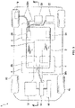
- FIG. 1 is a layout view, seen from above, of a vehicle incorporating the battery device for a vehicle.
- FIG. 2 is a perspective view of the battery device for a vehicle.
- FIG. 3 is a sectional view, along the III-III line in FIG 1 , of the vehicle incorporating the battery device for a vehicle.
- FIG. 4 is a sectional view, along the IV-IV line in FIG 3 , of the vehicle incorporating the battery device for a vehicle.
- the battery device for a vehicle is mounted in a lower portion of a vehicle 1, and is connected to one or more various electric devices mounted on the vehicle 1.
- a battery device 2 for a vehicle is configured in a roughly rectangular shape in a top view, and is particularly disposed at the center in the lower portion of the vehicle 1. That is, the battery device 2 for a vehicle particularly extends from the lower side of front seats 4 of the vehicle 1 to the vicinity of the lower side of a rear seat 6, and is disposed at the center in a vehicle width direction.
- a tunnel portion 8 is particularly provided at the center in the width direction of the lower portion of the vehicle 1 so as to extend in a front-rear direction, and the battery device 2 for a vehicle is particularly disposed under the tunnel portion 8. That is, the tunnel portion 8 is formed to extend from the front portion of the vehicle 1 through a space between the front seats 4 to the vicinity of the rear seat 6.
- a drive motor 12 that is an electric motor for driving front wheels 10 of the vehicle 1, an inverter 14 for converting DC power to alternating current, a DC-to-DC converter 16 for converting DC voltage, etc.
- a side surface in a rear portion of the vehicle 1 is particularly provided with a charging port 18 to which a charging plug (not shown) of a charging station is to be connected for charging the battery device 2 for a vehicle.
- a charger 20 that is an electric device for charging the battery device 2 for a vehicle, and a power feeder 22 are disposed in the rear portion of the vehicle 1.
- the charging port 18, the charger 20 and the power feeder 22 function as a charging device for charging the battery device 2 for a vehicle.
- the battery device 2 for a vehicle particularly includes a first relay device 24, a second relay device 26 and a battery controller 28 which are configured to switch connection and disconnection between the battery device 2 for a vehicle and an electric device mounted on the vehicle 1 as described later.
- the first relay device 24 is incorporated in a side surface in a rear portion of the battery device 2 for a vehicle, and is connected to the charging port 18, the charger 20 and the power feeder 22 disposed in the rear portion of the vehicle 1.
- the second relay device 26 is particularly incorporated in the center of a front end portion of the battery device 2 for a vehicle, and is connected to the drive motor 12, the inverter 14 and the DC-to-DC converter 16 disposed in the front portion of the vehicle 1.
- the battery controller 28 is incorporated in an opposite side surface to the first relay device 24 in the rear portion of the battery device 2 for a vehicle, and is configured to control the first relay device 24.
- the first relay device 24 is at one side of the battery device 2 and the battery controller 28 is at the other side of the battery device 2.
- the first relay device 24 is connected to the charging port 18, the charger 20 and the power feeder 22 with a wire harness 30a
- the second relay device 26 is connected to the drive motor 12, the inverter 14 and the DC-to-DC converter 16 with a wire harness 30b.
- the wire harness 30a for connecting these devices can be shortened, and transmission loss of electric power can be reduced.
- the "relay device” includes a jumper wire, a junction box or the like that switches connection and disconnection by attaching or removing a fuse or the like.
- the battery device 2 for a vehicle particularly has a battery body 32 in the shape of a roughly rectangular plate as a whole.
- the battery body 32 particularly is arranged such that the left side in FIG. 2 faces forward of the vehicle 1, and the right side faces backward of the vehicle 1.
- a table-like portion 32a raised in height is formed, the rear seat 6 (not shown) of the vehicle 1 is disposed above the table-like portion 32a.
- the battery body 32 is covered with a battery case 34, and the battery case 34 is constituted by a lower tray 34a disposed on the lower side and an upper cover 34b disposed on the upper side.
- a service plug 36 that is a high-voltage circuit breaker is particularly provided adjacent to a front side of the table-like portion 32a.
- the service plug 36 is provided to protrude upward at the center in the vehicle width direction of the upper surface of the battery body 32. Therefore, as shown in FIG. 3 , the service plug 36 is disposed to protrude into the tunnel portion 8 provided at the center in the lower portion of the vehicle 1.
- the service plug 36 is positioned in front of the rear seat 6 (not shown) of the vehicle 1.
- the left side in FIG. 3 corresponds to the front side of the vehicle 1, and the right side corresponds to the rear side of the vehicle 1.
- a protruding portion 38 is particularly formed in a front end portion of the battery body 32 at the center in the vehicle width direction.
- the protruding portion 38 is formed by raising upward a central portion in the vehicle width direction of the upper cover 34b that forms the upper surface of the battery body 32.
- the protruding portion 38 is disposed on the front side of the vehicle 1 relative to the service plug 36 so as to close the cross section of the tunnel portion 8 in the vehicle width direction. That is, as shown in FIG.
- the tunnel portion 8 is formed by raising a floor surface of the vehicle 1 upward, and the protruding portion 38 of the battery body 32 protrudes from the lower side into the tunnel portion 8 formed in this manner. Consequently, the cross section in the vehicle width direction of the tunnel portion 8 is closed with the protruding portion 38 on the front side of the vehicle relative to the service plug 36, thereby preventing entry of a foreign object into the tunnel portion 8.
- the protruding portion 38 closes most of the cross section in the vehicle width direction of the tunnel portion 8, but the effect of preventing the entry of a foreign object can be obtained as long as the protruding portion 38 protrudes into the tunnel portion 8 and closes at least a part of the cross section in the vehicle width direction of the tunnel portion 8.
- the protruding portion 38 is configured to close a half or more of the cross section in the vehicle width direction of the tunnel portion 8.
- a connector portion 40 is particularly provided on an end surface of the protruding portion 38 on the front side of the vehicle, and the battery device 2 for a vehicle is electrically connected through the connector portion 40 to the drive motor 12 or the like that is an electric device mounted on the vehicle 1.
- the wire harness 30b is connected to the connector portion 40, electrical energy accumulated in the battery device 2 for a vehicle is supplied from the connector portion 40 to the inverter 14, etc. through the wire harness 30b, and the drive motor 12 is driven.
- the second relay device 26 is particularly incorporated in the battery case 34 below the connector portion 40 provided in the protruding portion 38.
- the second relay device 26 is disposed in a front end portion of the battery case 34 in a front-rear direction of the vehicle 1, and switches an electrical connection between the battery device 2 for a vehicle and the drive motor 12, etc.
- FIG. 5 is a perspective view showing the battery device for a vehicle in a state in which the upper cover has been removed.
- FIG. 6 is a top view showing the battery device for a vehicle in a state in which the upper cover has been removed.
- FIG. 7 is a view showing a support structure of the service plug.
- each battery module 42 has a roughly rectangular parallelepiped shape, and is particularly arranged such that the long sides are oriented in the front-rear direction of the vehicle 1.
- the battery modules 42 on the upper level are disposed, respectively. That is, four battery modules 42 are disposed in the vehicle width direction on the upper level.
- the table-like portion 32a ( FIG. 2 ) is formed to cover the battery modules 42 disposed on the upper level, and the height of this portion is higher.
- a total of 16 battery modules 42 are disposed in the battery case 34.
- the number of the battery modules 42 are not limited to 16.
- These battery modules 42 are electrically connected in series with bus bars 42a.
- the service plug 36 is disposed at the center in the vehicle width direction and adjacent to the front side of the four battery modules 42 disposed on the upper level. By pulling out the service plug 36, the connection between the battery modules 42 connected in series is disconnected at one point, and a high voltage does not act on the connector portion 40.
- the service plug 36 is particularly disposed above some of the battery modules 42, and is disposed at a position overlapping some of the battery modules 42 in an up-down direction. As shown in FIG. 6 , in the present embodiment, the service plug 36 overlaps, in the up-down direction, a part of two battery modules 42 positioned at the center in the vehicle width direction of the row in the middle in the front-rear direction of the vehicle 1.
- the service plug 36 is particularly supported by a support member 44 with respect to the lower tray 34a of the battery case 34.
- the support member 44 particularly includes a flat plate portion 44a formed in a flat plate shape, and one or more, particularly three leg portions 44b, 44c, 44d extending downward from the flat plate portion 44a.
- the service plug 36 is attached to the flat plate portion 44a and supported above the battery modules 42. Of the three legs, two legs 44b and 44d on the rear side of the vehicle 1 are supported above the lower tray 34a behind the battery modules 42.
- One leg portion 44c on the front side of the vehicle 1 is attached to the lower tray 34a of the battery case 34, extends upward between the two battery modules 42, and supports the service plug 36 through the flat plate portion 44a above the battery modules 42.
- the service plug 36 is supported on the lower tray 34a through the support member 44, it is possible to dispose the battery modules 42 on the lower tray 34a in a state in which the upper cover 34b has been removed, and it is possible to attach the service plug 36, thereby improving assembling performance.
- the first relay device 24 is disposed on a side in the vehicle width direction of the portion where the battery modules 42 are stacked in two levels. That is, in a side view of the vehicle 1, the first relay device 24 is disposed to overlap with the battery modules 42 stacked in two levels.
- the battery modules 42 incorporated in the battery device 2 for a vehicle are connected to the charging port 18, the charger 20 and the power feeder 22 ( FIG. 1 ) as the charging device through the first relay device 24 and the wire harness 30a.
- the first relay device 24 is configured to switch connection and disconnection between the battery modules 42 and the charging port 18, the charger 20 and/or the power feeder 22 disposed behind the battery device 2 for a vehicle to charge the battery modules 42.
- the battery controller 28 is particularly disposed on the opposite side to the first relay device 24, of the portion where the battery modules 42 are stacked in two levels. That is, the battery controller 28 is disposed on the opposite side to the first relay device 24 with respect to the battery modules 42 in the vehicle width direction. Therefore, the battery modules 42 are located between the first relay device 24 and the battery controller 28 in the vehicle width direction.
- the battery controller 28 is particularly, configured to control the first relay device 24 by sending a control signal to the first relay device 24.
- the first relay device 24 and the battery controller 28 are disposed, on both sides of the portion where the battery modules 42 are stacked in a plurality of levels, so as to overlap with the battery modules 42 in a side view of the vehicle 1.
- the first relay device 24 and the battery controller 28 can be compactly accommodated in the battery case 34, and the projected area of the battery device 2 for a vehicle in a side view can be reduced.
- the battery modules 42 on the upper level are arranged so as to be slightly offset or shifted toward the rear side of the vehicle 1 relative to the battery modules 42 disposed on the lower level.
- a wire harness 46 is disposed to extend in the vehicle width direction. The wire harness 46 is provided for connecting the battery modules 42 to each other in the battery case 34.
- the first relay device 24 is disposed on a side in the vehicle width direction of the portion where the battery modules 42 are stacked in a plurality of levels ( FIG. 5 ), it is possible to miniaturize the battery device 2 for a vehicle while including the relay device.
- the second relay device 26 is provided separately from the first relay device 24, and the second relay device 26 is disposed in the front end portion of the battery case 34 in the front-rear direction of the vehicle ( FIG. 5 ). Hence, it is possible to miniaturize individual relay devices, and it is possible to effectively utilize small empty space in the battery case 34.
- the wire harness 30a that connects the battery modules 42 and the charging device can be shortened, and transmission loss of electric power can be reduced.
- the battery controller 28 since the battery controller 28 is disposed on the opposite side of the first relay device 24 with respect to the battery modules 42 in the vehicle width direction ( FIG. 6 ), the battery controller 28 can also be compactly accommodated in the battery case 34.
- the first relay device 24 is disposed to overlap with the battery modules 42 stacked in a plurality of levels ( FIG. 5 ), and therefore it is possible to reduce the projected area of the battery device 2 for a vehicle in the side view.
- the wire harness 46 is disposed in the space produced by shifting the battery modules 42 on the upper level toward the rear side ( FIG. 3 ), even if the vehicle 1 collides, the wire harness 46 is less likely damaged, and the wire harness 46 can be protected.
- the service plug 36 is disposed above the battery modules 42, at a position where the service plug 36 overlaps the battery modules 42 in the up-down direction, but it is possible to dispose the service plug 36 under the battery modules 42.
- the front of the tunnel portion 8 is closed by only the protruding portion 38, but, as a modification, another configuration can be added to the protruding portion so as to close the cross section in the vehicle width direction of the tunnel portion 8.
- FIG. 8 is a sectional view of the vehicle on which a battery device for a vehicle according to a modification of the embodiment is mounted.
- a hanging portion 48 is formed in the tunnel portion 8, and the cross section in the vehicle width direction of the tunnel portion 8 is closed by the protruding portion 38 and the hanging portion 48. That is, the tunnel portion 8 is formed by a thin plate curved in an inverted U shape, and the protruding portion 38 of the battery device for a vehicle is disposed to protrude into the tunnel portion 8 from the lower side.
- the hanging portion 48 is formed by a thin plate attached to an upper portion inside the tunnel portion 8, and hangs and extends downward from the vicinity of a top portion in the tunnel portion 8.
- the hanging portion 48 is provided at a position behind the protruding portion 38 and in front of the service plug 36 in the front-rear direction of the vehicle 1.
- the cross section in the vehicle width direction of the tunnel portion 8 is closed by the hanging portion 48 hanging downward from the vicinity of the top portion in the tunnel portion 8 as well as by the protruding portion 38 disposed to protrude upward from the lower end of the tunnel portion 8.
- the hanging portion 48 is provided in the tunnel portion 8, even when a foreign object enters from a gap between an inner wall surface of the tunnel portion 8 and the protruding portion 38, it is possible to stop the foreign object by the hanging portion 48 and more reliably protect the service plug 36.
Landscapes
- Engineering & Computer Science (AREA)
- Chemical & Material Sciences (AREA)
- General Chemical & Material Sciences (AREA)
- Electrochemistry (AREA)
- Chemical Kinetics & Catalysis (AREA)
- Transportation (AREA)
- Mechanical Engineering (AREA)
- Power Engineering (AREA)
- Life Sciences & Earth Sciences (AREA)
- Sustainable Energy (AREA)
- Sustainable Development (AREA)
- Aviation & Aerospace Engineering (AREA)
- Manufacturing & Machinery (AREA)
- Combustion & Propulsion (AREA)
- Microelectronics & Electronic Packaging (AREA)
- Arrangement Or Mounting Of Propulsion Units For Vehicles (AREA)
- Electric Propulsion And Braking For Vehicles (AREA)
- Battery Mounting, Suspending (AREA)
Description
- The present invention relates to a vehicle. The present invention particularly relates to a vehicle with a battery device mounted in a lower portion of the vehicle.
-
Japanese Patent No. 5776852 Patent Literature 1, a battery pack is disposed under a passenger seat, and a high-voltage harness extends from a front end portion of the battery pack and is connected to an inverter, etc. disposed in front of a driver seat. Further, a junction box is incorporated in the front end portion of the battery pack to switch an electrical connection between the battery pack and an externally connected device. - That is, the junction box incorporated in the battery pack is configured to supply, shut off, and distribute high voltage by a relay circuit. The junction box and a power module of the vehicle are connected through a connector terminal and a harness.
- Thus, there are a number of ancillary instruments such as the junction box (relay device) needed to be included in a battery device, and providing such instruments causes a problem of an increase in the size of the battery device.
-
US 2011/297467 A1 describes that a plurality of batteries are disposed under a floor panel of a vehicle. A first battery unit comprising a plurality of batteries stacked in a vertical direction and a second battery unit comprising a plurality of batteries stacked in a vehicle transverse direction are provided. - Therefore, an object of the present invention is to provide a battery device for a vehicle, which can be miniaturized while including ancillary instruments such as a relay device.
- In order to solve the above problem, the present invention provides a vehicle as defined in
claim 1. Preferred embodiments are defined in dependent claims. - According to the present invention, since the first relay device is disposed on a side in the vehicle width direction of the portion where the battery modules are stacked in a plurality of levels, it is possible to miniaturize the battery device for a vehicle while including the relay device.
- According to the invention, the battery device for a vehicle includes the second relay device separately from the first relay device, and the second relay device is disposed in the front end portion of the battery case in the front-rear direction of the vehicle. Therefore, it is possible to miniaturize individual relay devices, and it is possible to effectively utilize small empty space in the battery case.
- According to the invention, since connection and disconnection between the battery modules and the charging device disposed on the rear side of the battery device for a vehicle are switched by the first relay device, a harness that connects the battery modules and the charging device can be shortened, and transmission loss of electric power can be reduced.
- Particularly, the battery modules is disposed between the battery controller and the first relay device in the vehicle width direction.
- According to the invention, since the battery controller is disposed on the opposite side to the first relay device with respect to the battery modules in the vehicle width direction, the battery controller can also be compactly accommodated in the battery case.
- According to the invention, in the side view of the vehicle, since the first relay device is disposed to overlap with the battery modules stacked in a plurality of levels, it is possible to reduce the projected area of the battery device for a vehicle in the side view.
- Particularly, in the portion where the battery modules are stacked in a plurality of levels, the battery modules on an upper side are disposed so as to be offset or shifted toward the rear side of the vehicle in the vehicle front-rear direction relative to the battery modules on a lower side. Further particularly, a wire harness to be connected to the first relay device is disposed in a space produced by offsetting or shifting the battery modules on the upper side toward the rear side. Further particularly, a wire harness to be connected to the first relay device is disposed in front of the battery modules on the upper side of the battery module stacked in the plurality of levels and above the battery modules on the lower side of the battery module stacked in the plurality of levels.
- According to the embodiment thus configured, since the wire harness is disposed in the space produced by shifting the battery modules on the upper side toward the rear side, even if the vehicle collides, the wire harness is less likely damaged, and it is possible to protect the wire harness.
- Particularly, the wire harness is configured to connect the battery modules each other.
- According to the present invention, it is possible to miniaturize a battery device for a vehicle while including ancillary instruments such as a relay device.
-
-
FIG. 1 is a layout view, seen from above, of a vehicle incorporating a battery device for a vehicle; -
FIG. 2 is a perspective view of the battery device for a vehicle; -
FIG. 3 is a sectional view, along the III-III line inFIG 1 , of the vehicle incorporating the battery device for a vehicle; -
FIG. 4 is a sectional view, along the IV-IV line inFIG 3 , of the vehicle incorporating the battery device for a vehicle; -
FIG. 5 is a perspective view of the battery device for a vehicle in a state in which an upper cover has been removed; -
FIG. 6 is a top view of the battery device for a vehicle in a state in which the upper cover has been removed; -
FIG. 7 is a view showing a support structure of a service plug in the battery device for a vehicle; and -
FIG. 8 is a sectional view of a vehicle incorporating a battery device for a vehicle according to a modification. - Next, a battery device for a vehicle of an embodiment of the present invention will be described with reference to the attached drawings.
-
FIG. 1 is a layout view, seen from above, of a vehicle incorporating the battery device for a vehicle.FIG. 2 is a perspective view of the battery device for a vehicle.FIG. 3 is a sectional view, along the III-III line inFIG 1 , of the vehicle incorporating the battery device for a vehicle.FIG. 4 is a sectional view, along the IV-IV line inFIG 3 , of the vehicle incorporating the battery device for a vehicle. - As shown in
FIG. 1 , the battery device for a vehicle is mounted in a lower portion of avehicle 1, and is connected to one or more various electric devices mounted on thevehicle 1. Specifically, abattery device 2 for a vehicle is configured in a roughly rectangular shape in a top view, and is particularly disposed at the center in the lower portion of thevehicle 1. That is, thebattery device 2 for a vehicle particularly extends from the lower side offront seats 4 of thevehicle 1 to the vicinity of the lower side of a rear seat 6, and is disposed at the center in a vehicle width direction. Atunnel portion 8 is particularly provided at the center in the width direction of the lower portion of thevehicle 1 so as to extend in a front-rear direction, and thebattery device 2 for a vehicle is particularly disposed under thetunnel portion 8. That is, thetunnel portion 8 is formed to extend from the front portion of thevehicle 1 through a space between thefront seats 4 to the vicinity of the rear seat 6. - Disposed particularly in the front portion of the
vehicle 1 are adrive motor 12 that is an electric motor for drivingfront wheels 10 of thevehicle 1, aninverter 14 for converting DC power to alternating current, a DC-to-DC converter 16 for converting DC voltage, etc. Moreover, a side surface in a rear portion of thevehicle 1 is particularly provided with acharging port 18 to which a charging plug (not shown) of a charging station is to be connected for charging thebattery device 2 for a vehicle. Furthermore, acharger 20 that is an electric device for charging thebattery device 2 for a vehicle, and apower feeder 22 are disposed in the rear portion of thevehicle 1. Thecharging port 18, thecharger 20 and thepower feeder 22 function as a charging device for charging thebattery device 2 for a vehicle. - The
battery device 2 for a vehicle particularly includes afirst relay device 24, asecond relay device 26 and abattery controller 28 which are configured to switch connection and disconnection between thebattery device 2 for a vehicle and an electric device mounted on thevehicle 1 as described later. In the present embodiment, thefirst relay device 24 is incorporated in a side surface in a rear portion of thebattery device 2 for a vehicle, and is connected to thecharging port 18, thecharger 20 and thepower feeder 22 disposed in the rear portion of thevehicle 1. Thesecond relay device 26 is particularly incorporated in the center of a front end portion of thebattery device 2 for a vehicle, and is connected to thedrive motor 12, theinverter 14 and the DC-to-DC converter 16 disposed in the front portion of thevehicle 1. Thebattery controller 28 is incorporated in an opposite side surface to thefirst relay device 24 in the rear portion of thebattery device 2 for a vehicle, and is configured to control thefirst relay device 24. In other words, in the vehicle width direction, thefirst relay device 24 is at one side of thebattery device 2 and thebattery controller 28 is at the other side of thebattery device 2. - Further, the
first relay device 24 is connected to thecharging port 18, thecharger 20 and thepower feeder 22 with awire harness 30a, and thesecond relay device 26 is connected to thedrive motor 12, theinverter 14 and the DC-to-DC converter 16 with awire harness 30b. Thus, since thefirst relay device 24 provided on a side in the rear portion of thebattery device 2 for a vehicle is connected to thecharging port 18, thecharger 20 and thepower feeder 22 disposed behind thebattery device 2 for a vehicle, thewire harness 30a for connecting these devices can be shortened, and transmission loss of electric power can be reduced. In the present specification, the "relay device" includes a jumper wire, a junction box or the like that switches connection and disconnection by attaching or removing a fuse or the like. - Next, the
battery device 2 for a vehicle of the embodiment will be described with reference toFIGS. 2 to 4 . - As shown in
FIG. 2 , thebattery device 2 for a vehicle particularly has abattery body 32 in the shape of a roughly rectangular plate as a whole. Thebattery body 32 particularly is arranged such that the left side inFIG. 2 faces forward of thevehicle 1, and the right side faces backward of thevehicle 1. In roughly one fourth of the region on the rear side of an upper surface of thebattery body 32, a table-like portion 32a raised in height is formed, the rear seat 6 (not shown) of thevehicle 1 is disposed above the table-like portion 32a. Thebattery body 32 is covered with abattery case 34, and thebattery case 34 is constituted by alower tray 34a disposed on the lower side and anupper cover 34b disposed on the upper side. - Furthermore, on the upper surface of the
battery body 32, aservice plug 36 that is a high-voltage circuit breaker is particularly provided adjacent to a front side of the table-like portion 32a. In order to shut off an electric circuit in thebattery body 32, theservice plug 36 is provided to protrude upward at the center in the vehicle width direction of the upper surface of thebattery body 32. Therefore, as shown inFIG. 3 , theservice plug 36 is disposed to protrude into thetunnel portion 8 provided at the center in the lower portion of thevehicle 1. In the present embodiment, according to such a layout, theservice plug 36 is positioned in front of the rear seat 6 (not shown) of thevehicle 1. Hence, by opening a floor member in this portion of a passenger compartment, it is possible to easily access the service plug 36 from the passenger compartment. The left side inFIG. 3 corresponds to the front side of thevehicle 1, and the right side corresponds to the rear side of thevehicle 1. - On the upper surface of the
battery body 32, a protrudingportion 38 is particularly formed in a front end portion of thebattery body 32 at the center in the vehicle width direction. The protrudingportion 38 is formed by raising upward a central portion in the vehicle width direction of theupper cover 34b that forms the upper surface of thebattery body 32. Thus, as shown inFIGS. 3 and4 , the protrudingportion 38 is disposed on the front side of thevehicle 1 relative to theservice plug 36 so as to close the cross section of thetunnel portion 8 in the vehicle width direction. That is, as shown inFIG. 4 , thetunnel portion 8 is formed by raising a floor surface of thevehicle 1 upward, and the protrudingportion 38 of thebattery body 32 protrudes from the lower side into thetunnel portion 8 formed in this manner. Consequently, the cross section in the vehicle width direction of thetunnel portion 8 is closed with the protrudingportion 38 on the front side of the vehicle relative to theservice plug 36, thereby preventing entry of a foreign object into thetunnel portion 8. - In the present embodiment, as shown in
FIG. 4 , the protrudingportion 38 closes most of the cross section in the vehicle width direction of thetunnel portion 8, but the effect of preventing the entry of a foreign object can be obtained as long as the protrudingportion 38 protrudes into thetunnel portion 8 and closes at least a part of the cross section in the vehicle width direction of thetunnel portion 8. Particularly, the protrudingportion 38 is configured to close a half or more of the cross section in the vehicle width direction of thetunnel portion 8. - As shown in
FIGS. 3 and4 , aconnector portion 40 is particularly provided on an end surface of the protrudingportion 38 on the front side of the vehicle, and thebattery device 2 for a vehicle is electrically connected through theconnector portion 40 to thedrive motor 12 or the like that is an electric device mounted on thevehicle 1. Specifically, thewire harness 30b is connected to theconnector portion 40, electrical energy accumulated in thebattery device 2 for a vehicle is supplied from theconnector portion 40 to theinverter 14, etc. through thewire harness 30b, and thedrive motor 12 is driven. - Further, the
second relay device 26 is particularly incorporated in thebattery case 34 below theconnector portion 40 provided in the protrudingportion 38. In the present embodiment, thesecond relay device 26 is disposed in a front end portion of thebattery case 34 in a front-rear direction of thevehicle 1, and switches an electrical connection between thebattery device 2 for a vehicle and thedrive motor 12, etc. Thus, by providing thesecond relay device 26 to be connected to thedrive motor 12, etc. separately from thefirst relay device 24 to be connected to thecharger 20, etc., it is possible to miniaturize individual relay devices, and it is possible to accommodate the relay devices by utilizing small empty spaces in thebattery case 34. - Next, an internal structure of the battery device for a vehicle will be described with reference to
FIGS. 5 to 7 . -
FIG. 5 is a perspective view showing the battery device for a vehicle in a state in which the upper cover has been removed.FIG. 6 is a top view showing the battery device for a vehicle in a state in which the upper cover has been removed.FIG. 7 is a view showing a support structure of the service plug. - As shown in
FIG. 5 , a plurality ofbattery modules 42 are arranged and accommodated in thebattery case 34, and all or some of thebattery modules 42 are stacked in two or more levels, particularly two levels. None or some of thebattery modules 42 are arranged in a single level without stacking the battery modules (42). In the present embodiment, eachbattery module 42 has a roughly rectangular parallelepiped shape, and is particularly arranged such that the long sides are oriented in the front-rear direction of thevehicle 1. On the lower level of the array of thebattery modules 42, a total of twelvebattery modules 42, four in the vehicle width direction and three in the front-rear direction of thevehicle 1, are arranged. On thebattery modules 42 in one row on the rear side of thevehicle 1 among thebattery modules 42 disposed on the lower level, thebattery modules 42 on the upper level are disposed, respectively. That is, fourbattery modules 42 are disposed in the vehicle width direction on the upper level. The table-like portion 32a (FIG. 2 ) is formed to cover thebattery modules 42 disposed on the upper level, and the height of this portion is higher. - Thus, in the present embodiment, a total of 16
battery modules 42 are disposed in thebattery case 34. The number of thebattery modules 42 are not limited to 16. Thesebattery modules 42 are electrically connected in series withbus bars 42a. The service plug 36 is disposed at the center in the vehicle width direction and adjacent to the front side of the fourbattery modules 42 disposed on the upper level. By pulling out theservice plug 36, the connection between thebattery modules 42 connected in series is disconnected at one point, and a high voltage does not act on theconnector portion 40. - As shown in
FIG. 6 , theservice plug 36 is particularly disposed above some of thebattery modules 42, and is disposed at a position overlapping some of thebattery modules 42 in an up-down direction. As shown inFIG. 6 , in the present embodiment, theservice plug 36 overlaps, in the up-down direction, a part of twobattery modules 42 positioned at the center in the vehicle width direction of the row in the middle in the front-rear direction of thevehicle 1. - Next, as shown in
FIG. 7 , theservice plug 36 is particularly supported by asupport member 44 with respect to thelower tray 34a of thebattery case 34. That is, thesupport member 44 particularly includes aflat plate portion 44a formed in a flat plate shape, and one or more, particularly threeleg portions flat plate portion 44a. The service plug 36 is attached to theflat plate portion 44a and supported above thebattery modules 42. Of the three legs, twolegs vehicle 1 are supported above thelower tray 34a behind thebattery modules 42. Oneleg portion 44c on the front side of thevehicle 1 is attached to thelower tray 34a of thebattery case 34, extends upward between the twobattery modules 42, and supports theservice plug 36 through theflat plate portion 44a above thebattery modules 42. Thus, in the present embodiment, since theservice plug 36 is supported on thelower tray 34a through thesupport member 44, it is possible to dispose thebattery modules 42 on thelower tray 34a in a state in which theupper cover 34b has been removed, and it is possible to attach theservice plug 36, thereby improving assembling performance. - Moreover, as shown in
FIG. 5 , thefirst relay device 24 is disposed on a side in the vehicle width direction of the portion where thebattery modules 42 are stacked in two levels. That is, in a side view of thevehicle 1, thefirst relay device 24 is disposed to overlap with thebattery modules 42 stacked in two levels. Thebattery modules 42 incorporated in thebattery device 2 for a vehicle are connected to the chargingport 18, thecharger 20 and the power feeder 22 (FIG. 1 ) as the charging device through thefirst relay device 24 and thewire harness 30a. Thefirst relay device 24 is configured to switch connection and disconnection between thebattery modules 42 and the chargingport 18, thecharger 20 and/or thepower feeder 22 disposed behind thebattery device 2 for a vehicle to charge thebattery modules 42. - Further, as shown in
FIG. 5 , thebattery controller 28 is particularly disposed on the opposite side to thefirst relay device 24, of the portion where thebattery modules 42 are stacked in two levels. That is, thebattery controller 28 is disposed on the opposite side to thefirst relay device 24 with respect to thebattery modules 42 in the vehicle width direction. Therefore, thebattery modules 42 are located between thefirst relay device 24 and thebattery controller 28 in the vehicle width direction. Thebattery controller 28 is particularly, configured to control thefirst relay device 24 by sending a control signal to thefirst relay device 24. Thus, thefirst relay device 24 and thebattery controller 28 are disposed, on both sides of the portion where thebattery modules 42 are stacked in a plurality of levels, so as to overlap with thebattery modules 42 in a side view of thevehicle 1. Hence, thefirst relay device 24 and thebattery controller 28 can be compactly accommodated in thebattery case 34, and the projected area of thebattery device 2 for a vehicle in a side view can be reduced. - Next, as shown in
FIG. 3 , in the portion where thebattery modules 42 are stacked in two levels, thebattery modules 42 on the upper level are arranged so as to be slightly offset or shifted toward the rear side of thevehicle 1 relative to thebattery modules 42 disposed on the lower level. In a space produced by shifting thebattery modules 42 on the upper level toward the rear side in such a manner (the space in front of thebattery modules 42 on the upper level), awire harness 46 is disposed to extend in the vehicle width direction. Thewire harness 46 is provided for connecting thebattery modules 42 to each other in thebattery case 34. Thus, by shifting thebattery modules 42 on the upper level toward the rear side and disposing thewire harness 46 in the space produced by the shifting toward the rear side, it is possible to reduce the risk of damage to thewire harness 46 caused by being caught between thebattery modules 42 in the event of a collision of thevehicle 1 or the like. - According to the
battery device 2 for a vehicle of the embodiment, since thefirst relay device 24 is disposed on a side in the vehicle width direction of the portion where thebattery modules 42 are stacked in a plurality of levels (FIG. 5 ), it is possible to miniaturize thebattery device 2 for a vehicle while including the relay device. - Moreover, according to the
battery device 2 for a vehicle of the present embodiment, thesecond relay device 26 is provided separately from thefirst relay device 24, and thesecond relay device 26 is disposed in the front end portion of thebattery case 34 in the front-rear direction of the vehicle (FIG. 5 ). Hence, it is possible to miniaturize individual relay devices, and it is possible to effectively utilize small empty space in thebattery case 34. - Further, according to the
battery device 2 for a vehicle of the present embodiment, since connection and disconnection between thebattery modules 42 and the chargingport 18, thecharger 20 and thepower feeder 22 as the charging device disposed behind thebattery device 2 for a vehicle are switched by thefirst relay device 24, thewire harness 30a that connects thebattery modules 42 and the charging device can be shortened, and transmission loss of electric power can be reduced. - According to the
battery device 2 for a vehicle of the present embodiment, since thebattery controller 28 is disposed on the opposite side of thefirst relay device 24 with respect to thebattery modules 42 in the vehicle width direction (FIG. 6 ), thebattery controller 28 can also be compactly accommodated in thebattery case 34. - Furthermore, according to the
battery device 2 for a vehicle of the present embodiment, in a side view of thevehicle 1, thefirst relay device 24 is disposed to overlap with thebattery modules 42 stacked in a plurality of levels (FIG. 5 ), and therefore it is possible to reduce the projected area of thebattery device 2 for a vehicle in the side view. - According to the
battery device 2 for a vehicle of the present embodiment, since thewire harness 46 is disposed in the space produced by shifting thebattery modules 42 on the upper level toward the rear side (FIG. 3 ), even if thevehicle 1 collides, thewire harness 46 is less likely damaged, and thewire harness 46 can be protected. - The embodiment was described above, but it is possible to add various changes to the above-described embodiment. For example, in the above-described embodiment, the
service plug 36 is disposed above thebattery modules 42, at a position where theservice plug 36 overlaps thebattery modules 42 in the up-down direction, but it is possible to dispose theservice plug 36 under thebattery modules 42. - In the above-described embodiment, the front of the
tunnel portion 8 is closed by only the protrudingportion 38, but, as a modification, another configuration can be added to the protruding portion so as to close the cross section in the vehicle width direction of thetunnel portion 8. -
FIG. 8 is a sectional view of the vehicle on which a battery device for a vehicle according to a modification of the embodiment is mounted. As shown inFIG. 8 , in this modification, a hangingportion 48 is formed in thetunnel portion 8, and the cross section in the vehicle width direction of thetunnel portion 8 is closed by the protrudingportion 38 and the hangingportion 48. That is, thetunnel portion 8 is formed by a thin plate curved in an inverted U shape, and the protrudingportion 38 of the battery device for a vehicle is disposed to protrude into thetunnel portion 8 from the lower side. The hangingportion 48 is formed by a thin plate attached to an upper portion inside thetunnel portion 8, and hangs and extends downward from the vicinity of a top portion in thetunnel portion 8. The hangingportion 48 is provided at a position behind the protrudingportion 38 and in front of theservice plug 36 in the front-rear direction of thevehicle 1. - Hence, the cross section in the vehicle width direction of the
tunnel portion 8 is closed by the hangingportion 48 hanging downward from the vicinity of the top portion in thetunnel portion 8 as well as by the protrudingportion 38 disposed to protrude upward from the lower end of thetunnel portion 8. Thus, since the hangingportion 48 is provided in thetunnel portion 8, even when a foreign object enters from a gap between an inner wall surface of thetunnel portion 8 and the protrudingportion 38, it is possible to stop the foreign object by the hangingportion 48 and more reliably protect theservice plug 36. -
- 1
- Vehicle
- 2
- Battery device for a vehicle
- 4
- Front seat
- 6
- Rear seat
- 8
- Tunnel portion
- 10
- Front wheel
- 12
- Drive motor (electric device, electric motor)
- 14
- Inverter (electric device)
- 16
- DC-to-DC converter (electric device)
- 18
- Charging port (electric device, charging device)
- 20
- Charger (electric device, charging device)
- 22
- Power feeder (electric device, charging device)
- 24
- First relay device
- 26
- Second relay device
- 28
- Battery controller
- 30a
- Wire harness
- 30b
- Wire harness
- 32
- Battery body
- 32a
- Table-like portion
- 34
- Battery case
- 34a
- Lower tray
- 34b
- Upper cover
- 36
- Service plug (high-voltage circuit breaker)
- 38
- Protruding portion
- 40
- Connector portion
- 42
- Battery module
- 44
- Support member
- 44a
- Flat plate portion
- 44b
- Leg portion
- 44c
- Leg portion
- 44d
- Leg portion
- 46
- Wire harness
- 48
- Hanging portion
Claims (3)
- A vehicle (1) comprising:a battery device (2) mounted in a lower portion of the vehicle (1);an electric motor (12) for driving front wheels (10) of the vehicle (1); andan inverter (14) for converting DC power to alternating current;wherein the electric motor (12) and the inverter (14) are disposed in a front portion of the vehicle (1),wherein the battery device (2) comprising:a battery case (34);a plurality of battery modules (42) accommodated in the battery case (34) and arranged such that at least some of the battery modules (42) are stacked in a plurality of levels in a vehicle up-down direction; anda first relay device (24),wherein the first relay device (24) is disposed on a side, in a vehicle width direction, of a portion where the battery modules (42) are stacked in the plurality of levels, andwherein the vehicle (1) is provided with a charging device (20, 22) configured to charge the battery modules (42),characterized in thatthe charging device (20, 22) is disposed on a rear side of the vehicle (1) relative to the battery device (2),the first relay device (24) is configured to switch connection and disconnection between the charging device (20, 22) and the battery modules (42),the battery device (2) further comprises a battery controller (28) configured to control the first relay device (24),the battery controller (28) is disposed on an opposite side to the first relay device (24) with respect to the battery modules (42) in the vehicle width direction,the first relay device (24) is incorporated in a side surface in a rear portion of the battery device (2),the battery controller (28) is incorporated in an opposite side surface to the first relay device (24) in the rear portion of the battery device (2),the first relay device (24) and the battery controller (28) are disposed, on both sides of the portion where the battery modules (42) are stacked in the plurality of levels, so as to overlap with the battery modules (42) in a side view of the vehicle (1),the battery device further comprises a second relay device (26) configured to connect the battery modules (42) and the electric motor (12) mounted on the vehicle (1),the second relay device (26) is disposed in a front end portion of the battery case (34) in a front-rear direction of the vehicle (1),the first relay device (24) is connected to the charging device (20, 22) with a wire harness (30a), andthe second relay device (26) is connected to the electric motor (12) and the inverter (14) with a wire harness (30b).
- The vehicle (1) according to claim 1, further comprising a DC-to-DC converter (16) for converting DC voltage,
whereinthe electric motor (12), the inverter (14) and the DC-to-DC converter (16) are disposed in the front portion of the vehicle (1),in the portion where the battery modules (42) are stacked in the plurality of levels, the battery modules (42) on an upper side are disposed so as to be offset or shifted toward a rear side of the vehicle (1) in the vehicle front-rear direction relative to the battery modules (42) on a lower side,a wire harness (46) connected to the first relay device (24) is disposed in a space produced by offsetting or shifting the battery modules (42) on the upper side toward the rear side, andthe wire harness (46) is configured to connect the battery modules (42). - The vehicle (1) according to claim 2, wherein a wire harness (46) connected to the first relay device (24) is disposed in front of the battery modules (42) on the upper side of the battery module (42) stacked in the plurality of levels and above the battery modules (42) on the lower side of the battery module (42) stacked in the plurality of levels.
Applications Claiming Priority (1)
| Application Number | Priority Date | Filing Date | Title |
|---|---|---|---|
| JP2019082570A JP7316523B2 (en) | 2019-04-24 | 2019-04-24 | Vehicle battery system |
Publications (2)
| Publication Number | Publication Date |
|---|---|
| EP3730328A1 EP3730328A1 (en) | 2020-10-28 |
| EP3730328B1 true EP3730328B1 (en) | 2022-07-13 |
Family
ID=69742644
Family Applications (1)
| Application Number | Title | Priority Date | Filing Date |
|---|---|---|---|
| EP20158389.5A Active EP3730328B1 (en) | 2019-04-24 | 2020-02-20 | Vehicle comprising a battery device |
Country Status (4)
| Country | Link |
|---|---|
| US (1) | US11329343B2 (en) |
| EP (1) | EP3730328B1 (en) |
| JP (1) | JP7316523B2 (en) |
| CN (1) | CN111845383B (en) |
Families Citing this family (10)
| Publication number | Priority date | Publication date | Assignee | Title |
|---|---|---|---|---|
| JP7361673B2 (en) * | 2020-11-19 | 2023-10-16 | 本田技研工業株式会社 | Vehicles equipped with battery packs |
| JP7481235B2 (en) * | 2020-11-19 | 2024-05-10 | 本田技研工業株式会社 | Underbody structure |
| JP7559645B2 (en) * | 2021-03-26 | 2024-10-02 | マツダ株式会社 | Electric vehicle undercarriage |
| JP7501429B2 (en) * | 2021-03-30 | 2024-06-18 | マツダ株式会社 | Body structure |
| JP7528843B2 (en) * | 2021-03-30 | 2024-08-06 | マツダ株式会社 | Body structure |
| JP7669797B2 (en) * | 2021-05-25 | 2025-04-30 | マツダ株式会社 | Vehicle undercarriage |
| CN115742715A (en) * | 2021-09-06 | 2023-03-07 | 广汽埃安新能源汽车有限公司 | Electric automobile boost system arrangement structure and electric automobile |
| CN116190903B (en) * | 2021-11-29 | 2026-01-09 | 本田技研工业株式会社 | Battery pack |
| WO2023182979A1 (en) * | 2022-03-22 | 2023-09-28 | Coulomb Solutions, Inc. | Electric vehicle battery module |
| WO2025062491A1 (en) * | 2023-09-19 | 2025-03-27 | 本田技研工業株式会社 | Electric vehicle |
Family Cites Families (14)
| Publication number | Priority date | Publication date | Assignee | Title |
|---|---|---|---|---|
| JP2007069801A (en) * | 2005-09-08 | 2007-03-22 | Toyota Motor Corp | Power supply device mounting structure |
| JP4940966B2 (en) * | 2007-01-30 | 2012-05-30 | 日産自動車株式会社 | Battery mounting structure |
| JP4929116B2 (en) * | 2007-09-28 | 2012-05-09 | 株式会社アルファ | Electric steering lock device |
| JP2009292412A (en) * | 2008-06-09 | 2009-12-17 | Omron Corp | Side stand state detector |
| MY160553A (en) * | 2009-02-24 | 2017-03-15 | Nissan Motor | Vehicle battery mounting structure |
| KR101273080B1 (en) * | 2011-07-21 | 2013-06-10 | 기아자동차주식회사 | Mounting structure for battery in electric vehicle |
| JP6245789B2 (en) * | 2012-02-20 | 2017-12-13 | 日産自動車株式会社 | Electric vehicle battery pack temperature control structure |
| EP2889185B1 (en) | 2012-08-27 | 2018-02-21 | Nissan Motor Company, Limited | High-voltage harness connection structure for electric vehicle |
| JP2015026428A (en) * | 2013-07-24 | 2015-02-05 | 日産自動車株式会社 | Battery pack harness protection structure |
| JP6086604B2 (en) * | 2013-12-04 | 2017-03-01 | 本田技研工業株式会社 | Electric vehicle |
| JP6355347B2 (en) * | 2014-01-30 | 2018-07-11 | 日立建機株式会社 | Hybrid construction machine |
| JP5829706B2 (en) * | 2014-02-25 | 2015-12-09 | 富士重工業株式会社 | Automotive battery |
| JP6011949B2 (en) * | 2015-01-16 | 2016-10-25 | 富士重工業株式会社 | Automotive battery |
| JP6269559B2 (en) * | 2015-04-10 | 2018-01-31 | トヨタ自動車株式会社 | In-vehicle secondary battery cooling system |
-
2019
- 2019-04-24 JP JP2019082570A patent/JP7316523B2/en active Active
-
2020
- 2020-02-20 EP EP20158389.5A patent/EP3730328B1/en active Active
- 2020-02-28 CN CN202010126472.7A patent/CN111845383B/en active Active
- 2020-03-16 US US16/820,369 patent/US11329343B2/en active Active
Also Published As
| Publication number | Publication date |
|---|---|
| US20200343502A1 (en) | 2020-10-29 |
| EP3730328A1 (en) | 2020-10-28 |
| JP7316523B2 (en) | 2023-07-28 |
| CN111845383A (en) | 2020-10-30 |
| CN111845383B (en) | 2023-10-13 |
| US11329343B2 (en) | 2022-05-10 |
| JP2020179726A (en) | 2020-11-05 |
Similar Documents
| Publication | Publication Date | Title |
|---|---|---|
| US11329343B2 (en) | Battery device for vehicle | |
| JP6720354B2 (en) | Vehicle battery pack and automobile including the same | |
| EP2889185B1 (en) | High-voltage harness connection structure for electric vehicle | |
| US9985258B2 (en) | Onboard battery | |
| US10242835B2 (en) | Harness holder, power equipment unit, and vehicle | |
| US20110297467A1 (en) | Vehicle battery mounting structure | |
| CN111952494B (en) | Vehicle battery unit | |
| JP6688851B2 (en) | vehicle | |
| JP7742033B2 (en) | Power Control Device | |
| US11760183B2 (en) | Battery mounting system for an electric vehicle | |
| US7508164B2 (en) | Battery pack having control devices of differing heights | |
| KR102952378B1 (en) | Battery pack | |
| JP7276683B2 (en) | Vehicle battery system | |
| JP2021144827A (en) | Battery pack | |
| JP7309314B2 (en) | vehicle battery pack | |
| CN120569860A (en) | Battery power supply disconnecting device | |
| CN120584437A (en) | Battery power disconnect device | |
| JP7345730B2 (en) | Harness arrangement structure | |
| US11264678B2 (en) | Battery wiring module with partition wall separating module-side terminal and electric wire passing above partition wall | |
| US20240332701A1 (en) | Battery pack | |
| JP2022126481A (en) | Vehicle drive battery unit | |
| US20250273787A1 (en) | Battery pack | |
| JP2020179724A (en) | Vehicle battery device | |
| KR102732805B1 (en) | Battery Disconnect Apparatus | |
| US12413057B2 (en) | High-voltage junction box modules and assemblies |
Legal Events
| Date | Code | Title | Description |
|---|---|---|---|
| PUAI | Public reference made under article 153(3) epc to a published international application that has entered the european phase |
Free format text: ORIGINAL CODE: 0009012 |
|
| STAA | Information on the status of an ep patent application or granted ep patent |
Free format text: STATUS: THE APPLICATION HAS BEEN PUBLISHED |
|
| AK | Designated contracting states |
Kind code of ref document: A1 Designated state(s): AL AT BE BG CH CY CZ DE DK EE ES FI FR GB GR HR HU IE IS IT LI LT LU LV MC MK MT NL NO PL PT RO RS SE SI SK SM TR |
|
| AX | Request for extension of the european patent |
Extension state: BA ME |
|
| STAA | Information on the status of an ep patent application or granted ep patent |
Free format text: STATUS: REQUEST FOR EXAMINATION WAS MADE |
|
| 17P | Request for examination filed |
Effective date: 20210422 |
|
| RBV | Designated contracting states (corrected) |
Designated state(s): AL AT BE BG CH CY CZ DE DK EE ES FI FR GB GR HR HU IE IS IT LI LT LU LV MC MK MT NL NO PL PT RO RS SE SI SK SM TR |
|
| STAA | Information on the status of an ep patent application or granted ep patent |
Free format text: STATUS: EXAMINATION IS IN PROGRESS |
|
| 17Q | First examination report despatched |
Effective date: 20210917 |
|
| GRAP | Despatch of communication of intention to grant a patent |
Free format text: ORIGINAL CODE: EPIDOSNIGR1 |
|
| STAA | Information on the status of an ep patent application or granted ep patent |
Free format text: STATUS: GRANT OF PATENT IS INTENDED |
|
| RIC1 | Information provided on ipc code assigned before grant |
Ipc: H01M 50/20 20210101ALN20220128BHEP Ipc: B60K 1/04 20190101AFI20220128BHEP |
|
| INTG | Intention to grant announced |
Effective date: 20220304 |
|
| GRAS | Grant fee paid |
Free format text: ORIGINAL CODE: EPIDOSNIGR3 |
|
| GRAA | (expected) grant |
Free format text: ORIGINAL CODE: 0009210 |
|
| STAA | Information on the status of an ep patent application or granted ep patent |
Free format text: STATUS: THE PATENT HAS BEEN GRANTED |
|
| AK | Designated contracting states |
Kind code of ref document: B1 Designated state(s): AL AT BE BG CH CY CZ DE DK EE ES FI FR GB GR HR HU IE IS IT LI LT LU LV MC MK MT NL NO PL PT RO RS SE SI SK SM TR |
|
| REG | Reference to a national code |
Ref country code: CH Ref legal event code: EP |
|
| REG | Reference to a national code |
Ref country code: DE Ref legal event code: R096 Ref document number: 602020003933 Country of ref document: DE |
|
| REG | Reference to a national code |
Ref country code: AT Ref legal event code: REF Ref document number: 1504104 Country of ref document: AT Kind code of ref document: T Effective date: 20220815 |
|
| REG | Reference to a national code |
Ref country code: IE Ref legal event code: FG4D |
|
| REG | Reference to a national code |
Ref country code: LT Ref legal event code: MG9D |
|
| REG | Reference to a national code |
Ref country code: NL Ref legal event code: MP Effective date: 20220713 |
|
| PG25 | Lapsed in a contracting state [announced via postgrant information from national office to epo] |
Ref country code: SE Free format text: LAPSE BECAUSE OF FAILURE TO SUBMIT A TRANSLATION OF THE DESCRIPTION OR TO PAY THE FEE WITHIN THE PRESCRIBED TIME-LIMIT Effective date: 20220713 Ref country code: RS Free format text: LAPSE BECAUSE OF FAILURE TO SUBMIT A TRANSLATION OF THE DESCRIPTION OR TO PAY THE FEE WITHIN THE PRESCRIBED TIME-LIMIT Effective date: 20220713 Ref country code: PT Free format text: LAPSE BECAUSE OF FAILURE TO SUBMIT A TRANSLATION OF THE DESCRIPTION OR TO PAY THE FEE WITHIN THE PRESCRIBED TIME-LIMIT Effective date: 20221114 Ref country code: NO Free format text: LAPSE BECAUSE OF FAILURE TO SUBMIT A TRANSLATION OF THE DESCRIPTION OR TO PAY THE FEE WITHIN THE PRESCRIBED TIME-LIMIT Effective date: 20221013 Ref country code: NL Free format text: LAPSE BECAUSE OF FAILURE TO SUBMIT A TRANSLATION OF THE DESCRIPTION OR TO PAY THE FEE WITHIN THE PRESCRIBED TIME-LIMIT Effective date: 20220713 Ref country code: LV Free format text: LAPSE BECAUSE OF FAILURE TO SUBMIT A TRANSLATION OF THE DESCRIPTION OR TO PAY THE FEE WITHIN THE PRESCRIBED TIME-LIMIT Effective date: 20220713 Ref country code: LT Free format text: LAPSE BECAUSE OF FAILURE TO SUBMIT A TRANSLATION OF THE DESCRIPTION OR TO PAY THE FEE WITHIN THE PRESCRIBED TIME-LIMIT Effective date: 20220713 Ref country code: FI Free format text: LAPSE BECAUSE OF FAILURE TO SUBMIT A TRANSLATION OF THE DESCRIPTION OR TO PAY THE FEE WITHIN THE PRESCRIBED TIME-LIMIT Effective date: 20220713 Ref country code: ES Free format text: LAPSE BECAUSE OF FAILURE TO SUBMIT A TRANSLATION OF THE DESCRIPTION OR TO PAY THE FEE WITHIN THE PRESCRIBED TIME-LIMIT Effective date: 20220713 |
|
| REG | Reference to a national code |
Ref country code: AT Ref legal event code: MK05 Ref document number: 1504104 Country of ref document: AT Kind code of ref document: T Effective date: 20220713 |
|
| PG25 | Lapsed in a contracting state [announced via postgrant information from national office to epo] |
Ref country code: PL Free format text: LAPSE BECAUSE OF FAILURE TO SUBMIT A TRANSLATION OF THE DESCRIPTION OR TO PAY THE FEE WITHIN THE PRESCRIBED TIME-LIMIT Effective date: 20220713 Ref country code: IS Free format text: LAPSE BECAUSE OF FAILURE TO SUBMIT A TRANSLATION OF THE DESCRIPTION OR TO PAY THE FEE WITHIN THE PRESCRIBED TIME-LIMIT Effective date: 20221113 Ref country code: HR Free format text: LAPSE BECAUSE OF FAILURE TO SUBMIT A TRANSLATION OF THE DESCRIPTION OR TO PAY THE FEE WITHIN THE PRESCRIBED TIME-LIMIT Effective date: 20220713 Ref country code: GR Free format text: LAPSE BECAUSE OF FAILURE TO SUBMIT A TRANSLATION OF THE DESCRIPTION OR TO PAY THE FEE WITHIN THE PRESCRIBED TIME-LIMIT Effective date: 20221014 |
|
| REG | Reference to a national code |
Ref country code: DE Ref legal event code: R097 Ref document number: 602020003933 Country of ref document: DE |
|
| PG25 | Lapsed in a contracting state [announced via postgrant information from national office to epo] |
Ref country code: SM Free format text: LAPSE BECAUSE OF FAILURE TO SUBMIT A TRANSLATION OF THE DESCRIPTION OR TO PAY THE FEE WITHIN THE PRESCRIBED TIME-LIMIT Effective date: 20220713 Ref country code: RO Free format text: LAPSE BECAUSE OF FAILURE TO SUBMIT A TRANSLATION OF THE DESCRIPTION OR TO PAY THE FEE WITHIN THE PRESCRIBED TIME-LIMIT Effective date: 20220713 Ref country code: DK Free format text: LAPSE BECAUSE OF FAILURE TO SUBMIT A TRANSLATION OF THE DESCRIPTION OR TO PAY THE FEE WITHIN THE PRESCRIBED TIME-LIMIT Effective date: 20220713 Ref country code: CZ Free format text: LAPSE BECAUSE OF FAILURE TO SUBMIT A TRANSLATION OF THE DESCRIPTION OR TO PAY THE FEE WITHIN THE PRESCRIBED TIME-LIMIT Effective date: 20220713 Ref country code: AT Free format text: LAPSE BECAUSE OF FAILURE TO SUBMIT A TRANSLATION OF THE DESCRIPTION OR TO PAY THE FEE WITHIN THE PRESCRIBED TIME-LIMIT Effective date: 20220713 |
|
| PLBE | No opposition filed within time limit |
Free format text: ORIGINAL CODE: 0009261 |
|
| STAA | Information on the status of an ep patent application or granted ep patent |
Free format text: STATUS: NO OPPOSITION FILED WITHIN TIME LIMIT |
|
| PG25 | Lapsed in a contracting state [announced via postgrant information from national office to epo] |
Ref country code: SK Free format text: LAPSE BECAUSE OF FAILURE TO SUBMIT A TRANSLATION OF THE DESCRIPTION OR TO PAY THE FEE WITHIN THE PRESCRIBED TIME-LIMIT Effective date: 20220713 Ref country code: EE Free format text: LAPSE BECAUSE OF FAILURE TO SUBMIT A TRANSLATION OF THE DESCRIPTION OR TO PAY THE FEE WITHIN THE PRESCRIBED TIME-LIMIT Effective date: 20220713 |
|
| 26N | No opposition filed |
Effective date: 20230414 |
|
| PG25 | Lapsed in a contracting state [announced via postgrant information from national office to epo] |
Ref country code: AL Free format text: LAPSE BECAUSE OF FAILURE TO SUBMIT A TRANSLATION OF THE DESCRIPTION OR TO PAY THE FEE WITHIN THE PRESCRIBED TIME-LIMIT Effective date: 20220713 |
|
| PG25 | Lapsed in a contracting state [announced via postgrant information from national office to epo] |
Ref country code: SI Free format text: LAPSE BECAUSE OF FAILURE TO SUBMIT A TRANSLATION OF THE DESCRIPTION OR TO PAY THE FEE WITHIN THE PRESCRIBED TIME-LIMIT Effective date: 20220713 |
|
| PG25 | Lapsed in a contracting state [announced via postgrant information from national office to epo] |
Ref country code: MC Free format text: LAPSE BECAUSE OF FAILURE TO SUBMIT A TRANSLATION OF THE DESCRIPTION OR TO PAY THE FEE WITHIN THE PRESCRIBED TIME-LIMIT Effective date: 20220713 |
|
| REG | Reference to a national code |
Ref country code: CH Ref legal event code: PL |
|
| REG | Reference to a national code |
Ref country code: BE Ref legal event code: MM Effective date: 20230228 |
|
| PG25 | Lapsed in a contracting state [announced via postgrant information from national office to epo] |
Ref country code: LU Free format text: LAPSE BECAUSE OF NON-PAYMENT OF DUE FEES Effective date: 20230220 Ref country code: LI Free format text: LAPSE BECAUSE OF NON-PAYMENT OF DUE FEES Effective date: 20230228 Ref country code: CH Free format text: LAPSE BECAUSE OF NON-PAYMENT OF DUE FEES Effective date: 20230228 |
|
| REG | Reference to a national code |
Ref country code: IE Ref legal event code: MM4A |
|
| PG25 | Lapsed in a contracting state [announced via postgrant information from national office to epo] |
Ref country code: IT Free format text: LAPSE BECAUSE OF FAILURE TO SUBMIT A TRANSLATION OF THE DESCRIPTION OR TO PAY THE FEE WITHIN THE PRESCRIBED TIME-LIMIT Effective date: 20220713 Ref country code: IE Free format text: LAPSE BECAUSE OF NON-PAYMENT OF DUE FEES Effective date: 20230220 Ref country code: FR Free format text: LAPSE BECAUSE OF NON-PAYMENT OF DUE FEES Effective date: 20230228 |
|
| PG25 | Lapsed in a contracting state [announced via postgrant information from national office to epo] |
Ref country code: BE Free format text: LAPSE BECAUSE OF NON-PAYMENT OF DUE FEES Effective date: 20230228 |
|
| GBPC | Gb: european patent ceased through non-payment of renewal fee |
Effective date: 20240220 |
|
| PG25 | Lapsed in a contracting state [announced via postgrant information from national office to epo] |
Ref country code: BG Free format text: LAPSE BECAUSE OF FAILURE TO SUBMIT A TRANSLATION OF THE DESCRIPTION OR TO PAY THE FEE WITHIN THE PRESCRIBED TIME-LIMIT Effective date: 20220713 |
|
| PG25 | Lapsed in a contracting state [announced via postgrant information from national office to epo] |
Ref country code: BG Free format text: LAPSE BECAUSE OF FAILURE TO SUBMIT A TRANSLATION OF THE DESCRIPTION OR TO PAY THE FEE WITHIN THE PRESCRIBED TIME-LIMIT Effective date: 20220713 |
|
| PG25 | Lapsed in a contracting state [announced via postgrant information from national office to epo] |
Ref country code: GB Free format text: LAPSE BECAUSE OF NON-PAYMENT OF DUE FEES Effective date: 20240220 |
|
| PG25 | Lapsed in a contracting state [announced via postgrant information from national office to epo] |
Ref country code: GB Free format text: LAPSE BECAUSE OF NON-PAYMENT OF DUE FEES Effective date: 20240220 |
|
| PG25 | Lapsed in a contracting state [announced via postgrant information from national office to epo] |
Ref country code: CY Free format text: LAPSE BECAUSE OF FAILURE TO SUBMIT A TRANSLATION OF THE DESCRIPTION OR TO PAY THE FEE WITHIN THE PRESCRIBED TIME-LIMIT; INVALID AB INITIO Effective date: 20200220 |
|
| PG25 | Lapsed in a contracting state [announced via postgrant information from national office to epo] |
Ref country code: HU Free format text: LAPSE BECAUSE OF FAILURE TO SUBMIT A TRANSLATION OF THE DESCRIPTION OR TO PAY THE FEE WITHIN THE PRESCRIBED TIME-LIMIT; INVALID AB INITIO Effective date: 20200220 |
|
| PG25 | Lapsed in a contracting state [announced via postgrant information from national office to epo] |
Ref country code: TR Free format text: LAPSE BECAUSE OF FAILURE TO SUBMIT A TRANSLATION OF THE DESCRIPTION OR TO PAY THE FEE WITHIN THE PRESCRIBED TIME-LIMIT Effective date: 20220713 |
|
| PGFP | Annual fee paid to national office [announced via postgrant information from national office to epo] |
Ref country code: DE Payment date: 20251230 Year of fee payment: 7 |