EP3730322B1 - Wheel suspension arrangement - Google Patents
Wheel suspension arrangement Download PDFInfo
- Publication number
- EP3730322B1 EP3730322B1 EP19170755.3A EP19170755A EP3730322B1 EP 3730322 B1 EP3730322 B1 EP 3730322B1 EP 19170755 A EP19170755 A EP 19170755A EP 3730322 B1 EP3730322 B1 EP 3730322B1
- Authority
- EP
- European Patent Office
- Prior art keywords
- control members
- spring
- wheel
- control
- suspension
- Prior art date
- Legal status (The legal status is an assumption and is not a legal conclusion. Google has not performed a legal analysis and makes no representation as to the accuracy of the status listed.)
- Active
Links
Images



Classifications
-
- B—PERFORMING OPERATIONS; TRANSPORTING
- B60—VEHICLES IN GENERAL
- B60G—VEHICLE SUSPENSION ARRANGEMENTS
- B60G11/00—Resilient suspensions characterised by arrangement, location or kind of springs
- B60G11/14—Resilient suspensions characterised by arrangement, location or kind of springs having helical, spiral or coil springs only
-
- B—PERFORMING OPERATIONS; TRANSPORTING
- B60—VEHICLES IN GENERAL
- B60G—VEHICLE SUSPENSION ARRANGEMENTS
- B60G17/00—Resilient suspensions having means for adjusting the spring or vibration-damper characteristics, for regulating the distance between a supporting surface and a sprung part of vehicle or for locking suspension during use to meet varying vehicular or surface conditions, e.g. due to speed or load
- B60G17/02—Spring characteristics, e.g. mechanical springs and mechanical adjusting means
- B60G17/021—Spring characteristics, e.g. mechanical springs and mechanical adjusting means the mechanical spring being a coil spring
-
- F—MECHANICAL ENGINEERING; LIGHTING; HEATING; WEAPONS; BLASTING
- F16—ENGINEERING ELEMENTS AND UNITS; GENERAL MEASURES FOR PRODUCING AND MAINTAINING EFFECTIVE FUNCTIONING OF MACHINES OR INSTALLATIONS; THERMAL INSULATION IN GENERAL
- F16F—SPRINGS; SHOCK-ABSORBERS; MEANS FOR DAMPING VIBRATION
- F16F1/00—Springs
- F16F1/02—Springs made of steel or other material having low internal friction; Wound, torsion, leaf, cup, ring or the like springs, the material of the spring not being relevant
- F16F1/04—Wound springs
- F16F1/12—Attachments or mountings
- F16F1/121—Attachments or mountings adjustable, e.g. to modify spring characteristics
-
- B—PERFORMING OPERATIONS; TRANSPORTING
- B60—VEHICLES IN GENERAL
- B60G—VEHICLE SUSPENSION ARRANGEMENTS
- B60G2202/00—Indexing codes relating to the type of spring, damper or actuator
- B60G2202/10—Type of spring
- B60G2202/12—Wound spring
-
- B—PERFORMING OPERATIONS; TRANSPORTING
- B60—VEHICLES IN GENERAL
- B60G—VEHICLE SUSPENSION ARRANGEMENTS
- B60G2500/00—Indexing codes relating to the regulated action or device
- B60G2500/20—Spring action or springs
- B60G2500/22—Spring constant
Definitions
- the present invention relates to a wheel suspension arrangement having independent left and right sides.
- Conventional wheel suspension arrangements often comprise anti-roll bars designed to transfer the suspension stiffness of a wheel pair from the wheel suspension on one side of the vehicle to the wheel suspension on the opposite side of the vehicle (for example left front wheel to right front wheel). This causes less tilting or roll of the vehicle when performing a sharp turn.
- the anti-roll bar will also transfer stiffness to the opposite side, thus resulting in the bump being translated to the wheels on the opposite side as well. This makes hitting bumps with the vehicle less comfortable for its occupants.
- a conventional anti-roll bar is a trade-off between turn comfort and single-side bump handling.
- US 4,832,321 discloses a coil spring assembly for the suspension of a vehicle including a series of plates whose tapered edges protrude between the coils of the spring.
- the plates are mounted on bolts that are parallel to the longitudinal axis of the spring, the bolts being moveable toward or away from the longitudinal axis of the spring. The resulting movement of the plates toward or away from the spring causes a thicker or thinner zone of the tapered edge of the plate to be disposed between the spring coils, thereby changing the degree to which the plates stiffen the spring.
- DE 10 2017 205671 A1 discloses a wheel suspension arrangement according to the preamble of claim 1. It shows a spring arrangement, in particular in the form of a spring arrangement in a spring damper system, having a main spring and at least one secondary spring, wherein the total spring constant of the spring assembly is adjustable by the at least one secondary spring.
- DE 10 2007 007630 A1 discloses a spring strut, which has a spiral spring.
- a locking unit is provided in a radial direction on the spring strut, which is movable from a releasing position to a blocking position and vice versa.
- the spring strut force introduced into the spring strut in the blocking position is guided by the locking unit at an assigned elastomer element.
- JP 2008 230469 A discloses a suspension structure capable of changing elastic force of a torsion bar.
- one end of the torsion bar configured for absorbing vibration is fixed to the vehicle body, and the other end is connected to a pivot shaft of a lower arm pivotably retained to the vehicle body and supporting a wheel.
- the suspension structure is provided with a support point variable mechanism for supporting a support point at one end side of the torsion bar movably in an axial direction of the torsion bar. When a distance between the support points of the torsion bar is varied by the support point variable mechanism, elastic force of the torsion bar is varied.
- None of these assemblies can be used to actively control the suspension stiffness in real-time based on current driving conditions.
- each wheel in a wheel pair is provided with a wheel suspension having its own integrated anti-roll function. This is beneficial, as such a wheel suspension arrangement allows turn comfort to be combined with single-side bump handling.
- the present invention is furthermore based on the realisation that this may be achieved by connecting the suspension spring of the wheel suspension arrangement to a support member having horizontally extending slots in which spring-loaded rods or control members are adapted to slide when the vehicle is turning.
- the springs connected to the control members have different spring constants, such that the sharper the vehicle is turning, the more control members will engage in the suspension spring, thereby making it stiffer.
- the suspension may, in addition to a suspension spring, have additional components such as a shock absorber and/or an additional spring for increased travel comfort.
- the present invention is furthermore based on the realisation that providing such a wheel suspension arrangement allows for increased comfort when driving sideways in a steep slope.
- the control members are subjected to a gravitational force that has a component in a direction that is parallel with their sliding direction. This causes a number of the control members to engage in the suspension spring, thus causing it to stiffen and making the vehicle less tilted during those situations.
- wheel suspension arrangement of the present invention could also be implemented in the vehicle's driving direction, stiffening the front suspension when braking or driving downhill and stiffening the rear suspension when accelerating or driving uphill.
- a wheel suspension arrangement comprising a suspension spring, and a plurality of control members arranged to control a stiffness of said suspension spring.
- Each one of the control members is displaceable relative to said suspension spring between a retracted position, in which the control member does not interfere with an operation of the suspension spring, and an advanced position, in which it interferes with the operation of the suspension spring in a way that the stiffness of said suspension spring is increased.
- the wheel suspension arrangement further comprises a biasing means configured to bias each one of said plurality of control members towards said retracted position.
- the biasing means comprises a plurality of control springs, wherein each one of said plurality of control members is coupled to a respective control spring.
- the control members are arranged to affect the suspension spring at spaced locations in a longitudinal axis of the suspension spring. Additionally, the wheel suspension arrangement is configured for providing stepwise stiffening of the suspension spring as a function of the magnitude of the centrifugal force resulting from a sharp turn or a rapid acceleration or deceleration by arranging at least two of the control springs with different stiffnesses.
- the wheel suspension arrangement of the present invention allows for individual control of the stiffness of either wheel.
- the wheel suspension arrangement of the present invention may be provided in connection with either wheel, a single wheel pair of a vehicle, or for all wheels of a vehicle.
- certain driving situations and conditions causes the stiffness of the wheel suspension arrangement to increase, while other driving situations or conditions do not cause the stiffness of the suspension spring to increase.
- control springs enable individual biasing of the control members towards the retracted position, such that they may move between retracted and advanced position independently of each other.
- control members be arranged to affect the suspension spring at spaced locations in a longitudinal axis of the suspension spring allows for step-wise stiffening of the suspension spring, by engaging the suspension spring with one control member at a time.
- control springs for the plurality of control members be provided at different spring constants or stiffnesses, it is possible to control at which centrifugal force each individual control member moves from the retracted position to the advanced position.
- step-wise stiffening of the suspension spring as a function of the magnitude of the centrifugal force resulting from a sharp turn or a rapid acceleration or deceleration is enabled.
- the sharper a vehicle provided with the wheel suspension arrangement of the present invention turns, the more the suspension spring on one side of the vehicle is stiffened.
- each one of said plurality of control members is displaceable relative to said suspension spring between a retracted position, in which each one of said plurality of control members does not restrict the compression of the suspension spring, and an advanced position, in which it restricts the compression of the suspension spring in a way that the effective stiffness of said suspension spring is increased.
- each one of said plurality of control members in said advanced position, decreases an effective length of the suspension spring.
- the effective length of the suspension spring is to be understood as being the distance the suspension spring may be elastically compressed as a result of axial forces acting upon the spring from the vehicle body and the wheel.
- the control members increase the effective spring constant of the suspension spring when in the advanced position.
- each one of said plurality of control members intersects said suspension spring in said advanced position. This decreases the effective length of the spring, thus increasing the effective spring constant as described above.
- the intersection may be partial, in that the control members intersect one half of the spring coil, or complete, in that the control members intersect the entire spring coil, i.e. extending through it.
- each one of said plurality of control members is displaceable in a direction transverse to a longitudinal axis of the suspension spring.
- said suspension spring is a coil spring and each one of said plurality of control members is arranged to protrude between the coils of the spring in said advanced position.
- at least one control member fixes a portion of the coil in relation to the vehicle body. This decreases the effective length of the coil, thus increasing its stiffness.
- the wheel suspension arrangement comprises a support member arranged to support each one of said plurality of control members in the advanced position.
- the support member is arranged to support each one of said plurality of control members in both the advanced and the retracted position.
- the support member may either be fixedly attached to the vehicle body, or it may be connected thereto by means of a support spring.
- the support spring increases driving comfort by allowing for a smoother ride compared to suspension arrangements that are fixedly attached to the vehicle body.
- said support member comprises at least one slot, inside which each one of said plurality of control members is arranged and along which each one of the plurality of said control members is displaceable.
- This slot may alternatively be referred to as a track or a groove, inside of which the control member is slidably arranged.
- the position of the slots in relation to the suspension spring is such that each one of said plurality of control members when moving from a retracted position to an advanced position, enters the suspension spring between its coils.
- the plurality of control members are arranged in parallel with each other.
- the control members may for example be arranged in the same direction as the centrifugal force that results from when a vehicle onto which the wheel suspension arrangement is connected takes a sharp turn, or brakes or accelerates rapidly.
- the wheel suspension arrangement when attached between a wheel and a vehicle body, may be oriented such that the control springs bias the control members in a direction towards a vehicle centreline that is perpendicular with the longitudinal extension of the vehicle. This allows inertial forces resulting from the vehicle accelerating or decelerating to cause a number of the control members to slide into engagement with the suspension springs on the rear or front wheel pair, respectively.
- the wheel suspension arrangement has a wheel connecting side and a vehicle body connecting side, wherein control members located closer to the wheel connecting side are more strongly biased towards the retracted position than control members located closer to the vehicle connecting side.
- the wheel suspension arrangement has a wheel connecting side and a vehicle body connecting side, wherein the stiffness of the control springs increases from the vehicle body connecting side to the wheel connecting side.
- each one of said plurality of control members is displaceable along a direction that is perpendicular to a longitudinal axis of the suspension spring.
- each one of said plurality of control members is slidably displaceable when the wheel suspension arrangement is subjected to a force that is perpendicular to a longitudinal axis of the suspension spring.
- the control members and the control springs are configured such that the control members move from the retracted position to the advanced position once the control members are subjected to a force exceeding a predetermined threshold value.
- This predetermined threshold value may differ from one control member to the others, with the threshold increasing from the control member located closest to the vehicle body connecting side to the control member located closest to the wheel connecting side.
- a vehicle having a wheel suspension arrangement according to the first aspect of the present invention is provided. It should be understood that the embodiments of the first aspect of the invention are equally applicable to the non-claimed aspect of the disclosure.
- FIG. 1a is a schematic view of the wheel suspension arrangement 1 of the first aspect of the present invention.
- the wheel suspension arrangement 1 comprises a damper 102 and a suspension spring 101 connected to the damper 102.
- the damper 102 has a wheel connecting side 111 arranged to be connected to a wheel of a vehicle, and a vehicle body connecting side 113 arranged to be connected to a vehicle body.
- the suspension spring 101 extends between the two sides 111, 113 of the damper 102 and exerts a force that counteracts compression of the damper 102.
- the suspension spring 101 is a coil spring, the ends of which abut corresponding abutment portions 104 on each end 111, 113 of the damper 102.
- the wheel suspension arrangement 1 further comprises control members 103 or control rods slidably arranged so that they may move between a retracted position, in which they do not interfere with the compression or elongation of the suspension spring 101, and an advanced position, in which the control members 103 protrude between the coils 101' of the suspension spring 101.
- This causes the effective length 901 of the suspension spring 101 to decrease, thus increasing its stiffness.
- the stiffness of the suspension spring 101 may be controlled by selectively engaging the suspension spring 101 with a number of control members 103, that number being determined by the need for suspension stiffness, i.e. the current driving conditions. In Fig. 1a however, all control members 103 are in the retracted position.
- the control members 103 are arranged inside a support member 107 or housing that is arranged adjacent to the suspension spring 101.
- the support member 107 comprises a plurality of slots 109 or tracks inside of which the control members 103 are slidably arranged.
- the support member 107 is provided on both sides of the suspension spring 101, such that when the control members 103 protrude through the coils 101' of the suspension spring 101, they may be received by the slots 109 on portion of the support member 107 on the opposite side of the suspension spring 101. This increases the stability of the control members 103 as they lock the coils 101' of the suspension spring 101 in place.
- the support member 107 comprises a support spring 108 that may be used, in addition to the vehicle body connecting side 113 of the damper 102, to attach the wheel suspension arrangement 1 to a vehicle.
- the support spring 108 further increases driving comfort by taking up a portion of the shocks and vibrations from the road and smoothens out the "steps" that may be felt in the vehicle when each control member is being engaged in the suspension spring.
- the slots 109 are arranged to guide the control members 103 in a direction between the retracted position and the advanced position. In the illustrated embodiment, this direction is perpendicular to the longitudinal axis of the suspension spring 101. However, variations to this angle are conceivable depending on for example spring geometry or the relative positions of the control members 103 and the suspension spring 101.
- the control members 103 are provided in individual slots 109 inside the support member 107, at locations spaced apart along a direction that is parallel to a longitudinal axis of the suspension spring 101. Thus, each control member 103 is arranged to engage different portions of the suspension spring 101 than the other control members 103.
- the wheel suspension arrangement 1 comprises biasing means 105 that are configured to bias the control members 103 towards the retracted position.
- the biasing means 105 comprises a plurality of control springs 106, and each one of the control members 103 is coupled to a respective control spring 106. This allows for individual control of the biasing strength of the control members 103, by providing control springs 106 with varying stiffness for different control members 103.
- the control springs 106 extend between one end of the control members 103 and the support member 107, such that the control members 103 are connected to the support member 107 by the control springs 106.
- control spring 106 closest to the wheel connecting side 111 is stiffer than the control spring 106 located directly adjacent to it, towards the vehicle body connecting side 113 of the wheel suspension arrangement 1. This continues for each control spring 106, with decreasing stiffness for each step towards the vehicle body connecting side 113.
- control members 103 located closer to the wheel connecting side 111 are more strongly biased towards the retracted position than control members 103 located closer to the vehicle connecting side 113.
- FIG. 1b is a schematic view of the wheel suspension arrangement 1 of Fig. 1a .
- a number of the control members 103 have moved to the advanced position and the suspension spring 101 has been partially compressed.
- the centrifugal force experienced by the control members 103 is sufficient to overcome the bias of the three control springs 106 located closest to the vehicle body connecting side 113, but not strong enough to overcome the remaining control springs' 106 biasing force.
- the three control members 103 located closest to the vehicle body connecting side 113 are displaced to the advanced position by means of the centrifugal force, such that they intersect the suspension spring 101. This shortens the effective length 901 of the suspension spring 101, thus increasing its effective spring constant.
- Figure 1c is, like Fig. 1b , a schematic view of the wheel suspension arrangement 1 of Fig. 1a .
- the control members 103 have moved to the advanced position than in Fig. 1b , thus further decreasing the effective length 901 of the suspension spring 101.
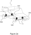
- Figure 2a is a schematic view illustrating the wheel suspension arrangement 1 when attached between the wheels 501, 502, 503, 504 of the front and rear wheel pairs of a vehicle 5.
- Figure 2b is a schematic section view illustrating the wheel suspension arrangement 1 when attached to a wheel 501, 502, 503, 504 of a vehicle 5.
- Each wheel 501, 502, 503, 504 has a wheel suspension arrangement 1 as described in relation to Figures 1a-c , such that the suspension stiffness of that particular wheel may be individually controlled.
- the wheel suspension arrangement 1 is oriented such that the control springs 106 bias the control members 103 in a direction towards a vehicle centreline that is parallel with the longitudinal extension of the vehicle 5.
- each wheel 501, 502, 503, 504 has an individual suspension stiffness control that is based on current driving conditions.
- none of the control springs 106 that hold the control members 103 will be loaded, causing the control members 103 to stay in the retracted position.
- the suspension springs 101 of each wheel 501, 502, 503, 504 will act as independent springs with no additional stiffening relative to each other.
Landscapes
- Engineering & Computer Science (AREA)
- Mechanical Engineering (AREA)
- General Engineering & Computer Science (AREA)
- Vehicle Body Suspensions (AREA)
- Springs (AREA)
Description
- The present invention relates to a wheel suspension arrangement having independent left and right sides.
- Conventional wheel suspension arrangements often comprise anti-roll bars designed to transfer the suspension stiffness of a wheel pair from the wheel suspension on one side of the vehicle to the wheel suspension on the opposite side of the vehicle (for example left front wheel to right front wheel). This causes less tilting or roll of the vehicle when performing a sharp turn. However, if the vehicle hits a bump with the wheels on one side, the anti-roll bar will also transfer stiffness to the opposite side, thus resulting in the bump being translated to the wheels on the opposite side as well. This makes hitting bumps with the vehicle less comfortable for its occupants. As such, a conventional anti-roll bar is a trade-off between turn comfort and single-side bump handling.
-
US 4,832,321 discloses a coil spring assembly for the suspension of a vehicle including a series of plates whose tapered edges protrude between the coils of the spring. The plates are mounted on bolts that are parallel to the longitudinal axis of the spring, the bolts being moveable toward or away from the longitudinal axis of the spring. The resulting movement of the plates toward or away from the spring causes a thicker or thinner zone of the tapered edge of the plate to be disposed between the spring coils, thereby changing the degree to which the plates stiffen the spring. - This allows a user to control the stiffness of the suspension of the vehicle by adjusting the position of the bolt. However, this adjustment needs to be done while the vehicle is stationary. As such, this assembly cannot be used to actively control the suspension stiffness in real-time based on current driving conditions.
-
DE 10 2017 205671 A1 discloses a wheel suspension arrangement according to the preamble ofclaim 1. It shows a spring arrangement, in particular in the form of a spring arrangement in a spring damper system, having a main spring and at least one secondary spring, wherein the total spring constant of the spring assembly is adjustable by the at least one secondary spring. -
DE 10 2007 007630 A1 discloses a spring strut, which has a spiral spring. A locking unit is provided in a radial direction on the spring strut, which is movable from a releasing position to a blocking position and vice versa. The spring strut force introduced into the spring strut in the blocking position is guided by the locking unit at an assigned elastomer element. -
JP 2008 230469 A - None of these assemblies can be used to actively control the suspension stiffness in real-time based on current driving conditions.
- It is an object of the present invention to alleviate at least some of the mentioned drawbacks of the prior art and to provide a wheel suspension arrangement that actively controls the suspension stiffness based on current driving conditions, and which combines turn comfort with single-side bump handling capabilities, thus eliminating the need for a conventional anti-roll bar. This and other objects, which will become apparent in the following, are accomplished by a wheel suspension arrangement as defined in the accompanying independent claim.
- The term exemplary should in this application be understood as serving as an example, instance or illustration.
- The invention is based on the realization that by decoupling the conventional anti-roll bar into two separate and independent turn-handling functions, the drawbacks of stiffness transferring when single-sidedly hitting bumps can be avoided. In the present invention, each wheel in a wheel pair is provided with a wheel suspension having its own integrated anti-roll function. This is beneficial, as such a wheel suspension arrangement allows turn comfort to be combined with single-side bump handling.
- The present invention is furthermore based on the realisation that this may be achieved by connecting the suspension spring of the wheel suspension arrangement to a support member having horizontally extending slots in which spring-loaded rods or control members are adapted to slide when the vehicle is turning. The springs connected to the control members have different spring constants, such that the sharper the vehicle is turning, the more control members will engage in the suspension spring, thereby making it stiffer. The suspension may, in addition to a suspension spring, have additional components such as a shock absorber and/or an additional spring for increased travel comfort.
- The present invention is furthermore based on the realisation that providing such a wheel suspension arrangement allows for increased comfort when driving sideways in a steep slope. In this case, the control members are subjected to a gravitational force that has a component in a direction that is parallel with their sliding direction. This causes a number of the control members to engage in the suspension spring, thus causing it to stiffen and making the vehicle less tilted during those situations.
- Finally, the wheel suspension arrangement of the present invention could also be implemented in the vehicle's driving direction, stiffening the front suspension when braking or driving downhill and stiffening the rear suspension when accelerating or driving uphill.
- According to the first aspect of the present invention, a wheel suspension arrangement is provided. The wheel suspension arrangement comprises a suspension spring, and a plurality of control members arranged to control a stiffness of said suspension spring. Each one of the control members is displaceable relative to said suspension spring between a retracted position, in which the control member does not interfere with an operation of the suspension spring, and an advanced position, in which it interferes with the operation of the suspension spring in a way that the stiffness of said suspension spring is increased. The wheel suspension arrangement further comprises a biasing means configured to bias each one of said plurality of control members towards said retracted position. The biasing means comprises a plurality of control springs, wherein each one of said plurality of control members is coupled to a respective control spring.
- The control members are arranged to affect the suspension spring at spaced locations in a longitudinal axis of the suspension spring. Additionally, the wheel suspension arrangement is configured for providing stepwise stiffening of the suspension spring as a function of the magnitude of the centrifugal force resulting from a sharp turn or a rapid acceleration or deceleration by arranging at least two of the control springs with different stiffnesses.
- Having a wheel suspension arrangement as described above allows for individual control of the stiffness of either wheel. For example, the wheel suspension arrangement of the present invention may be provided in connection with either wheel, a single wheel pair of a vehicle, or for all wheels of a vehicle. Thus, certain driving situations and conditions causes the stiffness of the wheel suspension arrangement to increase, while other driving situations or conditions do not cause the stiffness of the suspension spring to increase.
- The provision of a plurality of control springs enables individual biasing of the control members towards the retracted position, such that they may move between retracted and advanced position independently of each other.
- Having the control members be arranged to affect the suspension spring at spaced locations in a longitudinal axis of the suspension spring allows for step-wise stiffening of the suspension spring, by engaging the suspension spring with one control member at a time.
- By having the control springs for the plurality of control members be provided at different spring constants or stiffnesses, it is possible to control at which centrifugal force each individual control member moves from the retracted position to the advanced position. Thus, step-wise stiffening of the suspension spring as a function of the magnitude of the centrifugal force resulting from a sharp turn or a rapid acceleration or deceleration is enabled. In other words, the sharper a vehicle provided with the wheel suspension arrangement of the present invention turns, the more the suspension spring on one side of the vehicle is stiffened.
- According to one exemplary embodiment of the present invention, each one of said plurality of control members is displaceable relative to said suspension spring between a retracted position, in which each one of said plurality of control members does not restrict the compression of the suspension spring, and an advanced position, in which it restricts the compression of the suspension spring in a way that the effective stiffness of said suspension spring is increased.
- According to one exemplary embodiment of the present invention, each one of said plurality of control members, in said advanced position, decreases an effective length of the suspension spring.
- The effective length of the suspension spring is to be understood as being the distance the suspension spring may be elastically compressed as a result of axial forces acting upon the spring from the vehicle body and the wheel.
- As the spring constant of a spring is inversely proportional to its length, decreasing the effective length of the spring increases the effective spring constant of that spring. As such, the control members increase the effective spring constant of the suspension spring when in the advanced position. By having the control members for the wheels on only one side of the vehicle move to the advanced position when a stiff spring is required, such as in a sharp turn, a single-sided spring stiffening is achieved.
- According to one exemplary embodiment of the present invention, each one of said plurality of control members intersects said suspension spring in said advanced position. This decreases the effective length of the spring, thus increasing the effective spring constant as described above. The intersection may be partial, in that the control members intersect one half of the spring coil, or complete, in that the control members intersect the entire spring coil, i.e. extending through it.
- According to one exemplary embodiment of the present invention, each one of said plurality of control members is displaceable in a direction transverse to a longitudinal axis of the suspension spring.
- According to one exemplary embodiment of the present invention, said suspension spring is a coil spring and each one of said plurality of control members is arranged to protrude between the coils of the spring in said advanced position. By protruding through the coils of the spring, at least one control member fixes a portion of the coil in relation to the vehicle body. This decreases the effective length of the coil, thus increasing its stiffness.
- According to one exemplary embodiment of the present invention, the wheel suspension arrangement comprises a support member arranged to support each one of said plurality of control members in the advanced position. In one exemplary embodiment, the support member is arranged to support each one of said plurality of control members in both the advanced and the retracted position. The support member may either be fixedly attached to the vehicle body, or it may be connected thereto by means of a support spring. The support spring increases driving comfort by allowing for a smoother ride compared to suspension arrangements that are fixedly attached to the vehicle body.
- According to one exemplary embodiment of the present invention, said support member comprises at least one slot, inside which each one of said plurality of control members is arranged and along which each one of the plurality of said control members is displaceable.
- This slot may alternatively be referred to as a track or a groove, inside of which the control member is slidably arranged. The position of the slots in relation to the suspension spring is such that each one of said plurality of control members when moving from a retracted position to an advanced position, enters the suspension spring between its coils.
- According to one exemplary embodiment of the present invention, the plurality of control members are arranged in parallel with each other. The control members may for example be arranged in the same direction as the centrifugal force that results from when a vehicle onto which the wheel suspension arrangement is connected takes a sharp turn, or brakes or accelerates rapidly. The wheel suspension arrangement, when attached between a wheel and a vehicle body, may be oriented such that the control springs bias the control members in a direction towards a vehicle centreline that is perpendicular with the longitudinal extension of the vehicle. This allows inertial forces resulting from the vehicle accelerating or decelerating to cause a number of the control members to slide into engagement with the suspension springs on the rear or front wheel pair, respectively.
- According to one exemplary embodiment of the present invention, the wheel suspension arrangement has a wheel connecting side and a vehicle body connecting side, wherein control members located closer to the wheel connecting side are more strongly biased towards the retracted position than control members located closer to the vehicle connecting side.
- According to one exemplary embodiment of the present invention, the wheel suspension arrangement has a wheel connecting side and a vehicle body connecting side, wherein the stiffness of the control springs increases from the vehicle body connecting side to the wheel connecting side.
- According to one exemplary embodiment of the present invention, each one of said plurality of control members is displaceable along a direction that is perpendicular to a longitudinal axis of the suspension spring.
- According to one exemplary embodiment of the present invention, each one of said plurality of control members is slidably displaceable when the wheel suspension arrangement is subjected to a force that is perpendicular to a longitudinal axis of the suspension spring. The control members and the control springs are configured such that the control members move from the retracted position to the advanced position once the control members are subjected to a force exceeding a predetermined threshold value. This predetermined threshold value may differ from one control member to the others, with the threshold increasing from the control member located closest to the vehicle body connecting side to the control member located closest to the wheel connecting side.
- According to a non-claimed aspect of the present disclosure, a vehicle having a wheel suspension arrangement according to the first aspect of the present invention is provided. It should be understood that the embodiments of the first aspect of the invention are equally applicable to the non-claimed aspect of the disclosure.
- Generally, all terms used in the description are to be interpreted according to their ordinary meaning in the technical field, unless explicitly defined otherwise herein. All references to "a/an/the [element, device, component, means, step, etc.]" are to be interpreted openly as referring to at least one instance of said element, device, component, means, step, etc., unless explicitly stated otherwise.
- Features and advantages of the present invention will now be further clarified and described in more detail, with reference to the appended drawings showing different embodiments of a wheel suspension arrangement according to the invention and a vehicle provided with such an arrangement.
-
Figure 1a is a schematic view of the wheel suspension arrangement of the first aspect of the present invention, -
Figure 1b is a schematic view of the wheel suspension arrangement ofFig. 1a , when a number of the control members have moved to the advanced position and the suspension spring has been partially compressed, -
Figure 1c is a schematic view of the wheel suspension arrangement ofFig. 1a , when even more of the control members have moved to the advanced position, thus further stiffening the suspension spring, and -
Figure 2a is a schematic view illustrating the wheel suspension arrangement when attached to the front and rear wheel pairs of a vehicle, -
Figure 2b is a schematic section view illustrating the wheel suspension arrangement when attached to a wheel of a vehicle. - In the following detailed description, some embodiments of the present invention will be described. However, it is to be understood that features of the different embodiments are exchangeable between the embodiments and may be combined in different ways, unless anything else is specifically indicated. Even though in the following description, numerous specific details are set forth to provide a more thorough understanding of the present invention, it will be apparent to one skilled in the art that the present invention may be practiced without these specific details. In other instances, well known constructions or functions are not described in detail, so as not to obscure the present invention.
-
Figure 1a is a schematic view of thewheel suspension arrangement 1 of the first aspect of the present invention. Thewheel suspension arrangement 1 comprises adamper 102 and asuspension spring 101 connected to thedamper 102. Thedamper 102 has awheel connecting side 111 arranged to be connected to a wheel of a vehicle, and a vehiclebody connecting side 113 arranged to be connected to a vehicle body. Thesuspension spring 101 extends between the twosides damper 102 and exerts a force that counteracts compression of thedamper 102. Thesuspension spring 101 is a coil spring, the ends of which abut correspondingabutment portions 104 on eachend damper 102. - The
wheel suspension arrangement 1 further comprisescontrol members 103 or control rods slidably arranged so that they may move between a retracted position, in which they do not interfere with the compression or elongation of thesuspension spring 101, and an advanced position, in which thecontrol members 103 protrude between the coils 101' of thesuspension spring 101. This causes theeffective length 901 of thesuspension spring 101 to decrease, thus increasing its stiffness. As such, the stiffness of thesuspension spring 101 may be controlled by selectively engaging thesuspension spring 101 with a number ofcontrol members 103, that number being determined by the need for suspension stiffness, i.e. the current driving conditions. InFig. 1a however, allcontrol members 103 are in the retracted position. - The
control members 103 are arranged inside asupport member 107 or housing that is arranged adjacent to thesuspension spring 101. Thesupport member 107 comprises a plurality ofslots 109 or tracks inside of which thecontrol members 103 are slidably arranged. In the illustrated embodiment, thesupport member 107 is provided on both sides of thesuspension spring 101, such that when thecontrol members 103 protrude through the coils 101' of thesuspension spring 101, they may be received by theslots 109 on portion of thesupport member 107 on the opposite side of thesuspension spring 101. This increases the stability of thecontrol members 103 as they lock the coils 101' of thesuspension spring 101 in place. - The
support member 107 comprises asupport spring 108 that may be used, in addition to the vehiclebody connecting side 113 of thedamper 102, to attach thewheel suspension arrangement 1 to a vehicle. Thesupport spring 108 further increases driving comfort by taking up a portion of the shocks and vibrations from the road and smoothens out the "steps" that may be felt in the vehicle when each control member is being engaged in the suspension spring. - The
slots 109 are arranged to guide thecontrol members 103 in a direction between the retracted position and the advanced position. In the illustrated embodiment, this direction is perpendicular to the longitudinal axis of thesuspension spring 101. However, variations to this angle are conceivable depending on for example spring geometry or the relative positions of thecontrol members 103 and thesuspension spring 101. - The
control members 103 are provided inindividual slots 109 inside thesupport member 107, at locations spaced apart along a direction that is parallel to a longitudinal axis of thesuspension spring 101. Thus, eachcontrol member 103 is arranged to engage different portions of thesuspension spring 101 than theother control members 103. - Furthermore, the
wheel suspension arrangement 1 comprises biasing means 105 that are configured to bias thecontrol members 103 towards the retracted position. The biasing means 105 comprises a plurality of control springs 106, and each one of thecontrol members 103 is coupled to arespective control spring 106. This allows for individual control of the biasing strength of thecontrol members 103, by providing control springs 106 with varying stiffness fordifferent control members 103. The control springs 106 extend between one end of thecontrol members 103 and thesupport member 107, such that thecontrol members 103 are connected to thesupport member 107 by the control springs 106. In the illustrated embodiment, thecontrol spring 106 closest to thewheel connecting side 111 is stiffer than thecontrol spring 106 located directly adjacent to it, towards the vehiclebody connecting side 113 of thewheel suspension arrangement 1. This continues for eachcontrol spring 106, with decreasing stiffness for each step towards the vehiclebody connecting side 113. Thus, thecontrol members 103 located closer to thewheel connecting side 111 are more strongly biased towards the retracted position thancontrol members 103 located closer to thevehicle connecting side 113. -
Figure 1b is a schematic view of thewheel suspension arrangement 1 ofFig. 1a . Here, a number of thecontrol members 103 have moved to the advanced position and thesuspension spring 101 has been partially compressed. This could for example be an illustration of what thewheel suspension arrangement 1 may look like when a vehicle to which thewheel suspension arrangement 1 is attached takes a moderately sharp turn. The centrifugal force experienced by thecontrol members 103 is sufficient to overcome the bias of the threecontrol springs 106 located closest to the vehiclebody connecting side 113, but not strong enough to overcome the remaining control springs' 106 biasing force. Thus, the threecontrol members 103 located closest to the vehiclebody connecting side 113 are displaced to the advanced position by means of the centrifugal force, such that they intersect thesuspension spring 101. This shortens theeffective length 901 of thesuspension spring 101, thus increasing its effective spring constant. -
Figure 1c is, likeFig. 1b , a schematic view of thewheel suspension arrangement 1 ofFig. 1a . Here, even more of thecontrol members 103 have moved to the advanced position than inFig. 1b , thus further decreasing theeffective length 901 of thesuspension spring 101. This could for example be an illustration of what thewheel suspension arrangement 1 may look like when a vehicle to which thewheel suspension arrangement 1 is attached takes a sharp turn. -
Figure 2a is a schematic view illustrating thewheel suspension arrangement 1 when attached between thewheels vehicle 5.Figure 2b is a schematic section view illustrating thewheel suspension arrangement 1 when attached to awheel vehicle 5. Eachwheel wheel suspension arrangement 1 as described in relation toFigures 1a-c , such that the suspension stiffness of that particular wheel may be individually controlled. When attached to awheel vehicle 5, thewheel suspension arrangement 1 is oriented such that the control springs 106 bias thecontrol members 103 in a direction towards a vehicle centreline that is parallel with the longitudinal extension of thevehicle 5. This allows a centrifugal force resulting from thevehicle 5 taking a sharp turn to cause a number of thecontrol members 103 of thewheel suspension arrangement 1 located on the outer side of the turn to slide into engagement with thesuspension spring 101. In case of a sharp right turn ofvehicle 5, this stiffens thesuspension spring 101 on thewheels wheels vehicle 5 takes a sharp right turn, a number of thecontrol members 103 of the front left and rearleft wheel control spring 106 bias, slide to engage the suspension springs 101 of thosewheels vehicle 5. Thecontrol members 103 of thewheel suspension arrangements 1 provided at the front right and rearright wheels suspension spring 101. The opposite will happen if thevehicle 5 makes a sharp left turn. - Using the
wheel suspensions arrangement 1 of the present invention, and attaching it to avehicle 5 as described above, results in that eachwheel control members 103 of thewheel suspension arrangement 1 of eachwheel control members 103 will be loaded, causing thecontrol members 103 to stay in the retracted position. This means that the suspension springs 101 of eachwheel - The person skilled in the art realizes that the present invention by no means is limited to the embodiments described above. The features of the described embodiments may be combined in different ways, and many modifications and variations are possible within the scope of the appended claims. In the claims, any reference signs placed between parentheses shall not be construed as limiting to the claim. The word "comprising" does not exclude the presence of other elements or steps than those listed in the claim. The word "a" or "an" preceding an element does not exclude the presence of a plurality of such elements.
Claims (12)
- A wheel suspension arrangement (1) comprising:a suspension spring (101),a plurality of control members (103) arranged to control a stiffness of said suspension spring (101),
wherein each one of the plurality of control members (103) is displaceable relative to said suspension spring (101) between a retracted position, in which the control member (103) does not interfere with an operation of the suspension spring (101), and an advanced position, in which it interferes with the operation of the suspension spring (101) in a way that the stiffness of said suspension spring (101) is increased, anda biasing means (105) configured to bias each one of said plurality of control members (103) towards said retracted position, wherein said biasing means (105) comprising a plurality of control springs (106),wherein each one of said plurality of control members (103) is coupled to a respective control spring (106), and wherein said control members (103) are arranged to affect the suspension spring (101) at spaced locations in a longitudinal axis of the suspension spring (101),
characterised in thatthe wheel suspension arrangement (1) is configured for providing stepwise stiffening of the suspension spring as a function of the magnitude of the centrifugal force resulting from a sharp turn or a rapid acceleration or deceleration by arranging at least two of the control springs (106) with different stiffnesses. - Wheel suspension arrangement (1) according to claim 1, wherein each one of said plurality of control members (103), in said advanced position, decreases an effective length (901) of the suspension spring (101).
- Wheel suspension arrangement (1) according to any one of the preceding claims, wherein each one of said plurality of control members (103) intersects said suspension spring (101) in said advanced position.
- Wheel suspension arrangement (1) according to any one of the preceding claims, wherein each one of said plurality of control members (103) is displaceable in a direction transverse to a longitudinal axis of the suspension spring (101).
- Wheel suspension arrangement (1) according to any one of the preceding claims, wherein said suspension spring (101) is a coil spring and wherein each one of said plurality of control members (103) is arranged to protrude between the coils (101') of the coil spring in said advanced position.
- Wheel suspension arrangement (1) according to any one of the preceding claims, wherein the wheel suspension arrangement (1) comprises a support member (107) arranged to support each one of said plurality of control members (103) in the advanced position.
- Wheel suspension arrangement (1) according to claim 6, wherein said support member (107) comprises at least one slot (109), inside which each one of said plurality of control members (103) is arranged and along which said control member (103) is displaceable.
- Wheel suspension arrangement (1) according to any one of the preceding claims, wherein the plurality of control members (103) are arranged in parallel with each other.
- Wheel suspension arrangement (1) according to any one of the preceding claims, having a wheel connecting side (111) and a vehicle body connecting side (113), wherein the control members of said plurality of control members (103) located closer to the wheel connecting side (111) are more strongly biased towards the retracted position than the control members of said plurality of control members (103) located closer to the vehicle connecting side (113).
- Wheel suspension arrangement (1) according to any one of the preceding claims 1 - 8, having a wheel connecting side (111) and a vehicle body connecting side (113), wherein the stiffness of the control springs (106) increases from the vehicle body connecting side (113) to the wheel connecting side (111).
- Wheel suspension arrangement (1) according to any one of the preceding claims, wherein each one of said plurality of control members (103) is displaceable along a direction that is perpendicular to a longitudinal axis of the suspension spring (101).
- Wheel suspension arrangement (1) according to any one of the preceding claims, wherein each one of said plurality of control members (103) is slidably displaceable when the wheel suspension arrangement (1) is subjected to a force that is perpendicular to a longitudinal axis of the suspension spring (101).
Priority Applications (4)
| Application Number | Priority Date | Filing Date | Title |
|---|---|---|---|
| EP19170755.3A EP3730322B1 (en) | 2019-04-24 | 2019-04-24 | Wheel suspension arrangement |
| CN202080029023.9A CN113710511B (en) | 2019-04-24 | 2020-03-18 | Wheel suspension assembly |
| PCT/CN2020/079983 WO2020215929A1 (en) | 2019-04-24 | 2020-03-18 | Wheel suspension arrangement |
| US17/503,301 US11878561B2 (en) | 2019-04-24 | 2021-10-16 | Wheel suspension arrangement |
Applications Claiming Priority (1)
| Application Number | Priority Date | Filing Date | Title |
|---|---|---|---|
| EP19170755.3A EP3730322B1 (en) | 2019-04-24 | 2019-04-24 | Wheel suspension arrangement |
Publications (2)
| Publication Number | Publication Date |
|---|---|
| EP3730322A1 EP3730322A1 (en) | 2020-10-28 |
| EP3730322B1 true EP3730322B1 (en) | 2022-12-14 |
Family
ID=66251629
Family Applications (1)
| Application Number | Title | Priority Date | Filing Date |
|---|---|---|---|
| EP19170755.3A Active EP3730322B1 (en) | 2019-04-24 | 2019-04-24 | Wheel suspension arrangement |
Country Status (4)
| Country | Link |
|---|---|
| US (1) | US11878561B2 (en) |
| EP (1) | EP3730322B1 (en) |
| CN (1) | CN113710511B (en) |
| WO (1) | WO2020215929A1 (en) |
Families Citing this family (1)
| Publication number | Priority date | Publication date | Assignee | Title |
|---|---|---|---|---|
| CN112709345B (en) * | 2020-12-29 | 2022-01-11 | 重庆工程职业技术学院 | Assembled building with shock attenuation heat insulation function |
Family Cites Families (16)
| Publication number | Priority date | Publication date | Assignee | Title |
|---|---|---|---|---|
| GB1037838A (en) * | 1964-07-15 | 1966-08-03 | Salter & Co Ltd G | Compensator device for improving the extension characteristics of coil extension springs |
| DE2822105C2 (en) * | 1978-05-20 | 1982-08-05 | Bayerische Motoren Werke Ag, 8000 Muenchen | Device for influencing the spring travel and the spring characteristic of a resilient wheel suspension of vehicles |
| US4832321A (en) | 1988-07-11 | 1989-05-23 | The United States Of America As Represented By The Secretary Of The Army | Variable stiffness spring suspension |
| CN1190606C (en) * | 2001-02-06 | 2005-02-23 | 周政明 | Adjustable Coil Spring Housing Assembly |
| US7097014B2 (en) * | 2004-06-04 | 2006-08-29 | Tan-Cheng Huang | Shock absorber |
| CN2844566Y (en) * | 2005-07-07 | 2006-12-06 | 侯玉峰 | Automobile damping spring rigidity controlling device |
| DE102007007630A1 (en) * | 2007-02-16 | 2008-08-21 | Bayerische Motoren Werke Aktiengesellschaft | Vehicle, especially motorcycle, with a strut with adjustable spring rate |
| JP4881772B2 (en) * | 2007-03-22 | 2012-02-22 | 本田技研工業株式会社 | Suspension structure |
| DE102012003199B4 (en) * | 2012-02-17 | 2015-05-21 | Audi Ag | Spring device for an active suspension of motor vehicles |
| CN103256331B (en) * | 2012-09-13 | 2015-03-11 | 广东正美家具科技有限公司 | Pressure spring adjustable in elastic rigidity |
| DE102013205335A1 (en) * | 2013-03-26 | 2014-10-02 | Ford Global Technologies, Llc | Independent suspension for the non-driven wheels of a vehicle |
| DE102015207316A1 (en) * | 2015-04-22 | 2016-10-27 | Schaeffler Technologies AG & Co. KG | System for adjusting the spring stiffness of a suspension spring |
| CN106151335A (en) * | 2015-04-28 | 2016-11-23 | 上海交通大学 | There is the elastic stiffness tunable arrangement of regulating part |
| DE102017205671B4 (en) * | 2017-04-04 | 2025-05-22 | Bayerische Motoren Werke Aktiengesellschaft | Spring arrangement with variable spring constant |
| CN107420646B (en) * | 2017-07-03 | 2023-04-28 | 中国大唐集团科学技术研究院有限公司西北分公司 | Adjustable pipeline vibration multidirectional buffer device |
| DE102019218862B4 (en) * | 2019-01-24 | 2021-06-02 | Ford Global Technologies, Llc | Active suspension by changing the spring characteristic with spring lock actuation |
-
2019
- 2019-04-24 EP EP19170755.3A patent/EP3730322B1/en active Active
-
2020
- 2020-03-18 WO PCT/CN2020/079983 patent/WO2020215929A1/en not_active Ceased
- 2020-03-18 CN CN202080029023.9A patent/CN113710511B/en active Active
-
2021
- 2021-10-16 US US17/503,301 patent/US11878561B2/en active Active
Also Published As
| Publication number | Publication date |
|---|---|
| WO2020215929A1 (en) | 2020-10-29 |
| CN113710511B (en) | 2024-05-03 |
| EP3730322A1 (en) | 2020-10-28 |
| US11878561B2 (en) | 2024-01-23 |
| US20220032712A1 (en) | 2022-02-03 |
| CN113710511A (en) | 2021-11-26 |
Similar Documents
| Publication | Publication Date | Title |
|---|---|---|
| US8398092B2 (en) | Active roll control system for vehicle | |
| KR100386366B1 (en) | Suspension system | |
| US8632078B2 (en) | Vehicle with a leaf spring element for the spring suspension of the vehicle | |
| EP1238833A1 (en) | Suspension system | |
| JP2018514440A (en) | Combined spring compensation suspension system | |
| WO2011149579A1 (en) | Preloaded dual-spring assembly | |
| JP6091790B2 (en) | Active control suspension | |
| US20150145187A1 (en) | Leaf spring assembly | |
| EP4127508A1 (en) | Damper assembly | |
| US8757333B2 (en) | Vibration damping method | |
| US8485542B1 (en) | Suspension system for a vehicle | |
| US20030098565A1 (en) | Leaf spring rear axle vehicle suspension | |
| WO2017034866A1 (en) | Elastomer spring for vehicle | |
| US11878561B2 (en) | Wheel suspension arrangement | |
| CN100540342C (en) | Independent Suspension of Shuangrui Automobile | |
| EP1734277B1 (en) | Spring device for a motor vehicle, having a compression spring with a variable spring characteristic | |
| KR102901088B1 (en) | Pendulum rocker damper with a rotating axis | |
| EP1157864B1 (en) | Torsion bar with multiple arm adjusters for a vehicle suspension system | |
| KR100320498B1 (en) | Vehicle suspension system | |
| CN216300703U (en) | Vehicle and rear suspension assembly for vehicle | |
| US5005855A (en) | Insulator device for strut type suspension system of automobile | |
| CN114667226B (en) | Anti-roll wheel suspension system for vehicle, method for preventing vehicle roll by anti-roll wheel suspension system | |
| ES3032465T3 (en) | A multi-stage spring system suitable for use in vehicles | |
| KR100293670B1 (en) | Front wheel suspension of vehicle | |
| US20050236795A1 (en) | Rear vehicle axle |
Legal Events
| Date | Code | Title | Description |
|---|---|---|---|
| PUAI | Public reference made under article 153(3) epc to a published international application that has entered the european phase |
Free format text: ORIGINAL CODE: 0009012 |
|
| STAA | Information on the status of an ep patent application or granted ep patent |
Free format text: STATUS: REQUEST FOR EXAMINATION WAS MADE |
|
| 17P | Request for examination filed |
Effective date: 20190424 |
|
| AK | Designated contracting states |
Kind code of ref document: A1 Designated state(s): AL AT BE BG CH CY CZ DE DK EE ES FI FR GB GR HR HU IE IS IT LI LT LU LV MC MK MT NL NO PL PT RO RS SE SI SK SM TR |
|
| AX | Request for extension of the european patent |
Extension state: BA ME |
|
| STAA | Information on the status of an ep patent application or granted ep patent |
Free format text: STATUS: EXAMINATION IS IN PROGRESS |
|
| 17Q | First examination report despatched |
Effective date: 20210621 |
|
| GRAP | Despatch of communication of intention to grant a patent |
Free format text: ORIGINAL CODE: EPIDOSNIGR1 |
|
| STAA | Information on the status of an ep patent application or granted ep patent |
Free format text: STATUS: GRANT OF PATENT IS INTENDED |
|
| INTG | Intention to grant announced |
Effective date: 20220707 |
|
| GRAS | Grant fee paid |
Free format text: ORIGINAL CODE: EPIDOSNIGR3 |
|
| GRAA | (expected) grant |
Free format text: ORIGINAL CODE: 0009210 |
|
| STAA | Information on the status of an ep patent application or granted ep patent |
Free format text: STATUS: THE PATENT HAS BEEN GRANTED |
|
| AK | Designated contracting states |
Kind code of ref document: B1 Designated state(s): AL AT BE BG CH CY CZ DE DK EE ES FI FR GB GR HR HU IE IS IT LI LT LU LV MC MK MT NL NO PL PT RO RS SE SI SK SM TR |
|
| REG | Reference to a national code |
Ref country code: GB Ref legal event code: FG4D |
|
| REG | Reference to a national code |
Ref country code: CH Ref legal event code: EP |
|
| REG | Reference to a national code |
Ref country code: DE Ref legal event code: R096 Ref document number: 602019023062 Country of ref document: DE |
|
| REG | Reference to a national code |
Ref country code: IE Ref legal event code: FG4D |
|
| REG | Reference to a national code |
Ref country code: AT Ref legal event code: REF Ref document number: 1537463 Country of ref document: AT Kind code of ref document: T Effective date: 20230115 |
|
| REG | Reference to a national code |
Ref country code: LT Ref legal event code: MG9D |
|
| REG | Reference to a national code |
Ref country code: NL Ref legal event code: MP Effective date: 20221214 |
|
| PG25 | Lapsed in a contracting state [announced via postgrant information from national office to epo] |
Ref country code: SE Free format text: LAPSE BECAUSE OF FAILURE TO SUBMIT A TRANSLATION OF THE DESCRIPTION OR TO PAY THE FEE WITHIN THE PRESCRIBED TIME-LIMIT Effective date: 20221214 Ref country code: NO Free format text: LAPSE BECAUSE OF FAILURE TO SUBMIT A TRANSLATION OF THE DESCRIPTION OR TO PAY THE FEE WITHIN THE PRESCRIBED TIME-LIMIT Effective date: 20230314 Ref country code: LT Free format text: LAPSE BECAUSE OF FAILURE TO SUBMIT A TRANSLATION OF THE DESCRIPTION OR TO PAY THE FEE WITHIN THE PRESCRIBED TIME-LIMIT Effective date: 20221214 Ref country code: FI Free format text: LAPSE BECAUSE OF FAILURE TO SUBMIT A TRANSLATION OF THE DESCRIPTION OR TO PAY THE FEE WITHIN THE PRESCRIBED TIME-LIMIT Effective date: 20221214 |
|
| REG | Reference to a national code |
Ref country code: AT Ref legal event code: MK05 Ref document number: 1537463 Country of ref document: AT Kind code of ref document: T Effective date: 20221214 |
|
| PG25 | Lapsed in a contracting state [announced via postgrant information from national office to epo] |
Ref country code: RS Free format text: LAPSE BECAUSE OF FAILURE TO SUBMIT A TRANSLATION OF THE DESCRIPTION OR TO PAY THE FEE WITHIN THE PRESCRIBED TIME-LIMIT Effective date: 20221214 Ref country code: LV Free format text: LAPSE BECAUSE OF FAILURE TO SUBMIT A TRANSLATION OF THE DESCRIPTION OR TO PAY THE FEE WITHIN THE PRESCRIBED TIME-LIMIT Effective date: 20221214 Ref country code: HR Free format text: LAPSE BECAUSE OF FAILURE TO SUBMIT A TRANSLATION OF THE DESCRIPTION OR TO PAY THE FEE WITHIN THE PRESCRIBED TIME-LIMIT Effective date: 20221214 |
|
| PG25 | Lapsed in a contracting state [announced via postgrant information from national office to epo] |
Ref country code: NL Free format text: LAPSE BECAUSE OF FAILURE TO SUBMIT A TRANSLATION OF THE DESCRIPTION OR TO PAY THE FEE WITHIN THE PRESCRIBED TIME-LIMIT Effective date: 20221214 |
|
| PG25 | Lapsed in a contracting state [announced via postgrant information from national office to epo] |
Ref country code: SM Free format text: LAPSE BECAUSE OF FAILURE TO SUBMIT A TRANSLATION OF THE DESCRIPTION OR TO PAY THE FEE WITHIN THE PRESCRIBED TIME-LIMIT Effective date: 20221214 Ref country code: RO Free format text: LAPSE BECAUSE OF FAILURE TO SUBMIT A TRANSLATION OF THE DESCRIPTION OR TO PAY THE FEE WITHIN THE PRESCRIBED TIME-LIMIT Effective date: 20221214 Ref country code: PT Free format text: LAPSE BECAUSE OF FAILURE TO SUBMIT A TRANSLATION OF THE DESCRIPTION OR TO PAY THE FEE WITHIN THE PRESCRIBED TIME-LIMIT Effective date: 20230414 Ref country code: ES Free format text: LAPSE BECAUSE OF FAILURE TO SUBMIT A TRANSLATION OF THE DESCRIPTION OR TO PAY THE FEE WITHIN THE PRESCRIBED TIME-LIMIT Effective date: 20221214 Ref country code: EE Free format text: LAPSE BECAUSE OF FAILURE TO SUBMIT A TRANSLATION OF THE DESCRIPTION OR TO PAY THE FEE WITHIN THE PRESCRIBED TIME-LIMIT Effective date: 20221214 Ref country code: CZ Free format text: LAPSE BECAUSE OF FAILURE TO SUBMIT A TRANSLATION OF THE DESCRIPTION OR TO PAY THE FEE WITHIN THE PRESCRIBED TIME-LIMIT Effective date: 20221214 Ref country code: AT Free format text: LAPSE BECAUSE OF FAILURE TO SUBMIT A TRANSLATION OF THE DESCRIPTION OR TO PAY THE FEE WITHIN THE PRESCRIBED TIME-LIMIT Effective date: 20221214 |
|
| PG25 | Lapsed in a contracting state [announced via postgrant information from national office to epo] |
Ref country code: SK Free format text: LAPSE BECAUSE OF FAILURE TO SUBMIT A TRANSLATION OF THE DESCRIPTION OR TO PAY THE FEE WITHIN THE PRESCRIBED TIME-LIMIT Effective date: 20221214 Ref country code: PL Free format text: LAPSE BECAUSE OF FAILURE TO SUBMIT A TRANSLATION OF THE DESCRIPTION OR TO PAY THE FEE WITHIN THE PRESCRIBED TIME-LIMIT Effective date: 20221214 Ref country code: IS Free format text: LAPSE BECAUSE OF FAILURE TO SUBMIT A TRANSLATION OF THE DESCRIPTION OR TO PAY THE FEE WITHIN THE PRESCRIBED TIME-LIMIT Effective date: 20230414 Ref country code: AL Free format text: LAPSE BECAUSE OF FAILURE TO SUBMIT A TRANSLATION OF THE DESCRIPTION OR TO PAY THE FEE WITHIN THE PRESCRIBED TIME-LIMIT Effective date: 20221214 |
|
| REG | Reference to a national code |
Ref country code: DE Ref legal event code: R097 Ref document number: 602019023062 Country of ref document: DE |
|
| PLBE | No opposition filed within time limit |
Free format text: ORIGINAL CODE: 0009261 |
|
| STAA | Information on the status of an ep patent application or granted ep patent |
Free format text: STATUS: NO OPPOSITION FILED WITHIN TIME LIMIT |
|
| PG25 | Lapsed in a contracting state [announced via postgrant information from national office to epo] |
Ref country code: DK Free format text: LAPSE BECAUSE OF FAILURE TO SUBMIT A TRANSLATION OF THE DESCRIPTION OR TO PAY THE FEE WITHIN THE PRESCRIBED TIME-LIMIT Effective date: 20221214 |
|
| 26N | No opposition filed |
Effective date: 20230915 |
|
| PG25 | Lapsed in a contracting state [announced via postgrant information from national office to epo] |
Ref country code: SI Free format text: LAPSE BECAUSE OF FAILURE TO SUBMIT A TRANSLATION OF THE DESCRIPTION OR TO PAY THE FEE WITHIN THE PRESCRIBED TIME-LIMIT Effective date: 20221214 |
|
| REG | Reference to a national code |
Ref country code: CH Ref legal event code: PL |
|
| PG25 | Lapsed in a contracting state [announced via postgrant information from national office to epo] |
Ref country code: LU Free format text: LAPSE BECAUSE OF NON-PAYMENT OF DUE FEES Effective date: 20230424 |
|
| REG | Reference to a national code |
Ref country code: BE Ref legal event code: MM Effective date: 20230430 |
|
| PG25 | Lapsed in a contracting state [announced via postgrant information from national office to epo] |
Ref country code: MC Free format text: LAPSE BECAUSE OF FAILURE TO SUBMIT A TRANSLATION OF THE DESCRIPTION OR TO PAY THE FEE WITHIN THE PRESCRIBED TIME-LIMIT Effective date: 20221214 |
|
| PG25 | Lapsed in a contracting state [announced via postgrant information from national office to epo] |
Ref country code: MC Free format text: LAPSE BECAUSE OF FAILURE TO SUBMIT A TRANSLATION OF THE DESCRIPTION OR TO PAY THE FEE WITHIN THE PRESCRIBED TIME-LIMIT Effective date: 20221214 Ref country code: LI Free format text: LAPSE BECAUSE OF NON-PAYMENT OF DUE FEES Effective date: 20230430 Ref country code: CH Free format text: LAPSE BECAUSE OF NON-PAYMENT OF DUE FEES Effective date: 20230430 |
|
| REG | Reference to a national code |
Ref country code: IE Ref legal event code: MM4A |
|
| PG25 | Lapsed in a contracting state [announced via postgrant information from national office to epo] |
Ref country code: BE Free format text: LAPSE BECAUSE OF NON-PAYMENT OF DUE FEES Effective date: 20230430 |
|
| PG25 | Lapsed in a contracting state [announced via postgrant information from national office to epo] |
Ref country code: IE Free format text: LAPSE BECAUSE OF NON-PAYMENT OF DUE FEES Effective date: 20230424 |
|
| PG25 | Lapsed in a contracting state [announced via postgrant information from national office to epo] |
Ref country code: IE Free format text: LAPSE BECAUSE OF NON-PAYMENT OF DUE FEES Effective date: 20230424 |
|
| PG25 | Lapsed in a contracting state [announced via postgrant information from national office to epo] |
Ref country code: IT Free format text: LAPSE BECAUSE OF FAILURE TO SUBMIT A TRANSLATION OF THE DESCRIPTION OR TO PAY THE FEE WITHIN THE PRESCRIBED TIME-LIMIT Effective date: 20221214 |
|
| PG25 | Lapsed in a contracting state [announced via postgrant information from national office to epo] |
Ref country code: BG Free format text: LAPSE BECAUSE OF FAILURE TO SUBMIT A TRANSLATION OF THE DESCRIPTION OR TO PAY THE FEE WITHIN THE PRESCRIBED TIME-LIMIT Effective date: 20221214 |
|
| PG25 | Lapsed in a contracting state [announced via postgrant information from national office to epo] |
Ref country code: BG Free format text: LAPSE BECAUSE OF FAILURE TO SUBMIT A TRANSLATION OF THE DESCRIPTION OR TO PAY THE FEE WITHIN THE PRESCRIBED TIME-LIMIT Effective date: 20221214 |
|
| PGFP | Annual fee paid to national office [announced via postgrant information from national office to epo] |
Ref country code: DE Payment date: 20250417 Year of fee payment: 7 |
|
| PG25 | Lapsed in a contracting state [announced via postgrant information from national office to epo] |
Ref country code: CY Free format text: LAPSE BECAUSE OF FAILURE TO SUBMIT A TRANSLATION OF THE DESCRIPTION OR TO PAY THE FEE WITHIN THE PRESCRIBED TIME-LIMIT; INVALID AB INITIO Effective date: 20190424 |
|
| PG25 | Lapsed in a contracting state [announced via postgrant information from national office to epo] |
Ref country code: HU Free format text: LAPSE BECAUSE OF FAILURE TO SUBMIT A TRANSLATION OF THE DESCRIPTION OR TO PAY THE FEE WITHIN THE PRESCRIBED TIME-LIMIT; INVALID AB INITIO Effective date: 20190424 |
|
| PG25 | Lapsed in a contracting state [announced via postgrant information from national office to epo] |
Ref country code: GR Free format text: LAPSE BECAUSE OF FAILURE TO SUBMIT A TRANSLATION OF THE DESCRIPTION OR TO PAY THE FEE WITHIN THE PRESCRIBED TIME-LIMIT; INVALID AB INITIO Effective date: 20190424 |
|
| PG25 | Lapsed in a contracting state [announced via postgrant information from national office to epo] |
Ref country code: TR Free format text: LAPSE BECAUSE OF FAILURE TO SUBMIT A TRANSLATION OF THE DESCRIPTION OR TO PAY THE FEE WITHIN THE PRESCRIBED TIME-LIMIT Effective date: 20221214 |
|
| PGFP | Annual fee paid to national office [announced via postgrant information from national office to epo] |
Ref country code: GB Payment date: 20260203 Year of fee payment: 8 |
|
| PGFP | Annual fee paid to national office [announced via postgrant information from national office to epo] |
Ref country code: FR Payment date: 20260202 Year of fee payment: 8 |