EP3730179B1 - Führungsdraht mit taktiler haptik - Google Patents
Führungsdraht mit taktiler haptik Download PDFInfo
- Publication number
- EP3730179B1 EP3730179B1 EP20171358.3A EP20171358A EP3730179B1 EP 3730179 B1 EP3730179 B1 EP 3730179B1 EP 20171358 A EP20171358 A EP 20171358A EP 3730179 B1 EP3730179 B1 EP 3730179B1
- Authority
- EP
- European Patent Office
- Prior art keywords
- core wire
- guidewire
- grip portion
- polymer tube
- examples
- Prior art date
- Legal status (The legal status is an assumption and is not a legal conclusion. Google has not performed a legal analysis and makes no representation as to the accuracy of the status listed.)
- Active
Links
Images




Classifications
-
- A—HUMAN NECESSITIES
- A61—MEDICAL OR VETERINARY SCIENCE; HYGIENE
- A61M—DEVICES FOR INTRODUCING MEDIA INTO, OR ONTO, THE BODY; DEVICES FOR TRANSDUCING BODY MEDIA OR FOR TAKING MEDIA FROM THE BODY; DEVICES FOR PRODUCING OR ENDING SLEEP OR STUPOR
- A61M25/00—Catheters; Hollow probes
- A61M25/01—Introducing, guiding, advancing, emplacing or holding catheters
- A61M25/09—Guide wires
-
- A—HUMAN NECESSITIES
- A61—MEDICAL OR VETERINARY SCIENCE; HYGIENE
- A61M—DEVICES FOR INTRODUCING MEDIA INTO, OR ONTO, THE BODY; DEVICES FOR TRANSDUCING BODY MEDIA OR FOR TAKING MEDIA FROM THE BODY; DEVICES FOR PRODUCING OR ENDING SLEEP OR STUPOR
- A61M25/00—Catheters; Hollow probes
- A61M25/01—Introducing, guiding, advancing, emplacing or holding catheters
- A61M25/09—Guide wires
- A61M2025/09058—Basic structures of guide wires
- A61M2025/09083—Basic structures of guide wires having a coil around a core
-
- A—HUMAN NECESSITIES
- A61—MEDICAL OR VETERINARY SCIENCE; HYGIENE
- A61M—DEVICES FOR INTRODUCING MEDIA INTO, OR ONTO, THE BODY; DEVICES FOR TRANSDUCING BODY MEDIA OR FOR TAKING MEDIA FROM THE BODY; DEVICES FOR PRODUCING OR ENDING SLEEP OR STUPOR
- A61M25/00—Catheters; Hollow probes
- A61M25/01—Introducing, guiding, advancing, emplacing or holding catheters
- A61M25/09—Guide wires
- A61M2025/09108—Methods for making a guide wire
-
- A—HUMAN NECESSITIES
- A61—MEDICAL OR VETERINARY SCIENCE; HYGIENE
- A61M—DEVICES FOR INTRODUCING MEDIA INTO, OR ONTO, THE BODY; DEVICES FOR TRANSDUCING BODY MEDIA OR FOR TAKING MEDIA FROM THE BODY; DEVICES FOR PRODUCING OR ENDING SLEEP OR STUPOR
- A61M25/00—Catheters; Hollow probes
- A61M25/01—Introducing, guiding, advancing, emplacing or holding catheters
- A61M25/09—Guide wires
- A61M2025/09116—Design of handles or shafts or gripping surfaces thereof for manipulating guide wires
-
- A—HUMAN NECESSITIES
- A61—MEDICAL OR VETERINARY SCIENCE; HYGIENE
- A61M—DEVICES FOR INTRODUCING MEDIA INTO, OR ONTO, THE BODY; DEVICES FOR TRANSDUCING BODY MEDIA OR FOR TAKING MEDIA FROM THE BODY; DEVICES FOR PRODUCING OR ENDING SLEEP OR STUPOR
- A61M25/00—Catheters; Hollow probes
- A61M25/01—Introducing, guiding, advancing, emplacing or holding catheters
- A61M25/09—Guide wires
- A61M2025/09133—Guide wires having specific material compositions or coatings; Materials with specific mechanical behaviours, e.g. stiffness, strength to transmit torque
- A61M2025/09141—Guide wires having specific material compositions or coatings; Materials with specific mechanical behaviours, e.g. stiffness, strength to transmit torque made of shape memory alloys which take a particular shape at a certain temperature
-
- A—HUMAN NECESSITIES
- A61—MEDICAL OR VETERINARY SCIENCE; HYGIENE
- A61M—DEVICES FOR INTRODUCING MEDIA INTO, OR ONTO, THE BODY; DEVICES FOR TRANSDUCING BODY MEDIA OR FOR TAKING MEDIA FROM THE BODY; DEVICES FOR PRODUCING OR ENDING SLEEP OR STUPOR
- A61M25/00—Catheters; Hollow probes
- A61M25/01—Introducing, guiding, advancing, emplacing or holding catheters
- A61M25/09—Guide wires
- A61M2025/09191—Guide wires made of twisted wires
-
- A—HUMAN NECESSITIES
- A61—MEDICAL OR VETERINARY SCIENCE; HYGIENE
- A61M—DEVICES FOR INTRODUCING MEDIA INTO, OR ONTO, THE BODY; DEVICES FOR TRANSDUCING BODY MEDIA OR FOR TAKING MEDIA FROM THE BODY; DEVICES FOR PRODUCING OR ENDING SLEEP OR STUPOR
- A61M2205/00—General characteristics of the apparatus
- A61M2205/58—Means for facilitating use, e.g. by people with impaired vision
- A61M2205/582—Means for facilitating use, e.g. by people with impaired vision by tactile feedback
Definitions
- Conventional guidewires on the market typically include polytetrafluroethylene (PTFE) or other polymer layer with a smooth surface finish with no or limited tactile feel (grip) on the guidewire shaft. Grip and/or tactile feel allow better feedback to the physician during use of the guidewire.
- PTFE polytetrafluroethylene
- grip tactile feel
- Some conventional guidewires do include tactile feel, which is typically accomplished with the addition of a raised PTFE spiral cut layer to the guidewire surface. That is, some conventional guidewires typically accomplish tactile feel by applying spiral cut PTFE material with a raised section over an existing layer of PTFE material of the guidewire.
- the present subject matter can be used to provide a guidewire with tactile feel to satisfy design requirements required by physicians by incorporating the tactile feel into the guidewire.
- the present subject matter is advantageous in that it provides for a guidewire that includes a grip portion to enhance tactile feel, handling, control, and advancement recognition for the physician or other user of the guidewire.
- the present invention facilitates tracking of a catheter or other indicated interventional device over the guidewire by reducing a force needed to do so.
- the guidewire includes an elongate core wire including a distal end, a proximal end, and a longitudinal axis extending along a length of the core wire from the distal end to the proximal end.
- a grip portion is disposed on the core wire. The grip portion is configured to provide tactile feel to a user of the guidewire.
- the subject matter is optionally configured such that the grip portion is disposed proximate the proximal end of the core wire.
- the core wire includes a distal portion extending proximally from the distal end and a proximal portion extending distally from the proximal end.
- the distal portion may include a distal profile and the proximal portion may include a proximal profile, the distal profile being smaller than the proximal profile.
- the subject matter is optionally configured such that the grip portion extends at least partially along the proximal portion of the core wire.
- the grip portion includes a polymer tube applied to the core wire.
- the polymer tube includes a sidewall extending between first and second ends of the polymer tube and at least one cutout through the sidewall of the polymer tube.
- the at least one cutout includes a plurality of cutouts disposed within the sidewall of the polymer tube to form a cut pattern of the grip portion.
- the subject matter is optionally configured such that the at least one cutout includes at least one laser cut cutout through the sidewall of the polymer tube.
- the subject matter is optionally configured such that the polymer tube includes a heat shrinkable polymer tube.
- the polymer tube may include a heat shrunk polymer tube (i.e. an already shrunk tube).
- the grip portion includes a grip pattern formed in the core wire.
- the grip pattern includes at least one groove cut into the core wire, the groove extending along at least part of the grip portion of the core wire.
- the subject matter is optionally configured such that the at least one groove spirally extends along the core wire.
- the grip pattern includes at least part of the grip portion of the core wire including a non-circular shape. At least the part of the grip portion of the core wire may be twisted about the longitudinal axis of the core wire to rotate the non-circular shape along at least the part of the grip portion.
- the disclosed method includes forming an elongate core wire.
- the core wire includes a distal end, a proximal end, and a longitudinal axis extending along a length of the core wire from the distal end to the proximal end.
- a grip portion is formed on the core wire. The grip portion is configured to provide tactile feel to a user of the guidewire.
- forming the grip portion includes forming the grip portion on the core wire proximate the proximal end of the core wire.
- forming the grip portion includes cutting at least one cutout through a sidewall of a polymer tube.
- the polymer tube includes the sidewall extending between first and second ends of the polymer tube.
- the polymer tube is applied to the core wire, wherein the at least one cutout forms a cut pattern of the grip portion.
- applying the polymer tube includes heat shrinking the polymer tube directly or indirectly onto the core wire.
- forming the grip portion includes forming a grip pattern in the core wire.
- forming the grip pattern in the core wire includes cutting at least one groove into the core wire.
- the groove may extend along at least part of the grip portion of the core wire.
- cutting the at least one groove into the core wire includes spirally cutting the at least one groove into the core wire so that the at least one groove spirally extends along the core wire.
- forming the grip pattern includes forming at least part of the grip portion of the core wire into a non-circular shape. At least the part of the grip portion of the core wire may be twisted about the longitudinal axis of the core wire to rotate the non-circular shape along at least the part of the grip portion.
- the present invention relates generally to providing a guidewire with tactile feel to satisfy design requirements required by physicians by incorporating the tactile feel into the guidewire. More specifically, the present invention relates to a guidewire and a method therefor, wherein the guidewire includes a grip portion to enhance tactile feel, handling, control, and advancement recognition for the physician or other user of the guidewire.
- the grip portion of the present invention results in less contact area with the catheter wall, such that the force to track a catheter or other indicated interventional device over the guidewire can be reduced.
- the present invention allows a core wire of the guidewire to be coated after forming the grip portion in the core wire, for instance, to enhance efficient catheter/device exchanges.
- the purpose of the present inventive subject matter is to provide a guidewire with tactile feel to satisfy design requirements required by physicians by incorporating the tactile feel into the guidewire.
- this is accomplished by shrinking a polymer tube with a cut pattern or design onto the core wire.
- this is accomplished by drawing a shape through a die and twisting the core wire at the same time to form a cylindrical shape with a twist.
- this is accomplished by machining or otherwise forming a shape in the core wire and twisting the core wire to form a cylindrical shape with a twist.
- this is accomplished by machining or otherwise forming a twisting shape in the core wire to form a cylindrical shape with a twist.
- this is accomplished by forming one or more substantially helical or spirally-extending grooves into and along the core wire.
- the tactile feel/bumpy surface can be incorporated into existing guidewire designs.
- the polymer tube can be coated, for instance, to either increase the lubricity or increase the friction of the polymer tube, depending on the desired qualities of the guidewire.
- the polymer can be coated afterwards with a PTFE or other lubricious coating to allow efficient catheter/device exchanges.
- by having polymer with sections cut away there is less contact area with the catheter wall compared to the contact area of a standard guidewire. In this way, in some examples, the force is reduced to track a catheter or other indicated interventional device over a guidewire according to the present subject matter.
- the tactile feel/bumpy surface can be incorporated into the core wire material.
- the core wire can be coated afterward in a polytetrafluoroethylene (PTFE) coating or other lubricious coating to allow efficient catheter/device exchanges.
- PTFE polytetrafluoroethylene
- the guidewire 100, 200, 300, 400, 500 includes an elongate core wire 110, 210, 310, 410, 510 including a distal end 110A, 210A, 310A, 410A, 510A, a proximal end 110B, 210B, 310B, 410B, 510B, and a longitudinal axis 112, 212, 312, 412, 512 extending along a length 110L, 210L, 310L, 410L, 510L of the core wire 110, 210, 310, 410, 510 from the distal end 110A, 210A, 310A, 410A, 510A to the proximal end 110B, 210B, 310B, 410B, 510B.
- the guidewire 100, 200, 300, 400, 500 includes a grip portion 120, 220, 320, 420, 520 disposed on the core wire 110, 210, 310, 410, 510.
- the grip portion 120, 220, 320, 420, 520 is disposed proximate the proximal end 110B, 210B, 310B, 410B, 510B of the core wire 110, 210, 310, 410, 510.
- the grip portion 120, 220, 320, 420, 520 is configured to provide tactile feel to a user of the guidewire 100, 200, 300, 400, 500.
- Tactile feel is used herein to mean a grip, a textured surface, or a surface otherwise configured to allow the user to better hold, grip, and maneuver the guidewire 100, 200, 300, 400, 500; better discern movement longitudinally, rotationally, or otherwise of the guidewire 100, 200, 300, 400, 500 tactilely and/or visually; and or provide tactile feedback to the user while using the guidewire 100, 200, 300, 400, 500.
- the tactile feel of the guidewires 100, 200, 300, 400, 500 described herein allows for better grip of the guidewires 100, 200, 300, 400, 500 as well as giving the user registration of the forward, backward, and/or rotational movement of the guidewires 100, 200, 300, 400, 500 with the changing geometry and/or pattern through the user's hand.
- the core wire 110, 210, 310, 410, 510 includes a distal portion 114, 214, 314, 414, 514 extending proximally from the distal end 110A, 210A, 310A, 410A, 510A and a proximal portion 118, 218, 318, 418, 518 extending distally from the proximal end 110B, 210B, 310B, 410B, 510B.
- the distal portion 114, 214, 314, 414, 514 includes a distal profile 115, 215, 315, 415, 515 and the proximal portion 118, 218, 318, 418, 518 includes a proximal profile 119, 219, 319, 419, 519.
- the term profile is used to mean the overall size of the core wire 110, 210, 310, 410, 510 at the corresponding portion, whether best measured or described using diameter, thickness, width, cross-sectional area, etc.
- the distal profile 115, 215, 315, 415, 515 is different from the proximal profile 119, 219, 319, 419, 519.
- the distal profile 115, 215, 315, 415, 515 is smaller than the proximal profile 119, 219, 319, 419, 519.
- the distal profile and the proximal profile be substantially the same or that the distal profile is larger than the proximal profile should such configurations be beneficial for particular applications of the inventive subject matter.
- the core wire 110, 210, 310, 410, 510 can include a transition portion 116, 216, 316, 416, 516 between the distal portion 114, 214, 314, 414, 514 and the proximal portion 118, 218, 318, 418, 518 to transition from the distal profile 115, 215, 315, 415, 515 to the proximal profile 119, 219, 319, 419, 519.
- the transition portion 116, 216, 316, 416, 516 is tapered between the distal profile 115, 215, 315, 415, 515 and the proximal profile 119, 219, 319, 419, 519.
- the transition portion can take other forms including two or more tapers, one or more stepped transitions, or the like.
- the grip portion 120, 220, 320, 420, 520 in some examples, extends at least partially along the proximal portion 118, 218, 318, 418, 518 of the core wire 110, 210, 310, 410, 510.
- the grip portion 120, 320, 420, 520 includes a grip portion length 120L, 320L, 420L, 520L that extends along substantially an entirety of the proximal portion 118, 318, 418, 518.
- the grip portion 220 includes a grip portion length 220L that extends along only a portion of the proximal portion 218.
- the grip portion 120, 320, 420, 520 can extend along only a portion of the proximal portion 118, 318, 418, 518.
- the guidewire 100, 200, 300, 400, 500 includes a coil 130, 230, 330, 430, 530 disposed at least partially along the distal portion 114, 214, 314, 414, 514.
- the coil 130, 230, 330, 430, 530 is attached to the distal portion 114, 214, 314, 414, 514 of the core wire 110, 210, 310, 410, 510.
- the use of the coil 130, 230, 330, 430, 530 can increase tactile feedback to the user during use of the guidewire 100, 200, 300, 400, 500.
- the guidewire need not include a coil, depending upon the application for which the guidewire is to be used. For instance, a decreased distal profile and/or deceased friction can be desirable to increase navigability through tortuous vessels. In this instance, a guidewire without a coil can be desirable.
- the grip portion 120, 220 includes a polymer tube 122, 222 applied to the core wire 110, 210.
- the examples of guidewires 100, 200 shown in FIGS. 1 and 2 are largely similar to one another, differing primarily in the grip portion length 120L, 220L. That is, the example of the guidewire 100 shown in FIG. 1 includes the grip portion 120 having the grip portion length 120L that extends substantially along the entire proximal portion 118 of the core wire 110, whereas the example of the guidewire 200 shown in FIG. 2 includes the grip portion 220 having the grip portion length 220L that extends only partially along the proximal portion 218 of the core wire 210. In various examples, it is contemplated that the grip portion can extend various lengths along the proximal portion of the core wire depending upon the application for the guidewire and the tactile feel desired for the guidewire.
- the polymer tube 122, 222 includes a sidewall 123, 223 extending between a first end 122A, 222A and a second end 122B, 222B of the polymer tube 122, 222 and at least one cutout 124, 224 through the sidewall 123, 223 of the polymer tube 122, 222.
- the at least one cutout 124, 224 is cut completely through a thickness of the sidewall 123, 223 of the polymer tube 122, 222.
- the at least one cutout 124, 224 is cut partially through the thickness of the sidewall 123, 223 of the polymer tube 122, 222.
- the at least one cutout 124, 224 includes a plurality of cutouts 124, 224 disposed within the sidewall 123, 223 of the polymer tube 122, 222 to form a cut pattern 121, 221 of the grip portion 120, 220.
- the at least one cutout 124, 224 includes at least one laser cut cutout 124, 224 through the sidewall 123, 223 of the polymer tube 122, 222.
- the at least one cutout 124, 224 includes at least one cutout 124, 224 formed through the sidewall 123, 223 of the polymer tube 122, 222 by a mechanical cutting or forming method.
- 1 and 2 include a particular configuration including the cutouts 124, 224 within the sidewall 123, 223 and bridging sections 121A, 221A that form continuous rings around the polymer tube 122, 222 to help the polymer tube 122, 222 maintain its shape.
- this is but one example of many cut patterns that can be implemented on guidewires according to the present inventive subject matter. As such, in other examples, other cut patterns are contemplated herein.
- the one or more cutouts 124, 224 are cut into the sidewall 123, 223 of the polymer tube 122, 222 prior to application of the polymer tube 122, 222 onto the core wire 110, 210.
- the polymer tube 122, 222 includes a heat shrinkable polymer tube 122, 222, such that the polymer tube 122, 222 can be applied to the core wire 110, 210 by placing the polymer tube 122, 222 in position on the core wire 110, 210 and heating the polymer tube 122, 222 to shrink the polymer tube 122, 222 down around the core wire 110, 210 and attach the polymer tube 122, 222 to the core wire 110, 210.
- the polymer tube 122, 222 can be attached to the core wire 110, 210 prior to forming of the cut pattern 121, 221 and then the cut pattern 121, 221 can be formed into the polymer tube 122, 222 thereafter.
- the cut pattern 121, 221 can be laser cut into the polymer tube 122, 222 after attachment of the polymer tube 122, 222 to the core wire 110, 210.
- the cut pattern 121, 221 can be cut into the polymer tube 122, 222 using a mechanical cutting method after attachment of the polymer tube 122, 222 to the core wire 110, 210.
- the cut pattern 121, 221 can be formed into the polymer tube 122, 222 using another mechanical forming method after attachment of the polymer tube 122, 222 to the core wire 110, 210.
- the cut pattern 121, 221 can be formed into the polymer tube 122, 222 using a hot roller to press the cut pattern 121, 221 into the polymer tube 122, 222 after attachment of the polymer tube 122, 222 to the core wire 110, 210.
- other methods of forming the cut pattern 121, 221 into the polymer tube 122, 222 are contemplated.
- a cut pattern is formed directly into the core wire and the polymer tube is then applied to the core wire over the cut pattern to form a guidewire with tactile feel.
- Various methods of forming the cut pattern in the core wire are contemplated, such as, but not limited to, machining, laser cutting, stamping, or the like.
- the tactile feel of the guidewire 100, 200 can be adjusted by increasing or decreasing the number of cutouts 124, 224 per unit length or the length of cutouts 124, 224 per unit length in the polymer tube 122, 222.
- the polymer tube 122, 222 can be used to ensure that the outside diameter of the guidewire 100, 200 is in contact with the catheter or other interventional device.
- the one or more cutouts 124, 224 of the polymer tube 122, 222 in various examples, allow for a reduced contact area between the catheter or other interventional device and the guidewire 100, 200 to allow for smoother catheter/device exchanges.
- the ease of exchange can be altered by increasing or decreasing the number, the size, and/or the pattern of the cutouts 124, 224 per unit length of the guidewire 100, 200.
- the polymer tube 122, 222 can be cut using a laser cutter or other methods.
- the polymer tube 122, 222 in various examples, can be formed from various materials including, but not limited to, one or more of PTFE, Estane, or the like.
- the tactile feel/bumpy surface can be incorporated into existing guidewire designs.
- the polymer tube 122, 222 in some examples, can be coated afterward in a PTFE or other lubricious coating to allow for efficient catheter/device exchanges.
- the polymer tube 122, 222 with one or more cutouts 124, 224 to form the cut pattern 121, 221 results in less contact area with, for instance, a catheter wall. In this way, the force to track a catheter or other indicated interventional device over the guidewire 100, 200 can be reduced.
- the grip portion 320, 420 includes a grip pattern 321, 421 formed in the core wire 310, 410.
- the examples of guidewires 300, 400 shown in FIGS. 3 and 4 are largely similar to one another, differing primarily in a pitch 321P, 421P.
- the term pitch 321P, 421P is meant to mean twists per unit length of the guidewire 300, 400.
- the example of the guidewire 300 shown in FIG. 3 includes the grip pattern 321 having the pitch 321P that is different than the pitch 421P of the grip pattern 421 of the example of the guidewire 400 shown in FIG. 4 .
- the pitch 321P of the guidewire 300 is less than the pitch 421P of the guidewire 400.
- other pitches are contemplated herein, such that the pitch can be greater or less than the pitch 321P and/or the pitch 421P shown and described herein depending upon the application and/or desired tactile feel for the guidewire.
- the grip portion 320, 420 of the guidewire 300, 400 is shown extending the grip portion length 320L, 420L (as measured between a first end 321A, 421A of the grip pattern 321, 421 and a second end 321B, 421B of the grip pattern 321, 421) along substantially the entire proximal portion 318, 418 of the core wire 310, 410, in various other examples, it is contemplated that the grip portion can extend along the proximal portion of the core wire at various lengths other than substantially along the entire proximal portion of the core wire depending upon the application for the guidewire and the tactile feel desired for the guidewire.
- the grip pattern 321, 421 includes at least part of the grip portion 320, 420 of the core wire 310, 410 including a non-circular shape 600, 700, 800, 900 in cross section.
- a non-circular shape 600, 700, 800, 900 in cross section.
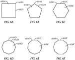
- FIGS. 6A-9E various examples of the non-circular shapes 600, 700, 800, 900 are shown.
- polygonal shapes 600A, 600B, 600C, 600D, 600E, 600F are shown in FIGS.
- each polygonal shape 600A, 600B, 600C, 600D, 600E, 600F including sides 602A, 602B, 602C, 602D, 602E, 602F meeting at corners 604A, 604B, 604C, 604D, 604E, 604F.
- FIGS. 6A-6F Although some polygonal shapes are shown in FIGS. 6A-6F , this is not intended to be all inclusive. As such, polygonal shapes in addition to those shown in FIGS. 6A-6F are contemplated herein.
- each of the polygonal shapes 600A, 600B, 600C, 600D, 600E, 600F shown include equilateral polygons, it is contemplated that the polygonal shapes include sides of different lengths to one another and corners having different angles to one another.
- FIGS. 7A-9E various examples of shapes 700, 800, 900 are shown with varying rounding of corners 704, 804, 904, 906 disposed between sides 702, 802, 902.
- a rectangle (specifically, a square) shape 700A, 700B, 700C, 700D is shown that is similar to the polygonal shape 600A of FIG. 6A .
- the square shape 700A, 700B, 700C, 700D includes increasing rounding of corners 704A, 704B, 704C, 704D between sides 702A, 702B, 702C, 702D, going from the lesser or no rounding of the corners 704A of FIG. 7A to the greater rounding of the corners 704D of FIG. 7D .
- a triangle shape 800A, 800B, 800C, 800D is shown.
- the triangle shape 800A, 800B, 800C, 800D includes increasing rounding of corners 804A, 804B, 804C, 804D between sides 802A, 802B, 802C, 802D, going from the lesser or no rounding of the corners 804A of FIG. 8A to the greater rounding of the corners 804D of FIG. 8D .
- the shape of the grip portion 320, 420 can include a star shape 900A, 900B, 900C, 900D, 900E.
- the star shape 900A, 900B, 900C, 900D, 900E includes increasing rounding of outer corners 904A, 904B, 904C, 904D, 904E and inner corners 906A, 906B, 906C, 906D, 906E between sides 902A, 902B, 902C, 902D, 902E, going from the lesser or no rounding of the corners 904A, 906A of FIG. 9A to the greater rounding of the corners 904E, 906E of FIG. 9E .
- FIGS. 7A-9E Although some shapes are shown in FIGS. 7A-9E , this is not intended to be all inclusive. As such, shapes in addition to those shown in FIGS. 7A-9E are contemplated herein. Additionally, although polygonal shapes are shown in FIGS. 7A-9E , it is contemplated that other shapes can be used for the grip portion 320, 420, such as, but not limited to elliptical, oval or egg-shaped, or the like. As such, in various examples, various shapes, as well as various amounts of rounding of corners of the shapes, of the grip portion 320, 420 are contemplated herein.
- At least the part of the grip portion 320, 420 of the core wire 310, 410 is twisted about the longitudinal axis 312, 412 of the core wire 310, 410 to rotate the non-circular shape 600, 700, 800, 900 along at least the part of the grip portion 320, 420.
- the various facets (such as the corners 604, 704, 804, 904, 906 and the sides 602, 702, 802, 902) of the shape 600, 700, 800, 900 of the grip portion 320, 420 are twisted about the longitudinal axis 312, 412 along at least a portion of the proximal portion 318, 418 of the core wire 310, 410 to create the grip pattern 321, 421 and, in turn, the tactile feel for the guidewire 300, 400.
- the shape 600, 700, 800, 900 of the grip portion 320, 420 is formed by drawing the core wire 310, 410 at least partially through a die with the desired shape.
- the shape 600, 700, 800, 900 of the grip portion 320, 420 can be formed by other mechanical methods such as, but not limited to, machining of the core wire 310, 410 to create the desired shape of the grip portion 320, 420.
- the shape 600, 700, 800, 900 is formed in the grip portion 320, 420 of the core wire 310, 410 by drawing at least a portion of the core wire 310, 410 through the die and twisting the at least the portion of the core wire 310, 410 while drawing to create an uneven surface of at least the portion of the core wire 310, 410, resulting in the tactile feel or grip on the core wire 310, 410.
- the core wire 310, 410 can still be processed as per a standard guidewire and/or ground or otherwise processed to create the distal portion 314, 414 or tip.
- the need for additional processing steps to create the tactile feel is reduced, if not eliminated.
- the twisted core wire 310, 410 can be coated (for instance, with PTFE) and maintain tactile feel.
- the tactile feel in some examples, can be adjusted by adjusting the pitch 321P, 421P of the grip pattern 321, 421 (for instance, increasing or decreasing the number of twists per unit length of the grip portion 320, 420) and/or changing the die shape or machining or otherwise forming the core wire 310, 410 differently to change the shape 600, 700, 800, 900 of the core wire 310, 410 at least at the grip portion 320, 420.
- the twist of the core wire 310, 410 can ensure that an outer diameter of the guidewire 300, 400 is in contact with the catheter or other interventional device, while, at the same time, a reduced contact area between the interventional device and the guidewire 300, 400 can allow for smoother catheter/device exchanges.
- the pitch 321P, 421P can be altered to reduce or increase the contact area. That is, the lower the pitch 321P, 421P, the less contact area and the lower the force needed to track the catheter or other interventional device over the guidewire 300, 400, and, in turn, the higher the pitch 321P, 421P, the more contact area and the higher the force needed to track the catheter or other interventional device over the guidewire 300, 400.
- the grip portion 520 includes a grip pattern 521 formed in the core wire 510.
- the grip pattern 521 includes at least one groove 522 cut or otherwise formed into the core wire 510.
- the groove 522 extends along at least part of the grip portion 520 of the core wire 510.
- the at least one groove 522 in some examples, is substantially helically or spirally extends along the core wire 510.
- the groove 522 substantially rotates around the longitudinal axis 512 of the core wire 510 as the groove 522 extends along at least a portion of the grip portion length 520L (as measured between a first end 521A of the grip pattern 521 and a second end 521B of the grip pattern 521) of the core wire 510.
- the core wire includes two or more grooves formed in the core wire depending upon the application for which the guidewire is to be used.
- a shape of the groove 522 and/or a path of the groove 522 along the core wire 510 can be varied depending upon the application for which the guidewire 500 is to be used and/or the desired tactile feel for the guidewire 500.
- the shape of the groove 522 (in cross section) can include a U-shape (with sharp corners, rounded corners, or a continuous curve), a V-shape, or other shapes.
- the groove 522 of the grip pattern 521 of the guidewire 500 includes a pitch 521P.
- pitch 521P is meant to mean rotations of the groove 500 around the core wire 510 per unit length of the guidewire 500.
- the example of the guidewire 500 shown in FIG. 5 includes the grip pattern 521 having a particular pitch 521P, this is but one example of many pitches that can be implemented on guidewires according to the present inventive subject matter. As such, in other examples, other pitches are contemplated herein, such that the pitch can be greater or less than the pitch 521P shown and described herein depending upon the application and/or desired tactile feel for the guidewire.
- the grip portion 520 of the guidewire 500 is shown extending the grip portion length 520L along substantially the entire proximal portion 518 of the core wire 510, in various other examples, it is contemplated that the grip portion can extend along the proximal portion of the core wire at various lengths other than substantially along the entire proximal portion of the core wire depending upon the application for the guidewire and the tactile feel desired for the guidewire.
- the groove 522 can be formed by various mechanical methods, such as, but not limited to, machining of the core wire 510 to create the desired groove 522 of the grip portion 520.
- the groove 522 522 can be formed by other mechanical methods, such as stamping.
- 522 can be formed by various non-mechanical methods, such as laser profiling, thermal processes, or energy processes.
- the core wire 510 after forming of the groove 522 of the grip portion 520 of the core wire 510, the core wire 510 can still be processed as per a standard guidewire and/or ground or otherwise processed to create the distal portion 514 or tip.
- the need for additional processing steps to create the tactile feel is reduced, if not eliminated.
- the core wire 510 can be coated (for instance, with PTFE) and maintain tactile feel.
- the tactile feel in some examples, can be adjusted by adjusting the pitch 521P of the groove 522 of the grip pattern 521 (for instance, increasing or decreasing the number of rotations of the groove 522 per unit length of the grip portion 520).
- the groove 522 of the core wire 510 can ensure that an outer diameter of the guidewire 500 is in contact with the catheter or other interventional device, while, at the same time, a reduced contact area between the interventional device and the guidewire 500 can allow for smoother catheter/device exchanges.
- the pitch 521P can be altered to reduce or increase the contact area. That is, the lower the pitch 521P, the less contact area and the lower the force needed to track the catheter or other interventional device over the guidewire 500, and, in turn, the higher the pitch 521P, the more contact area and the higher the force needed to track the catheter or other interventional device over the guidewire 500.
- the core wire 110, 210 is provided 1002, the core wire 110, 210 including a substantially round cross-sectional shape.
- the core wire 110, 210 can be coated 1004 (with PTFE or another coating, for instance) and/or ground down 1006 (for instance to form the distal portion 114, 214; the transition portion 116, 216; and/or the proximal portion 118, 218).
- the core wire 110, 210 can be coated 1004 before and/or after being ground down 1006.
- the elongate core wire 110, 210 is formed, with the core wire 110, 210 including the distal end 110A, 210A; the proximal end 110B, 210B; and the longitudinal axis 112, 212 extending along the length 110L, 210L of the core wire 110, 210 from the distal end 110A, 210A to the proximal end 110B, 210B.
- the grip portion 120, 220 is then formed on the core wire 110, 210, the grip portion 120, 220 being configured to provide tactile feel to the user of the guidewire 100, 200.
- the grip portion 120, 220 is formed on the core wire 110, 210 proximate the proximal end 118, 218 of the core wire 110, 210.
- Forming the grip portion 120, 220 includes cutting 1008 the polymer tube 122, 222 with the desired cut pattern 121, 221. This includes cutting the at least one cutout 124, 224 through the sidewall 123, 223 of the polymer tube 122, 222. In some examples, the at least one cutout 124, 224 is cut completely through a thickness of the sidewall 123, 223 of the polymer tube 122, 222. In other examples, the at least one cutout 124, 224 is cut partially through the thickness of the sidewall 123, 223 of the polymer tube 122, 222.
- the polymer tube 122, 222 includes the sidewall 123, 223 extending between the first end 122A, 222A and the second end 122B, 222B of the polymer tube 122, 222.
- the at least one cutout 124, 224 forms the cut pattern 121, 221 of the grip portion 120, 220.
- a plurality of cutouts 124, 224 disposed within the sidewall 123, 223 of the polymer tube 122, 222 forms the cut pattern 121, 221 of the grip portion 120, 220.
- the one or more cutouts 124, 224 of the cut pattern 121, 221 are laser cut in the polymer tube 122, 222.
- the one or more cutouts 124, 224 of the cut pattern 121, 221 are otherwise formed into the polymer tube 122, 222, including, but not limited to, being mechanically cut or machined into the polymer tube 122, 222, being formed into the polymer tube 122, 222 by rolling a hot roller over the polymer tube 122, 222, or the like.
- the polymer tube 122, 222 is be attached to the core wire 110, 210.
- the polymer tube 122, 222 is attached by heat shrinking 1010 the polymer tube 122, 222 to the core wire 110, 210.
- the cut pattern 121, 221 is formed into the polymer tube 122, 222 prior to attachment of the polymer tube 122, 222 to the core wire 110, 210.
- the cut pattern 121, 221 is formed into the polymer tube 122, 222 after attachment of the polymer tube 122, 222 to the core wire 110, 210.
- final guidewire assembly 1012 occurs during which various aspects of the guidewire 100, 200 are finalized.
- Such aspects include, but are not limited to, one or more coatings being applied to the guidewire 100, 200; the coil 130, 230 being attached to the distal portion 114, 214 of the core wire 110, 210; jacketing the core wire 110, 210; and/or the like.
- the core wire 310, 410 is shaped and twisted 1102.
- the core wire 310, 410 includes at least a portion that includes the grip pattern 321, 421.
- the grip pattern 321, 421 includes a substantially non-circular cross-sectional shape 600, 700, 800, 900 twisted at the desired pitch 321P, 421P to form the grip portion 320, 420.
- the non-circular shape 600, 700, 800, 900 is formed by drawing at least a portion of the core wire 310, 410 through a complementarily-shaped die.
- the non-circular shape 600, 700, 800, 900 can be formed by mechanical methods, such as machining, for instance.
- at least the part of the grip portion 320, 420 of the core wire 310, 410 is twisted about the longitudinal axis 312, 412 of the core wire 310, 410 to rotate the non-circular shape 600, 700, 800, 900 along at least the part of the grip portion 320, 420.
- the core wire 310, 410 can be coated 1104 (with PTFE or another coating, for instance) and/or ground down 1106 (for instance to form the distal portion 314, 414; the transition portion 316, 416; and/or the proximal portion 318, 418). In some examples, the core wire 310, 410 can be coated 1104 before and/or after being ground down 1106.
- the elongate core wire 310, 410 is formed, with the core wire 310, 410 including the distal end 310A, 410A; the proximal end 310B, 410B; and the longitudinal axis 312, 412 extending along the length 310L, 410L of the core wire 310, 410 from the distal end 310A, 410A to the proximal end 310B, 410B.
- the grip portion 320, 420 formed on the core wire 310, 410 is configured to provide tactile feel to the user of the guidewire 300, 400.
- the grip portion 320, 420 is formed on the core wire 310, 410 proximate the proximal end 318, 418 of the core wire 310, 410.
- final guidewire assembly 1108 occurs during which various aspects of the guidewire 300, 400 are finalized.
- Such aspects include, but are not limited to, one or more coatings being applied to the guidewire 300, 400; the coil 330, 430 being attached to the distal portion 314, 414 of the core wire 310, 410; jacketing the core wire 310, 410; and/or the like.
- the core wire 510 is provided 1202, the core wire 510 including a substantially round cross-sectional shape.
- the grip portion 520 is then formed 1204 on the core wire 510, the grip portion 520 being configured to provide tactile feel to the user of the guidewire 500.
- the grip portion 520 is formed on the core wire 510 proximate the proximal end 518 of the core wire 510.
- the core wire 510 includes at least a portion that includes the grip pattern 521.
- the grip pattern 521 is formed in the core wire 510 by cutting the at least one groove 522 into the core wire 510, the groove 522 extending along at least part of the grip portion 520 of the core wire 510.
- the at least one groove 522 is helically or spirally cut into the core wire 510 so that the at least one groove 522 helically or spirally extends along the core wire 510.
- the core wire 510 can be coated 1206 (with PTFE or another coating, for instance) and/or ground down 1208 (for instance to form the distal portion 514; the transition portion 516; and/or the proximal portion 518). In some examples, the core wire 510 can be coated 1206 before and/or after being ground down 1208. In this way, in some examples, the elongate core wire 510 is formed, with the core wire 510 including the distal end 510A; the proximal end 510B; and the longitudinal axis 512 extending along the length 510L of the core wire 510 from the distal end 510A to the proximal end 510B.
- final guidewire assembly 1210 occurs during which various aspects of the guidewire 500 are finalized.
- aspects include, but are not limited to, one or more coatings being applied to the guidewire 500; the coil 530 being attached to the distal portion 514 of the core wire 510; jacketing the core wire 510; and/or the like.
- the present inventors have recognized various advantages of the subject matter described herein.
- the present inventors have recognized, among other things, that the present subject matter can be used to provide a guidewire with tactile feel to satisfy design requirements required by physicians by incorporating the tactile feel into the guidewire.
- the present subject matter is advantageous in that it provides for a guidewire that includes a grip portion to enhance tactile feel, handling, control, and advancement recognition for the physician or other user of the guidewire.
- the present invention facilitates tracking of a catheter or other indicated interventional device over the guidewire by reducing a force needed to do so. While various advantages of the example systems are listed herein, this list is not considered to be complete, as further advantages may become apparent from the description and figures presented herein.
- the terms “a” or “an” are used to include one or more than one, independent of any other instances or usages of “at least one” or “one or more.”
- the term “or” is used to refer to a nonexclusive or, such that “A or B” includes “A but not B,” “B but not A,” and “A and B,” unless otherwise indicated.
- the terms “about” and “approximately” or similar are used to refer to an amount that is nearly, almost, or in the vicinity of being equal to a stated amount.
Landscapes
- Health & Medical Sciences (AREA)
- Life Sciences & Earth Sciences (AREA)
- Biophysics (AREA)
- Pulmonology (AREA)
- Engineering & Computer Science (AREA)
- Anesthesiology (AREA)
- Biomedical Technology (AREA)
- Heart & Thoracic Surgery (AREA)
- Hematology (AREA)
- Animal Behavior & Ethology (AREA)
- General Health & Medical Sciences (AREA)
- Public Health (AREA)
- Veterinary Medicine (AREA)
- Media Introduction/Drainage Providing Device (AREA)
Claims (15)
- Führungsdraht (100), der Folgendes umfasst:einen länglichen Kerndraht (110) mit einem distalen Ende (110A), einem proximalen Ende (110B) und einer Längsachse (112), die sich entlang einer Länge (110L) des Kerndrahts von dem distalen Ende zu dem proximalen Ende erstreckt; undeinen Griffabschnitt (120), der an dem Kerndraht angeordnet ist, wobei der Griffabschnitt dafür konfiguriert ist, einem Benutzer des Führungsdrahts ein taktiles Gefühl zu vermitteln;dadurch gekennzeichnet, dass der Griffabschnitt einen Polymerschlauch (122) umfasst, der auf den Kerndraht aufgebracht ist, wobei der Polymerschlauch (122) eine Seitenwand (123), die sich zwischen einem ersten (122A) und einem zweiten (122B) Ende des Polymerschlauches erstreckt, und mindestens einen Ausschnitt (124) durch die Seitenwand des Polymerschlauches umfasst.
- Führungsdraht nach Anspruch 1, wobei der Kerndraht (110) einen distalen Abschnitt (114), der sich proximal von dem distalen Ende erstreckt, und einen proximalen Abschnitt (118), der sich distal von dem proximalen Ende erstreckt, umfasst, wobei der distale Abschnitt ein distales Profil (115) umfasst und der proximale Abschnitt ein proximales Profil (119) umfasst, wobei das distale Profil kleiner ist als das proximale Profil.
- Führungsdraht nach Anspruch 2, wobei sich der Griffabschnitt (120) mindestens teilweise entlang des proximalen Abschnitts des Kerndrahts erstreckt.
- Führungsdraht nach einem der vorhergehenden Ansprüche, wobei die mindestens eine Aussparung (124) eine Vielzahl von Aussparungen umfasst, die innerhalb der Seitenwand des Polymerrohrs angeordnet sind, um ein Schnittmuster des Griffabschnitts zu formen.
- Führungsdraht nach einem der vorhergehenden Ansprüche, wobei der mindestens eine Ausschnitt (124) mindestens einen Laserausschnitt durch die Seitenwand des Polymerrohrs aufweist.
- Führungsdraht nach einem der vorhergehenden Ansprüche, wobei der Polymerschlauch (122) einen wärmeschrumpfenden Polymerschlauch umfasst.
- Führungsdraht nach einem der vorhergehenden Ansprüche, wobei der Griffabschnitt (120) ein im Kerndraht geformtes Griffmuster (321) umfasst.
- Führungsdraht nach Anspruch 7, wobei das Griffmuster (321) mindestens eine in den Kerndraht geschnittene Rille umfasst, wobei sich die Rille mindestens entlang eines Teils des Griffbereichs des Kerndrahts erstreckt.
- Führungsdraht nach Anspruch 8, wobei sich die mindestens eine Rille (522) spiralförmig entlang des Kerndrahts erstreckt.
- Führungsdraht nach Anspruch 7 oder Anspruch 8, wobei das Griffmuster mindestens einen Teil des Griffabschnitts des Kerndrahts umfasst, der eine nicht kreisförmige Form umfasst, wobei mindestens der Teil des Griffabschnitts des Kerndrahts um die Längsachse des Kerndrahts verdreht ist, um die nicht kreisförmige Form entlang mindestens des Teils des Griffabschnitts zu drehen.
- Verfahren zur Herstellung eines Führungsdrahts mit taktilem Gefühl, wobei das Verfahren Folgendes umfasst:Formen eines länglichen Kerndrahts (110), wobei der Kerndraht ein distales Ende, ein proximales Ende und eine Längsachse umfasst, die sich entlang der Länge des Kerndrahts von dem distalen Ende zu dem proximalen Ende erstreckt; undFormen eines Griffabschnitts (120) an dem Kerndraht, wobei der Griffabschnitt dafür konfiguriert ist, einem Benutzer des Führungsdrahts ein taktiles Gefühl zu vermitteln;wobei das Formen des Griffabschnitts Folgendes umfasst:Schneiden mindestens eines Ausschnitts (124) durch eine Seitenwand eines Polymerschlauchs (122), wobei der Polymerschlauch die Seitenwand umfasst, die sich zwischen einem ersten und einem zweiten Ende des Polymerschlauchs erstreckt; undAnbringen des Polymerrohrs an den Kerndraht, wobei der mindestens eine Ausschnitt ein Schnittmuster des Griffabschnitts formt.
- Verfahren nach Anspruch 11, wobei das Aufbringen des Polymerschlauches das Wärmeschrumpfen des Polymerschlauches auf den Kerndraht umfasst.
- Verfahren nach Anspruch 11 oder Anspruch 12, wobei das Formen des Griffabschnitts das Formen eines Griffmusters in dem Kerndraht umfasst, einschließlich des Einschneidens mindestens einer Rille in den Kerndraht, wobei sich die Rille entlang mindestens eines Teils des Griffabschnitts des Kerndrahts erstreckt.
- Verfahren nach Anspruch 13, wobei das Schneiden der mindestens einen Rille in den Kerndraht das spiralförmige Schneiden der mindestens einen Rille in den Kerndraht umfasst, so dass sich die mindestens eine Rille spiralförmig entlang des Kerndrahts erstreckt.
- Verfahren nach einem der Ansprüche 11 bis 14, wobei das Formen des Griffabschnitts das Formen eines Griffmusters in dem Kerndraht umfasst, das Folgendes umfasst:Formen mindestens eines Teils des Griffabschnitts des Kerndrahts in eine nicht kreisförmige Form; undVerdrehen mindestens des Teils des Griffabschnitts des Kerndrahts um die Längsachse des Kerndrahts, um die nicht kreisförmige Form entlang mindestens des Teils des Griffabschnitts zu drehen.
Applications Claiming Priority (2)
| Application Number | Priority Date | Filing Date | Title |
|---|---|---|---|
| US201962838355P | 2019-04-25 | 2019-04-25 | |
| US201962838357P | 2019-04-25 | 2019-04-25 |
Publications (2)
| Publication Number | Publication Date |
|---|---|
| EP3730179A1 EP3730179A1 (de) | 2020-10-28 |
| EP3730179B1 true EP3730179B1 (de) | 2022-10-12 |
Family
ID=70464888
Family Applications (1)
| Application Number | Title | Priority Date | Filing Date |
|---|---|---|---|
| EP20171358.3A Active EP3730179B1 (de) | 2019-04-25 | 2020-04-24 | Führungsdraht mit taktiler haptik |
Country Status (2)
| Country | Link |
|---|---|
| US (2) | US20200338318A1 (de) |
| EP (1) | EP3730179B1 (de) |
Families Citing this family (3)
| Publication number | Priority date | Publication date | Assignee | Title |
|---|---|---|---|---|
| US20200338318A1 (en) * | 2019-04-25 | 2020-10-29 | Lake Region Medical, Inc. | Guidewire with tactile feel |
| CN115605253B (zh) * | 2020-06-10 | 2026-03-24 | 巴德股份有限公司 | 具有增强的可推动性和可操纵性的刻划球囊导管 |
| US20260115429A1 (en) * | 2024-10-31 | 2026-04-30 | Bard Access Systems, Inc. | Tactile-Feedback System and Method for Guidewire-Containing Medical Devices |
Family Cites Families (18)
| Publication number | Priority date | Publication date | Assignee | Title |
|---|---|---|---|---|
| US5095915A (en) * | 1990-03-19 | 1992-03-17 | Target Therapeutics | Guidewire with flexible distal tip |
| US5358493A (en) * | 1993-02-18 | 1994-10-25 | Scimed Life Systems, Inc. | Vascular access catheter and methods for manufacture thereof |
| US5666969A (en) * | 1994-05-18 | 1997-09-16 | Scimed Life Systems, Inc. | Guidewire having multiple radioscopic coils |
| US7455646B2 (en) * | 1997-06-04 | 2008-11-25 | Advanced Cardiovascular Systems, Inc. | Polymer coated guide wire |
| US20040167439A1 (en) * | 2003-02-26 | 2004-08-26 | Sharrow James S. | Guidewire having textured proximal portion |
| US8613712B1 (en) * | 2003-09-16 | 2013-12-24 | Abbott Cardiovascular Systems Inc. | Textured polymer coated guide wire and method of manufacture |
| EP2103323B1 (de) * | 2007-03-14 | 2012-04-25 | Terumo Kabushiki Kaisha | Führungsdraht |
| US9387308B2 (en) * | 2007-04-23 | 2016-07-12 | Cardioguidance Biomedical, Llc | Guidewire with adjustable stiffness |
| JP5147569B2 (ja) * | 2008-06-30 | 2013-02-20 | テルモ株式会社 | ガイドワイヤ |
| EP2552530A1 (de) * | 2010-03-31 | 2013-02-06 | Boston Scientific Scimed, Inc. | Führungsdraht mit einem biegefestigkeitsprofil |
| US11373780B2 (en) * | 2011-10-06 | 2022-06-28 | 3Dt Holdings, Llc | Methods to generate elongated wires having a metallic substrate thereon and devices comprising the same |
| US9734938B2 (en) * | 2011-10-06 | 2017-08-15 | 3Dt Holdings, Llc | Devices and systems for obtaining conductance data and methods of manufacturing and using the same |
| US10499820B2 (en) * | 2013-05-22 | 2019-12-10 | Boston Scientific Scimed, Inc. | Pressure sensing guidewire systems including an optical connector cable |
| WO2015187385A1 (en) * | 2014-06-04 | 2015-12-10 | Boston Scientific Scimed, Inc. | Pressure sensing guidewire systems with reduced pressure offsets |
| WO2016019207A1 (en) * | 2014-08-01 | 2016-02-04 | Boston Scientific Scimed, Inc. | Pressure sensing guidewires |
| EP3226748B1 (de) * | 2014-12-05 | 2020-11-04 | Boston Scientific Scimed, Inc. | Druckmessungsführungsdrähte |
| US10953204B2 (en) * | 2017-01-09 | 2021-03-23 | Boston Scientific Scimed, Inc. | Guidewire with tactile feel |
| US20200338318A1 (en) * | 2019-04-25 | 2020-10-29 | Lake Region Medical, Inc. | Guidewire with tactile feel |
-
2020
- 2020-04-24 US US16/857,313 patent/US20200338318A1/en not_active Abandoned
- 2020-04-24 EP EP20171358.3A patent/EP3730179B1/de active Active
-
2022
- 2022-07-13 US US17/863,612 patent/US20220347439A1/en active Pending
Also Published As
| Publication number | Publication date |
|---|---|
| US20220347439A1 (en) | 2022-11-03 |
| US20200338318A1 (en) | 2020-10-29 |
| EP3730179A1 (de) | 2020-10-28 |
Similar Documents
| Publication | Publication Date | Title |
|---|---|---|
| US20220347439A1 (en) | Guidewire with tactile feel | |
| US8551073B2 (en) | Catheter device | |
| DE69636213T2 (de) | Hohlgewickelter Führungsdraht für einen Katheter | |
| EP2788067B1 (de) | Verstärkte längliche medizinische vorrichtung und herstellungsverfahren | |
| US20080255654A1 (en) | System for delivering a stent | |
| US20020151823A1 (en) | Wire-stranded hollow tube, a medical tube body and a medical guide wire | |
| KR102125315B1 (ko) | 개선된 강성을 가진 뒤틀림-저항성 가이드와이어 | |
| US20100036364A1 (en) | Catheter Introducer | |
| US20040167439A1 (en) | Guidewire having textured proximal portion | |
| JP2002325629A (ja) | ケラチン質繊維に物質を付けるブラシ | |
| WO2016047499A1 (ja) | ガイドワイヤ | |
| JP5619426B2 (ja) | 医療用長尺体、その製造方法およびその製造装置 | |
| JP2011212493A (ja) | バルーンカテーテル | |
| CN114887199B (zh) | 导丝 | |
| WO1985001444A1 (fr) | Mandrin de guidage pour catheter et instruments similaires et son procede de fabrication | |
| CN113597323A (zh) | 导丝 | |
| US20200306509A1 (en) | Guidewire and method therefor | |
| US20240173523A1 (en) | Guidewire and method therefor | |
| CA2346822A1 (en) | Improved guidewire | |
| JP7529799B2 (ja) | ガイドワイヤ | |
| HK1068823B (en) | Catheter and hollow tube being incorporated therein |
Legal Events
| Date | Code | Title | Description |
|---|---|---|---|
| PUAI | Public reference made under article 153(3) epc to a published international application that has entered the european phase |
Free format text: ORIGINAL CODE: 0009012 |
|
| STAA | Information on the status of an ep patent application or granted ep patent |
Free format text: STATUS: THE APPLICATION HAS BEEN PUBLISHED |
|
| AK | Designated contracting states |
Kind code of ref document: A1 Designated state(s): AL AT BE BG CH CY CZ DE DK EE ES FI FR GB GR HR HU IE IS IT LI LT LU LV MC MK MT NL NO PL PT RO RS SE SI SK SM TR |
|
| AX | Request for extension of the european patent |
Extension state: BA ME |
|
| STAA | Information on the status of an ep patent application or granted ep patent |
Free format text: STATUS: REQUEST FOR EXAMINATION WAS MADE |
|
| 17P | Request for examination filed |
Effective date: 20201218 |
|
| RBV | Designated contracting states (corrected) |
Designated state(s): AL AT BE BG CH CY CZ DE DK EE ES FI FR GB GR HR HU IE IS IT LI LT LU LV MC MK MT NL NO PL PT RO RS SE SI SK SM TR |
|
| RIN1 | Information on inventor provided before grant (corrected) |
Inventor name: BROGAN, JAMES Inventor name: MC ALLISTER, GORDON Inventor name: KEARY, DAVID Inventor name: FREELEY, JOE Inventor name: HUNT, RHONA |
|
| RIC1 | Information provided on ipc code assigned before grant |
Ipc: A61M 25/09 20060101AFI20220607BHEP |
|
| GRAP | Despatch of communication of intention to grant a patent |
Free format text: ORIGINAL CODE: EPIDOSNIGR1 |
|
| STAA | Information on the status of an ep patent application or granted ep patent |
Free format text: STATUS: GRANT OF PATENT IS INTENDED |
|
| INTG | Intention to grant announced |
Effective date: 20220719 |
|
| RIN1 | Information on inventor provided before grant (corrected) |
Inventor name: FREELEY, JOE Inventor name: BROGAN, JAMES Inventor name: HUNT, RHONA Inventor name: MC ALLISTER, GORDON Inventor name: KEARY, DAVID |
|
| GRAS | Grant fee paid |
Free format text: ORIGINAL CODE: EPIDOSNIGR3 |
|
| GRAA | (expected) grant |
Free format text: ORIGINAL CODE: 0009210 |
|
| STAA | Information on the status of an ep patent application or granted ep patent |
Free format text: STATUS: THE PATENT HAS BEEN GRANTED |
|
| RIN1 | Information on inventor provided before grant (corrected) |
Inventor name: FREELEY, JOE Inventor name: BROGAN, JAMES Inventor name: HUNT, RHONA Inventor name: MC ALLISTER, GORDON Inventor name: KEARY, DAVID |
|
| AK | Designated contracting states |
Kind code of ref document: B1 Designated state(s): AL AT BE BG CH CY CZ DE DK EE ES FI FR GB GR HR HU IE IS IT LI LT LU LV MC MK MT NL NO PL PT RO RS SE SI SK SM TR |
|
| REG | Reference to a national code |
Ref country code: GB Ref legal event code: FG4D |
|
| REG | Reference to a national code |
Ref country code: CH Ref legal event code: EP |
|
| REG | Reference to a national code |
Ref country code: DE Ref legal event code: R096 Ref document number: 602020005553 Country of ref document: DE |
|
| REG | Reference to a national code |
Ref country code: IE Ref legal event code: FG4D |
|
| REG | Reference to a national code |
Ref country code: AT Ref legal event code: REF Ref document number: 1523786 Country of ref document: AT Kind code of ref document: T Effective date: 20221115 |
|
| REG | Reference to a national code |
Ref country code: LT Ref legal event code: MG9D |
|
| REG | Reference to a national code |
Ref country code: NL Ref legal event code: MP Effective date: 20221012 |
|
| REG | Reference to a national code |
Ref country code: AT Ref legal event code: MK05 Ref document number: 1523786 Country of ref document: AT Kind code of ref document: T Effective date: 20221012 |
|
| PG25 | Lapsed in a contracting state [announced via postgrant information from national office to epo] |
Ref country code: NL Free format text: LAPSE BECAUSE OF FAILURE TO SUBMIT A TRANSLATION OF THE DESCRIPTION OR TO PAY THE FEE WITHIN THE PRESCRIBED TIME-LIMIT Effective date: 20221012 |
|
| PG25 | Lapsed in a contracting state [announced via postgrant information from national office to epo] |
Ref country code: SE Free format text: LAPSE BECAUSE OF FAILURE TO SUBMIT A TRANSLATION OF THE DESCRIPTION OR TO PAY THE FEE WITHIN THE PRESCRIBED TIME-LIMIT Effective date: 20221012 Ref country code: PT Free format text: LAPSE BECAUSE OF FAILURE TO SUBMIT A TRANSLATION OF THE DESCRIPTION OR TO PAY THE FEE WITHIN THE PRESCRIBED TIME-LIMIT Effective date: 20230213 Ref country code: NO Free format text: LAPSE BECAUSE OF FAILURE TO SUBMIT A TRANSLATION OF THE DESCRIPTION OR TO PAY THE FEE WITHIN THE PRESCRIBED TIME-LIMIT Effective date: 20230112 Ref country code: LT Free format text: LAPSE BECAUSE OF FAILURE TO SUBMIT A TRANSLATION OF THE DESCRIPTION OR TO PAY THE FEE WITHIN THE PRESCRIBED TIME-LIMIT Effective date: 20221012 Ref country code: FI Free format text: LAPSE BECAUSE OF FAILURE TO SUBMIT A TRANSLATION OF THE DESCRIPTION OR TO PAY THE FEE WITHIN THE PRESCRIBED TIME-LIMIT Effective date: 20221012 Ref country code: ES Free format text: LAPSE BECAUSE OF FAILURE TO SUBMIT A TRANSLATION OF THE DESCRIPTION OR TO PAY THE FEE WITHIN THE PRESCRIBED TIME-LIMIT Effective date: 20221012 Ref country code: AT Free format text: LAPSE BECAUSE OF FAILURE TO SUBMIT A TRANSLATION OF THE DESCRIPTION OR TO PAY THE FEE WITHIN THE PRESCRIBED TIME-LIMIT Effective date: 20221012 |
|
| PG25 | Lapsed in a contracting state [announced via postgrant information from national office to epo] |
Ref country code: RS Free format text: LAPSE BECAUSE OF FAILURE TO SUBMIT A TRANSLATION OF THE DESCRIPTION OR TO PAY THE FEE WITHIN THE PRESCRIBED TIME-LIMIT Effective date: 20221012 Ref country code: PL Free format text: LAPSE BECAUSE OF FAILURE TO SUBMIT A TRANSLATION OF THE DESCRIPTION OR TO PAY THE FEE WITHIN THE PRESCRIBED TIME-LIMIT Effective date: 20221012 Ref country code: LV Free format text: LAPSE BECAUSE OF FAILURE TO SUBMIT A TRANSLATION OF THE DESCRIPTION OR TO PAY THE FEE WITHIN THE PRESCRIBED TIME-LIMIT Effective date: 20221012 Ref country code: IS Free format text: LAPSE BECAUSE OF FAILURE TO SUBMIT A TRANSLATION OF THE DESCRIPTION OR TO PAY THE FEE WITHIN THE PRESCRIBED TIME-LIMIT Effective date: 20230212 Ref country code: HR Free format text: LAPSE BECAUSE OF FAILURE TO SUBMIT A TRANSLATION OF THE DESCRIPTION OR TO PAY THE FEE WITHIN THE PRESCRIBED TIME-LIMIT Effective date: 20221012 Ref country code: GR Free format text: LAPSE BECAUSE OF FAILURE TO SUBMIT A TRANSLATION OF THE DESCRIPTION OR TO PAY THE FEE WITHIN THE PRESCRIBED TIME-LIMIT Effective date: 20230113 |
|
| REG | Reference to a national code |
Ref country code: DE Ref legal event code: R097 Ref document number: 602020005553 Country of ref document: DE |
|
| PG25 | Lapsed in a contracting state [announced via postgrant information from national office to epo] |
Ref country code: SM Free format text: LAPSE BECAUSE OF FAILURE TO SUBMIT A TRANSLATION OF THE DESCRIPTION OR TO PAY THE FEE WITHIN THE PRESCRIBED TIME-LIMIT Effective date: 20221012 Ref country code: RO Free format text: LAPSE BECAUSE OF FAILURE TO SUBMIT A TRANSLATION OF THE DESCRIPTION OR TO PAY THE FEE WITHIN THE PRESCRIBED TIME-LIMIT Effective date: 20221012 Ref country code: EE Free format text: LAPSE BECAUSE OF FAILURE TO SUBMIT A TRANSLATION OF THE DESCRIPTION OR TO PAY THE FEE WITHIN THE PRESCRIBED TIME-LIMIT Effective date: 20221012 Ref country code: DK Free format text: LAPSE BECAUSE OF FAILURE TO SUBMIT A TRANSLATION OF THE DESCRIPTION OR TO PAY THE FEE WITHIN THE PRESCRIBED TIME-LIMIT Effective date: 20221012 Ref country code: CZ Free format text: LAPSE BECAUSE OF FAILURE TO SUBMIT A TRANSLATION OF THE DESCRIPTION OR TO PAY THE FEE WITHIN THE PRESCRIBED TIME-LIMIT Effective date: 20221012 |
|
| PLBE | No opposition filed within time limit |
Free format text: ORIGINAL CODE: 0009261 |
|
| STAA | Information on the status of an ep patent application or granted ep patent |
Free format text: STATUS: NO OPPOSITION FILED WITHIN TIME LIMIT |
|
| PG25 | Lapsed in a contracting state [announced via postgrant information from national office to epo] |
Ref country code: SK Free format text: LAPSE BECAUSE OF FAILURE TO SUBMIT A TRANSLATION OF THE DESCRIPTION OR TO PAY THE FEE WITHIN THE PRESCRIBED TIME-LIMIT Effective date: 20221012 Ref country code: AL Free format text: LAPSE BECAUSE OF FAILURE TO SUBMIT A TRANSLATION OF THE DESCRIPTION OR TO PAY THE FEE WITHIN THE PRESCRIBED TIME-LIMIT Effective date: 20221012 |
|
| 26N | No opposition filed |
Effective date: 20230713 |
|
| PG25 | Lapsed in a contracting state [announced via postgrant information from national office to epo] |
Ref country code: SI Free format text: LAPSE BECAUSE OF FAILURE TO SUBMIT A TRANSLATION OF THE DESCRIPTION OR TO PAY THE FEE WITHIN THE PRESCRIBED TIME-LIMIT Effective date: 20221012 |
|
| REG | Reference to a national code |
Ref country code: CH Ref legal event code: PL |
|
| PG25 | Lapsed in a contracting state [announced via postgrant information from national office to epo] |
Ref country code: LU Free format text: LAPSE BECAUSE OF NON-PAYMENT OF DUE FEES Effective date: 20230424 |
|
| REG | Reference to a national code |
Ref country code: BE Ref legal event code: MM Effective date: 20230430 |
|
| PG25 | Lapsed in a contracting state [announced via postgrant information from national office to epo] |
Ref country code: MC Free format text: LAPSE BECAUSE OF FAILURE TO SUBMIT A TRANSLATION OF THE DESCRIPTION OR TO PAY THE FEE WITHIN THE PRESCRIBED TIME-LIMIT Effective date: 20221012 |
|
| PG25 | Lapsed in a contracting state [announced via postgrant information from national office to epo] |
Ref country code: MC Free format text: LAPSE BECAUSE OF FAILURE TO SUBMIT A TRANSLATION OF THE DESCRIPTION OR TO PAY THE FEE WITHIN THE PRESCRIBED TIME-LIMIT Effective date: 20221012 Ref country code: LI Free format text: LAPSE BECAUSE OF NON-PAYMENT OF DUE FEES Effective date: 20230430 Ref country code: CH Free format text: LAPSE BECAUSE OF NON-PAYMENT OF DUE FEES Effective date: 20230430 |
|
| REG | Reference to a national code |
Ref country code: IE Ref legal event code: MM4A |
|
| PG25 | Lapsed in a contracting state [announced via postgrant information from national office to epo] |
Ref country code: BE Free format text: LAPSE BECAUSE OF NON-PAYMENT OF DUE FEES Effective date: 20230430 |
|
| PG25 | Lapsed in a contracting state [announced via postgrant information from national office to epo] |
Ref country code: IE Free format text: LAPSE BECAUSE OF NON-PAYMENT OF DUE FEES Effective date: 20230424 |
|
| PG25 | Lapsed in a contracting state [announced via postgrant information from national office to epo] |
Ref country code: IE Free format text: LAPSE BECAUSE OF NON-PAYMENT OF DUE FEES Effective date: 20230424 |
|
| PG25 | Lapsed in a contracting state [announced via postgrant information from national office to epo] |
Ref country code: IT Free format text: LAPSE BECAUSE OF FAILURE TO SUBMIT A TRANSLATION OF THE DESCRIPTION OR TO PAY THE FEE WITHIN THE PRESCRIBED TIME-LIMIT Effective date: 20221012 |
|
| PG25 | Lapsed in a contracting state [announced via postgrant information from national office to epo] |
Ref country code: BG Free format text: LAPSE BECAUSE OF FAILURE TO SUBMIT A TRANSLATION OF THE DESCRIPTION OR TO PAY THE FEE WITHIN THE PRESCRIBED TIME-LIMIT Effective date: 20221012 |
|
| PG25 | Lapsed in a contracting state [announced via postgrant information from national office to epo] |
Ref country code: BG Free format text: LAPSE BECAUSE OF FAILURE TO SUBMIT A TRANSLATION OF THE DESCRIPTION OR TO PAY THE FEE WITHIN THE PRESCRIBED TIME-LIMIT Effective date: 20221012 |
|
| GBPC | Gb: european patent ceased through non-payment of renewal fee |
Effective date: 20240424 |
|
| PG25 | Lapsed in a contracting state [announced via postgrant information from national office to epo] |
Ref country code: GB Free format text: LAPSE BECAUSE OF NON-PAYMENT OF DUE FEES Effective date: 20240424 |
|
| PG25 | Lapsed in a contracting state [announced via postgrant information from national office to epo] |
Ref country code: GB Free format text: LAPSE BECAUSE OF NON-PAYMENT OF DUE FEES Effective date: 20240424 |
|
| PGFP | Annual fee paid to national office [announced via postgrant information from national office to epo] |
Ref country code: FR Payment date: 20250310 Year of fee payment: 6 |
|
| PGFP | Annual fee paid to national office [announced via postgrant information from national office to epo] |
Ref country code: DE Payment date: 20250305 Year of fee payment: 6 |
|
| PG25 | Lapsed in a contracting state [announced via postgrant information from national office to epo] |
Ref country code: CY Free format text: LAPSE BECAUSE OF FAILURE TO SUBMIT A TRANSLATION OF THE DESCRIPTION OR TO PAY THE FEE WITHIN THE PRESCRIBED TIME-LIMIT; INVALID AB INITIO Effective date: 20200424 |
|
| PG25 | Lapsed in a contracting state [announced via postgrant information from national office to epo] |
Ref country code: HU Free format text: LAPSE BECAUSE OF FAILURE TO SUBMIT A TRANSLATION OF THE DESCRIPTION OR TO PAY THE FEE WITHIN THE PRESCRIBED TIME-LIMIT; INVALID AB INITIO Effective date: 20200424 |
|
| PG25 | Lapsed in a contracting state [announced via postgrant information from national office to epo] |
Ref country code: TR Free format text: LAPSE BECAUSE OF FAILURE TO SUBMIT A TRANSLATION OF THE DESCRIPTION OR TO PAY THE FEE WITHIN THE PRESCRIBED TIME-LIMIT Effective date: 20221012 |