EP3730057A1 - Method and apparatus for generating a panoramic layer image - Google Patents
Method and apparatus for generating a panoramic layer image Download PDFInfo
- Publication number
- EP3730057A1 EP3730057A1 EP19171428.6A EP19171428A EP3730057A1 EP 3730057 A1 EP3730057 A1 EP 3730057A1 EP 19171428 A EP19171428 A EP 19171428A EP 3730057 A1 EP3730057 A1 EP 3730057A1
- Authority
- EP
- European Patent Office
- Prior art keywords
- ray
- layer image
- image
- panoramic
- ray projection
- Prior art date
- Legal status (The legal status is an assumption and is not a legal conclusion. Google has not performed a legal analysis and makes no representation as to the accuracy of the status listed.)
- Granted
Links
Images


Classifications
-
- A—HUMAN NECESSITIES
- A61—MEDICAL OR VETERINARY SCIENCE; HYGIENE
- A61B—DIAGNOSIS; SURGERY; IDENTIFICATION
- A61B6/00—Apparatus or devices for radiation diagnosis; Apparatus or devices for radiation diagnosis combined with radiation therapy equipment
- A61B6/50—Apparatus or devices for radiation diagnosis; Apparatus or devices for radiation diagnosis combined with radiation therapy equipment specially adapted for specific body parts; specially adapted for specific clinical applications
- A61B6/51—Apparatus or devices for radiation diagnosis; Apparatus or devices for radiation diagnosis combined with radiation therapy equipment specially adapted for specific body parts; specially adapted for specific clinical applications for dentistry
-
- A—HUMAN NECESSITIES
- A61—MEDICAL OR VETERINARY SCIENCE; HYGIENE
- A61B—DIAGNOSIS; SURGERY; IDENTIFICATION
- A61B6/00—Apparatus or devices for radiation diagnosis; Apparatus or devices for radiation diagnosis combined with radiation therapy equipment
- A61B6/02—Arrangements for diagnosis sequentially in different planes; Stereoscopic radiation diagnosis
- A61B6/025—Tomosynthesis
-
- A—HUMAN NECESSITIES
- A61—MEDICAL OR VETERINARY SCIENCE; HYGIENE
- A61B—DIAGNOSIS; SURGERY; IDENTIFICATION
- A61B6/00—Apparatus or devices for radiation diagnosis; Apparatus or devices for radiation diagnosis combined with radiation therapy equipment
- A61B6/46—Arrangements for interfacing with the operator or the patient
- A61B6/467—Arrangements for interfacing with the operator or the patient characterised by special input means
- A61B6/469—Arrangements for interfacing with the operator or the patient characterised by special input means for selecting a region of interest [ROI]
-
- A—HUMAN NECESSITIES
- A61—MEDICAL OR VETERINARY SCIENCE; HYGIENE
- A61B—DIAGNOSIS; SURGERY; IDENTIFICATION
- A61B8/00—Diagnosis using ultrasonic, sonic or infrasonic waves
- A61B8/46—Ultrasonic, sonic or infrasonic diagnostic devices with special arrangements for interfacing with the operator or the patient
- A61B8/467—Ultrasonic, sonic or infrasonic diagnostic devices with special arrangements for interfacing with the operator or the patient characterised by special input means
- A61B8/469—Ultrasonic, sonic or infrasonic diagnostic devices with special arrangements for interfacing with the operator or the patient characterised by special input means for selection of a region of interest
-
- G—PHYSICS
- G06—COMPUTING OR CALCULATING; COUNTING
- G06T—IMAGE DATA PROCESSING OR GENERATION, IN GENERAL
- G06T7/00—Image analysis
- G06T7/0002—Inspection of images, e.g. flaw detection
- G06T7/0012—Biomedical image inspection
-
- G—PHYSICS
- G06—COMPUTING OR CALCULATING; COUNTING
- G06T—IMAGE DATA PROCESSING OR GENERATION, IN GENERAL
- G06T7/00—Image analysis
- G06T7/10—Segmentation; Edge detection
- G06T7/11—Region-based segmentation
-
- G—PHYSICS
- G06—COMPUTING OR CALCULATING; COUNTING
- G06T—IMAGE DATA PROCESSING OR GENERATION, IN GENERAL
- G06T2207/00—Indexing scheme for image analysis or image enhancement
- G06T2207/10—Image acquisition modality
- G06T2207/10116—X-ray image
-
- G—PHYSICS
- G06—COMPUTING OR CALCULATING; COUNTING
- G06T—IMAGE DATA PROCESSING OR GENERATION, IN GENERAL
- G06T2207/00—Indexing scheme for image analysis or image enhancement
- G06T2207/30—Subject of image; Context of image processing
- G06T2207/30004—Biomedical image processing
- G06T2207/30036—Dental; Teeth
Definitions
- the invention relates to a device and a method for generating a panoramic layer image of an object to be imaged, wherein the object is imaged by projecting X-rays generated by an X-ray source through the object in a projection direction and recording said X-rays with an X-ray detector, wherein several 2D X-ray projection images are continuously recorded from various imaging directions while the X-ray source and the X-ray detector move around the object, wherein at least one panoramic layer image is calculated from the recorded 2D X-ray projection images by means of an algorithm.
- WO 2015092119 A1 and US 20150164446 A1 relates to generating digital dental panoramic layer images from multiple frame images acquired during a dental panoramic imaging scan from various scanning directions around a patient's head.
- the panoramic image is calculated by using information around the position and orientation of the X-ray source and the X-ray detector at particular points in time.
- DE 102008008733 A1 discloses a method for generating a virtual panoramic layer image from a 3D volume, wherein the object to be imaged is virtually irradiated with a virtual X-ray source and the virtually generated image is recorded by a virtual detector. Undesirable structures can be removed during virtual radiation.
- a disadvantage of this method is that the panoramic image is corrected based on an elaborate procedure for taking unwanted structures into account that in particular requires a 3D volume to virtually irradiate the object as desired.
- Calculating a virtual panoramic layer image therefore requires a 3D volume from which the objects of interest are virtually irradiated.
- the resolution of virtual panoramic layer images is frequently lower than for classic panoramic layer images; additional artifacts can also occur.
- Preparing the 3D volume frequently requires a higher radiation dose.
- DE 10016678 A1 discloses a method for irradiating an object, wherein the examined object is irradiated such that interfering, highly-absorbing objects, such as metal fillings, minimize the interference for imaging the opposing half of the jaw.
- EP 0 279 294 A1 discloses a dental X-ray diagnostic apparatus for preparing panoramic layer images of a patient's jaw.
- the specified method permits rendering a layer in the object, the center of which is normally the patient's jaw.
- the panoramic layer image is prepared by moving a radiation source-detector arrangement around an imaged object and by clocking the CCD detector lines with a frequency changed relative to the speed of motion in order to generate a layer image by blurring the portions lying outside of the focal layer.
- a disadvantage of the specified method is that a correction of the panoramic layer image is frequently very elaborate or completely impossible with regard to unwanted overlaps.
- the object of the present invention is to provide a method for generating a panoramic layer image that in a straightforward manner can adjust the parameters and therefore the image in order to avoid repeated imaging and to improve diagnostic capabilities.
- the invention relates to a device and a method for generating a panoramic layer image of an object to be imaged, by employing a 2D panoramic X-ray device, wherein the object is imaged by projecting X-rays generated by an X-ray source through the object in an radiation direction and recording said X-rays with an X-ray detector, wherein several 2D X-ray projection images are continuously recorded from various imaging directions while the X-ray source and the X-ray detector move around the object, wherein at least one panoramic layer image is calculated from the recorded 2D X-ray projection images by means of a reconstruction method.
- the panoramic layer image is calculated by selecting at least one partial area of at least two 2D X-ray projection images in relation to an active sensor area and using these for the calculation.
- a panoramic layer image is a two-dimensional X-ray image of the upper jaw and/or the lower jaw that is recorded with a 2D panoramic X-ray device.
- the panoramic X-ray device can for example comprise an imaging unit with an X-ray detector, wherein the latter describes a movement around the patient's head during the imaging process. Synchronously on the opposite side thereto, the X-ray source moves around the patient's head.
- the X-ray source is designed to radiate a spatially restricted beam of X-rays that for example expands from an approximate width of 0.25 mm to an approximate width of 3 mm at the X-ray detector.
- This beam irradiates the jaw sections of the object, causing the 2D X-ray projection images of the different jaw sections of the entire jaw to be recorded frame by frame on the X-ray detector.
- a reconstruction method is then used to calculate a panoramic layer image from the recorded 2D X-ray projection images by assembling or computationally modeling the individual 2D X-ray projection images.
- the process of assembling the individual 2D X-ray projection images generates a focal layer of the panoramic layer images, said focal layer clearly showing anatomic structures located therein.
- This focus layer generally comprises the principal anatomic structures of the upper jaw and/or the lower jaw, such as teeth, tooth roots, and the jaw bones.
- the position/shape of the focal layer is determined by the path observed by the X-ray detector and the X-ray source in relation to the imaged object.
- the anatomic structures not located in the focal layer generate a shadow and are blurred out.
- the location of the focal layer is therefore determined by this path and the movements observed by the X-ray detector and by the X-ray source relative to the scanned object, wherein the width of the focal layers is additionally determined by the width of the irradiated area of the X-ray detector and/or by the width of the particular 2D X-ray projection images.
- a narrower width of the X-ray detector results in a wider focal layer and a wider X-ray detector results in a narrower focal layer while at the same time adjusting the beam to the X-ray detector width.
- the present method therefore does not only calculate the panoramic layer image by using the complete 2D X-ray projection images in relation to the active sensor size, but also by merely selecting and using at least a partial area of these 2D X-ray projection images for the calculation.
- a smaller, arbitrarily shaped X-ray detector is therefore essentially simulated by selecting the at least one partial area.
- An advantage of this method is that selecting the at least one partial area of the individual 2D X-ray projection images allows the width of the focal layer and also the radiation angle to be influenced by predetermined criteria.
- the individual partial areas of the 2D X-ray projection images can therefore be selected such that unfavorable overlaps within the focal layers of the panoramic layer image, for example of teeth and/or tooth crowns, are reduced and the principal anatomic structures, such as teeth and tooth roots, are rendered better.
- Yet another advantage of the method is that the method is executed without the need for novel devices, but can instead be based on a conventional 2D panoramic X-ray device, wherein only the software is used to select the at least one partial area of the recorded 2D X-ray projection images in order to calculate a second panoramic layer image.
- Yet another advantage of the method is that limiting the projection information used to reconstruct the panoramic layer image permits opening the inter-dental contacts, thus improving a dentist's diagnostic capabilities and reducing the number of repeat imaging procedures.
- the X-ray detector can for example comprise a CMOS detector or a directly-converting detector having a width from 1 cm to 4 cm.
- 300 to 5000 2D X-ray projection images can for example be recorded while the X-ray detector moves around the object. This for example involves recording 50-1000 2D X-ray projection images per second.
- the size of the partial area can advantageously comprise a maximum of 80% of the particular 2D X-ray projection image.
- Relatively large partial areas of the 2D X-ray projection images are selected as a result.
- the at least one partial area can then comprise various shapes, such as an individual vertical stripe, a diagonally oriented stripe, or a stripe of variable width. When several partial areas are used, these can be positioned arbitrarily to each other, for example with a horizontal offset. Several partial areas of an individual 2D X-ray projection image can for example be several parallel, vertical stripes.
- Selecting a smaller partial area on a side of the particular 2D X-ray projection image therefore increases the width of the focal layer and accordingly shifts a main radiation direction.
- a partial area with a variable width also allows the width of the focal layer to be locally varied within the panoramic layer image.
- the size of the at least one partial area can comprise at most 40% of the active area of the particular 2D X-ray projection image.
- a weighting function can be applied on the image data of the at least one selected partial area, wherein the weighted partial areas are used for calculating the panoramic layer image.
- a Gauss function can for example be used as the weighting function. Image data in the center of the selected partial areas are then assigned a higher weight than the perimeter areas.
- the partial area can be a partial stripe having a fixed width or a variable width.
- each of the 2D X-ray projection images can for example be split into 40 partial stripes that can also be arranged with an overlap, so that for each individual partial stripe an individual panoramic layer image can be calculated that has a deviating main radiation direction. Consequently, for example 40 different panoramic layer images with variable main radiation directions can then be calculated from the same 2D X-ray projection images.
- the width can be reduced in the upper and lower area of the partial stripe and widened in the center area of the partial stripe, so that the width of the focal layer in the center area of the two jaws - e.g. in the area of the occlusal surfaces - is reduced in the second panoramic layer image, thus showing in particular the teeth in focus.
- the width of the focal layer is larger in the upper and lower area of the panoramic layer image so that objects arranged in the focal layer - such as the jaw bone and the tooth roots - are shown with less separation since other adjacent anatomical structures are also located within the focal layer, thus becoming more readily identifiable.
- the at least one partial area can be selected manually by a user or automatically by employing an algorithm.
- a user can therefore manually select the at least one partial area.
- the user can for example directly determine the at least one partial area, wherein then automatically based on these inputs, the corresponding partial areas within the 2D X-ray projection images are automatically selected by the computer.
- the user can also define a desired main radiation direction, for example in a contact area between two teeth, wherein the partial areas required for the reconstruction are then automatically determined by the computer in order to adjust the main radiation direction.
- the partial areas can also be selected fully automatically, wherein the position/shape and width of the focal layer and the arrangement of the main radiation directions on the contact points between the individual teeth are determined automatically based on a reference head or based on prior knowledge, such as a 3D model of the upper and/or lower jaw, wherein the partial areas are then determined based on these inputs in order to calculate the desired panoramic layer image.
- the selection of at least one partial area within the 2D X-ray projection images allows a width of a focal layer of the calculated panoramic layer image to be changed.
- selecting at least one partial area within the 2D X-ray projection images allows the adjustment of at least one main radiation direction of the particular 2D X-ray projection image and therefore an adjustment of a main radiation direction to an associated position of the focal layer of the calculated panoramic layer image.
- Selecting the at least one partial area then adjusts a main radiation direction of the calculated panoramic layer image. For example, if a partial stripe is selected on the left of the 2D X-ray projection images of the contact point between two molars and a panoramic layer image is calculated from the selected partial stripe, the main radiation direction on the contact location between the two molars is also shifted. In this manner, for example an opening can occur on the particular inter-dental contact on the contact points between the two molars, thus reducing an overlap of the molars in the panoramic layer image as much as possible.
- the adjustment of the main radiation direction of the particular 2D X-ray projection images and therefore of the main radiation direction of the focal layer and/or the adjustment of the width of the focal layer can be made as a function of the anatomical structures of the object to be imaged.
- the main radiation direction and the width of the focal layers are therefore adjusted as a function of the anatomical structures of the object to be imaged, that is to say the two jaws.
- a 3D model from an optical 3D image of the two jaws can be relied on for this purpose, wherein the width of the focal layer and the main radiation directions can be determined on the contact points between the teeth as a function of the shape and extent of the upper and/or lower jaw.
- the adjustment of the main radiation direction of the particular 2D X-ray projection images and therefore the adjustment of the main radiation direction of the focal layer can be made toward the opening of inter-dental contacts, wherein contact point between the teeth are determined and pre-defined and an appropriate center optimized radiation direction is determined for the particular position of the focal layer, such that the teeth have the lowest possible, or no, overlaps in the particular contact point within the calculated panoramic layer image.
- Certain optimized radiation directions are thereby determined for the individual contact points between the teeth, and, as a function thereof, a second panoramic layer image is calculated, wherein the overlaps of the teeth at the contact points are minimized as much as possible.
- a first panoramic layer image can be calculated from the individual 2D X-ray projection images, wherein the complete image information of the complete active sensor area of the 2D X-ray projection images is used for the calculation, wherein a second panoramic layer image is calculated from the selected partial areas of the 2D X-ray projection images.
- the first panoramic layer image is thereby calculated from the complete 2D X-ray projection images, wherein the second panoramic layer image is calculated from the selected partial areas.
- a difference between an actual radiation direction of the first panoramic layer image and a optimised radiation direction of the second panoramic layer images can be used to automatically determine tooth misalignments and to highlight these in a graphical rendering of the first and/or second panoramic layer image.
- the difference between the actual radiation direction of the panoramic layer image and the optimised radiation direction of the second panoramic layer image is thereby indicated, so that it becomes evident at what locations the radiation direction was changed to reduce overlaps between the teeth at the contact points.
- the optimized radiation direction on the inter-dental contacts and/or the contact points between the individual teeth can be determined manually by the user or automatically by a computer, wherein the individual teeth can be segmented and the particular contact point can be analyzed. This involves determining an optimized radiation direction under the scope of the radiation beam of the X-rays of the individual 2D X-ray projection images that results in the lowest possible overlap of the teeth along the contact points in a second calculated panoramic layer image.
- a user can employ a control apparatus to toggle between a graphical rendering of the first panoramic layer image and the second panoramic layer image.
- the user can thereby arbitrarily toggle between the first panoramic layer image and the second panoramic layer image.
- the first panoramic layer image and the second panoramic layer image can also be displayed simultaneously with a display apparatus.
- a user can use a control apparatus to select an area in a graphical rendering of the first panoramic layer image, wherein a magnified rendering of this area from the second panoramic layer image is superimposed in the manner of a magnifying glass function.
- the user can thereby select a certain area in the first panoramic layer image, such as a certain contact point between two teeth, so that this area is superimposed in the manner of a magnifying glass function from the second panoramic layer image with opened inter-dental contacts.
- a certain area in the first panoramic layer image such as a certain contact point between two teeth
- this area is superimposed in the manner of a magnifying glass function from the second panoramic layer image with opened inter-dental contacts.
- the user is then shown the conventional panoramic layer image, with the additional function that an opening of the inter-dental contact is permitted on the contact points with overlaps.
- the invention further relates to an apparatus for executing the aforementioned method, comprising a computer, the X-ray source, the X-ray detector, a support arm for moving the X-ray source and the X-ray detector around the object to be imaged.
- the X-ray detector in this case has a width of at least 5 mm, wherein the computer employs a selection algorithm to select at least one partial area within the 2D X-ray projection image and then employs a calculation algorithm to calculate the panoramic layer image.
- the apparatus to execute the aforementioned method therefore comprises the elements of a conventional 2D panoramic X-ray apparatus and a computer.
- the X-ray detector can also have a width between 5 mm and 40 mm, so that the location of the partial areas can be selected with greater flexibility.
- An advantage of the apparatus is that only at least two conventional, corresponding 2D X-ray projection images of a panoramic layer image and a computer are sufficient to execute the present method.
- the software in this case only performs the selection of the at least one partial area in the 2D X-ray projection images and the calculation of the second panoramic layer image.
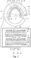
- Fig. 1 shows a sketch for illustrating an embodiment of the present invention for generating a first panoramic layer image 1 and a second panoramic layer image 2 of an imaged object 3, wherein the beam of X-rays 6, represented as a dotted line, that irradiates the jaw 4 of the patient's head 5 is generated by an X-ray source 7, wherein the object is irradiated along a main radiation direction 8 of the beam of the X-rays 6.
- the X-rays 6 then impact an X-ray detector 9, such as a CMOS detector, and are recorded by the latter.
- the X-ray detector 9 is for example continuously moved around the object 3, as indicated by arrow 10.
- the X-ray source 7 is mounted at opposite side and is accordingly moved along a circumferential path around the head 5 of the patient, as indicated by arrow 11.
- 500 2D X-ray projection images can be recorded in the course of a circumferential path 10.
- the main radiation direction 8 can for example be calculated as an average value of the individual directions of the beam of the X-rays 6.
- the individual 2D X-ray projection images are then used to calculate the first panoramic layer image 1, wherein the complete image information in relation to the active sensor area of the X-ray detector 9 is used.
- an available 3D model of the patient's head 5 can be analyzed, wherein the individual teeth 12 of the upper jaw and/or the lower jaw 4 are segmented, and optimized radiation directions optimized on the contact points are determined.
- a first contact point 13 between the front incisors 14 an overlap of the teeth is present in the first panoramic layer image 1, as indicated by the arrow 15.
- a first center optimized radiation direction 17 is then determined by a computer 16.
- a second optimized radiation direction 19 is determined on a second contact point 18.
- a third optimized radiation direction 21 is determined on a third contact point 20.
- the computer 16 calculates a selection of the partial areas of the 2D X-ray projection image, so that the second panoramic layer image 2 is calculated from the selected partial areas.
- the second panoramic layer image 2 in particular shows that the inter-dental contacts on the first contact point 13 between the front incisors 14 were opened on the second contact point 18 and on the third contact point 20, as indicated by the arrows 24, 25, and 26. The overlaps of the teeth on the contact points were reduced as much as possible.
- Data entry devices such as a keyboard 27 and a mouse 28, are connected to the computer 16.
- the user can employ the data entry device 27 and 28 by means of a cursor 30 to navigate within the panoramic layer images 1 and 2.
- a first virtual tool 31 the user can toggle back and forth between the rendering of the first panoramic layer image 1 and the second panoramic layer image 2.
- a second virtual tool 32 the user can use a magnifying glass function, wherein the user can use the magnifying glass to select a certain area in the first panoramic layer image 1, such as contact points 13, 18, and 20, wherein this area is rendered enlarged from the second panoramic layer image 2.
- Fig. 2 shows a sketch of a magnifying glass function of the second virtual tool 32 from Fig. 1 , wherein the user - in the first panoramic layer image 1 - selects a first overlapping area 40 on the position of the first contact point 13, which is rendered enlarged as section 41 from the second panoramic layer image 2.
- a second overlapping area 42 is correspondingly selected on the position of the second contact point 18 and rendered as a second section 43.
- a third overlapping area 44 is subsequently selected on the position of the third contact point 20 and rendered enlarged as a third section 45.
- the enlarged sections 41, 43, and 45 clearly show that the inter-dental contacts were opened on the contact points 13, 18, and 20, so that the overlaps within the first panoramic layer image 1 of teeth were reduced.
- Fig. 3 shows a sketch of a 2D X-ray projection image 51 of the X-ray detector 9, wherein a selected partial area 50, represented as a dotted line, is arranged on the left edge of the 2D X-ray projection image 51.
- the second panoramic layer image 2 is therefore calculated by only using the selected partial areas 50 of the individual 2D X-ray projection images 51.
- the main radiation directions would also be shifted as a result.
- other partial stripes can also be selected that can for example also be overlapping, in order to calculate other panoramic layer images.
- the 2D X-ray projection image 51 of the X-ray detector 9 could for example be split into 40 parallel partial stripes, so that 40 different panoramic layer images can be calculated.
- the user could then scroll through the various panoramic layer images, wherein the radiation direction is varied accordingly.
- the opening of the inter-dental contacts can then be graphically retraced.
- the user could then manually select an appropriate panoramic layer image with a sufficiently opened inter-dental contact.
- Fig. 4 shows a sketch of a further embodiment with a selected partial area 52 in the form of diagonally arranged partial stripe.
- the main radiation direction of the partial stripe 53 is therefore shifted to the right in relation to the initial main radiation direction of the 2D X-ray projection image 51, wherein in the lower area 54, the main radiation direction of the partial stripe 53 is shifted to the left in relation to the initial main radiation direction of the 2D X-ray projection image 51.
- Fig. 5 shows a sketch of a further embodiment, wherein the selected partial area comprises a first partial stripe 55 in the upper area 56 of the 2D X-ray projection image 51 and a second partial stripe 57 in the lower area 58 of the 2D X-ray projection image 51.
- the main radiation direction in the upper area of the 2D X-ray projection image 51 that is to say in the area of the upper jaw, is shifted to the left, wherein the main radiation direction in the lower area of the 2D X-ray projection image 51, in the area of the lower jaw, remains essentially unchanged in relation to an initial main radiation direction of the 2D X-ray projection image 51.
- a first width 59 of the first partial stripe 55 and a second width 60 of the second partial stripe 57 define the width of the focal layer 22 in the second calculated panoramic layer image 2.
- Fig. 6 shows a further embodiment on which the selected partial area is in the shape of a stripe 65 having a variable width, wherein in the center area 61 of the 2D X-ray projection image 51 a first width 62 is dimensioned greater than a second width 63 in the upper area of the 2D X-ray projection image 51 and a third width 64 in the lower area of the 2D X-ray projection image 51.
- the focal layer 22 in the second panoramic layer image 2 is narrower in the center area than in the upper or lower area.
- the teeth in the center area can be rendered with greater separation from foreign structures than objects in the upper and lower area.
- Fig. 7 shows a sketch of an X-ray detector 9, comprising a frame 70 and a sensor area 71, wherein the sensor area 71 comprises an unused and/or inactive area 72 and a used and/or active sensor area 73.
- the 2D X-ray projection image 51 is therefore recorded with the active sensor area 73.
- a partial area 50 shown as a dotted line, is selected from the image data of the recorded 2D X-ray projection image 51.
- the active sensor area 73 can also have the same size as the sensor area 71. There is consequently no inactive sensor area 72 on such an embodiment.
Landscapes
- Health & Medical Sciences (AREA)
- Engineering & Computer Science (AREA)
- Life Sciences & Earth Sciences (AREA)
- Medical Informatics (AREA)
- Physics & Mathematics (AREA)
- Radiology & Medical Imaging (AREA)
- Nuclear Medicine, Radiotherapy & Molecular Imaging (AREA)
- General Health & Medical Sciences (AREA)
- Veterinary Medicine (AREA)
- Public Health (AREA)
- Biomedical Technology (AREA)
- Animal Behavior & Ethology (AREA)
- Surgery (AREA)
- Molecular Biology (AREA)
- Biophysics (AREA)
- Heart & Thoracic Surgery (AREA)
- Pathology (AREA)
- High Energy & Nuclear Physics (AREA)
- Optics & Photonics (AREA)
- Theoretical Computer Science (AREA)
- General Physics & Mathematics (AREA)
- Computer Vision & Pattern Recognition (AREA)
- Human Computer Interaction (AREA)
- Dentistry (AREA)
- Oral & Maxillofacial Surgery (AREA)
- Quality & Reliability (AREA)
- Apparatus For Radiation Diagnosis (AREA)
- Non-Silver Salt Photosensitive Materials And Non-Silver Salt Photography (AREA)
Abstract
Description
- The invention relates to a device and a method for generating a panoramic layer image of an object to be imaged, wherein the object is imaged by projecting X-rays generated by an X-ray source through the object in a projection direction and recording said X-rays with an X-ray detector, wherein several 2D X-ray projection images are continuously recorded from various imaging directions while the X-ray source and the X-ray detector move around the object, wherein at least one panoramic layer image is calculated from the recorded 2D X-ray projection images by means of an algorithm.
- Several methods for generating panoramic layer images are known from the prior art.
-
WO 2015092119 A1 andUS 20150164446 A1 relates to generating digital dental panoramic layer images from multiple frame images acquired during a dental panoramic imaging scan from various scanning directions around a patient's head. The panoramic image is calculated by using information around the position and orientation of the X-ray source and the X-ray detector at particular points in time. -
DE 102008008733 A1 discloses a method for generating a virtual panoramic layer image from a 3D volume, wherein the object to be imaged is virtually irradiated with a virtual X-ray source and the virtually generated image is recorded by a virtual detector. Undesirable structures can be removed during virtual radiation. - A disadvantage of this method is that the panoramic image is corrected based on an elaborate procedure for taking unwanted structures into account that in particular requires a 3D volume to virtually irradiate the object as desired.
- Calculating a virtual panoramic layer image therefore requires a 3D volume from which the objects of interest are virtually irradiated. The resolution of virtual panoramic layer images is frequently lower than for classic panoramic layer images; additional artifacts can also occur. Preparing the 3D volume frequently requires a higher radiation dose.
-
DE 10016678 A1 discloses a method for irradiating an object, wherein the examined object is irradiated such that interfering, highly-absorbing objects, such as metal fillings, minimize the interference for imaging the opposing half of the jaw. -
EP 0 279 294 A1 discloses a dental X-ray diagnostic apparatus for preparing panoramic layer images of a patient's jaw. The specified method permits rendering a layer in the object, the center of which is normally the patient's jaw. The panoramic layer image is prepared by moving a radiation source-detector arrangement around an imaged object and by clocking the CCD detector lines with a frequency changed relative to the speed of motion in order to generate a layer image by blurring the portions lying outside of the focal layer. - A disadvantage of the specified method is that a correction of the panoramic layer image is frequently very elaborate or completely impossible with regard to unwanted overlaps.
- The object of the present invention is to provide a method for generating a panoramic layer image that in a straightforward manner can adjust the parameters and therefore the image in order to avoid repeated imaging and to improve diagnostic capabilities.
- The invention relates to a device and a method for generating a panoramic layer image of an object to be imaged, by employing a 2D panoramic X-ray device, wherein the object is imaged by projecting X-rays generated by an X-ray source through the object in an radiation direction and recording said X-rays with an X-ray detector, wherein several 2D X-ray projection images are continuously recorded from various imaging directions while the X-ray source and the X-ray detector move around the object, wherein at least one panoramic layer image is calculated from the recorded 2D X-ray projection images by means of a reconstruction method. The panoramic layer image is calculated by selecting at least one partial area of at least two 2D X-ray projection images in relation to an active sensor area and using these for the calculation.
- A panoramic layer image is a two-dimensional X-ray image of the upper jaw and/or the lower jaw that is recorded with a 2D panoramic X-ray device. The panoramic X-ray device can for example comprise an imaging unit with an X-ray detector, wherein the latter describes a movement around the patient's head during the imaging process. Synchronously on the opposite side thereto, the X-ray source moves around the patient's head. The X-ray source is designed to radiate a spatially restricted beam of X-rays that for example expands from an approximate width of 0.25 mm to an approximate width of 3 mm at the X-ray detector. This beam irradiates the jaw sections of the object, causing the 2D X-ray projection images of the different jaw sections of the entire jaw to be recorded frame by frame on the X-ray detector. A reconstruction method is then used to calculate a panoramic layer image from the recorded 2D X-ray projection images by assembling or computationally modeling the individual 2D X-ray projection images. The process of assembling the individual 2D X-ray projection images generates a focal layer of the panoramic layer images, said focal layer clearly showing anatomic structures located therein. This focus layer generally comprises the principal anatomic structures of the upper jaw and/or the lower jaw, such as teeth, tooth roots, and the jaw bones. The position/shape of the focal layer is determined by the path observed by the X-ray detector and the X-ray source in relation to the imaged object. The anatomic structures not located in the focal layer generate a shadow and are blurred out. The location of the focal layer is therefore determined by this path and the movements observed by the X-ray detector and by the X-ray source relative to the scanned object, wherein the width of the focal layers is additionally determined by the width of the irradiated area of the X-ray detector and/or by the width of the particular 2D X-ray projection images. A narrower width of the X-ray detector results in a wider focal layer and a wider X-ray detector results in a narrower focal layer while at the same time adjusting the beam to the X-ray detector width.
- The present method therefore does not only calculate the panoramic layer image by using the complete 2D X-ray projection images in relation to the active sensor size, but also by merely selecting and using at least a partial area of these 2D X-ray projection images for the calculation. A smaller, arbitrarily shaped X-ray detector is therefore essentially simulated by selecting the at least one partial area.
- An advantage of this method is that selecting the at least one partial area of the individual 2D X-ray projection images allows the width of the focal layer and also the radiation angle to be influenced by predetermined criteria. The individual partial areas of the 2D X-ray projection images can therefore be selected such that unfavorable overlaps within the focal layers of the panoramic layer image, for example of teeth and/or tooth crowns, are reduced and the principal anatomic structures, such as teeth and tooth roots, are rendered better.
- Yet another advantage of the method is that the method is executed without the need for novel devices, but can instead be based on a conventional 2D panoramic X-ray device, wherein only the software is used to select the at least one partial area of the recorded 2D X-ray projection images in order to calculate a second panoramic layer image.
- Yet another advantage of the method is that limiting the projection information used to reconstruct the panoramic layer image permits opening the inter-dental contacts, thus improving a dentist's diagnostic capabilities and reducing the number of repeat imaging procedures.
- The X-ray detector can for example comprise a CMOS detector or a directly-converting detector having a width from 1 cm to 4 cm.
- 300 to 5000 2D X-ray projection images can for example be recorded while the X-ray detector moves around the object. This for example involves recording 50-1000 2D X-ray projection images per second.
- The size of the partial area can advantageously comprise a maximum of 80% of the particular 2D X-ray projection image.
- Relatively large partial areas of the 2D X-ray projection images are selected as a result. The at least one partial area can then comprise various shapes, such as an individual vertical stripe, a diagonally oriented stripe, or a stripe of variable width. When several partial areas are used, these can be positioned arbitrarily to each other, for example with a horizontal offset. Several partial areas of an individual 2D X-ray projection image can for example be several parallel, vertical stripes.
- Selecting a smaller partial area on a side of the particular 2D X-ray projection image therefore increases the width of the focal layer and accordingly shifts a main radiation direction. A partial area with a variable width also allows the width of the focal layer to be locally varied within the panoramic layer image.
- Advantageously, the size of the at least one partial area can comprise at most 40% of the active area of the particular 2D X-ray projection image.
- As a result, relatively small partial areas are selected and used for calculating the panoramic layer image, thus changing or manipulating the panoramic layer image with greater effect.
- Advantageously, a weighting function can be applied on the image data of the at least one selected partial area, wherein the weighted partial areas are used for calculating the panoramic layer image.
- A Gauss function can for example be used as the weighting function. Image data in the center of the selected partial areas are then assigned a higher weight than the perimeter areas.
- Advantageously, the partial area can be a partial stripe having a fixed width or a variable width.
- By selecting a vertical partial stripe, each of the 2D X-ray projection images can for example be split into 40 partial stripes that can also be arranged with an overlap, so that for each individual partial stripe an individual panoramic layer image can be calculated that has a deviating main radiation direction. Consequently, for example 40 different panoramic layer images with variable main radiation directions can then be calculated from the same 2D X-ray projection images.
- For a partial stripe with a variable width, for example the width can be reduced in the upper and lower area of the partial stripe and widened in the center area of the partial stripe, so that the width of the focal layer in the center area of the two jaws - e.g. in the area of the occlusal surfaces - is reduced in the second panoramic layer image, thus showing in particular the teeth in focus. The width of the focal layer is larger in the upper and lower area of the panoramic layer image so that objects arranged in the focal layer - such as the jaw bone and the tooth roots - are shown with less separation since other adjacent anatomical structures are also located within the focal layer, thus becoming more readily identifiable.
- Advantageously, the at least one partial area can be selected manually by a user or automatically by employing an algorithm.
- A user can therefore manually select the at least one partial area. The user can for example directly determine the at least one partial area, wherein then automatically based on these inputs, the corresponding partial areas within the 2D X-ray projection images are automatically selected by the computer. The user can also define a desired main radiation direction, for example in a contact area between two teeth, wherein the partial areas required for the reconstruction are then automatically determined by the computer in order to adjust the main radiation direction.
- The partial areas can also be selected fully automatically, wherein the position/shape and width of the focal layer and the arrangement of the main radiation directions on the contact points between the individual teeth are determined automatically based on a reference head or based on prior knowledge, such as a 3D model of the upper and/or lower jaw, wherein the partial areas are then determined based on these inputs in order to calculate the desired panoramic layer image.
- Advantageously, the selection of at least one partial area within the 2D X-ray projection images allows a width of a focal layer of the calculated panoramic layer image to be changed.
- This influences the width of the focal layer by selecting the partial areas.
- Advantageously, selecting at least one partial area within the 2D X-ray projection images allows the adjustment of at least one main radiation direction of the particular 2D X-ray projection image and therefore an adjustment of a main radiation direction to an associated position of the focal layer of the calculated panoramic layer image.
- Selecting the at least one partial area then adjusts a main radiation direction of the calculated panoramic layer image. For example, if a partial stripe is selected on the left of the 2D X-ray projection images of the contact point between two molars and a panoramic layer image is calculated from the selected partial stripe, the main radiation direction on the contact location between the two molars is also shifted. In this manner, for example an opening can occur on the particular inter-dental contact on the contact points between the two molars, thus reducing an overlap of the molars in the panoramic layer image as much as possible.
- Advantageously, the adjustment of the main radiation direction of the particular 2D X-ray projection images and therefore of the main radiation direction of the focal layer and/or the adjustment of the width of the focal layer can be made as a function of the anatomical structures of the object to be imaged.
- The main radiation direction and the width of the focal layers are therefore adjusted as a function of the anatomical structures of the object to be imaged, that is to say the two jaws. For example, a 3D model from an optical 3D image of the two jaws can be relied on for this purpose, wherein the width of the focal layer and the main radiation directions can be determined on the contact points between the teeth as a function of the shape and extent of the upper and/or lower jaw.
- Advantageously, the adjustment of the main radiation direction of the particular 2D X-ray projection images and therefore the adjustment of the main radiation direction of the focal layer can be made toward the opening of inter-dental contacts, wherein contact point between the teeth are determined and pre-defined and an appropriate center optimized radiation direction is determined for the particular position of the focal layer, such that the teeth have the lowest possible, or no, overlaps in the particular contact point within the calculated panoramic layer image.
- Certain optimized radiation directions are thereby determined for the individual contact points between the teeth, and, as a function thereof, a second panoramic layer image is calculated, wherein the overlaps of the teeth at the contact points are minimized as much as possible.
- Advantageously, a first panoramic layer image can be calculated from the individual 2D X-ray projection images, wherein the complete image information of the complete active sensor area of the 2D X-ray projection images is used for the calculation, wherein a second panoramic layer image is calculated from the selected partial areas of the 2D X-ray projection images.
- The first panoramic layer image is thereby calculated from the complete 2D X-ray projection images, wherein the second panoramic layer image is calculated from the selected partial areas.
- Advantageously, a difference between an actual radiation direction of the first panoramic layer image and a optimised radiation direction of the second panoramic layer images can be used to automatically determine tooth misalignments and to highlight these in a graphical rendering of the first and/or second panoramic layer image.
- The difference between the actual radiation direction of the panoramic layer image and the optimised radiation direction of the second panoramic layer image is thereby indicated, so that it becomes evident at what locations the radiation direction was changed to reduce overlaps between the teeth at the contact points.
- The optimized radiation direction on the inter-dental contacts and/or the contact points between the individual teeth can be determined manually by the user or automatically by a computer, wherein the individual teeth can be segmented and the particular contact point can be analyzed. This involves determining an optimized radiation direction under the scope of the radiation beam of the X-rays of the individual 2D X-ray projection images that results in the lowest possible overlap of the teeth along the contact points in a second calculated panoramic layer image.
- Advantageously, a user can employ a control apparatus to toggle between a graphical rendering of the first panoramic layer image and the second panoramic layer image.
- The user can thereby arbitrarily toggle between the first panoramic layer image and the second panoramic layer image. The first panoramic layer image and the second panoramic layer image can also be displayed simultaneously with a display apparatus.
- Advantageously, a user can use a control apparatus to select an area in a graphical rendering of the first panoramic layer image, wherein a magnified rendering of this area from the second panoramic layer image is superimposed in the manner of a magnifying glass function.
- The user can thereby select a certain area in the first panoramic layer image, such as a certain contact point between two teeth, so that this area is superimposed in the manner of a magnifying glass function from the second panoramic layer image with opened inter-dental contacts. In this manner, the user is then shown the conventional panoramic layer image, with the additional function that an opening of the inter-dental contact is permitted on the contact points with overlaps.
- The invention further relates to an apparatus for executing the aforementioned method, comprising a computer, the X-ray source, the X-ray detector, a support arm for moving the X-ray source and the X-ray detector around the object to be imaged. The X-ray detector in this case has a width of at least 5 mm, wherein the computer employs a selection algorithm to select at least one partial area within the 2D X-ray projection image and then employs a calculation algorithm to calculate the panoramic layer image.
- The apparatus to execute the aforementioned method therefore comprises the elements of a conventional 2D panoramic X-ray apparatus and a computer. The X-ray detector can also have a width between 5 mm and 40 mm, so that the location of the partial areas can be selected with greater flexibility.
- An advantage of the apparatus is that only at least two conventional, corresponding 2D X-ray projection images of a panoramic layer image and a computer are sufficient to execute the present method. The software in this case only performs the selection of the at least one partial area in the 2D X-ray projection images and the calculation of the second panoramic layer image.
- The invention is explained based on the drawings. These show in
- Fig. 1
- a sketch for illustrating an embodiment of the present method, in
- Fig. 2
- a sketch of a magnifying glass function of the second virtual tool, in
- Fig. 3
- a sketch of a 2D X-ray projection image with a partial stripe, in
- Fig. 4
- a sketch of 2D X-ray projection image with a diagonal partial stripe, in
- Fig. 5
- a sketch of a 2D X-ray projection image with two partial stripes, in
- Fig. 6
- a sketch of a 2D X-ray projection image with a partial stripe having a variable width, in
- Fig. 7
- a sketch of an X-ray detector comprising a frame and a sensor area.
-
Fig. 1 shows a sketch for illustrating an embodiment of the present invention for generating a firstpanoramic layer image 1 and a secondpanoramic layer image 2 of an imagedobject 3, wherein the beam ofX-rays 6, represented as a dotted line, that irradiates thejaw 4 of the patient'shead 5 is generated by anX-ray source 7, wherein the object is irradiated along amain radiation direction 8 of the beam of theX-rays 6. TheX-rays 6 then impact anX-ray detector 9, such as a CMOS detector, and are recorded by the latter. During the imaging procedure, theX-ray detector 9 is for example continuously moved around theobject 3, as indicated byarrow 10. This involves recording individual 2D X-ray projection images from different imaging directions and/or main radiation directions. Synchronously to theX-ray detector 9, theX-ray source 7 is mounted at opposite side and is accordingly moved along a circumferential path around thehead 5 of the patient, as indicated byarrow 11. - For example 500 2D X-ray projection images can be recorded in the course of a
circumferential path 10. Themain radiation direction 8 can for example be calculated as an average value of the individual directions of the beam of theX-rays 6. The individual 2D X-ray projection images are then used to calculate the firstpanoramic layer image 1, wherein the complete image information in relation to the active sensor area of theX-ray detector 9 is used. - In order to open overlapping inter-dental contacts, an available 3D model of the patient's
head 5 can be analyzed, wherein theindividual teeth 12 of the upper jaw and/or thelower jaw 4 are segmented, and optimized radiation directions optimized on the contact points are determined. On afirst contact point 13 between thefront incisors 14, an overlap of the teeth is present in the firstpanoramic layer image 1, as indicated by thearrow 15. A first center optimizedradiation direction 17 is then determined by acomputer 16. A second optimizedradiation direction 19 is determined on asecond contact point 18. A third optimizedradiation direction 21 is determined on athird contact point 20. On the basis of the specified optimizedradiation directions focal layer 22, thecomputer 16 then calculates a selection of the partial areas of the 2D X-ray projection image, so that the secondpanoramic layer image 2 is calculated from the selected partial areas. The secondpanoramic layer image 2 in particular shows that the inter-dental contacts on thefirst contact point 13 between thefront incisors 14 were opened on thesecond contact point 18 and on thethird contact point 20, as indicated by thearrows keyboard 27 and amouse 28, are connected to thecomputer 16. Adisplay apparatus 29, such as a monitor, is also connected to thecomputer 16 in order to graphically render the first calculatedpanoramic layer image 1 and the secondpanoramic layer image 2. The user can employ thedata entry device cursor 30 to navigate within thepanoramic layer images virtual tool 31, the user can toggle back and forth between the rendering of the firstpanoramic layer image 1 and the secondpanoramic layer image 2. By employing a second virtual tool 32, the user can use a magnifying glass function, wherein the user can use the magnifying glass to select a certain area in the firstpanoramic layer image 1, such as contact points 13, 18, and 20, wherein this area is rendered enlarged from the secondpanoramic layer image 2. -
Fig. 2 shows a sketch of a magnifying glass function of the second virtual tool 32 fromFig. 1 , wherein the user - in the first panoramic layer image 1 - selects a first overlapping area 40 on the position of thefirst contact point 13, which is rendered enlarged assection 41 from the secondpanoramic layer image 2. A second overlapping area 42 is correspondingly selected on the position of thesecond contact point 18 and rendered as asecond section 43. A third overlappingarea 44 is subsequently selected on the position of thethird contact point 20 and rendered enlarged as athird section 45. Theenlarged sections panoramic layer image 1 of teeth were reduced. -
Fig. 3 shows a sketch of a 2DX-ray projection image 51 of theX-ray detector 9, wherein a selectedpartial area 50, represented as a dotted line, is arranged on the left edge of the 2DX-ray projection image 51. The secondpanoramic layer image 2 is therefore calculated by only using the selectedpartial areas 50 of the individual 2DX-ray projection images 51. The main radiation directions would also be shifted as a result. Within the 2DX-ray projection image 51 of theX-ray detector 9, other partial stripes can also be selected that can for example also be overlapping, in order to calculate other panoramic layer images. The 2DX-ray projection image 51 of theX-ray detector 9 could for example be split into 40 parallel partial stripes, so that 40 different panoramic layer images can be calculated. In an embodiment, the user could then scroll through the various panoramic layer images, wherein the radiation direction is varied accordingly. In this manner, the opening of the inter-dental contacts can then be graphically retraced. The user could then manually select an appropriate panoramic layer image with a sufficiently opened inter-dental contact. -
Fig. 4 shows a sketch of a further embodiment with a selectedpartial area 52 in the form of diagonally arranged partial stripe. In theupper area 53 of the partial stripe, the main radiation direction of thepartial stripe 53 is therefore shifted to the right in relation to the initial main radiation direction of the 2DX-ray projection image 51, wherein in thelower area 54, the main radiation direction of thepartial stripe 53 is shifted to the left in relation to the initial main radiation direction of the 2DX-ray projection image 51. This simulates a diagonally arranged X-ray detector. -
Fig. 5 shows a sketch of a further embodiment, wherein the selected partial area comprises a firstpartial stripe 55 in theupper area 56 of the 2DX-ray projection image 51 and a secondpartial stripe 57 in thelower area 58 of the 2DX-ray projection image 51. In this manner, the main radiation direction in the upper area of the 2DX-ray projection image 51, that is to say in the area of the upper jaw, is shifted to the left, wherein the main radiation direction in the lower area of the 2DX-ray projection image 51, in the area of the lower jaw, remains essentially unchanged in relation to an initial main radiation direction of the 2DX-ray projection image 51. Afirst width 59 of the firstpartial stripe 55 and asecond width 60 of the secondpartial stripe 57 define the width of thefocal layer 22 in the second calculatedpanoramic layer image 2. -
Fig. 6 shows a further embodiment on which the selected partial area is in the shape of astripe 65 having a variable width, wherein in thecenter area 61 of the 2D X-ray projection image 51 afirst width 62 is dimensioned greater than asecond width 63 in the upper area of the 2DX-ray projection image 51 and athird width 64 in the lower area of the 2DX-ray projection image 51. As a result, thefocal layer 22 in the secondpanoramic layer image 2 is narrower in the center area than in the upper or lower area. As a result, the teeth in the center area can be rendered with greater separation from foreign structures than objects in the upper and lower area. -
Fig. 7 shows a sketch of anX-ray detector 9, comprising aframe 70 and asensor area 71, wherein thesensor area 71 comprises an unused and/orinactive area 72 and a used and/oractive sensor area 73. The 2DX-ray projection image 51 is therefore recorded with theactive sensor area 73. Apartial area 50, shown as a dotted line, is selected from the image data of the recorded 2DX-ray projection image 51. Theactive sensor area 73 can also have the same size as thesensor area 71. There is consequently noinactive sensor area 72 on such an embodiment. -
- 1
- first panoramic layer image
- 2
- second panoramic layer image
- 3
- imaged object
- 4
- jaw
- 5
- patient's head
- 6
- radiation beam of X-rays
- 7
- X-ray source
- 8
- radiation direction of the radiation beam
- 9
- X-ray detector
- 10
- arrow for the circumferential path of the X-ray detector
- 11
- arrow for the circumferential path of the X-ray source
- 12
- individual teeth of the jaw
- 13
- first contact point of the incisors
- 14
- incisors
- 15
- arrow for rendering the overlap of the teeth
- 16
- computer
- 17
- first center optimized radiation direction
- 18
- second contact point of the incisors
- 19
- second optimized radiation direction
- 20
- third contact point of the incisors
- 21
- third optimized radiation direction
- 22
- width of the focal layer
- 23
- area of the molars
- 24
- arrow
- 25
- arrow
- 26
- arrow
- 27
- keyboard
- 28
- mouse
- 29
- display apparatus
- 30
- cursor
- 31
- first virtual tool
- 32
- second virtual tool
- 40
- first area
- 41
- enlarged section of the first area
- 42
- second area
- 43
- enlarged section of the second area
- 44
- third area
- 45
- enlarged section of the third area
- 50
- selected partial area
- 51
- 2D X-ray projection image
- 52
- selected partial area
- 53
- upper area of the partial stripe
- 54
- lower area of the partial stripe
- 55
- first partial stripe
- 56
- upper area of the 2D X-ray projection image
- 57
- second partial stripe
- 58
- lower area of the 2D X-ray projection image
- 59
- first width of the first partial stripe
- 60
- second width of the first partial stripe
- 61
- center area of the 2D X-ray projection image
- 62
- first width in the upper area of the 2D X-ray projection image
- 63
- second width in the upper area of the 2D X-ray projection image
- 64
- third width in the lower area of the 2D X-ray projection image
- 65
- stripe having a variable width
- 70
- frame
- 71
- sensor area
- 72
- unused and/or inactive sensor area
- 73
- used and/or active sensor area
Claims (15)
- Method for generating a panoramic layer image (1, 2) of an object (3) to be imaged, by employing a 2D panoramic X-ray device, wherein the object (3) is imaged by projecting X-rays (6) generated by an X-ray source (7) through the object (3) in a radiation direction (8) and recording said X-rays with an X-ray detector (9), wherein several 2D X-ray projection images are continuously recorded from various imaging directions while the X-ray source (7) and the X-ray detector (9) move around the object (3), wherein at least one panoramic layer image (2) is calculated from the recorded 2D X-ray projection images by means of a reconstruction method, characterized in that the panoramic layer image (2) is calculated by selecting and using at least one partial area (50, 52, 55, 57, 65) from at least two 2D X-ray projection images (51) in relation to an active sensor area (73).
- Method according to Claim 1, characterized in that the size of the at least one partial area (50, 52, 55, 57, 65) is no greater than 80% or no greater than 40% of the particular 2D X-ray projection image (51).
- Method according to Claim 1 or 2, characterized in that a weighting function is applied on the image data of the at least one selected partial area (50, 52, 55, 57, 65), wherein the weighted partial areas are used for calculating the panoramic layer image (2).
- Method according to any of Claims 1-3, characterized in that the at least one partial area is a partial stripe (50, 52, 55, 57, 65) having a fixed width (59, 60) or a variable width (62, 63, 64).
- Method according to any of Claims 1-4, characterized in that the at least one partial area (50, 52, 55, 57, 65) is predefined for all 2D X-ray projection images (51) with respect to its position in relation to the actively irradiated sensor area (73), with respect to its size, and with respect to its shape, or is variable for different 2D X-ray projection images (51).
- Method according to any of Claims 1-5, characterized in that the at least one partial area (50, 52, 55, 57, 65) is selected manually by the user or automatically by employing an algorithm.
- Method according to any of Claims 1-6, characterized in that the selection of the at least one partial area (50, 52, 55, 57, 65) within the 2D X-ray projection image (51) changes a width of a focal layer (22) of the calculated panoramic layer image (2).
- Method according to any of Claims 1-7, characterized in that the selection of the at least one partial area (50, 52, 55, 57, 65) within the 2D X-ray projection images (51) causes at least one main radiation direction (8) of the particular 2D X-ray projection image and thereby a main radiation direction to be adjusted to an associated local position of the focal layer (22) of the calculated panoramic layer image (2).
- Method according to Claim 7 or 8, characterized in that the adjustment of the main radiation direction (8) of the particular 2D X-ray projection images (51) is achieved by selecting the at least one partial area (50, 52, 55, 57, 65) and therefore the adjustment of the center local radiation direction of the focal layer (22) and/or the adjustment of the width of the focal layer (22) as a function of the imaged anatomical structures (4) of the object (3).
- Method according to Claim 9, characterized in that the adjustment of the main radiation direction (8) of the particular 2D X-ray projection images (51) is achieved by the selection of the partial areas (50, 52, 55, 57, 65) and thereby achieving the adjustment of the main radiation direction of the focal layer (22) to the opening of inter-dental contacts, wherein contact points (13, 18, 20) between the teeth (14) are determined and predefined and an appropriate center optimized radiation direction (17, 19, 21) is determined for the particular position of the focal layer (22), such that the teeth (14) have as little as possible, or no, overlaps in the particular contact area (13) within the calculated panoramic layer image (2).
- Method according to any of Claims 1-10, characterized in that a first panoramic layer image (1) is calculated from the individual 2D X-ray projection images (51), wherein the complete image information of the 2D X-ray projection images (51) is used for the calculation, wherein a second panoramic layer image (2) is calculated from the individually selected partial areas (50, 52, 55, 57, 65) of the 2D X-ray projection images (51).
- Method according to Claim 11, characterized in that a difference between an actual radiation direction (8) of the first panoramic layer image and an optimized radiation direction (17, 19, 21) of the second panoramic layer image (2) is used to automatically determine overlapping tooth regions and to graphically highlight the latter in a graphical rendering of the first and/or second panoramic layer image.
- Method according to Claim 11 or 12, characterized in that a user employs a control device (31) to toggle between a graphical rendering of the first panoramic layer image (1) and the second panoramic layer image (2).
- Method according to Claim 11 or 12, characterized in that a user employs a control device (32) to select an area (40, 42, 44) in a graphical rendering of the first panoramic layer image (1), wherein an enlarged rendering (41, 43, 45) of this area from the second panoramic layer image (2) is superimposed in the manner of a magnifying glass function.
- Apparatus for executing the method according to any of Claims 1-14, comprising a computer (16), the X-ray source (7), the X-ray detector (9), a support arm for moving the X-ray source (7) and the X-ray detector (9) around the imaged object (3), characterized in that the X-ray detector (9) has an actively irradiated sensor width between 5 mm and 40 mm, wherein the computer (16) employs a selection algorithm to select at least one partial area (50, 52, 55, 57, 65) of the 2D X-ray projection image and uses a calculation algorithm to calculate the panoramic layer image (2).
Priority Applications (6)
| Application Number | Priority Date | Filing Date | Title |
|---|---|---|---|
| FIEP19171428.6T FI3730057T3 (en) | 2019-04-26 | 2019-04-26 | Method and apparatus for generating a panoramic layer image |
| EP19171428.6A EP3730057B1 (en) | 2019-04-26 | 2019-04-26 | Method and apparatus for generating a panoramic layer image |
| JP2021540234A JP7532379B2 (en) | 2019-04-26 | 2020-04-23 | Method and apparatus for generating panoramic layered images - Patents.com |
| CN202080007289.3A CN113226187B (en) | 2019-04-26 | 2020-04-23 | Method and apparatus for generating panoramic layer image |
| US17/605,644 US12048576B2 (en) | 2019-04-26 | 2020-04-23 | Method and apparatus for generating a panoramic layer image |
| PCT/EP2020/061261 WO2020216812A1 (en) | 2019-04-26 | 2020-04-23 | Method and apparatus for generating a panoramic layer image |
Applications Claiming Priority (1)
| Application Number | Priority Date | Filing Date | Title |
|---|---|---|---|
| EP19171428.6A EP3730057B1 (en) | 2019-04-26 | 2019-04-26 | Method and apparatus for generating a panoramic layer image |
Publications (2)
| Publication Number | Publication Date |
|---|---|
| EP3730057A1 true EP3730057A1 (en) | 2020-10-28 |
| EP3730057B1 EP3730057B1 (en) | 2022-12-28 |
Family
ID=66290336
Family Applications (1)
| Application Number | Title | Priority Date | Filing Date |
|---|---|---|---|
| EP19171428.6A Active EP3730057B1 (en) | 2019-04-26 | 2019-04-26 | Method and apparatus for generating a panoramic layer image |
Country Status (6)
| Country | Link |
|---|---|
| US (1) | US12048576B2 (en) |
| EP (1) | EP3730057B1 (en) |
| JP (1) | JP7532379B2 (en) |
| CN (1) | CN113226187B (en) |
| FI (1) | FI3730057T3 (en) |
| WO (1) | WO2020216812A1 (en) |
Families Citing this family (2)
| Publication number | Priority date | Publication date | Assignee | Title |
|---|---|---|---|---|
| EP3711672B1 (en) * | 2019-03-22 | 2022-01-26 | Sirona Dental Systems GmbH | Method and device for producing a panoramic tomographic image of an object to be recorded |
| EP4246439A1 (en) * | 2022-03-17 | 2023-09-20 | 3Shape A/S | Generation of a three-dimensional representation of a dental object during scanning with a dental imaging device |
Citations (7)
| Publication number | Priority date | Publication date | Assignee | Title |
|---|---|---|---|---|
| EP0279294A1 (en) | 1987-02-16 | 1988-08-24 | Siemens Aktiengesellschaft | Diagnostic dental X-ray installation for carrying out a panoramic tomography of a patient's jaw |
| DE10016678A1 (en) | 2000-04-04 | 2001-10-18 | Sirona Dental Systems Gmbh | Method for irradiation of material in object containing materials with extremely different absorption properties by controlling projection position of irradiating beam |
| DE102008008733A1 (en) | 2008-02-12 | 2009-08-13 | Sirona Dental Systems Gmbh | Method for creating a tomogram |
| US20090310845A1 (en) * | 2005-10-21 | 2009-12-17 | Koichi Ogawa | Panoramic imaging apparatus and image processing method for panoramic imaging |
| US20150164446A1 (en) | 2013-12-18 | 2015-06-18 | Planmeca Oy | Apparatus and method for generating dental panoramic images |
| WO2015092119A1 (en) | 2013-12-18 | 2015-06-25 | Planmeca Oy | Generating dental panoramic images |
| US20180122106A1 (en) * | 2012-05-16 | 2018-05-03 | Vatech Co., Ltd. | Method and apparatus for providing panorama image data |
Family Cites Families (10)
| Publication number | Priority date | Publication date | Assignee | Title |
|---|---|---|---|---|
| JP3966425B2 (en) * | 1998-09-02 | 2007-08-29 | 株式会社モリタ製作所 | Local irradiation X-ray CT imaging system |
| WO2000057789A1 (en) * | 1999-03-25 | 2000-10-05 | Nihon University | Local irradiation x-ray ct imaging method and apparatus |
| JP4844886B2 (en) * | 2005-10-21 | 2011-12-28 | 株式会社 アクシオン・ジャパン | Panoramic image photographing apparatus and panoramic image photographing method |
| JP2008086659A (en) * | 2006-10-04 | 2008-04-17 | Axion Japan:Kk | Image processing method and panoramic image photographing device |
| JP6040502B2 (en) * | 2011-10-17 | 2016-12-07 | 朝日レントゲン工業株式会社 | Dental X-ray equipment |
| US10335098B2 (en) * | 2013-07-19 | 2019-07-02 | Axion Japan Co., Ltd. | Panoramic imaging apparatus and diagnostic imaging method in same apparatus |
| JP5881192B2 (en) | 2014-06-24 | 2016-03-09 | 学校法人日本大学 | Panoramic X-ray imaging apparatus and panoramic X-ray imaging method |
| KR102097564B1 (en) * | 2014-09-18 | 2020-04-06 | 주식회사 바텍 | Method and Apparatus for Forming an X-ray Image |
| US10049467B2 (en) * | 2015-03-18 | 2018-08-14 | Vatech Co., Ltd. | Apparatus and method for reconstructing medical image |
| EP3370618B1 (en) | 2015-11-03 | 2019-12-25 | Trophy | Dynamic image data treatment in dental imaging devices |
-
2019
- 2019-04-26 EP EP19171428.6A patent/EP3730057B1/en active Active
- 2019-04-26 FI FIEP19171428.6T patent/FI3730057T3/en active
-
2020
- 2020-04-23 CN CN202080007289.3A patent/CN113226187B/en active Active
- 2020-04-23 WO PCT/EP2020/061261 patent/WO2020216812A1/en not_active Ceased
- 2020-04-23 US US17/605,644 patent/US12048576B2/en active Active
- 2020-04-23 JP JP2021540234A patent/JP7532379B2/en active Active
Patent Citations (7)
| Publication number | Priority date | Publication date | Assignee | Title |
|---|---|---|---|---|
| EP0279294A1 (en) | 1987-02-16 | 1988-08-24 | Siemens Aktiengesellschaft | Diagnostic dental X-ray installation for carrying out a panoramic tomography of a patient's jaw |
| DE10016678A1 (en) | 2000-04-04 | 2001-10-18 | Sirona Dental Systems Gmbh | Method for irradiation of material in object containing materials with extremely different absorption properties by controlling projection position of irradiating beam |
| US20090310845A1 (en) * | 2005-10-21 | 2009-12-17 | Koichi Ogawa | Panoramic imaging apparatus and image processing method for panoramic imaging |
| DE102008008733A1 (en) | 2008-02-12 | 2009-08-13 | Sirona Dental Systems Gmbh | Method for creating a tomogram |
| US20180122106A1 (en) * | 2012-05-16 | 2018-05-03 | Vatech Co., Ltd. | Method and apparatus for providing panorama image data |
| US20150164446A1 (en) | 2013-12-18 | 2015-06-18 | Planmeca Oy | Apparatus and method for generating dental panoramic images |
| WO2015092119A1 (en) | 2013-12-18 | 2015-06-25 | Planmeca Oy | Generating dental panoramic images |
Also Published As
| Publication number | Publication date |
|---|---|
| WO2020216812A1 (en) | 2020-10-29 |
| EP3730057B1 (en) | 2022-12-28 |
| JP2022529555A (en) | 2022-06-23 |
| CN113226187A (en) | 2021-08-06 |
| US20220202382A1 (en) | 2022-06-30 |
| JP7532379B2 (en) | 2024-08-13 |
| FI3730057T3 (en) | 2023-03-28 |
| US12048576B2 (en) | 2024-07-30 |
| CN113226187B (en) | 2025-12-09 |
Similar Documents
| Publication | Publication Date | Title |
|---|---|---|
| CN108463170B (en) | X-ray image display apparatus and X-ray image display method | |
| US10610185B2 (en) | X-ray CT apparatus including processing circuitry to perform a metal-artifact reducing process | |
| KR101819257B1 (en) | X-ray tomogram imaging device | |
| JP5756790B2 (en) | X-ray equipment | |
| US8320522B2 (en) | Method for creating a tomographic image | |
| KR101603993B1 (en) | A Single Sensor Multi-Functional Dental Extra-Oral X-Ray Imaging System | |
| JP5711200B2 (en) | Panoramic X-ray tomography apparatus and image processing apparatus | |
| JP6040502B2 (en) | Dental X-ray equipment | |
| JP2008114064A (en) | Method and system for defining at least one acquisition and processing parameter in a tomosynthesis system | |
| JP5881192B2 (en) | Panoramic X-ray imaging apparatus and panoramic X-ray imaging method | |
| EP3461418B1 (en) | A method and a system for obtaining operating parameters for x ray data acquisition | |
| CN113164154B (en) | Method and device for generating a panoramic tomographic image of an object to be recorded | |
| US12048576B2 (en) | Method and apparatus for generating a panoramic layer image | |
| JP2019536605A (en) | Method for reconstructing 2D image from multiple X-ray images | |
| JP5681926B2 (en) | Medical X-ray equipment | |
| EP4606313A1 (en) | Method of generating a cephalometric image of a patient's head with reduced chatter marks | |
| JP6164521B2 (en) | X-ray equipment | |
| JP6299045B2 (en) | Image processing apparatus, image processing method, and X-ray imaging apparatus | |
| EP4331497A1 (en) | X-ray system for the production of dental panoramic images with several offset individual x-ray emitters | |
| JP5830752B2 (en) | X-ray CT imaging apparatus and image processing method thereof | |
| JP2013138803A (en) | X-ray ct imaging apparatus and image processing method therefor | |
| JP2021023606A (en) | Image processing device, x-ray diagnostic device and image processing device |
Legal Events
| Date | Code | Title | Description |
|---|---|---|---|
| PUAI | Public reference made under article 153(3) epc to a published international application that has entered the european phase |
Free format text: ORIGINAL CODE: 0009012 |
|
| STAA | Information on the status of an ep patent application or granted ep patent |
Free format text: STATUS: THE APPLICATION HAS BEEN PUBLISHED |
|
| AK | Designated contracting states |
Kind code of ref document: A1 Designated state(s): AL AT BE BG CH CY CZ DE DK EE ES FI FR GB GR HR HU IE IS IT LI LT LU LV MC MK MT NL NO PL PT RO RS SE SI SK SM TR |
|
| AX | Request for extension of the european patent |
Extension state: BA ME |
|
| STAA | Information on the status of an ep patent application or granted ep patent |
Free format text: STATUS: REQUEST FOR EXAMINATION WAS MADE |
|
| 17P | Request for examination filed |
Effective date: 20210426 |
|
| RBV | Designated contracting states (corrected) |
Designated state(s): AL AT BE BG CH CY CZ DE DK EE ES FI FR GB GR HR HU IE IS IT LI LT LU LV MC MK MT NL NO PL PT RO RS SE SI SK SM TR |
|
| GRAP | Despatch of communication of intention to grant a patent |
Free format text: ORIGINAL CODE: EPIDOSNIGR1 |
|
| STAA | Information on the status of an ep patent application or granted ep patent |
Free format text: STATUS: GRANT OF PATENT IS INTENDED |
|
| INTG | Intention to grant announced |
Effective date: 20220802 |
|
| GRAS | Grant fee paid |
Free format text: ORIGINAL CODE: EPIDOSNIGR3 |
|
| GRAA | (expected) grant |
Free format text: ORIGINAL CODE: 0009210 |
|
| STAA | Information on the status of an ep patent application or granted ep patent |
Free format text: STATUS: THE PATENT HAS BEEN GRANTED |
|
| AK | Designated contracting states |
Kind code of ref document: B1 Designated state(s): AL AT BE BG CH CY CZ DE DK EE ES FI FR GB GR HR HU IE IS IT LI LT LU LV MC MK MT NL NO PL PT RO RS SE SI SK SM TR |
|
| REG | Reference to a national code |
Ref country code: GB Ref legal event code: FG4D |
|
| REG | Reference to a national code |
Ref country code: CH Ref legal event code: EP |
|
| REG | Reference to a national code |
Ref country code: DE Ref legal event code: R096 Ref document number: 602019023580 Country of ref document: DE |
|
| REG | Reference to a national code |
Ref country code: AT Ref legal event code: REF Ref document number: 1539944 Country of ref document: AT Kind code of ref document: T Effective date: 20230115 |
|
| REG | Reference to a national code |
Ref country code: IE Ref legal event code: FG4D |
|
| REG | Reference to a national code |
Ref country code: LT Ref legal event code: MG9D |
|
| PG25 | Lapsed in a contracting state [announced via postgrant information from national office to epo] |
Ref country code: SE Free format text: LAPSE BECAUSE OF FAILURE TO SUBMIT A TRANSLATION OF THE DESCRIPTION OR TO PAY THE FEE WITHIN THE PRESCRIBED TIME-LIMIT Effective date: 20221228 Ref country code: NO Free format text: LAPSE BECAUSE OF FAILURE TO SUBMIT A TRANSLATION OF THE DESCRIPTION OR TO PAY THE FEE WITHIN THE PRESCRIBED TIME-LIMIT Effective date: 20230328 Ref country code: LT Free format text: LAPSE BECAUSE OF FAILURE TO SUBMIT A TRANSLATION OF THE DESCRIPTION OR TO PAY THE FEE WITHIN THE PRESCRIBED TIME-LIMIT Effective date: 20221228 |
|
| REG | Reference to a national code |
Ref country code: NL Ref legal event code: MP Effective date: 20221228 |
|
| REG | Reference to a national code |
Ref country code: AT Ref legal event code: MK05 Ref document number: 1539944 Country of ref document: AT Kind code of ref document: T Effective date: 20221228 |
|
| PG25 | Lapsed in a contracting state [announced via postgrant information from national office to epo] |
Ref country code: RS Free format text: LAPSE BECAUSE OF FAILURE TO SUBMIT A TRANSLATION OF THE DESCRIPTION OR TO PAY THE FEE WITHIN THE PRESCRIBED TIME-LIMIT Effective date: 20221228 Ref country code: LV Free format text: LAPSE BECAUSE OF FAILURE TO SUBMIT A TRANSLATION OF THE DESCRIPTION OR TO PAY THE FEE WITHIN THE PRESCRIBED TIME-LIMIT Effective date: 20221228 Ref country code: HR Free format text: LAPSE BECAUSE OF FAILURE TO SUBMIT A TRANSLATION OF THE DESCRIPTION OR TO PAY THE FEE WITHIN THE PRESCRIBED TIME-LIMIT Effective date: 20221228 Ref country code: GR Free format text: LAPSE BECAUSE OF FAILURE TO SUBMIT A TRANSLATION OF THE DESCRIPTION OR TO PAY THE FEE WITHIN THE PRESCRIBED TIME-LIMIT Effective date: 20230329 |
|
| PG25 | Lapsed in a contracting state [announced via postgrant information from national office to epo] |
Ref country code: NL Free format text: LAPSE BECAUSE OF FAILURE TO SUBMIT A TRANSLATION OF THE DESCRIPTION OR TO PAY THE FEE WITHIN THE PRESCRIBED TIME-LIMIT Effective date: 20221228 |
|
| PG25 | Lapsed in a contracting state [announced via postgrant information from national office to epo] |
Ref country code: SM Free format text: LAPSE BECAUSE OF FAILURE TO SUBMIT A TRANSLATION OF THE DESCRIPTION OR TO PAY THE FEE WITHIN THE PRESCRIBED TIME-LIMIT Effective date: 20221228 Ref country code: RO Free format text: LAPSE BECAUSE OF FAILURE TO SUBMIT A TRANSLATION OF THE DESCRIPTION OR TO PAY THE FEE WITHIN THE PRESCRIBED TIME-LIMIT Effective date: 20221228 Ref country code: PT Free format text: LAPSE BECAUSE OF FAILURE TO SUBMIT A TRANSLATION OF THE DESCRIPTION OR TO PAY THE FEE WITHIN THE PRESCRIBED TIME-LIMIT Effective date: 20230428 Ref country code: ES Free format text: LAPSE BECAUSE OF FAILURE TO SUBMIT A TRANSLATION OF THE DESCRIPTION OR TO PAY THE FEE WITHIN THE PRESCRIBED TIME-LIMIT Effective date: 20221228 Ref country code: EE Free format text: LAPSE BECAUSE OF FAILURE TO SUBMIT A TRANSLATION OF THE DESCRIPTION OR TO PAY THE FEE WITHIN THE PRESCRIBED TIME-LIMIT Effective date: 20221228 Ref country code: CZ Free format text: LAPSE BECAUSE OF FAILURE TO SUBMIT A TRANSLATION OF THE DESCRIPTION OR TO PAY THE FEE WITHIN THE PRESCRIBED TIME-LIMIT Effective date: 20221228 Ref country code: AT Free format text: LAPSE BECAUSE OF FAILURE TO SUBMIT A TRANSLATION OF THE DESCRIPTION OR TO PAY THE FEE WITHIN THE PRESCRIBED TIME-LIMIT Effective date: 20221228 |
|
| PG25 | Lapsed in a contracting state [announced via postgrant information from national office to epo] |
Ref country code: SK Free format text: LAPSE BECAUSE OF FAILURE TO SUBMIT A TRANSLATION OF THE DESCRIPTION OR TO PAY THE FEE WITHIN THE PRESCRIBED TIME-LIMIT Effective date: 20221228 Ref country code: PL Free format text: LAPSE BECAUSE OF FAILURE TO SUBMIT A TRANSLATION OF THE DESCRIPTION OR TO PAY THE FEE WITHIN THE PRESCRIBED TIME-LIMIT Effective date: 20221228 Ref country code: IS Free format text: LAPSE BECAUSE OF FAILURE TO SUBMIT A TRANSLATION OF THE DESCRIPTION OR TO PAY THE FEE WITHIN THE PRESCRIBED TIME-LIMIT Effective date: 20230428 Ref country code: AL Free format text: LAPSE BECAUSE OF FAILURE TO SUBMIT A TRANSLATION OF THE DESCRIPTION OR TO PAY THE FEE WITHIN THE PRESCRIBED TIME-LIMIT Effective date: 20221228 |
|
| REG | Reference to a national code |
Ref country code: DE Ref legal event code: R097 Ref document number: 602019023580 Country of ref document: DE |
|
| PG25 | Lapsed in a contracting state [announced via postgrant information from national office to epo] |
Ref country code: DK Free format text: LAPSE BECAUSE OF FAILURE TO SUBMIT A TRANSLATION OF THE DESCRIPTION OR TO PAY THE FEE WITHIN THE PRESCRIBED TIME-LIMIT Effective date: 20221228 |
|
| PLBE | No opposition filed within time limit |
Free format text: ORIGINAL CODE: 0009261 |
|
| STAA | Information on the status of an ep patent application or granted ep patent |
Free format text: STATUS: NO OPPOSITION FILED WITHIN TIME LIMIT |
|
| REG | Reference to a national code |
Ref country code: DE Ref legal event code: R079 Ref document number: 602019023580 Country of ref document: DE Free format text: PREVIOUS MAIN CLASS: A61B0006140000 Ipc: A61B0006510000 |
|
| REG | Reference to a national code |
Ref country code: CH Ref legal event code: PL |
|
| 26N | No opposition filed |
Effective date: 20230929 |
|
| GBPC | Gb: european patent ceased through non-payment of renewal fee |
Effective date: 20230426 |
|
| PG25 | Lapsed in a contracting state [announced via postgrant information from national office to epo] |
Ref country code: LU Free format text: LAPSE BECAUSE OF NON-PAYMENT OF DUE FEES Effective date: 20230426 |
|
| REG | Reference to a national code |
Ref country code: BE Ref legal event code: MM Effective date: 20230430 |
|
| PG25 | Lapsed in a contracting state [announced via postgrant information from national office to epo] |
Ref country code: MC Free format text: LAPSE BECAUSE OF FAILURE TO SUBMIT A TRANSLATION OF THE DESCRIPTION OR TO PAY THE FEE WITHIN THE PRESCRIBED TIME-LIMIT Effective date: 20221228 |
|
| PG25 | Lapsed in a contracting state [announced via postgrant information from national office to epo] |
Ref country code: GB Free format text: LAPSE BECAUSE OF NON-PAYMENT OF DUE FEES Effective date: 20230426 |
|
| PG25 | Lapsed in a contracting state [announced via postgrant information from national office to epo] |
Ref country code: SI Free format text: LAPSE BECAUSE OF FAILURE TO SUBMIT A TRANSLATION OF THE DESCRIPTION OR TO PAY THE FEE WITHIN THE PRESCRIBED TIME-LIMIT Effective date: 20221228 Ref country code: MC Free format text: LAPSE BECAUSE OF FAILURE TO SUBMIT A TRANSLATION OF THE DESCRIPTION OR TO PAY THE FEE WITHIN THE PRESCRIBED TIME-LIMIT Effective date: 20221228 Ref country code: LI Free format text: LAPSE BECAUSE OF NON-PAYMENT OF DUE FEES Effective date: 20230430 Ref country code: GB Free format text: LAPSE BECAUSE OF NON-PAYMENT OF DUE FEES Effective date: 20230426 Ref country code: CH Free format text: LAPSE BECAUSE OF NON-PAYMENT OF DUE FEES Effective date: 20230430 |
|
| REG | Reference to a national code |
Ref country code: IE Ref legal event code: MM4A |
|
| PG25 | Lapsed in a contracting state [announced via postgrant information from national office to epo] |
Ref country code: BE Free format text: LAPSE BECAUSE OF NON-PAYMENT OF DUE FEES Effective date: 20230430 |
|
| PG25 | Lapsed in a contracting state [announced via postgrant information from national office to epo] |
Ref country code: IE Free format text: LAPSE BECAUSE OF NON-PAYMENT OF DUE FEES Effective date: 20230426 |
|
| PG25 | Lapsed in a contracting state [announced via postgrant information from national office to epo] |
Ref country code: IE Free format text: LAPSE BECAUSE OF NON-PAYMENT OF DUE FEES Effective date: 20230426 |
|
| PG25 | Lapsed in a contracting state [announced via postgrant information from national office to epo] |
Ref country code: BG Free format text: LAPSE BECAUSE OF FAILURE TO SUBMIT A TRANSLATION OF THE DESCRIPTION OR TO PAY THE FEE WITHIN THE PRESCRIBED TIME-LIMIT Effective date: 20221228 |
|
| P01 | Opt-out of the competence of the unified patent court (upc) registered |
Free format text: CASE NUMBER: UPC_APP_413290/2023 Effective date: 20230509 |
|
| PG25 | Lapsed in a contracting state [announced via postgrant information from national office to epo] |
Ref country code: BG Free format text: LAPSE BECAUSE OF FAILURE TO SUBMIT A TRANSLATION OF THE DESCRIPTION OR TO PAY THE FEE WITHIN THE PRESCRIBED TIME-LIMIT Effective date: 20221228 |
|
| PGFP | Annual fee paid to national office [announced via postgrant information from national office to epo] |
Ref country code: FI Payment date: 20250319 Year of fee payment: 7 |
|
| PGFP | Annual fee paid to national office [announced via postgrant information from national office to epo] |
Ref country code: DE Payment date: 20250319 Year of fee payment: 7 |
|
| PG25 | Lapsed in a contracting state [announced via postgrant information from national office to epo] |
Ref country code: CY Free format text: LAPSE BECAUSE OF FAILURE TO SUBMIT A TRANSLATION OF THE DESCRIPTION OR TO PAY THE FEE WITHIN THE PRESCRIBED TIME-LIMIT; INVALID AB INITIO Effective date: 20190426 |
|
| PG25 | Lapsed in a contracting state [announced via postgrant information from national office to epo] |
Ref country code: HU Free format text: LAPSE BECAUSE OF FAILURE TO SUBMIT A TRANSLATION OF THE DESCRIPTION OR TO PAY THE FEE WITHIN THE PRESCRIBED TIME-LIMIT; INVALID AB INITIO Effective date: 20190426 |
|
| PG25 | Lapsed in a contracting state [announced via postgrant information from national office to epo] |
Ref country code: TR Free format text: LAPSE BECAUSE OF FAILURE TO SUBMIT A TRANSLATION OF THE DESCRIPTION OR TO PAY THE FEE WITHIN THE PRESCRIBED TIME-LIMIT Effective date: 20221228 |
|
| PGFP | Annual fee paid to national office [announced via postgrant information from national office to epo] |
Ref country code: IT Payment date: 20260319 Year of fee payment: 8 |
|
| PGFP | Annual fee paid to national office [announced via postgrant information from national office to epo] |
Ref country code: FR Payment date: 20260320 Year of fee payment: 8 |