EP3730047A1 - Bidirectional sensor circuit - Google Patents
Bidirectional sensor circuit Download PDFInfo
- Publication number
- EP3730047A1 EP3730047A1 EP18890563.2A EP18890563A EP3730047A1 EP 3730047 A1 EP3730047 A1 EP 3730047A1 EP 18890563 A EP18890563 A EP 18890563A EP 3730047 A1 EP3730047 A1 EP 3730047A1
- Authority
- EP
- European Patent Office
- Prior art keywords
- terminal
- impedance
- diode
- inverting input
- operational amplifier
- Prior art date
- Legal status (The legal status is an assumption and is not a legal conclusion. Google has not performed a legal analysis and makes no representation as to the accuracy of the status listed.)
- Granted
Links
Images







Classifications
-
- G—PHYSICS
- G01—MEASURING; TESTING
- G01R—MEASURING ELECTRIC VARIABLES; MEASURING MAGNETIC VARIABLES
- G01R19/00—Arrangements for measuring currents or voltages or for indicating presence or sign thereof
- G01R19/0023—Measuring currents or voltages from sources with high internal resistance by means of measuring circuits with high input impedance, e.g. OP-amplifiers
-
- A—HUMAN NECESSITIES
- A61—MEDICAL OR VETERINARY SCIENCE; HYGIENE
- A61B—DIAGNOSIS; SURGERY; IDENTIFICATION
- A61B5/00—Measuring for diagnostic purposes; Identification of persons
- A61B5/72—Signal processing specially adapted for physiological signals or for diagnostic purposes
- A61B5/7225—Details of analogue processing, e.g. isolation amplifier, gain or sensitivity adjustment, filtering, baseline or drift compensation
-
- G—PHYSICS
- G01—MEASURING; TESTING
- G01R—MEASURING ELECTRIC VARIABLES; MEASURING MAGNETIC VARIABLES
- G01R1/00—Details of instruments or arrangements of the types included in groups G01R5/00 - G01R13/00 and G01R31/00
- G01R1/30—Structural combination of electric measuring instruments with basic electronic circuits, e.g. with amplifier
-
- H—ELECTRICITY
- H03—ELECTRONIC CIRCUITRY
- H03F—AMPLIFIERS
- H03F3/00—Amplifiers with only discharge tubes or only semiconductor devices as amplifying elements
- H03F3/45—Differential amplifiers
- H03F3/45071—Differential amplifiers with semiconductor devices only
- H03F3/45076—Differential amplifiers with semiconductor devices only characterised by the way of implementation of the active amplifying circuit in the differential amplifier
- H03F3/45475—Differential amplifiers with semiconductor devices only characterised by the way of implementation of the active amplifying circuit in the differential amplifier using IC blocks as the active amplifying circuit
Definitions
- the current invention relates to bi-directional current sensors using operational amplifiers and ground reference decoupling circuits.
- the invention is related, in particular, to the use of precision rectifier circuits with operational amplifiers for the detection of changes in the current of an impedance.
- a Hall effect voltage sensor works well at low frequencies, but as the frequency increases, the inductor used causes an inductive reverse voltage that lowers the accuracy of the sensor, known as offset voltage and displacement temperature for which compensation is required, in the case of the present invention the sensor works independently from the magnetic force.
- circuits used for sensing the current or voltage connect the impedance to be measured between the target ground and the reference ground, which becomes problematic when the electronic components change the ground reference and move with different values and current and voltage polarities.
- circuits such as precision full-wave rectifiers which have the function to rectify a signal, in general alternating with an amplitude generally around the order of millivolts where the voltage drop in the diodes of the traditional rectifier circuit becomes an important variable.
- these circuits do not have an impedance connected between the positive and negative inputs of the operational amplifiers, which allows sensing of a load impedance of interest that is configured in such a way that the voltage output is proportional to the current on the impedance between the inverting and non-inverting input of the operational amplifiers.
- US6985774B2 which shows a system that controls the cardiovascular reflex through the modulation or control of a baroreceptor activation device, which is a device that, among other techniques, electrically stimulates baroreceptors in the carotid sinus, the aortic arch, the heart, the common carotid arteries, the subclavian arteries and/or the brachiocephalic artery. It is evident that, in the biomedical field, electrically isolated devices are needed to measure or induce currents on tissues in living beings, so this type of sensors are necessary and can find their space in the market.
- sensors are used to record the body's electrical signals. It is well known that this equipment needs to limit the current that is directed towards the body of a patient, so the solution of several circuits is to place protection impedances limiting the current to the body, which means that they do not refer to the same ground level, so the sensing and measurement in these types of equipment at the output stage are difficult.
- a bidirectional sensor circuit comprising: a sensing impedance with a first terminal and a second terminal; a first operational amplifier which non-inverting input is connected to the first terminal and its inverting input is connected to the second terminal; a second operational amplifier with the non-inverting input connected to the second terminal and its inverting input is connected to the first terminal; a first diode with the cathode connected to the inverting input of the first operational amplifier and which anode is connected to the output of the first operational amplifier; a second diode with the anode connected to the output of the first operational amplifier and to the cathode of the first diode; a variable impedance connected to the cathode of the first diode and the anode of the second diode; a fourth diode with the anode connected to the cathode of the second diode and to one end of the variable impedance; a third diode with the cathode connected to the inverting input of the second operational amplifier and the
- the output is located at the anodes of the diodes by the output of both operational amplifiers that are shorted.
- the sensing impedance is small so that alterations on the impedance of the load to be measured are not included in the measurement.
- the gains of the operational amplifiers could be adjusted by means of variable impedances and are adjusted in such a way that the output corresponds to the same exact value of the bidirectional current flowing at the load impedance.
- the current invention should not be confused with a precision full-wave rectifier like the one shown in FIG. 1 , unlike this rectifier, the current invention includes an impedance connected between the inverting and non-inverting inputs of the operational amplifiers, where the measurement is made.
- the gain of the amplifiers is adjustable, and it is configured in such a way that the voltage output is proportional to the current over the impedance between the negative and positive input of the operational amplifiers.
- a sensor is a device, module, or subsystem which purpose is to detect events or changes in the environment such as light, a force, vibrations, temperature, sound, a magnetic field, or electric current and sends information to other electronic components, usually a computer or processor.
- the sensing action is, for example, taking electrical changes in impedance and sending information in the form of modulated signals to another electronic component.
- the current invention is a bidirectional sensor circuit consisting of: a sensing impedance (1) with a first terminal (1a) and a second terminal (1b); a first operational amplifier (2) which non-inverting input is connected to the first terminal (1a) and its inverting input is connected to the second terminal (1b); a second operational amplifier (3) with the non-inverting input connected to the second terminal (1b) and its inverting input is connected to the first terminal (1a); a first diode (4) with the anode connected to the inverting input of the first operational amplifier (2) and which cathode is connected to the output of the first operational amplifier (2); a second diode (5) with the anode connected to the output of the first operational amplifier (2) and to the cathode of the first diode (4); a variable impedance (13) connected to the anode of the first diode (4) and to the cathode of the second diode (5); a fourth diode (7) with the cathode connected to
- the gain on the two operational amplifiers is adjusted so that the voltage output equals the same exact value of the current on the load impedance the sense impedance (1), and it is adjusted with the variable impedances (12) and (13) for a particular example of the invention they are variable impedances of any type.
- the circuit of a mesh between the sensing impedance (1) and the load impedance (14) the value of the current corresponds to an integer multiple of the voltage value at the first terminal (1a) of the sensing impedance (1).
- the bidirectional sensor circuit is characterized by the non-inverting input of the first operational amplifier (2) that is connected to the first terminal (1a) through an impedance (9) and its inverting input is connected to the second terminal (1b) through an impedance (11); the non-inverting input of the second operational amplifier (3) is connected to the second terminal (1b) through an impedance (10) and its inverting input is connected to the first terminal (1a) through an impedance (8); where operational amplifiers are powered with a positive voltage V + and a negative voltage V-.
- the bidirectional sensor circuit is connected to an alternating current source (15) in series with the load impedance (14), the other terminal of the load impedance (14) that is not connected to the alternating current source (15) connects to the first terminal (1a) of the sensing impedance (1), the free terminal of the alternating current source (15) connects to the second terminal (1b) of the sensing impedance (1), this allows laboratory tests to be carried out.
- the non-inverting input of the first operational amplifier (2) is connected to the first terminal (1a) through an impedance (9) and its inverting input is connected to the second terminal (1b) through an impedance (11);
- the non-inverting input of the second operational amplifier (3) is connected to the second terminal (1b) through an impedance (10) and its inverting input is connected to the first terminal (1a) through an impedance (8); and a positive voltage V+ and a negative voltage V- power the operational amplifiers.
- bidirectional sensor circuit is characterized by an alternating current source (15) connected in series with a load impedance (14) also connected to the first terminal (1a) with the second terminal (1b) connected to the free terminal of the alternating current source (15), to carry out laboratory tests.
- FIG. 6 shows another particular example of the invention, where the terminals (1a) and (1b) of the sensing impedance (1) of the bidirectional sensor circuit are connected to an instrumentation Wheatstone bridge (19).
- the instrumentation Wheatstone bridge (19) has: a first terminal (19a), a second terminal (19b), a third terminal (19c) and a fourth terminal (19d); a first impedance (19ac) connected to the first terminal (19a) and the third terminal (19c); a second impedance (19bc) connected to the second terminal (19b) and the third terminal (19c); a third impedance (19bd) connected to the second terminal (19b) and the fourth terminal (19d); an alternating current source (15) connected to the third terminal (19c) and the fourth terminal (19d); the first terminal (19a) connected to the second terminal (1b) of the sensing impedance (1); the second terminal (19b) connected to the first terminal (1a) of the sensing impedance (1); and a load impedance (14) is connected to the first terminal (19a) and the fourth terminal (19d).
- the non-inverting input of the first operational amplifier (2) is connected to the first terminal (1a) through an impedance (9) and its inverting input is connected to the second terminal (1b) through an impedance (11);
- the non-inverting input of the second operational amplifier (3) is connected to the second terminal (1b) through an impedance (10) and its inverting input is connected to the first terminal (1a) through an impedance (8); and a positive voltage V+ and a negative voltage V- power the operational amplifiers.
- It also includes an instrumentation Wheatstone bridge (19) connected to terminals (1a) and (1b) of the sensing impedance (1).
- the load impedance (14) corresponds to the impedance to be sensed in the circuit, in the case of a Wheatstone impedance bridge and for any particular example of the invention, this impedance is chosen from the group of variable impedances, photoresistors, thermoresistors, magnetic sensors, piezoelectric sensors, inductive sensors to measure a magnetic field, and electromagnetic transducers, among others, and combinations of the foregoing without being limited to this list.
- the alternating current input signal enters through the non-inverting input of the first operational amplifier (2), while the first diode (4) is open, the variable impedance (13) serves as the gain impedance, and the first operational amplifier (2) works in non-inverting amplifier mode, in this case the gain is calculated as is known by the value of the variable impedance (13) on the value of the impedance (11), the voltage over the impedance (1) is expanded and measured at the output of the diode (5).
- the positive current on the diode (6) keeps it closed and the second operational amplifier (3) is configured in voltage follower mode.
- the second terminal (1b) connected to the non-inverting input of the second operational amplifier (3) there is a negative voltage, which keeps the diode (7) open, so that at the output of the second operational amplifier (3) any voltage is perceived.
- the first operational amplifier (2) is configured in voltage follower mode, no voltage is perceived at the output of the diode (5) when receiving negative voltage on the first terminal (1a) connected to its non-inverting input makes the diode (5) open.
- the second amplifier (3) instead, has the diode (6) open so that the impedance (12) works as an amplification impedance, and then the second operational amplifier (3) is configured as a non-inverting amplifier with a positive voltage over its non-inverting input.
- this configuration maintains a positive voltage output.
- the amplification gain on the operational amplifiers (2) and (3) is adjusted in such a way that the voltage output matches the same value of the current over the load impedance, preferably the value of the variable impedance (13) is variable just like the variable impedance value (12), and the impedance value of (11) and (8) is the same as well.
- the designer adjusts the gain of the circuit at will by varying the values of the variable impedances (13) and (12).
- the sensing impedance (1) is, for example, at least one order of magnitude compared to the input impedance, so that the voltage measured over it is comparable to the voltage over the signal impedance at to measure.
- a reversed bidirectional sensor circuit comprises: a sensing impedance (1) with a first terminal (1a) and a second terminal (1b); a first operational amplifier (2) for which the non-inverting input is connected to the first terminal (1a) and its inverting input is connected to the second terminal (1b); a second operational amplifier (3) with the non-inverting input connected to the second terminal (1b) and its inverting input is connected to the first terminal (1a); a first diode (4) with the cathode connected to the inverting input of the first operational amplifier (2) and for which the anode is connected to the output of the first operational amplifier (2); a second diode (5) with the cathode connected to the output of the first operational amplifier (2) and to the anode of the first diode (4); a variable impedance (13) connected to the cathode of the first diode (4) and to the anode of the second diode (5); a fourth di
- an operational inverter circuit is a circuit that inverts the input voltage and employs amplification, for example, an operational amplifier configured with unit negative gain or any gain as decided.
- the non-inverting input of the first operational amplifier (2) is connected to the first terminal (1a) through an impedance (9) and its inverting input connects to the second terminal (1b) through an impedance (11);
- the non-inverting input of the second operational amplifier (3) is connected to the second terminal (1b) through an impedance (10) and its inverting input is connected to the first terminal (1a) through an impedance (8); and a positive voltage V+ and a negative voltage V- power the operational amplifiers.
- FIG. 10 another example of the invention, shows an instrumentation Wheatstone bridge (19) connected to terminals (1a) and (1b) of the sensing impedance (1).
- the inverted bidirectional sensor circuit where the non-inverting input of the first operational amplifier (2) is connected to the first terminal (1a) through an impedance (9) and its inverting input is connected to the second terminal (1b) through an impedance (11); the non-inverting input of the second operational amplifier (3) is connected to the second terminal (1b) through an impedance (10) and its inverting input is connected to the first terminal (1a) through an impedance (8); and a positive voltage V+ and a negative voltage V- power the operational amplifiers.
- It includes an instrumentation Wheatstone bridge (19) connected to terminals (1a) and (1b) of the sensing impedance (1).
- a circuit for sensing current changes on one or more transducers includes: a bidirectional sensor circuit (22); a digital analog converter (16) connected to the bidirectional sensor circuit (22); a control unit (17) connected to the digital analog converter (16); a signal generator (18) connected to the control unit (17); one or more transducers (20) connected to the output of the signal generator (18), and to the bidirectional sensor circuit (22); wherein the bidirectional sensor circuit (22) senses the current on the one or more transducers and sends a voltage that corresponds proportionally to the current on the one or more transducers (20).
- the bidirectional sensor circuit can modulate a signal (for example, from a signal generator), in which the bidirectional sensor circuit is connected to sense the signal, and it is also connected to a digital-analog converter, and a control unit, allowing modulation and control of the signal generator.
- a signal for example, from a signal generator
- the bidirectional sensor circuit is connected to sense the signal, and it is also connected to a digital-analog converter, and a control unit, allowing modulation and control of the signal generator.
- the anode of the second diode (5) is connected to the input of a digital-analog converter (16); and a control unit (17) is connected to the output of the digital-analog converter (16).
- control unit (17) is connected to a signal generator (18) connected to a transducer (20), the transducer (20) is connected to the first terminal (1a) of the sensing impedance (1); wherein the transducer (20) is the load impedance (14).
- the control unit (17) commands the signal generator (18) using feedback of the output signal of the digital-analog converter (16).
- the signal generator (18) is rather decoupled in impedance so as not to vary the load impedance (14).
Landscapes
- Engineering & Computer Science (AREA)
- Physics & Mathematics (AREA)
- Health & Medical Sciences (AREA)
- General Physics & Mathematics (AREA)
- Life Sciences & Earth Sciences (AREA)
- Power Engineering (AREA)
- Signal Processing (AREA)
- Pathology (AREA)
- Molecular Biology (AREA)
- Psychiatry (AREA)
- Computer Vision & Pattern Recognition (AREA)
- Biophysics (AREA)
- Artificial Intelligence (AREA)
- Biomedical Technology (AREA)
- Heart & Thoracic Surgery (AREA)
- Medical Informatics (AREA)
- Physiology (AREA)
- Surgery (AREA)
- Animal Behavior & Ethology (AREA)
- General Health & Medical Sciences (AREA)
- Public Health (AREA)
- Veterinary Medicine (AREA)
- Measurement Of Current Or Voltage (AREA)
- Amplifiers (AREA)
Abstract
Description
- The current invention relates to bi-directional current sensors using operational amplifiers and ground reference decoupling circuits. The invention is related, in particular, to the use of precision rectifier circuits with operational amplifiers for the detection of changes in the current of an impedance.
- Many devices used to measure currents over an impedance connect the impedance to be measured to a measurement circuit, which is made up of coils or active devices, which in either way induce electrical noise to the impedance measurement, altering the precision of the measure.
- For example, a Hall effect voltage sensor works well at low frequencies, but as the frequency increases, the inductor used causes an inductive reverse voltage that lowers the accuracy of the sensor, known as offset voltage and displacement temperature for which compensation is required, in the case of the present invention the sensor works independently from the magnetic force.
- Efforts have also been made in the state of the art to build bidirectional sensors that are not connected to the impedance or to the conductor to be measured, for example, an ammeter clamp current sensor, which uses the same hall effect principle, and although it does not require direct contact with the electric current conductor, it is not sensible to currents below 400A.
- Moreover, other circuits used for sensing the current or voltage connect the impedance to be measured between the target ground and the reference ground, which becomes problematic when the electronic components change the ground reference and move with different values and current and voltage polarities.
- In the state of the art, circuits are disclosed such as precision full-wave rectifiers which have the function to rectify a signal, in general alternating with an amplitude generally around the order of millivolts where the voltage drop in the diodes of the traditional rectifier circuit becomes an important variable. However, these circuits do not have an impedance connected between the positive and negative inputs of the operational amplifiers, which allows sensing of a load impedance of interest that is configured in such a way that the voltage output is proportional to the current on the impedance between the inverting and non-inverting input of the operational amplifiers.
- In other inventions, such as
US6985774B2 , which shows a system that controls the cardiovascular reflex through the modulation or control of a baroreceptor activation device, which is a device that, among other techniques, electrically stimulates baroreceptors in the carotid sinus, the aortic arch, the heart, the common carotid arteries, the subclavian arteries and/or the brachiocephalic artery. It is evident that, in the biomedical field, electrically isolated devices are needed to measure or induce currents on tissues in living beings, so this type of sensors are necessary and can find their space in the market. Another example is documentUS2012/0302821 that shows a method and an apparatus for electromagnetically stimulating nerves, muscles, and body tissues where they use sensors that detect the stimulation generated by the circuit to the patient's body so that a control system is sometimes used to vary or modulate that current. - Also, among equipment for tissue stimulation employing electromagnetic fields, for example, and in study areas such as electromyography, sensors are used to record the body's electrical signals. It is well known that this equipment needs to limit the current that is directed towards the body of a patient, so the solution of several circuits is to place protection impedances limiting the current to the body, which means that they do not refer to the same ground level, so the sensing and measurement in these types of equipment at the output stage are difficult.
- In summary, it is necessary to have a bidirectional sensing circuit that allows sensing to be carried out on circuits loads that do not have a reference to the same ground level, and for which correct operation at low frequencies is not affected.
- A bidirectional sensor circuit comprising: a sensing impedance with a first terminal and a second terminal; a first operational amplifier which non-inverting input is connected to the first terminal and its inverting input is connected to the second terminal; a second operational amplifier with the non-inverting input connected to the second terminal and its inverting input is connected to the first terminal; a first diode with the cathode connected to the inverting input of the first operational amplifier and which anode is connected to the output of the first operational amplifier; a second diode with the anode connected to the output of the first operational amplifier and to the cathode of the first diode; a variable impedance connected to the cathode of the first diode and the anode of the second diode; a fourth diode with the anode connected to the cathode of the second diode and to one end of the variable impedance; a third diode with the cathode connected to the inverting input of the second operational amplifier and the anode to the output of the second operational amplifier and to the cathode of the fourth diode; a variable impedance connected to the anode of the fourth diode and to the cathode of the third diode; wherein the input of the bidirectional sensor circuit consists of the terminals of the sensing impedance, and the output is at the anode of the second diode and senses a load impedance connected to the first terminal of the sensing impedance.
- In this circuit the output is located at the anodes of the diodes by the output of both operational amplifiers that are shorted. The sensing impedance is small so that alterations on the impedance of the load to be measured are not included in the measurement.
- The gains of the operational amplifiers could be adjusted by means of variable impedances and are adjusted in such a way that the output corresponds to the same exact value of the bidirectional current flowing at the load impedance.
- The current invention should not be confused with a precision full-wave rectifier like the one shown in
FIG. 1 , unlike this rectifier, the current invention includes an impedance connected between the inverting and non-inverting inputs of the operational amplifiers, where the measurement is made. The gain of the amplifiers is adjustable, and it is configured in such a way that the voltage output is proportional to the current over the impedance between the negative and positive input of the operational amplifiers. -
-
FIG. 1 shows a design of a known full-wave precision rectifier. -
FIG. 2 shows a particular example of the current invention in a design with variable impedances for adjusting the gain; the inverting input of each of the operational amplifiers is connected to the non-inverting input of the other. -
FIG. 3 shows a particular example of the current invention in a design with variable resistors to adjust the gain, and the inverting input of each of the operational amplifiers is connected to the non-inverting input of the other through impedances. -
FIG. 4 shows a particular example of the current invention in a design with variable impedances to adjust the gain, and the inverting input of each of the operational amplifiers is connected to the non-inverting input of the other, an impedance-shaped circuit connected in series with an alternating current generator is connected in parallel to the sensing impedance. -
FIG. 5 shows a particular example of the current invention in a design with variable resistances to adjust the gain, and the inverting input of each of the operational amplifiers is connected to the non-inverting input of the other through impedances. Furthermore, a circuit includes an impedance connected in series to an alternating current generator connected in parallel to the sensing impedance. -
FIG 6 shows a particular example of the current invention in a design with variable impedances to adjust the gain, and the inverting input of each of the operational amplifiers is connected to the non-inverting input of the other, in addition it is connected to a Wheatstone bridge. -
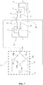
FIG. 7 shows a particular example of the current invention in a design with variable resistors to adjust the gain, and the inverting input of each of the operational amplifiers is connected to the non-inverting input of the other using impedances and also, it is connected to a Wheatstone bridge. -
FIG. 8 shows a particular example of the current invention in a design with variable impedances to adjust the gain, and the inverting input of each of the operational amplifiers is connected to the non-inverting input of the other, with the diodes inverted and to an inverter at the output of the circuit. -
FIG. 9 shows a particular example of the current invention in a design with variable resistances to adjust the gain, and the inverting input of each of the operational amplifiers is connected to the non-inverting input of the other via impedances, with the diodes reversed and an inverter at the exit of the circuit. -
FIG. 10 shows a particular example of the current invention in a design with variable impedances to adjust the gain, and the inverting input of each of the operational amplifiers is connected to the non-inverting input of the other, with the diodes reversed, and it is also connected to a Wheatstone bridge and an inverter at the circuit output. -
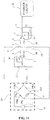
FIG. 11 shows a particular example of the current invention in a design with variable resistances to adjust the gain, and the inverting input of each of the operational amplifiers is connected to the non-inverting input of the other by means of impedances, with the diodes inverted, in addition it connects to a Wheatstone bridge and an inverter at the circuit output. -
FIG. 12 shows is a block diagram of a specific example of the current invention. - A sensor is a device, module, or subsystem which purpose is to detect events or changes in the environment such as light, a force, vibrations, temperature, sound, a magnetic field, or electric current and sends information to other electronic components, usually a computer or processor. The sensing action is, for example, taking electrical changes in impedance and sending information in the form of modulated signals to another electronic component.
- In
FIG. 2 , the current invention is a bidirectional sensor circuit consisting of: a sensing impedance (1) with a first terminal (1a) and a second terminal (1b); a first operational amplifier (2) which non-inverting input is connected to the first terminal (1a) and its inverting input is connected to the second terminal (1b); a second operational amplifier (3) with the non-inverting input connected to the second terminal (1b) and its inverting input is connected to the first terminal (1a); a first diode (4) with the anode connected to the inverting input of the first operational amplifier (2) and which cathode is connected to the output of the first operational amplifier (2); a second diode (5) with the anode connected to the output of the first operational amplifier (2) and to the cathode of the first diode (4); a variable impedance (13) connected to the anode of the first diode (4) and to the cathode of the second diode (5); a fourth diode (7) with the cathode connected to the cathode of the second diode (5) and to one end of the variable impedance (13); a third diode (6) with the anode connected to the inverting input of the second operational amplifier (3) and the cathode to the output of the second operational amplifier (3) and to the anode of the fourth diode (7); a variable impedance (12) connected to the cathode of the fourth diode (7) and to the anode of the third diode (6); where the input of the bidirectional sensor circuit consists of the terminals (1a) and (1b) the sensing impedance (1), and the output is at the anode of the second diode (5) and senses a load impedance connected to the first terminal (1a) of the sensing impedance (1). - The gain on the two operational amplifiers is adjusted so that the voltage output equals the same exact value of the current on the load impedance the sense impedance (1), and it is adjusted with the variable impedances (12) and (13) for a particular example of the invention they are variable impedances of any type.
- As a particular example of the same invention, the circuit of a mesh between the sensing impedance (1) and the load impedance (14) the value of the current corresponds to an integer multiple of the voltage value at the first terminal (1a) of the sensing impedance (1).
- In
FIG. 3 , in another particular example of the invention, the bidirectional sensor circuit is characterized by the non-inverting input of the first operational amplifier (2) that is connected to the first terminal (1a) through an impedance (9) and its inverting input is connected to the second terminal (1b) through an impedance (11); the non-inverting input of the second operational amplifier (3) is connected to the second terminal (1b) through an impedance (10) and its inverting input is connected to the first terminal (1a) through an impedance (8); where operational amplifiers are powered with a positive voltage V + and a negative voltage V-. - In a new particular example of the invention, referring to
FIG 4 , the bidirectional sensor circuit is connected to an alternating current source (15) in series with the load impedance (14), the other terminal of the load impedance (14) that is not connected to the alternating current source (15) connects to the first terminal (1a) of the sensing impedance (1), the free terminal of the alternating current source (15) connects to the second terminal (1b) of the sensing impedance (1), this allows laboratory tests to be carried out. - In
FIG. 5 , the non-inverting input of the first operational amplifier (2) is connected to the first terminal (1a) through an impedance (9) and its inverting input is connected to the second terminal (1b) through an impedance (11); the non-inverting input of the second operational amplifier (3) is connected to the second terminal (1b) through an impedance (10) and its inverting input is connected to the first terminal (1a) through an impedance (8); and a positive voltage V+ and a negative voltage V- power the operational amplifiers. This is another particular example of the invention where the bidirectional sensor circuit is characterized by an alternating current source (15) connected in series with a load impedance (14) also connected to the first terminal (1a) with the second terminal (1b) connected to the free terminal of the alternating current source (15), to carry out laboratory tests. -
FIG. 6 shows another particular example of the invention, where the terminals (1a) and (1b) of the sensing impedance (1) of the bidirectional sensor circuit are connected to an instrumentation Wheatstone bridge (19). - For the current invention, the instrumentation Wheatstone bridge (19) has: a first terminal (19a), a second terminal (19b), a third terminal (19c) and a fourth terminal (19d); a first impedance (19ac) connected to the first terminal (19a) and the third terminal (19c); a second impedance (19bc) connected to the second terminal (19b) and the third terminal (19c); a third impedance (19bd) connected to the second terminal (19b) and the fourth terminal (19d); an alternating current source (15) connected to the third terminal (19c) and the fourth terminal (19d); the first terminal (19a) connected to the second terminal (1b) of the sensing impedance (1); the second terminal (19b) connected to the first terminal (1a) of the sensing impedance (1); and a load impedance (14) is connected to the first terminal (19a) and the fourth terminal (19d).
- In
FIG. 7 , another particular example of the invention, for the bidirectional sensor circuit, the non-inverting input of the first operational amplifier (2) is connected to the first terminal (1a) through an impedance (9) and its inverting input is connected to the second terminal (1b) through an impedance (11); the non-inverting input of the second operational amplifier (3) is connected to the second terminal (1b) through an impedance (10) and its inverting input is connected to the first terminal (1a) through an impedance (8); and a positive voltage V+ and a negative voltage V- power the operational amplifiers. It also includes an instrumentation Wheatstone bridge (19) connected to terminals (1a) and (1b) of the sensing impedance (1). - For the current invention, the load impedance (14) corresponds to the impedance to be sensed in the circuit, in the case of a Wheatstone impedance bridge and for any particular example of the invention, this impedance is chosen from the group of variable impedances, photoresistors, thermoresistors, magnetic sensors, piezoelectric sensors, inductive sensors to measure a magnetic field, and electromagnetic transducers, among others, and combinations of the foregoing without being limited to this list.
- Referring to the example in
FIG. 5 , in detail, during a positive half-cycle of an alternating current input signal on the sensing impedance (1) the alternating current input signal enters through the non-inverting input of the first operational amplifier (2), while the first diode (4) is open, the variable impedance (13) serves as the gain impedance, and the first operational amplifier (2) works in non-inverting amplifier mode, in this case the gain is calculated as is known by the value of the variable impedance (13) on the value of the impedance (11), the voltage over the impedance (1) is expanded and measured at the output of the diode (5). On the other hand, during the same positive half-cycle of the signal on the sensing impedance (1), the positive current on the diode (6) keeps it closed and the second operational amplifier (3) is configured in voltage follower mode. However, at the second terminal (1b) connected to the non-inverting input of the second operational amplifier (3), there is a negative voltage, which keeps the diode (7) open, so that at the output of the second operational amplifier (3) any voltage is perceived. - Meanwhile, during the negative half-cycle, the first operational amplifier (2) is configured in voltage follower mode, no voltage is perceived at the output of the diode (5) when receiving negative voltage on the first terminal (1a) connected to its non-inverting input makes the diode (5) open. The second amplifier (3) instead, has the diode (6) open so that the impedance (12) works as an amplification impedance, and then the second operational amplifier (3) is configured as a non-inverting amplifier with a positive voltage over its non-inverting input. Thus, this configuration maintains a positive voltage output.
- The amplification gain on the operational amplifiers (2) and (3), is adjusted in such a way that the voltage output matches the same value of the current over the load impedance, preferably the value of the variable impedance (13) is variable just like the variable impedance value (12), and the impedance value of (11) and (8) is the same as well. The designer adjusts the gain of the circuit at will by varying the values of the variable impedances (13) and (12).
- This configuration makes it possible for the outputs of both amplifiers to be interconnected as only one is conducting and, therefore, no voltage accidents occur. Furthermore, the sensing impedance (1) is, for example, at least one order of magnitude compared to the input impedance, so that the voltage measured over it is comparable to the voltage over the signal impedance at to measure.
- In an alternative particular example of the invention, referring to
FIG. 8 , a reversed bidirectional sensor circuit, comprises: a sensing impedance (1) with a first terminal (1a) and a second terminal (1b); a first operational amplifier (2) for which the non-inverting input is connected to the first terminal (1a) and its inverting input is connected to the second terminal (1b); a second operational amplifier (3) with the non-inverting input connected to the second terminal (1b) and its inverting input is connected to the first terminal (1a); a first diode (4) with the cathode connected to the inverting input of the first operational amplifier (2) and for which the anode is connected to the output of the first operational amplifier (2); a second diode (5) with the cathode connected to the output of the first operational amplifier (2) and to the anode of the first diode (4); a variable impedance (13) connected to the cathode of the first diode (4) and to the anode of the second diode (5); a fourth diode (7) with the anode connected to the anode of the second diode (5) and to one end of the variable impedance (13); a third diode (6) with the cathode connected to the inverting input of the second operational amplifier (3) and the anode to the output of the second operational amplifier (3) and to the cathode of the fourth diode (7); a variable impedance (12) connected to the anode of the fourth diode (7) and to the cathode of the third diode (6); where the input of the bidirectional sensor circuit consists of the terminals (1a) and (1b) of the sensing impedance (1), and the output is at the anode of the second diode (5) connected to an operational inverter circuit (21), and senses a load impedance connected to the first terminal (1a) of the sensing impedance (1). - For the current invention, an operational inverter circuit is a circuit that inverts the input voltage and employs amplification, for example, an operational amplifier configured with unit negative gain or any gain as decided.
- In
FIG. 9 , as a particular example of the invention, for the reversing bidirectional sensor circuit the non-inverting input of the first operational amplifier (2) is connected to the first terminal (1a) through an impedance (9) and its inverting input connects to the second terminal (1b) through an impedance (11); the non-inverting input of the second operational amplifier (3) is connected to the second terminal (1b) through an impedance (10) and its inverting input is connected to the first terminal (1a) through an impedance (8); and a positive voltage V+ and a negative voltage V- power the operational amplifiers. - In
FIG. 10 , another example of the invention, the reversed bidirectional sensor circuit, shows an instrumentation Wheatstone bridge (19) connected to terminals (1a) and (1b) of the sensing impedance (1). - In
FIG. 10 , another particular example of the invention, the inverted bidirectional sensor circuit, where the non-inverting input of the first operational amplifier (2) is connected to the first terminal (1a) through an impedance (9) and its inverting input is connected to the second terminal (1b) through an impedance (11); the non-inverting input of the second operational amplifier (3) is connected to the second terminal (1b) through an impedance (10) and its inverting input is connected to the first terminal (1a) through an impedance (8); and a positive voltage V+ and a negative voltage V- power the operational amplifiers. It includes an instrumentation Wheatstone bridge (19) connected to terminals (1a) and (1b) of the sensing impedance (1). - In
FIG. 12 , as another example of the current invention, a circuit for sensing current changes on one or more transducers includes: a bidirectional sensor circuit (22); a digital analog converter (16) connected to the bidirectional sensor circuit (22); a control unit (17) connected to the digital analog converter (16); a signal generator (18) connected to the control unit (17); one or more transducers (20) connected to the output of the signal generator (18), and to the bidirectional sensor circuit (22); wherein the bidirectional sensor circuit (22) senses the current on the one or more transducers and sends a voltage that corresponds proportionally to the current on the one or more transducers (20). - It is possible to use the bidirectional sensor circuit to modulate a signal (for example, from a signal generator), in which the bidirectional sensor circuit is connected to sense the signal, and it is also connected to a digital-analog converter, and a control unit, allowing modulation and control of the signal generator.
- Instead, as another particular example of the current invention, for the bidirectional sensor circuit the anode of the second diode (5) is connected to the input of a digital-analog converter (16); and a control unit (17) is connected to the output of the digital-analog converter (16).
- In addition, the control unit (17) is connected to a signal generator (18) connected to a transducer (20), the transducer (20) is connected to the first terminal (1a) of the sensing impedance (1); wherein the transducer (20) is the load impedance (14).
- The control unit (17) commands the signal generator (18) using feedback of the output signal of the digital-analog converter (16).
- Likewise, as another example of the invention, the signal generator (18), is rather decoupled in impedance so as not to vary the load impedance (14).
- It should be understood that the current invention is not limited to the examples described and illustrated as for an expert, there are variations and possible modifications that do not depart from the spirit of the invention, which is only defined by the following claims.
Claims (7)
- A bi-directional sensor circuit comprising:- a sensing impedance (1) with a first terminal (1a) and a second terminal (1b);- a first operational amplifier (2) for which the non-inverting input is connected to the first terminal (1a) and its inverting input is connected to the second terminal (1b);- a second operational amplifier (3) with the non-inverting input connected to the second terminal (1b) and its inverting input is connected to the first terminal (1a);- a first diode (4) with the anode connected to the inverting input of the first operational amplifier (2) and for which the cathode is connected to the output of the first operational amplifier (2);- a second diode (5) with the anode connected to the output of the first operational amplifier (2) and to the cathode of the first diode (4);- a variable impedance (13) connected to the anode of the first diode (4) and to the cathode of the second diode (5);- a fourth diode (7) with the cathode connected to the cathode of the second diode (5) and to one end of the variable impedance (13);- a third diode (6) with the anode connected to the inverting input of the second operational amplifier (3) and the cathode to the output of the second operational amplifier (3) and to the anode of the fourth diode (7);- a variable impedance (12) connected to the cathode of the fourth diode (7) and the anode of the third diode (6);wherein the input of the bidirectional sensor circuit consists of the terminals (1a) and (1b) of the sensing impedance (1), and the output is at the anode of the second diode (5) and senses a load impedance connected to the first terminal (1a) of the sensing impedance (1).
- The circuit of Claim 1, wherein the non-inverting input of the first operational amplifier (2) is connected to the first terminal (1a) through an impedance (9) and its inverting input is connected to the second terminal (1b) through an impedance (11); the non-inverting input of the second operational amplifier (3) is connected to the second terminal (1b) through an impedance (10) and its inverting input is connected to the first terminal (1a) through an impedance (8).
- The circuit of Claim 1, wherein the anode-cathode terminals of all the diodes are reversed, an inverter circuit (14) is connected to the cathode of the diode, connected by its anode to the output of the first operational amplifier (2).
- The circuit of Claim 1, wherein the terminals (1a) and (1b) of the sensing impedance (1) are connected to an instrumentation Wheatstone bridge (19); the instrumentation Wheatstone bridge (19) has:- a first terminal (19a), a second terminal (19b), a third terminal (19c) and a fourth terminal (19d);- a second impedance (19ac) connected to the first terminal (19a) and to the third terminal (19c);- a third impedance (19bc) connected to the second terminal (19b) and the third terminal (19c);- a fourth impedance (19bd) connected to the second terminal (19b) and the fourth terminal (19d);- an alternating current generator (15) connected to the third terminal (19c) and the fourth terminal (19d)- the first terminal (19a) connected to the second terminal (1b) of the sensing impedance (1);- the second terminal (19b) connected to the first terminal (1a) of the sensing impedance (1); and- a load impedance (14) is connected to the first terminal (19a) and the fourth terminal (19d);
- The circuit of Claim 1, wherein the anode of the second diode (5) connects to the input of a digital-analog converter (16); and a control unit (17) is connected to the output of the digital-analog converter (16).
- The circuit of Claim 5, wherein the control unit (17) is connected to a signal generator (18) connected to a transducer (20), the transducer (20) is connected to the first terminal (1a) of the sensing impedance (1); wherein the transducer (20) is the load impedance (14).
- A bi-directional sensor circuit with inverter, comprising:- a sensing impedance (1) with a first terminal (1a) and a second terminal (1b);- a first operational amplifier (2) for which the non-inverting input is connected to the first terminal (1a) and its inverting input is connected to the second terminal (1b);- a second operational amplifier (3) with the non-inverting input connected to the second terminal (1b) and its inverting input is connected to the first terminal (1a);- a first diode (4) with the cathode connected to the inverting input of the first operational amplifier (2) and for which the anode is connected to the output of the first operational amplifier (2);- a second diode (5) with the cathode connected to the output of the first operational amplifier (2) and to the anode of the first diode (4);- a variable impedance (13) connected to the cathode of the first diode (4) and to the anode of the second diode (5); a fourth diode (7) with the anode connected to the anode of the second diode (5) and to one end of the variable impedance (13);- a third diode (6) with the cathode connected to the inverting input of the second operational amplifier (3) and the anode to the output of the second operational amplifier (3) and to the cathode of the fourth diode (7);- a variable impedance (12) connected to the anode of the fourth diode (7) and the cathode of the third diode (6);wherein the input of the bidirectional sensor circuit consists of the terminals (1a) and (1b) of the sensing impedance (1), and the output is at the anode of the second diode (5) connected to an operational inverter circuit (21), and senses a load impedance connected to the first terminal (1a) of the sensing impedance (1).
Applications Claiming Priority (2)
| Application Number | Priority Date | Filing Date | Title |
|---|---|---|---|
| CO2017013355 | 2017-12-22 | ||
| PCT/IB2018/060548 WO2019123431A1 (en) | 2017-12-22 | 2018-12-21 | Bidirectional sensor circuit |
Publications (4)
| Publication Number | Publication Date |
|---|---|
| EP3730047A1 true EP3730047A1 (en) | 2020-10-28 |
| EP3730047A4 EP3730047A4 (en) | 2021-09-22 |
| EP3730047B1 EP3730047B1 (en) | 2025-05-14 |
| EP3730047C0 EP3730047C0 (en) | 2025-05-14 |
Family
ID=66993215
Family Applications (1)
| Application Number | Title | Priority Date | Filing Date |
|---|---|---|---|
| EP18890563.2A Active EP3730047B1 (en) | 2017-12-22 | 2018-12-21 | Bidirectional sensor circuit |
Country Status (6)
| Country | Link |
|---|---|
| US (1) | US11448667B2 (en) |
| EP (1) | EP3730047B1 (en) |
| JP (1) | JP7345472B2 (en) |
| CN (1) | CN111787857B (en) |
| ES (1) | ES3037968T3 (en) |
| WO (1) | WO2019123431A1 (en) |
Family Cites Families (11)
| Publication number | Priority date | Publication date | Assignee | Title |
|---|---|---|---|---|
| JP2593253B2 (en) * | 1991-05-29 | 1997-03-26 | 富士通株式会社 | Current measurement circuit |
| US5498984A (en) * | 1994-09-30 | 1996-03-12 | Maxim Integrated Products | High side, current sense amplifier using a symmetric amplifier |
| US5838145A (en) * | 1996-05-30 | 1998-11-17 | Poon; Franki Ngai Kit | Transient load corrector for switching converters |
| US6198296B1 (en) * | 1999-01-14 | 2001-03-06 | Burr-Brown Corporation | Bridge sensor linearization circuit and method |
| US6985774B2 (en) | 2000-09-27 | 2006-01-10 | Cvrx, Inc. | Stimulus regimens for cardiovascular reflex control |
| DE602004001216T2 (en) * | 2003-02-12 | 2007-05-03 | Koninklijke Philips Electronics N.V. | POWER MONITORING SYSTEM WITH A BIDIRECTIONAL CURRENT SENSOR |
| EP2493551A4 (en) | 2009-10-26 | 2013-04-17 | Emkinetics Inc | Method and apparatus for electromagnetic stimulation of nerve, muscle, and body tissues |
| US8687386B2 (en) * | 2010-12-06 | 2014-04-01 | The Boeing Company | Synchronous rectifier bi-directional current sensor |
| US9361975B2 (en) * | 2013-03-11 | 2016-06-07 | Adesto Technologies Corporation | Sensing data in resistive switching memory devices |
| US10295371B2 (en) * | 2014-08-08 | 2019-05-21 | Johnson Electric International AG | Electronic device and magnetic sensor integrated circuit |
| CA3007678A1 (en) * | 2018-06-08 | 2019-12-08 | Hud Studios Inc. | Bi-directional force sensor |
-
2018
- 2018-12-21 US US16/955,829 patent/US11448667B2/en active Active
- 2018-12-21 ES ES18890563T patent/ES3037968T3/en active Active
- 2018-12-21 EP EP18890563.2A patent/EP3730047B1/en active Active
- 2018-12-21 JP JP2020533189A patent/JP7345472B2/en active Active
- 2018-12-21 CN CN201880088183.3A patent/CN111787857B/en active Active
- 2018-12-21 WO PCT/IB2018/060548 patent/WO2019123431A1/en not_active Ceased
Also Published As
| Publication number | Publication date |
|---|---|
| ES3037968T3 (en) | 2025-10-08 |
| WO2019123431A1 (en) | 2019-06-27 |
| JP2021508818A (en) | 2021-03-11 |
| US11448667B2 (en) | 2022-09-20 |
| EP3730047B1 (en) | 2025-05-14 |
| JP7345472B2 (en) | 2023-09-15 |
| US20210072290A1 (en) | 2021-03-11 |
| EP3730047A4 (en) | 2021-09-22 |
| CN111787857B (en) | 2024-10-01 |
| CN111787857A (en) | 2020-10-16 |
| EP3730047C0 (en) | 2025-05-14 |
Similar Documents
| Publication | Publication Date | Title |
|---|---|---|
| US9521493B2 (en) | Transducer impedance measurement for hearing aid | |
| CA2159854C (en) | Self-powered interface circuit for use with a transducer sensor | |
| US9585593B2 (en) | Signal distribution for patient-electrode measurements | |
| KR20160009982A (en) | Method and apparatus for measuring bio impedance | |
| CN104096314B (en) | Based on the self-adapting multi-channel transcutaneous electrostimulation device of vector impedance feedback | |
| JP2018094412A (en) | Wearable biological sensor and noise cancel circuit | |
| JP5687311B2 (en) | Voltage measurement circuit | |
| KR102438775B1 (en) | Impedance measuring device and method | |
| EP3730047B1 (en) | Bidirectional sensor circuit | |
| JPWO2018150849A1 (en) | Biological information measuring device, control method of biological information measuring device, and control program of biological information measuring device | |
| US20210333233A1 (en) | Semiconductor device, biological signal sensor and biological signal sensor system | |
| US6680642B2 (en) | Analog bipolar current source | |
| JPS61501799A (en) | Voltage-current converter | |
| RU2631494C1 (en) | Universal module of frequency integration developing transducer for sensors of physical value sensors | |
| US20240402812A1 (en) | Vibrotactile Actuator Sensing And Control Using Current Measurement | |
| KR101504116B1 (en) | EEG signal detecting device | |
| CN114984453A (en) | An impedance detection device for multi-channel transcranial electrical stimulator | |
| US9936893B2 (en) | Device for detecting electric potentials | |
| JP4859353B2 (en) | Amplification circuit and test apparatus | |
| EP4382161A1 (en) | A stimulator circuit, a system for providing stimulation of a brain and/or nerve and a method for providing a compensated stimulation signal | |
| JP6575642B1 (en) | Muscle evaluation system | |
| CN109464745B (en) | Novel pulse treatment device based on biological negative feedback | |
| JP2026045718A (en) | Sensor device | |
| KR20250138796A (en) | Circuit, method, and electronic device for measuring bioimpedance | |
| JPH1189803A (en) | Telemetering device for implantable devices |
Legal Events
| Date | Code | Title | Description |
|---|---|---|---|
| STAA | Information on the status of an ep patent application or granted ep patent |
Free format text: STATUS: THE INTERNATIONAL PUBLICATION HAS BEEN MADE |
|
| PUAI | Public reference made under article 153(3) epc to a published international application that has entered the european phase |
Free format text: ORIGINAL CODE: 0009012 |
|
| STAA | Information on the status of an ep patent application or granted ep patent |
Free format text: STATUS: REQUEST FOR EXAMINATION WAS MADE |
|
| 17P | Request for examination filed |
Effective date: 20200716 |
|
| AK | Designated contracting states |
Kind code of ref document: A1 Designated state(s): AL AT BE BG CH CY CZ DE DK EE ES FI FR GB GR HR HU IE IS IT LI LT LU LV MC MK MT NL NO PL PT RO RS SE SI SK SM TR |
|
| AX | Request for extension of the european patent |
Extension state: BA ME |
|
| DAV | Request for validation of the european patent (deleted) | ||
| DAX | Request for extension of the european patent (deleted) | ||
| REG | Reference to a national code |
Ref country code: DE Free format text: PREVIOUS MAIN CLASS: A61B0005040000 Ipc: A61B0005300000 Ref country code: DE Ref legal event code: R079 Ref document number: 602018082011 Country of ref document: DE Free format text: PREVIOUS MAIN CLASS: A61B0005040000 Ipc: A61B0005300000 |
|
| A4 | Supplementary search report drawn up and despatched |
Effective date: 20210825 |
|
| RIC1 | Information provided on ipc code assigned before grant |
Ipc: G01R 31/14 20060101ALI20210819BHEP Ipc: A61B 5/30 20210101AFI20210819BHEP |
|
| REG | Reference to a national code |
Ref country code: DE Ref legal event code: R079 Free format text: PREVIOUS MAIN CLASS: A61B0005300000 Ipc: A61B0005000000 Ref country code: DE Ref legal event code: R079 Ref document number: 602018082011 Country of ref document: DE Free format text: PREVIOUS MAIN CLASS: A61B0005300000 Ipc: A61B0005000000 |
|
| GRAP | Despatch of communication of intention to grant a patent |
Free format text: ORIGINAL CODE: EPIDOSNIGR1 |
|
| STAA | Information on the status of an ep patent application or granted ep patent |
Free format text: STATUS: GRANT OF PATENT IS INTENDED |
|
| RIC1 | Information provided on ipc code assigned before grant |
Ipc: G01R 31/14 20060101ALI20241128BHEP Ipc: G01R 19/00 20060101ALI20241128BHEP Ipc: G01R 1/30 20060101ALI20241128BHEP Ipc: A61B 5/30 20210101ALI20241128BHEP Ipc: A61B 5/00 20060101AFI20241128BHEP |
|
| INTG | Intention to grant announced |
Effective date: 20241206 |
|
| GRAS | Grant fee paid |
Free format text: ORIGINAL CODE: EPIDOSNIGR3 |
|
| GRAA | (expected) grant |
Free format text: ORIGINAL CODE: 0009210 |
|
| STAA | Information on the status of an ep patent application or granted ep patent |
Free format text: STATUS: THE PATENT HAS BEEN GRANTED |
|
| AK | Designated contracting states |
Kind code of ref document: B1 Designated state(s): AL AT BE BG CH CY CZ DE DK EE ES FI FR GB GR HR HU IE IS IT LI LT LU LV MC MK MT NL NO PL PT RO RS SE SI SK SM TR |
|
| REG | Reference to a national code |
Ref country code: GB Ref legal event code: FG4D |
|
| REG | Reference to a national code |
Ref country code: CH Ref legal event code: EP |
|
| REG | Reference to a national code |
Ref country code: IE Ref legal event code: FG4D |
|
| REG | Reference to a national code |
Ref country code: DE Ref legal event code: R096 Ref document number: 602018082011 Country of ref document: DE |
|
| U01 | Request for unitary effect filed |
Effective date: 20250612 |
|
| U07 | Unitary effect registered |
Designated state(s): AT BE BG DE DK EE FI FR IT LT LU LV MT NL PT RO SE SI Effective date: 20250623 |
|
| REG | Reference to a national code |
Ref country code: ES Ref legal event code: FG2A Ref document number: 3037968 Country of ref document: ES Kind code of ref document: T3 Effective date: 20251008 |
|
| PG25 | Lapsed in a contracting state [announced via postgrant information from national office to epo] |
Ref country code: NO Free format text: LAPSE BECAUSE OF FAILURE TO SUBMIT A TRANSLATION OF THE DESCRIPTION OR TO PAY THE FEE WITHIN THE PRESCRIBED TIME-LIMIT Effective date: 20250814 Ref country code: GR Free format text: LAPSE BECAUSE OF FAILURE TO SUBMIT A TRANSLATION OF THE DESCRIPTION OR TO PAY THE FEE WITHIN THE PRESCRIBED TIME-LIMIT Effective date: 20250815 |
|
| PG25 | Lapsed in a contracting state [announced via postgrant information from national office to epo] |
Ref country code: PL Free format text: LAPSE BECAUSE OF FAILURE TO SUBMIT A TRANSLATION OF THE DESCRIPTION OR TO PAY THE FEE WITHIN THE PRESCRIBED TIME-LIMIT Effective date: 20250514 |
|
| PG25 | Lapsed in a contracting state [announced via postgrant information from national office to epo] |
Ref country code: HR Free format text: LAPSE BECAUSE OF FAILURE TO SUBMIT A TRANSLATION OF THE DESCRIPTION OR TO PAY THE FEE WITHIN THE PRESCRIBED TIME-LIMIT Effective date: 20250514 |
|
| PG25 | Lapsed in a contracting state [announced via postgrant information from national office to epo] |
Ref country code: RS Free format text: LAPSE BECAUSE OF FAILURE TO SUBMIT A TRANSLATION OF THE DESCRIPTION OR TO PAY THE FEE WITHIN THE PRESCRIBED TIME-LIMIT Effective date: 20250814 |
|
| PG25 | Lapsed in a contracting state [announced via postgrant information from national office to epo] |
Ref country code: IS Free format text: LAPSE BECAUSE OF FAILURE TO SUBMIT A TRANSLATION OF THE DESCRIPTION OR TO PAY THE FEE WITHIN THE PRESCRIBED TIME-LIMIT Effective date: 20250914 |
|
| U20 | Renewal fee for the european patent with unitary effect paid |
Year of fee payment: 8 Effective date: 20251105 |
|
| PGFP | Annual fee paid to national office [announced via postgrant information from national office to epo] |
Ref country code: GB Payment date: 20251105 Year of fee payment: 8 |
|
| PG25 | Lapsed in a contracting state [announced via postgrant information from national office to epo] |
Ref country code: SM Free format text: LAPSE BECAUSE OF FAILURE TO SUBMIT A TRANSLATION OF THE DESCRIPTION OR TO PAY THE FEE WITHIN THE PRESCRIBED TIME-LIMIT Effective date: 20250514 |
|
| PG25 | Lapsed in a contracting state [announced via postgrant information from national office to epo] |
Ref country code: CZ Free format text: LAPSE BECAUSE OF FAILURE TO SUBMIT A TRANSLATION OF THE DESCRIPTION OR TO PAY THE FEE WITHIN THE PRESCRIBED TIME-LIMIT Effective date: 20250514 |
|
| PG25 | Lapsed in a contracting state [announced via postgrant information from national office to epo] |
Ref country code: SK Free format text: LAPSE BECAUSE OF FAILURE TO SUBMIT A TRANSLATION OF THE DESCRIPTION OR TO PAY THE FEE WITHIN THE PRESCRIBED TIME-LIMIT Effective date: 20250514 |
|
| PLBE | No opposition filed within time limit |
Free format text: ORIGINAL CODE: 0009261 |
|
| STAA | Information on the status of an ep patent application or granted ep patent |
Free format text: STATUS: NO OPPOSITION FILED WITHIN TIME LIMIT |
|
| REG | Reference to a national code |
Ref country code: CH Ref legal event code: L10 Free format text: ST27 STATUS EVENT CODE: U-0-0-L10-L00 (AS PROVIDED BY THE NATIONAL OFFICE) Effective date: 20260325 |
|
| PGFP | Annual fee paid to national office [announced via postgrant information from national office to epo] |
Ref country code: ES Payment date: 20260122 Year of fee payment: 8 |
|
| 26N | No opposition filed |
Effective date: 20260217 |