EP3729796B1 - Bildgebungsverfahrens und bildgebungsvorrichtung geeignet für stark und scwach licht - Google Patents
Bildgebungsverfahrens und bildgebungsvorrichtung geeignet für stark und scwach licht Download PDFInfo
- Publication number
- EP3729796B1 EP3729796B1 EP18815765.5A EP18815765A EP3729796B1 EP 3729796 B1 EP3729796 B1 EP 3729796B1 EP 18815765 A EP18815765 A EP 18815765A EP 3729796 B1 EP3729796 B1 EP 3729796B1
- Authority
- EP
- European Patent Office
- Prior art keywords
- imaging mode
- imaging
- photon
- mode
- counting
- Prior art date
- Legal status (The legal status is an assumption and is not a legal conclusion. Google has not performed a legal analysis and makes no representation as to the accuracy of the status listed.)
- Active
Links
- 238000003384 imaging method Methods 0.000 title claims description 183
- 238000000034 method Methods 0.000 title claims description 20
- 230000008569 process Effects 0.000 title description 7
- 230000004907 flux Effects 0.000 claims description 40
- 238000005286 illumination Methods 0.000 claims description 38
- 230000003595 spectral effect Effects 0.000 claims description 14
- 230000010354 integration Effects 0.000 claims description 12
- 230000002349 favourable effect Effects 0.000 claims description 9
- 230000003287 optical effect Effects 0.000 claims description 8
- 230000005540 biological transmission Effects 0.000 claims description 5
- 230000001360 synchronised effect Effects 0.000 claims description 3
- 230000003321 amplification Effects 0.000 description 14
- 238000003199 nucleic acid amplification method Methods 0.000 description 14
- 239000011159 matrix material Substances 0.000 description 12
- 238000001514 detection method Methods 0.000 description 9
- 238000005516 engineering process Methods 0.000 description 6
- 230000007423 decrease Effects 0.000 description 5
- 238000009826 distribution Methods 0.000 description 4
- 230000006870 function Effects 0.000 description 4
- 238000001444 catalytic combustion detection Methods 0.000 description 3
- 230000009467 reduction Effects 0.000 description 3
- 230000008901 benefit Effects 0.000 description 2
- 230000015572 biosynthetic process Effects 0.000 description 2
- 238000004422 calculation algorithm Methods 0.000 description 2
- 230000015556 catabolic process Effects 0.000 description 2
- 238000006731 degradation reaction Methods 0.000 description 2
- 238000002059 diagnostic imaging Methods 0.000 description 2
- 210000001747 pupil Anatomy 0.000 description 2
- 230000035945 sensitivity Effects 0.000 description 2
- PEDCQBHIVMGVHV-UHFFFAOYSA-N Glycerine Chemical compound OCC(O)CO PEDCQBHIVMGVHV-UHFFFAOYSA-N 0.000 description 1
- 241000282414 Homo sapiens Species 0.000 description 1
- 241000135309 Processus Species 0.000 description 1
- 238000010521 absorption reaction Methods 0.000 description 1
- 238000009825 accumulation Methods 0.000 description 1
- 238000004364 calculation method Methods 0.000 description 1
- 230000008859 change Effects 0.000 description 1
- 230000003247 decreasing effect Effects 0.000 description 1
- 239000006185 dispersion Substances 0.000 description 1
- 229940082150 encore Drugs 0.000 description 1
- 230000006872 improvement Effects 0.000 description 1
- 230000000422 nocturnal effect Effects 0.000 description 1
- 238000005457 optimization Methods 0.000 description 1
- 230000035807 sensation Effects 0.000 description 1
- 238000001228 spectrum Methods 0.000 description 1
- 238000005309 stochastic process Methods 0.000 description 1
- 230000002123 temporal effect Effects 0.000 description 1
Images


Classifications
-
- G—PHYSICS
- G01—MEASURING; TESTING
- G01J—MEASUREMENT OF INTENSITY, VELOCITY, SPECTRAL CONTENT, POLARISATION, PHASE OR PULSE CHARACTERISTICS OF INFRARED, VISIBLE OR ULTRAVIOLET LIGHT; COLORIMETRY; RADIATION PYROMETRY
- G01J1/00—Photometry, e.g. photographic exposure meter
- G01J1/42—Photometry, e.g. photographic exposure meter using electric radiation detectors
- G01J1/4228—Photometry, e.g. photographic exposure meter using electric radiation detectors arrangements with two or more detectors, e.g. for sensitivity compensation
-
- G—PHYSICS
- G01—MEASURING; TESTING
- G01J—MEASUREMENT OF INTENSITY, VELOCITY, SPECTRAL CONTENT, POLARISATION, PHASE OR PULSE CHARACTERISTICS OF INFRARED, VISIBLE OR ULTRAVIOLET LIGHT; COLORIMETRY; RADIATION PYROMETRY
- G01J1/00—Photometry, e.g. photographic exposure meter
- G01J1/02—Details
- G01J1/0228—Control of working procedures; Failure detection; Spectral bandwidth calculation
-
- H—ELECTRICITY
- H04—ELECTRIC COMMUNICATION TECHNIQUE
- H04N—PICTORIAL COMMUNICATION, e.g. TELEVISION
- H04N25/00—Circuitry of solid-state image sensors [SSIS]; Control thereof
- H04N25/40—Extracting pixel data from image sensors by controlling scanning circuits, e.g. by modifying the number of pixels sampled or to be sampled
- H04N25/42—Extracting pixel data from image sensors by controlling scanning circuits, e.g. by modifying the number of pixels sampled or to be sampled by switching between different modes of operation using different resolutions or aspect ratios, e.g. switching between interlaced and non-interlaced mode
-
- H—ELECTRICITY
- H04—ELECTRIC COMMUNICATION TECHNIQUE
- H04N—PICTORIAL COMMUNICATION, e.g. TELEVISION
- H04N25/00—Circuitry of solid-state image sensors [SSIS]; Control thereof
- H04N25/50—Control of the SSIS exposure
-
- G—PHYSICS
- G01—MEASURING; TESTING
- G01J—MEASUREMENT OF INTENSITY, VELOCITY, SPECTRAL CONTENT, POLARISATION, PHASE OR PULSE CHARACTERISTICS OF INFRARED, VISIBLE OR ULTRAVIOLET LIGHT; COLORIMETRY; RADIATION PYROMETRY
- G01J1/00—Photometry, e.g. photographic exposure meter
- G01J1/42—Photometry, e.g. photographic exposure meter using electric radiation detectors
- G01J1/44—Electric circuits
- G01J2001/4413—Type
- G01J2001/442—Single-photon detection or photon counting
-
- H—ELECTRICITY
- H04—ELECTRIC COMMUNICATION TECHNIQUE
- H04N—PICTORIAL COMMUNICATION, e.g. TELEVISION
- H04N5/00—Details of television systems
- H04N5/30—Transforming light or analogous information into electric information
- H04N5/33—Transforming infrared radiation
Definitions
- the field of the invention is that of imaging and more particularly low light level imaging.
- the signal-to-noise ratio decreases until it becomes insufficient for vision.
- the signal is then drowned in the noise generated by the detector and the image coming from the detector is unusable or very degraded.
- the sensitivity and noise of the detector limit the performance for imaging at very low light levels.
- Low Light Level imagers are optimized by increasing the pixel area and increasing the integration time as much as possible.
- the analog signal at the output of the detector is fluctuating and is dominated by read noise and dark noise for a pixel which has not generated any photoelectrons, and multiplication noise for pixels which have converted 1 or more photoelectrons.
- the a priori knowledge of the number of photons received, less than 0.15 on average constrains us at the output to two states: either we have received 0 photon or we have received 1, in 99% of cases.
- the binarization of the frame by this method however leads to residual noise linked to the photon counting rate error.
- This residual noise can be characterized by a probability of counting error which can always be estimated and bounded by using noise statistics and Poisson's law. This probability breaks down into the probability of counting 1 for 0 incident photon, the probability of counting 0 for 1 incident photon and again the probability of counting 1 for 2 or more incident photons.
- the last step of photon-counting imaging consists of summing several elementary binary frames to reconstitute an image corresponding to the output image restitution rate, for example for a video output rate of 25 Hz, i.e. 40 ms accumulation time of the elementary frames obtained at the highest rate.
- the sum of the different binarized frames makes it possible to reconstitute an image with different levels of gray. Number of discernible shades of gray is no longer dominated by the dispersion of the multiplication gains of the signal amplification process which is at the origin of the sensation of snow dominating the image and its shades.
- this amplification noise factor is different for different types of detectors.
- SPAD technologies Single Photon Avalanche Diode
- avalanche photodiode in Geiger mode the absorption of a photon causes a giant avalanche process.
- the current generated by the avalanche is detected by an electronic circuit which allows the detection of the photon.
- a dead time is necessary to evacuate the charges and therefore prevents the detection of a new photon during this evacuation time. It is not this type of technology that is preferred and presented here.
- the imaging system can be forced to switch to a mode specific to "forced" photon-counting imaging, by placing oneself in conditions making it possible to be in this regime constrained to 0 or 1 photon per pixel for a frame.
- the parameters of the acquisition device are typically parameters of cadence time and/or integration time and/or optical aperture and/or spectral band variation and/or optical attenuation variation .
- the acquisition parameters according to the classic imaging mode and the parameters according to the natural photon counting imaging mode typically have fixed values, and the parameters according to the forced photon counting imaging mode typically have values varying from one iteration to another to optimize the image quality criterion at each iteration.
- the method includes a step of spatial division of each frame into subframes and the steps of the imaging modes are applied to each subframe.
- the estimation of the quality of the image obtained can be determined by calculation or by an operator.
- such a method can advantageously be used in active imaging, that is to say with laser illumination.
- the parameters of the acquisition device can advantageously lead to reducing the laser illumination of the scene or even to increasing its range.
- the method includes a prior step of illuminating the scene by means of an illumination device synchronized with the acquisition device and the illumination device and the acquisition device have the same spectral band.
- illumination parameters can also be defined in step A.
- the illumination parameters are for example power and/or illumination duration parameters of the illumination device.
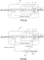
- the invention also relates to a system for imaging a scene which comprises a device for acquiring frames of the scene, possibly a device for illuminating the scene, and a processing unit connected to the acquisition device and to the optional illumination device, configured to implement the imaging method as described.
- the imaging system instead of undergoing the scene flow received, the imaging system according to the invention adapts its operating parameters, such as for example its acquisition rate, to be in the imaging mode presenting the best performance.
- the imaging system is forced to switch to a specific mode of imaging with forced photon counting, by placing the imaging system in conditions allowing it to be in this regime constrained to 0 or 1 photon per pixel for a frame: the imaging system is constrained by adjusting one or more of its various parameters (integration time, rate, aperture, illumination for active imaging, etc.) to be able to be in the particular mode where advantageously, from the point of view of the restored image quality, photon counting can be done.
- the imaging system instead of undergoing the scene flow received, the imaging system according to the invention adapts its operating parameters, such as for example its acquisition rate, to be in the imaging mode presenting the best performance.
- Switching between the different imaging modes is done according to the scene flow received or more precisely according to the quality of the image obtained according to one or the other imaging mode, this quality being linked to the flow scene received. It can be done automatically by being provided by the processing unit 2 or manually. It can be done on the whole of the detection matrix 11 ( ⁇ on each acquired frame) or only on a part ( ⁇ sub-frame or window), even if the matrix allows it, per pixel, which makes it possible to fine-tuning the imaging mode to the stream received.
- the imaging system adapts its parameters to remain in a photon counting imaging mode.
- the parameters of the acquisition device are controlled by favoring the increase in the frame rate and thus the reduction of the integration time, the limitation or even the reduction of the spectral band.
- the method according to the invention also makes it possible to use a matrix of detectors whose pixel size is reduced, even if it means using binning modes (as in CCDs) which make it possible to sum the charges on adjacent pixels (2x2, 3x3 or 4x4) for example to effectively increase the pixel size.
- the parameters of the conventional imaging mode and those of the natural counting imaging mode are predetermined and have predetermined values.
- Those of the parameters of the natural counting imaging mode correspond to the ultimate conditions of use of the acquisition device, corresponding for example to 0.15 photon/pixel or less for each frame.
- the parameters of the forced counting imaging mode are variable: the parameters can vary from one image to another and their values are optimized from one image to another to optimize the image quality criterion from one image to another. the other. They are generally optimized by the processing unit within a range of values, proceeding in steps from one iteration to another. These ranges of values are between the values of the parameters in classic mode and those of the parameters in natural counting mode.
- the processing unit determines whether the current imaging mode (chosen in step A) is the conventional mode. If the current imaging mode (chosen in step A) is the conventional mode, an image is obtained from these frames by the processing unit in a conventional manner (acquisition of at least one frame and summation of the frames to get the final image).
- the image obtained according to one mode or the other is sent for example to a display device.
- the quality of the image obtained is compared (2nd comparison) with a second predetermined image quality (quality2), corresponding to an image quality in mode with natural metering, by means of the processing unit.
- new frames can be acquired according to two imaging modes (classic and forced counting, or forced counting and natural counting) and between the two, the imaging mode which gives the best quality criterion is chosen. This amounts to defining these quality criteria in a relative manner.
- a level of incident illumination on the scene or even at the pupil entrance or even in the focal plane has been given; it is of course possible to take other criteria known to those skilled in the art such as the signal to noise ratio (temporal or spatial), the dynamic range in restored gray levels.
- the initial imaging mode can be either mode. This initial mode is engaged without knowing the level of illumination of the scene flow received. In the example of the picture 3 , the classic mode was chosen as the initial mode symbolized by a dotted arrow. But if one chooses an imaging mode by photon counting (natural or forced), the comparison tests to qualities 1 and 2 are of course reversed to keep the acquisition parameters as long as it is not necessary to change them.
- the method comprises the following steps.
- the parameters of the conventional imaging mode and those of the natural counting imaging mode are predetermined and have predetermined values.
- Those of the parameters of the natural counting imaging mode correspond to the ultimate conditions of use of the acquisition device, corresponding for example to 0.15 photon/pixel or less for each frame.
- the parameters of the forced counting imaging mode are variable: the parameters can vary from one image to another and their values are optimized from one image to another to optimize the image quality criterion from one image to another. the other. They are generally optimized by the processing unit within a range of values, proceeding step by step from one iteration to the next. These ranges of values are between the values of the parameters in classic mode and those of the parameters in natural counting mode.
- the processing unit determines whether the current imaging mode (chosen in step A) is the conventional mode. If the current imaging mode (chosen in step A) is the conventional mode, an image is obtained from these frames by the processing unit in a conventional manner (acquisition of at least one frame and summation of the frames to get the final image).
- the image obtained according to one mode or the other is sent for example to a display device.
- the acquired frames are spatially divided into sub-frames or windows, this spatial division being able to go so far as to consider in each frame a fraction of the pixels (window, rows, columns or still pixel determined).
- the steps of the different imaging modes are then applied to each subframe.
- This imaging method is in particular well suited to active imaging which then includes a prior stage of illumination of the scene by an illumination device (laser, LED, lamp) 200 shown figure 2b generally synchronized with the acquisition device 1.
- the spectral band of the acquisition device will then be restricted to that of the illumination device and thus only the photons of the scene reflected in this band will be counted. It is also possible to reduce the power or the durations of illumination of the illumination device.
- the spectral band, the power or the durations of illumination are then illumination parameters also controlled by the processing unit 2.
Landscapes
- Engineering & Computer Science (AREA)
- Multimedia (AREA)
- Signal Processing (AREA)
- Physics & Mathematics (AREA)
- Spectroscopy & Molecular Physics (AREA)
- General Physics & Mathematics (AREA)
- Studio Devices (AREA)
- Transforming Light Signals Into Electric Signals (AREA)
- Liquid Crystal Display Device Control (AREA)
- Solid State Image Pick-Up Elements (AREA)
Claims (11)
- Verfahren zum Abbilden einer Szene mittels eines Bildgebungssystems (100), mit dem ein Bild der Szene erhalten werden kann, wobei das Bildgebungssystem ein Gerät (1) zur Erfassung von Frames gemäß Erfassungsparametern umfasst, wobei das Gerät einen Detektor, der Pixel umfasst, und eine Einheit (2) zur Verarbeitung der erfassten Frames umfasst, dadurch gekennzeichnet, dass das Verfahren die folgenden Schritte umfasst:A) Auswählen eines Bildgebungsmodus aus einem herkömmlichen Bildgebungsmodus, einem Bildgebungsmodus mit natürlicher Photonenzählung und einem Bildgebungsmodus mit erzwungener Photonenzählung,wobei der klassische Bildgebungsmodus geeignet ist, wenn der Photonenfluss pro Pixel und Frame groß ist, und bei dem mindestens ein Frame erfasst wird und dann die Frames summiert werden, um ein Bild zu erhalten,wobei der Bildgebungsmodus mit natürlicher Photonenzählung geeignet ist, wenn der Photonenfluss pro Pixel und Frame sehr niedrig ist,wobei der Bildgebungsmodus mit erzwungener Photonenzählung einem Photonenfluss pro Pixel und pro Frame entspricht, der zwischen demjenigen, der dem herkömmlichen Bildgebungsmodus entspricht, und demjenigen, der dem Bildgebungsmodus mit natürlicher Photonenzählung entspricht, liegtund wobei der Photonenfluss pro Pixel und pro Frame so reduziert wird, dass ein Niveau erreicht wird, das dem Bildgebungsmodus mit natürlicher Photonenzählung entspricht,und, in Abhängigkeit vom gewählten Bildgebungsmodus,Bestimmen der entsprechenden Erfassungsparameter durch die Verarbeitungseinheit,B) Erfassen mindestens eines Frames durch das Erfassungsgerät, das mit den Erfassungsparametern parametrisiert ist, und Übertragen der erfassten Frames zur Verarbeitungseinheit, um ein Bild zu erhalten, wobei das Bild nach den folgenden Teilschritten erhalten wird, wenn der gewählte Bildgebungsmodus der Bildgebungsmodus mit natürlicher Photonenzählung oder der Bildgebungsmodus mit erzwungener Photonenzählung ist:- Binarisieren der erfassten Frames und- Summieren der binarisierten Frames, um ein Bild zu erhalten,C) Schätzen der Qualität des erhaltenen Bildes,D) D1) Bestimmen, in Abhängigkeit von der Qualität des erhaltenen Bildes, eines oder zweier neuer Bildgebungsmodi, ausgewählt aus dem herkömmlichen Bildgebungsmodus, dem Bildgebungsmodus mit natürlicher Photonenzählung oder dem Bildgebungsmodus mit erzwungener Photonenzählung,
D2) Wiederholen der Schritte A, B, C und D mit dem neuen als Bildgebungsmodus ausgewählten Bildgebungsmodus. - Verfahren zum Abbilden einer Szene nach dem vorhergehenden Anspruch, dadurch gekennzeichnet, dass der neue gewählte Bildgebungsmodus aus Schritt D1) durch Vergleichen (1. Vergleich) der Qualität des erhaltenen Bildes mit einer ersten vorbestimmten Qualität (Qualität1) entsprechend dem herkömmlichen Abbildungsmodus erhalten wird:- wenn der Vergleich (1. Vergleich) günstig ausfällt, ist der neue gewählte Bildgebungsmodus der herkömmliche Bildgebungsmodus,- andernfalls Vergleichen (2. Vergleich) der erhaltenen Bildqualität mit einer zweiten vorbestimmten Qualität (Qualität2) entsprechend dem Bildgebungsmodus mit natürlicher Photonenzählung, undo wenn der Vergleich (2. Vergleich) günstig ausfällt, ist der neue gewählte Bildgebungsmodus der Bildgebungsmodus mit natürlicher Photonenzählung,o andernfalls ist der neue gewählte Bildgebungsmodus der Bildgebungsmodus mit erzwungener Photonenzählung.
- Bildgebungsverfahren nach einem der vorhergehenden Ansprüche, dadurch gekennzeichnet, dass die Erfassungsparameter Erfassungsraten- und/oder Integrationszeit- und/oder Blenden- und/oder Spektralbandvariations- und/oder optische Dämpfungsvariationsparameter sind.
- Bildgebungsverfahren nach einem der vorhergehenden Ansprüche, dadurch gekennzeichnet, dass die Erfassungsparameter gemäß dem herkömmlichen Bildgebungsmodus und die Parameter gemäß dem Bildgebungsmodus mit natürlicher Photonenzählung feste Werte haben, und dadurch, dass die Erfassungsparameter gemäß dem Bildgebungsmodus mit erzwungener Photonenzählung Werte haben, die von Iteration zu Iteration variieren.
- Bildgebungsverfahren nach einem der vorhergehenden Ansprüche, dadurch gekennzeichnet, dass es einen Schritt des räumlichen Unterteilens jedes Frames in Subframes umfasst, und dadurch, dass die Schritte der Bildgebungsmodi auf jeden Subframe angewendet werden.
- Bildgebungsverfahren nach einem der vorhergehenden Ansprüche, dadurch gekennzeichnet, dass die Schätzung der Qualität des erhaltenen Bildes durch Berechnung oder durch einen Operator bestimmt wird.
- Bildgebungsverfahren nach einem der vorhergehenden Ansprüche, dadurch gekennzeichnet, dass es einen Vorabschritt des Beleuchtens der Szene mit Hilfe eines Beleuchtungsgeräts (200) umfasst, das mit dem Erfassungsgerät (1) synchronisiert ist, und dadurch, dass das Beleuchtungsgerät und das Erfassungsgerät das gleiche Spektralband aufweisen.
- Bildgebungsverfahren nach dem vorhergehenden Anspruch, dadurch gekennzeichnet, dass das Beleuchtungsgerät in Schritt A definierte Beleuchtungsparameter aufweist.
- Bildgebungsverfahren nach dem vorhergehenden Anspruch, dadurch gekennzeichnet, dass die Beleuchtungsparameter Leistungs- und/oder Beleuchtungsdauerparameter des Beleuchtungsgeräts sind.
- System (100) zur Abbildung einer Szene, das ein Gerät (1) zur Erfassung von Frames der Szene und eine mit dem Erfassungsgerät verbundene Verarbeitungseinheit (2) umfasst, konfiguriert zum Durchführen des Bildgebungsverfahrens nach einem der Ansprüche 1 bis 6.
- System (100) zur Abbildung einer Szene nach Anspruch 10, das ein Gerät (200) zur Beleuchtung der Szene umfasst, wobei die Verarbeitungseinheit (2) mit dem Beleuchtungsgerät und dem Erfassungsgerät verbunden ist, wobei die Geräte und die Verarbeitungseinheit zum Durchführen des Bildgebungsverfahren nach einem der Ansprüche 7 bis 9 konfiguriert sind.
Applications Claiming Priority (2)
| Application Number | Priority Date | Filing Date | Title |
|---|---|---|---|
| FR1701327A FR3075544B1 (fr) | 2017-12-19 | 2017-12-19 | Procede et systeme d imagerie a haut et bas niveaux de lumiere |
| PCT/EP2018/085234 WO2019121528A1 (fr) | 2017-12-19 | 2018-12-17 | Procede et systeme d'imagerie a haut et bas niveaux de lumiere |
Publications (2)
| Publication Number | Publication Date |
|---|---|
| EP3729796A1 EP3729796A1 (de) | 2020-10-28 |
| EP3729796B1 true EP3729796B1 (de) | 2022-03-09 |
Family
ID=62017303
Family Applications (1)
| Application Number | Title | Priority Date | Filing Date |
|---|---|---|---|
| EP18815765.5A Active EP3729796B1 (de) | 2017-12-19 | 2018-12-17 | Bildgebungsverfahrens und bildgebungsvorrichtung geeignet für stark und scwach licht |
Country Status (9)
| Country | Link |
|---|---|
| EP (1) | EP3729796B1 (de) |
| AU (1) | AU2018387689B2 (de) |
| CA (1) | CA3086228A1 (de) |
| DK (1) | DK3729796T3 (de) |
| ES (1) | ES2909411T3 (de) |
| FR (1) | FR3075544B1 (de) |
| RU (1) | RU2765429C2 (de) |
| WO (1) | WO2019121528A1 (de) |
| ZA (1) | ZA202003682B (de) |
Family Cites Families (8)
| Publication number | Priority date | Publication date | Assignee | Title |
|---|---|---|---|---|
| US6801258B1 (en) * | 1998-03-16 | 2004-10-05 | California Institute Of Technology | CMOS integration sensor with fully differential column readout circuit for light adaptive imaging |
| IL151634A0 (en) * | 2002-09-05 | 2003-04-10 | Real Time Radiography Ltd | Direct detection of high energy single photons |
| US7091466B2 (en) * | 2003-12-19 | 2006-08-15 | Micron Technology, Inc. | Apparatus and method for pixel binning in an image sensor |
| JP5521721B2 (ja) * | 2009-08-28 | 2014-06-18 | ソニー株式会社 | 撮像素子およびカメラシステム |
| EP2822270A1 (de) * | 2012-02-27 | 2015-01-07 | Sony Corporation | Bildaufzeichnungselement und elektronische vorrichtung damit |
| US9160912B2 (en) * | 2012-06-08 | 2015-10-13 | Apple Inc. | System and method for automatic image capture control in digital imaging |
| US9661243B2 (en) * | 2013-03-15 | 2017-05-23 | Forza Silicon Corporation | CMOS image sensor with column-wise selective charge-domain binning |
| US9686485B2 (en) * | 2014-05-30 | 2017-06-20 | Apple Inc. | Pixel binning in an image sensor |
-
2017
- 2017-12-19 FR FR1701327A patent/FR3075544B1/fr active Active
-
2018
- 2018-12-17 RU RU2020120164A patent/RU2765429C2/ru active
- 2018-12-17 EP EP18815765.5A patent/EP3729796B1/de active Active
- 2018-12-17 WO PCT/EP2018/085234 patent/WO2019121528A1/fr active Application Filing
- 2018-12-17 AU AU2018387689A patent/AU2018387689B2/en active Active
- 2018-12-17 CA CA3086228A patent/CA3086228A1/fr active Pending
- 2018-12-17 DK DK18815765.5T patent/DK3729796T3/da active
- 2018-12-17 ES ES18815765T patent/ES2909411T3/es active Active
-
2020
- 2020-06-18 ZA ZA2020/03682A patent/ZA202003682B/en unknown
Also Published As
| Publication number | Publication date |
|---|---|
| AU2018387689B2 (en) | 2022-10-20 |
| RU2020120164A3 (de) | 2022-01-20 |
| FR3075544A1 (fr) | 2019-06-21 |
| DK3729796T3 (da) | 2022-05-09 |
| AU2018387689A1 (en) | 2020-07-09 |
| WO2019121528A1 (fr) | 2019-06-27 |
| ZA202003682B (en) | 2022-03-30 |
| FR3075544B1 (fr) | 2020-01-17 |
| ES2909411T3 (es) | 2022-05-06 |
| EP3729796A1 (de) | 2020-10-28 |
| RU2765429C2 (ru) | 2022-01-31 |
| RU2020120164A (ru) | 2022-01-20 |
| CA3086228A1 (fr) | 2019-06-27 |
Similar Documents
| Publication | Publication Date | Title |
|---|---|---|
| US10616512B2 (en) | Systems, methods, and media for high dynamic range imaging using dead-time-limited single photon detectors | |
| Kurtz et al. | Measuring diffuse, direct, and global irradiance using a sky imager | |
| EP3973693B1 (de) | Bilderfassungsvorrichtung für mehrfache aufnahmen und überwachungssystem für entsprechenden fahrer | |
| EP0738074A1 (de) | Detektionsverfahren mit verteilten Integrations- und Ausleseperioden für eine Abtastungskamera, und entsprechende Detektoranordnung | |
| EP3571834B1 (de) | Adaptive erzeugung eines bildes mit hohem dynamikbereich einer szene basieren auf einer vielzahl von bildern, die durch zerstörungsfreies lesen eines bildsensors gewonnen werden | |
| WO2020126179A1 (fr) | Dispositif de capture d'images et système associé de surveillance d'un conducteur | |
| FR2740558A1 (fr) | Procede de detection par designation laser et dispositif d'ecartometrie a detecteur matriciel correspondant | |
| FR3040798A1 (fr) | Camera plenoptique | |
| EP1351498B1 (de) | Echtzeitverarbeitungsmethode eines Bildsignales | |
| EP3729796B1 (de) | Bildgebungsverfahrens und bildgebungsvorrichtung geeignet für stark und scwach licht | |
| EP2143264B1 (de) | Laserimpulsmatrixdetektor mit schneller summierung | |
| FR2945667A1 (fr) | Capteur d'image integre a tres grande sensibilite. | |
| FR3104363A1 (fr) | Dispositif de capture d’images | |
| EP2056126B1 (de) | Verfahren zur Erfassung eines Reflexions-Lichtimpulses auf einem Objekt zur Abstandsbestimmung des Objekts, Sensor und Vorrichtung zur Umsetzung dieses Verfahrens | |
| WO2022023668A1 (fr) | Procede et systeme pour imager une scene dans l'espace | |
| FR2666170A1 (fr) | Imageur haute resolution a bas niveau de lumiere. | |
| FR2968876A1 (fr) | Systeme d'acquisition d'images presentant une dynamique elevee | |
| FR2945668A1 (fr) | Capteur d'image pour imagerie a tres bas niveau de lumiere. | |
| FR2735935A1 (fr) | Dispositif a couplage de charges adapte a l'acquisition rapide d'un signal lumineux et son application dans un lidar | |
| FR2670980A1 (fr) | Detecteur infrarouge a haute capacite d'identification, et camera thermique comportant un tel detecteur. | |
| EP1089090A1 (de) | Verfahren zur aktiven Laser- Bilderzeugung | |
| EP1425716A2 (de) | Verfahren zur bestimmung des referenzbildes eines bildsensors |
Legal Events
| Date | Code | Title | Description |
|---|---|---|---|
| STAA | Information on the status of an ep patent application or granted ep patent |
Free format text: STATUS: UNKNOWN |
|
| STAA | Information on the status of an ep patent application or granted ep patent |
Free format text: STATUS: THE INTERNATIONAL PUBLICATION HAS BEEN MADE |
|
| PUAI | Public reference made under article 153(3) epc to a published international application that has entered the european phase |
Free format text: ORIGINAL CODE: 0009012 |
|
| STAA | Information on the status of an ep patent application or granted ep patent |
Free format text: STATUS: REQUEST FOR EXAMINATION WAS MADE |
|
| 17P | Request for examination filed |
Effective date: 20200616 |
|
| AK | Designated contracting states |
Kind code of ref document: A1 Designated state(s): AL AT BE BG CH CY CZ DE DK EE ES FI FR GB GR HR HU IE IS IT LI LT LU LV MC MK MT NL NO PL PT RO RS SE SI SK SM TR |
|
| AX | Request for extension of the european patent |
Extension state: BA ME |
|
| DAV | Request for validation of the european patent (deleted) | ||
| DAX | Request for extension of the european patent (deleted) | ||
| GRAP | Despatch of communication of intention to grant a patent |
Free format text: ORIGINAL CODE: EPIDOSNIGR1 |
|
| STAA | Information on the status of an ep patent application or granted ep patent |
Free format text: STATUS: GRANT OF PATENT IS INTENDED |
|
| RIC1 | Information provided on ipc code assigned before grant |
Ipc: H04N 5/33 20060101ALN20210915BHEP Ipc: G01J 1/44 20060101ALN20210915BHEP Ipc: H04N 5/335 20110101ALI20210915BHEP Ipc: H04N 5/351 20110101ALI20210915BHEP Ipc: H04N 5/343 20110101AFI20210915BHEP |
|
| RIC1 | Information provided on ipc code assigned before grant |
Ipc: H04N 5/33 20060101ALN20210923BHEP Ipc: G01J 1/44 20060101ALN20210923BHEP Ipc: H04N 5/335 20110101ALI20210923BHEP Ipc: H04N 5/351 20110101ALI20210923BHEP Ipc: H04N 5/343 20110101AFI20210923BHEP |
|
| INTG | Intention to grant announced |
Effective date: 20211015 |
|
| GRAS | Grant fee paid |
Free format text: ORIGINAL CODE: EPIDOSNIGR3 |
|
| GRAA | (expected) grant |
Free format text: ORIGINAL CODE: 0009210 |
|
| STAA | Information on the status of an ep patent application or granted ep patent |
Free format text: STATUS: THE PATENT HAS BEEN GRANTED |
|
| AK | Designated contracting states |
Kind code of ref document: B1 Designated state(s): AL AT BE BG CH CY CZ DE DK EE ES FI FR GB GR HR HU IE IS IT LI LT LU LV MC MK MT NL NO PL PT RO RS SE SI SK SM TR |
|
| REG | Reference to a national code |
Ref country code: CH Ref legal event code: EP Ref country code: AT Ref legal event code: REF Ref document number: 1475106 Country of ref document: AT Kind code of ref document: T Effective date: 20220315 |
|
| REG | Reference to a national code |
Ref country code: IE Ref legal event code: FG4D Free format text: LANGUAGE OF EP DOCUMENT: FRENCH |
|
| REG | Reference to a national code |
Ref country code: DE Ref legal event code: R096 Ref document number: 602018032087 Country of ref document: DE |
|
| REG | Reference to a national code |
Ref country code: ES Ref legal event code: FG2A Ref document number: 2909411 Country of ref document: ES Kind code of ref document: T3 Effective date: 20220506 |
|
| REG | Reference to a national code |
Ref country code: DK Ref legal event code: T3 Effective date: 20220506 |
|
| REG | Reference to a national code |
Ref country code: FI Ref legal event code: FGE |
|
| REG | Reference to a national code |
Ref country code: SE Ref legal event code: TRGR |
|
| REG | Reference to a national code |
Ref country code: NO Ref legal event code: T2 Effective date: 20220309 Ref country code: LT Ref legal event code: MG9D |
|
| REG | Reference to a national code |
Ref country code: NL Ref legal event code: MP Effective date: 20220309 |
|
| PG25 | Lapsed in a contracting state [announced via postgrant information from national office to epo] |
Ref country code: RS Free format text: LAPSE BECAUSE OF FAILURE TO SUBMIT A TRANSLATION OF THE DESCRIPTION OR TO PAY THE FEE WITHIN THE PRESCRIBED TIME-LIMIT Effective date: 20220309 Ref country code: LT Free format text: LAPSE BECAUSE OF FAILURE TO SUBMIT A TRANSLATION OF THE DESCRIPTION OR TO PAY THE FEE WITHIN THE PRESCRIBED TIME-LIMIT Effective date: 20220309 Ref country code: HR Free format text: LAPSE BECAUSE OF FAILURE TO SUBMIT A TRANSLATION OF THE DESCRIPTION OR TO PAY THE FEE WITHIN THE PRESCRIBED TIME-LIMIT Effective date: 20220309 Ref country code: BG Free format text: LAPSE BECAUSE OF FAILURE TO SUBMIT A TRANSLATION OF THE DESCRIPTION OR TO PAY THE FEE WITHIN THE PRESCRIBED TIME-LIMIT Effective date: 20220609 |
|
| REG | Reference to a national code |
Ref country code: AT Ref legal event code: MK05 Ref document number: 1475106 Country of ref document: AT Kind code of ref document: T Effective date: 20220309 |
|
| PG25 | Lapsed in a contracting state [announced via postgrant information from national office to epo] |
Ref country code: LV Free format text: LAPSE BECAUSE OF FAILURE TO SUBMIT A TRANSLATION OF THE DESCRIPTION OR TO PAY THE FEE WITHIN THE PRESCRIBED TIME-LIMIT Effective date: 20220309 Ref country code: GR Free format text: LAPSE BECAUSE OF FAILURE TO SUBMIT A TRANSLATION OF THE DESCRIPTION OR TO PAY THE FEE WITHIN THE PRESCRIBED TIME-LIMIT Effective date: 20220610 |
|
| PG25 | Lapsed in a contracting state [announced via postgrant information from national office to epo] |
Ref country code: NL Free format text: LAPSE BECAUSE OF FAILURE TO SUBMIT A TRANSLATION OF THE DESCRIPTION OR TO PAY THE FEE WITHIN THE PRESCRIBED TIME-LIMIT Effective date: 20220309 |
|
| PG25 | Lapsed in a contracting state [announced via postgrant information from national office to epo] |
Ref country code: SM Free format text: LAPSE BECAUSE OF FAILURE TO SUBMIT A TRANSLATION OF THE DESCRIPTION OR TO PAY THE FEE WITHIN THE PRESCRIBED TIME-LIMIT Effective date: 20220309 Ref country code: SK Free format text: LAPSE BECAUSE OF FAILURE TO SUBMIT A TRANSLATION OF THE DESCRIPTION OR TO PAY THE FEE WITHIN THE PRESCRIBED TIME-LIMIT Effective date: 20220309 Ref country code: RO Free format text: LAPSE BECAUSE OF FAILURE TO SUBMIT A TRANSLATION OF THE DESCRIPTION OR TO PAY THE FEE WITHIN THE PRESCRIBED TIME-LIMIT Effective date: 20220309 Ref country code: PT Free format text: LAPSE BECAUSE OF FAILURE TO SUBMIT A TRANSLATION OF THE DESCRIPTION OR TO PAY THE FEE WITHIN THE PRESCRIBED TIME-LIMIT Effective date: 20220711 Ref country code: EE Free format text: LAPSE BECAUSE OF FAILURE TO SUBMIT A TRANSLATION OF THE DESCRIPTION OR TO PAY THE FEE WITHIN THE PRESCRIBED TIME-LIMIT Effective date: 20220309 Ref country code: CZ Free format text: LAPSE BECAUSE OF FAILURE TO SUBMIT A TRANSLATION OF THE DESCRIPTION OR TO PAY THE FEE WITHIN THE PRESCRIBED TIME-LIMIT Effective date: 20220309 Ref country code: AT Free format text: LAPSE BECAUSE OF FAILURE TO SUBMIT A TRANSLATION OF THE DESCRIPTION OR TO PAY THE FEE WITHIN THE PRESCRIBED TIME-LIMIT Effective date: 20220309 |
|
| REG | Reference to a national code |
Ref country code: DE Ref legal event code: R079 Ref document number: 602018032087 Country of ref document: DE Free format text: PREVIOUS MAIN CLASS: H04N0005343000 Ipc: H04N0025420000 |
|
| PG25 | Lapsed in a contracting state [announced via postgrant information from national office to epo] |
Ref country code: PL Free format text: LAPSE BECAUSE OF FAILURE TO SUBMIT A TRANSLATION OF THE DESCRIPTION OR TO PAY THE FEE WITHIN THE PRESCRIBED TIME-LIMIT Effective date: 20220309 Ref country code: IS Free format text: LAPSE BECAUSE OF FAILURE TO SUBMIT A TRANSLATION OF THE DESCRIPTION OR TO PAY THE FEE WITHIN THE PRESCRIBED TIME-LIMIT Effective date: 20220709 Ref country code: AL Free format text: LAPSE BECAUSE OF FAILURE TO SUBMIT A TRANSLATION OF THE DESCRIPTION OR TO PAY THE FEE WITHIN THE PRESCRIBED TIME-LIMIT Effective date: 20220309 |
|
| REG | Reference to a national code |
Ref country code: DE Ref legal event code: R097 Ref document number: 602018032087 Country of ref document: DE |
|
| PLBE | No opposition filed within time limit |
Free format text: ORIGINAL CODE: 0009261 |
|
| STAA | Information on the status of an ep patent application or granted ep patent |
Free format text: STATUS: NO OPPOSITION FILED WITHIN TIME LIMIT |
|
| 26N | No opposition filed |
Effective date: 20221212 |
|
| PG25 | Lapsed in a contracting state [announced via postgrant information from national office to epo] |
Ref country code: SI Free format text: LAPSE BECAUSE OF FAILURE TO SUBMIT A TRANSLATION OF THE DESCRIPTION OR TO PAY THE FEE WITHIN THE PRESCRIBED TIME-LIMIT Effective date: 20220309 |
|
| PGFP | Annual fee paid to national office [announced via postgrant information from national office to epo] |
Ref country code: TR Payment date: 20221216 Year of fee payment: 5 |
|
| P01 | Opt-out of the competence of the unified patent court (upc) registered |
Effective date: 20230529 |
|
| REG | Reference to a national code |
Ref country code: CH Ref legal event code: PL |
|
| PG25 | Lapsed in a contracting state [announced via postgrant information from national office to epo] |
Ref country code: LU Free format text: LAPSE BECAUSE OF NON-PAYMENT OF DUE FEES Effective date: 20221217 |
|
| PG25 | Lapsed in a contracting state [announced via postgrant information from national office to epo] |
Ref country code: LI Free format text: LAPSE BECAUSE OF NON-PAYMENT OF DUE FEES Effective date: 20221231 Ref country code: IE Free format text: LAPSE BECAUSE OF NON-PAYMENT OF DUE FEES Effective date: 20221217 Ref country code: CH Free format text: LAPSE BECAUSE OF NON-PAYMENT OF DUE FEES Effective date: 20221231 |
|
| PGFP | Annual fee paid to national office [announced via postgrant information from national office to epo] |
Ref country code: GB Payment date: 20231116 Year of fee payment: 6 |
|
| PGFP | Annual fee paid to national office [announced via postgrant information from national office to epo] |
Ref country code: SE Payment date: 20231127 Year of fee payment: 6 Ref country code: NO Payment date: 20231212 Year of fee payment: 6 Ref country code: IT Payment date: 20231128 Year of fee payment: 6 Ref country code: FR Payment date: 20231122 Year of fee payment: 6 Ref country code: FI Payment date: 20231219 Year of fee payment: 6 Ref country code: DK Payment date: 20231214 Year of fee payment: 6 Ref country code: DE Payment date: 20231114 Year of fee payment: 6 |
|
| PGFP | Annual fee paid to national office [announced via postgrant information from national office to epo] |
Ref country code: BE Payment date: 20231121 Year of fee payment: 6 |
|
| PGFP | Annual fee paid to national office [announced via postgrant information from national office to epo] |
Ref country code: ES Payment date: 20240116 Year of fee payment: 6 |
|
| PG25 | Lapsed in a contracting state [announced via postgrant information from national office to epo] |
Ref country code: CY Free format text: LAPSE BECAUSE OF FAILURE TO SUBMIT A TRANSLATION OF THE DESCRIPTION OR TO PAY THE FEE WITHIN THE PRESCRIBED TIME-LIMIT Effective date: 20220309 |