EP3729638B1 - Verfahren zur schätzung der innentemperatur einer drehmaschine, zugehörige elektronisch steuereinheit, aktuator und heimautomatisierungsvorrichtung - Google Patents
Verfahren zur schätzung der innentemperatur einer drehmaschine, zugehörige elektronisch steuereinheit, aktuator und heimautomatisierungsvorrichtung Download PDFInfo
- Publication number
- EP3729638B1 EP3729638B1 EP18819126.6A EP18819126A EP3729638B1 EP 3729638 B1 EP3729638 B1 EP 3729638B1 EP 18819126 A EP18819126 A EP 18819126A EP 3729638 B1 EP3729638 B1 EP 3729638B1
- Authority
- EP
- European Patent Office
- Prior art keywords
- control unit
- electronic control
- measuring device
- electrically connected
- switch
- Prior art date
- Legal status (The legal status is an assumption and is not a legal conclusion. Google has not performed a legal analysis and makes no representation as to the accuracy of the status listed.)
- Active
Links
Images



Classifications
-
- H—ELECTRICITY
- H02—GENERATION; CONVERSION OR DISTRIBUTION OF ELECTRIC POWER
- H02P—CONTROL OR REGULATION OF ELECTRIC MOTORS, ELECTRIC GENERATORS OR DYNAMO-ELECTRIC CONVERTERS; CONTROLLING TRANSFORMERS, REACTORS OR CHOKE COILS
- H02P29/00—Arrangements for regulating or controlling electric motors, appropriate for both AC and DC motors
- H02P29/02—Providing protection against overload without automatic interruption of supply
-
- G—PHYSICS
- G01—MEASURING; TESTING
- G01K—MEASURING TEMPERATURE; MEASURING QUANTITY OF HEAT; THERMALLY-SENSITIVE ELEMENTS NOT OTHERWISE PROVIDED FOR
- G01K7/00—Measuring temperature based on the use of electric or magnetic elements directly sensitive to heat ; Power supply therefor, e.g. using thermoelectric elements
- G01K7/16—Measuring temperature based on the use of electric or magnetic elements directly sensitive to heat ; Power supply therefor, e.g. using thermoelectric elements using resistive elements
-
- H—ELECTRICITY
- H02—GENERATION; CONVERSION OR DISTRIBUTION OF ELECTRIC POWER
- H02H—EMERGENCY PROTECTIVE CIRCUIT ARRANGEMENTS
- H02H7/00—Emergency protective circuit arrangements specially adapted for specific types of electric machines or apparatus or for sectionalised protection of cable or line systems, and effecting automatic switching in the event of an undesired change from normal working conditions
- H02H7/06—Emergency protective circuit arrangements specially adapted for specific types of electric machines or apparatus or for sectionalised protection of cable or line systems, and effecting automatic switching in the event of an undesired change from normal working conditions for dynamo-electric generators; for synchronous capacitors
-
- H—ELECTRICITY
- H02—GENERATION; CONVERSION OR DISTRIBUTION OF ELECTRIC POWER
- H02H—EMERGENCY PROTECTIVE CIRCUIT ARRANGEMENTS
- H02H7/00—Emergency protective circuit arrangements specially adapted for specific types of electric machines or apparatus or for sectionalised protection of cable or line systems, and effecting automatic switching in the event of an undesired change from normal working conditions
- H02H7/08—Emergency protective circuit arrangements specially adapted for specific types of electric machines or apparatus or for sectionalised protection of cable or line systems, and effecting automatic switching in the event of an undesired change from normal working conditions for dynamo-electric motors
-
- H—ELECTRICITY
- H02—GENERATION; CONVERSION OR DISTRIBUTION OF ELECTRIC POWER
- H02P—CONTROL OR REGULATION OF ELECTRIC MOTORS, ELECTRIC GENERATORS OR DYNAMO-ELECTRIC CONVERTERS; CONTROLLING TRANSFORMERS, REACTORS OR CHOKE COILS
- H02P29/00—Arrangements for regulating or controlling electric motors, appropriate for both AC and DC motors
- H02P29/60—Controlling or determining the temperature of the motor or of the drive
-
- H—ELECTRICITY
- H02—GENERATION; CONVERSION OR DISTRIBUTION OF ELECTRIC POWER
- H02P—CONTROL OR REGULATION OF ELECTRIC MOTORS, ELECTRIC GENERATORS OR DYNAMO-ELECTRIC CONVERTERS; CONTROLLING TRANSFORMERS, REACTORS OR CHOKE COILS
- H02P29/00—Arrangements for regulating or controlling electric motors, appropriate for both AC and DC motors
- H02P29/60—Controlling or determining the temperature of the motor or of the drive
- H02P29/64—Controlling or determining the temperature of the winding
-
- G—PHYSICS
- G01—MEASURING; TESTING
- G01K—MEASURING TEMPERATURE; MEASURING QUANTITY OF HEAT; THERMALLY-SENSITIVE ELEMENTS NOT OTHERWISE PROVIDED FOR
- G01K2205/00—Application of thermometers in motors, e.g. of a vehicle
Definitions
- the present invention relates to the field of rotating electrical machines such as an electrical power generator or an electric motor.
- the present invention relates more particularly to a method for estimating the internal temperature of a polyphase rotating electrical machine.
- the invention also relates to an associated electromechanical actuator and home automation device.
- the present invention may, for example, find an application in the field of home automation installations, particularly in the field of blackout devices, in order to estimate the internal temperature of a motor.
- Estimating the internal temperature of the motor may, for example, be a prerequisite for starting or not the electric motor of home automation equipment.
- a screening device comprises a motorized drive device moving a screen between at least a first position and at least a second position.
- the motorized drive device comprises an electromechanical actuator of a movable closing, screening or sun protection element, such as a shutter, a door, a grille, a blind or any other equivalent material, hereinafter referred to as a “screen”.
- actuators intended for installation in buildings and intended for operating screens include a collector or brushless motor (also called “brushless” in English terminology).
- the motor placed in the actuator is subject to quasi-adiabatic heating, due to the cylindrical casing of the actuator (increasingly often made of plastic) or due to the winding tube rotated by the actuator and surrounding it: these different walls, to which are added the wound mobile product and the box housing the assembly, limit exchanges with the ambient air.
- EP 1 677 411 A1 , US 2010/156338 A1 And EP 2 743 713 A1 disclose a technique for estimating the temperature of motor windings. It is known to use a thermistor of the NTC (Negative Temperature Coefficient) or PTC (Positive Temperature Coefficient) type in a motor such as an asynchronous motor.
- NTC Negative Temperature Coefficient
- PTC Positive Temperature Coefficient
- One aim of the invention is in particular to correct all or part of the aforementioned drawbacks by proposing a solution making it possible to precisely estimate the internal temperature of an engine while controlling the precision of the measurement.
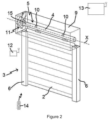
- FIG. 1 And 2 an embodiment of a home automation installation for closing or solar protection in accordance with the invention and installed in a building comprising an opening 1, window or door, equipped with a screen 2 belonging to a concealment device 3, in particular a motorized roller shutter.
- the blackout device 3 may be a roller shutter, a canvas blind or one with adjustable slats, in particular a patio blind or a Venetian blind, a gate or a garage door.
- the present invention applies to all types of blackout device.
- the screen 2 of the occultation device 3 is wound on a winding tube 4 driven by a motorized drive device 5 and movable between a wound position, in particular high, and an unwound position, in particular low.
- the movable screen 2 of the occultation device 3 is a closing, occultation and/or solar protection screen, rolling up on the winding tube 4 whose internal diameter is substantially greater than the external diameter of an electromechanical actuator 11, so that the electromechanical actuator 11 can be inserted into the winding tube 4, during the assembly of the occultation device 3.
- the motorized drive device 5 comprises the electromechanical actuator 11, in particular of the tubular type, making it possible to rotate the winding tube 4, so as to unwind or wind the screen 2 of the occulting device 3.
- the occulting device 3 comprises the winding tube 4 for winding the screen 2, where, in the mounted state, the electromechanical actuator 11 is inserted into the winding tube 4.
- the upper rolled-up position corresponds to the support of an L-shaped final end blade 8 of the apron 2 of the roller shutter 3 against an edge of a box 9 of the roller shutter 3
- the lower unrolled position corresponds to the support of the final end blade 8 of the apron 2 of the roller shutter 3 against a threshold 7 of the opening 1.
- the first blade of the apron 2 of the roller shutter 3, opposite the end blade, is connected to the winding tube 4 by means of at least one joint 10, in particular a band-shaped attachment piece.
- the winding tube 4 is arranged inside the box 9 of the roller shutter 3.
- the apron 2 of the roller shutter 3 winds and unwinds around the winding tube 4 and is housed at least partly inside the box 9.
- the trunk 9 is arranged above the opening 1, or in the upper part of the opening 1.
- the motorized drive device 5 is controlled by a control unit.
- the control unit may be, for example, a local control unit 12, where the local control unit 12 may be connected in a wired or wireless connection to a central control unit 13.
- the central control unit 13 controls the local control unit 12, as well as other similar local control units distributed throughout the building.
- the central control unit 13 may be in communication with a remote weather station outside the building, including, in particular, one or more sensors which may be configured to determine, for example, a temperature, a brightness, or even a wind speed.
- the local control unit may be a control point 12, in particular a wall-mounted one, or a remote control 14.
- the control unit 12, 14 may comprise a keyboard comprising selection elements and/or activation elements and, possibly, a display element, so as to allow a user to intervene on the electromechanical actuator 11 and/or the central control unit 13.
- the electromechanical actuator 11 can be controlled by the control point 12 by means of wireless communication.
- the electromechanical actuator 11 is preferably configured to execute the commands for unrolling or rolling up the screen 2 of the occulting device 3 which can be issued, in particular, by the control point 12 or the remote control 14.
- the control unit 12, 14 may comprise a controller and a control command transmission module.
- the control command transmission module of the control point may thus enable the transmission of commands by wireless means.
- the control command transmission module of the control unit is configured to transmit radio control commands.
- the control unit 12, 14 may also comprise a module for receiving control orders.
- control order issuing module and the control order receiving module are included in two separate modules.
- control point 12 comprises fixing elements, not shown, in particular by elastic snap-fastening.
- control point 12 is installed on a window upright of the home automation system.
- the assembly of the control point 12 on the upright is implemented by means of the fixing elements configured to cooperate with a hole provided in the upright.
- the electromechanical actuator 11 comprises an electric motor 16.
- the electric motor 16 comprises a rotor and a stator, not shown and positioned coaxially around an axis of rotation X, which is also the axis of rotation of the winding tube 4 in the mounted configuration of the motorized drive device 5.
- the electromechanical actuator 11 is supplied with electrical energy by a mains power supply network, or by means of a battery, which can be recharged, for example, by a photovoltaic panel.
- the electromechanical actuator 11 makes it possible to move the screen 2 of the occulting device 3.
- the electromechanical actuator 11 comprises an electrical power supply cable 18 allowing it to be supplied with electrical energy from the mains power supply network.
- Means for controlling the electromechanical actuator 11 according to the invention, allowing the screen 2 of the occulting device 3 to be moved comprise at least one electronic control unit 15.
- This electronic control unit 15 is capable of starting the electric motor 16 of the electromechanical actuator 11, and, in particular, of allowing the electric motor 16 to be supplied with electrical energy.
- the electronic control unit 15 controls, in particular, the electric motor 16, so as to open or close the screen 2, as described previously.
- the electronic control unit 15 also comprises a module 27 for receiving control orders, in particular electrical orders emitted by an order transmitter, such as the control point 12 and/or the remote control 14 intended to control the electromechanical actuator 11.
- the control order receiving module of the electronic control unit 15 can thus allow the reception of orders transmitted by wireless means.
- the control order receiving module of the electronic control unit 15 is configured to receive radio control orders.
- the control means of the electromechanical actuator 11 comprise hardware and/or software means.
- the hardware means may comprise at least one microcontroller integrated into the electronic control unit 15.
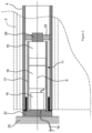
- the electronic control unit 15 is arranged, in other words integrated, inside the casing 17 of the electromechanical actuator 11.
- the electronic unit of control 15 is arranged outside the casing 17 of the electromechanical actuator 11 and, in particular, mounted on the support 23 or in the closing element 21.
- the casing 17 of the electromechanical actuator 11 is preferably cylindrical in shape.
- the electromechanical actuator 11 also comprises a gear reduction device 19 and an output shaft 20.
- the electromechanical actuator 11 may also include an end-of-travel and/or obstacle detection device, not shown, which may be mechanical and/or electronic.
- the electric motor 16 and the gear reduction device 19 are arranged inside the casing 17 of the electromechanical actuator 11.
- the output shaft 20 of the electromechanical actuator 11 is arranged inside the winding tube 4, and at least partly outside the casing 17 of the electromechanical actuator 11.
- the output shaft 20 of the electromechanical actuator 11 is coupled by a connecting element 22 to the winding tube 4, in particular a wheel-shaped connecting element.
- the electromechanical actuator 11 also comprises a closing element 21 for one end of the casing 17.
- the casing 17 of the electromechanical actuator 11 is fixed to a support 23, in particular a cheek, of the box 9 of the concealing device 3 by means of the closing element 21 forming a torque support, in particular a closing and torque recovery head.
- the closing element 21 forms a torque support
- the closing element 21 is also called a fixed point of the electromechanical actuator 11.
- the home automation installation in particular the control point 12 and the electromechanical actuator 11, in particular the controller 24 and the electronic control unit 15, comprises hardware and/or software means making it possible to govern its operation in accordance with the method which is the subject of the invention.
- the software means may, in particular, comprise a computer program code adapted to carrying out the steps of the method according to the invention, when the program is executed on a computer.
- the electronic control unit 15 is configured to be electrically connected to a polyphase rotating electrical machine, such as an electric motor 16 or an electrical energy generator 16', in order to control and/or command it.
- the electronic control unit 15 comprises a plurality of output terminals. Each output terminal is configured to be electrically connected to an input terminal of the electric motor 16.
- the electronic control unit 15 comprises a variable precision measuring device configured to estimate the value of the internal temperature of a motor electrically connected to the terminals of the electronic control unit and to deliver a signal proportional to the internal temperature of the motor electrically connected to the terminals of the electronic control unit.
- the variable precision measuring device comprises a power source, configured to deliver a continuous power electrical signal, referenced to a fixed potential reference GND, for a predetermined duration.
- the adjustable precision measuring device comprises a sensor.
- the sensor may be a current sensor configured to deliver a signal proportional to the current absorbed by the adjustable precision measuring device when at least two output terminals 150 of the electronic control unit 15 are electrically connected to input terminals 160 of the polyphase electric motor 16.
- the adjustable precision measuring device also includes an adjustment resistor R ajust whose value determines the measurement accuracy.
- the adjustment resistor can be one or more fixed value resistors and/or a variable resistor.
- the electrical power supply source, the adjustment resistor R ajust and the sensor R measure are electrically connected in series and arranged between two of the output terminals 150 of the electronic control unit 15.
- the measuring device may comprise an analog-digital converter electrically connected to the terminals of the sensor R measure. in order to detect the signal delivered by the latter and provide a sampled signal of the delivered signal.
- the analog-digital converter is an output of a microcontroller or a microprocessor. It may be, for example, an output of the control module.
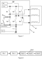
- FIG. 4 represents an exemplary embodiment of an electronic control unit 15.
- the electronic control unit 15 comprises a plurality of output terminals 150 configured to be electrically connected with the plurality of input terminals 160 of a polyphase motor.
- the electronic control unit 15 comprises three output terminals intended to be electrically connected with the three input terminals of a three-phase electric motor.
- the electric motor 16 may be a direct current electric motor, a two-phase electric motor or any other type of electric motor comprising a greater number of phases.
- the number of output terminals 150 of the electronic control unit 15 will be of the number of
- the electronic control unit 15 comprises a polyphase inverter configured to deliver, sequentially, electrical signals between two output terminals taken from among the plurality of output terminals and an adjustable precision measuring device configured to estimate the internal temperature of the electric motor electrically connected to the electronic control unit.
- a first connection point C1 of the inverter is electrically connected to a first terminal V bus of the electrical energy supply source and a second connection point C2 is electrically connected to a second terminal GND of the power source via a current sensor.
- the senor is a measuring resistor R measure (or "shunt" in English terminology).
- R measure or "shunt" in English terminology.
- V measure proportional to the value of the current absorbed by the adjustable precision measuring device.
- Each branch B1, B2, B3 of the inverter includes a midpoint electrically connected to an output terminal.
- the switching of the electronic switches K1, K2, K3, K4, K5, K6 is controlled by control signals generated by a control module (not shown) forming a predetermined control law.
- the control law is broken down into a succession of switching sequences, each sequence corresponding to a set of signals for a determined duration.
- a first electronic switch K1, K2, K3 and a second electronic switch other than its associated switch K4, K5, K6 switches from its state blocking to its on state, at least one of the windings E1, E2 and E3 of the motor is supplied.
- the control law is programmed so that the inverter delivers, sequentially, a voltage between two output terminals taken from among the plurality of output terminals 150 of the electronic control unit 15.
- the electrical signals delivered by the inverter are programmed to sequentially power the stator windings of the polyphase electric motor in order to generate a rotating electric field capable of driving the rotor in rotation.
- An analog-to-digital converter is electrically connected to the sensor terminals to measure the signal proportional to the current flowing in the adjustable-precision measuring device.
- the input of the converter may be an input of a microcontroller or a microprocessor. It may be, for example, a microcontroller belonging to the control module controlling the electronic switches, K1, K2, K3, K4, K5, K6 of the inverter.
- the adjustment resistor R ajust is electrically connected in series with an electronic switch K7, called the seventh switch.
- the adjustment resistor R ajust and the seventh electronic switch K7 are electrically connected between the midpoint U of a branch B1 of the inverter and a connection point C2 of the inverter.
- the electronic switch K7 can be, for example, a transistor, a triac or any other type of equivalent electronic switch.
- the electronic switch K7 can be, for example, controlled by the control module driving the electronic switches, K1, K2, K3, K4, K5, K6 of the inverter.
- the electrical power supply source is electrically connected to a microprocessor or microcontroller, for example, an output of the control module, the microprocessor being programmed to switch the output of the power source into an on state during the predetermined time interval.
- FIG. 5 represents an example of an equivalent diagram of the system formed by the adjustable precision measuring device when a direct current flows through it and when at least one winding of an electric motor is electrically connected to its terminals.
- the direct electrical power supply source delivers a voltage V.
- the electrical power supply source Vcc of the adjustable precision measuring device and the electrical power supply source V bus of the inverter are different.
- the electrical power supply source of the adjustable precision measuring device may be a low voltage source, delivering for example, a direct voltage of the order of 12V.
- the power source of the inverter may be a high voltage source delivering a direct voltage of amplitude greater than 42V.
- the electrical power supply source of the adjustable precision measuring device is electrically connected to the midpoint of a branch of the inverter via a diode D8.
- the diode D8 is configured to only allow current to pass from the power supply source of the adjustable precision measuring device to the midpoint V of the branch to which the diode is electrically connected.
- the diode D8 makes it possible to block the current flowing back to the power supply of the adjustable precision measuring device.
- the estimation method comprises a step Etp3 of estimating the internal temperature of the motor from the signal proportional to the current flowing in the adjustable precision measuring device.
- Electric motor windings are typically made of copper, a metal whose resistance varies with temperature. Since the resistance of an electric motor's windings varies with temperature, this element can be used as a temperature sensor to estimate the internal temperature of the electric motor.
- this solution provides a signal proportional to the internal temperature of the motor without having to modify the motor or add any additional components to the motor.
- winding resistance the resistance of the powered winding(s)
- V represents the amplitude of the voltage delivered by the DC power supply.
- step Etp3 of estimating the internal temperature of the motor may comprise a sub-step Etp31 of estimating the amplitude of the current flowing in the adjustable-precision measuring device using the signal supplied by the sensor.
- the estimation step may then comprise a sub-step Etp32 of estimating the value of the winding resistance from the value of the estimated current and finally, a sub-step Etp33 of estimating the internal temperature of the motor using the value of the winding resistance.
- the present invention also relates to a method for designing an electronic control unit capable of controlling a polyphase rotating machine 16, 16' as described previously.
- the design method comprises a step of dimensioning the value of an adjustment resistor of the adjustable precision measuring device.
- the sizing step includes a first step of choosing the desired sensitivity for estimating the internal temperature of the electric motor.
- the sizing step then comprises a step of estimating the value of the total resistance of the system formed by the adjustable precision measuring device and the electric motor 16 electrically connected to said adjustable precision measuring device.
- the variation in the value of the winding resistance ⁇ R is therefore directly proportional to the variation in temperature ⁇ T.
- R g be the total resistance of the circuit at a given temperature.
- ⁇ T be the desired temperature sensitivity for the adjustable precision measuring device.
- V_bus Vdd
- Vdd-Vd Vd representing the value of the voltage drop due to diode D8.
- ⁇ I be the variation in current due to a variation in the temperature of the powered windings equal to ⁇ T.
- Solving equation (15) makes it possible to estimate the value of the total resistance of the system formed by the adjustable precision measuring device and the electric motor electrically connected to said adjustable precision measuring device.
- the value of the adjustment resistance to be placed in the adjustable precision measuring device can be deduced in order to obtain the desired sensitivity for estimating the internal temperature of the engine.
- the sizing step may then include a step of estimating the power dissipated in the adjustment resistor as well as the energy dissipated in the adjustment resistor during the predetermined measurement time.
- the electrical power supply source of the adjustable precision measuring device delivers a voltage equal to 3.3V, that at the temperature of 25°C the value of the winding resistance is equal to 0.7 ⁇ and that at the temperature of 100°C the value of the winding resistance is equal to 0.9 ⁇ .
- the current sensor is a measuring resistor with a value of 0.33 ⁇ and that the analog-to-digital converter electrically connected to the terminals of the current sensor is a 12-bit converter.
- the electronic control unit according to the invention is distinguished from a conventional polyphase motor control circuit by the adjustment resistor R ajust and the electronic switch K7.
- the addition of these two components makes it possible to obtain a precise measurement of the temperature of the windings of the motor electrically connected to the terminals of the electronic control unit.
- the choice of the value of the adjustment resistor makes it possible to define the value of the desired precision
Landscapes
- Engineering & Computer Science (AREA)
- Power Engineering (AREA)
- Physics & Mathematics (AREA)
- General Physics & Mathematics (AREA)
- Control Of Electric Motors In General (AREA)
Claims (12)
- Elektronische Steuereinheit (15), die so konfiguriert ist, dass sie eine mehrphasige rotierende elektrische Maschine (16, 16') steuert, wobei die elektronische Steuereinheit (15) eine Vielzahl von Ausgangsanschlüssen (150) umfasst, wobei jeder Ausgangsanschluss (150) so konfiguriert ist, dass er elektrisch mit einem Eingangsanschluss (160) der mehrphasigen rotierenden elektrischen Maschine (16, 16') verbunden ist, wobei die elektronische Steuereinheit dadurch gekennzeichnet ist, dass sie eine Messvorrichtung mit einstellbarer Genauigkeit umfasst, die umfasst:- eine Stromversorgungsquelle (V_bus, Vdd), die so konfiguriert ist, dass sie ein kontinuierliches Stromversorgungssignal liefert, wobei das Stromversorgungssignal während eines vorbestimmten Zeitintervalls geliefert wird,- einen Einstellwiderstand (Rajust) , der so konfiguriert ist, dass er die Genauigkeit der Messung der Messvorrichtung festlegt ,- einen Sensor (Rmesure), der so konfiguriert ist, dass er ein Signal ausgibt, das proportional zu dem Strom ist, der von der Messvorrichtung aufgenommen wird, wenn mindestens zwei der Ausgangsanschlüsse (150) der elektronischen Steuereinheit (15) elektrisch mit Eingangsanschlüssen (160) der mehrphasigen rotierenden elektrischen Maschine (16, 16') verbunden sind,wobei die elektrische Energieversorgungsquelle (V_bus, Vdd), der Einstellwiderstand (Rajust) und der Sensor (Rmesure) elektrisch in Reihe geschaltet und zwischen zwei der Ausgangsanschlüsse 150) der elektronischen Steuereinheit (15) angeordnet sind, wobei die Messvorrichtung mit einstellbarer Genauigkeit außerdem einen elektronischen Schalter (K7), den sogenannten siebten Schalter, umfasst, der so konfiguriert ist, dass er die Ausgabe des Versorgungssignals der elektrischen Energieversorgungsquelle (V_bus, Vdd) der Messvorrichtung mit einstellbarer Genauigkeit der elektronischen Steuereinheit zeitlich begrenzt.
- Elektromechanischer Aktuator, dadurch gekennzeichnet, dass er eine elektronische Steuereinheit (15) nach Anspruch 1 umfasst, die einen mehrphasigen Wechselrichter mit einer Vielzahl von Ausgangsanschlüssen (150) und eine mehrphasige rotierende elektrische Maschine (16, 16') mit einer Vielzahl von Eingangsanschlüssen (160) umfasst, wobei jeder Eingangsanschluss der rotierenden Maschine elektrisch mit einem Ausgangsanschluss der elektronischen Steuereinheit verbunden ist, wobei die elektronische Steuereinheit (15) so konfiguriert ist, dass sie die Innentemperatur der mehrphasigen rotierenden Maschine (16, 16') mithilfe der Messvorrichtung mit einstellbarer Genauigkeit schätzt.
- Elektromechanischer Aktuator nach dem vorhergehenden Anspruch, bei dem der Wert des einstellbaren Widerstands (Rajust) in Abhängigkeit von der gewünschten Genauigkeit der Messung der Messvorrichtung, von Parametern der elektrischen Energieversorgungsquelle, von Parametern des Analog-Digital-Wandlers und von Parametern der rotierenden elektrischen Maschine (16, 16') bestimmt wird.
- Elektromechanischer Aktuator nach dem vorhergehenden Anspruch, bei dem die rotierende mehrphasige elektrische Maschine ein mehrphasiger Elektromotor (16) ist.
- Elektromechanischer Aktuator nach dem vorhergehenden Anspruch, wobei der Wechselrichter eine Vielzahl von Zweigen (B1, B2, B3) aufweist, die zwischen einem ersten Verbindungspunkt (C1) und einem zweiten Verbindungspunkt (C2) elektrisch parallel geschaltet sind, wobei jeder Zweig (B1, B2, B3) einen ersten elektronischen Schalter (K1, K2, K3) aufweist, der mit dem ersten Verbindungspunkt (C1) elektrisch verbunden ist und mit einem zugehörigen zweiten elektronischen Schalter (K4, K5, K6) elektrisch in Reihe geschaltet ist, wobei der zweite elektronische Schalter elektrisch mit dem zweiten Verbindungspunkt (C2) verbunden ist und derart, dass durch das gleichzeitige Schalten eines ersten elektronischen Schalters (K1, K2, K3) und eines zweiten elektronischen Schalters (K4, K5, K6), der nicht sein zugehöriger elektronischer Schalter ist, kann mindestens eine Wicklung (E1, E2, E3) der mehrphasigen elektrischen Drehmaschine gespeist werden, wobei der siebte elektronische Schalter (K7) von einem Steuerungsmodul gesteuert wird, das auch die ersten und zweiten elektronischen Schalter (K1, K2, K3, K4, K5, K6) des Wechselrichters steuert.
- Elektromechanischer Aktuator nach dem vorhergehenden Anspruch, wobei der siebte elektronische Schalter (K7) und ein zugehöriger erster elektronischer Schalter (K2, K3) so konfiguriert sind, dass sie während eines vorbestimmten Zeitintervalls gemeinsam von einem gesperrten Zustand in einen eingeschalteten Zustand umschalten.
- Elektromechanischer Aktuator nach einem der Ansprüche 5 oder 6, bei dem die elektrische Energieversorgungsquelle der Messvorrichtung mit einstellbarer Genauigkeit elektrisch an einen Mittelpunkt (V) eines Zweigs (B1, B2, B3) des Wechselrichters angeschlossen ist, der sich von dem Zweig (B1, B2, B3) mit dem der siebte elektronische Schalter (K7) elektrisch verbunden ist, unterscheidet, über einen weiteren elektronischen Schalter (K8), den sogenannten achten Schalter, wobei dieser dazu bestimmt ist, gleichzeitig mit einem zweiten Schalter (K4, K5, K6) der Messvorrichtung mit einstellbarer Genauigkeit zu schalten.
- Elektromechanischer Stellantrieb nach einem der Ansprüche 2 bis 7, wobei die elektronische Steuereinheit (15) ein Steuermodul umfasst, das so konfiguriert ist, dass es vor jedem Startversuch der rotierenden Maschine (16, 16') die interne Motortemperatur testet und den Start der rotierenden Maschine (16, 16') nur dann zulässt, wenn die interne Temperatur der mehrphasigen rotierenden elektrischen Maschine (16, 16') unter einem vorbestimmten Schwellenwert liegt.
- Heimautomatisierungsvorrichtung, dadurch gekennzeichnet, dass sie einen Aktuator nach einem der Ansprüche 2 bis 8 umfasst.
- Motorisierungsanordnung für einen Verschluss- oder Sonnenschutzschirm, dadurch gekennzeichnet, dass sie einen elektromechanischen Aktuator nach einem der Ansprüche 2 bis 8 umfasst.
- Verfahren zur Schätzung der Innentemperatur einer mehrphasigen rotierenden elektrischen Maschine (16, 16'), die eine Vielzahl von Eingangsanschlüssen (160) und eine Vielzahl von Wicklungen (E1, E2, E3) umfasst, wobei jeder Eingangsanschluss der rotierenden Maschine elektrisch mit einem Ausgangsanschluss einer elektronischen Steuereinheit nach Anspruch 1 verbunden ist, wobei die elektronische Steuereinheit (15) außerdem eine Messvorrichtung mit einstellbarer Genauigkeit umfasst, die Folgendes umfasst:- eine Stromversorgungsquelle (V_bus, Vdd), die so konfiguriert ist, dass sie ein kontinuierliches Stromversorgungssignal liefert, wobei das Stromversorgungssignal während eines vorbestimmten Zeitintervalls geliefert wird,- einen Einstellwiderstand (R(ajust)), der so konfiguriert ist, dass er die Genauigkeit der Messung der Messvorrichtung festlegt,- einen Sensor (Rmesure), der so konfiguriert ist, dass er ein Signal ausgibt, das proportional zu dem Strom ist, der von der Messvorrichtung aufgenommen wird, wenn mindestens zwei der Ausgangsanschlüsse 150) der elektronischen Steuereinheit (15) elektrisch mit Eingangsanschlüssen (160) der mehrphasigen rotierenden elektrischen Maschine (16, 16') verbunden sind,die elektrische Energieversorgungsquelle (V_bus, Vdd), der Einstellwiderstand (R(ajust)) und der Sensor (Rmesure) elektrisch in Reihe geschaltet und zwischen zwei der Ausgangsanschlüsse (150) der elektronischen Steuereinheit (15) angeordnet sind, wobei die Messvorrichtung mit einstellbarer Genauigkeit außerdem einen elektronischen Schalter (K7), den sogenannten siebten Schalter, umfasst, der so konfiguriert ist, dass er die Ausgabe des Stromversorgungssignals der elektrischen Energiequelle (V_bus, Vdd) der Messvorrichtung mit einstellbarer Genauigkeit der elektronischen Steuereinheit zeitlich begrenzt,wobei das Verfahren dadurch gekennzeichnet ist, dass es Folgendes umfasst:- einen Schritt (Etp1) zum Aufbau einer Gleichspannung zwischen zwei Ausgangsanschlüssen (150) der elektronischen Steuereinheit (15) während eines vorbestimmten Zeitintervalls mit Hilfe der elektrischen Energieversorgungsquelle (V_bus, Vdd), wobei der Rotor während dieses Schritts nicht in Drehung versetzt wird, wobei die Messung der Innentemperatur des Motors durchgeführt wird, wenn der Motor stillsteht,- einen Schritt (Etp2) zur Lieferung eines Signals durch den Sensor (Rmesure), das repräsentativ für einen Strom ist, der von der Messvorrichtung während des vorbestimmten Zeitintervalls absorbiert wurde,- einen Schritt (Etp3) zum Schätzen der Innentemperatur der rotierenden elektrischen Maschine (16, 16') anhand des von dem Sensor (Rmesure) gelieferten Signals, wobei der Wert der Genauigkeit der Schätzung durch den Wert des Anpassungswiderstands (Rajust) definiert ist.
- Verfahren nach dem vorhergehenden Anspruch, wobei der Schritt (Etp3) zum Schätzen der Innentemperatur umfasst :- einen Unterschritt (Etp31) zum Schätzen der Amplitude eines Stroms, der in der Messvorrichtung mit einstellbarer Genauigkeit fließt, mithilfe des Signals, das von dem Sensor (Rmesure) geliefert wird,- einen Unterschritt (Etp32) zum Schätzen des Werts des Widerstands (Renroul) von mindestens einer Wicklung (E1, E2, E3) der rotierenden Maschine (16, 16') anhand des Werts des geschätzten Stroms,- einen Unterschritt (Etp33) zum Schätzen der Innentemperatur der rotierenden elektrischen Maschine (16, 16') mithilfe des Werts des Widerstands (Renroul)von mindestens einer Wicklung (E1, E2, E3).
Applications Claiming Priority (2)
| Application Number | Priority Date | Filing Date | Title |
|---|---|---|---|
| FR1771385A FR3075514B1 (fr) | 2017-12-18 | 2017-12-18 | Procede d’estimation de la temperature interne d’une machine tournante , unite electronique de controle, actionneur et dispositif domotique associes |
| PCT/EP2018/085465 WO2019121662A1 (fr) | 2017-12-18 | 2018-12-18 | Procede d'estimation de la temperature interne d'une machine tournante, unite electronique de controle, actionneur et dispositif domotique associes |
Publications (2)
| Publication Number | Publication Date |
|---|---|
| EP3729638A1 EP3729638A1 (de) | 2020-10-28 |
| EP3729638B1 true EP3729638B1 (de) | 2025-04-30 |
Family
ID=63079948
Family Applications (1)
| Application Number | Title | Priority Date | Filing Date |
|---|---|---|---|
| EP18819126.6A Active EP3729638B1 (de) | 2017-12-18 | 2018-12-18 | Verfahren zur schätzung der innentemperatur einer drehmaschine, zugehörige elektronisch steuereinheit, aktuator und heimautomatisierungsvorrichtung |
Country Status (3)
| Country | Link |
|---|---|
| EP (1) | EP3729638B1 (de) |
| FR (1) | FR3075514B1 (de) |
| WO (1) | WO2019121662A1 (de) |
Cited By (1)
| Publication number | Priority date | Publication date | Assignee | Title |
|---|---|---|---|---|
| US7730864B2 (en) | 2006-05-05 | 2010-06-08 | Olaf Toedter | Method of operating glow plugs in diesel engines |
Families Citing this family (1)
| Publication number | Priority date | Publication date | Assignee | Title |
|---|---|---|---|---|
| DE102020113770A1 (de) | 2020-05-20 | 2021-11-25 | Dormakaba Deutschland Gmbh | Verfahren zur Bestimmung der Temperatur einer Motorwicklung eines Elektromotors |
Family Cites Families (3)
| Publication number | Priority date | Publication date | Assignee | Title |
|---|---|---|---|---|
| JP4501433B2 (ja) * | 2003-10-24 | 2010-07-14 | ダイキン工業株式会社 | Dcモータのコイル温度推定方法およびその装置 |
| US8084984B2 (en) * | 2008-12-22 | 2011-12-27 | Eaton Corporation | System and method for monitoring and controlling stator winding temperature in a de-energized AC motor |
| GB201222284D0 (en) * | 2012-12-11 | 2013-01-23 | Nidec Sr Drives Ltd | Estimation of resistance in electrical machines |
-
2017
- 2017-12-18 FR FR1771385A patent/FR3075514B1/fr active Active
-
2018
- 2018-12-18 WO PCT/EP2018/085465 patent/WO2019121662A1/fr not_active Ceased
- 2018-12-18 EP EP18819126.6A patent/EP3729638B1/de active Active
Cited By (1)
| Publication number | Priority date | Publication date | Assignee | Title |
|---|---|---|---|---|
| US7730864B2 (en) | 2006-05-05 | 2010-06-08 | Olaf Toedter | Method of operating glow plugs in diesel engines |
Also Published As
| Publication number | Publication date |
|---|---|
| WO2019121662A1 (fr) | 2019-06-27 |
| FR3075514B1 (fr) | 2020-10-23 |
| FR3075514A1 (fr) | 2019-06-21 |
| EP3729638A1 (de) | 2020-10-28 |
Similar Documents
| Publication | Publication Date | Title |
|---|---|---|
| EP3433446B1 (de) | Verfahren zur konfigurierung und steuerung des betriebs einer motorisierten antriebsvorrichtung für eine heimautomatisierungseinheit sowie zugehörige einheit und motorisierte antriebsvorrichtung | |
| EP4232680B1 (de) | Verfahren zur steuerung des betriebs einer beschattungsvorrichtung und zugehörige beschattungsvorrichtung | |
| EP3283721B1 (de) | Motorisierte antriebsvorrichtung für eine schliess- oder sonnenschutz-heimautomatisierungsanlage, zugehörige heimautomatisierungsanlage und verfahren zur steuerung des betriebs solch einer vorrichtung | |
| EP3504393B1 (de) | Motorisierte antriebsvorrichtung für eine schliess- oder sonnenschutzeinheit und entsprechende einheit | |
| WO2016012566A1 (fr) | Procédé de commande en fonctionnement d'un dispositif d'entraînement motorisé d'une installation domotique de fermeture ou de protection solaire et dispositif associé | |
| EP3292262B1 (de) | Verfahren zur konfigurierung und steuerung des betriebs einer motorisierten antriebsvorrichtung für eine heimautomatisierungseinheit sowie zugehörige einheit und motorisierte antriebsvorrichtung | |
| FR3088362A1 (fr) | Procede de commande en fonctionnement d'une installation domotique de fermeture, d'occultation ou de protection solaire et installation domotique associee | |
| WO2019121662A1 (fr) | Procede d'estimation de la temperature interne d'une machine tournante, unite electronique de controle, actionneur et dispositif domotique associes | |
| EP3303752A1 (de) | Verfahren zur konfiguration einer motorantriebsvorrichtung für eine hausautomatisierungseinheit und zugehörige einheit und motorantriebsvorrichtung | |
| EP4175116A1 (de) | Motorisierte antriebsvorrichtung, verdunkelungsvorrichtung und steuerungsverfahren dafür | |
| EP4175119B1 (de) | Motorisierte antriebsvorrichtung, verdunkelungsvorrichtung und steuerungsverfahren dafür | |
| EP4530432B1 (de) | Verfahren zur betriebssteuerung einer motorischen antriebsvorrichtung, motorisierte antriebsvorrichtung und verdunkelungsvorrichtung dafür | |
| EP3312689B1 (de) | Verfahren zur betriebssteuerung einer domotik-anlage, und entsprechende domotik-anlage | |
| FR3139592A1 (fr) | Dispositif d’entraînement motorisé d’un dispositif d’occultation et dispositif d’occultation associé | |
| FR3118643A1 (fr) | Dispositif d’entraînement motorisé pour un dispositif d’occultation, dispositif d’occultation et procédé de commande en fonctionnement associés | |
| EP3954857B1 (de) | Abdeckvorrichtung, die eine motorisierte antriebsvorrichtung umfasst | |
| WO2024141725A1 (fr) | Dispositif et procede de controle d'un moteur electrique avec une loi de commande de type pas a pas | |
| WO2024141726A1 (fr) | Dispositif et procédé de contrôle d'un moteur électrique prenant en compte un environnement mécanique du moteur | |
| EP4704313A1 (de) | Elektromechanischer aktuator und verdunkelungsvorrichtung mit solch einem elektromechanischen aktuator | |
| EP3910780A1 (de) | Stromversorgungsvorrichtung, elektromechanisches stellglied, das eine solche stromversorgungsvorrichtung umfasst, und schliess- , verdunkelungs- oder sonnenschutzanlage, die ein solches elektromechanisches stellglied umfasst | |
| FR3088952A1 (fr) | Procédé de commande en fonctionnement d’une installation domotique de fermeture, d’occultation ou de protection solaire et installation domotique associée | |
| FR3093753A1 (fr) | Accessoire de montage d’un actionneur électromécanique pour une installation de fermeture, d’occultation ou de protection solaire sur un bâti et installation associée |
Legal Events
| Date | Code | Title | Description |
|---|---|---|---|
| STAA | Information on the status of an ep patent application or granted ep patent |
Free format text: STATUS: UNKNOWN |
|
| STAA | Information on the status of an ep patent application or granted ep patent |
Free format text: STATUS: THE INTERNATIONAL PUBLICATION HAS BEEN MADE |
|
| PUAI | Public reference made under article 153(3) epc to a published international application that has entered the european phase |
Free format text: ORIGINAL CODE: 0009012 |
|
| STAA | Information on the status of an ep patent application or granted ep patent |
Free format text: STATUS: REQUEST FOR EXAMINATION WAS MADE |
|
| 17P | Request for examination filed |
Effective date: 20200616 |
|
| AK | Designated contracting states |
Kind code of ref document: A1 Designated state(s): AL AT BE BG CH CY CZ DE DK EE ES FI FR GB GR HR HU IE IS IT LI LT LU LV MC MK MT NL NO PL PT RO RS SE SI SK SM TR |
|
| AX | Request for extension of the european patent |
Extension state: BA ME |
|
| DAV | Request for validation of the european patent (deleted) | ||
| DAX | Request for extension of the european patent (deleted) | ||
| STAA | Information on the status of an ep patent application or granted ep patent |
Free format text: STATUS: EXAMINATION IS IN PROGRESS |
|
| 17Q | First examination report despatched |
Effective date: 20211028 |
|
| GRAP | Despatch of communication of intention to grant a patent |
Free format text: ORIGINAL CODE: EPIDOSNIGR1 |
|
| STAA | Information on the status of an ep patent application or granted ep patent |
Free format text: STATUS: GRANT OF PATENT IS INTENDED |
|
| RIC1 | Information provided on ipc code assigned before grant |
Ipc: H02P 29/60 20160101ALI20240930BHEP Ipc: H02H 7/08 20060101ALI20240930BHEP Ipc: H02H 7/06 20060101ALI20240930BHEP Ipc: G01K 7/16 20060101ALI20240930BHEP Ipc: H02P 29/02 20160101ALI20240930BHEP Ipc: H02P 29/64 20160101AFI20240930BHEP |
|
| INTG | Intention to grant announced |
Effective date: 20241031 |
|
| GRAS | Grant fee paid |
Free format text: ORIGINAL CODE: EPIDOSNIGR3 |
|
| GRAA | (expected) grant |
Free format text: ORIGINAL CODE: 0009210 |
|
| STAA | Information on the status of an ep patent application or granted ep patent |
Free format text: STATUS: THE PATENT HAS BEEN GRANTED |
|
| AK | Designated contracting states |
Kind code of ref document: B1 Designated state(s): AL AT BE BG CH CY CZ DE DK EE ES FI FR GB GR HR HU IE IS IT LI LT LU LV MC MK MT NL NO PL PT RO RS SE SI SK SM TR |
|
| REG | Reference to a national code |
Ref country code: CH Ref legal event code: EP Ref country code: GB Ref legal event code: FG4D Free format text: NOT ENGLISH |
|
| REG | Reference to a national code |
Ref country code: DE Ref legal event code: R096 Ref document number: 602018081565 Country of ref document: DE |
|
| REG | Reference to a national code |
Ref country code: IE Ref legal event code: FG4D Free format text: LANGUAGE OF EP DOCUMENT: FRENCH |
|
| REG | Reference to a national code |
Ref country code: NL Ref legal event code: MP Effective date: 20250430 |
|
| REG | Reference to a national code |
Ref country code: AT Ref legal event code: MK05 Ref document number: 1791041 Country of ref document: AT Kind code of ref document: T Effective date: 20250430 |
|
| PG25 | Lapsed in a contracting state [announced via postgrant information from national office to epo] |
Ref country code: FI Free format text: LAPSE BECAUSE OF FAILURE TO SUBMIT A TRANSLATION OF THE DESCRIPTION OR TO PAY THE FEE WITHIN THE PRESCRIBED TIME-LIMIT Effective date: 20250430 Ref country code: ES Free format text: LAPSE BECAUSE OF FAILURE TO SUBMIT A TRANSLATION OF THE DESCRIPTION OR TO PAY THE FEE WITHIN THE PRESCRIBED TIME-LIMIT Effective date: 20250430 Ref country code: PT Free format text: LAPSE BECAUSE OF FAILURE TO SUBMIT A TRANSLATION OF THE DESCRIPTION OR TO PAY THE FEE WITHIN THE PRESCRIBED TIME-LIMIT Effective date: 20250901 |
|
| REG | Reference to a national code |
Ref country code: LT Ref legal event code: MG9D |
|
| PG25 | Lapsed in a contracting state [announced via postgrant information from national office to epo] |
Ref country code: NO Free format text: LAPSE BECAUSE OF FAILURE TO SUBMIT A TRANSLATION OF THE DESCRIPTION OR TO PAY THE FEE WITHIN THE PRESCRIBED TIME-LIMIT Effective date: 20250730 Ref country code: GR Free format text: LAPSE BECAUSE OF FAILURE TO SUBMIT A TRANSLATION OF THE DESCRIPTION OR TO PAY THE FEE WITHIN THE PRESCRIBED TIME-LIMIT Effective date: 20250731 |
|
| PG25 | Lapsed in a contracting state [announced via postgrant information from national office to epo] |
Ref country code: NL Free format text: LAPSE BECAUSE OF FAILURE TO SUBMIT A TRANSLATION OF THE DESCRIPTION OR TO PAY THE FEE WITHIN THE PRESCRIBED TIME-LIMIT Effective date: 20250430 Ref country code: PL Free format text: LAPSE BECAUSE OF FAILURE TO SUBMIT A TRANSLATION OF THE DESCRIPTION OR TO PAY THE FEE WITHIN THE PRESCRIBED TIME-LIMIT Effective date: 20250430 |
|
| PG25 | Lapsed in a contracting state [announced via postgrant information from national office to epo] |
Ref country code: BG Free format text: LAPSE BECAUSE OF FAILURE TO SUBMIT A TRANSLATION OF THE DESCRIPTION OR TO PAY THE FEE WITHIN THE PRESCRIBED TIME-LIMIT Effective date: 20250430 |
|
| PG25 | Lapsed in a contracting state [announced via postgrant information from national office to epo] |
Ref country code: HR Free format text: LAPSE BECAUSE OF FAILURE TO SUBMIT A TRANSLATION OF THE DESCRIPTION OR TO PAY THE FEE WITHIN THE PRESCRIBED TIME-LIMIT Effective date: 20250430 |
|
| PG25 | Lapsed in a contracting state [announced via postgrant information from national office to epo] |
Ref country code: AT Free format text: LAPSE BECAUSE OF FAILURE TO SUBMIT A TRANSLATION OF THE DESCRIPTION OR TO PAY THE FEE WITHIN THE PRESCRIBED TIME-LIMIT Effective date: 20250430 |
|
| PG25 | Lapsed in a contracting state [announced via postgrant information from national office to epo] |
Ref country code: RS Free format text: LAPSE BECAUSE OF FAILURE TO SUBMIT A TRANSLATION OF THE DESCRIPTION OR TO PAY THE FEE WITHIN THE PRESCRIBED TIME-LIMIT Effective date: 20250731 |
|
| PG25 | Lapsed in a contracting state [announced via postgrant information from national office to epo] |
Ref country code: IS Free format text: LAPSE BECAUSE OF FAILURE TO SUBMIT A TRANSLATION OF THE DESCRIPTION OR TO PAY THE FEE WITHIN THE PRESCRIBED TIME-LIMIT Effective date: 20250830 |
|
| PG25 | Lapsed in a contracting state [announced via postgrant information from national office to epo] |
Ref country code: LV Free format text: LAPSE BECAUSE OF FAILURE TO SUBMIT A TRANSLATION OF THE DESCRIPTION OR TO PAY THE FEE WITHIN THE PRESCRIBED TIME-LIMIT Effective date: 20250430 |
|
| PGFP | Annual fee paid to national office [announced via postgrant information from national office to epo] |
Ref country code: DE Payment date: 20251127 Year of fee payment: 8 |
|
| PG25 | Lapsed in a contracting state [announced via postgrant information from national office to epo] |
Ref country code: DK Free format text: LAPSE BECAUSE OF FAILURE TO SUBMIT A TRANSLATION OF THE DESCRIPTION OR TO PAY THE FEE WITHIN THE PRESCRIBED TIME-LIMIT Effective date: 20250430 Ref country code: SM Free format text: LAPSE BECAUSE OF FAILURE TO SUBMIT A TRANSLATION OF THE DESCRIPTION OR TO PAY THE FEE WITHIN THE PRESCRIBED TIME-LIMIT Effective date: 20250430 |
|
| PGFP | Annual fee paid to national office [announced via postgrant information from national office to epo] |
Ref country code: FR Payment date: 20251021 Year of fee payment: 8 |
|
| PG25 | Lapsed in a contracting state [announced via postgrant information from national office to epo] |
Ref country code: CZ Free format text: LAPSE BECAUSE OF FAILURE TO SUBMIT A TRANSLATION OF THE DESCRIPTION OR TO PAY THE FEE WITHIN THE PRESCRIBED TIME-LIMIT Effective date: 20250430 |
|
| PG25 | Lapsed in a contracting state [announced via postgrant information from national office to epo] |
Ref country code: EE Free format text: LAPSE BECAUSE OF FAILURE TO SUBMIT A TRANSLATION OF THE DESCRIPTION OR TO PAY THE FEE WITHIN THE PRESCRIBED TIME-LIMIT Effective date: 20250430 |
|
| PG25 | Lapsed in a contracting state [announced via postgrant information from national office to epo] |
Ref country code: RO Free format text: LAPSE BECAUSE OF FAILURE TO SUBMIT A TRANSLATION OF THE DESCRIPTION OR TO PAY THE FEE WITHIN THE PRESCRIBED TIME-LIMIT Effective date: 20250430 Ref country code: SK Free format text: LAPSE BECAUSE OF FAILURE TO SUBMIT A TRANSLATION OF THE DESCRIPTION OR TO PAY THE FEE WITHIN THE PRESCRIBED TIME-LIMIT Effective date: 20250430 |
|
| PG25 | Lapsed in a contracting state [announced via postgrant information from national office to epo] |
Ref country code: IT Free format text: LAPSE BECAUSE OF FAILURE TO SUBMIT A TRANSLATION OF THE DESCRIPTION OR TO PAY THE FEE WITHIN THE PRESCRIBED TIME-LIMIT Effective date: 20250430 |
|
| REG | Reference to a national code |
Ref country code: DE Ref legal event code: R097 Ref document number: 602018081565 Country of ref document: DE |
|
| PLBE | No opposition filed within time limit |
Free format text: ORIGINAL CODE: 0009261 |
|
| STAA | Information on the status of an ep patent application or granted ep patent |
Free format text: STATUS: NO OPPOSITION FILED WITHIN TIME LIMIT |
|
| REG | Reference to a national code |
Ref country code: CH Ref legal event code: L10 Free format text: ST27 STATUS EVENT CODE: U-0-0-L10-L00 (AS PROVIDED BY THE NATIONAL OFFICE) Effective date: 20260311 |
|
| 26N | No opposition filed |
Effective date: 20260202 |