EP3729137B1 - Multipuls-lidarsystem zur mehrdimensionalen erfassung von objekten - Google Patents
Multipuls-lidarsystem zur mehrdimensionalen erfassung von objekten Download PDFInfo
- Publication number
- EP3729137B1 EP3729137B1 EP18826568.0A EP18826568A EP3729137B1 EP 3729137 B1 EP3729137 B1 EP 3729137B1 EP 18826568 A EP18826568 A EP 18826568A EP 3729137 B1 EP3729137 B1 EP 3729137B1
- Authority
- EP
- European Patent Office
- Prior art keywords
- scanning
- pixel
- macro
- subdetectors
- assigned
- Prior art date
- Legal status (The legal status is an assumption and is not a legal conclusion. Google has not performed a legal analysis and makes no representation as to the accuracy of the status listed.)
- Active
Links
- 238000001514 detection method Methods 0.000 title claims description 98
- 238000005259 measurement Methods 0.000 claims description 77
- 238000000034 method Methods 0.000 claims description 22
- 230000005540 biological transmission Effects 0.000 claims description 17
- 238000006073 displacement reaction Methods 0.000 claims description 15
- 239000007787 solid Substances 0.000 claims description 5
- 230000002123 temporal effect Effects 0.000 claims description 4
- 238000011156 evaluation Methods 0.000 claims description 2
- 230000000750 progressive effect Effects 0.000 claims 2
- 238000005070 sampling Methods 0.000 description 29
- 230000000875 corresponding effect Effects 0.000 description 16
- 238000010586 diagram Methods 0.000 description 4
- 230000003287 optical effect Effects 0.000 description 4
- 230000005855 radiation Effects 0.000 description 3
- 238000001161 time-correlated single photon counting Methods 0.000 description 3
- 230000003213 activating effect Effects 0.000 description 2
- 238000003384 imaging method Methods 0.000 description 2
- 239000011159 matrix material Substances 0.000 description 2
- 238000012634 optical imaging Methods 0.000 description 2
- 230000004913 activation Effects 0.000 description 1
- 238000013459 approach Methods 0.000 description 1
- 230000001276 controlling effect Effects 0.000 description 1
- 238000012937 correction Methods 0.000 description 1
- 230000001419 dependent effect Effects 0.000 description 1
- 238000009532 heart rate measurement Methods 0.000 description 1
- 230000005693 optoelectronics Effects 0.000 description 1
- 230000000717 retained effect Effects 0.000 description 1
- 238000000926 separation method Methods 0.000 description 1
Images


Classifications
-
- G—PHYSICS
- G01—MEASURING; TESTING
- G01S—RADIO DIRECTION-FINDING; RADIO NAVIGATION; DETERMINING DISTANCE OR VELOCITY BY USE OF RADIO WAVES; LOCATING OR PRESENCE-DETECTING BY USE OF THE REFLECTION OR RERADIATION OF RADIO WAVES; ANALOGOUS ARRANGEMENTS USING OTHER WAVES
- G01S17/00—Systems using the reflection or reradiation of electromagnetic waves other than radio waves, e.g. lidar systems
- G01S17/88—Lidar systems specially adapted for specific applications
- G01S17/89—Lidar systems specially adapted for specific applications for mapping or imaging
-
- G—PHYSICS
- G01—MEASURING; TESTING
- G01S—RADIO DIRECTION-FINDING; RADIO NAVIGATION; DETERMINING DISTANCE OR VELOCITY BY USE OF RADIO WAVES; LOCATING OR PRESENCE-DETECTING BY USE OF THE REFLECTION OR RERADIATION OF RADIO WAVES; ANALOGOUS ARRANGEMENTS USING OTHER WAVES
- G01S17/00—Systems using the reflection or reradiation of electromagnetic waves other than radio waves, e.g. lidar systems
- G01S17/02—Systems using the reflection of electromagnetic waves other than radio waves
- G01S17/06—Systems determining position data of a target
- G01S17/08—Systems determining position data of a target for measuring distance only
- G01S17/10—Systems determining position data of a target for measuring distance only using transmission of interrupted, pulse-modulated waves
-
- G—PHYSICS
- G01—MEASURING; TESTING
- G01S—RADIO DIRECTION-FINDING; RADIO NAVIGATION; DETERMINING DISTANCE OR VELOCITY BY USE OF RADIO WAVES; LOCATING OR PRESENCE-DETECTING BY USE OF THE REFLECTION OR RERADIATION OF RADIO WAVES; ANALOGOUS ARRANGEMENTS USING OTHER WAVES
- G01S17/00—Systems using the reflection or reradiation of electromagnetic waves other than radio waves, e.g. lidar systems
- G01S17/02—Systems using the reflection of electromagnetic waves other than radio waves
- G01S17/06—Systems determining position data of a target
- G01S17/42—Simultaneous measurement of distance and other co-ordinates
-
- G—PHYSICS
- G01—MEASURING; TESTING
- G01S—RADIO DIRECTION-FINDING; RADIO NAVIGATION; DETERMINING DISTANCE OR VELOCITY BY USE OF RADIO WAVES; LOCATING OR PRESENCE-DETECTING BY USE OF THE REFLECTION OR RERADIATION OF RADIO WAVES; ANALOGOUS ARRANGEMENTS USING OTHER WAVES
- G01S17/00—Systems using the reflection or reradiation of electromagnetic waves other than radio waves, e.g. lidar systems
- G01S17/88—Lidar systems specially adapted for specific applications
- G01S17/93—Lidar systems specially adapted for specific applications for anti-collision purposes
- G01S17/931—Lidar systems specially adapted for specific applications for anti-collision purposes of land vehicles
-
- G—PHYSICS
- G01—MEASURING; TESTING
- G01S—RADIO DIRECTION-FINDING; RADIO NAVIGATION; DETERMINING DISTANCE OR VELOCITY BY USE OF RADIO WAVES; LOCATING OR PRESENCE-DETECTING BY USE OF THE REFLECTION OR RERADIATION OF RADIO WAVES; ANALOGOUS ARRANGEMENTS USING OTHER WAVES
- G01S7/00—Details of systems according to groups G01S13/00, G01S15/00, G01S17/00
- G01S7/48—Details of systems according to groups G01S13/00, G01S15/00, G01S17/00 of systems according to group G01S17/00
- G01S7/481—Constructional features, e.g. arrangements of optical elements
- G01S7/4816—Constructional features, e.g. arrangements of optical elements of receivers alone
-
- G—PHYSICS
- G01—MEASURING; TESTING
- G01S—RADIO DIRECTION-FINDING; RADIO NAVIGATION; DETERMINING DISTANCE OR VELOCITY BY USE OF RADIO WAVES; LOCATING OR PRESENCE-DETECTING BY USE OF THE REFLECTION OR RERADIATION OF RADIO WAVES; ANALOGOUS ARRANGEMENTS USING OTHER WAVES
- G01S7/00—Details of systems according to groups G01S13/00, G01S15/00, G01S17/00
- G01S7/48—Details of systems according to groups G01S13/00, G01S15/00, G01S17/00 of systems according to group G01S17/00
- G01S7/483—Details of pulse systems
- G01S7/486—Receivers
- G01S7/4861—Circuits for detection, sampling, integration or read-out
- G01S7/4863—Detector arrays, e.g. charge-transfer gates
-
- G—PHYSICS
- G01—MEASURING; TESTING
- G01S—RADIO DIRECTION-FINDING; RADIO NAVIGATION; DETERMINING DISTANCE OR VELOCITY BY USE OF RADIO WAVES; LOCATING OR PRESENCE-DETECTING BY USE OF THE REFLECTION OR RERADIATION OF RADIO WAVES; ANALOGOUS ARRANGEMENTS USING OTHER WAVES
- G01S7/00—Details of systems according to groups G01S13/00, G01S15/00, G01S17/00
- G01S7/48—Details of systems according to groups G01S13/00, G01S15/00, G01S17/00 of systems according to group G01S17/00
- G01S7/483—Details of pulse systems
- G01S7/486—Receivers
- G01S7/4865—Time delay measurement, e.g. time-of-flight measurement, time of arrival measurement or determining the exact position of a peak
Definitions
- the invention relates to a multi-pulse lidar system for multi-dimensional detection of objects in an observation area of the multi-pulse lidar system.
- the invention further relates to a method for multidimensional detection of objects in an observation area using a corresponding multipulse lidar system.
- Lidar systems are used, among other things, to detect objects in the vicinity of vehicles.
- a lidar system scans its surroundings using pulsed or time-modulated laser radiation, with the light radiation emitted by a laser source of the lidar system being reflected or scattered by objects in the surroundings and received again by means of a detector in the lidar system.
- the laser beam is successively moved along a scanning direction, whereby the objects located in the relevant observation area are detected.
- the relative position of a detected object in relation to the vehicle is determined by the corresponding angle of the laser beam and the distance information determined by measuring the transit time of the individual laser pulses.
- the lidar system can be designed in the form of a single-pulse lidar system or a multi-pulse lidar system.
- a single-pulse lidar system scans each sampling point using a single laser pulse. This makes it possible to achieve a particularly high lateral resolution.
- the system requires individual laser pulses with a relatively high laser power, which is why a correspondingly powerful laser source is required.
- the multi-pulse lidar system in which a sampling point is scanned using several individual laser pulses of lower power in quick succession, comes with a significantly lower laser power.
- a suitable detector signal With a sufficient signal-to-noise ratio results.
- the disadvantage of this method is a reduction in the lateral resolution, which is caused by adding up the individual measurements over a relatively large angular range and the associated smearing of the detector signal.
- a multipulse lidar system for detecting objects in an observation area.
- the lidar system includes a transmitting device with at least one laser source for generating a transmitting laser beam from a temporal sequence of individual laser pulses, each of which illuminates a detection area limited to a part of the observation area and scans it in at least one scanning point.
- the lidar system comprises a receiving device with a detection surface comprising a line or matrix-shaped subdetector arrangement made up of a plurality of subdetectors arranged next to one another in a first extension direction for receiving the transmitted laser beam reflected and/or scattered on objects in the observation area of the multipulse lidar system in the form of a reception laser beam.
- the receiving device is designed to image a scanning point detected by the transmitting laser beam on the detection surface in the form of an image point.
- the lidar system includes a scanning device for generating a scanning movement of the transmitting laser beam in a scanning direction to successively scan the entire observation area along several scanning points that follow one another in the scanning direction.
- the scanning movement of the transmitting laser beam is designed to include one pixel Successive individual laser pulses are each shifted along the line or matrix-shaped subdetector arrangement on the detection surface to depict.
- the lidar system comprises a control device for determining distance information of the scanning points based on the transit times of the respective individual laser pulses, the control device being designed to provide sub-detectors, which are detected by an image point currently imaged on the detection surface, together in the form of a macro which is individually assigned to the respective image point. to evaluate pixels. Due to the possibility of individually assigning subdetectors to a macro-pixel, the position of the respective macro-pixel can be optimally adapted to the position of the image point representing the image of the respective scanning point on the detection surface. This means that the measuring energy of the respective scanning point can be used optimally.
- control device is further designed to adapt the position of a macro-pixel on the detection area by regrouping corresponding subdetectors following the displacement of the image point assigned to the respective macro-pixel on the detection area caused by the scanning movement. This allows the measurement energy and measurement time of the respective sampling point to be optimally used over several individual measurements.
- the transmitting device is designed to generate a transmitting laser beam, the individual laser pulses of which each illuminate a solid angle with at least two scanning points.
- the receiving device is designed to display the two scanning points in the scanning area currently illuminated by the transmitting laser beam in the form of two image points arranged next to one another on the detection surface and shifting along the line or matrix-shaped subdetector arrangement as a result of the scanning movement.
- the control device is designed to group subdetectors which are currently detected by a first pixel of the two pixels together into a first macro-pixel assigned to the first pixel and to group together subdetectors which are currently detected by a second pixel of the two pixels to group a second macro pixel assigned to the second pixel.
- control device (130) is designed to have subdetectors which are detected by the first image point in a first individual measurement carried out by means of a first individual laser pulse and by the second image point in a second individual measurement carried out by means of a second individual laser pulse immediately following the first individual laser pulse , to be assigned to the first macro pixel in the first individual measurement and to the second macro pixel in the subsequent second individual measurement. This makes optimal use of the detection area.
- the transmitting device comprises a plurality of laser sources, the detection areas of which are arranged one above the other orthogonally to the scanning direction.
- the detection surface for each laser source includes a subdetector arrangement individually assigned to the respective laser source, the subdetector arrangements being arranged one below the other orthogonally to the scanning direction. This allows the vertical resolution of the lidar system to be increased.
- a method for multidimensional detection of objects in an observation area using a multipulse lidar system is also provided.
- the transmitting laser beam is generated in the form of a temporal sequence of individual laser pulses, with the transmitting laser beam illuminating a detection area limited to a portion of the observation area with each individual laser pulse and thereby scanning in at least one scanning point.
- a scanning movement of the transmitting laser beam is then generated in a scanning direction, which causes a successive scanning of the entire observation area in several scanning points following one another in the scanning direction.
- a reception laser beam generated by reflection and/or scattering of the transmission laser beam on objects in the observation area is received on a detection surface with a line or matrix-shaped subdetector arrangement consisting of several subdetectors arranged next to one another in a first extension direction, with a scanning point currently detected by the transmission laser beam on the detection surface in the form an image point which gradually shifts along the line or matrix-shaped subdetector arrangement as a result of the scanning movement of the transmitting laser beam is imaged.
- subdetectors whose positions correspond to the current position of the pixel become one of the respective pixels individually assigned macro pixels.
- the subdetectors assigned to the respective macro pixel are evaluated together.
- the position of the respective macro-pixel can be optimally adapted to the position of the image point representing the image of the respective scanning point on the detection surface. This means that the measuring energy of the respective scanning point can be used optimally.
- the signals measured in several individual measurements for a specific macro-pixel of the subdetectors assigned to the respective macro-pixel in these individual measurements are jointly assigned to a histogram assigned to the respective macro-pixel. This means that the measurement time from the individual measurements is evaluated together, which in particular leads to a better signal-to-noise ratio.
- the position of a macro-pixel on the detection area is successively adjusted by regrouping corresponding subdetectors following a shift of the image point assigned to the respective macro-pixel on the detection area caused by the scanning movement. This allows the measurement energy and measurement time of the respective sampling point to be optimally used across several individual measurements.
- sampling points are recorded simultaneously during an individual measurement, with subdetectors, which are recorded by a first image point generated by a first sampling point on the detection surface, being assigned to a first macro-pixel individually assigned to the first sampling point. Furthermore, subdetectors, which are detected by a second image point formed by a second scanning point on the detection surface, are assigned to a second macropixel individually assigned to the second scanning point.
- Subdetectors which are detected by the first image point during a first individual measurement and by the second image point during a second individual measurement carried out by means of a second individual laser pulse immediately following the first individual laser pulse, in the first individual measurement the first macro-pixel and in the subsequent second individual measurement assigned to the second macro pixel. This enables particularly optimal use of the detection area, which also allows particularly flexible measurement.
- the core of the invention is to enable a multi-pulse lidar system or macro scanner system which, despite using several pulses for a measurement, achieves the same lateral resolution as a single-pulse lidar system. Since a multipulse lidar system is used to improve measurement accuracy or Due to the use of special detectors or measuring principles (SPAD/TCSPC) a measurement is made up of several individual pulses, the resolution of the system without suitable compensation is limited to the angular difference between the emission of the first and the last individual laser pulse for the measurement.
- SPAD/TCSPC special detectors or measuring principles
- a row or an array of several small detectors or subdetectors is used to receive the measurement pulses instead of a single detector.
- the rotation or scanning movement can be compensated for by appropriately combining or grouping the subdetectors into macro pixels.
- the speed of regrouping the subdetectors results directly from the rotation speed of the sensor.
- the lateral resolution of such a setup then corresponds to the resolution of a single pulse solution. Furthermore, no measurement energy or measurement time is lost due to the parallel assignment of the individual laser pulses to neighboring macro pixels.
- an arrangement of several small detectors arranged in a row or matrix is used to receive individual measurement pulses instead of a single detector.
- the rotational movement of the sensor head is compensated for.
- the speed of this regrouping of the subdetectors results directly from the rotational speed of the sensor.
- the lateral resolution of such a setup corresponds to a single-pulse solution.
- Detectors that work according to different measurement principles can be used as subdetectors, for example SPAD (single photon avalanche photodiode) or TCSPC (time correlated single photon counting).
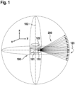
- the Figure 1 shows a macro lidar system 100 with a rotating sensor head 101, which has several transmitting and receiving units arranged at different angles, with only the transmitting device 110 being shown in the present example.
- the sensor head 101 carries out a rotating scanning movement 122, with the axis of rotation 102 running parallel to the Z axis in the present example.
- the horizontal image resolution of the lidar system is determined by the rotational movement and the measurement rate is determined.
- the vertical image resolution is defined by the number and the respective angular distance of the receiving units.
- the sensor head 101 performs a complete rotation of 360°.
- each embodiment can also limit the scanning movement to a defined angular range.
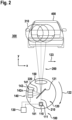
- the Figure 2 shows a schematic representation of the macro lidar system 100 Figure 1 during a scanning process in which an object 400 (in the present case a vehicle) arranged in the observation area 300 of the lidar system 100 is scanned using a laser radiation 200.
- the lidar system 100 has a rotating sensor head 101, which includes a transmitting device 110 with at least one laser source (111) and a receiving device 140 with a detection surface 141.
- the detection surface 141 comprises a line or matrix-shaped subdetector arrangement 143 consisting of a plurality of subdetectors 142 n arranged next to one another in a first extension direction 144.
- a line-shaped subdetector arrangement 143 with only three subdetectors 142n is shown.
- the sensor head 101 further comprises an optical imaging device 150.
- This can, for example, be one or more optical lens elements with the help of which the laser beams 210, 220 are shaped in the desired manner.
- the sensor head 101 can have a beam splitter 121 for superimposing or separating the transmitting and receiving laser beams 210, 220.
- Such an optical beam splitter 121 can be designed, for example, in the form of a partially transparent mirror.
- the lidar system 100 typically also includes a control device 130 for controlling the transmitting and receiving devices 110, 140.
- the control device 130 also includes a measuring device for determining the transit times of the emitted and re-received individual laser pulses and an evaluation device for determining distance information of the sampling points based on the measured transit times.
- the control device 130 or individual components thereof can be arranged outside the sensor head 101 and connected to the respective devices in the sensor head 101 by means of corresponding signal and data lines. Alternatively, you can the control device 130 or individual of its components can be accommodated within the sensor head 101.
- each laser source of the transmitting device 110 generates its own transmitting laser beam 210 in the form of a time sequence of short individual laser pulses.
- the transmitting laser beam 210 illuminates a solid angle defining the detection area 310 of the respective individual laser pulse, which typically represents only a relatively small section of the entire observation area 300 of the lidar system 100. Only through the rotating scanning movement 122 and the associated successive displacement of the detection areas 310 of successive individual laser pulses is a scanning of the entire observation area 300 achieved.
- a measurement sequence with three individual laser pulses emitted one after the other and their respective detection areas 310 is shown. The detection areas 310 are drawn using a dashed line.
- the current detection area 310 of the transmitting laser beam 210 is shown circular in the present exemplary embodiment.
- the cross section of the transmitting laser beam 210 which defines the shape of the detection area 310, can also be designed differently, for example elliptical or approximately square. Due to the scanning movement 122 of the sensor head 101, the individual laser pulses are emitted at different angles, so that the transmitting laser beam 210 with its current detection area 310 travels in predetermined angular steps over the object 400 being scanned.
- the repetition rate of the individual laser pulses and the scanning movement 123 are each coordinated with one another in such a way that an area captured by the transmitting laser beam 210 and thus the scanning points located in the respective area (not shown here) during a scanning pass of several immediately successive individual laser pulses be scanned.
- the transmission laser beam 210 reflected on the object 400 or backscattered by the object 400 is received in the form of a reception laser beam 220 in the sensor head 101 and imaged onto the detection surface 141.
- a scanning point located in the current detection area 310 which can be, for example, a detail of the vehicle 400, is shifted by a defined distance in each case with successive reader pulses Detection area 141 shown.
- the regrouping of subdetectors is described in more detail below, through which a displacement of the macro pixels on the detection area and thus compensation for the rotating scanning movement is achieved.
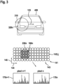
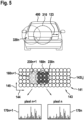
- the show this Figures 3 to 5 which are already in the Figure 2 short scan sequence shown, which includes the scanning of the vehicle 400 using three individual laser pulses.
- the Figure 3 shows a first individual measurement in which the vehicle 400 is illuminated using a first individual laser pulse.
- the current detection area 310 detects at least a first sampling point 320 n , which is imaged on the detection surface 141 in the form of a corresponding image point 230 n .
- the image point 230 n shown by a dashed circle, illuminates a total of nine of the sub-detectors 142 i, j of the matrix-shaped sub-detector arrangement 143, which are in Figure 3 are shown dark hatched.
- the relevant subdetectors 142 i,j are consequently grouped into a first macro-pixel 160 n representing the first sampling point 320 n .
- the signals of the grouped subdetectors 142 i, j are assigned together to a histogram 170 n assigned to the first macro-pixel 160 n . In this histogram 170 n, the signals of all subdetectors 142 i, j assigned to the macro pixel 160 n during the entire measurement are added up. This can improve the signal-to-noise ratio.
- the detection surface 141 has a matrix-shaped subdetector arrangement 143, which comprises a total of fourteen subdetectors 142 i, j arranged next to one another in a first extension direction 144 and a total of five sub-detectors 142 i, j arranged one behind the other in a second extension direction 145.
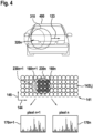
- the transmitting laser beam 210 has moved further in the scanning direction 123 as a result of the scanning movement 122.
- the currently emitted second individual laser pulse therefore has a detection area 310 that is shifted by a certain angular amount in the scanning direction 123.
- the projection of the first scanning point 320 n and thus the position of the first image point 230 n on the detection surface 141 also shifts by a defined amount.
- the displacement of the image point 230 n depends directly on the imaging properties of the optical components as well as the respective angular difference between the individual measurements and thus on the Scan speed 122 and the measurement rate.
- these parameters are coordinated with one another in such a way that the sampling point 320 n is imaged on the detection surface in subsequent individual measurements, shifted by a distance which corresponds as precisely as possible to the lateral width of the subdetectors 142 i,j . In this way it is ensured that the subdetectors 142 i, j can always be uniquely assigned to one of the macro pixels 160 n .
- the steps with which the image points are imaged on the detection surface in a shifted manner during subsequent individual measurements are an integer multiple of the lateral width of the subdetectors 142 i,j .
- the corresponding parameters of the lidar system can also be such that the steps with which the image points are shifted onto the detection surface during subsequent individual measurements are each a fraction of the lateral width of the subdetectors.
- lidar systems can also be implemented in which the displacement of the image points on the detection surface has no rational relationship to the lateral width of the subdetectors 142 i,j . This is possible in particular if immediately adjacent scanning points are imaged on the detection surface at a distance which corresponds at least to the width of a subdetector.
- the displacement of the first pixel 230 n on the detection surface 141 caused by the scanning movement 122 was compensated for by a corresponding displacement of the first macro-pixel 160 n assigned to the first pixel 230 n .
- the first macro-pixel 160 n is shifted by regrouping the relevant subdetectors 142 i,j .
- three new subdetectors 142 i, j have now been assigned to the first macro pixel 160 n on its right side.
- the Figure 5 shows a status of the process during the third individual measurement, which immediately after the in Figure 4 shown second individual measurement follows.
- the transmitting laser beam has moved to the right by a further angular amount, so that the associated detection area 310 is now a further amount compared to that in the Figure 3 shown first individual measurement. Since the relative position of the first sampling point 320 n has changed with respect to the current detection area 310, the first sampling point 320 n is now imaged on the detection surface 141 shifted by a corresponding amount.
- the displacement of the first pixel is 230 n compared to the situation from the Figure 3 now a total of twice the lateral width of the subdetectors 142 i,j . Accordingly, the position of the associated first macro pixel 160 n was changed by regrouping corresponding subdetectors 142 i,j following the position of the first image point 230 n . Compared to the arrangement from Figure 4 three new subdetectors 142 i,j have been assigned to the first macro pixel 160 n on its right side.
- the Figure 6 shows a time diagram that illustrates how the subdetectors 142 i, j of the detection area 141 are individually assigned to different macro pixels 160 n in the course of a scanning process.
- An elliptical light spot 231 is shown, which is generated by the image of the receiving laser beam 220 on the detection surface 141.
- the light spot 231 extends over the entire active part of the detection surface 141, which in the present case only includes five subdetectors 142 i, j for the purpose of illustration.
- the transmitting laser beam 210 is successively guided over successive scanning points as a result of the scanning movement, the corresponding scanning points are imaged one after the other in the form of image points on the detection surface 141.
- the scanning movement creates the impression that the image points and thus the macro pixels assigned to them are moving over the detection surface 141.
- the impression is that the light spot 231, which extends on the detection surface 141 over the above-mentioned group of a total of five subdetectors 142 i, j, moves successively over a row of macro pixels 160 n arranged next to one another.
- This apparent movement of the light spot 231 over a group of three consecutive macro-pixels is shown in the time diagram Figure 6 shown. It can be seen that at time t 6 all subdetectors 142 i, j of the group under consideration are assigned to the middle macro pixel (pixel n).
- a subdetector 142 i,j which is assigned to a first macro-pixel during a first individual laser pulse, is assigned to a second macro-pixel following the first macro-pixel after at least five further individual laser pulses.
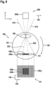
- FIG. 7 A simplified embodiment of the sensor head 101 is shown, wherein the laser beams 235 are imaged directly onto the detection surface 141 by means of an optical imaging device 150 without deflection by a beam splitter.
- the emitted transmitting laser beam with its conical detection area 310 detects an object 400 that is currently in the field of view of the sensor head 101.
- the detected object 400 is scanned at a specific scanning point 320 n .
- the sampling point 320 n is defined by a specific solid angle, which in the present exemplary embodiment is significantly smaller than the solid angle defining the detection area 310.
- the transmitting laser beam is reflected back on the object 400 and received again in the form of a receiving laser beam by the sensor head 101 of the lidar system 100.
- the object becomes 400 assigned sampling point 320 n is imaged in the form of an image point 230 n on the detection surface 141.
- the detection surface 141 which in the present exemplary embodiment is a two-dimensional subdetector arrangement 143 in the form of a 12 ⁇ 8 matrix, is shown in both a side view and a top view.
- a total of 16 subdetectors 142 i,j are detected by the current pixel 230 n , which are in the Figure 7 are drawn dark hatched, grouped into a macro pixel 160 n assigned to the respective pixel. The grouping is done by connecting the subdetectors together, with the signals detected by the individual subdetectors 142 i,j being summed up in a common histogram.
- the Figure 8 shows the arrangement Figure 7 during the subsequent second individual measurement.
- the transmission laser beam 210 has moved further in the scanning direction 123 as a result of the scanning movement 122.
- the detection area 310 of the current individual laser pulse is thus shifted by a certain angular amount in the scanning direction 123. Since the sampling point 320 n is currently located in the center of the detection area 310, the first image point 230 n representing the projection of the first sampling point 320 n is also imaged centrally on the detection area 141.
- the first image point 230 n on the detection surface 141 has a displacement in the first extension direction 144 by a defined distance, which in the present case corresponds to twice the lateral width of the subdetectors.
- the control device of the lidar system 100 In order to compensate for the displacement of the image point 230 n on the detection surface 141 caused by the scanning movement 122 of the sensor head 101, the control device of the lidar system 100 also shifts the position of the macro pixel 160 n assigned to the image point 230 n by activating and deactivating corresponding subdetectors respective route.
- the Figure 9 shows the arrangement from the Figure 7 and 8th in the subsequent third individual measurement. Due to the scanning movement 122 of the sensor head 101, the transmitting laser beam 210 and thus also its detection area 310 have moved further in the scanning direction 123 by the same angular amount as before. The sampling point 320 n is therefore from the perspective of the sensor head 101 shifted further to the left by the corresponding angular amount.
- the first image point 230 n on the detection surface has moved to the right in the first extension direction 144 by twice the lateral width of the subdetectors 142 i,j .
- the associated first macro-pixel 160 n was also shifted to the right by two sub-detectors 142 i, j following the first pixel 230 n by regrouping corresponding sub-detectors 142 i, j .
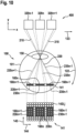
- the Figures 10 and 11 show a further embodiment in which several scanning points arranged laterally next to one another are simultaneously scanned with each individual laser pulse.
- the measuring arrangement essentially corresponds to the arrangement from the Figures 7 to 9 .
- the detection area 310 of the transmitting laser beam 210 comprises a total of three scanning points 320 n-1 , 320 n , 320 n+1 arranged next to one another in the scanning direction 123. Only the middle sampling point 320 n is completely captured, while the two outer sampling points 320 n-1 , 320 n+1 are not completely in the current detection area 310.
- the three sampling points 320 n-1 , 320 n , 320 n+1 are imaged onto different areas of the detection surface 141.
- FIG. 11 shows the arrangement Figure 10 in a subsequent second individual measurement.
- the transmitting laser beam 210 and thus also its current detection area 310 have moved further in the scanning direction 123 by a defined angular amount as a result of the scanning movement 122.
- the three scanning points 320 n-1 , 320 n , 320 n+1 are shifted to the left by the same angular amount against the scanning direction 123, with the left scanning point 320 n-1 almost completely emerging from the detection area 310 is while the right sampling point 320 n+1 has now completely entered the detection area 310.
- the image points 230 n-1 , 230 n , 230 n+1 generated by the projections 235 n-1 , 235 n , 235 n+1 of the scanning points have shifted accordingly by a distance which is twice the lateral width of a subdetector.
- the macro pixels 160 n-1 , 160 n , 160 n+1 assigned to the respective pixels 230 n-1 , 230 n , 230 n+1 were also regrouped by regrouping corresponding subdetectors 142 i,j shifted twice the lateral width of a subdetector.
- a first vertical row of four subdetectors was activated and assigned to the middle macro-pixel 160 n , the sub-detectors of which were previously arranged to the right of the middle macro-pixel 160 n and deactivated were, as well as a second vertical row of four subdetectors, the subdetectors of which were previously assigned to the right macro-pixel 160 n-1 .
- two vertical rows of four subdetectors each were deactivated, the sub-detectors of which were previously assigned to the first macro-pixel 160 n .
- the scanning points in the present exemplary embodiment are at a small distance from one another. This distance enables a sharper separation of the individual sampling points or the associated macro pixels from one another. Depending on the embodiment, this distance can be smaller or larger. If the scanning speed, the measurement rate and the imaging properties of the optical components are coordinated with one another in such a way that the displacement of the scanning points in immediately successive individual measurements corresponds as precisely as possible to the distance between the subdetectors on the detection surface or to an integer multiple of this distance, scanning points can also be used without one such a distance or with only a marginally small distance from each other. This makes it possible to achieve a particularly high lateral image resolution.
- the grouping and activation of the relevant subdetectors is usefully carried out shortly before the reflected or backscattered individual laser pulse hits the detection surface.
- the relevant subdetectors can be grouped into macro pixels if necessary also during or even shortly after the respective individual measurement.
- the basic structure of the invention corresponds to conventional macro lidar scanners.
- conventional scanners have a single one at a time
- the scanner according to the invention uses an arrangement of subdetectors extending in the plane of rotation, for example a subdetector row or a subdetector array (matrix-shaped arrangement of subdetectors).
- the individual subdetectors of the subdetector arrangement can be individually assigned to macro detectors.
- the sequence of a measurement consisting of a number "N" of individual laser pulses was used.
- the in the Figure 3 darkly hatched subdetectors assigned to a first macro pixel 160 n .
- the image of the received single laser pulse is assumed to be centered on the first macro-pixel 160 n .
- the image of the individual laser pulse will move over the two-dimensional subdetector arrangement at a defined speed.
- the first macro-pixel 160 n is shown dark hatched after a shift of exactly one subdetector, while the original position of the first macro-pixel 160 n is indicated by a circle drawn with a dotted line. If the macro-pixel is now divided as indicated, the spatial resolution for the first macro-pixel 160 n is retained, while the pulse energy received by the light-hatched subdetectors and thus also the measurement time is already for the subsequent second macro-pixel 160 n+1 is being used.
- This approach enables multi-pulse measurement principles that, despite the continuous rotational movement, have the same lateral resolution as a single-pulse system. In particular, no pulse energy or measurement time is wasted.
- the principle can basically be used for both biaxial and coaxial macro scanners.
Landscapes
- Engineering & Computer Science (AREA)
- Physics & Mathematics (AREA)
- Computer Networks & Wireless Communication (AREA)
- General Physics & Mathematics (AREA)
- Radar, Positioning & Navigation (AREA)
- Remote Sensing (AREA)
- Electromagnetism (AREA)
- Optical Radar Systems And Details Thereof (AREA)
Applications Claiming Priority (2)
| Application Number | Priority Date | Filing Date | Title |
|---|---|---|---|
| DE102017223102.5A DE102017223102A1 (de) | 2017-12-18 | 2017-12-18 | Multipuls-Lidarsystem zur mehrdimensionalen Erfassung von Objekten |
| PCT/EP2018/085099 WO2019121437A1 (de) | 2017-12-18 | 2018-12-17 | Multipuls-lidarsystem zur mehrdimensionalen erfassung von objekten |
Publications (2)
| Publication Number | Publication Date |
|---|---|
| EP3729137A1 EP3729137A1 (de) | 2020-10-28 |
| EP3729137B1 true EP3729137B1 (de) | 2023-09-20 |
Family
ID=64900880
Family Applications (1)
| Application Number | Title | Priority Date | Filing Date |
|---|---|---|---|
| EP18826568.0A Active EP3729137B1 (de) | 2017-12-18 | 2018-12-17 | Multipuls-lidarsystem zur mehrdimensionalen erfassung von objekten |
Country Status (7)
| Country | Link |
|---|---|
| US (1) | US11940535B2 (zh) |
| EP (1) | EP3729137B1 (zh) |
| JP (1) | JP7114728B2 (zh) |
| KR (1) | KR20200096632A (zh) |
| CN (1) | CN111727381A (zh) |
| DE (1) | DE102017223102A1 (zh) |
| WO (1) | WO2019121437A1 (zh) |
Families Citing this family (19)
| Publication number | Priority date | Publication date | Assignee | Title |
|---|---|---|---|---|
| US10761195B2 (en) | 2016-04-22 | 2020-09-01 | OPSYS Tech Ltd. | Multi-wavelength LIDAR system |
| KR20240007686A (ko) | 2017-03-13 | 2024-01-16 | 옵시스 테크 엘티디 | 눈-안전 스캐닝 lidar 시스템 |
| KR102218679B1 (ko) | 2017-07-28 | 2021-02-23 | 옵시스 테크 엘티디 | 작은 각도 발산을 갖는 vcsel 어레이 lidar 송신기 |
| US11802943B2 (en) | 2017-11-15 | 2023-10-31 | OPSYS Tech Ltd. | Noise adaptive solid-state LIDAR system |
| CN111919137A (zh) | 2018-04-01 | 2020-11-10 | 欧普赛斯技术有限公司 | 噪声自适应固态lidar系统 |
| EP3953727A4 (en) | 2019-04-09 | 2023-01-04 | Opsys Tech Ltd. | SOLID STATE LIDAR TRANSMITTER WITH LASER CONTROL |
| WO2020242834A1 (en) | 2019-05-30 | 2020-12-03 | OPSYS Tech Ltd. | Eye-safe long-range lidar system using actuator |
| DE102019209698A1 (de) * | 2019-07-02 | 2021-01-07 | Ibeo Automotive Systems GmbH | Auslesevorrichtung und Lidar-Messvorrichtung |
| DE102019215751A1 (de) * | 2019-10-14 | 2021-04-15 | Robert Bosch Gmbh | Multipuls-Lidarsystem und Verfahren zur Erfassung eines Objekts in einem Beobachtungsbereich |
| DE102019128439A1 (de) * | 2019-10-22 | 2021-04-22 | Valeo Schalter Und Sensoren Gmbh | Verfahren zum Detektieren von Objekten in einem Überwachungsbereich mit einer optischen Detektionsvorrichtung und optische Detektionsvorrichtung |
| WO2021112763A1 (en) * | 2019-12-05 | 2021-06-10 | Ams Sensors Singapore Pte. Ltd. | Time of flight sensing method |
| US11698447B2 (en) * | 2020-07-17 | 2023-07-11 | Infineon Technologies Ag | Beam steering aware pixel clustering of segmented sensor area and implementing averaging algorithms for pixel processing |
| CN113970757A (zh) * | 2020-07-23 | 2022-01-25 | 华为技术有限公司 | 一种深度成像方法及深度成像系统 |
| KR20220079815A (ko) * | 2020-12-03 | 2022-06-14 | 레이선 인텔리전트 시스템 컴퍼니., 리미티드. | 레이저 레이더 |
| CN117136316A (zh) * | 2021-02-25 | 2023-11-28 | 应诺维思科技有限公司 | 用于生成可变密度点云的lidar系统和方法 |
| WO2022201502A1 (ja) * | 2021-03-26 | 2022-09-29 | パイオニア株式会社 | センサ装置 |
| WO2022201501A1 (ja) * | 2021-03-26 | 2022-09-29 | パイオニア株式会社 | センサ装置 |
| EP4337989A2 (en) * | 2021-05-11 | 2024-03-20 | Opsys Tech Ltd. | Pixel mapping solid-state lidar transmitter system and method |
| CN114594455B (zh) * | 2022-01-13 | 2022-11-18 | 杭州宏景智驾科技有限公司 | 激光雷达系统及其控制方法 |
Family Cites Families (17)
| Publication number | Priority date | Publication date | Assignee | Title |
|---|---|---|---|---|
| WO2002082016A1 (en) | 2001-04-04 | 2002-10-17 | Instro Precision Limited | Surface profile measurement |
| JP2004157044A (ja) * | 2002-11-07 | 2004-06-03 | Nippon Signal Co Ltd:The | 走査型レーザレーダ |
| EP2446301B1 (en) | 2009-06-22 | 2018-08-01 | Toyota Motor Europe | Pulsed light optical rangefinder |
| DE102009029372A1 (de) | 2009-09-11 | 2011-03-24 | Robert Bosch Gmbh | Messvorrichtung zur Messung einer Entfernung zwischen der Messvorrichtung und einem Zielobjekt mit Hilfe optischer Messstrahlung |
| EP2469301A1 (en) * | 2010-12-23 | 2012-06-27 | André Borowski | Methods and devices for generating a representation of a 3D scene at very high speed |
| DE102011005746A1 (de) | 2011-03-18 | 2012-09-20 | Robert Bosch Gmbh | Messvorrichtung zur mehrdimensionalen Vermessung eines Zielobjekts |
| EP2708914A1 (de) | 2012-09-18 | 2014-03-19 | Sick Ag | Optoelektronischer Sensor und Verfahren zur Erfassung einer Tiefenkarte |
| JP6314418B2 (ja) * | 2013-10-18 | 2018-04-25 | 株式会社デンソー | レーダ装置 |
| DE102014207599A1 (de) | 2014-04-23 | 2015-10-29 | Robert Bosch Gmbh | Verfahren und Vorrichtung zum Betreiben eines Fotodetektors |
| DE102014211071A1 (de) | 2014-06-11 | 2015-12-17 | Robert Bosch Gmbh | Fahrzeug-Lidar-System |
| US11125880B2 (en) | 2014-12-09 | 2021-09-21 | Basf Se | Optical detector |
| US10324171B2 (en) * | 2015-12-20 | 2019-06-18 | Apple Inc. | Light detection and ranging sensor |
| CN108603937B (zh) * | 2016-01-31 | 2024-01-05 | 威力登激光雷达有限公司 | 具有远场照射重叠的lidar式3-d成像 |
| DE102016221049A1 (de) | 2016-10-26 | 2018-04-26 | Robert Bosch Gmbh | Vorrichtung und Verfahren zum Empfangen eines reflektierten Lichtpulses in einem Lidar-System |
| US20190369216A1 (en) * | 2017-01-24 | 2019-12-05 | Analog Devices, Inc. | Providing dynamic field of view for light received from a dynamic position |
| CN106970393B (zh) | 2017-03-14 | 2019-12-03 | 南京航空航天大学 | 一种基于码分多址的面阵激光雷达三维成像方法 |
| US10785400B2 (en) * | 2017-10-09 | 2020-09-22 | Stmicroelectronics (Research & Development) Limited | Multiple fields of view time of flight sensor |
-
2017
- 2017-12-18 DE DE102017223102.5A patent/DE102017223102A1/de active Pending
-
2018
- 2018-12-17 EP EP18826568.0A patent/EP3729137B1/de active Active
- 2018-12-17 KR KR1020207020444A patent/KR20200096632A/ko active Search and Examination
- 2018-12-17 WO PCT/EP2018/085099 patent/WO2019121437A1/de unknown
- 2018-12-17 US US16/770,941 patent/US11940535B2/en active Active
- 2018-12-17 CN CN201880089675.4A patent/CN111727381A/zh active Pending
- 2018-12-17 JP JP2020552130A patent/JP7114728B2/ja active Active
Also Published As
| Publication number | Publication date |
|---|---|
| US20210181315A1 (en) | 2021-06-17 |
| EP3729137A1 (de) | 2020-10-28 |
| JP2021507268A (ja) | 2021-02-22 |
| DE102017223102A1 (de) | 2019-06-19 |
| US11940535B2 (en) | 2024-03-26 |
| CN111727381A (zh) | 2020-09-29 |
| KR20200096632A (ko) | 2020-08-12 |
| WO2019121437A1 (de) | 2019-06-27 |
| JP7114728B2 (ja) | 2022-08-08 |
Similar Documents
| Publication | Publication Date | Title |
|---|---|---|
| EP3729137B1 (de) | Multipuls-lidarsystem zur mehrdimensionalen erfassung von objekten | |
| EP3724684B1 (de) | Lidar empfangseinheit | |
| DE19721105C5 (de) | Opto-eletronischer Sensor | |
| EP3374793A1 (de) | Verfahren und vorrichtung zur optischen distanzmessung | |
| EP3633405B1 (de) | Messgerät zur geometrischen 3d-abtastung einer umgebung mit einer vielzahl sendekanäle und semiconductor-photomultiplier sensoren | |
| DE60124647T2 (de) | Vorrichtung und Verfahren zur Abstandsmessung | |
| EP0578129A2 (de) | Bilderfassende Sensoreinheit | |
| DE102013011853A1 (de) | Optoelektronische Detektionseinrichtung und Verfahren zur abtastenden Erfassung der Umgebung eines Kraftfahrzeugs | |
| EP1933167A2 (de) | Optoelektronischer Sensor sowie Verfahren zur Erfassung und Abstandsbestimmung eines Objekts | |
| DE102018214140A1 (de) | LIDAR-Sensor zur optischen Erfassung eines Sichtfeldes, Arbeitsvorrichtung oder Fahrzeug mit einem LIDAR-Sensor und Verfahren zur optischen Erfassung eines Sichtfeldes | |
| EP3832344A1 (de) | Optoelektronischer sensor und verfahren zur erfassung eines objekts | |
| EP3798671B1 (de) | Optoelektronischer sensor und verfahren zur erfassung von objekten | |
| WO2019110206A1 (de) | Lidar-system zur umfelderfassung und verfahren zum betreiben eines lidar-systems | |
| EP3789794A1 (de) | Verfahren und vorrichtung zur distanzmessung | |
| DE102018219476A1 (de) | Vorrichtung für eine optische Abtastung eines Umfeldes der Vorrichtung | |
| DE102009047324A1 (de) | Einrichtung und Verfahren für die Kalibrierung eines optischen Sensors | |
| EP3650888B1 (de) | Optoelektronischer sensor und verfahren zur erfassung und abstandsbestimmung von objekten | |
| WO2021089605A1 (de) | Betriebsverfahren und steuereinheit für ein lidar-system, lidar-system und vorrichtung | |
| EP3329300B1 (de) | Optische sensorvorrichtung für ein kraftfahrzeug zum zweidimensionalen abtasten eines umgebungsbereiches des kraftfahrzeugs, kraftfahrzeug sowie verfahren | |
| EP1612583B1 (de) | Vorrichtung und Verfahren zum Auslesen von in einer Speicherphosphorschicht gespeicherten Röntgeninformationen | |
| DE102019133135A1 (de) | Lidar-sensor | |
| WO2021073824A1 (de) | Multipuls-lidarsystem und verfahren zur erfassung eines objekts in einem beobachtungsbereich | |
| EP3126866B1 (de) | Erfassungseinrichtung, insbesondere zur nutzung in einem kraftfahrzeug und kraftfahrzeug | |
| DE102019106411B4 (de) | Laserscaneinrichtung und Verfahren zur dreidimensionalen Vermessung einer Szenerie in großer Entfernung | |
| DE102018107363B4 (de) | Verfahren und Sensor zum Erzeugen von 3D-Bilddaten |
Legal Events
| Date | Code | Title | Description |
|---|---|---|---|
| STAA | Information on the status of an ep patent application or granted ep patent |
Free format text: STATUS: UNKNOWN |
|
| STAA | Information on the status of an ep patent application or granted ep patent |
Free format text: STATUS: THE INTERNATIONAL PUBLICATION HAS BEEN MADE |
|
| PUAI | Public reference made under article 153(3) epc to a published international application that has entered the european phase |
Free format text: ORIGINAL CODE: 0009012 |
|
| STAA | Information on the status of an ep patent application or granted ep patent |
Free format text: STATUS: REQUEST FOR EXAMINATION WAS MADE |
|
| 17P | Request for examination filed |
Effective date: 20200720 |
|
| AK | Designated contracting states |
Kind code of ref document: A1 Designated state(s): AL AT BE BG CH CY CZ DE DK EE ES FI FR GB GR HR HU IE IS IT LI LT LU LV MC MK MT NL NO PL PT RO RS SE SI SK SM TR |
|
| AX | Request for extension of the european patent |
Extension state: BA ME |
|
| DAV | Request for validation of the european patent (deleted) | ||
| DAX | Request for extension of the european patent (deleted) | ||
| STAA | Information on the status of an ep patent application or granted ep patent |
Free format text: STATUS: EXAMINATION IS IN PROGRESS |
|
| 17Q | First examination report despatched |
Effective date: 20211126 |
|
| GRAP | Despatch of communication of intention to grant a patent |
Free format text: ORIGINAL CODE: EPIDOSNIGR1 |
|
| STAA | Information on the status of an ep patent application or granted ep patent |
Free format text: STATUS: GRANT OF PATENT IS INTENDED |
|
| RIC1 | Information provided on ipc code assigned before grant |
Ipc: G01S 7/481 20060101ALI20230419BHEP Ipc: G01S 7/4865 20200101ALI20230419BHEP Ipc: G01S 7/4863 20200101ALI20230419BHEP Ipc: G01S 17/42 20060101ALI20230419BHEP Ipc: G01S 17/10 20200101ALI20230419BHEP Ipc: G01S 17/931 20200101ALI20230419BHEP Ipc: G01S 17/89 20200101AFI20230419BHEP |
|
| INTG | Intention to grant announced |
Effective date: 20230524 |
|
| GRAS | Grant fee paid |
Free format text: ORIGINAL CODE: EPIDOSNIGR3 |
|
| GRAA | (expected) grant |
Free format text: ORIGINAL CODE: 0009210 |
|
| STAA | Information on the status of an ep patent application or granted ep patent |
Free format text: STATUS: THE PATENT HAS BEEN GRANTED |
|
| AK | Designated contracting states |
Kind code of ref document: B1 Designated state(s): AL AT BE BG CH CY CZ DE DK EE ES FI FR GB GR HR HU IE IS IT LI LT LU LV MC MK MT NL NO PL PT RO RS SE SI SK SM TR |
|
| REG | Reference to a national code |
Ref country code: GB Ref legal event code: FG4D Free format text: NOT ENGLISH |
|
| REG | Reference to a national code |
Ref country code: CH Ref legal event code: EP |
|
| REG | Reference to a national code |
Ref country code: DE Ref legal event code: R096 Ref document number: 502018013293 Country of ref document: DE |
|
| REG | Reference to a national code |
Ref country code: IE Ref legal event code: FG4D Free format text: LANGUAGE OF EP DOCUMENT: GERMAN |
|
| REG | Reference to a national code |
Ref country code: LT Ref legal event code: MG9D |
|
| PG25 | Lapsed in a contracting state [announced via postgrant information from national office to epo] |
Ref country code: GR Free format text: LAPSE BECAUSE OF FAILURE TO SUBMIT A TRANSLATION OF THE DESCRIPTION OR TO PAY THE FEE WITHIN THE PRESCRIBED TIME-LIMIT Effective date: 20231221 |
|
| PGFP | Annual fee paid to national office [announced via postgrant information from national office to epo] |
Ref country code: GB Payment date: 20231220 Year of fee payment: 6 |
|
| REG | Reference to a national code |
Ref country code: NL Ref legal event code: MP Effective date: 20230920 |
|
| PG25 | Lapsed in a contracting state [announced via postgrant information from national office to epo] |
Ref country code: SE Free format text: LAPSE BECAUSE OF FAILURE TO SUBMIT A TRANSLATION OF THE DESCRIPTION OR TO PAY THE FEE WITHIN THE PRESCRIBED TIME-LIMIT Effective date: 20230920 Ref country code: RS Free format text: LAPSE BECAUSE OF FAILURE TO SUBMIT A TRANSLATION OF THE DESCRIPTION OR TO PAY THE FEE WITHIN THE PRESCRIBED TIME-LIMIT Effective date: 20230920 Ref country code: NO Free format text: LAPSE BECAUSE OF FAILURE TO SUBMIT A TRANSLATION OF THE DESCRIPTION OR TO PAY THE FEE WITHIN THE PRESCRIBED TIME-LIMIT Effective date: 20231220 Ref country code: LV Free format text: LAPSE BECAUSE OF FAILURE TO SUBMIT A TRANSLATION OF THE DESCRIPTION OR TO PAY THE FEE WITHIN THE PRESCRIBED TIME-LIMIT Effective date: 20230920 Ref country code: LT Free format text: LAPSE BECAUSE OF FAILURE TO SUBMIT A TRANSLATION OF THE DESCRIPTION OR TO PAY THE FEE WITHIN THE PRESCRIBED TIME-LIMIT Effective date: 20230920 Ref country code: HR Free format text: LAPSE BECAUSE OF FAILURE TO SUBMIT A TRANSLATION OF THE DESCRIPTION OR TO PAY THE FEE WITHIN THE PRESCRIBED TIME-LIMIT Effective date: 20230920 Ref country code: GR Free format text: LAPSE BECAUSE OF FAILURE TO SUBMIT A TRANSLATION OF THE DESCRIPTION OR TO PAY THE FEE WITHIN THE PRESCRIBED TIME-LIMIT Effective date: 20231221 Ref country code: FI Free format text: LAPSE BECAUSE OF FAILURE TO SUBMIT A TRANSLATION OF THE DESCRIPTION OR TO PAY THE FEE WITHIN THE PRESCRIBED TIME-LIMIT Effective date: 20230920 |
|
| PGFP | Annual fee paid to national office [announced via postgrant information from national office to epo] |
Ref country code: FR Payment date: 20231219 Year of fee payment: 6 |
|
| PG25 | Lapsed in a contracting state [announced via postgrant information from national office to epo] |
Ref country code: NL Free format text: LAPSE BECAUSE OF FAILURE TO SUBMIT A TRANSLATION OF THE DESCRIPTION OR TO PAY THE FEE WITHIN THE PRESCRIBED TIME-LIMIT Effective date: 20230920 |
|
| PG25 | Lapsed in a contracting state [announced via postgrant information from national office to epo] |
Ref country code: IS Free format text: LAPSE BECAUSE OF FAILURE TO SUBMIT A TRANSLATION OF THE DESCRIPTION OR TO PAY THE FEE WITHIN THE PRESCRIBED TIME-LIMIT Effective date: 20240120 |
|
| PG25 | Lapsed in a contracting state [announced via postgrant information from national office to epo] |
Ref country code: ES Free format text: LAPSE BECAUSE OF FAILURE TO SUBMIT A TRANSLATION OF THE DESCRIPTION OR TO PAY THE FEE WITHIN THE PRESCRIBED TIME-LIMIT Effective date: 20230920 |
|
| PG25 | Lapsed in a contracting state [announced via postgrant information from national office to epo] |
Ref country code: SM Free format text: LAPSE BECAUSE OF FAILURE TO SUBMIT A TRANSLATION OF THE DESCRIPTION OR TO PAY THE FEE WITHIN THE PRESCRIBED TIME-LIMIT Effective date: 20230920 Ref country code: RO Free format text: LAPSE BECAUSE OF FAILURE TO SUBMIT A TRANSLATION OF THE DESCRIPTION OR TO PAY THE FEE WITHIN THE PRESCRIBED TIME-LIMIT Effective date: 20230920 Ref country code: IS Free format text: LAPSE BECAUSE OF FAILURE TO SUBMIT A TRANSLATION OF THE DESCRIPTION OR TO PAY THE FEE WITHIN THE PRESCRIBED TIME-LIMIT Effective date: 20240120 Ref country code: ES Free format text: LAPSE BECAUSE OF FAILURE TO SUBMIT A TRANSLATION OF THE DESCRIPTION OR TO PAY THE FEE WITHIN THE PRESCRIBED TIME-LIMIT Effective date: 20230920 Ref country code: EE Free format text: LAPSE BECAUSE OF FAILURE TO SUBMIT A TRANSLATION OF THE DESCRIPTION OR TO PAY THE FEE WITHIN THE PRESCRIBED TIME-LIMIT Effective date: 20230920 Ref country code: CZ Free format text: LAPSE BECAUSE OF FAILURE TO SUBMIT A TRANSLATION OF THE DESCRIPTION OR TO PAY THE FEE WITHIN THE PRESCRIBED TIME-LIMIT Effective date: 20230920 Ref country code: SK Free format text: LAPSE BECAUSE OF FAILURE TO SUBMIT A TRANSLATION OF THE DESCRIPTION OR TO PAY THE FEE WITHIN THE PRESCRIBED TIME-LIMIT Effective date: 20230920 Ref country code: PT Free format text: LAPSE BECAUSE OF FAILURE TO SUBMIT A TRANSLATION OF THE DESCRIPTION OR TO PAY THE FEE WITHIN THE PRESCRIBED TIME-LIMIT Effective date: 20240122 |
|
| PGFP | Annual fee paid to national office [announced via postgrant information from national office to epo] |
Ref country code: DE Payment date: 20240227 Year of fee payment: 6 |