EP3728925B1 - Dual containment fitting assembly - Google Patents
Dual containment fitting assembly Download PDFInfo
- Publication number
- EP3728925B1 EP3728925B1 EP18891753.8A EP18891753A EP3728925B1 EP 3728925 B1 EP3728925 B1 EP 3728925B1 EP 18891753 A EP18891753 A EP 18891753A EP 3728925 B1 EP3728925 B1 EP 3728925B1
- Authority
- EP
- European Patent Office
- Prior art keywords
- containment
- primary
- tubing
- dual
- wall
- Prior art date
- Legal status (The legal status is an assumption and is not a legal conclusion. Google has not performed a legal analysis and makes no representation as to the accuracy of the status listed.)
- Active
Links
Images


Classifications
-
- F—MECHANICAL ENGINEERING; LIGHTING; HEATING; WEAPONS; BLASTING
- F16—ENGINEERING ELEMENTS AND UNITS; GENERAL MEASURES FOR PRODUCING AND MAINTAINING EFFECTIVE FUNCTIONING OF MACHINES OR INSTALLATIONS; THERMAL INSULATION IN GENERAL
- F16L—PIPES; JOINTS OR FITTINGS FOR PIPES; SUPPORTS FOR PIPES, CABLES OR PROTECTIVE TUBING; MEANS FOR THERMAL INSULATION IN GENERAL
- F16L17/00—Joints with packing adapted to sealing by fluid pressure
-
- F—MECHANICAL ENGINEERING; LIGHTING; HEATING; WEAPONS; BLASTING
- F16—ENGINEERING ELEMENTS AND UNITS; GENERAL MEASURES FOR PRODUCING AND MAINTAINING EFFECTIVE FUNCTIONING OF MACHINES OR INSTALLATIONS; THERMAL INSULATION IN GENERAL
- F16L—PIPES; JOINTS OR FITTINGS FOR PIPES; SUPPORTS FOR PIPES, CABLES OR PROTECTIVE TUBING; MEANS FOR THERMAL INSULATION IN GENERAL
- F16L19/00—Joints in which sealing surfaces are pressed together by means of a member, e.g. a swivel nut, screwed on, or into, one of the joint parts
- F16L19/02—Pipe ends provided with collars or flanges, integral with the pipe or not, pressed together by a screwed member
-
- F—MECHANICAL ENGINEERING; LIGHTING; HEATING; WEAPONS; BLASTING
- F16—ENGINEERING ELEMENTS AND UNITS; GENERAL MEASURES FOR PRODUCING AND MAINTAINING EFFECTIVE FUNCTIONING OF MACHINES OR INSTALLATIONS; THERMAL INSULATION IN GENERAL
- F16L—PIPES; JOINTS OR FITTINGS FOR PIPES; SUPPORTS FOR PIPES, CABLES OR PROTECTIVE TUBING; MEANS FOR THERMAL INSULATION IN GENERAL
- F16L19/00—Joints in which sealing surfaces are pressed together by means of a member, e.g. a swivel nut, screwed on, or into, one of the joint parts
- F16L19/02—Pipe ends provided with collars or flanges, integral with the pipe or not, pressed together by a screwed member
- F16L19/0206—Pipe ends provided with collars or flanges, integral with the pipe or not, pressed together by a screwed member the collar not being integral with the pipe
-
- F—MECHANICAL ENGINEERING; LIGHTING; HEATING; WEAPONS; BLASTING
- F16—ENGINEERING ELEMENTS AND UNITS; GENERAL MEASURES FOR PRODUCING AND MAINTAINING EFFECTIVE FUNCTIONING OF MACHINES OR INSTALLATIONS; THERMAL INSULATION IN GENERAL
- F16L—PIPES; JOINTS OR FITTINGS FOR PIPES; SUPPORTS FOR PIPES, CABLES OR PROTECTIVE TUBING; MEANS FOR THERMAL INSULATION IN GENERAL
- F16L19/00—Joints in which sealing surfaces are pressed together by means of a member, e.g. a swivel nut, screwed on, or into, one of the joint parts
- F16L19/02—Pipe ends provided with collars or flanges, integral with the pipe or not, pressed together by a screwed member
- F16L19/0237—Pipe ends provided with collars or flanges, integral with the pipe or not, pressed together by a screwed member specially adapted for use with attachments, e.g. reduction units, T-pieces, bends or the like
-
- F—MECHANICAL ENGINEERING; LIGHTING; HEATING; WEAPONS; BLASTING
- F16—ENGINEERING ELEMENTS AND UNITS; GENERAL MEASURES FOR PRODUCING AND MAINTAINING EFFECTIVE FUNCTIONING OF MACHINES OR INSTALLATIONS; THERMAL INSULATION IN GENERAL
- F16L—PIPES; JOINTS OR FITTINGS FOR PIPES; SUPPORTS FOR PIPES, CABLES OR PROTECTIVE TUBING; MEANS FOR THERMAL INSULATION IN GENERAL
- F16L19/00—Joints in which sealing surfaces are pressed together by means of a member, e.g. a swivel nut, screwed on, or into, one of the joint parts
- F16L19/02—Pipe ends provided with collars or flanges, integral with the pipe or not, pressed together by a screwed member
- F16L19/025—Pipe ends provided with collars or flanges, integral with the pipe or not, pressed together by a screwed member the pipe ends having integral collars or flanges
- F16L19/028—Pipe ends provided with collars or flanges, integral with the pipe or not, pressed together by a screwed member the pipe ends having integral collars or flanges the collars or flanges being obtained by deformation of the pipe wall
- F16L19/0283—Pipe ends provided with collars or flanges, integral with the pipe or not, pressed together by a screwed member the pipe ends having integral collars or flanges the collars or flanges being obtained by deformation of the pipe wall and having a bell-mouthed shape
-
- F—MECHANICAL ENGINEERING; LIGHTING; HEATING; WEAPONS; BLASTING
- F16—ENGINEERING ELEMENTS AND UNITS; GENERAL MEASURES FOR PRODUCING AND MAINTAINING EFFECTIVE FUNCTIONING OF MACHINES OR INSTALLATIONS; THERMAL INSULATION IN GENERAL
- F16L—PIPES; JOINTS OR FITTINGS FOR PIPES; SUPPORTS FOR PIPES, CABLES OR PROTECTIVE TUBING; MEANS FOR THERMAL INSULATION IN GENERAL
- F16L27/00—Adjustable joints; Joints allowing movement
-
- F—MECHANICAL ENGINEERING; LIGHTING; HEATING; WEAPONS; BLASTING
- F16—ENGINEERING ELEMENTS AND UNITS; GENERAL MEASURES FOR PRODUCING AND MAINTAINING EFFECTIVE FUNCTIONING OF MACHINES OR INSTALLATIONS; THERMAL INSULATION IN GENERAL
- F16L—PIPES; JOINTS OR FITTINGS FOR PIPES; SUPPORTS FOR PIPES, CABLES OR PROTECTIVE TUBING; MEANS FOR THERMAL INSULATION IN GENERAL
- F16L33/00—Arrangements for connecting hoses to rigid members; Rigid hose-connectors, i.e. single members engaging both hoses
- F16L33/24—Arrangements for connecting hoses to rigid members; Rigid hose-connectors, i.e. single members engaging both hoses with parts screwed directly on or into the hose
-
- F—MECHANICAL ENGINEERING; LIGHTING; HEATING; WEAPONS; BLASTING
- F16—ENGINEERING ELEMENTS AND UNITS; GENERAL MEASURES FOR PRODUCING AND MAINTAINING EFFECTIVE FUNCTIONING OF MACHINES OR INSTALLATIONS; THERMAL INSULATION IN GENERAL
- F16L—PIPES; JOINTS OR FITTINGS FOR PIPES; SUPPORTS FOR PIPES, CABLES OR PROTECTIVE TUBING; MEANS FOR THERMAL INSULATION IN GENERAL
- F16L39/00—Joints or fittings for double-walled or multi-channel pipes or pipe assemblies
- F16L39/005—Joints or fittings for double-walled or multi-channel pipes or pipe assemblies for concentric pipes
-
- F—MECHANICAL ENGINEERING; LIGHTING; HEATING; WEAPONS; BLASTING
- F16—ENGINEERING ELEMENTS AND UNITS; GENERAL MEASURES FOR PRODUCING AND MAINTAINING EFFECTIVE FUNCTIONING OF MACHINES OR INSTALLATIONS; THERMAL INSULATION IN GENERAL
- F16L—PIPES; JOINTS OR FITTINGS FOR PIPES; SUPPORTS FOR PIPES, CABLES OR PROTECTIVE TUBING; MEANS FOR THERMAL INSULATION IN GENERAL
- F16L47/00—Connecting arrangements or other fittings specially adapted to be made of plastics or to be used with pipes made of plastics
- F16L47/04—Connecting arrangements or other fittings specially adapted to be made of plastics or to be used with pipes made of plastics with a swivel nut or collar engaging the pipe
- F16L47/041—Connecting arrangements or other fittings specially adapted to be made of plastics or to be used with pipes made of plastics with a swivel nut or collar engaging the pipe the plastic pipe end being flared either before or during the making of the connection
-
- F—MECHANICAL ENGINEERING; LIGHTING; HEATING; WEAPONS; BLASTING
- F16—ENGINEERING ELEMENTS AND UNITS; GENERAL MEASURES FOR PRODUCING AND MAINTAINING EFFECTIVE FUNCTIONING OF MACHINES OR INSTALLATIONS; THERMAL INSULATION IN GENERAL
- F16L—PIPES; JOINTS OR FITTINGS FOR PIPES; SUPPORTS FOR PIPES, CABLES OR PROTECTIVE TUBING; MEANS FOR THERMAL INSULATION IN GENERAL
- F16L11/00—Hoses, i.e. flexible pipes
- F16L11/04—Hoses, i.e. flexible pipes made of rubber or flexible plastics
-
- F—MECHANICAL ENGINEERING; LIGHTING; HEATING; WEAPONS; BLASTING
- F16—ENGINEERING ELEMENTS AND UNITS; GENERAL MEASURES FOR PRODUCING AND MAINTAINING EFFECTIVE FUNCTIONING OF MACHINES OR INSTALLATIONS; THERMAL INSULATION IN GENERAL
- F16L—PIPES; JOINTS OR FITTINGS FOR PIPES; SUPPORTS FOR PIPES, CABLES OR PROTECTIVE TUBING; MEANS FOR THERMAL INSULATION IN GENERAL
- F16L19/00—Joints in which sealing surfaces are pressed together by means of a member, e.g. a swivel nut, screwed on, or into, one of the joint parts
- F16L19/02—Pipe ends provided with collars or flanges, integral with the pipe or not, pressed together by a screwed member
- F16L19/0212—Pipe ends provided with collars or flanges, integral with the pipe or not, pressed together by a screwed member using specially adapted sealing means
-
- F—MECHANICAL ENGINEERING; LIGHTING; HEATING; WEAPONS; BLASTING
- F16—ENGINEERING ELEMENTS AND UNITS; GENERAL MEASURES FOR PRODUCING AND MAINTAINING EFFECTIVE FUNCTIONING OF MACHINES OR INSTALLATIONS; THERMAL INSULATION IN GENERAL
- F16L—PIPES; JOINTS OR FITTINGS FOR PIPES; SUPPORTS FOR PIPES, CABLES OR PROTECTIVE TUBING; MEANS FOR THERMAL INSULATION IN GENERAL
- F16L49/00—Connecting arrangements, e.g. joints, specially adapted for pipes of brittle material, e.g. glass, earthenware
- F16L49/06—Joints in which sealing surfaces are pressed together by means of a member, e.g. swivel nut, screwed on, or into, one of the joint parts
Definitions
- the present disclosure relates generally to a dual containment fitting. More particularly, the present disclosure related to a dual containment fitting for connecting tubing to a secondary fluid transfer component in a dual containment fitting assembly.
- Dual containment fitting assemblies are designed to connect threaded and non-threaded tubing to secondary components, such as other tubing or valve assemblies.
- the use of such assemblies can facilitate connections of concentric inner and outer plastic tubes in an arrangement such that the outer tubing contains any leakage of fluid from the inner tubing.
- Such dual fitting assemblies reduces the problem of leakage from the inner tubing itself, in view of the aggressive nature of the caustic chemicals and process conditions that are used in the semiconductor manufacturing industry, it is desirable that additional containment options be developed for possible leakage around the connection between the tubing and the secondary components. It is therefore desirable that improved fitting assemblies continue to be developed in order to provide additional leakage protection around the intersections between the tubing and the secondary components.
- US 2006/0157975 A1 describes a double-pipe joint.
- an inner joint portion for coupling the inner pipe is formed by: a sleeve which is to be pressingly fitted into an inner-pipe end portion; an inner-pipe joint body which is to be fitted onto the end portion; and an inner-pipe union nut.
- An outer joint portion for coupling the outer pipe is formed by: a sleeve which is to be pressingly fitted into an outer-pipe end portion; an outer-pipe joint body which is to be fitted onto the end portion; and an 25 outer-pipe union nut.
- the inner-pipe union nut and the outer-pipe joint body are formed integrally into a nut-equipped body.
- US 2 181 002 A relates to elastic fluid turbine plants, more particularly to arrangements for supplying oil or like Inflammable substance under pressure to hydraulic motors, bearings or other elements forming part of or associated with elastic fluid turbines.
- the invention in a first aspect comprises a dual containment fitting assembly as defined in claim 1. Further aspects are defined in the dependent claims.
- Embodiments described herein are generally directed to a dual containment fitting for connecting tubing or a tubing type component to a valve assembly or to another tubing type component.
- the dual containment fitting is configured such that the connection includes leak containment spaces surrounding a primary tubing and the intersection between the tubing component and the valve assembly or the additional tubing component.
- the dual containment fitting that may include a primary tubing, a secondary tubing, and a dual containment body.
- the combination of the dual containment fitting connected to the valve assemble or the additional tubing component may be referred to as a dual containment fitting assembly.
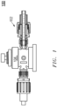
- FIG. 1 includes an illustration of a perspective view of a dual containment fitting assembly 100 that may include a dual containment fitting 102 connected to a valve assembly 104.
- FIG. 2 includes an illustration of the dual containment fitting 102 connected to a valve assembly 104.
- the dual containment fitting 102 may include a primary tubing 110, a secondary tubing 120, and a dual containment body 130.
- the primary tubing 110 may include a flared end 112, a first portion 114 and a second portion 116.
- the secondary tubing 120 may include a flared end 122.
- the secondary tubing 120 may surround the first portion 114 of the primary tubing 110. According to still other embodiments, the secondary tubing 120 may be concentric with the first portion 114 of the primary tubing 110. According to yet other embodiments, the secondary tubing 120 may form a first leak containment space 140 between the first portion 114 of the primary tubing 110 and the secondary tubing 120.
- the dual containment body 130 may include a flare fitting portion 132, a primary containment nut portion 134 and a bore therethrough.
- the flare fitting portion 132 may surround the second portion 116 of the primary tubing 110. According to yet other embodiments, the flare fitting portion 132 may be concentric with the second portion 116 of the primary tubing 110. According to yet other embodiment, the flare fitting portion 132 second leak containment space 142 between the second portion 116 of the primary tubing 110 and the flare fitting portion 132 of the dual containment body 130. According to still other embodiments, the flare fitting portion 132 of the dual containment body 130 may compressively engage with the flared end 112 of the secondary tubing 120 connecting the first leak containment space 140 with the second leak containment space 142.
- the primary containment nut portion 134 may surround the flared end 112 of the primary tubing 110. According to still other embodiments, the primary containment nut portion 134 may be concentric with the flared end 112 of the primary tubing 110. According to still other embodiments, the primary containment nut portion 134 may form a third leak containment space 144 between the flared end 112 of the primary tubing 110 and the primary containment nut portion 134 of the dual containment body 130.
- the primary containment nut portion 134 may include at least one leak passage hole 135 connecting the third leak containment space 144 with the second leak containment space 142.
- the deal containment fitting 102 may further include a secondary containment nut 150.
- the secondary containment nut 150 may surround the flared end 122 of the secondary tubing 120.
- the secondary containment nut 150 may be concentric with the flared end 122 of the secondary tubing 120.
- the secondary containment nut 150 may threadably engage with the flare fitting portion 132 of the dual containment body 130.
- the secondary containment nut 150 may compressively engage the flared end 122 of the secondary tubing 120 with the flare fitting portion 132 of the dual containment body130.
- FIG. 3 includes an illustration of an alternative view of the primary containment nut portion 134 of the dual containment body 130 of the dual containment fitting 102 illustrated in FIG. 2 .
- FIG. 3 further illustrates the leak passage hoes 135 through the primary containment nut portion 134.
- FIG. 4 includes an illustration of an alternative view of the primary containment nut portion 134 of the dual containment body 130 of the dual containment fitting 102 illustrated in FIG. 2 .
- FIG. 4 further illustrates the leak passage hoes 135 through the primary containment nut portion 134.
- FIG. 5 includes an illustration of an alternative view of the primary containment nut portion 134 of the dual containment body 130 of the dual containment fitting 102 illustrated in FIG. 2 .
- FIG. 3 further illustrates the leak passage hoes 135 through the primary containment nut portion 134.
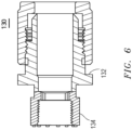
- FIG. 6 includes an illustration of dual containment body 130.
- the dual containment body 130 may include a flare fitting portion 132, a primary containment nut portion 134 and a bore therethrough as illustrated in FIG. 2 .
- the primary tubing 110 may include a particular material. According to still other embodiments, the primary tubing 110 may include a polymer material. According to yet other embodiments, the primary tubing 110 may consist essentially of a polymer material. According to other embodiments, the polymer material of the primary tubing 110 may include perfluoroalkoxy (PFA). According to yet other embodiments, the polymer material of the primary tubing 110 may consist essentially of perfluoroalkoxy (PFA). According to still other embodiments, the primary tubing 110 may include perfluoroalkoxy (PFA). According to yet other embodiments, the primary tubing 110 may consist essentially of perfluoroalkoxy (PFA).
- the primary tubing 110 may include an outer wall.
- the outer wall of the primary tubing 110 may have a particular thickness.
- the outer wall of the primary tubing 110 may have a thickness of at least about 1 mm, such as, at least about 1.05 mm or at least about 1.1 mm or at least about 1.15 mm or at least about 1.2 mm or at least about 1.25 mm or at least about 1.3 mm or at least about 1.35 mm or at least about 1.4 mm or at least about 1.45 mm or even at least about 1.5 mm.
- the outer wall of the primary tubing 110 may have a thickness of not greater than about 2.0 mm, such as, not greater than about 1.95 mm or not greater than about 1.9 mm or not greater than about 1.85 mm or not greater than about 1.8 mm or not greater than about 1.75 mm or not greater than about 1.7 mm or not greater than about 1.65 mm or even not greater than about 1.6 mm. It will be appreciated that the thickness of the outer wall of the primary tubing 110 may be within a range between any of the values noted above. It will be further appreciated that the thickness of the outer wall of the primary tubing 110 may be any value between any of the values noted above.
- the primary tubing 110 may have a particular average inner diameter.
- the average inner diameter of the primary tubing 110 may be at least about 3.0 mm, such as, at least about 3.25 mm or at least about 3.5 mm or at least about 3.75 mm or at least about 4.0 mm or at least about 4.25 mm or at least about 4.50 mm or at least about 4.75 mm or at least about 5.0 mm or at least about 5.25 mm or at least about 5.5 mm or at least about 5.75 mm or at least about 6.0 mm or at least about 6.25 mm or at least about 6.5 mm or at least about 6.75 mm or at least about 7.0 mm or at least about 7.25 mm or at least about 7.5 mm or at least about 7.75 mm or at least about 8.0 mm or at least about 8.25 mm or at least about 8.5 mm or at least about 8.75 mm or at least about 9.0 mm or at least about 9.25 mm or at least about 9.5 mm or
- the average inner diameter of the primary tubing 110 may be not greater than about 20 mm, such as, not greater than about 19.75 mm or not greater than about 19.5 mm or not greater than about 19.25 mm or not greater than about 19.0 mm or not greater than about 18.75 mm or not greater than about 18.5 mm or not greater than about 18.25 mm or not greater than about 18.0 mm or not greater than about 17.75 mm or not greater than about 17.5 mm or not greater than about 17.25 mm or not greater than about 17.0 mm or not greater than about 16.75 mm or not greater than about 16.5 mm or not greater than about 16.0 mm or not greater than about 15.75 mm or not greater than about 15.5 mm or not greater than about 15.25 mm or not greater than about 15.0 mm or not greater than about 14.75 mm or not greater than about 14.5 mm or not greater than about 14.25 mm or not greater than about 14.0 mm.
- the average inner diameter of the outer wall of the primary tubing 110 may be within a range between any of the values noted above. It will be further appreciated that the inner diameter of the outer wall of the primary tubing 110 may be any value between any of the values noted above.
- the primary tubing 110 may have a particular average outer diameter.
- the average outer diameter of the primary tubing 110 may be at least about 5 mm, such as, at least about 5.5 mm or at least about 6.0 mm or at least about 6.5 mm or at least about 7.0 mm or at least about 7.5 mm or at least about 8.0 mm or at least about 8.5 mm or at least about 9.0 mm or at least about 9.5 mm or at least about 10.0 mm or at least about 10.5 mm or at least about 11 mm or at least about 11.5 mm or at least about 12.0 mm or even at least about 12.5 mm.
- the average outer diameter of the primary tubing 110 may be not greater than about 20 mm, such as, not greater than about 19.5 mm or not greater than about 19.0 mm or not greater than about 18 mm or not greater than about 18.5 mm or not greater than about 18 mm or not greater than about 17.5 mm or not greater than about 17.0 mm or not greater than about 16.5 mm or not greater than about 16.0 mm or not greater than about 15.5 mm or not greater than about 15.0 mm or not greater than about 14.5 mm or not greater than about 14.0 mm or not greater than about 13.5 mm or even not greater than about 13 mm.
- the average outer diameter of the outer wall of the primary tubing 110 may be within a range between any of the values noted above. It will be further appreciated that the outer diameter of the outer wall of the primary tubing 110 may be any value between any of the values noted above.
- the flared end 112 of the primary tubing 110 may include a particular material. According to still other embodiments, the flared end 112 of the primary tubing 110 may include a polymer material. According to yet other embodiments, the flared end 112 of the primary tubing 110 may consist essentially of a polymer material. According to other embodiments, the polymer material of the flared end 112 of the primary tubing 110 may include perfluoroalkoxy (PFA). According to yet other embodiments, the polymer material of the flared end 112 of the primary tubing 110 may consist essentially of perfluoroalkoxy (PFA). According to still other embodiments, the flared end 112 of the primary tubing 110 may include perfluoroalkoxy (PFA). According to yet other embodiments, the flared end 112 of the primary tubing 110 may consist essentially of perfluoroalkoxy (PFA).
- the flared end 112 of the primary tubing 110 may include an outer wall.
- the outer wall of the flared end 112 of the primary tubing 110 may have a particular thickness.
- the outer wall of the flared end 112 of the primary tubing 110 may have a thickness of at least about 1 mm, such as, at least about 1.05 mm or at least about 1.1 mm or at least about 1.15 mm or at least about 1.2 mm or at least about 1.25 mm or at least about 1.3 mm or at least about 1.35 mm or at least about 1.4 mm or at least about 1.45 mm or even at least about 1.5 mm.
- the outer wall of the flared end 112 of the primary tubing 110 may have a thickness of not greater than about 2.0 mm, such as, not greater than about 1.95 mm or not greater than about 1.9 mm or not greater than about 1.85 mm or not greater than about 1.8 mm or not greater than about 1.75 mm or not greater than about 1.7 mm or not greater than about 1.65 mm or even not greater than about 1.6 mm. It will be appreciated that the thickness of the outer wall of the flared end 112 of the primary tubing 110 may be within a range between any of the values noted above. It will be further appreciated that the thickness of the outer wall of the flared end 112 of the primary tubing 110 may be any value between any of the values noted above.
- the flared end 112 of the primary tubing 110 may have a particular maximum inner diameter.
- the maximum inner diameter of the flared end 112 of the primary tubing 110 may be at least about 5.0 mm, such as, at least about 5.5 mm or at least about 6.0 mm or at least about 6.5 mm or at least about 7.0 mm or at least about 7.5 mm or at least about 8.0 mm or at least about 8.5 mm or at least about 9.0 mm or at least about 9.5 mm or at least about 10.0 mm or at least about 10.5 mm or at least about 11.0 mm or at least about 11.5 mm or at least about 12.0 mm or even at least about 12.5 mm.
- the maximum inner diameter of the flared end 112 of the primary tubing 110 may be not greater than about 25.0 mm, such as, not greater than about 24.5 mm or not greater than about 24.0 mm or not greater than about 23.5 mm or not greater than about 23.0 mm or not greater than about 22.5 mm or not greater than about 22.0 mm or not greater than about 21.5 mm or not greater than about 21.0 mm or not greater than about 20.5 mm or not greater than about 20.0 mm or not greater than about 19.5 mm or not greater than about 19.0 mm or not greater than about 18.5 mm or not greater than about 18.0 mm or not greater than about 17.5 mm or not greater than about 17.0 mm or not greater than about 16.5 mm or not greater than about 16.0 mm or not greater than about 15.5 mm or not greater than about 15.0 mm or not greater than about 14.5 mm or not greater than about 14.0 mm or not greater than about 13.5 mm or not greater than about 13.0 mm.
- the maximum inner diameter of the flared end 112 of the primary tubing 110 may be within a range between any of the values noted above. It will be further appreciated that the maximum inner diameter of the flared end 112 of the primary tubing 110 may be any value between any of the values noted above.
- the flared end 112 of the primary tubing 110 may have a particular minimum inner diameter.
- the minimum inner diameter of the flared end 112 of the primary tubing 110 may be at least about 5.0 mm, such as, at least about 5.5 mm or at least about 6.0 mm or at least about 6.5 mm or at least about 7.0 mm or at least about 7.5 mm or at least about 8.0 mm or at least about 8.5 mm or at least about 9.0 mm or at least about 9.5 mm or at least about 10.0 mm or at least about 10.5 mm or at least about 11.0 mm or at least about 11.5 mm or at least about 12.0 mm or even at least about 12.5 mm.
- the minimum inner diameter of the flared end 112 of the primary tubing 110 may be not greater than about 25.0 mm, such as, not greater than about 24.5 mm or not greater than about 24.0 mm or not greater than about 23.5 mm or not greater than about 23.0 mm or not greater than about 22.5 mm or not greater than about 22.0 mm or not greater than about 21.5 mm or not greater than about 21.0 mm or not greater than about 20.5 mm or not greater than about 20.0 mm or not greater than about 19.5 mm or not greater than about 19.0 mm or not greater than about 18.5 mm or not greater than about 18.0 mm or not greater than about 17.5 mm or not greater than about 17.0 mm or not greater than about 16.5 mm or not greater than about 16.0 mm or not greater than about 15.5 mm or not greater than about 15.0 mm or not greater than about 14.5 mm or not greater than about 14.0 mm or not greater than about 13.5 mm or not greater than about 13.0 mm.
- the minimum inner diameter of the flared end 112 of the primary tubing 110 may be within a range between any of the values noted above. It will be further appreciated that the minimum inner diameter of the flared end 112 of the primary tubing 110 may be any value between any of the values noted above.
- the flared end 112 of the primary tubing 110 may have a particular maximum outer diameter.
- the maximum outer diameter of the flared end 112 of the primary tubing 110 may be at least about 5.0 mm, such as, at least about 5.5 mm or at least about 6.0 mm or at least about 6.5 mm or at least about 7.0 mm or at least about 7.5 mm or at least about 8.0 mm or at least about 8.5 mm or at least about 9.0 mm or at least about 9.5 mm or at least about 10.0 mm or at least about 10.5 mm or at least about 11.0 mm or at least about 11.5 mm or at least about 12.0 mm or even at least about 12.5 mm.
- the maximum outer diameter of the flared end 112 of the primary tubing 110 may be not greater than about 25.0 mm, such as, not greater than about 24.5 mm or not greater than about 24.0 mm or not greater than about 23.5 mm or not greater than about 23.0 mm or not greater than about 22.5 mm or not greater than about 22.0 mm or not greater than about 21.5 mm or not greater than about 21.0 mm or not greater than about 20.5 mm or not greater than about 20.0 mm or not greater than about 19.5 mm or not greater than about 19.0 mm or not greater than about 18.5 mm or not greater than about 18.0 mm or not greater than about 17.5 mm or not greater than about 17.0 mm or not greater than about 16.5 mm or not greater than about 16.0 mm or not greater than about 15.5 mm or not greater than about 15.0 mm or not greater than about 14.5 mm or not greater than about 14.0 mm or not greater than about 13.5 mm or not greater than about 13.0 mm.
- the maximum outer diameter of the flared end 112 of the primary tubing 110 may be within a range between any of the values noted above. It will be further appreciated that the maximum outer diameter of the flared end 112 of the primary tubing 110 may be any value between any of the values noted above.
- the flared end 112 of the primary tubing 110 may have a particular minimum outer diameter.
- the minimum outer diameter of the flared end 112 of the primary tubing 110 may be at least about 5.0 mm, such as, at least about 5.5 mm or at least about 6.0 mm or at least about 6.5 mm or at least about 7.0 mm or at least about 7.5 mm or at least about 8.0 mm or at least about 8.5 mm or at least about 9.0 mm or at least about 9.5 mm or at least about 10.0 mm or at least about 10.5 mm or at least about 11.0 mm or at least about 11.5 mm or at least about 12.0 mm or even at least about 12.5 mm.
- the minimum outer diameter of the flared end 112 of the primary tubing 110 may be not greater than about 25.0 mm, such as, not greater than about 24.5 mm or not greater than about 24.0 mm or not greater than about 23.5 mm or not greater than about 23.0 mm or not greater than about 22.5 mm or not greater than about 22.0 mm or not greater than about 21.5 mm or not greater than about 21.0 mm or not greater than about 20.5 mm or not greater than about 20.0 mm or not greater than about 19.5 mm or not greater than about 19.0 mm or not greater than about 18.5 mm or not greater than about 18.0 mm or not greater than about 17.5 mm or not greater than about 17.0 mm or not greater than about 16.5 mm or not greater than about 16.0 mm or not greater than about 15.5 mm or not greater than about 15.0 mm or not greater than about 14.5 mm or not greater than about 14.0 mm or not greater than about 13.5 mm or not greater than about 13.0 mm.
- the minimum outer diameter of the flared end 112 of the primary tubing 110 may be within a range between any of the values noted above. It will be further appreciated that the minimum outer diameter of the flared end 112 of the primary tubing 110 may be any value between any of the values noted above.
- the first portion 114 of the primary tubing 110 may include a particular material. According to still other embodiments, the first portion 114 of the primary tubing 110 may include a polymer material. According to yet other embodiments, the first portion 114 of the primary tubing 110 may consist essentially of a polymer material. According to other embodiments, the polymer material of the first portion 114 of the primary tubing 110 may include perfluoroalkoxy (PFA). According to yet other embodiments, the polymer material of the first portion 114 of the primary tubing 110 may consist essentially of perfluoroalkoxy (PFA). According to still other embodiments, the first portion 114 of the primary tubing 110 may include perfluoroalkoxy (PFA). According to yet other embodiments, the first portion 114 of the primary tubing 110 may consist essentially of perfluoroalkoxy (PFA).
- the first portion 114 of the primary tubing 110 may include an outer wall.
- the outer wall of the first portion 114 of the primary tubing 110 may have a particular thickness.
- the outer wall of the first portion 114 of the primary tubing 110 may have a thickness of at least about 1 mm, such as, at least about 1.05 mm or at least about 1.1 mm or at least about 1.15 mm or at least about 1.2 mm or at least about 1.25 mm or at least about 1.3 mm or at least about 1.35 mm or at least about 1.4 mm or at least about 1.45 mm or even at least about 1.5 mm.
- the outer wall of the first portion 114 of the primary tubing 110 may have a thickness of not greater than about 2.0 mm, such as, not greater than about 1.95 mm or not greater than about 1.9 mm or not greater than about 1.85 mm or not greater than about 1.8 mm or not greater than about 1.75 mm or not greater than about 1.7 mm or not greater than about 1.65 mm or even not greater than about 1.6 mm. It will be appreciated that the thickness of the outer wall of the first portion 114 of the primary tubing 110 may be within a range between any of the values noted above. It will be further appreciated that the thickness of the outer wall of the first portion 114 of the primary tubing 110 may be any value between any of the values noted above.
- the first portion 114 of the primary tubing 110 may have a particular maximum inner diameter.
- the maximum inner diameter of the first portion 114 of the primary tubing 110 may be at least about 3.0 mm, such as, at least about 3.5 mm or at least about 4.0 mm or at least about 4.5 mm or at least about 5.0 mm or at least about 5.5 mm or at least about 6.0 mm or at least about 6.5 mm or at least about 7.0 mm or at least about 7.5 mm or at least about 8.0 mm or at least about 8.5 mm or at least about 9.0 mm or at least about 9.5 mm or at least about 10.0 mm or at least about 10.5 mm or at least about 11.0 mm or at least about 11.5 mm or at least about 12.0 mm or even at least about 12.5 mm.
- the maximum inner diameter of the first portion 114 of the primary tubing 110 may be not greater than about 25.0 mm, such as, not greater than about 24.5 mm or not greater than about 24.0 mm or not greater than about 23.5 mm or not greater than about 23.0 mm or not greater than about 22.5 mm or not greater than about 22.0 mm or not greater than about 21.5 mm or not greater than about 21.0 mm or not greater than about 20.5 mm or not greater than about 20.0 mm or not greater than about 19.5 mm or not greater than about 19.0 mm or not greater than about 18.5 mm or not greater than about 18.0 mm or not greater than about 17.5 mm or not greater than about 17.0 mm or not greater than about 16.5 mm or not greater than about 16.0 mm or not greater than about 15.5 mm or not greater than about 15.0 mm or not greater than about 14.5 mm or not greater than about 14.0 mm or not greater than about 13.5 mm or not greater than about 13.0 mm.
- the maximum inner diameter of the first portion 114 of the primary tubing 110 may be within a range between any of the values noted above. It will be further appreciated that the maximum inner diameter of the first portion 114 of the primary tubing 110 may be any value between any of the values noted above.
- the first portion 114 of the primary tubing 110 may have a particular minimum inner diameter.
- the minimum inner diameter of the first portion 114 of the primary tubing 110 may be at least about 5.0 mm, such as, at least about 5.5 mm or at least about 6.0 mm or at least about 6.5 mm or at least about 7.0 mm or at least about 7.5 mm or at least about 8.0 mm or at least about 8.5 mm or at least about 9.0 mm or at least about 9.5 mm or at least about 10.0 mm or at least about 10.5 mm or at least about 11.0 mm or at least about 11.5 mm or at least about 12.0 mm or even at least about 12.5 mm.
- the minimum inner diameter of the first portion 114 of the primary tubing 110 may be not greater than about 25.0 mm, such as, not greater than about 24.5 mm or not greater than about 24.0 mm or not greater than about 23.5 mm or not greater than about 23.0 mm or not greater than about 22.5 mm or not greater than about 22.0 mm or not greater than about 21.5 mm or not greater than about 21.0 mm or not greater than about 20.5 mm or not greater than about 20.0 mm or not greater than about 19.5 mm or not greater than about 19.0 mm or not greater than about 18.5 mm or not greater than about 18.0 mm or not greater than about 17.5 mm or not greater than about 17.0 mm or not greater than about 16.5 mm or not greater than about 16.0 mm or not greater than about 15.5 mm or not greater than about 15.0 mm or not greater than about 14.5 mm or not greater than about 14.0 mm or not greater than about 13.5 mm or not greater than about 13.0 mm.
- the minimum inner diameter of the first portion 114 of the primary tubing 110 may be within a range between any of the values noted above. It will be further appreciated that the minimum inner diameter of the first portion 114 of the primary tubing 110 may be any value between any of the values noted above.
- the second portion 116 of the primary tubing 110 may include a particular material. According to still other embodiments, the second portion 116 of the primary tubing 110 may include a polymer material. According to yet other embodiments, the second portion 116 of the primary tubing 110 may consist essentially of a polymer material. According to other embodiments, the polymer material of the second portion 116 of the primary tubing 110 may include perfluoroalkoxy (PFA). According to yet other embodiments, the polymer material of the second portion 116 of the primary tubing 110 may consist essentially of perfluoroalkoxy (PFA). According to still other embodiments, the second portion 116 of the primary tubing 110 may include perfluoroalkoxy (PFA). According to yet other embodiments, the second portion 116 of the primary tubing 110 may consist essentially of perfluoroalkoxy (PFA).
- the second portion 116 of the primary tubing 110 may include an outer wall.
- the outer wall of the second portion 116 of the primary tubing 110 may have a particular thickness.
- the outer wall of the second portion 116 of the primary tubing 110 may have a thickness of at least about 1 mm, such as, at least about 1.05 mm or at least about 1.1 mm or at least about 1.15 mm or at least about 1.2 mm or at least about 1.25 mm or at least about 1.3 mm or at least about 1.35 mm or at least about 1.4 mm or at least about 1.45 mm or even at least about 1.5 mm.
- the outer wall of the second portion 116 of the primary tubing 110 may have a thickness of not greater than about 2.0 mm, such as, not greater than about 1.95 mm or not greater than about 1.9 mm or not greater than about 1.85 mm or not greater than about 1.8 mm or not greater than about 1.75 mm or not greater than about 1.7 mm or not greater than about 1.65 mm or even not greater than about 1.6 mm. It will be appreciated that the thickness of the outer wall of the second portion 116 of the primary tubing 110 may be within a range between any of the values noted above. It will be further appreciated that the thickness of the outer wall of the second portion 116 of the primary tubing 110 may be any value between any of the values noted above.
- the second portion 116 of the primary tubing 110 may have a particular maximum inner diameter.
- the maximum inner diameter of the second portion 116 of the primary tubing 110 may be at least about 3.0 mm, such as, at least about 3.5 mm or at least about 4.0 mm or at least about 4.5 mm or at least about 5.0 mm or at least about 5.5 mm or at least about 6.0 mm or at least about 6.5 mm or at least about 7.0 mm or at least about 7.5 mm or at least about 8.0 mm or at least about 8.5 mm or at least about 9.0 mm or at least about 9.5 mm or at least about 10.0 mm or at least about 10.5 mm or at least about 11.0 mm or at least about 11.5 mm or at least about 12.0 mm or even at least about 12.5 mm.
- the maximum inner diameter of the second portion 116 of the primary tubing 110 may be not greater than about 25.0 mm, such as, not greater than about 24.5 mm or not greater than about 24.0 mm or not greater than about 23.5 mm or not greater than about 23.0 mm or not greater than about 22.5 mm or not greater than about 22.0 mm or not greater than about 21.5 mm or not greater than about 21.0 mm or not greater than about 20.5 mm or not greater than about 20.0 mm or not greater than about 19.5 mm or not greater than about 19.0 mm or not greater than about 18.5 mm or not greater than about 18.0 mm or not greater than about 17.5 mm or not greater than about 17.0 mm or not greater than about 16.5 mm or not greater than about 16.0 mm or not greater than about 15.5 mm or not greater than about 15.0 mm or not greater than about 14.5 mm or not greater than about 14.0 mm or not greater than about 13.5 mm or not greater than about 13.0 mm.
- the maximum inner diameter of the second portion 116 of the primary tubing 110 may be within a range between any of the values noted above. It will be further appreciated that the maximum inner diameter of the second portion 116 of the primary tubing 110 may be any value between any of the values noted above.
- the second portion 116 of the primary tubing 110 may have a particular minimum inner diameter.
- the minimum inner diameter of the second portion 116 of the primary tubing 110 may be at least about 5.0 mm, such as, at least about 5.5 mm or at least about 6.0 mm or at least about 6.5 mm or at least about 7.0 mm or at least about 7.5 mm or at least about 8.0 mm or at least about 8.5 mm or at least about 9.0 mm or at least about 9.5 mm or at least about 10.0 mm or at least about 10.5 mm or at least about 11.0 mm or at least about 11.5 mm or at least about 12.0 mm or even at least about 12.5 mm.
- the minimum inner diameter of the second portion 116 of the primary tubing 110 may be not greater than about 25.0 mm, such as, not greater than about 24.5 mm or not greater than about 24.0 mm or not greater than about 23.5 mm or not greater than about 23.0 mm or not greater than about 22.5 mm or not greater than about 22.0 mm or not greater than about 21.5 mm or not greater than about 21.0 mm or not greater than about 20.5 mm or not greater than about 20.0 mm or not greater than about 19.5 mm or not greater than about 19.0 mm or not greater than about 18.5 mm or not greater than about 18.0 mm or not greater than about 17.5 mm or not greater than about 17.0 mm or not greater than about 16.5 mm or not greater than about 16.0 mm or not greater than about 15.5 mm or not greater than about 15.0 mm or not greater than about 14.5 mm or not greater than about 14.0 mm or not greater than about 13.5 mm or not greater than about 13.0 mm.
- the minimum inner diameter of the second portion 116 of the primary tubing 110 may be within a range between any of the values noted above. It will be further appreciated that the minimum inner diameter of the second portion 116 of the primary tubing 110 may be any value between any of the values noted above.
- the secondary tubing 120 may include a particular material. According to still other embodiments, the secondary tubing 120 may include a polymer material. According to yet other embodiments, the secondary tubing 120 may consist essentially of a polymer material. According to other embodiments, the polymer material of the secondary tubing 120 may include perfluoroalkoxy (PFA). According to yet other embodiments, the polymer material of the secondary tubing 120 may consist essentially of perfluoroalkoxy (PFA). According to still other embodiments, the secondary tubing 120 may include perfluoroalkoxy (PFA). According to yet other embodiments, the secondary tubing 120 may consist essentially of perfluoroalkoxy (PFA).
- the secondary tubing 120 may include an outer wall.
- the outer wall of the secondary tubing 120 may have a particular thickness.
- the outer wall of the secondary tubing 120 may have a thickness of at least about 1 mm, such as, at least about 1.05 mm or at least about 1.1 mm or at least about 1.15 mm or at least about 1.2 mm or at least about 1.25 mm or at least about 1.3 mm or at least about 1.35 mm or at least about 1.4 mm or at least about 1.45 mm or even at least about 1.5 mm.
- the outer wall of the secondary tubing 120 may have a thickness of not greater than about 2.0 mm, such as, not greater than about 1.95 mm or not greater than about 1.9 mm or not greater than about 1.85 mm or not greater than about 1.8 mm or not greater than about 1.75 mm or not greater than about 1.7 mm or not greater than about 1.65 mm or even not greater than about 1.6 mm. It will be appreciated that the thickness of the outer wall of the secondary tubing 120 may be within a range between any of the values noted above. It will be further appreciated that the thickness of the outer wall of the secondary tubing 120 may be any value between any of the values noted above.
- the secondary tubing 120 may have a particular average inner diameter.
- the average inner diameter of the secondary tubing 120 may be at least about 5.0 mm or at least about 5.25 mm or at least about 5.5 mm or at least about 5.75 mm or at least about 6.0 mm or at least about 6.25 mm or at least about 6.5 mm or at least about 6.75 mm or at least about 7.0 mm or at least about 7.25 mm or at least about 7.5 mm or at least about 7.75 mm or at least about 8.0 mm or at least about 8.25 mm or at least about 8.5 mm or at least about 8.75 mm or at least about 9.0 mm or at least about 9.25 mm or at least about 9.5 mm or at least about 9.75 mm or at least about 10.0 mm or at least about 10.5 mm or at least about 11.0 mm or at least about 11.5 mm or at least about 12.0 mm or even at least about 12.5 mm.
- the average inner diameter of the secondary tubing 120 may be not greater than about 30 mm, such as, not greater than about 29.5 or not greater than about 29.0 mm or not greater than about 28.5 mm or not greater than about 28 mm or not greater than about 27.5 mm or not greater than about 27.0 mm or not greater than about 26.5 mm or not greater than about 26.0 mm or not greater than about 25.5 mm or not greater than about 25.0 mm or not greater than about 24.5 mm or not greater than about 24.0 mm or not greater than about 23.5 mm or not greater than about 23.0 mm or not greater than about 22.5 mm or not greater than about 22.0 mm or not greater than about 21.5 mm or not greater than about 21.0 mm or not greater than about 20.5 mm or not greater than about 20.0 mm or not greater than about 19.75 mm or not greater than about 19.5 mm or not greater than about 19.25 mm or not greater than about 19.0 mm or not greater than about 18.75 mm or not
- the average inner diameter of the outer wall of the secondary tubing 120 may be within a range between any of the values noted above. It will be further appreciated that the inner diameter of the outer wall of the secondary tubing 120 may be any value between any of the values noted above.
- the secondary tubing 120 may have a particular average outer diameter.
- the average outer diameter of the secondary tubing 120 may be at least about 10 mm, such as, or at least about 10.5 mm or at least about 11.5 mm or at least about 12.0 mm or at least about 12.5 mm or at least about 13.0 mm or at least about 13.5 mm or at least about 14.0 mm or at least about 14.5 mm or at least about 15.0 mm or at least about 15.5 mm or at least about 16.0 mm or at least about 16.5 mm or at least about 17.0 mm or at least about 17.5 mm or at least about 18.0 mm or at least about 18.5 mm or at least about 19.0 mm or at least about 19.5 mm or at least about 20 mm or at least about 20.5 mm or at least about 21.0 mm or at least about 21.5 mm or at least about 22.0 mm or even at least about 22.5 mm.
- the average outer diameter of the secondary tubing 120 may be not greater than about 35 mm, such as, not greater than about 34.5 mm or not greater than about 34.0 mm or not greater than about 33.5 mm or not greater than about 33.0 mm or not greater than about 32.5 mm or not greater than about 32.0 mm or not greater than about 31.5 mm or not greater than about 31.0 mm or not greater than about 30.5 mm or not greater than about 30.0 mm or not greater than about 29.5 mm or not greater than about 29.0 mm or not greater than about 28.5 mm or not greater than about 28.0 mm or not greater than about 27.5 mm or not greater than about 27.0 mm or not greater than about 26.5 mm or not greater than about 26.0 mm or not greater than about 25.5 mm or not greater than about 25.0 mm or not greater than about 24.5 mm or not greater than about 24.0 mm or not greater than about 23.5 mm or even not greater than about 23.0 mm.
- the average outer diameter of the outer wall of the secondary tubing 120 may be within a range between any of the values noted above. It will be further appreciated that the outer diameter of the outer wall of the secondary tubing 120 may be any value between any of the values noted above.
- the flared end 122 of the secondary tubing 120 may include a particular material. According to still other embodiments, the flared end 122 of the secondary tubing 120 may include a polymer material. According to yet other embodiments, the flared end 122 of the secondary tubing 120 may consist essentially of a polymer material. According to other embodiments, the polymer material of the flared end 122 of the secondary tubing 120 may include perfluoroalkoxy (PFA). According to yet other embodiments, the polymer material of the flared end 122 of the secondary tubing 120 may consist essentially of perfluoroalkoxy (PFA). According to still other embodiments, the flared end 122 of the secondary tubing 120 may include perfluoroalkoxy (PFA). According to yet other embodiments, the flared end 122 of the secondary tubing 120 may consist essentially of perfluoroalkoxy (PFA).
- the flared end 122 of the secondary tubing 120 may include an outer wall.
- the outer wall of the flared end 122 of the secondary tubing 120 may have a particular thickness.
- the outer wall of the flared end 122 of the secondary tubing 120 may have a thickness of at least about 1 mm, such as, at least about 1.05 mm or at least about 1.1 mm or at least about 1.15 mm or at least about 1.2 mm or at least about 1.25 mm or at least about 1.3 mm or at least about 1.35 mm or at least about 1.4 mm or at least about 1.45 mm or even at least about 1.5 mm.
- the outer wall of the flared end 122 of the secondary tubing 120 may have a thickness of not greater than about 2.0 mm, such as, not greater than about 1.95 mm or not greater than about 1.9 mm or not greater than about 1.85 mm or not greater than about 1.8 mm or not greater than about 1.75 mm or not greater than about 1.7 mm or not greater than about 1.65 mm or even not greater than about 1.6 mm. It will be appreciated that the thickness of the outer wall of the flared end 122 of the secondary tubing 120 may be within a range between any of the values noted above. It will be further appreciated that the thickness of the outer wall of the flared end 122 of the secondary tubing 120 may be any value between any of the values noted above.
- the flared end 122 of the secondary tubing 120 may have a particular maximum inner diameter.
- the maximum inner diameter of the flared end 122 of the secondary tubing 120 may be at least about 10 mm, such as, or at least about 10.5 mm or at least about 11.5 mm or at least about 12.0 mm or at least about 12.5 mm or at least about 13.0 mm or at least about 13.5 mm or at least about 14.0 mm or at least about 14.5 mm or at least about 15.0 mm or at least about 15.5 mm or at least about 16.0 mm or at least about 16.5 mm or at least about 17.0 mm or at least about 17.5 mm or at least about 18.0 mm or at least about 18.5 mm or at least about 19.0 mm or at least about 19.5 mm or at least about 20 mm or at least about 20.5 mm or at least about 21.0 mm or at least about 21.5 mm or at least about 22.0 mm or even at least about 22.5 mm.
- the maximum inner diameter of the flared end 122 of the secondary tubing 120 may be not greater than about 40 mm, such as, not greater than about 39.5 mm or not greater than about 39.0 mm or not greater than about 38.5 mm or not greater than about 38.0 mm or not greater than about 37 mm or not greater than about 36.5 mm or not greater than about 36 mm or not greater than about 35.5 mm not greater than about 35 mm or not greater than about 34.5 mm or not greater than about 34.0 mm or not greater than about 33.5 mm or not greater than about 33.0 mm or not greater than about 32.5 mm or not greater than about 32.0 mm or not greater than about 31.5 mm or not greater than about 31.0 mm or not greater than about 30.5 mm or not greater than about 30.0 mm or not greater than about 29.5 mm or not greater than about 29.0 mm or not greater than about 28.5 mm or not greater than about 28.0 mm or not greater than about 27.5 mm or not greater than
- the maximum inner diameter of the flared end 122 of the secondary tubing 120 may be within a range between any of the values noted above. It will be further appreciated that the maximum inner diameter of the flared end 122 of the secondary tubing 120 may be any value between any of the values noted above.
- the flared end 122 of the secondary tubing 120 may have a particular minimum inner diameter.
- the minimum inner diameter of the flared end 122 of the secondary tubing 120 may be at least about 10 mm, such as, at least about 10.5 mm or at least about 11.5 mm or at least about 12.0 mm or at least about 12.5 mm or at least about 13.0 mm or at least about 13.5 mm or at least about 14.0 mm or at least about 14.5 mm or at least about 15.0 mm or at least about 15.5 mm or at least about 16.0 mm or at least about 16.5 mm or at least about 17.0 mm or at least about 17.5 mm or at least about 18.0 mm or at least about 18.5 mm or at least about 19.0 mm or at least about 19.5 mm or at least about 20 mm or at least about 20.5 mm or at least about 21.0 mm or at least about 21.5 mm or at least about 22.0 mm or even at least about 22.5 mm.
- the minimum inner diameter of the flared end 122 of the secondary tubing 120 may be not greater than about 40 mm, such as, not greater than about 39.5 mm or not greater than about 39.0 mm or not greater than about 38.5 mm or not greater than about 38.0 mm or not greater than about 37 mm or not greater than about 36.5 mm or not greater than about 36 mm or not greater than about 35.5 mm not greater than about 35 mm or not greater than about 34.5 mm or not greater than about 34.0 mm or not greater than about 33.5 mm or not greater than about 33.0 mm or not greater than about 32.5 mm or not greater than about 32.0 mm or not greater than about 31.5 mm or not greater than about 31.0 mm or not greater than about 30.5 mm or not greater than about 30.0 mm or not greater than about 29.5 mm or not greater than about 29.0 mm or not greater than about 28.5 mm or not greater than about 28.0 mm or not greater than about 27.5 mm or not greater than
- the minimum inner diameter of the flared end 122 of the secondary tubing 120 may be within a range between any of the values noted above. It will be further appreciated that the minimum inner diameter of the flared end 122 of the secondary tubing 120 may be any value between any of the values noted above.
- the flared end 122 of the secondary tubing 120 may have a particular maximum outer diameter.
- the maximum outer diameter of the flared end 122 of the secondary tubing 120 may be at least about 15.0 mm, such as, at least about 15.5 mm or at least about 16.0 mm or at least about 16.5 mm or at least about 17.0 mm or at least about 17.5 mm or at least about 18.0 mm or at least about 18.5 mm or at least about 19.0 mm or at least about 19.5 mm or at least about 20 mm or at least about 20.5 mm or at least about 21.0 mm or at least about 21.5 mm or at least about 22.0 mm or even at least about 22.5 mm.
- the maximum outer diameter of the flared end 122 of the secondary tubing 120 may be not greater than about 40 mm, such as, not greater than about 39.5 mm or not greater than about 39.0 mm or not greater than about 38.5 mm or not greater than about 38.0 mm or not greater than about 37 mm or not greater than about 36.5 mm or not greater than about 36 mm or not greater than about 35.5 mm not greater than about 35 mm or not greater than about 34.5 mm or not greater than about 34.0 mm or not greater than about 33.5 mm or not greater than about 33.0 mm or not greater than about 32.5 mm or not greater than about 32.0 mm or not greater than about 31.5 mm or not greater than about 31.0 mm or not greater than about 30.5 mm or not greater than about 30.0 mm or not greater than about 29.5 mm or not greater than about 29.0 mm or not greater than about 28.5 mm or not greater than about 28.0 mm or not greater than about 27.5 mm or not greater than
- the maximum outer diameter of the flared end 122 of the secondary tubing 120 may be within a range between any of the values noted above. It will be further appreciated that the maximum outer diameter of the flared end 122 of the secondary tubing 120 may be any value between any of the values noted above.
- the flared end 122 of the secondary tubing 120 may have a particular minimum outer diameter.
- the minimum outer diameter of the flared end 122 of the secondary tubing 120 may be at least about 5.0 mm, such as, at least about 5.5 mm or at least about 6.0 mm or at least about 6.5 mm or at least about 7.0 mm or at least about 7.5 mm or at least about 8.0 mm or at least about 8.5 mm or at least about 9.0 mm or at least about 9.5 mm or at least about 10.0 mm or at least about 10.5 mm or at least about 11.0 mm or at least about 11.5 mm or at least about 12.0 mm or even at least about 12.5 mm.
- the minimum outer diameter of the flared end 122 of the secondary tubing 120 may be not greater than about 25.0 mm, such as, not greater than about 24.5 mm or not greater than about 24.0 mm or not greater than about 23.5 mm or not greater than about 23.0 mm or not greater than about 22.5 mm or not greater than about 22.0 mm or not greater than about 21.5 mm or not greater than about 21.0 mm or not greater than about 20.5 mm or not greater than about 20.0 mm or not greater than about 19.5 mm or not greater than about 19.0 mm or not greater than about 18.5 mm or not greater than about 18.0 mm or not greater than about 17.5 mm or not greater than about 17.0 mm or not greater than about 16.5 mm or not greater than about 16.0 mm or not greater than about 15.5 mm or not greater than about 15.0 mm or not greater than about 14.5 mm or not greater than about 14.0 mm or not greater than about 13.5 mm or not greater than about 13.0 mm.
- the minimum outer diameter of the flared end 122 of the secondary tubing 120 may be within a range between any of the values noted above. It will be further appreciated that the minimum outer diameter of the flared end 122 of the secondary tubing 120 may be any value between any of the values noted above.
- the flared fitting portion 132 of the dual containment body 130 may include a particular material. According to still other embodiments, the flared fitting portion 132 of the dual containment body 130 may include a polymer material. According to yet other embodiments, the flared fitting portion 132 of the dual containment body 130 may consist essentially of a polymer material. According to other embodiments, the polymer material of the flared fitting portion 132 of the dual containment body 130 may include perfluoroalkoxy (PFA). According to yet other embodiments, the polymer material of the flared fitting portion 132 of the dual containment body 130 may consist essentially of perfluoroalkoxy (PFA).
- PFA perfluoroalkoxy
- the flared fitting portion 132 of the dual containment body 130 may include perfluoroalkoxy (PFA). According to yet other embodiments, the flared fitting portion 132 of the dual containment body 130 may consist essentially of perfluoroalkoxy (PFA).
- the flared fitting portion 132 of the dual containment body 130 may have a particular average inner diameter.
- the average inner diameter of the flared fitting portion 132 of the dual containment body 130 may be an average inner diameter of at least about 5.0 mm, such as, at least about 5.5 mm or at least about 6.0 mm or at least about 6.5 mm or at least about 7.0 mm or at least about 7.5 mm or at least about 8.0 mm or at least about 8.5 mm or at least about 9.0 mm or at least about 9.5 mm or at least about 10.0 mm or at least about 10.5 mm or at least about 11.0 mm or at least about 11.5 mm or at least about 12.0 mm or even at least about 12.5 mm.
- the average inner diameter of the flared fitting portion 132 of the dual containment body 130 may be not greater than about 30.0 mm or not greater than about 29.5 or not greater than about 29.0 mm or not greater than about 28.5 mm or not greater than about 28 mm or not greater than about 27.5 mm or not greater than about 27.0 mm or not greater than about 26.5 mm or not greater than about 26.0 mm or not greater than about 25.5 mm or not greater than about 25.0 mm or not greater than about 24.5 mm or not greater than about 24.0 mm or not greater than about 23.5 mm or not greater than about 23.0 mm or not greater than about 22.5 mm or not greater than about 22.0 mm or not greater than about 21.5 mm or not greater than about 21.0 mm or not greater than about 20.5 mm or not greater than about 20.0 mm or not greater than about 19.5 mm or not greater than about 19.0 mm or not greater than about 18.5 mm or not greater than about 18.0 mm or not greater than
- the average inner diameter of the flared fitting portion 132 of the dual containment body 130 may be within a range between any of the values noted above. It will be further appreciated that the average inner diameter of the flared fitting portion 132 of the dual containment body 130 may be any value between any of the values noted above.
- the primary containment nut potion 134 of the dual containment body 130 may include a particular material. According to still other embodiments, the primary containment nut potion 134 of the dual containment body 130 may include a polymer material. According to yet other embodiments, the primary containment nut potion 134 of the dual containment body 130 may consist essentially of a polymer material. According to other embodiments, the polymer material of the primary containment nut potion 134 of the dual containment body 130 may include perfluoroalkoxy (PFA). According to yet other embodiments, the polymer material of the primary containment nut potion 134 of the dual containment body 130 may consist essentially of perfluoroalkoxy (PFA).
- PFA perfluoroalkoxy
- the primary containment nut potion 134 of the dual containment body 130 may include perfluoroalkoxy (PFA). According to yet other embodiments, the primary containment nut potion 134 of the dual containment body 130 may consist essentially of perfluoroalkoxy (PFA).
- the primary containment nut potion 134 of the dual containment body 130 may include an outer wall.
- the outer wall of the primary containment nut potion 134 of the dual containment body 130 may have a particular thickness.
- the outer wall of the primary containment nut potion 134 of the dual containment body 130 may have a thickness of at least about 1 mm, such as, at least about 1.05 mm or at least about 1.1 mm or at least about 1.15 mm or at least about 1.2 mm or at least about 1.25 mm or at least about 1.3 mm or at least about 1.35 mm or at least about 1.4 mm or at least about 1.45 mm or even at least about 1.5 mm.
- the outer wall of the primary containment nut potion 134 of the dual containment body 130 may have a thickness of not greater than about 5.0 mm, such as, not greater than about 4.75 mm or not greater than about 4.5 mm or not greater than about 4.25 mm or not greater than about 4.0 mm or not greater than about 3.75 mm or not greater than about 3.5 mm or not greater than about 3.25 mm or not greater than about 3.0 mm or not greater than about 2.75 mm or not greater than about 2.5 mm or not greater than about 2.25 mm or even not greater than about 2.0 mm.
- the thickness of the outer wall of the primary containment nut potion 134 of the dual containment body 130 may be within a range between any of the values noted above. It will be further appreciated that the thickness of the outer wall of the primary containment nut potion 134 of the dual containment body 130 may be any value between any of the values noted above.
- the primary containment nut potion 134 of the dual containment body 130 may have a particular average inner diameter.
- the average inner diameter of the primary containment nut potion 134 of the dual containment body 130 may be an average inner diameter of at least about 1 mm, such as, at least about 1.05 mm or at least about 1.1 mm or at least about 1.15 mm or at least about 1.2 mm or at least about 1.25 mm or at least about 1.3 mm or at least about 1.35 mm or at least about 1.4 mm or at least about 1.45 mm or even at least about 1.5 mm.
- the average inner diameter of the primary containment nut potion 134 of the dual containment body 130 may be not greater than about 20 mm, such as, not greater than about 19.75 mm or not greater than about 19.5 mm or not greater than about 19.25 mm or not greater than about 19.0 mm or not greater than about 18.75 mm or not greater than about 18.5 mm or not greater than about 18.25 mm or not greater than about 18.0 mm or not greater than about 17.75 mm or not greater than about 17.5 mm or not greater than about 17.25 mm or not greater than about 17.0 mm or not greater than about 16.75 mm or not greater than about 16.5 mm or not greater than about 16.0 mm or not greater than about 15.75 mm or not greater than about 15.5 mm or not greater than about 15.25 mm or not greater than about 15.0 mm or not greater than about 14.75 mm or not greater than about 14.5 mm or not greater than about 14.25 mm or even not greater than about 14.0 mm.
- the average inner diameter of the primary containment nut potion 134 of the dual containment body 130 may be within a range between any of the values noted above. It will be further appreciated that the average inner diameter of the primary containment nut potion 134 of the dual containment body 130 may be any value between any of the values noted above.
- the primary containment nut potion 134 of the dual containment body 130 may have a particular average outer diameter.
- the average outer diameter of the primary containment nut potion 134 of the dual containment body 130 may be at least about 15.0 mm, such as, at least about 15.5 mm or at least about 16.0 mm or at least about 16.5 mm or at least about 17.0 mm or at least about 17.5 mm or at least about 18.0 mm or at least about 18.5 mm or at least about 19.0 mm or at least about 19.5 mm or at least about 20 mm or at least about 20.5 mm or at least about 21.0 mm or at least about 21.5 mm or at least about 22.0 mm or even at least about 22.5 mm.
- the average outer diameter of the primary containment nut potion 134 of the dual containment body 130 may be not greater than about 40 mm, such as, not greater than about 39.5 mm or not greater than about 39.0 mm or not greater than about 38.5 mm or not greater than about 38.0 mm or not greater than about 37 mm or not greater than about 36.5 mm or not greater than about 36 mm or not greater than about 35.5 mm not greater than about 35 mm or not greater than about 34.5 mm or not greater than about 34.0 mm or not greater than about 33.5 mm or not greater than about 33.0 mm or not greater than about 32.5 mm or not greater than about 32.0 mm or not greater than about 31.5 mm or not greater than about 31.0 mm or not greater than about 30.5 mm or not greater than about 30.0 mm or not greater than about 29.5 mm or not greater than about 29.0 mm or not greater than about 28.5 mm or not greater than about 28.0 mm or not greater than about 27.5
- the average outer diameter of the outer wall of the primary containment nut potion 134 of the dual containment body 130 may be within a range between any of the values noted above. It will be further appreciated that the outer diameter of the outer wall of the primary containment nut potion 134 of the dual containment body 130 may be any value between any of the values noted above.
- the outer wall of the primary containment nut portion 134 of the dual containment body 130 may include a particular number of leak passage holes 135.
- the outer wall of the primary containment nut portion 134 of the dual containment body 130 may have at least one leak passage hole, such as, at least two leak passage holes or at least three leak passage holes or at least four leak passage holes or at least five leak passage holes or even at least six leak passage holes.
- each of the leak passage holes 135 may be equally spaced around the outer wall of the primary containment nut portion 134 of the dual containment body 130. According to still other embodiments, each of the leak passage holes 135 may pass through the outer wall of the primary containment nut portion 134 of the dual containment body 130.
- any of the leak passage holes 135 may have a particular inner diameter.
- the inner diameter of the leak passage holes 135 may be at least about 0.5 mm, such as, at least about 0.6 mm or at least about 0.7 mm or at least about 0.8 mm or at least about 0.9 mm or at least about 1.0 mm or at least about 1.1 mm or even at least about 1.2 mm.
- the inner diameter of the leak passage holes 135 may be not greater than about 2.0 mm, such as, not greater than about 1.95 mm or not greater than about 1.9 mm or not greater than about 1.85 mm or not greater than about 1.8 mm or not greater than about 1.75 mm or not greater than about 1.7 mm or not greater than about 1.65 mm or not greater than about 1.6 mm. It will be appreciated that the inner diameter of any of the leak passage holes 135 may be within a range between any of the values noted above. It will be further appreciated that the inner diameter of any of the leak passage holes 135 may be any value between any of the values noted above.
- the secondary containment nut 150 may include a particular material. According to still other embodiments, the secondary containment nut 150 may include a polymer material. According to yet other embodiments, the secondary containment nut 150 may consist essentially of a polymer material. According to other embodiments, the polymer material of the secondary containment nut 150 may include perfluoroalkoxy (PFA). According to yet other embodiments, the polymer material of the secondary containment nut 150 may consist essentially of perfluoroalkoxy (PFA). According to still other embodiments, the secondary containment nut 150 may include perfluoroalkoxy (PFA). According to yet other embodiments, the secondary containment nut 150 may consist essentially of perfluoroalkoxy (PFA).
- the secondary containment nut 150 may include an outer wall.
- the outer wall of the secondary containment nut 150 may have a particular thickness.
- the outer wall of the secondary containment nut 150 may have a thickness of at least about 3.0 mm, such as, at least about 3.25 mm or at least about 3.5 mm or at least about 3.75 mm or at least about 4.0 mm or at least about 4.25 mm or at least about 4.50 mm or at least about 4.75 mm or at least about 5.0 mm or at least about 5.25 mm or at least about 5.5 mm or at least about 5.75 mm or at least about 6.0 mm or at least about 6.25 mm or at least about 6.5 mm or at least about 6.75 mm or at least about 7.0 mm or at least about 7.25 mm or at least about 7.5 mm or at least about 7.75 mm or at least about 8.0 mm or at least about 8.25 mm or at least about 8.5 mm or at least about
- the outer wall of the secondary containment nut 150 may have a thickness of not greater than about 20 mm, such as, not greater than about 19.75 mm or not greater than about 19.5 mm or not greater than about 19.25 mm or not greater than about 19.0 mm or not greater than about 18.75 mm or not greater than about 18.5 mm or not greater than about 18.25 mm or not greater than about 18.0 mm or not greater than about 17.75 mm or not greater than about 17.5 mm or not greater than about 17.25 mm or not greater than about 17.0 mm or not greater than about 16.75 mm or not greater than about 16.5 mm or not greater than about 16.0 mm or not greater than about 15.75 mm or not greater than about 15.5 mm or not greater than about 15.25 mm or not greater than about 15.0 mm or not greater than about 14.75 mm or not greater than about 14.5 mm or not greater than about 14.25 mm or even not greater than about 14.0 mm.
- the thickness of the outer wall of the secondary containment nut 150 may be within a range between any of the values noted above. It will be further appreciated that the thickness of the outer wall of the secondary containment nut 150 may be any value between any of the values noted above.
- the secondary containment nut 150 may have a particular inner diameter.
- the inner diameter of the secondary containment nut 150 may be at least about 20.0 mm, such as, at least about 21.0 mm or at least about 22.0 mm or at least about 23.0 mm or at least about 24.0 mm or at least about 25.0 mm or at least about 26.0 mm or at least about 27.0 mm or at least about 28.0 mm or at least about 29.0 mm or even at least about 30.0 mm.
- the inner diameter of the secondary containment nut 150 may be not greater than about 50 mm, such as, not greater than about 49 mm or not greater than about 48 mm or not greater than about 47 mm or not greater than about 46 mm or not greater than about 45 mm or not greater than about 44 mm or not greater than about 43 mm or not greater than about 42 mm or not greater than about 41 mm or even not greater than about 40 mm. It will be appreciated that the inner diameter of the secondary containment nut 150 may be within a range between any of the values noted above. It will be further appreciated that the inner diameter of the secondary containment nut 150 may be any value between any of the values noted above.
- the secondary containment nut 150 may have a particular outer diameter.
- the outer diameter of the secondary containment nut 150 may be at least about 20.0 mm, such as, at least about 21.0 mm or at least about 22.0 mm or at least about 23.0 mm or at least about 24.0 mm or at least about 25.0 mm or at least about 26.0 mm or at least about 27.0 mm or at least about 28.0 mm or at least about 29.0 mm or even at least about 30.0 mm.
- the outer diameter of the secondary containment nut 150 may be not greater than about 60 mm, such as, not greater than about 59 mm or not greater than about 58 mm or not greater than about 57 mm or not greater than about 56 mm or not greater than about 55 mm or not greater than about 54 mm or not greater than about 53 mm or not greater than about 52 mm or not greater than about 51 mm or not greater than about 50 mm or not greater than about 49 mm or not greater than about 48 mm or not greater than about 47 mm or not greater than about 46 mm or not greater than about 45 mm or not greater than about 44 mm or not greater than about 43 mm or not greater than about 42 mm or not greater than about 41 mm or even not greater than about 40 mm. It will be appreciated that the outer diameter of the secondary containment nut 150 may be within a range between any of the values noted above. It will be further appreciated that the outer diameter of the secondary containment nut 150 may be any value between any of the values noted above.
Landscapes
- Engineering & Computer Science (AREA)
- General Engineering & Computer Science (AREA)
- Mechanical Engineering (AREA)
- Physics & Mathematics (AREA)
- Fluid Mechanics (AREA)
- Rigid Pipes And Flexible Pipes (AREA)
- Quick-Acting Or Multi-Walled Pipe Joints (AREA)
- Joints With Pressure Members (AREA)
- Sanitary Device For Flush Toilet (AREA)
- Joining Of Building Structures In Genera (AREA)
Description
- The present disclosure relates generally to a dual containment fitting. More particularly, the present disclosure related to a dual containment fitting for connecting tubing to a secondary fluid transfer component in a dual containment fitting assembly.
- Dual containment fitting assemblies are designed to connect threaded and non-threaded tubing to secondary components, such as other tubing or valve assemblies. The use of such assemblies can facilitate connections of concentric inner and outer plastic tubes in an arrangement such that the outer tubing contains any leakage of fluid from the inner tubing. Although such dual fitting assemblies reduces the problem of leakage from the inner tubing itself, in view of the aggressive nature of the caustic chemicals and process conditions that are used in the semiconductor manufacturing industry, it is desirable that additional containment options be developed for possible leakage around the connection between the tubing and the secondary components. It is therefore desirable that improved fitting assemblies continue to be developed in order to provide additional leakage protection around the intersections between the tubing and the secondary components.
-
US 2006/0157975 A1 describes a double-pipe joint. In the double-pipe joint for connecting and coupling a double pipe consisting of outer and inner pipes made of a 20 fluororesin tube, an inner joint portion for coupling the inner pipe is formed by: a sleeve which is to be pressingly fitted into an inner-pipe end portion; an inner-pipe joint body which is to be fitted onto the end portion; and an inner-pipe union nut. An outer joint portion for coupling the outer pipe is formed by: a sleeve which is to be pressingly fitted into an outer-pipe end portion; an outer-pipe joint body which is to be fitted onto the end portion; and an 25 outer-pipe union nut. The inner-pipe union nut and the outer-pipe joint body are formed integrally into a nut-equipped body. -
US 2 181 002 A relates to elastic fluid turbine plants, more particularly to arrangements for supplying oil or like Inflammable substance under pressure to hydraulic motors, bearings or other elements forming part of or associated with elastic fluid turbines. - The objects of the present invention are solved by the features of the independent claim. Preferred embodiments are defined in the dependent claims. Any "aspect", "example" 1 and "embodiment" of the description not falling within the scope of the claims does not form part of the invention and is provided for illustrative purposes only.
- The invention in a first aspect comprises a dual containment fitting assembly as defined in claim 1. Further aspects are defined in the dependent claims.
- Embodiments are illustrated by way of example and are not limited to the accompanying figures.
-
FIG. 1 includes an illustration of a perspective view of a dual containment fitting assembly according to certain embodiments described herein; -
FIG. 2 includes an illustration of a perspective view of a dual containment fitting assembly according to certain embodiments described herein; -
FIGS. 3-5 include illustrations of various views of the primary containment nut portion of the dual containment body of the dual containment fitting assembly illustrated inFIG. 1 ; -
FIG. 6 includes an illustration of the dual containment body of the dual containment fitting assembly - Skilled artisans appreciate that elements in the figures are illustrated for simplicity and clarity and have not necessarily been drawn to scale.
- The following discussion will focus on specific implementations and embodiments of the teachings. The detailed description is provided to assist in describing certain embodiments and should not be interpreted as a limitation on the scope or applicability of the disclosure or teachings. It will be appreciated that other embodiments can be used based on the disclosure and teachings as provided herein.
- The terms "comprises," "comprising," "includes," "including," "has," "having" or any other variation thereof, are intended to cover a non-exclusive inclusion. For example, a method, article, or apparatus that comprises a list of features is not necessarily limited only to those features but may include other features not expressly listed or inherent to such method, article, or apparatus.
- Also, the use of "a" or "an" is employed to describe elements and components described herein. This is done merely for convenience and to give a general sense of the scope of the invention. This description should be read to include one, at least one, or the singular as also including the plural, or vice versa, unless it is clear that it is meant otherwise. For example, when a single item is described herein, more than one item may be used in place of a single item. Similarly, where more than one item is described herein, a single item may be substituted for that more than one item.
- Embodiments described herein are generally directed to a dual containment fitting for connecting tubing or a tubing type component to a valve assembly or to another tubing type component. The dual containment fitting is configured such that the connection includes leak containment spaces surrounding a primary tubing and the intersection between the tubing component and the valve assembly or the additional tubing component. According to certain embodiments, the dual containment fitting that may include a primary tubing, a secondary tubing, and a dual containment body. According to still other embodiment, the combination of the dual containment fitting connected to the valve assemble or the additional tubing component may be referred to as a dual containment fitting assembly.
- These concepts are better understood in view of the embodiments described below that illustrate and do not limit the scope of the present disclosure.
-
FIG. 1 includes an illustration of a perspective view of a dualcontainment fitting assembly 100 that may include adual containment fitting 102 connected to avalve assembly 104. -
FIG. 2 includes an illustration of thedual containment fitting 102 connected to avalve assembly 104. According to particular embodiments, and as shown inFIG. 2 , thedual containment fitting 102 may include aprimary tubing 110, asecondary tubing 120, and adual containment body 130. Theprimary tubing 110 may include aflared end 112, afirst portion 114 and asecond portion 116. Thesecondary tubing 120 may include a flaredend 122. - As also shown in
FIG. 2 , according to certain embodiments, thesecondary tubing 120 may surround thefirst portion 114 of theprimary tubing 110. According to still other embodiments, thesecondary tubing 120 may be concentric with thefirst portion 114 of theprimary tubing 110. According to yet other embodiments, thesecondary tubing 120 may form a firstleak containment space 140 between thefirst portion 114 of theprimary tubing 110 and thesecondary tubing 120. - As further shown in
FIG. 2 , thedual containment body 130 may include aflare fitting portion 132, a primarycontainment nut portion 134 and a bore therethrough. - According to certain embodiments, the
flare fitting portion 132 may surround thesecond portion 116 of theprimary tubing 110. According to yet other embodiments, theflare fitting portion 132 may be concentric with thesecond portion 116 of theprimary tubing 110. According to yet other embodiment, theflare fitting portion 132 secondleak containment space 142 between thesecond portion 116 of theprimary tubing 110 and theflare fitting portion 132 of thedual containment body 130. According to still other embodiments, theflare fitting portion 132 of thedual containment body 130 may compressively engage with the flaredend 112 of thesecondary tubing 120 connecting the firstleak containment space 140 with the secondleak containment space 142. - According to yet other embodiments, the primary
containment nut portion 134 may surround theflared end 112 of theprimary tubing 110. According to still other embodiments, the primarycontainment nut portion 134 may be concentric with the flaredend 112 of theprimary tubing 110. According to still other embodiments, the primarycontainment nut portion 134 may form a thirdleak containment space 144 between the flaredend 112 of theprimary tubing 110 and the primarycontainment nut portion 134 of thedual containment body 130. - According to yet other embodiments, the primary
containment nut portion 134 may include at least oneleak passage hole 135 connecting the thirdleak containment space 144 with the secondleak containment space 142. - As further shown in
FIG. 2 , thedeal containment fitting 102 may further include asecondary containment nut 150. According to certain embodiments, thesecondary containment nut 150 may surround theflared end 122 of thesecondary tubing 120. According to yet other embodiments, thesecondary containment nut 150 may be concentric with the flaredend 122 of thesecondary tubing 120. According to still other embodiments, thesecondary containment nut 150 may threadably engage with theflare fitting portion 132 of thedual containment body 130. According to yet other embodiments, thesecondary containment nut 150 may compressively engage the flaredend 122 of thesecondary tubing 120 with theflare fitting portion 132 of the dual containment body130. -
FIG. 3 includes an illustration of an alternative view of the primarycontainment nut portion 134 of thedual containment body 130 of thedual containment fitting 102 illustrated inFIG. 2 .FIG. 3 further illustrates theleak passage hoes 135 through the primarycontainment nut portion 134. -
FIG. 4 includes an illustration of an alternative view of the primarycontainment nut portion 134 of thedual containment body 130 of the dual containment fitting 102 illustrated inFIG. 2 .FIG. 4 further illustrates the leak passage hoes 135 through the primarycontainment nut portion 134. -
FIG. 5 includes an illustration of an alternative view of the primarycontainment nut portion 134 of thedual containment body 130 of the dual containment fitting 102 illustrated inFIG. 2 .FIG. 3 further illustrates the leak passage hoes 135 through the primarycontainment nut portion 134. -
FIG. 6 includes an illustration ofdual containment body 130. As shown inFIG. 6 , thedual containment body 130 may include a flarefitting portion 132, a primarycontainment nut portion 134 and a bore therethrough as illustrated inFIG. 2 . - According to certain embodiments, the
primary tubing 110 may include a particular material. According to still other embodiments, theprimary tubing 110 may include a polymer material. According to yet other embodiments, theprimary tubing 110 may consist essentially of a polymer material. According to other embodiments, the polymer material of theprimary tubing 110 may include perfluoroalkoxy (PFA). According to yet other embodiments, the polymer material of theprimary tubing 110 may consist essentially of perfluoroalkoxy (PFA). According to still other embodiments, theprimary tubing 110 may include perfluoroalkoxy (PFA). According to yet other embodiments, theprimary tubing 110 may consist essentially of perfluoroalkoxy (PFA). - According to still other embodiments, the
primary tubing 110 may include an outer wall. According to yet other embodiments, the outer wall of theprimary tubing 110 may have a particular thickness. For example, the outer wall of theprimary tubing 110 may have a thickness of at least about 1 mm, such as, at least about 1.05 mm or at least about 1.1 mm or at least about 1.15 mm or at least about 1.2 mm or at least about 1.25 mm or at least about 1.3 mm or at least about 1.35 mm or at least about 1.4 mm or at least about 1.45 mm or even at least about 1.5 mm. According to still other embodiments, the outer wall of theprimary tubing 110 may have a thickness of not greater than about 2.0 mm, such as, not greater than about 1.95 mm or not greater than about 1.9 mm or not greater than about 1.85 mm or not greater than about 1.8 mm or not greater than about 1.75 mm or not greater than about 1.7 mm or not greater than about 1.65 mm or even not greater than about 1.6 mm. It will be appreciated that the thickness of the outer wall of theprimary tubing 110 may be within a range between any of the values noted above. It will be further appreciated that the thickness of the outer wall of theprimary tubing 110 may be any value between any of the values noted above. - According to yet other embodiments, the
primary tubing 110 may have a particular average inner diameter. For example, the average inner diameter of theprimary tubing 110 may be at least about 3.0 mm, such as, at least about 3.25 mm or at least about 3.5 mm or at least about 3.75 mm or at least about 4.0 mm or at least about 4.25 mm or at least about 4.50 mm or at least about 4.75 mm or at least about 5.0 mm or at least about 5.25 mm or at least about 5.5 mm or at least about 5.75 mm or at least about 6.0 mm or at least about 6.25 mm or at least about 6.5 mm or at least about 6.75 mm or at least about 7.0 mm or at least about 7.25 mm or at least about 7.5 mm or at least about 7.75 mm or at least about 8.0 mm or at least about 8.25 mm or at least about 8.5 mm or at least about 8.75 mm or at least about 9.0 mm or at least about 9.25 mm or at least about 9.5 mm or at least about 9.75 mm or even at least about 10.0 mm. According to yet other embodiments, the average inner diameter of theprimary tubing 110 may be not greater than about 20 mm, such as, not greater than about 19.75 mm or not greater than about 19.5 mm or not greater than about 19.25 mm or not greater than about 19.0 mm or not greater than about 18.75 mm or not greater than about 18.5 mm or not greater than about 18.25 mm or not greater than about 18.0 mm or not greater than about 17.75 mm or not greater than about 17.5 mm or not greater than about 17.25 mm or not greater than about 17.0 mm or not greater than about 16.75 mm or not greater than about 16.5 mm or not greater than about 16.0 mm or not greater than about 15.75 mm or not greater than about 15.5 mm or not greater than about 15.25 mm or not greater than about 15.0 mm or not greater than about 14.75 mm or not greater than about 14.5 mm or not greater than about 14.25 mm or not greater than about 14.0 mm. It will be appreciated that the average inner diameter of the outer wall of theprimary tubing 110 may be within a range between any of the values noted above. It will be further appreciated that the inner diameter of the outer wall of theprimary tubing 110 may be any value between any of the values noted above. - According to still other embodiments, the
primary tubing 110 may have a particular average outer diameter. For example, the average outer diameter of theprimary tubing 110 may be at least about 5 mm, such as, at least about 5.5 mm or at least about 6.0 mm or at least about 6.5 mm or at least about 7.0 mm or at least about 7.5 mm or at least about 8.0 mm or at least about 8.5 mm or at least about 9.0 mm or at least about 9.5 mm or at least about 10.0 mm or at least about 10.5 mm or at least about 11 mm or at least about 11.5 mm or at least about 12.0 mm or even at least about 12.5 mm. According to yet other embodiments, the average outer diameter of theprimary tubing 110 may be not greater than about 20 mm, such as, not greater than about 19.5 mm or not greater than about 19.0 mm or not greater than about 18 mm or not greater than about 18.5 mm or not greater than about 18 mm or not greater than about 17.5 mm or not greater than about 17.0 mm or not greater than about 16.5 mm or not greater than about 16.0 mm or not greater than about 15.5 mm or not greater than about 15.0 mm or not greater than about 14.5 mm or not greater than about 14.0 mm or not greater than about 13.5 mm or even not greater than about 13 mm. It will be appreciated that the average outer diameter of the outer wall of theprimary tubing 110 may be within a range between any of the values noted above. It will be further appreciated that the outer diameter of the outer wall of theprimary tubing 110 may be any value between any of the values noted above. - According to certain embodiments, the flared
end 112 of theprimary tubing 110 may include a particular material. According to still other embodiments, the flaredend 112 of theprimary tubing 110 may include a polymer material. According to yet other embodiments, the flaredend 112 of theprimary tubing 110 may consist essentially of a polymer material. According to other embodiments, the polymer material of the flaredend 112 of theprimary tubing 110 may include perfluoroalkoxy (PFA). According to yet other embodiments, the polymer material of the flaredend 112 of theprimary tubing 110 may consist essentially of perfluoroalkoxy (PFA). According to still other embodiments, the flaredend 112 of theprimary tubing 110 may include perfluoroalkoxy (PFA). According to yet other embodiments, the flaredend 112 of theprimary tubing 110 may consist essentially of perfluoroalkoxy (PFA). - According to still other embodiments, the flared
end 112 of theprimary tubing 110 may include an outer wall. According to yet other embodiments, the outer wall of the flaredend 112 of theprimary tubing 110 may have a particular thickness. For example, the outer wall of the flaredend 112 of theprimary tubing 110 may have a thickness of at least about 1 mm, such as, at least about 1.05 mm or at least about 1.1 mm or at least about 1.15 mm or at least about 1.2 mm or at least about 1.25 mm or at least about 1.3 mm or at least about 1.35 mm or at least about 1.4 mm or at least about 1.45 mm or even at least about 1.5 mm. According to still other embodiments, the outer wall of the flaredend 112 of theprimary tubing 110 may have a thickness of not greater than about 2.0 mm, such as, not greater than about 1.95 mm or not greater than about 1.9 mm or not greater than about 1.85 mm or not greater than about 1.8 mm or not greater than about 1.75 mm or not greater than about 1.7 mm or not greater than about 1.65 mm or even not greater than about 1.6 mm. It will be appreciated that the thickness of the outer wall of the flaredend 112 of theprimary tubing 110 may be within a range between any of the values noted above. It will be further appreciated that the thickness of the outer wall of the flaredend 112 of theprimary tubing 110 may be any value between any of the values noted above. - According to yet other embodiments, the flared
end 112 of theprimary tubing 110 may have a particular maximum inner diameter. For example, the maximum inner diameter of the flaredend 112 of theprimary tubing 110 may be at least about 5.0 mm, such as, at least about 5.5 mm or at least about 6.0 mm or at least about 6.5 mm or at least about 7.0 mm or at least about 7.5 mm or at least about 8.0 mm or at least about 8.5 mm or at least about 9.0 mm or at least about 9.5 mm or at least about 10.0 mm or at least about 10.5 mm or at least about 11.0 mm or at least about 11.5 mm or at least about 12.0 mm or even at least about 12.5 mm. According to still other embodiments, the maximum inner diameter of the flaredend 112 of theprimary tubing 110 may be not greater than about 25.0 mm, such as, not greater than about 24.5 mm or not greater than about 24.0 mm or not greater than about 23.5 mm or not greater than about 23.0 mm or not greater than about 22.5 mm or not greater than about 22.0 mm or not greater than about 21.5 mm or not greater than about 21.0 mm or not greater than about 20.5 mm or not greater than about 20.0 mm or not greater than about 19.5 mm or not greater than about 19.0 mm or not greater than about 18.5 mm or not greater than about 18.0 mm or not greater than about 17.5 mm or not greater than about 17.0 mm or not greater than about 16.5 mm or not greater than about 16.0 mm or not greater than about 15.5 mm or not greater than about 15.0 mm or not greater than about 14.5 mm or not greater than about 14.0 mm or not greater than about 13.5 mm or not greater than about 13.0 mm. It will be appreciated that the maximum inner diameter of the flaredend 112 of theprimary tubing 110 may be within a range between any of the values noted above. It will be further appreciated that the maximum inner diameter of the flaredend 112 of theprimary tubing 110 may be any value between any of the values noted above. - According to yet other embodiments, the flared
end 112 of theprimary tubing 110 may have a particular minimum inner diameter. For example, the minimum inner diameter of the flaredend 112 of theprimary tubing 110 may be at least about 5.0 mm, such as, at least about 5.5 mm or at least about 6.0 mm or at least about 6.5 mm or at least about 7.0 mm or at least about 7.5 mm or at least about 8.0 mm or at least about 8.5 mm or at least about 9.0 mm or at least about 9.5 mm or at least about 10.0 mm or at least about 10.5 mm or at least about 11.0 mm or at least about 11.5 mm or at least about 12.0 mm or even at least about 12.5 mm. According to still other embodiments, the minimum inner diameter of the flaredend 112 of theprimary tubing 110 may be not greater than about 25.0 mm, such as, not greater than about 24.5 mm or not greater than about 24.0 mm or not greater than about 23.5 mm or not greater than about 23.0 mm or not greater than about 22.5 mm or not greater than about 22.0 mm or not greater than about 21.5 mm or not greater than about 21.0 mm or not greater than about 20.5 mm or not greater than about 20.0 mm or not greater than about 19.5 mm or not greater than about 19.0 mm or not greater than about 18.5 mm or not greater than about 18.0 mm or not greater than about 17.5 mm or not greater than about 17.0 mm or not greater than about 16.5 mm or not greater than about 16.0 mm or not greater than about 15.5 mm or not greater than about 15.0 mm or not greater than about 14.5 mm or not greater than about 14.0 mm or not greater than about 13.5 mm or not greater than about 13.0 mm. It will be appreciated that the minimum inner diameter of the flaredend 112 of theprimary tubing 110 may be within a range between any of the values noted above. It will be further appreciated that the minimum inner diameter of the flaredend 112 of theprimary tubing 110 may be any value between any of the values noted above. - According to yet other embodiments, the flared
end 112 of theprimary tubing 110 may have a particular maximum outer diameter. For example, the maximum outer diameter of the flaredend 112 of theprimary tubing 110 may be at least about 5.0 mm, such as, at least about 5.5 mm or at least about 6.0 mm or at least about 6.5 mm or at least about 7.0 mm or at least about 7.5 mm or at least about 8.0 mm or at least about 8.5 mm or at least about 9.0 mm or at least about 9.5 mm or at least about 10.0 mm or at least about 10.5 mm or at least about 11.0 mm or at least about 11.5 mm or at least about 12.0 mm or even at least about 12.5 mm. According to still other embodiments, the maximum outer diameter of the flaredend 112 of theprimary tubing 110 may be not greater than about 25.0 mm, such as, not greater than about 24.5 mm or not greater than about 24.0 mm or not greater than about 23.5 mm or not greater than about 23.0 mm or not greater than about 22.5 mm or not greater than about 22.0 mm or not greater than about 21.5 mm or not greater than about 21.0 mm or not greater than about 20.5 mm or not greater than about 20.0 mm or not greater than about 19.5 mm or not greater than about 19.0 mm or not greater than about 18.5 mm or not greater than about 18.0 mm or not greater than about 17.5 mm or not greater than about 17.0 mm or not greater than about 16.5 mm or not greater than about 16.0 mm or not greater than about 15.5 mm or not greater than about 15.0 mm or not greater than about 14.5 mm or not greater than about 14.0 mm or not greater than about 13.5 mm or not greater than about 13.0 mm. It will be appreciated that the maximum outer diameter of the flaredend 112 of theprimary tubing 110 may be within a range between any of the values noted above. It will be further appreciated that the maximum outer diameter of the flaredend 112 of theprimary tubing 110 may be any value between any of the values noted above. - According to yet other embodiments, the flared
end 112 of theprimary tubing 110 may have a particular minimum outer diameter. For example, the minimum outer diameter of the flaredend 112 of theprimary tubing 110 may be at least about 5.0 mm, such as, at least about 5.5 mm or at least about 6.0 mm or at least about 6.5 mm or at least about 7.0 mm or at least about 7.5 mm or at least about 8.0 mm or at least about 8.5 mm or at least about 9.0 mm or at least about 9.5 mm or at least about 10.0 mm or at least about 10.5 mm or at least about 11.0 mm or at least about 11.5 mm or at least about 12.0 mm or even at least about 12.5 mm. According to still other embodiments, the minimum outer diameter of the flaredend 112 of theprimary tubing 110 may be not greater than about 25.0 mm, such as, not greater than about 24.5 mm or not greater than about 24.0 mm or not greater than about 23.5 mm or not greater than about 23.0 mm or not greater than about 22.5 mm or not greater than about 22.0 mm or not greater than about 21.5 mm or not greater than about 21.0 mm or not greater than about 20.5 mm or not greater than about 20.0 mm or not greater than about 19.5 mm or not greater than about 19.0 mm or not greater than about 18.5 mm or not greater than about 18.0 mm or not greater than about 17.5 mm or not greater than about 17.0 mm or not greater than about 16.5 mm or not greater than about 16.0 mm or not greater than about 15.5 mm or not greater than about 15.0 mm or not greater than about 14.5 mm or not greater than about 14.0 mm or not greater than about 13.5 mm or not greater than about 13.0 mm. It will be appreciated that the minimum outer diameter of the flaredend 112 of theprimary tubing 110 may be within a range between any of the values noted above. It will be further appreciated that the minimum outer diameter of the flaredend 112 of theprimary tubing 110 may be any value between any of the values noted above. - According to certain embodiments, the
first portion 114 of theprimary tubing 110 may include a particular material. According to still other embodiments, thefirst portion 114 of theprimary tubing 110 may include a polymer material. According to yet other embodiments, thefirst portion 114 of theprimary tubing 110 may consist essentially of a polymer material. According to other embodiments, the polymer material of thefirst portion 114 of theprimary tubing 110 may include perfluoroalkoxy (PFA). According to yet other embodiments, the polymer material of thefirst portion 114 of theprimary tubing 110 may consist essentially of perfluoroalkoxy (PFA). According to still other embodiments, thefirst portion 114 of theprimary tubing 110 may include perfluoroalkoxy (PFA). According to yet other embodiments, thefirst portion 114 of theprimary tubing 110 may consist essentially of perfluoroalkoxy (PFA). - According to still other embodiments, the
first portion 114 of theprimary tubing 110 may include an outer wall. According to yet other embodiments, the outer wall of thefirst portion 114 of theprimary tubing 110 may have a particular thickness. For example, the outer wall of thefirst portion 114 of theprimary tubing 110 may have a thickness of at least about 1 mm, such as, at least about 1.05 mm or at least about 1.1 mm or at least about 1.15 mm or at least about 1.2 mm or at least about 1.25 mm or at least about 1.3 mm or at least about 1.35 mm or at least about 1.4 mm or at least about 1.45 mm or even at least about 1.5 mm. According to still other embodiments, the outer wall of thefirst portion 114 of theprimary tubing 110 may have a thickness of not greater than about 2.0 mm, such as, not greater than about 1.95 mm or not greater than about 1.9 mm or not greater than about 1.85 mm or not greater than about 1.8 mm or not greater than about 1.75 mm or not greater than about 1.7 mm or not greater than about 1.65 mm or even not greater than about 1.6 mm. It will be appreciated that the thickness of the outer wall of thefirst portion 114 of theprimary tubing 110 may be within a range between any of the values noted above. It will be further appreciated that the thickness of the outer wall of thefirst portion 114 of theprimary tubing 110 may be any value between any of the values noted above. - According to yet other embodiments, the
first portion 114 of theprimary tubing 110 may have a particular maximum inner diameter. For example, the maximum inner diameter of thefirst portion 114 of theprimary tubing 110 may be at least about 3.0 mm, such as, at least about 3.5 mm or at least about 4.0 mm or at least about 4.5 mm or at least about 5.0 mm or at least about 5.5 mm or at least about 6.0 mm or at least about 6.5 mm or at least about 7.0 mm or at least about 7.5 mm or at least about 8.0 mm or at least about 8.5 mm or at least about 9.0 mm or at least about 9.5 mm or at least about 10.0 mm or at least about 10.5 mm or at least about 11.0 mm or at least about 11.5 mm or at least about 12.0 mm or even at least about 12.5 mm. According to still other embodiments, the maximum inner diameter of thefirst portion 114 of theprimary tubing 110 may be not greater than about 25.0 mm, such as, not greater than about 24.5 mm or not greater than about 24.0 mm or not greater than about 23.5 mm or not greater than about 23.0 mm or not greater than about 22.5 mm or not greater than about 22.0 mm or not greater than about 21.5 mm or not greater than about 21.0 mm or not greater than about 20.5 mm or not greater than about 20.0 mm or not greater than about 19.5 mm or not greater than about 19.0 mm or not greater than about 18.5 mm or not greater than about 18.0 mm or not greater than about 17.5 mm or not greater than about 17.0 mm or not greater than about 16.5 mm or not greater than about 16.0 mm or not greater than about 15.5 mm or not greater than about 15.0 mm or not greater than about 14.5 mm or not greater than about 14.0 mm or not greater than about 13.5 mm or not greater than about 13.0 mm. It will be appreciated that the maximum inner diameter of thefirst portion 114 of theprimary tubing 110 may be within a range between any of the values noted above. It will be further appreciated that the maximum inner diameter of thefirst portion 114 of theprimary tubing 110 may be any value between any of the values noted above. - According to yet other embodiments, the
first portion 114 of theprimary tubing 110 may have a particular minimum inner diameter. For example, the minimum inner diameter of thefirst portion 114 of theprimary tubing 110 may be at least about 5.0 mm, such as, at least about 5.5 mm or at least about 6.0 mm or at least about 6.5 mm or at least about 7.0 mm or at least about 7.5 mm or at least about 8.0 mm or at least about 8.5 mm or at least about 9.0 mm or at least about 9.5 mm or at least about 10.0 mm or at least about 10.5 mm or at least about 11.0 mm or at least about 11.5 mm or at least about 12.0 mm or even at least about 12.5 mm. According to still other embodiments, the minimum inner diameter of thefirst portion 114 of theprimary tubing 110 may be not greater than about 25.0 mm, such as, not greater than about 24.5 mm or not greater than about 24.0 mm or not greater than about 23.5 mm or not greater than about 23.0 mm or not greater than about 22.5 mm or not greater than about 22.0 mm or not greater than about 21.5 mm or not greater than about 21.0 mm or not greater than about 20.5 mm or not greater than about 20.0 mm or not greater than about 19.5 mm or not greater than about 19.0 mm or not greater than about 18.5 mm or not greater than about 18.0 mm or not greater than about 17.5 mm or not greater than about 17.0 mm or not greater than about 16.5 mm or not greater than about 16.0 mm or not greater than about 15.5 mm or not greater than about 15.0 mm or not greater than about 14.5 mm or not greater than about 14.0 mm or not greater than about 13.5 mm or not greater than about 13.0 mm. It will be appreciated that the minimum inner diameter of thefirst portion 114 of theprimary tubing 110 may be within a range between any of the values noted above. It will be further appreciated that the minimum inner diameter of thefirst portion 114 of theprimary tubing 110 may be any value between any of the values noted above. - According to certain embodiments, the
second portion 116 of theprimary tubing 110 may include a particular material. According to still other embodiments, thesecond portion 116 of theprimary tubing 110 may include a polymer material. According to yet other embodiments, thesecond portion 116 of theprimary tubing 110 may consist essentially of a polymer material. According to other embodiments, the polymer material of thesecond portion 116 of theprimary tubing 110 may include perfluoroalkoxy (PFA). According to yet other embodiments, the polymer material of thesecond portion 116 of theprimary tubing 110 may consist essentially of perfluoroalkoxy (PFA). According to still other embodiments, thesecond portion 116 of theprimary tubing 110 may include perfluoroalkoxy (PFA). According to yet other embodiments, thesecond portion 116 of theprimary tubing 110 may consist essentially of perfluoroalkoxy (PFA). - According to still other embodiments, the
second portion 116 of theprimary tubing 110 may include an outer wall. According to yet other embodiments, the outer wall of thesecond portion 116 of theprimary tubing 110 may have a particular thickness. For example, the outer wall of thesecond portion 116 of theprimary tubing 110 may have a thickness of at least about 1 mm, such as, at least about 1.05 mm or at least about 1.1 mm or at least about 1.15 mm or at least about 1.2 mm or at least about 1.25 mm or at least about 1.3 mm or at least about 1.35 mm or at least about 1.4 mm or at least about 1.45 mm or even at least about 1.5 mm. According to still other embodiments, the outer wall of thesecond portion 116 of theprimary tubing 110 may have a thickness of not greater than about 2.0 mm, such as, not greater than about 1.95 mm or not greater than about 1.9 mm or not greater than about 1.85 mm or not greater than about 1.8 mm or not greater than about 1.75 mm or not greater than about 1.7 mm or not greater than about 1.65 mm or even not greater than about 1.6 mm. It will be appreciated that the thickness of the outer wall of thesecond portion 116 of theprimary tubing 110 may be within a range between any of the values noted above. It will be further appreciated that the thickness of the outer wall of thesecond portion 116 of theprimary tubing 110 may be any value between any of the values noted above. - According to yet other embodiments, the
second portion 116 of theprimary tubing 110 may have a particular maximum inner diameter. For example, the maximum inner diameter of thesecond portion 116 of theprimary tubing 110 may be at least about 3.0 mm, such as, at least about 3.5 mm or at least about 4.0 mm or at least about 4.5 mm or at least about 5.0 mm or at least about 5.5 mm or at least about 6.0 mm or at least about 6.5 mm or at least about 7.0 mm or at least about 7.5 mm or at least about 8.0 mm or at least about 8.5 mm or at least about 9.0 mm or at least about 9.5 mm or at least about 10.0 mm or at least about 10.5 mm or at least about 11.0 mm or at least about 11.5 mm or at least about 12.0 mm or even at least about 12.5 mm. According to still other embodiments, the maximum inner diameter of thesecond portion 116 of theprimary tubing 110 may be not greater than about 25.0 mm, such as, not greater than about 24.5 mm or not greater than about 24.0 mm or not greater than about 23.5 mm or not greater than about 23.0 mm or not greater than about 22.5 mm or not greater than about 22.0 mm or not greater than about 21.5 mm or not greater than about 21.0 mm or not greater than about 20.5 mm or not greater than about 20.0 mm or not greater than about 19.5 mm or not greater than about 19.0 mm or not greater than about 18.5 mm or not greater than about 18.0 mm or not greater than about 17.5 mm or not greater than about 17.0 mm or not greater than about 16.5 mm or not greater than about 16.0 mm or not greater than about 15.5 mm or not greater than about 15.0 mm or not greater than about 14.5 mm or not greater than about 14.0 mm or not greater than about 13.5 mm or not greater than about 13.0 mm. It will be appreciated that the maximum inner diameter of thesecond portion 116 of theprimary tubing 110 may be within a range between any of the values noted above. It will be further appreciated that the maximum inner diameter of thesecond portion 116 of theprimary tubing 110 may be any value between any of the values noted above. - According to yet other embodiments, the
second portion 116 of theprimary tubing 110 may have a particular minimum inner diameter. For example, the minimum inner diameter of thesecond portion 116 of theprimary tubing 110 may be at least about 5.0 mm, such as, at least about 5.5 mm or at least about 6.0 mm or at least about 6.5 mm or at least about 7.0 mm or at least about 7.5 mm or at least about 8.0 mm or at least about 8.5 mm or at least about 9.0 mm or at least about 9.5 mm or at least about 10.0 mm or at least about 10.5 mm or at least about 11.0 mm or at least about 11.5 mm or at least about 12.0 mm or even at least about 12.5 mm. According to still other embodiments, the minimum inner diameter of thesecond portion 116 of theprimary tubing 110 may be not greater than about 25.0 mm, such as, not greater than about 24.5 mm or not greater than about 24.0 mm or not greater than about 23.5 mm or not greater than about 23.0 mm or not greater than about 22.5 mm or not greater than about 22.0 mm or not greater than about 21.5 mm or not greater than about 21.0 mm or not greater than about 20.5 mm or not greater than about 20.0 mm or not greater than about 19.5 mm or not greater than about 19.0 mm or not greater than about 18.5 mm or not greater than about 18.0 mm or not greater than about 17.5 mm or not greater than about 17.0 mm or not greater than about 16.5 mm or not greater than about 16.0 mm or not greater than about 15.5 mm or not greater than about 15.0 mm or not greater than about 14.5 mm or not greater than about 14.0 mm or not greater than about 13.5 mm or not greater than about 13.0 mm. It will be appreciated that the minimum inner diameter of thesecond portion 116 of theprimary tubing 110 may be within a range between any of the values noted above. It will be further appreciated that the minimum inner diameter of thesecond portion 116 of theprimary tubing 110 may be any value between any of the values noted above. - According to certain embodiments, the
secondary tubing 120 may include a particular material. According to still other embodiments, thesecondary tubing 120 may include a polymer material. According to yet other embodiments, thesecondary tubing 120 may consist essentially of a polymer material. According to other embodiments, the polymer material of thesecondary tubing 120 may include perfluoroalkoxy (PFA). According to yet other embodiments, the polymer material of thesecondary tubing 120 may consist essentially of perfluoroalkoxy (PFA). According to still other embodiments, thesecondary tubing 120 may include perfluoroalkoxy (PFA). According to yet other embodiments, thesecondary tubing 120 may consist essentially of perfluoroalkoxy (PFA). - According to still other embodiments, the
secondary tubing 120 may include an outer wall. According to yet other embodiments, the outer wall of thesecondary tubing 120 may have a particular thickness. For example, the outer wall of thesecondary tubing 120 may have a thickness of at least about 1 mm, such as, at least about 1.05 mm or at least about 1.1 mm or at least about 1.15 mm or at least about 1.2 mm or at least about 1.25 mm or at least about 1.3 mm or at least about 1.35 mm or at least about 1.4 mm or at least about 1.45 mm or even at least about 1.5 mm. According to still other embodiments, the outer wall of thesecondary tubing 120 may have a thickness of not greater than about 2.0 mm, such as, not greater than about 1.95 mm or not greater than about 1.9 mm or not greater than about 1.85 mm or not greater than about 1.8 mm or not greater than about 1.75 mm or not greater than about 1.7 mm or not greater than about 1.65 mm or even not greater than about 1.6 mm. It will be appreciated that the thickness of the outer wall of thesecondary tubing 120 may be within a range between any of the values noted above. It will be further appreciated that the thickness of the outer wall of thesecondary tubing 120 may be any value between any of the values noted above. - According to yet other embodiments, the
secondary tubing 120 may have a particular average inner diameter. For example, the average inner diameter of thesecondary tubing 120 may be at least about 5.0 mm or at least about 5.25 mm or at least about 5.5 mm or at least about 5.75 mm or at least about 6.0 mm or at least about 6.25 mm or at least about 6.5 mm or at least about 6.75 mm or at least about 7.0 mm or at least about 7.25 mm or at least about 7.5 mm or at least about 7.75 mm or at least about 8.0 mm or at least about 8.25 mm or at least about 8.5 mm or at least about 8.75 mm or at least about 9.0 mm or at least about 9.25 mm or at least about 9.5 mm or at least about 9.75 mm or at least about 10.0 mm or at least about 10.5 mm or at least about 11.0 mm or at least about 11.5 mm or at least about 12.0 mm or even at least about 12.5 mm. According to yet other embodiments, the average inner diameter of the secondary tubing 120 may be not greater than about 30 mm, such as, not greater than about 29.5 or not greater than about 29.0 mm or not greater than about 28.5 mm or not greater than about 28 mm or not greater than about 27.5 mm or not greater than about 27.0 mm or not greater than about 26.5 mm or not greater than about 26.0 mm or not greater than about 25.5 mm or not greater than about 25.0 mm or not greater than about 24.5 mm or not greater than about 24.0 mm or not greater than about 23.5 mm or not greater than about 23.0 mm or not greater than about 22.5 mm or not greater than about 22.0 mm or not greater than about 21.5 mm or not greater than about 21.0 mm or not greater than about 20.5 mm or not greater than about 20.0 mm or not greater than about 19.75 mm or not greater than about 19.5 mm or not greater than about 19.25 mm or not greater than about 19.0 mm or not greater than about 18.75 mm or not greater than about 18.5 mm or not greater than about 18.25 mm or not greater than about 18.0 mm or not greater than about 17.75 mm or not greater than about 17.5 mm or not greater than about 17.25 mm or not greater than about 17.0 mm or not greater than about 16.75 mm or not greater than about 16.5 mm or not greater than about 16.0 mm or not greater than about 15.75 mm or not greater than about 15.5 mm or not greater than about 15.25 mm or not greater than about 15.0 mm or not greater than about 14.75 mm or not greater than about 14.5 mm or not greater than about 14.25 mm or not greater than about 14.0 mm. It will be appreciated that the average inner diameter of the outer wall of thesecondary tubing 120 may be within a range between any of the values noted above. It will be further appreciated that the inner diameter of the outer wall of thesecondary tubing 120 may be any value between any of the values noted above. - According to still other embodiments, the
secondary tubing 120 may have a particular average outer diameter. For example, the average outer diameter of thesecondary tubing 120 may be at least about 10 mm, such as, or at least about 10.5 mm or at least about 11.5 mm or at least about 12.0 mm or at least about 12.5 mm or at least about 13.0 mm or at least about 13.5 mm or at least about 14.0 mm or at least about 14.5 mm or at least about 15.0 mm or at least about 15.5 mm or at least about 16.0 mm or at least about 16.5 mm or at least about 17.0 mm or at least about 17.5 mm or at least about 18.0 mm or at least about 18.5 mm or at least about 19.0 mm or at least about 19.5 mm or at least about 20 mm or at least about 20.5 mm or at least about 21.0 mm or at least about 21.5 mm or at least about 22.0 mm or even at least about 22.5 mm. According to yet other embodiments, the average outer diameter of thesecondary tubing 120 may be not greater than about 35 mm, such as, not greater than about 34.5 mm or not greater than about 34.0 mm or not greater than about 33.5 mm or not greater than about 33.0 mm or not greater than about 32.5 mm or not greater than about 32.0 mm or not greater than about 31.5 mm or not greater than about 31.0 mm or not greater than about 30.5 mm or not greater than about 30.0 mm or not greater than about 29.5 mm or not greater than about 29.0 mm or not greater than about 28.5 mm or not greater than about 28.0 mm or not greater than about 27.5 mm or not greater than about 27.0 mm or not greater than about 26.5 mm or not greater than about 26.0 mm or not greater than about 25.5 mm or not greater than about 25.0 mm or not greater than about 24.5 mm or not greater than about 24.0 mm or not greater than about 23.5 mm or even not greater than about 23.0 mm. It will be appreciated that the average outer diameter of the outer wall of thesecondary tubing 120 may be within a range between any of the values noted above. It will be further appreciated that the outer diameter of the outer wall of thesecondary tubing 120 may be any value between any of the values noted above. - According to certain embodiments, the flared
end 122 of thesecondary tubing 120 may include a particular material. According to still other embodiments, the flaredend 122 of thesecondary tubing 120 may include a polymer material. According to yet other embodiments, the flaredend 122 of thesecondary tubing 120 may consist essentially of a polymer material. According to other embodiments, the polymer material of the flaredend 122 of thesecondary tubing 120 may include perfluoroalkoxy (PFA). According to yet other embodiments, the polymer material of the flaredend 122 of thesecondary tubing 120 may consist essentially of perfluoroalkoxy (PFA). According to still other embodiments, the flaredend 122 of thesecondary tubing 120 may include perfluoroalkoxy (PFA). According to yet other embodiments, the flaredend 122 of thesecondary tubing 120 may consist essentially of perfluoroalkoxy (PFA). - According to still other embodiments, the flared
end 122 of thesecondary tubing 120 may include an outer wall. According to yet other embodiments, the outer wall of the flaredend 122 of thesecondary tubing 120 may have a particular thickness. For example, the outer wall of the flaredend 122 of thesecondary tubing 120 may have a thickness of at least about 1 mm, such as, at least about 1.05 mm or at least about 1.1 mm or at least about 1.15 mm or at least about 1.2 mm or at least about 1.25 mm or at least about 1.3 mm or at least about 1.35 mm or at least about 1.4 mm or at least about 1.45 mm or even at least about 1.5 mm. According to still other embodiments, the outer wall of the flaredend 122 of thesecondary tubing 120 may have a thickness of not greater than about 2.0 mm, such as, not greater than about 1.95 mm or not greater than about 1.9 mm or not greater than about 1.85 mm or not greater than about 1.8 mm or not greater than about 1.75 mm or not greater than about 1.7 mm or not greater than about 1.65 mm or even not greater than about 1.6 mm. It will be appreciated that the thickness of the outer wall of the flaredend 122 of thesecondary tubing 120 may be within a range between any of the values noted above. It will be further appreciated that the thickness of the outer wall of the flaredend 122 of thesecondary tubing 120 may be any value between any of the values noted above. - According to yet other embodiments, the flared
end 122 of thesecondary tubing 120 may have a particular maximum inner diameter. For example, the maximum inner diameter of the flaredend 122 of thesecondary tubing 120 may be at least about 10 mm, such as, or at least about 10.5 mm or at least about 11.5 mm or at least about 12.0 mm or at least about 12.5 mm or at least about 13.0 mm or at least about 13.5 mm or at least about 14.0 mm or at least about 14.5 mm or at least about 15.0 mm or at least about 15.5 mm or at least about 16.0 mm or at least about 16.5 mm or at least about 17.0 mm or at least about 17.5 mm or at least about 18.0 mm or at least about 18.5 mm or at least about 19.0 mm or at least about 19.5 mm or at least about 20 mm or at least about 20.5 mm or at least about 21.0 mm or at least about 21.5 mm or at least about 22.0 mm or even at least about 22.5 mm. According to still other embodiments, the maximum inner diameter of the flared end 122 of the secondary tubing 120 may be not greater than about 40 mm, such as, not greater than about 39.5 mm or not greater than about 39.0 mm or not greater than about 38.5 mm or not greater than about 38.0 mm or not greater than about 37 mm or not greater than about 36.5 mm or not greater than about 36 mm or not greater than about 35.5 mm not greater than about 35 mm or not greater than about 34.5 mm or not greater than about 34.0 mm or not greater than about 33.5 mm or not greater than about 33.0 mm or not greater than about 32.5 mm or not greater than about 32.0 mm or not greater than about 31.5 mm or not greater than about 31.0 mm or not greater than about 30.5 mm or not greater than about 30.0 mm or not greater than about 29.5 mm or not greater than about 29.0 mm or not greater than about 28.5 mm or not greater than about 28.0 mm or not greater than about 27.5 mm or not greater than about 27.0 mm or not greater than about 26.5 mm or not greater than about 26.0 mm or not greater than about 25.5 mm or not greater than about 25.0 mm or not greater than about 24.5 mm or not greater than about 24.0 mm or not greater than about 23.5 mm or not greater than about 23.0 mm. It will be appreciated that the maximum inner diameter of the flaredend 122 of thesecondary tubing 120 may be within a range between any of the values noted above. It will be further appreciated that the maximum inner diameter of the flaredend 122 of thesecondary tubing 120 may be any value between any of the values noted above. - According to yet other embodiments, the flared
end 122 of thesecondary tubing 120 may have a particular minimum inner diameter. For example, the minimum inner diameter of the flaredend 122 of thesecondary tubing 120 may be at least about 10 mm, such as, at least about 10.5 mm or at least about 11.5 mm or at least about 12.0 mm or at least about 12.5 mm or at least about 13.0 mm or at least about 13.5 mm or at least about 14.0 mm or at least about 14.5 mm or at least about 15.0 mm or at least about 15.5 mm or at least about 16.0 mm or at least about 16.5 mm or at least about 17.0 mm or at least about 17.5 mm or at least about 18.0 mm or at least about 18.5 mm or at least about 19.0 mm or at least about 19.5 mm or at least about 20 mm or at least about 20.5 mm or at least about 21.0 mm or at least about 21.5 mm or at least about 22.0 mm or even at least about 22.5 mm. According to still other embodiments, the minimum inner diameter of the flared end 122 of the secondary tubing 120 may be not greater than about 40 mm, such as, not greater than about 39.5 mm or not greater than about 39.0 mm or not greater than about 38.5 mm or not greater than about 38.0 mm or not greater than about 37 mm or not greater than about 36.5 mm or not greater than about 36 mm or not greater than about 35.5 mm not greater than about 35 mm or not greater than about 34.5 mm or not greater than about 34.0 mm or not greater than about 33.5 mm or not greater than about 33.0 mm or not greater than about 32.5 mm or not greater than about 32.0 mm or not greater than about 31.5 mm or not greater than about 31.0 mm or not greater than about 30.5 mm or not greater than about 30.0 mm or not greater than about 29.5 mm or not greater than about 29.0 mm or not greater than about 28.5 mm or not greater than about 28.0 mm or not greater than about 27.5 mm or not greater than about 27.0 mm or not greater than about 26.5 mm or not greater than about 26.0 mm or not greater than about 25.5 mm or not greater than about 25.0 mm or not greater than about 24.5 mm or not greater than about 24.0 mm or not greater than about 23.5 mm or even not greater than about 23.0 mm. It will be appreciated that the minimum inner diameter of the flaredend 122 of thesecondary tubing 120 may be within a range between any of the values noted above. It will be further appreciated that the minimum inner diameter of the flaredend 122 of thesecondary tubing 120 may be any value between any of the values noted above. - According to yet other embodiments, the flared
end 122 of thesecondary tubing 120 may have a particular maximum outer diameter. For example, the maximum outer diameter of the flaredend 122 of thesecondary tubing 120 may be at least about 15.0 mm, such as, at least about 15.5 mm or at least about 16.0 mm or at least about 16.5 mm or at least about 17.0 mm or at least about 17.5 mm or at least about 18.0 mm or at least about 18.5 mm or at least about 19.0 mm or at least about 19.5 mm or at least about 20 mm or at least about 20.5 mm or at least about 21.0 mm or at least about 21.5 mm or at least about 22.0 mm or even at least about 22.5 mm. According to still other embodiments, the maximum outer diameter of the flared end 122 of the secondary tubing 120 may be not greater than about 40 mm, such as, not greater than about 39.5 mm or not greater than about 39.0 mm or not greater than about 38.5 mm or not greater than about 38.0 mm or not greater than about 37 mm or not greater than about 36.5 mm or not greater than about 36 mm or not greater than about 35.5 mm not greater than about 35 mm or not greater than about 34.5 mm or not greater than about 34.0 mm or not greater than about 33.5 mm or not greater than about 33.0 mm or not greater than about 32.5 mm or not greater than about 32.0 mm or not greater than about 31.5 mm or not greater than about 31.0 mm or not greater than about 30.5 mm or not greater than about 30.0 mm or not greater than about 29.5 mm or not greater than about 29.0 mm or not greater than about 28.5 mm or not greater than about 28.0 mm or not greater than about 27.5 mm or not greater than about 27.0 mm or not greater than about 26.5 mm or not greater than about 26.0 mm or not greater than about 25.5 mm or not greater than about 25.0 mm or not greater than about 24.5 mm or not greater than about 24.0 mm or not greater than about 23.5 mm or even not greater than about 23.0 mm. It will be appreciated that the maximum outer diameter of the flaredend 122 of thesecondary tubing 120 may be within a range between any of the values noted above. It will be further appreciated that the maximum outer diameter of the flaredend 122 of thesecondary tubing 120 may be any value between any of the values noted above. - According to yet other embodiments, the flared
end 122 of thesecondary tubing 120 may have a particular minimum outer diameter. For example, the minimum outer diameter of the flaredend 122 of thesecondary tubing 120 may be at least about 5.0 mm, such as, at least about 5.5 mm or at least about 6.0 mm or at least about 6.5 mm or at least about 7.0 mm or at least about 7.5 mm or at least about 8.0 mm or at least about 8.5 mm or at least about 9.0 mm or at least about 9.5 mm or at least about 10.0 mm or at least about 10.5 mm or at least about 11.0 mm or at least about 11.5 mm or at least about 12.0 mm or even at least about 12.5 mm. According to still other embodiments, the minimum outer diameter of the flaredend 122 of thesecondary tubing 120 may be not greater than about 25.0 mm, such as, not greater than about 24.5 mm or not greater than about 24.0 mm or not greater than about 23.5 mm or not greater than about 23.0 mm or not greater than about 22.5 mm or not greater than about 22.0 mm or not greater than about 21.5 mm or not greater than about 21.0 mm or not greater than about 20.5 mm or not greater than about 20.0 mm or not greater than about 19.5 mm or not greater than about 19.0 mm or not greater than about 18.5 mm or not greater than about 18.0 mm or not greater than about 17.5 mm or not greater than about 17.0 mm or not greater than about 16.5 mm or not greater than about 16.0 mm or not greater than about 15.5 mm or not greater than about 15.0 mm or not greater than about 14.5 mm or not greater than about 14.0 mm or not greater than about 13.5 mm or not greater than about 13.0 mm. It will be appreciated that the minimum outer diameter of the flaredend 122 of thesecondary tubing 120 may be within a range between any of the values noted above. It will be further appreciated that the minimum outer diameter of the flaredend 122 of thesecondary tubing 120 may be any value between any of the values noted above. - According to certain embodiments, the flared
fitting portion 132 of thedual containment body 130 may include a particular material. According to still other embodiments, the flaredfitting portion 132 of thedual containment body 130 may include a polymer material. According to yet other embodiments, the flaredfitting portion 132 of thedual containment body 130 may consist essentially of a polymer material. According to other embodiments, the polymer material of the flaredfitting portion 132 of thedual containment body 130 may include perfluoroalkoxy (PFA). According to yet other embodiments, the polymer material of the flaredfitting portion 132 of thedual containment body 130 may consist essentially of perfluoroalkoxy (PFA). According to still other embodiments, the flaredfitting portion 132 of thedual containment body 130 may include perfluoroalkoxy (PFA). According to yet other embodiments, the flaredfitting portion 132 of thedual containment body 130 may consist essentially of perfluoroalkoxy (PFA). - According to yet other embodiments, the flared
fitting portion 132 of thedual containment body 130 may have a particular average inner diameter. For example, the average inner diameter of the flaredfitting portion 132 of thedual containment body 130 may be an average inner diameter of at least about 5.0 mm, such as, at least about 5.5 mm or at least about 6.0 mm or at least about 6.5 mm or at least about 7.0 mm or at least about 7.5 mm or at least about 8.0 mm or at least about 8.5 mm or at least about 9.0 mm or at least about 9.5 mm or at least about 10.0 mm or at least about 10.5 mm or at least about 11.0 mm or at least about 11.5 mm or at least about 12.0 mm or even at least about 12.5 mm. According to still other embodiments, the average inner diameter of the flared fitting portion 132 of the dual containment body 130 may be not greater than about 30.0 mm or not greater than about 29.5 or not greater than about 29.0 mm or not greater than about 28.5 mm or not greater than about 28 mm or not greater than about 27.5 mm or not greater than about 27.0 mm or not greater than about 26.5 mm or not greater than about 26.0 mm or not greater than about 25.5 mm or not greater than about 25.0 mm or not greater than about 24.5 mm or not greater than about 24.0 mm or not greater than about 23.5 mm or not greater than about 23.0 mm or not greater than about 22.5 mm or not greater than about 22.0 mm or not greater than about 21.5 mm or not greater than about 21.0 mm or not greater than about 20.5 mm or not greater than about 20.0 mm or not greater than about 19.5 mm or not greater than about 19.0 mm or not greater than about 18.5 mm or not greater than about 18.0 mm or not greater than about 17.5 mm or not greater than about 17.0 mm or not greater than about 16.5 mm or not greater than about 16.0 mm or not greater than about 15.5 mm or not greater than about 15.0 mm or not greater than about 14.5 mm or not greater than about 14.0 mm or not greater than about 13.5 mm or not greater than about 13.0 mm. It will be appreciated that the average inner diameter of the flaredfitting portion 132 of thedual containment body 130 may be within a range between any of the values noted above. It will be further appreciated that the average inner diameter of the flaredfitting portion 132 of thedual containment body 130 may be any value between any of the values noted above. - According to certain embodiments, the primary
containment nut potion 134 of thedual containment body 130 may include a particular material. According to still other embodiments, the primarycontainment nut potion 134 of thedual containment body 130 may include a polymer material. According to yet other embodiments, the primarycontainment nut potion 134 of thedual containment body 130 may consist essentially of a polymer material. According to other embodiments, the polymer material of the primarycontainment nut potion 134 of thedual containment body 130 may include perfluoroalkoxy (PFA). According to yet other embodiments, the polymer material of the primarycontainment nut potion 134 of thedual containment body 130 may consist essentially of perfluoroalkoxy (PFA). According to still other embodiments, the primarycontainment nut potion 134 of thedual containment body 130 may include perfluoroalkoxy (PFA). According to yet other embodiments, the primarycontainment nut potion 134 of thedual containment body 130 may consist essentially of perfluoroalkoxy (PFA). - According to still other embodiments, the primary
containment nut potion 134 of thedual containment body 130 may include an outer wall. According to yet other embodiments, the outer wall of the primarycontainment nut potion 134 of thedual containment body 130 may have a particular thickness. For example, the outer wall of the primarycontainment nut potion 134 of thedual containment body 130 may have a thickness of at least about 1 mm, such as, at least about 1.05 mm or at least about 1.1 mm or at least about 1.15 mm or at least about 1.2 mm or at least about 1.25 mm or at least about 1.3 mm or at least about 1.35 mm or at least about 1.4 mm or at least about 1.45 mm or even at least about 1.5 mm. According to still other embodiments, the outer wall of the primarycontainment nut potion 134 of thedual containment body 130 may have a thickness of not greater than about 5.0 mm, such as, not greater than about 4.75 mm or not greater than about 4.5 mm or not greater than about 4.25 mm or not greater than about 4.0 mm or not greater than about 3.75 mm or not greater than about 3.5 mm or not greater than about 3.25 mm or not greater than about 3.0 mm or not greater than about 2.75 mm or not greater than about 2.5 mm or not greater than about 2.25 mm or even not greater than about 2.0 mm. It will be appreciated that the thickness of the outer wall of the primarycontainment nut potion 134 of thedual containment body 130 may be within a range between any of the values noted above. It will be further appreciated that the thickness of the outer wall of the primarycontainment nut potion 134 of thedual containment body 130 may be any value between any of the values noted above. - According to yet other embodiments, the primary
containment nut potion 134 of thedual containment body 130 may have a particular average inner diameter. For example, the average inner diameter of the primarycontainment nut potion 134 of thedual containment body 130 may be an average inner diameter of at least about 1 mm, such as, at least about 1.05 mm or at least about 1.1 mm or at least about 1.15 mm or at least about 1.2 mm or at least about 1.25 mm or at least about 1.3 mm or at least about 1.35 mm or at least about 1.4 mm or at least about 1.45 mm or even at least about 1.5 mm. According to still other embodiments, the average inner diameter of the primarycontainment nut potion 134 of thedual containment body 130 may be not greater than about 20 mm, such as, not greater than about 19.75 mm or not greater than about 19.5 mm or not greater than about 19.25 mm or not greater than about 19.0 mm or not greater than about 18.75 mm or not greater than about 18.5 mm or not greater than about 18.25 mm or not greater than about 18.0 mm or not greater than about 17.75 mm or not greater than about 17.5 mm or not greater than about 17.25 mm or not greater than about 17.0 mm or not greater than about 16.75 mm or not greater than about 16.5 mm or not greater than about 16.0 mm or not greater than about 15.75 mm or not greater than about 15.5 mm or not greater than about 15.25 mm or not greater than about 15.0 mm or not greater than about 14.75 mm or not greater than about 14.5 mm or not greater than about 14.25 mm or even not greater than about 14.0 mm. It will be appreciated that the average inner diameter of the primarycontainment nut potion 134 of thedual containment body 130 may be within a range between any of the values noted above. It will be further appreciated that the average inner diameter of the primarycontainment nut potion 134 of thedual containment body 130 may be any value between any of the values noted above. - According to still other embodiments, the primary
containment nut potion 134 of thedual containment body 130 may have a particular average outer diameter. For example, the average outer diameter of the primarycontainment nut potion 134 of thedual containment body 130 may be at least about 15.0 mm, such as, at least about 15.5 mm or at least about 16.0 mm or at least about 16.5 mm or at least about 17.0 mm or at least about 17.5 mm or at least about 18.0 mm or at least about 18.5 mm or at least about 19.0 mm or at least about 19.5 mm or at least about 20 mm or at least about 20.5 mm or at least about 21.0 mm or at least about 21.5 mm or at least about 22.0 mm or even at least about 22.5 mm. According to yet other embodiments, the average outer diameter of the primary containment nut potion 134 of the dual containment body 130 may be not greater than about 40 mm, such as, not greater than about 39.5 mm or not greater than about 39.0 mm or not greater than about 38.5 mm or not greater than about 38.0 mm or not greater than about 37 mm or not greater than about 36.5 mm or not greater than about 36 mm or not greater than about 35.5 mm not greater than about 35 mm or not greater than about 34.5 mm or not greater than about 34.0 mm or not greater than about 33.5 mm or not greater than about 33.0 mm or not greater than about 32.5 mm or not greater than about 32.0 mm or not greater than about 31.5 mm or not greater than about 31.0 mm or not greater than about 30.5 mm or not greater than about 30.0 mm or not greater than about 29.5 mm or not greater than about 29.0 mm or not greater than about 28.5 mm or not greater than about 28.0 mm or not greater than about 27.5 mm or not greater than about 27.0 mm or not greater than about 26.5 mm or not greater than about 26.0 mm or not greater than about 25.5 mm or not greater than about 25.0 mm or not greater than about 24.5 mm or not greater than about 24.0 mm or not greater than about 23.5 mm or even not greater than about 23.0 mm. It will be appreciated that the average outer diameter of the outer wall of the primarycontainment nut potion 134 of thedual containment body 130 may be within a range between any of the values noted above. It will be further appreciated that the outer diameter of the outer wall of the primarycontainment nut potion 134 of thedual containment body 130 may be any value between any of the values noted above. - According to yet other embodiments, the outer wall of the primary
containment nut portion 134 of thedual containment body 130 may include a particular number of leak passage holes 135. For example, the outer wall of the primarycontainment nut portion 134 of thedual containment body 130 may have at least one leak passage hole, such as, at least two leak passage holes or at least three leak passage holes or at least four leak passage holes or at least five leak passage holes or even at least six leak passage holes. - According to still other embodiments, each of the leak passage holes 135 may be equally spaced around the outer wall of the primary
containment nut portion 134 of thedual containment body 130. According to still other embodiments, each of the leak passage holes 135 may pass through the outer wall of the primarycontainment nut portion 134 of thedual containment body 130. - According to yet other embodiments, each of the leak passage holes 135 may be configured for unidirectional fluid flow. According to still other embodiments, each of the leak passage holes 135 may be configured to allow flow from the third
leak containment space 144 to the secondleak containment space 142. - According to yet other embodiments, any of the leak passage holes 135 may have a particular inner diameter. For example, the inner diameter of the leak passage holes 135 may be at least about 0.5 mm, such as, at least about 0.6 mm or at least about 0.7 mm or at least about 0.8 mm or at least about 0.9 mm or at least about 1.0 mm or at least about 1.1 mm or even at least about 1.2 mm. According to yet other embodiments, the inner diameter of the leak passage holes 135 may be not greater than about 2.0 mm, such as, not greater than about 1.95 mm or not greater than about 1.9 mm or not greater than about 1.85 mm or not greater than about 1.8 mm or not greater than about 1.75 mm or not greater than about 1.7 mm or not greater than about 1.65 mm or not greater than about 1.6 mm. It will be appreciated that the inner diameter of any of the leak passage holes 135 may be within a range between any of the values noted above. It will be further appreciated that the inner diameter of any of the leak passage holes 135 may be any value between any of the values noted above.
- According to certain embodiments, the
secondary containment nut 150 may include a particular material. According to still other embodiments, thesecondary containment nut 150 may include a polymer material. According to yet other embodiments, thesecondary containment nut 150 may consist essentially of a polymer material. According to other embodiments, the polymer material of thesecondary containment nut 150 may include perfluoroalkoxy (PFA). According to yet other embodiments, the polymer material of thesecondary containment nut 150 may consist essentially of perfluoroalkoxy (PFA). According to still other embodiments, thesecondary containment nut 150 may include perfluoroalkoxy (PFA). According to yet other embodiments, thesecondary containment nut 150 may consist essentially of perfluoroalkoxy (PFA). - According to still other embodiments, the
secondary containment nut 150 may include an outer wall. According to yet other embodiments, the outer wall of thesecondary containment nut 150 may have a particular thickness. For example, the outer wall of thesecondary containment nut 150 may have a thickness of at least about 3.0 mm, such as, at least about 3.25 mm or at least about 3.5 mm or at least about 3.75 mm or at least about 4.0 mm or at least about 4.25 mm or at least about 4.50 mm or at least about 4.75 mm or at least about 5.0 mm or at least about 5.25 mm or at least about 5.5 mm or at least about 5.75 mm or at least about 6.0 mm or at least about 6.25 mm or at least about 6.5 mm or at least about 6.75 mm or at least about 7.0 mm or at least about 7.25 mm or at least about 7.5 mm or at least about 7.75 mm or at least about 8.0 mm or at least about 8.25 mm or at least about 8.5 mm or at least about 8.75 mm or at least about 9.0 mm or at least about 9.25 mm or at least about 9.5 mm or at least about 9.75 mm or even at least about 10.0 mm. According to still other embodiments, the outer wall of thesecondary containment nut 150 may have a thickness of not greater than about 20 mm, such as, not greater than about 19.75 mm or not greater than about 19.5 mm or not greater than about 19.25 mm or not greater than about 19.0 mm or not greater than about 18.75 mm or not greater than about 18.5 mm or not greater than about 18.25 mm or not greater than about 18.0 mm or not greater than about 17.75 mm or not greater than about 17.5 mm or not greater than about 17.25 mm or not greater than about 17.0 mm or not greater than about 16.75 mm or not greater than about 16.5 mm or not greater than about 16.0 mm or not greater than about 15.75 mm or not greater than about 15.5 mm or not greater than about 15.25 mm or not greater than about 15.0 mm or not greater than about 14.75 mm or not greater than about 14.5 mm or not greater than about 14.25 mm or even not greater than about 14.0 mm. It will be appreciated that the thickness of the outer wall of thesecondary containment nut 150 may be within a range between any of the values noted above. It will be further appreciated that the thickness of the outer wall of thesecondary containment nut 150 may be any value between any of the values noted above. - According to yet other embodiments, the
secondary containment nut 150 may have a particular inner diameter. For example, the inner diameter of thesecondary containment nut 150 may be at least about 20.0 mm, such as, at least about 21.0 mm or at least about 22.0 mm or at least about 23.0 mm or at least about 24.0 mm or at least about 25.0 mm or at least about 26.0 mm or at least about 27.0 mm or at least about 28.0 mm or at least about 29.0 mm or even at least about 30.0 mm. According to yet other embodiments, the inner diameter of thesecondary containment nut 150 may be not greater than about 50 mm, such as, not greater than about 49 mm or not greater than about 48 mm or not greater than about 47 mm or not greater than about 46 mm or not greater than about 45 mm or not greater than about 44 mm or not greater than about 43 mm or not greater than about 42 mm or not greater than about 41 mm or even not greater than about 40 mm. It will be appreciated that the inner diameter of thesecondary containment nut 150 may be within a range between any of the values noted above. It will be further appreciated that the inner diameter of thesecondary containment nut 150 may be any value between any of the values noted above. - According to yet other embodiments, the
secondary containment nut 150 may have a particular outer diameter. For example, the outer diameter of thesecondary containment nut 150 may be at least about 20.0 mm, such as, at least about 21.0 mm or at least about 22.0 mm or at least about 23.0 mm or at least about 24.0 mm or at least about 25.0 mm or at least about 26.0 mm or at least about 27.0 mm or at least about 28.0 mm or at least about 29.0 mm or even at least about 30.0 mm. According to yet other embodiments, the outer diameter of thesecondary containment nut 150 may be not greater than about 60 mm, such as, not greater than about 59 mm or not greater than about 58 mm or not greater than about 57 mm or not greater than about 56 mm or not greater than about 55 mm or not greater than about 54 mm or not greater than about 53 mm or not greater than about 52 mm or not greater than about 51 mm or not greater than about 50 mm or not greater than about 49 mm or not greater than about 48 mm or not greater than about 47 mm or not greater than about 46 mm or not greater than about 45 mm or not greater than about 44 mm or not greater than about 43 mm or not greater than about 42 mm or not greater than about 41 mm or even not greater than about 40 mm. It will be appreciated that the outer diameter of thesecondary containment nut 150 may be within a range between any of the values noted above. It will be further appreciated that the outer diameter of thesecondary containment nut 150 may be any value between any of the values noted above. - Many different aspects and embodiments are possible. Some of those aspects and embodiments are described herein. After reading this specification, skilled artisans will appreciate that those aspects and embodiments are only illustrative and do not limit the scope of the present invention, which is defined in the appended claims.
Claims (15)
- A dual containment fitting assembly (100), comprising:a primary tubing (110) having a flared end (112);a secondary tubing (120) having a flared end (122), wherein the secondary tubing (120) surrounds and is concentric with a first portion (114) of the primary tubing (110) forming a first leak containment space (140) between the primary tubing (110) and the secondary tubing (120);a dual containment body (130) comprising a flare fitting portion (132), a primary containment nut portion (134) and a bore therethrough,wherein the flare fitting portion (132) surrounds and is concentric with a second portion (116) of the primary tubing (110) forming a second leak containment space (142) between the primary tubing (110) and the flare fitting portion (132),wherein an end of the flare fitting portion (132) compressively engages with an inner surface of the flared end (122) of the secondary tubing (120) connecting the first leak containment space (140) with the second leak containment space (142),wherein the primary containment nut portion (134) surrounds and is concentric with the flared end (112) of the primary tubing (110) forming a third leak containment space (144) between the primary tubing (110) and the primary containment nut portion (134), andwherein the primary containment nut portion (134) comprises at least one leak passage hole (135) connecting the third leak containment space (144) with the second leak containment space (142).
- The dual containment fitting assembly (100) of claim 1, further comprising: a valve assembly annular fitting body comprising a first end, a second end and a bore therethrough;
wherein the first end of the annular fitting body is threadably engaged at the primary containment nut portion (134) of the dual containment body (130) so that the flared end (112) of the primary tubing (110) compressively engages within the first end of the valve assembly annular fitting body. - The dual containment fitting assembly (100) of any one of claims1 and 2, wherein the primary tubing (110), the secondary tubing (220) or the dual containment body (130) comprises a polymer material.
- The dual containment fitting assembly (100) of claim 3, whereinthe primary tubing (110), the secondary tubing (120) or the dual containment body (130) comprises perfluoroalkoxy (PFA).
- The dual containment fitting assembly (100) of claim 3, whereinthe primary tubing (110), the secondary tubing (120) and the dual containment body (130) comprises perfluoroalkoxy (PFA).
- The dual containment fitting assembly (100) of any one of claims1 and 2, wherein the primary containment nut portion (134) comprises a polymer material.
- The dual containment fitting assembly (100) of claim 6, whereinthe polymer material comprises perfluoroalkoxy (PFA).
- The dual containment fitting assembly (100) of any one of claims1 and 2, wherein the primary containment nut portion (134) comprises an outer wall having a thickness of at least about 1 mm and not greater than about 5.0 mm.
- The dual containment fitting assembly (100) of any one of claims 1 and 2, wherein the primary containment nut portion (134) comprises an outer wall and whereinthe at least one leak passage hole (135) is disposed in the outer wall of the primary containment nut portion (134).
- The dual containment fitting assembly (100) of claim 9, whereinthe primary containment nut portion (134) comprises at least two leak passage holes (135) disposed in the outer wall of the primary containment nut portion (134).
- The dual containment fitting assembly (100) of claim 10, wherein each of the leak passage holes (135) are equally spaced around the outer wall of theprimary containment nut portion (134).
- The dual containment fitting assembly (100) of claim 10, wherein each of the leak passage holes (135) are configured for unidirectional fluid flow.
- The dual containment fitting assembly (100) of claim 12, wherein each of the leak passage holes (135) are configured to allow flow from the third leakcontainment space (144) to the second leak containment space (142).
- The dual containment fitting assembly (100) of any one of claims 1 and 2, wherein the primary containment nut portion (134) comprises an outer wall and whereinthe at least one leak passage hole (135) passes through the outer wall of the primary containment nut portion (134).
- The dual containment fitting assembly (100) of any one of claims 1 and 2, wherein the at least one leak passage hole (135) comprises an inner diameter of at least about 0.5 mm and not greater than about 2.0 mm.
Applications Claiming Priority (2)
| Application Number | Priority Date | Filing Date | Title |
|---|---|---|---|
| US201762608259P | 2017-12-20 | 2017-12-20 | |
| PCT/US2018/066190 WO2019126140A1 (en) | 2017-12-20 | 2018-12-18 | Dual containment fitting and dual containment fitting assembly |
Publications (3)
| Publication Number | Publication Date |
|---|---|
| EP3728925A1 EP3728925A1 (en) | 2020-10-28 |
| EP3728925A4 EP3728925A4 (en) | 2021-08-04 |
| EP3728925B1 true EP3728925B1 (en) | 2024-10-30 |
Family
ID=66950092
Family Applications (1)
| Application Number | Title | Priority Date | Filing Date |
|---|---|---|---|
| EP18891753.8A Active EP3728925B1 (en) | 2017-12-20 | 2018-12-18 | Dual containment fitting assembly |
Country Status (8)
| Country | Link |
|---|---|
| US (1) | US11506318B2 (en) |
| EP (1) | EP3728925B1 (en) |
| JP (3) | JP2021508020A (en) |
| KR (1) | KR102352930B1 (en) |
| CN (2) | CN111527338A (en) |
| IL (1) | IL275485B2 (en) |
| TW (1) | TWI695950B (en) |
| WO (1) | WO2019126140A1 (en) |
Families Citing this family (15)
| Publication number | Priority date | Publication date | Assignee | Title |
|---|---|---|---|---|
| CN111527338A (en) * | 2017-12-20 | 2020-08-11 | 美国圣戈班性能塑料公司 | Double Hermetic Joints and Double Hermetic Joint Assemblies |
| WO2020210587A1 (en) | 2019-04-10 | 2020-10-15 | Jetcool Technologies, Inc. | Thermal management of electronics using co-located microjet nozzles and electronic elements |
| EP3977832B1 (en) | 2019-04-14 | 2025-06-04 | Jetcool Technologies, Inc. | Direct contact fluid based cooling module |
| TWI786596B (en) * | 2020-04-17 | 2022-12-11 | 美商恩特葛瑞斯股份有限公司 | Electrostatic discharge mitigation device and fluid circuit having the same |
| EP4150241B1 (en) * | 2020-05-14 | 2024-11-13 | Siemens Healthcare Diagnostics, Inc. | Fitting assembly |
| KR102858355B1 (en) * | 2020-09-14 | 2025-09-12 | 엘지전자 주식회사 | Fitting apparatus |
| US11963341B2 (en) | 2020-09-15 | 2024-04-16 | Jetcool Technologies Inc. | High temperature electronic device thermal management system |
| US12289871B2 (en) | 2020-09-15 | 2025-04-29 | Jetcool Technologies Inc. | High temperature electronic device thermal management system |
| EP3971458B1 (en) * | 2020-09-22 | 2025-02-05 | The Boeing Company | Dual-walled fluid transportation systems and related methods |
| US12288733B2 (en) | 2021-01-20 | 2025-04-29 | Jetcool Technologies Inc. | Conformal cooling assembly with substrate fluid-proofing for multi-die electronic assemblies |
| US12048118B2 (en) | 2021-08-13 | 2024-07-23 | Jetcool Technologies Inc. | Flow-through, hot-spot-targeting immersion cooling assembly |
| WO2023086451A1 (en) | 2021-11-12 | 2023-05-19 | Jetcool Technologies Inc. | Liquid-in-liquid cooling system for electronic components |
| TW202407925A (en) | 2022-03-04 | 2024-02-16 | 美商捷控技術有限公司 | Actively cooled heat-dissipation lids for computer processors and processor assemblies |
| US12563707B2 (en) | 2022-10-24 | 2026-02-24 | Jetcool Technologies Inc. | Cooling module with integrated pump for immersion cooling in electronics |
| EP4484815A1 (en) * | 2023-06-27 | 2025-01-01 | SAG Group B.V. | Connecting piece for a cryogenic conduit |
Family Cites Families (22)
| Publication number | Priority date | Publication date | Assignee | Title |
|---|---|---|---|---|
| US2181002A (en) | 1938-02-19 | 1939-11-21 | Gen Electric | Elastic fluid turbine plant |
| US4817996A (en) * | 1987-09-02 | 1989-04-04 | Earl's Supply Co. | Adjustable reusable fitting assembly for reinforced hose |
| US4871196A (en) * | 1988-02-01 | 1989-10-03 | Mace Corporation | Double shield fitting |
| US5449203A (en) * | 1991-04-04 | 1995-09-12 | Sharp; Bruce R. | Fittings for connection to double wall pipeline systems |
| US5498036A (en) | 1994-09-09 | 1996-03-12 | Furon Company | Dual containment fitting |
| CA2176464C (en) * | 1994-09-15 | 2000-12-05 | Michael C. Webb | Pipe coupling assembly, system and method |
| US5713607A (en) * | 1994-09-15 | 1998-02-03 | Environ Products, Inc. | Pipe coupling assembly, system and method |
| US5655794A (en) * | 1995-11-02 | 1997-08-12 | Ingersoll-Rand Company | Pneumatic connector |
| US5934712A (en) * | 1997-02-14 | 1999-08-10 | Ameron International Corporation | Double containment pipe mechanical joints |
| JP2003301985A (en) * | 2002-04-10 | 2003-10-24 | Ckd Corp | Double pipe fitting |
| JP2006194398A (en) * | 2005-01-17 | 2006-07-27 | Nippon Pillar Packing Co Ltd | Double pipe joint |
| US7530602B2 (en) * | 2005-01-17 | 2009-05-12 | Nippon Pillar Packing Co., Ltd. | Double-pipe joint |
| JP4770433B2 (en) * | 2005-12-02 | 2011-09-14 | パナソニック電工株式会社 | Double hose connection structure and water treatment apparatus having the same |
| US20090284004A1 (en) | 2008-05-15 | 2009-11-19 | Simmons Tom M | Double containment system, fittings for fluid flow components and associated methods |
| PT2677224T (en) * | 2012-06-20 | 2016-07-15 | Fischer Georg Jrg Ag | Clamp connection for pipes |
| TWI534381B (en) | 2013-04-25 | 2016-05-21 | 和正豐科技股份有限公司 | Method and structure for preventing pull-off of a fluor-resin tube fitting |
| US9151426B2 (en) * | 2013-08-28 | 2015-10-06 | Spears Manufacturing Co. | Closure fitting for containment piping |
| MY189839A (en) * | 2014-08-26 | 2022-03-11 | Entegris Inc | High torque polymer fittings |
| US10386002B2 (en) * | 2015-11-04 | 2019-08-20 | Fit-Line, Inc. | Non-terminating double containment fitting |
| CN205781522U (en) * | 2016-06-08 | 2016-12-07 | 宁波天鑫金属软管有限公司 | A kind of card waves joint design |
| CN111527338A (en) * | 2017-12-20 | 2020-08-11 | 美国圣戈班性能塑料公司 | Double Hermetic Joints and Double Hermetic Joint Assemblies |
| US10718457B2 (en) * | 2018-04-16 | 2020-07-21 | Delensol Corp. | Apparatus for connecting wellsite tubing |
-
2018
- 2018-12-18 CN CN201880082478.XA patent/CN111527338A/en active Pending
- 2018-12-18 KR KR1020207017732A patent/KR102352930B1/en active Active
- 2018-12-18 US US16/223,617 patent/US11506318B2/en active Active
- 2018-12-18 JP JP2020534277A patent/JP2021508020A/en active Pending
- 2018-12-18 TW TW107145586A patent/TWI695950B/en active
- 2018-12-18 WO PCT/US2018/066190 patent/WO2019126140A1/en not_active Ceased
- 2018-12-18 CN CN202511887698.8A patent/CN121497903A/en active Pending
- 2018-12-18 IL IL275485A patent/IL275485B2/en unknown
- 2018-12-18 EP EP18891753.8A patent/EP3728925B1/en active Active
-
2022
- 2022-03-24 JP JP2022048357A patent/JP2022095721A/en active Pending
-
2024
- 2024-03-05 JP JP2024033143A patent/JP7675884B2/en active Active
Also Published As
| Publication number | Publication date |
|---|---|
| US11506318B2 (en) | 2022-11-22 |
| US20190195399A1 (en) | 2019-06-27 |
| IL275485A (en) | 2020-08-31 |
| WO2019126140A1 (en) | 2019-06-27 |
| EP3728925A4 (en) | 2021-08-04 |
| IL275485B2 (en) | 2024-02-01 |
| JP2024073499A (en) | 2024-05-29 |
| KR20200078674A (en) | 2020-07-01 |
| TW201928244A (en) | 2019-07-16 |
| JP2022095721A (en) | 2022-06-28 |
| JP7675884B2 (en) | 2025-05-13 |
| CN121497903A (en) | 2026-02-10 |
| EP3728925A1 (en) | 2020-10-28 |
| TWI695950B (en) | 2020-06-11 |
| KR102352930B1 (en) | 2022-01-20 |
| CN111527338A (en) | 2020-08-11 |
| IL275485B1 (en) | 2023-10-01 |
| JP2021508020A (en) | 2021-02-25 |
Similar Documents
| Publication | Publication Date | Title |
|---|---|---|
| JP7675884B2 (en) | Double containment fittings and double containment fitting assemblies | |
| JP6805045B2 (en) | Resin fittings | |
| AU2013307584B2 (en) | Fitting, system comprising such a fitting, and sealed connection with such a fitting | |
| US9989187B2 (en) | Tube strain relievers | |
| JP4253026B2 (en) | Resin pipe joint and manufacturing method thereof | |
| JP7004386B2 (en) | Pipe fittings and fitting connecting devices | |
| RU2652856C9 (en) | Fitting for use with metal tubing | |
| CN105090635A (en) | Assembly for coupling a pair of double-walled tubes | |
| US9638360B2 (en) | Leak detection O-ring | |
| US10753521B1 (en) | Inner diameter seal gasket | |
| JP2020510172A (en) | Hybrid hose assembly | |
| JP6757718B2 (en) | Pipe connecting device | |
| US8550504B2 (en) | Fluid fitting for soft tubing | |
| US20140203553A1 (en) | Connector Assembly for Liquid Media Pipes | |
| KR20170065989A (en) | connection assembly of hose | |
| TWI634307B (en) | Connection device for connecting the flow path of a heat exchanger | |
| KR101638835B1 (en) | Pipe connector | |
| US2236967A (en) | Flexible connection for tubing | |
| KR101846653B1 (en) | Nipple | |
| US11105451B2 (en) | Heat transfer interruption for improved fire resistance/proof performance | |
| US11906095B2 (en) | Combined metal / plastic tubing apparatuses and methods of manufacture | |
| KR20160109648A (en) | Connection assembly for corrugated pipe | |
| KR20140026689A (en) | Flange connection structure | |
| RU2021130203A (en) | TELESCOPIC PIPE CONNECTION |
Legal Events
| Date | Code | Title | Description |
|---|---|---|---|
| STAA | Information on the status of an ep patent application or granted ep patent |
Free format text: STATUS: THE INTERNATIONAL PUBLICATION HAS BEEN MADE |
|
| PUAI | Public reference made under article 153(3) epc to a published international application that has entered the european phase |
Free format text: ORIGINAL CODE: 0009012 |
|
| STAA | Information on the status of an ep patent application or granted ep patent |
Free format text: STATUS: REQUEST FOR EXAMINATION WAS MADE |
|
| 17P | Request for examination filed |
Effective date: 20200514 |
|
| AK | Designated contracting states |
Kind code of ref document: A1 Designated state(s): AL AT BE BG CH CY CZ DE DK EE ES FI FR GB GR HR HU IE IS IT LI LT LU LV MC MK MT NL NO PL PT RO RS SE SI SK SM TR |
|
| AX | Request for extension of the european patent |
Extension state: BA ME |
|
| DAV | Request for validation of the european patent (deleted) | ||
| DAX | Request for extension of the european patent (deleted) | ||
| A4 | Supplementary search report drawn up and despatched |
Effective date: 20210706 |
|
| RIC1 | Information provided on ipc code assigned before grant |
Ipc: F16L 33/24 20060101AFI20210630BHEP Ipc: F16L 19/02 20060101ALI20210630BHEP Ipc: F16L 19/028 20060101ALI20210630BHEP Ipc: F16L 39/00 20060101ALI20210630BHEP Ipc: F16L 47/04 20060101ALI20210630BHEP |
|
| STAA | Information on the status of an ep patent application or granted ep patent |
Free format text: STATUS: EXAMINATION IS IN PROGRESS |
|
| 17Q | First examination report despatched |
Effective date: 20230214 |
|
| GRAP | Despatch of communication of intention to grant a patent |
Free format text: ORIGINAL CODE: EPIDOSNIGR1 |
|
| STAA | Information on the status of an ep patent application or granted ep patent |
Free format text: STATUS: GRANT OF PATENT IS INTENDED |
|
| INTG | Intention to grant announced |
Effective date: 20240523 |
|
| GRAS | Grant fee paid |
Free format text: ORIGINAL CODE: EPIDOSNIGR3 |
|
| GRAA | (expected) grant |
Free format text: ORIGINAL CODE: 0009210 |
|
| STAA | Information on the status of an ep patent application or granted ep patent |
Free format text: STATUS: THE PATENT HAS BEEN GRANTED |
|
| AK | Designated contracting states |
Kind code of ref document: B1 Designated state(s): AL AT BE BG CH CY CZ DE DK EE ES FI FR GB GR HR HU IE IS IT LI LT LU LV MC MK MT NL NO PL PT RO RS SE SI SK SM TR |
|
| REG | Reference to a national code |
Ref country code: GB Ref legal event code: FG4D |
|
| REG | Reference to a national code |
Ref country code: CH Ref legal event code: EP |
|
| REG | Reference to a national code |
Ref country code: IE Ref legal event code: FG4D |
|
| REG | Reference to a national code |
Ref country code: DE Ref legal event code: R096 Ref document number: 602018076110 Country of ref document: DE |
|
| P01 | Opt-out of the competence of the unified patent court (upc) registered |
Free format text: CASE NUMBER: APP_57400/2024 Effective date: 20241021 |
|
| REG | Reference to a national code |
Ref country code: NL Ref legal event code: FP |
|
| REG | Reference to a national code |
Ref country code: LT Ref legal event code: MG9D |
|
| PG25 | Lapsed in a contracting state [announced via postgrant information from national office to epo] |
Ref country code: PT Free format text: LAPSE BECAUSE OF FAILURE TO SUBMIT A TRANSLATION OF THE DESCRIPTION OR TO PAY THE FEE WITHIN THE PRESCRIBED TIME-LIMIT Effective date: 20250228 Ref country code: IS Free format text: LAPSE BECAUSE OF FAILURE TO SUBMIT A TRANSLATION OF THE DESCRIPTION OR TO PAY THE FEE WITHIN THE PRESCRIBED TIME-LIMIT Effective date: 20250228 Ref country code: HR Free format text: LAPSE BECAUSE OF FAILURE TO SUBMIT A TRANSLATION OF THE DESCRIPTION OR TO PAY THE FEE WITHIN THE PRESCRIBED TIME-LIMIT Effective date: 20241030 |
|
| PG25 | Lapsed in a contracting state [announced via postgrant information from national office to epo] |
Ref country code: FI Free format text: LAPSE BECAUSE OF FAILURE TO SUBMIT A TRANSLATION OF THE DESCRIPTION OR TO PAY THE FEE WITHIN THE PRESCRIBED TIME-LIMIT Effective date: 20241030 |
|
| PG25 | Lapsed in a contracting state [announced via postgrant information from national office to epo] |
Ref country code: BG Free format text: LAPSE BECAUSE OF FAILURE TO SUBMIT A TRANSLATION OF THE DESCRIPTION OR TO PAY THE FEE WITHIN THE PRESCRIBED TIME-LIMIT Effective date: 20241030 |
|
| PG25 | Lapsed in a contracting state [announced via postgrant information from national office to epo] |
Ref country code: ES Free format text: LAPSE BECAUSE OF FAILURE TO SUBMIT A TRANSLATION OF THE DESCRIPTION OR TO PAY THE FEE WITHIN THE PRESCRIBED TIME-LIMIT Effective date: 20241030 |
|
| PG25 | Lapsed in a contracting state [announced via postgrant information from national office to epo] |
Ref country code: NO Free format text: LAPSE BECAUSE OF FAILURE TO SUBMIT A TRANSLATION OF THE DESCRIPTION OR TO PAY THE FEE WITHIN THE PRESCRIBED TIME-LIMIT Effective date: 20250130 |
|
| PG25 | Lapsed in a contracting state [announced via postgrant information from national office to epo] |
Ref country code: GR Free format text: LAPSE BECAUSE OF FAILURE TO SUBMIT A TRANSLATION OF THE DESCRIPTION OR TO PAY THE FEE WITHIN THE PRESCRIBED TIME-LIMIT Effective date: 20250131 Ref country code: LV Free format text: LAPSE BECAUSE OF FAILURE TO SUBMIT A TRANSLATION OF THE DESCRIPTION OR TO PAY THE FEE WITHIN THE PRESCRIBED TIME-LIMIT Effective date: 20241030 |
|
| PG25 | Lapsed in a contracting state [announced via postgrant information from national office to epo] |
Ref country code: PL Free format text: LAPSE BECAUSE OF FAILURE TO SUBMIT A TRANSLATION OF THE DESCRIPTION OR TO PAY THE FEE WITHIN THE PRESCRIBED TIME-LIMIT Effective date: 20241030 |
|
| PG25 | Lapsed in a contracting state [announced via postgrant information from national office to epo] |
Ref country code: RS Free format text: LAPSE BECAUSE OF FAILURE TO SUBMIT A TRANSLATION OF THE DESCRIPTION OR TO PAY THE FEE WITHIN THE PRESCRIBED TIME-LIMIT Effective date: 20250130 |
|
| PG25 | Lapsed in a contracting state [announced via postgrant information from national office to epo] |
Ref country code: SM Free format text: LAPSE BECAUSE OF FAILURE TO SUBMIT A TRANSLATION OF THE DESCRIPTION OR TO PAY THE FEE WITHIN THE PRESCRIBED TIME-LIMIT Effective date: 20241030 |
|
| PG25 | Lapsed in a contracting state [announced via postgrant information from national office to epo] |
Ref country code: MC Free format text: LAPSE BECAUSE OF FAILURE TO SUBMIT A TRANSLATION OF THE DESCRIPTION OR TO PAY THE FEE WITHIN THE PRESCRIBED TIME-LIMIT Effective date: 20241030 |
|
| PG25 | Lapsed in a contracting state [announced via postgrant information from national office to epo] |
Ref country code: DK Free format text: LAPSE BECAUSE OF FAILURE TO SUBMIT A TRANSLATION OF THE DESCRIPTION OR TO PAY THE FEE WITHIN THE PRESCRIBED TIME-LIMIT Effective date: 20241030 |
|
| PG25 | Lapsed in a contracting state [announced via postgrant information from national office to epo] |
Ref country code: EE Free format text: LAPSE BECAUSE OF FAILURE TO SUBMIT A TRANSLATION OF THE DESCRIPTION OR TO PAY THE FEE WITHIN THE PRESCRIBED TIME-LIMIT Effective date: 20241030 |
|
| PG25 | Lapsed in a contracting state [announced via postgrant information from national office to epo] |
Ref country code: RO Free format text: LAPSE BECAUSE OF FAILURE TO SUBMIT A TRANSLATION OF THE DESCRIPTION OR TO PAY THE FEE WITHIN THE PRESCRIBED TIME-LIMIT Effective date: 20241030 |
|
| PG25 | Lapsed in a contracting state [announced via postgrant information from national office to epo] |
Ref country code: SK Free format text: LAPSE BECAUSE OF FAILURE TO SUBMIT A TRANSLATION OF THE DESCRIPTION OR TO PAY THE FEE WITHIN THE PRESCRIBED TIME-LIMIT Effective date: 20241030 |
|
| REG | Reference to a national code |
Ref country code: DE Ref legal event code: R097 Ref document number: 602018076110 Country of ref document: DE |
|
| PG25 | Lapsed in a contracting state [announced via postgrant information from national office to epo] |
Ref country code: LU Free format text: LAPSE BECAUSE OF NON-PAYMENT OF DUE FEES Effective date: 20241218 |
|
| PLBE | No opposition filed within time limit |
Free format text: ORIGINAL CODE: 0009261 |
|
| STAA | Information on the status of an ep patent application or granted ep patent |
Free format text: STATUS: NO OPPOSITION FILED WITHIN TIME LIMIT |
|
| PG25 | Lapsed in a contracting state [announced via postgrant information from national office to epo] |
Ref country code: SE Free format text: LAPSE BECAUSE OF FAILURE TO SUBMIT A TRANSLATION OF THE DESCRIPTION OR TO PAY THE FEE WITHIN THE PRESCRIBED TIME-LIMIT Effective date: 20241030 |
|
| 26N | No opposition filed |
Effective date: 20250731 |
|
| PGFP | Annual fee paid to national office [announced via postgrant information from national office to epo] |
Ref country code: NL Payment date: 20251119 Year of fee payment: 8 |
|
| REG | Reference to a national code |
Ref country code: CH Ref legal event code: U11 Free format text: ST27 STATUS EVENT CODE: U-0-0-U10-U11 (AS PROVIDED BY THE NATIONAL OFFICE) Effective date: 20260101 |
|
| PGFP | Annual fee paid to national office [announced via postgrant information from national office to epo] |
Ref country code: DE Payment date: 20251126 Year of fee payment: 8 |
|
| PGFP | Annual fee paid to national office [announced via postgrant information from national office to epo] |
Ref country code: GB Payment date: 20251119 Year of fee payment: 8 |
|
| PGFP | Annual fee paid to national office [announced via postgrant information from national office to epo] |
Ref country code: AT Payment date: 20251121 Year of fee payment: 8 |
|
| PGFP | Annual fee paid to national office [announced via postgrant information from national office to epo] |
Ref country code: IT Payment date: 20251119 Year of fee payment: 8 |
|
| PGFP | Annual fee paid to national office [announced via postgrant information from national office to epo] |
Ref country code: FR Payment date: 20251120 Year of fee payment: 8 |
|
| PGFP | Annual fee paid to national office [announced via postgrant information from national office to epo] |
Ref country code: BE Payment date: 20251119 Year of fee payment: 8 |
|
| PGFP | Annual fee paid to national office [announced via postgrant information from national office to epo] |
Ref country code: IE Payment date: 20251121 Year of fee payment: 8 Ref country code: CZ Payment date: 20251211 Year of fee payment: 8 |
|
| REG | Reference to a national code |
Ref country code: AT Ref legal event code: UEP Ref document number: 1737170 Country of ref document: AT Kind code of ref document: T Effective date: 20241030 |
|
| PGFP | Annual fee paid to national office [announced via postgrant information from national office to epo] |
Ref country code: CH Payment date: 20260101 Year of fee payment: 8 |