EP3728793B1 - Aube fixe de redresseur d'une soufflante de turbomachine - Google Patents
Aube fixe de redresseur d'une soufflante de turbomachine Download PDFInfo
- Publication number
- EP3728793B1 EP3728793B1 EP18833285.2A EP18833285A EP3728793B1 EP 3728793 B1 EP3728793 B1 EP 3728793B1 EP 18833285 A EP18833285 A EP 18833285A EP 3728793 B1 EP3728793 B1 EP 3728793B1
- Authority
- EP
- European Patent Office
- Prior art keywords
- vane
- turbomachine
- section
- fan
- blade
- Prior art date
- Legal status (The legal status is an assumption and is not a legal conclusion. Google has not performed a legal analysis and makes no representation as to the accuracy of the status listed.)
- Active
Links
Images

Classifications
-
- F—MECHANICAL ENGINEERING; LIGHTING; HEATING; WEAPONS; BLASTING
- F01—MACHINES OR ENGINES IN GENERAL; ENGINE PLANTS IN GENERAL; STEAM ENGINES
- F01D—NON-POSITIVE DISPLACEMENT MACHINES OR ENGINES, e.g. STEAM TURBINES
- F01D9/00—Stators
- F01D9/06—Fluid supply conduits to nozzles or the like
- F01D9/065—Fluid supply or removal conduits traversing the working fluid flow, e.g. for lubrication-, cooling-, or sealing fluids
-
- F—MECHANICAL ENGINEERING; LIGHTING; HEATING; WEAPONS; BLASTING
- F01—MACHINES OR ENGINES IN GENERAL; ENGINE PLANTS IN GENERAL; STEAM ENGINES
- F01D—NON-POSITIVE DISPLACEMENT MACHINES OR ENGINES, e.g. STEAM TURBINES
- F01D25/00—Component parts, details, or accessories, not provided for in, or of interest apart from, other groups
- F01D25/08—Cooling; Heating; Heat-insulation
- F01D25/12—Cooling
-
- F—MECHANICAL ENGINEERING; LIGHTING; HEATING; WEAPONS; BLASTING
- F01—MACHINES OR ENGINES IN GENERAL; ENGINE PLANTS IN GENERAL; STEAM ENGINES
- F01D—NON-POSITIVE DISPLACEMENT MACHINES OR ENGINES, e.g. STEAM TURBINES
- F01D5/00—Blades; Blade-carrying members; Heating, heat-insulating, cooling or antivibration means on the blades or the members
- F01D5/12—Blades
- F01D5/14—Form or construction
- F01D5/18—Hollow blades, i.e. blades with cooling or heating channels or cavities; Heating, heat-insulating or cooling means on blades
-
- F—MECHANICAL ENGINEERING; LIGHTING; HEATING; WEAPONS; BLASTING
- F01—MACHINES OR ENGINES IN GENERAL; ENGINE PLANTS IN GENERAL; STEAM ENGINES
- F01D—NON-POSITIVE DISPLACEMENT MACHINES OR ENGINES, e.g. STEAM TURBINES
- F01D5/00—Blades; Blade-carrying members; Heating, heat-insulating, cooling or antivibration means on the blades or the members
- F01D5/12—Blades
- F01D5/14—Form or construction
- F01D5/18—Hollow blades, i.e. blades with cooling or heating channels or cavities; Heating, heat-insulating or cooling means on blades
- F01D5/187—Convection cooling
-
- F—MECHANICAL ENGINEERING; LIGHTING; HEATING; WEAPONS; BLASTING
- F01—MACHINES OR ENGINES IN GENERAL; ENGINE PLANTS IN GENERAL; STEAM ENGINES
- F01D—NON-POSITIVE DISPLACEMENT MACHINES OR ENGINES, e.g. STEAM TURBINES
- F01D9/00—Stators
- F01D9/02—Nozzles; Nozzle boxes; Stator blades; Guide conduits, e.g. individual nozzles
- F01D9/04—Nozzles; Nozzle boxes; Stator blades; Guide conduits, e.g. individual nozzles forming ring or sector
- F01D9/041—Nozzles; Nozzle boxes; Stator blades; Guide conduits, e.g. individual nozzles forming ring or sector using blades
-
- F—MECHANICAL ENGINEERING; LIGHTING; HEATING; WEAPONS; BLASTING
- F02—COMBUSTION ENGINES; HOT-GAS OR COMBUSTION-PRODUCT ENGINE PLANTS
- F02K—JET-PROPULSION PLANTS
- F02K3/00—Plants including a gas turbine driving a compressor or a ducted fan
- F02K3/02—Plants including a gas turbine driving a compressor or a ducted fan in which part of the working fluid by-passes the turbine and combustion chamber
- F02K3/04—Plants including a gas turbine driving a compressor or a ducted fan in which part of the working fluid by-passes the turbine and combustion chamber the plant including ducted fans, i.e. fans with high volume, low pressure outputs, for augmenting the jet thrust, e.g. of double-flow type
- F02K3/06—Plants including a gas turbine driving a compressor or a ducted fan in which part of the working fluid by-passes the turbine and combustion chamber the plant including ducted fans, i.e. fans with high volume, low pressure outputs, for augmenting the jet thrust, e.g. of double-flow type with front fan
-
- F—MECHANICAL ENGINEERING; LIGHTING; HEATING; WEAPONS; BLASTING
- F02—COMBUSTION ENGINES; HOT-GAS OR COMBUSTION-PRODUCT ENGINE PLANTS
- F02K—JET-PROPULSION PLANTS
- F02K3/00—Plants including a gas turbine driving a compressor or a ducted fan
- F02K3/08—Plants including a gas turbine driving a compressor or a ducted fan with supplementary heating of the working fluid; Control thereof
- F02K3/105—Heating the by-pass flow
-
- F—MECHANICAL ENGINEERING; LIGHTING; HEATING; WEAPONS; BLASTING
- F05—INDEXING SCHEMES RELATING TO ENGINES OR PUMPS IN VARIOUS SUBCLASSES OF CLASSES F01-F04
- F05D—INDEXING SCHEME FOR ASPECTS RELATING TO NON-POSITIVE-DISPLACEMENT MACHINES OR ENGINES, GAS-TURBINES OR JET-PROPULSION PLANTS
- F05D2220/00—Application
- F05D2220/30—Application in turbines
- F05D2220/36—Application in turbines specially adapted for the fan of turbofan engines
-
- F—MECHANICAL ENGINEERING; LIGHTING; HEATING; WEAPONS; BLASTING
- F05—INDEXING SCHEMES RELATING TO ENGINES OR PUMPS IN VARIOUS SUBCLASSES OF CLASSES F01-F04
- F05D—INDEXING SCHEME FOR ASPECTS RELATING TO NON-POSITIVE-DISPLACEMENT MACHINES OR ENGINES, GAS-TURBINES OR JET-PROPULSION PLANTS
- F05D2240/00—Components
- F05D2240/10—Stators
- F05D2240/12—Fluid guiding means, e.g. vanes
-
- F—MECHANICAL ENGINEERING; LIGHTING; HEATING; WEAPONS; BLASTING
- F05—INDEXING SCHEMES RELATING TO ENGINES OR PUMPS IN VARIOUS SUBCLASSES OF CLASSES F01-F04
- F05D—INDEXING SCHEME FOR ASPECTS RELATING TO NON-POSITIVE-DISPLACEMENT MACHINES OR ENGINES, GAS-TURBINES OR JET-PROPULSION PLANTS
- F05D2260/00—Function
- F05D2260/20—Heat transfer, e.g. cooling
-
- F—MECHANICAL ENGINEERING; LIGHTING; HEATING; WEAPONS; BLASTING
- F05—INDEXING SCHEMES RELATING TO ENGINES OR PUMPS IN VARIOUS SUBCLASSES OF CLASSES F01-F04
- F05D—INDEXING SCHEME FOR ASPECTS RELATING TO NON-POSITIVE-DISPLACEMENT MACHINES OR ENGINES, GAS-TURBINES OR JET-PROPULSION PLANTS
- F05D2260/00—Function
- F05D2260/20—Heat transfer, e.g. cooling
- F05D2260/213—Heat transfer, e.g. cooling by the provision of a heat exchanger within the cooling circuit
Definitions
- the subject of the invention is a fixed stator vane for a turbomachine fan, a turbomachine fan stator, as well as a turbomachine.
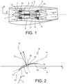
- turbomachines have a double flow, and a brief description will be made of them by means of the figure 1 .
- the rotor 1 is surrounded by a stator 2 comprising an inner casing 3, also called hub, and an outer casing 4, also called ferrule, concentric.
- a primary stream 5 extends between the rotor 1 and the inner casing 3, and a secondary stream 6 between the inner casing 3 and the outer casing 4.
- Compressors 7, 8, then turbines 9, 10 extend along of the primary vein 5 upstream and downstream of a combustion chamber 11.
- the machine also comprises a fan 12 upstream of the veins 5 and 6, composed of rotating blades whose tops extend to the outer casing 4 , and on the opposite side, a nozzle 13 where the veins 5 and 6 converge and their flows meet.
- the fan blades 12 provide an initial acceleration to the air entering the machine, coupled with compression and a significant helical component of motion.
- the stationary vanes extend in the outer vein 6 and also comprise an end part, such as a platform, radially inner connected to the inner casing 3, and an opposite end part, radially outer and which can also be a platform, connected to the outer casing 4.
- the vanes of the stator 14 have a structural role, to ensure the suspension of the inner casing 3 to the possible exclusion of any other structure.
- vanes of the stator 14 Another possible function for the vanes of the stator 14 is to allow a heat exchange between the air of the outer duct 6 and a heat transfer fluid such as the oil lubricating the machine, drawn into a recycling circuit and subjected to heating. important. For this, he is made to traverse branches of the circuit which pass through at least some of the vanes of the rectifier 14, since the outer vein 6 remains a cold part of the machine, in the absence of combustion of the gases, and the compression of the gases by the fan 12 being moderate.
- the blade 15 will therefore be bent at each of its sections, especially around the axis Iz by the component denoted Tz of the forces exerted on the section S, perpendicular to this axis Iz which will be considered in connection with the invention.
- the main axis of inertia Iz typically forms a fairly small angle (20° to 30°) with the axial direction X of the machine and divides the section of the blade 15 into a central region 40, also limited by the central portion an extrados face 16, and a complementary region, comprising the leading edge 17 and the trailing edge 18, and here divided into two end regions 41 and 42, respectively comprising these edges.
- the accumulation of the pressure forces on all the sections of the blades 15 has the effect of deforming them in bending in the angular direction of the machine, and of producing a rotation of the outer casing 4 which has various disadvantages: bending and misalignment of the easements passing through blades 15 or downstream of them, misalignment of the radial shaft (used for the transmission of power between the actual turbine engine and ancillary equipment of starters, generators, etc.) with increased wear of the bearings and gears of the gears, and, in the case of a suspension of the inner casing 3 by the vanes 15, a misalignment of the nacelle structures and a possible blocking of the thrust reversers.
- a main object of the invention has been to counteract this rotation due to the helical component of the air flow from the fan 12 and the corresponding bending of the blades 15 of the stator 14.
- a first aspect of the invention is a fixed stator vane for a turbomachine fan, comprising two opposite ends intended to be mounted on an inner casing and an outer casing, concentric with the inner casing, of the turbomachine, the blade being hollow and traversed by a main duct for the circulation of a heat transfer fluid cooled by circulating in the blade, and extending, from a fluid inlet at one of the ends of the blade, in at least one part in height of the blade, the blade being composed of planar and stacked sections, each in a uniform position in a radial direction of the turbomachine and each composed of a central region and of at least one extreme region on either side other than a main axis of bending inertia of the section (and therefore belonging to the plane of the section), the extreme region including a leading edge and a trailing edge of the blade, such that, in each blade section of the height part of the au be, the main duct extends only in the central region, said main axis of inertia being
- the technical effect of the invention can be summed up like this.
- the fluid traversing the cavity of the blade being hotter, it produces thermal expansions.
- the blade undergoes a differential thermal expansion which produces a bending opposite to the bending produced by the aerodynamic forces, and therefore reduces or cancels the rotation of the outer casing with respect to the inner casing.
- This arrangement may or may not be retained for the entire height of the blades or for only a portion of this height, for example at the point where the aerodynamic compression is greatest.
- the central main duct, and the secondary ducts, when they exist, can all be divided into parallel ducts without changing the nature of the invention.
- turbomachine fan stator which may be dual-flow, comprising a stage of fixed blades according to the above.
- This rectifier can be located immediately downstream of a fan.
- a preferred embodiment of the rectifier is characterized by an arrangement for reversing the direction of circulation of the fluid either in the main duct or in the side ducts.
- the blade 15 equipped with the invention comprises an inner end 20 fixed to the inner casing 3, and an outer end 21 fixed to the outer casing 4.
- An oil lubrication circuit 22 is present in the machine, for example under the inner casing 3. It comprises a supply duct 23 through which the oil enters the blade 15 located downstream of a lubricated device where the oil has been exposed to friction and contact with hot solids (bearings by example) ; the oil is then hot, and able to transfer greater heat to the blade 15, and to produce greater local thermal expansion there.
- THE circuit further comprises an outlet duct 24 through which the oil leaves the blade 15; the oil which has then been cooled by passing through the blade 15, is less apt to give up heat, and produces smaller local thermal expansions.
- the supply duct 23 is extended into the blade 15 by a cavity called the central duct 25, in which the oil rises in the radial direction R or in the height of the blade 15 before arriving at a so-called upper connection.
- 26 (according to the orientation of the picture 3 , where "upper” is equivalent to “closer to the outer casing 4") where the oil flow is dispersed before falling back into side ducts 27 and 28, parallel to the central duct 25 and the cooled oil travels in the direction reverse, towards the inner end 20, before joining the outlet duct 24 which brings the oil to the lubricated device.
- the ducts 25, 27 and 28 extend over a part 29 of the height of the vane 15 which can encompass the entire height or almost of the vane 15, and it is in any case advantageous for them to extend across a main portion, encompassing the mid-height line 30 (mid-radial distance from the casings 3 and 4) and possibly comprising approximately half the height of the vane 15 between the said casings 3 and 4.
- the upper connection 26 can be close to the outer end 21, but this condition is not essential.
- the lubrication circuit 22 could extend into the outer casing 4, and the general layout of the ducts 25, 27 and 28 would then be reversed.
- the lateral ducts 27 and 28 could be omitted, as well as the upper connection 26, and the supply duct 23 and the outlet duct 24 would then both branch off at opposite ends of the central duct. 25 extending into the inner casing 3 for one, in the outer casing 4 for the other.
- the central duct 25 extends in the central region 40 and therefore between the central portion of the extrados face 16 and the main axis of inertia Iz, so that the most significant thermal expansions produced by the heat released by the oil benefit the regions of the blade 15 which undergo the most the compression produced by the aerodynamic forces.
- the side ducts 27 and 28 are advantageous for the side ducts 27 and 28 to extend in the extreme regions 41 and 42.
- the central duct 25 occupies most of the area of the central region 40; and the side ducts 27 and 28 can occupy the greater part of the surface areas of the end regions 41 and 42 respectively.
- Relatively thin partitions of uniform thickness delimit the blade 15 and separate the ducts 25, 27 and 28.
- One of these partitions 43 separates the central duct 25 from the lateral duct 27 located towards the leading edge 17, the other of these partitions 44 separates the central duct 25 from the other lateral duct 28, located towards the trailing edge 18.
- the partitions 42 and 43 extend, in this embodiment, approximately in the extension of one of the other and at the location of the main axis Iz.
- the central duct 25 extends exclusively in the side of the blade 15 which undergoes compression.
- the side ducts 27 and 28 extend on the other side of the axis Iz. They could also occupy part of the central region 40.
- the various ducts 25, 27 and 28 could all be divided into several parallel ducts. In the embodiment shown, they are all straight, which is not essential.
- the wall thicknesses of the blade 15 are identical on the side of the upper surface 16 and on the side of the lower surface 19 for the various ducts 25, 26 and 27, which is not essential either, and the central duct 25 could for example be closer to the extrados 16.
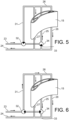
- the preceding oil circuit is completed by a bypass 31, connecting to the upper connector 26 one of the supply 23 and outlet 24 conduits via a first valve 32; a lower connector 33 between the conduits 25, 27 and 28, at the end opposite the upper connector 26 is added; and a second valve 34, installed on the same supply 23 or outlet 24 conduit as the first valve 32, is arranged at the junction of the conduit which extends it into the vane 15 (here the central conduit 25) of the lower fitting 33.
- “upper” and “lower” refer to the orientation of the figure 3 , 5 and 6 and equivalent to “closer to outer casing 4" and “closer to inner casing 3" respectively.
- the first valve 32 closes the bypass 31 and the second valve 34 closes the communication between the central duct 25 and the lower connection 33: the operation is the same as before, with reverse oil circulations between the central duct 25 and the side conduits 27 and 28, the valves 32 and 34 allowing the circulation of the supply conduit 23 towards the central conduit 25.
- the hot oil is sent to the bypass 31, then to the upper connection 26, before flowing in the same direction, towards the bottom of the figure, in the three conduits 25 , 27 and 28.
- the second valve 34 then allows communication between the central duct 25 and the lower connection 33, which allows the oil having passed through the central duct 25 to reach the outlet duct 24 directly.
Landscapes
- Engineering & Computer Science (AREA)
- Mechanical Engineering (AREA)
- General Engineering & Computer Science (AREA)
- Chemical & Material Sciences (AREA)
- Combustion & Propulsion (AREA)
- Physics & Mathematics (AREA)
- Fluid Mechanics (AREA)
- Structures Of Non-Positive Displacement Pumps (AREA)
Description
- Le sujet de l'invention est une aube fixe de redresseur d'une soufflante de turbomachine, un redresseur de soufflante de turbomachine, ainsi qu'une turbomachine.
- Certaines turbomachines connues comportent un double flux, et on en fera une description succincte au moyen de la
figure 1 . Le rotor 1 est entouré par un stator 2 comportant un carter intérieur 3, appelé aussi moyeu, et un carter extérieur 4, appelé aussi virole, concentriques. Une veine primaire 5 s'étend entre le rotor 1 et le carter intérieur 3, et une veine secondaire 6 entre le carter intérieur 3 et le carter extérieur 4. Des compresseurs 7, 8, puis des turbines 9, 10 s'étendent le long de la veine primaire 5 en amont et en aval d'une chambre de combustion 11. La machine comprend encore une soufflante 12 en amont des veines 5 et 6, composée d'aubes tournantes dont les sommets s'étendent jusqu'au carter extérieur 4, et à l'opposé, une tuyère 13 où les veines 5 et 6 convergent et leurs flux se rejoignent. Les aubes de la soufflante 12 offrent une première accélération à l'air entrant dans la machine, jointe à une compression et à une composante importante hélicoïdale de mouvement. Un redresseur 14, composé d'aubes fixes (souvent appelées OGV ou « Outlet Guide Vanes »), est ajouté pour redresser l'écoulement dans la veine extérieure 6, c'est-à-dire pour atténuer cette composante hélicoïdale d'écoulement. Les aubes fixes s'étendent dans la veine extérieure 6 et comprennent encore une partie d'extrémité, telle qu'une plate-forme, radialement intérieure reliée au carter intérieur 3, et une partie d'extrémité opposée, radialement extérieure et pouvant aussi être une plate-forme, reliée au carter extérieur 4. Dans certaines conceptions, les aubes du redresseur 14 ont un rôle structural, d'assurer la suspension du carter intérieur 3 à l'exclusion éventuellement de toute autre structure. - Une autre fonction possible pour les aubes du redresseur 14 est de permettre un échange de chaleur entre l'air de la veine extérieure 6 et un fluide caloporteur tel que l'huile lubrifiant la machine, entraînée dans un circuit de recyclage et soumise à un échauffement important. On lui fait parcourir pour cela des branches du circuit qui passent à travers certaines au moins des aubes du redresseur 14, puisque la veine extérieure 6 reste une partie froide de la machine, en l'absence de combustion des gaz, et la compression des gaz par la soufflante 12 étant modérée.
- On observe que les aubes du redresseur 14 sont fortement sollicitées par la pression du flux secondaire et subissent des flexions qui peuvent être importantes. Comme le montre la
figure 2 , des filets d'air incidents V arrivent sur les aubes 15 du redresseur 14 en faisant un angle avec elles dans la région de bords d'attaque 17, avant d'être redressés pour former un écoulement de sortie W sensiblement dans la direction axiale X de la machine, après avoir glissé sur des faces d'intrados 19 et quitté les aubes 15 par des bords de fuite 18. Les sollicitations exercées par la réaction de l'air sur les aubes 15 qui le dévient se traduisent par des forces de flexion. On va maintenant considérer une division de l'aube 15 en sections empilées, dont chacune est à une hauteur, ou à une position radiale, uniforme, entre les extrémités de l'aube 15 raccordées au carter intérieur 3 et au carter extérieur 4. Ces sections de l'aube 15, perpendiculaires à une direction radiale R perpendiculaire à la direction axiale X, possèdent des moments quadratiques d'inertie (calculables par la formule classique
- Le cumul des efforts de pression sur toutes les sections des aubes 15 a pour effet de les déformer en flexion dans la direction angulaire de la machine, et de produire une rotation du carter extérieur 4 qui a divers inconvénients : flexion et désalignement des servitudes passant par les aubes 15 ou en aval d'elles, désalignement de l'arbre radial (utilisé pour la transmission de puissance entre la turbomachine proprement dite et des équipements annexes de démarreurs, générateurs, etc.) avec une usure accrue des paliers et dentures d'engrenages, et, dans le cas d'une suspension du carter intérieur 3 par les aubes 15, un désalignement des structures de nacelle et un blocage possible des inverseurs de poussée.
- Un but principal de l'invention a été de contrecarrer cette rotation due à la composante hélicoïdale de l'écoulement d'air issu de la soufflante 12 et la flexion correspondante des aubes 15 du redresseur 14.
- L'art antérieur proche comprend
WO 02/38938 A1 US 2014/165570 A1 ,EP 3 179 048 A1 etUS 2017/284417 A1 . - Un premier aspect de l'invention est une aube fixe de redresseur d'une soufflante de turbomachine, comprenant deux extrémités opposées destinées à être montées sur un carter intérieur et un carter extérieur, concentrique au carter intérieur, de la turbomachine, l'aube étant creuse et parcourue par un conduit principal de circulation d'un fluide caloporteur refroidi en circulant dans l'aube, et s'étendant, à partir d'une entrée du fluide à une première des extrémités de l'aube, dans au moins une partie de hauteur de l'aube, l'aube étant composée de sections planes et empilées, chacune à une position uniforme dans une direction radiale de la turbomachine et chacune composées d'une région centrale et d'au moins une région extrême de part et d'autre d'un axe principal d'inertie de flexion de la section (et appartenant donc au plan de la section), la région extrême incluant un bord d'attaque et un bord de fuite de l'aube, telle que, dans chaque section d'aube de la partie de hauteur de l'aube, le conduit principal s'étend seulement dans la région centrale, ledit axe principal d'inertie étant un axe autour duquel la section a un moment quadratique d'inertie minimal et l'aube a une rigidité en flexion la plus petite ; l'aube est aussi parcourue, dans la partie de hauteur de l'aube, par des conduits latéraux de circulation du fluide s'étendant entre le conduit principal et, respectivement, le bord d'attaque et le bord de fuite de l'aube, les conduits latéraux s'étendant entre une sortie du fluide et un premier raccord, joignant des extrémités des conduits latéraux à une extrémité du conduit principal, et les conduits latéraux s'étendent, dans chaque section de la partie de hauteur de l'aube, dans ladite région extrême.
- L'effet technique de l'invention peut être résumé comme ceci. La flexion, s'exerçant dans l'aube entre son rayon intérieur et son rayon extérieur, la déforme en exerçant une contraction dans la région centrale et une dilatation dans les régions extrêmes. Le fluide parcourant la cavité de l'aube étant plus chaud, il produit des dilatations thermiques. En faisant exercer cette dilatation dans la région centrale, l'aube subit une dilatation thermique différentielle qui produit une flexion opposée à la flexion produite par les efforts aérodynamiques, et réduit ou annule donc la rotation du carter extérieur par rapport au carter intérieur.
- Cette disposition peut être retenue ou non pour toute la hauteur des aubes ou pour une portion seulement de cette hauteur, par exemple à l'endroit où la compression aérodynamique est la plus forte.
- En renforçant les aubes 15 de cette façon, il sera possible de les alléger en renonçant à des renforts statiques ou des augmentations d'épaisseur indispensables autrement.
- Comme l'aube est aussi parcourue, dans la partie principale, par des conduits secondaires de circulation du fluide assurant le retour de celui-ci vers le circuit de lubrification en sens opposé au conduit principal, et que les conduits secondaires s'étendent dans les régions extrêmes, les retours du fluide, refroidi et donc moins apte à contribuer à la dilatation thermique différentielle, restent à l'écart de la région centrale, qui peut être occupée plus complètement par le conduit principal, plus utile à l'effet de l'invention.
- Le conduit principal central, et les conduits secondaires, quand ils existent, peuvent tous être divisés en conduits parallèles sans changer à la nature de l'invention. Dans des réalisations complexes, on pourra donc trouver un réseau de conduits dans la région centrale, assurant plus particulièrement l'effet de l'invention et occupant éventuellement toute la région centrale ou la plupart de sa superficie, et un ou deux réseaux de conduits secondaires d'un côté ou des deux côtés du réseau central, éventuellement mais pas nécessairement disposés dans les régions extrêmes, sans imbrication des réseaux les uns dans les autres, l'axe principal d'inertie les séparant complètement dans des réalisations particulièrement caractéristiques.
- Un autre aspect de l'invention est un redresseur de soufflante de turbomachine, pouvant être à double flux, comprenant un étage d'aubes fixes selon ce qui précède. Ce redresseur peut être situé immédiatement en aval d'une soufflante.
- Et une réalisation préférée du redresseur est caractérisée par un agencement d'inversion de sens de circulation du fluide soit dans le conduit principal, soit dans les conduits latéraux.
- Les différents aspects, caractéristiques et avantages de l'invention seront maintenant décrits plus en détail au moyen des figures suivantes, qui représentent certaines réalisations préférées, mais purement illustratives de celle-ci :
- la
figure 1 , déjà décrite, représente une turbomachine à double flux ; - la
figure 2 , également décrite, évoque le problème technique résolu par l'invention ; - la
figure 3 représente une coupe transversale d'une aube conforme à l'invention ; - la
figure 4 représente une vue en perspective de l'aube ; et - les
figures 5 et 6 représentent chacune une illustration schématique d'une variante de réalisation. - On se reporte directement aux
figures 3 et 4 . L'aube 15 équipée de l'invention comporte une extrémité intérieure 20 fixée au carter intérieur 3, et une extrémité extérieure 21 fixée au carter extérieur 4. Un circuit de lubrification 22 à l'huile est présent dans la machine, par exemple sous le carter intérieur 3. Il comprend un conduit d'alimentation 23 par laquelle l'huile entre dans l'aube 15 situé en aval d'un dispositif lubrifié où l'huile a été exposée à des frottements et des contacts de solides chauds (paliers par exemple) ; l'huile est alors chaude, et apte à céder une chaleur plus importante à l'aube 15, et y produire une dilatation thermique locale plus grande. Le circuit comprend encore un conduit de sortie 24 par lequel l'huile sort de l'aube 15 ; l'huile qui a alors été refroidie par le passage dans l'aube 15, est moins apte à céder de la chaleur, et produit des dilatations thermiques locales plus petites. Le conduit d'alimentation 23 se prolonge dans l'aube 15 par une cavité appelée conduit central 25, dans lequel l'huile s'élève en direction radiale R ou de hauteur de l'aube 15 avant d'arriver à un raccord dit supérieur 26 (d'après l'orientation de lafigure 3 , où « supérieur » équivaut à « plus proche du carter extérieur 4 ») où l'écoulement d'huile se disperse avant de retomber dans des conduits latéraux 27 et 28, parallèles au conduit central 25 et que l'huile refroidie parcourt en sens inverse, vers l'extrémité intérieure 20, avant de rejoindre le conduit de sortie 24 qui ramène l'huile au dispositif lubrifié. Les conduits 25, 27 et 28 s'étendent sur une partie 29 de hauteur de l'aube 15 qui peut englober toute la hauteur ou presque de l'aube 15, et il est en tout cas avantageux qu'ils s'étendent à travers une portion principale, englobant la ligne de mi-hauteur 30 (à mi-distance radiale des carters 3 et 4) et pouvant comprendre environ la moitié de la hauteur de l'aube 15 entre lesdits carters 3 et 4. Le raccord supérieur 26 peut être proche de l'extrémité extérieure 21, mais cette condition n'est pas indispensable. Dans d'autres réalisations possibles de l'invention, le circuit de lubrification 22 pourrait s'étendre dans le carter extérieur 4, et la disposition générale des conduits 25, 27 et 28 serait alors inversée. Dans d'autres réalisations encore possibles, les conduits 27 et 28 latéraux pourraient être omis, ainsi que le raccord supérieur 26, et le conduit d'alimentation 23 et le conduit de sortie 24 se brancheraient alors tous deux à des extrémités opposées du conduit central 25 en s'étendant dans le carter intérieur 3 pour l'un, dans le carter extérieur 4 pour l'autre. - Il est préconisé, au moins pour la partie 29 de hauteur de l'aube 15, que le conduit central 25 s'étende dans la région centrale 40 et donc entre la portion centrale de la face d'extrados 16 et l'axe principal d'inertie Iz, afin que les dilatations thermiques les plus importantes produites par la chaleur cédée par l'huile bénéficient aux régions de l'aube 15 qui subissent le plus la compression produite par les efforts aérodynamiques. Les conduits latéraux 27 et 28, étant parcourus par de l'huile déjà refroidie, exercent des dilatations thermiques moins importantes : il est donc indiqué que ces dilatations soient situées à des endroits de l'aube 15 qui, étant en moyenne plus proches de l'axe principal Iz, voire du côté opposé de cet axe, subissent moins de compression produite par la flexion aérodynamique ou subissent au contraire une extension. C'est pourquoi, il est avantageux que les conduits latéraux 27 et 28 s'étendent dans les régions extrêmes 41 et 42. L'axe principal d'inertie Iz pour lequel le moment d'inertie quadratique de la section est minimal, et la résistance de l'aube 15 à la flexion et à cette section est aussi minimale, sépare donc parfaitement le conduit central 25 des conduits latéraux 27 et 28 de retour de fluide caloporteur. Avantageusement, le conduit central 25 occupe la plus grande partie de la superficie de la région centrale 40 ; et les conduits latéraux 27 et 28 peuvent occuper la plus grande partie des superficies des régions extrêmes 41 et 42 respectives.
- Des cloisons relativement minces et d'épaisseur uniforme délimitent l'aube 15 et séparent les conduits 25, 27 et 28. Une de ces cloisons 43 sépare le conduit central 25 du conduit latéral 27 situé vers le bord d'attaque 17, l'autre de ces cloisons 44 sépare le conduit central 25 de l'autre conduit latéral 28, situé vers le bord de fuite 18. Les cloisons 42 et 43 s'étendent, dans cette réalisation, à peu près dans le prolongement l'une de l'autre et à l'endroit de l'axe principal Iz. Ainsi, le conduit central 25 s'étend exclusivement dans le côté de l'aube 15 qui subit la compression. Dans cette réalisation, les conduits latéraux 27 et 28 s'étendent de l'autre côté de l'axe Iz. Ils pourraient aussi occuper une partie de la région centrale 40.
- Les différents conduits 25, 27 et 28 pourraient tous être divisés en plusieurs conduits parallèles. Dans la réalisation représentée, ils sont tous rectilignes, ce qui n'est pas indispensable. Les épaisseurs de parois de l'aube 15 sont identiques du côté de l'extrados 16 et du côté de l'intrados 19 pour les différents conduits 25, 26 et 27, ce qui n'est pas non plus indispensable, et le conduit central 25 pourrait par exemple être plus proche de l'extrados 16.
- On voit que l'effet technique de l'invention est produit surtout par le conduit central 25, les conduits latéraux 27 et 28 n'étant pas indispensables (ou pouvant être laissés vides d'huile). On peut alors proposer un agencement un peu plus complexe, représenté aux
figures 5 et 6 , pour produire à volonté un mode de fonctionnement différent, dans lequel la dilatation thermique différentielle n'est pas exploitée. En se reportant auxfigures 5 et 6 , le circuit d'huile précédent est complété par une dérivation 31, reliant au raccord supérieur 26 l'un des conduits d'alimentation 23 et de sortie 24 par une première vanne 32 ; un raccord inférieur 33 entre les conduits 25, 27 et 28, à l'extrémité opposée au raccord supérieur 26 est ajouté ; et une deuxième vanne 34, installée sur le même conduit d'alimentation 23 ou de sortie 24 que la première vanne 32, est disposée à la jonction du conduit qui le prolonge dans l'aube 15 (ici le conduit central 25) du raccord inférieur 33. Ici aussi, « supérieur » et « inférieur » font référence à l'orientation desfigures 3 ,5 et 6 et équivalent à « plus proche du carter extérieur 4 » et « plus proche du carter intérieur 3 » respectivement. - A l'état de la
figure 5 , la première vanne 32 ferme la dérivation 31 et la seconde vanne 34 ferme la communication entre le conduit central 25 et le raccord inférieur 33 : le fonctionnement est le même que précédemment, avec des circulations d'huile inverses entre le conduit central 25 et les conduits latéraux 27 et 28, les vannes 32 et 34 permettant la circulation du conduit d'alimentation 23 vers le conduit central 25. Mais à l'état de lafigure 6 où les deux vannes 32 et 34 sont commutées, l'huile chaude est envoyée dans la dérivation 31, puis dans le raccord supérieur 26, avant de s'écouler dans le même sens, vers le bas de la figure, dans les trois conduits 25, 27 et 28. La seconde vanne 34 permet alors une communication entre le conduit central 25 et le raccord inférieur 33, ce qui permet à l'huile ayant parcouru le conduit central 25 de parvenir directement au conduit de sortie 24. - L'invention a été décrite en liaison à un circuit de lubrification à l'huile. Elle pourrait être mise en pratique avec d'autres fluides caloporteurs, sans changement de forme de l'aube 15, qui offriraient la même relation d'échange de chaleur.
Claims (5)
- Aube (15) fixe de redresseur d'une soufflante (12) de turbomachine, comprenant deux extrémités (20, 21) opposées destinées à être montées sur un carter intérieur (3) et un carter extérieur (4), concentrique au carter intérieur, de la turbomachine, l'aube étant creuse et parcourue par un conduit principal (25) de circulation d'un fluide caloporteur refroidi en circulant dans l'aube, et s'étendant, à partir d'une entrée du fluide (23) à une première des extrémités (20) de l'aube, dans au moins une partie (29) de hauteur de l'aube, l'aube étant composée de sections, chacune à une position uniforme dans une direction radiale (R) de la turbomachine, les sections étant chacune composées d'une région centrale (40) et d'au moins une région extrême (41, 42) de part et d'autre d'un axe principal d'inertie (Iz) de flexion de la section, la région extrême (41, 42) incluant un bord d'attaque (17) et un bord de fuite (18) de l'aube, caractérisée en ce que, dans chaque section d'aube de la partie de hauteur de l'aube, le conduit principal (25) s'étend seulement dans la région centrale (40), ledit axe principal d'inertie (Iz) étant un axe autour duquel la section a un moment quadratique d'inertie minimal et l'aube (15) a une rigidité en flexion la plus petite ; l'aube est aussi parcourue, dans la partie de hauteur de l'aube, par des conduits latéraux (27, 28) de circulation du fluide s'étendant entre le conduit principal et, respectivement, le bord d'attaque (17) et le bord de fuite (18) de l'aube, les conduits latéraux s'étendant entre une sortie du fluide (24) et un premier raccord (26), joignant des extrémités des conduits latéraux à une extrémité du conduit principal, et les conduits latéraux (27, 28) s'étendent, dans chaque section de la partie de hauteur de l'aube, dans ladite région extrême (41, 42).
- Redresseur (14) de soufflante de turbomachine, comprenant un étage composé d'aubes (15) selon la revendication précédente.
- Redresseur selon la revendication 2, caractérisé en ce qu'il comprend un agencement (31, 32, 33, 34) d'inversion de sens de circulation d'huile soit dans le conduit principal, soit dans les conduits latéraux.
- Turbomachine, comprenant une veine secondaire (6) et au moins une aube fixe selon la revendication 1.
- Turbomachine, comprenant une soufflante (12) et le redresseur selon la revendication 3, immédiatement en aval de la soufflante.
Applications Claiming Priority (2)
| Application Number | Priority Date | Filing Date | Title |
|---|---|---|---|
| FR1762890A FR3075870B1 (fr) | 2017-12-21 | 2017-12-21 | Aube fixe de turbomachine, dans un redresseur de soufflante |
| PCT/FR2018/053335 WO2019122657A1 (fr) | 2017-12-21 | 2018-12-17 | Aube fixe de redresseur d'une soufflante de turbomachine |
Publications (2)
| Publication Number | Publication Date |
|---|---|
| EP3728793A1 EP3728793A1 (fr) | 2020-10-28 |
| EP3728793B1 true EP3728793B1 (fr) | 2023-03-08 |
Family
ID=61750347
Family Applications (1)
| Application Number | Title | Priority Date | Filing Date |
|---|---|---|---|
| EP18833285.2A Active EP3728793B1 (fr) | 2017-12-21 | 2018-12-17 | Aube fixe de redresseur d'une soufflante de turbomachine |
Country Status (5)
| Country | Link |
|---|---|
| US (1) | US11149566B2 (fr) |
| EP (1) | EP3728793B1 (fr) |
| CN (1) | CN111566318B (fr) |
| FR (1) | FR3075870B1 (fr) |
| WO (1) | WO2019122657A1 (fr) |
Families Citing this family (19)
| Publication number | Priority date | Publication date | Assignee | Title |
|---|---|---|---|---|
| US11448132B2 (en) | 2020-01-03 | 2022-09-20 | Raytheon Technologies Corporation | Aircraft bypass duct heat exchanger |
| EP3899400B1 (fr) | 2020-01-03 | 2024-03-06 | RTX Corporation | Échangeur de chaleur de turbine à gaz |
| US12297775B2 (en) | 2020-01-03 | 2025-05-13 | Rtx Corporation | Aircraft heat exchanger panel array interconnection |
| US11674758B2 (en) | 2020-01-19 | 2023-06-13 | Raytheon Technologies Corporation | Aircraft heat exchangers and plates |
| US11525637B2 (en) | 2020-01-19 | 2022-12-13 | Raytheon Technologies Corporation | Aircraft heat exchanger finned plate manufacture |
| WO2021146674A1 (fr) | 2020-01-19 | 2021-07-22 | Raytheon Technologies Corporation | Échangeur de chaleur d'aéronef |
| US11585273B2 (en) | 2020-01-20 | 2023-02-21 | Raytheon Technologies Corporation | Aircraft heat exchangers |
| GB2591298B (en) * | 2020-01-27 | 2022-06-08 | Gkn Aerospace Sweden Ab | Outlet guide vane cooler |
| US11585605B2 (en) | 2020-02-07 | 2023-02-21 | Raytheon Technologies Corporation | Aircraft heat exchanger panel attachment |
| CN112943384A (zh) * | 2021-05-14 | 2021-06-11 | 成都中科翼能科技有限公司 | 一种用于涡轮导向叶片的冷气导管结构 |
| FR3130876B1 (fr) * | 2021-12-20 | 2024-09-13 | Safran Aircraft Engines | Aube de redresseur comportant un caloduc |
| US20230265862A1 (en) | 2022-02-21 | 2023-08-24 | General Electric Company | Turbofan engine having angled inlet pre-swirl vanes |
| US11725526B1 (en) | 2022-03-08 | 2023-08-15 | General Electric Company | Turbofan engine having nacelle with non-annular inlet |
| CN114857044B (zh) * | 2022-05-13 | 2023-09-12 | 清华大学 | 一种全气浮支承的多级对转轴流压气机 |
| US12196095B2 (en) * | 2022-11-29 | 2025-01-14 | Rtx Corporation | Gas turbine engine component having an airfoil with internal cross-ribs |
| US12209557B1 (en) | 2023-11-30 | 2025-01-28 | General Electric Company | Gas turbine engine with forward swept outlet guide vanes |
| US12385430B2 (en) | 2023-11-30 | 2025-08-12 | General Electric Company | Gas turbine engine with forward swept outlet guide vanes |
| US12228037B1 (en) | 2023-12-04 | 2025-02-18 | General Electric Company | Guide vane assembly with fixed and variable pitch inlet guide vanes |
| US12313021B1 (en) | 2024-03-14 | 2025-05-27 | General Electric Company | Outer nacelle with inlet guide vanes and acoustic treatment |
Family Cites Families (10)
| Publication number | Priority date | Publication date | Assignee | Title |
|---|---|---|---|---|
| US3394918A (en) * | 1966-04-13 | 1968-07-30 | Howmet Corp | Bimetallic airfoils |
| AU2001213231A1 (en) * | 2000-11-10 | 2002-05-21 | Marek Kovac | Bypass gas turbine engine and cooling method for working fluid |
| US6890154B2 (en) * | 2003-08-08 | 2005-05-10 | United Technologies Corporation | Microcircuit cooling for a turbine blade |
| US8500392B2 (en) * | 2009-10-01 | 2013-08-06 | Pratt & Whitney Canada Corp. | Sealing for vane segments |
| US8616834B2 (en) * | 2010-04-30 | 2013-12-31 | General Electric Company | Gas turbine engine airfoil integrated heat exchanger |
| US20140165570A1 (en) * | 2012-12-18 | 2014-06-19 | United Technologies Corporation | Oscillating heat pipe for thermal management of gas turbine engines |
| WO2015191039A1 (fr) * | 2014-06-10 | 2015-12-17 | Siemens Energy, Inc. | Moteur à turbine à gaz avec système de refroidissement à centrage de rotor dans un diffuseur d'échappement |
| US10196932B2 (en) * | 2015-12-08 | 2019-02-05 | General Electric Company | OGV heat exchangers networked in parallel and serial flow |
| FR3046811B1 (fr) * | 2016-01-15 | 2018-02-16 | Snecma | Aube directrice de sortie pour turbomachine d'aeronef, presentant une fonction amelioree de refroidissement de lubrifiant |
| FR3049644B1 (fr) * | 2016-04-01 | 2018-04-13 | Safran Aircraft Engines | Aube directrice de sortie pour turbomachine d'aeronef, presentant une fonction amelioree de refroidissement de lubrifiant a l'aide d'une matrice de conduction thermique logee dans un passage interieur de l'aube |
-
2017
- 2017-12-21 FR FR1762890A patent/FR3075870B1/fr active Active
-
2018
- 2018-12-17 US US16/955,449 patent/US11149566B2/en active Active
- 2018-12-17 EP EP18833285.2A patent/EP3728793B1/fr active Active
- 2018-12-17 CN CN201880082459.7A patent/CN111566318B/zh active Active
- 2018-12-17 WO PCT/FR2018/053335 patent/WO2019122657A1/fr not_active Ceased
Also Published As
| Publication number | Publication date |
|---|---|
| CN111566318B (zh) | 2022-08-12 |
| WO2019122657A1 (fr) | 2019-06-27 |
| EP3728793A1 (fr) | 2020-10-28 |
| US20200347737A1 (en) | 2020-11-05 |
| US11149566B2 (en) | 2021-10-19 |
| FR3075870B1 (fr) | 2021-09-17 |
| FR3075870A1 (fr) | 2019-06-28 |
| CN111566318A (zh) | 2020-08-21 |
Similar Documents
| Publication | Publication Date | Title |
|---|---|---|
| EP3728793B1 (fr) | Aube fixe de redresseur d'une soufflante de turbomachine | |
| EP3735518B1 (fr) | Turbomachine comportant un échangeur de chaleur dans la veine secondaire | |
| EP3444444B1 (fr) | Système d'aubes a calage variable de compresseur pour turbomachine | |
| EP2577068B1 (fr) | Générateurs de tourbillons en amont d'une grille d'aubes de compresseur | |
| FR3064682B1 (fr) | Carter intermediaire de turbomachine d'aeronef comprenant un embout de passage de lubrifiant connecte a une aube de carter par une piece de raccord | |
| FR2631386A1 (fr) | Turbomachine comportant une grille d'entree incorporant des tubes de passage d'huile | |
| FR3016956A1 (fr) | Echangeur de chaleur d'une turbomachine | |
| WO2018197232A1 (fr) | Ensemble propulsif pour aeronef comportant des echangeurs de chaleur air-liquide | |
| EP3698050B1 (fr) | Carter extérieur de turbo-compresseur avec réservoir d'huile intégré | |
| FR3051219A1 (fr) | Aube de turbomachine, telle par exemple qu'un turboreacteur ou un turbopropulseur d'avion | |
| WO2022123151A1 (fr) | Turbomachine pour un aéronef | |
| EP3906359B1 (fr) | Aube de turbomachine | |
| WO2019038510A1 (fr) | Turboreacteur a double corps ayant un palier de butee d'arbre basse pression positionne dans le carter d'echappement | |
| EP3673154B1 (fr) | Conduit de décharge d'un moyeu de carter intermédiaire pour turboréacteur d'aéronef comportant des canaux de refroidissement | |
| WO2017187093A1 (fr) | Ensemble de redressement de flux d'air et turbomachine comprenant un tel ensemble | |
| EP4483039B1 (fr) | Turbomachine pour aéronef | |
| WO2022262998A1 (fr) | Structure de turbomachine a trois flux | |
| FR3064295B1 (fr) | Carter intermediaire de turbomachine d'aeronef comprenant un embout de passage de lubrifiant solidaire d'une plateforme | |
| EP4374046B1 (fr) | Turbomachine pour aeronef avec echangeur de chaleur | |
| FR3093540A1 (fr) | Turbomachine double flux a gaz a bras echangeur thermique | |
| FR3099204A1 (fr) | Etage redresseur de turbomachine avec passage de fuite d’air de refroidissement a section variable suivant orientation des aubes |
Legal Events
| Date | Code | Title | Description |
|---|---|---|---|
| STAA | Information on the status of an ep patent application or granted ep patent |
Free format text: STATUS: UNKNOWN |
|
| STAA | Information on the status of an ep patent application or granted ep patent |
Free format text: STATUS: THE INTERNATIONAL PUBLICATION HAS BEEN MADE |
|
| PUAI | Public reference made under article 153(3) epc to a published international application that has entered the european phase |
Free format text: ORIGINAL CODE: 0009012 |
|
| STAA | Information on the status of an ep patent application or granted ep patent |
Free format text: STATUS: REQUEST FOR EXAMINATION WAS MADE |
|
| 17P | Request for examination filed |
Effective date: 20200609 |
|
| AK | Designated contracting states |
Kind code of ref document: A1 Designated state(s): AL AT BE BG CH CY CZ DE DK EE ES FI FR GB GR HR HU IE IS IT LI LT LU LV MC MK MT NL NO PL PT RO RS SE SI SK SM TR |
|
| AX | Request for extension of the european patent |
Extension state: BA ME |
|
| DAV | Request for validation of the european patent (deleted) | ||
| DAX | Request for extension of the european patent (deleted) | ||
| STAA | Information on the status of an ep patent application or granted ep patent |
Free format text: STATUS: EXAMINATION IS IN PROGRESS |
|
| 17Q | First examination report despatched |
Effective date: 20211004 |
|
| GRAP | Despatch of communication of intention to grant a patent |
Free format text: ORIGINAL CODE: EPIDOSNIGR1 |
|
| STAA | Information on the status of an ep patent application or granted ep patent |
Free format text: STATUS: GRANT OF PATENT IS INTENDED |
|
| INTG | Intention to grant announced |
Effective date: 20221125 |
|
| GRAS | Grant fee paid |
Free format text: ORIGINAL CODE: EPIDOSNIGR3 |
|
| GRAA | (expected) grant |
Free format text: ORIGINAL CODE: 0009210 |
|
| STAA | Information on the status of an ep patent application or granted ep patent |
Free format text: STATUS: THE PATENT HAS BEEN GRANTED |
|
| AK | Designated contracting states |
Kind code of ref document: B1 Designated state(s): AL AT BE BG CH CY CZ DE DK EE ES FI FR GB GR HR HU IE IS IT LI LT LU LV MC MK MT NL NO PL PT RO RS SE SI SK SM TR |
|
| REG | Reference to a national code |
Ref country code: CH Ref legal event code: EP Ref country code: AT Ref legal event code: REF Ref document number: 1552694 Country of ref document: AT Kind code of ref document: T Effective date: 20230315 |
|
| REG | Reference to a national code |
Ref country code: IE Ref legal event code: FG4D Free format text: LANGUAGE OF EP DOCUMENT: FRENCH |
|
| REG | Reference to a national code |
Ref country code: DE Ref legal event code: R096 Ref document number: 602018047072 Country of ref document: DE |
|
| REG | Reference to a national code |
Ref country code: LT Ref legal event code: MG9D |
|
| REG | Reference to a national code |
Ref country code: NL Ref legal event code: MP Effective date: 20230308 |
|
| PG25 | Lapsed in a contracting state [announced via postgrant information from national office to epo] |
Ref country code: RS Free format text: LAPSE BECAUSE OF FAILURE TO SUBMIT A TRANSLATION OF THE DESCRIPTION OR TO PAY THE FEE WITHIN THE PRESCRIBED TIME-LIMIT Effective date: 20230308 Ref country code: NO Free format text: LAPSE BECAUSE OF FAILURE TO SUBMIT A TRANSLATION OF THE DESCRIPTION OR TO PAY THE FEE WITHIN THE PRESCRIBED TIME-LIMIT Effective date: 20230608 Ref country code: LV Free format text: LAPSE BECAUSE OF FAILURE TO SUBMIT A TRANSLATION OF THE DESCRIPTION OR TO PAY THE FEE WITHIN THE PRESCRIBED TIME-LIMIT Effective date: 20230308 Ref country code: LT Free format text: LAPSE BECAUSE OF FAILURE TO SUBMIT A TRANSLATION OF THE DESCRIPTION OR TO PAY THE FEE WITHIN THE PRESCRIBED TIME-LIMIT Effective date: 20230308 Ref country code: HR Free format text: LAPSE BECAUSE OF FAILURE TO SUBMIT A TRANSLATION OF THE DESCRIPTION OR TO PAY THE FEE WITHIN THE PRESCRIBED TIME-LIMIT Effective date: 20230308 Ref country code: ES Free format text: LAPSE BECAUSE OF FAILURE TO SUBMIT A TRANSLATION OF THE DESCRIPTION OR TO PAY THE FEE WITHIN THE PRESCRIBED TIME-LIMIT Effective date: 20230308 |
|
| REG | Reference to a national code |
Ref country code: AT Ref legal event code: MK05 Ref document number: 1552694 Country of ref document: AT Kind code of ref document: T Effective date: 20230308 |
|
| PG25 | Lapsed in a contracting state [announced via postgrant information from national office to epo] |
Ref country code: SE Free format text: LAPSE BECAUSE OF FAILURE TO SUBMIT A TRANSLATION OF THE DESCRIPTION OR TO PAY THE FEE WITHIN THE PRESCRIBED TIME-LIMIT Effective date: 20230308 Ref country code: NL Free format text: LAPSE BECAUSE OF FAILURE TO SUBMIT A TRANSLATION OF THE DESCRIPTION OR TO PAY THE FEE WITHIN THE PRESCRIBED TIME-LIMIT Effective date: 20230308 Ref country code: GR Free format text: LAPSE BECAUSE OF FAILURE TO SUBMIT A TRANSLATION OF THE DESCRIPTION OR TO PAY THE FEE WITHIN THE PRESCRIBED TIME-LIMIT Effective date: 20230609 Ref country code: FI Free format text: LAPSE BECAUSE OF FAILURE TO SUBMIT A TRANSLATION OF THE DESCRIPTION OR TO PAY THE FEE WITHIN THE PRESCRIBED TIME-LIMIT Effective date: 20230308 |
|
| PG25 | Lapsed in a contracting state [announced via postgrant information from national office to epo] |
Ref country code: SM Free format text: LAPSE BECAUSE OF FAILURE TO SUBMIT A TRANSLATION OF THE DESCRIPTION OR TO PAY THE FEE WITHIN THE PRESCRIBED TIME-LIMIT Effective date: 20230308 Ref country code: RO Free format text: LAPSE BECAUSE OF FAILURE TO SUBMIT A TRANSLATION OF THE DESCRIPTION OR TO PAY THE FEE WITHIN THE PRESCRIBED TIME-LIMIT Effective date: 20230308 Ref country code: PT Free format text: LAPSE BECAUSE OF FAILURE TO SUBMIT A TRANSLATION OF THE DESCRIPTION OR TO PAY THE FEE WITHIN THE PRESCRIBED TIME-LIMIT Effective date: 20230710 Ref country code: EE Free format text: LAPSE BECAUSE OF FAILURE TO SUBMIT A TRANSLATION OF THE DESCRIPTION OR TO PAY THE FEE WITHIN THE PRESCRIBED TIME-LIMIT Effective date: 20230308 Ref country code: CZ Free format text: LAPSE BECAUSE OF FAILURE TO SUBMIT A TRANSLATION OF THE DESCRIPTION OR TO PAY THE FEE WITHIN THE PRESCRIBED TIME-LIMIT Effective date: 20230308 Ref country code: AT Free format text: LAPSE BECAUSE OF FAILURE TO SUBMIT A TRANSLATION OF THE DESCRIPTION OR TO PAY THE FEE WITHIN THE PRESCRIBED TIME-LIMIT Effective date: 20230308 |
|
| PG25 | Lapsed in a contracting state [announced via postgrant information from national office to epo] |
Ref country code: SK Free format text: LAPSE BECAUSE OF FAILURE TO SUBMIT A TRANSLATION OF THE DESCRIPTION OR TO PAY THE FEE WITHIN THE PRESCRIBED TIME-LIMIT Effective date: 20230308 Ref country code: PL Free format text: LAPSE BECAUSE OF FAILURE TO SUBMIT A TRANSLATION OF THE DESCRIPTION OR TO PAY THE FEE WITHIN THE PRESCRIBED TIME-LIMIT Effective date: 20230308 Ref country code: IS Free format text: LAPSE BECAUSE OF FAILURE TO SUBMIT A TRANSLATION OF THE DESCRIPTION OR TO PAY THE FEE WITHIN THE PRESCRIBED TIME-LIMIT Effective date: 20230708 |
|
| REG | Reference to a national code |
Ref country code: DE Ref legal event code: R097 Ref document number: 602018047072 Country of ref document: DE |
|
| PLBE | No opposition filed within time limit |
Free format text: ORIGINAL CODE: 0009261 |
|
| STAA | Information on the status of an ep patent application or granted ep patent |
Free format text: STATUS: NO OPPOSITION FILED WITHIN TIME LIMIT |
|
| PG25 | Lapsed in a contracting state [announced via postgrant information from national office to epo] |
Ref country code: SI Free format text: LAPSE BECAUSE OF FAILURE TO SUBMIT A TRANSLATION OF THE DESCRIPTION OR TO PAY THE FEE WITHIN THE PRESCRIBED TIME-LIMIT Effective date: 20230308 Ref country code: DK Free format text: LAPSE BECAUSE OF FAILURE TO SUBMIT A TRANSLATION OF THE DESCRIPTION OR TO PAY THE FEE WITHIN THE PRESCRIBED TIME-LIMIT Effective date: 20230308 |
|
| 26N | No opposition filed |
Effective date: 20231211 |
|
| PG25 | Lapsed in a contracting state [announced via postgrant information from national office to epo] |
Ref country code: IT Free format text: LAPSE BECAUSE OF FAILURE TO SUBMIT A TRANSLATION OF THE DESCRIPTION OR TO PAY THE FEE WITHIN THE PRESCRIBED TIME-LIMIT Effective date: 20230308 |
|
| REG | Reference to a national code |
Ref country code: CH Ref legal event code: PL |
|
| PG25 | Lapsed in a contracting state [announced via postgrant information from national office to epo] |
Ref country code: LU Free format text: LAPSE BECAUSE OF NON-PAYMENT OF DUE FEES Effective date: 20231217 |
|
| PG25 | Lapsed in a contracting state [announced via postgrant information from national office to epo] |
Ref country code: MC Free format text: LAPSE BECAUSE OF FAILURE TO SUBMIT A TRANSLATION OF THE DESCRIPTION OR TO PAY THE FEE WITHIN THE PRESCRIBED TIME-LIMIT Effective date: 20230308 |
|
| REG | Reference to a national code |
Ref country code: BE Ref legal event code: MM Effective date: 20231231 |
|
| PG25 | Lapsed in a contracting state [announced via postgrant information from national office to epo] |
Ref country code: MC Free format text: LAPSE BECAUSE OF FAILURE TO SUBMIT A TRANSLATION OF THE DESCRIPTION OR TO PAY THE FEE WITHIN THE PRESCRIBED TIME-LIMIT Effective date: 20230308 Ref country code: LU Free format text: LAPSE BECAUSE OF NON-PAYMENT OF DUE FEES Effective date: 20231217 |
|
| REG | Reference to a national code |
Ref country code: IE Ref legal event code: MM4A |
|
| PG25 | Lapsed in a contracting state [announced via postgrant information from national office to epo] |
Ref country code: IE Free format text: LAPSE BECAUSE OF NON-PAYMENT OF DUE FEES Effective date: 20231217 |
|
| PG25 | Lapsed in a contracting state [announced via postgrant information from national office to epo] |
Ref country code: BE Free format text: LAPSE BECAUSE OF NON-PAYMENT OF DUE FEES Effective date: 20231231 |
|
| PG25 | Lapsed in a contracting state [announced via postgrant information from national office to epo] |
Ref country code: CH Free format text: LAPSE BECAUSE OF NON-PAYMENT OF DUE FEES Effective date: 20231231 |
|
| PG25 | Lapsed in a contracting state [announced via postgrant information from national office to epo] |
Ref country code: IE Free format text: LAPSE BECAUSE OF NON-PAYMENT OF DUE FEES Effective date: 20231217 Ref country code: CH Free format text: LAPSE BECAUSE OF NON-PAYMENT OF DUE FEES Effective date: 20231231 Ref country code: BE Free format text: LAPSE BECAUSE OF NON-PAYMENT OF DUE FEES Effective date: 20231231 |
|
| PG25 | Lapsed in a contracting state [announced via postgrant information from national office to epo] |
Ref country code: BG Free format text: LAPSE BECAUSE OF FAILURE TO SUBMIT A TRANSLATION OF THE DESCRIPTION OR TO PAY THE FEE WITHIN THE PRESCRIBED TIME-LIMIT Effective date: 20230308 |
|
| PG25 | Lapsed in a contracting state [announced via postgrant information from national office to epo] |
Ref country code: BG Free format text: LAPSE BECAUSE OF FAILURE TO SUBMIT A TRANSLATION OF THE DESCRIPTION OR TO PAY THE FEE WITHIN THE PRESCRIBED TIME-LIMIT Effective date: 20230308 |
|
| PG25 | Lapsed in a contracting state [announced via postgrant information from national office to epo] |
Ref country code: CY Free format text: LAPSE BECAUSE OF FAILURE TO SUBMIT A TRANSLATION OF THE DESCRIPTION OR TO PAY THE FEE WITHIN THE PRESCRIBED TIME-LIMIT; INVALID AB INITIO Effective date: 20181217 |
|
| PG25 | Lapsed in a contracting state [announced via postgrant information from national office to epo] |
Ref country code: HU Free format text: LAPSE BECAUSE OF FAILURE TO SUBMIT A TRANSLATION OF THE DESCRIPTION OR TO PAY THE FEE WITHIN THE PRESCRIBED TIME-LIMIT; INVALID AB INITIO Effective date: 20181217 |
|
| PG25 | Lapsed in a contracting state [announced via postgrant information from national office to epo] |
Ref country code: TR Free format text: LAPSE BECAUSE OF FAILURE TO SUBMIT A TRANSLATION OF THE DESCRIPTION OR TO PAY THE FEE WITHIN THE PRESCRIBED TIME-LIMIT Effective date: 20230308 |
|
| PGFP | Annual fee paid to national office [announced via postgrant information from national office to epo] |
Ref country code: GB Payment date: 20251229 Year of fee payment: 8 |
|
| PGFP | Annual fee paid to national office [announced via postgrant information from national office to epo] |
Ref country code: FR Payment date: 20251222 Year of fee payment: 8 |
|
| PGFP | Annual fee paid to national office [announced via postgrant information from national office to epo] |
Ref country code: DE Payment date: 20251222 Year of fee payment: 8 |