EP3728088B1 - Method and device for grouping floating articles into batches, with dynamic hydraulic superimposition of the articles - Google Patents
Method and device for grouping floating articles into batches, with dynamic hydraulic superimposition of the articles Download PDFInfo
- Publication number
- EP3728088B1 EP3728088B1 EP18819549.9A EP18819549A EP3728088B1 EP 3728088 B1 EP3728088 B1 EP 3728088B1 EP 18819549 A EP18819549 A EP 18819549A EP 3728088 B1 EP3728088 B1 EP 3728088B1
- Authority
- EP
- European Patent Office
- Prior art keywords
- objects
- accumulation channel
- accumulation
- channel
- superposition
- Prior art date
- Legal status (The legal status is an assumption and is not a legal conclusion. Google has not performed a legal analysis and makes no representation as to the accuracy of the status listed.)
- Active
Links
- 238000000034 method Methods 0.000 title claims description 27
- 238000007667 floating Methods 0.000 title description 21
- 238000009825 accumulation Methods 0.000 claims description 315
- 238000011144 upstream manufacturing Methods 0.000 claims description 106
- 230000000694 effects Effects 0.000 claims description 25
- 238000013519 translation Methods 0.000 claims description 7
- 230000001680 brushing effect Effects 0.000 claims description 5
- 238000004891 communication Methods 0.000 claims description 2
- 238000007599 discharging Methods 0.000 claims 1
- 230000003134 recirculating effect Effects 0.000 claims 1
- 238000001514 detection method Methods 0.000 description 13
- 238000006073 displacement reaction Methods 0.000 description 11
- 230000001133 acceleration Effects 0.000 description 9
- 235000013399 edible fruits Nutrition 0.000 description 9
- 238000009434 installation Methods 0.000 description 8
- 235000013311 vegetables Nutrition 0.000 description 6
- 238000004804 winding Methods 0.000 description 6
- 230000014759 maintenance of location Effects 0.000 description 5
- 241000220225 Malus Species 0.000 description 4
- 241001417494 Sciaenidae Species 0.000 description 4
- 235000021016 apples Nutrition 0.000 description 4
- 230000008901 benefit Effects 0.000 description 4
- 230000006866 deterioration Effects 0.000 description 4
- 239000007788 liquid Substances 0.000 description 4
- 230000000717 retained effect Effects 0.000 description 4
- 230000035939 shock Effects 0.000 description 4
- 238000004458 analytical method Methods 0.000 description 3
- 238000007654 immersion Methods 0.000 description 3
- 230000008569 process Effects 0.000 description 3
- 238000012545 processing Methods 0.000 description 3
- 230000000750 progressive effect Effects 0.000 description 3
- 238000004140 cleaning Methods 0.000 description 2
- 238000004806 packaging method and process Methods 0.000 description 2
- 238000005096 rolling process Methods 0.000 description 2
- 238000012360 testing method Methods 0.000 description 2
- 238000012549 training Methods 0.000 description 2
- 238000012546 transfer Methods 0.000 description 2
- 239000003643 water by type Substances 0.000 description 2
- 101100536354 Drosophila melanogaster tant gene Proteins 0.000 description 1
- 235000007688 Lycopersicon esculentum Nutrition 0.000 description 1
- 241000220324 Pyrus Species 0.000 description 1
- 240000003768 Solanum lycopersicum Species 0.000 description 1
- 240000008042 Zea mays Species 0.000 description 1
- 239000000654 additive Substances 0.000 description 1
- 238000012550 audit Methods 0.000 description 1
- 230000004888 barrier function Effects 0.000 description 1
- 230000008878 coupling Effects 0.000 description 1
- 238000010168 coupling process Methods 0.000 description 1
- 238000005859 coupling reaction Methods 0.000 description 1
- 238000010586 diagram Methods 0.000 description 1
- 235000013305 food Nutrition 0.000 description 1
- 238000003384 imaging method Methods 0.000 description 1
- 230000006872 improvement Effects 0.000 description 1
- 238000004519 manufacturing process Methods 0.000 description 1
- 230000003287 optical effect Effects 0.000 description 1
- 235000021017 pears Nutrition 0.000 description 1
- 230000001737 promoting effect Effects 0.000 description 1
- 238000005086 pumping Methods 0.000 description 1
- 230000000630 rising effect Effects 0.000 description 1
- 230000001960 triggered effect Effects 0.000 description 1
- XLYOFNOQVPJJNP-UHFFFAOYSA-N water Substances O XLYOFNOQVPJJNP-UHFFFAOYSA-N 0.000 description 1
- 238000005303 weighing Methods 0.000 description 1
Images


Classifications
-
- B—PERFORMING OPERATIONS; TRANSPORTING
- B65—CONVEYING; PACKING; STORING; HANDLING THIN OR FILAMENTARY MATERIAL
- B65G—TRANSPORT OR STORAGE DEVICES, e.g. CONVEYORS FOR LOADING OR TIPPING, SHOP CONVEYOR SYSTEMS OR PNEUMATIC TUBE CONVEYORS
- B65G51/00—Conveying articles through pipes or tubes by fluid flow or pressure; Conveying articles over a flat surface, e.g. the base of a trough, by jets located in the surface
- B65G51/01—Hydraulic transport of articles
-
- B—PERFORMING OPERATIONS; TRANSPORTING
- B65—CONVEYING; PACKING; STORING; HANDLING THIN OR FILAMENTARY MATERIAL
- B65G—TRANSPORT OR STORAGE DEVICES, e.g. CONVEYORS FOR LOADING OR TIPPING, SHOP CONVEYOR SYSTEMS OR PNEUMATIC TUBE CONVEYORS
- B65G47/00—Article or material-handling devices associated with conveyors; Methods employing such devices
- B65G47/22—Devices influencing the relative position or the attitude of articles during transit by conveyors
- B65G47/26—Devices influencing the relative position or the attitude of articles during transit by conveyors arranging the articles, e.g. varying spacing between individual articles
- B65G47/261—Accumulating articles
- B65G47/265—Accumulating articles with one or more load advancing units travelling along the entire length of the accumulation line
-
- B—PERFORMING OPERATIONS; TRANSPORTING
- B65—CONVEYING; PACKING; STORING; HANDLING THIN OR FILAMENTARY MATERIAL
- B65G—TRANSPORT OR STORAGE DEVICES, e.g. CONVEYORS FOR LOADING OR TIPPING, SHOP CONVEYOR SYSTEMS OR PNEUMATIC TUBE CONVEYORS
- B65G2201/00—Indexing codes relating to handling devices, e.g. conveyors, characterised by the type of product or load being conveyed or handled
- B65G2201/02—Articles
- B65G2201/0202—Agricultural and processed food products
- B65G2201/0211—Fruits and vegetables
-
- B—PERFORMING OPERATIONS; TRANSPORTING
- B65—CONVEYING; PACKING; STORING; HANDLING THIN OR FILAMENTARY MATERIAL
- B65G—TRANSPORT OR STORAGE DEVICES, e.g. CONVEYORS FOR LOADING OR TIPPING, SHOP CONVEYOR SYSTEMS OR PNEUMATIC TUBE CONVEYORS
- B65G2203/00—Indexing code relating to control or detection of the articles or the load carriers during conveying
- B65G2203/04—Detection means
- B65G2203/042—Sensors
- B65G2203/044—Optical
Definitions
- the invention relates to a method and a device for grouping floating objects into batches, in particular fragile objects such as floating fruits or vegetables (apples, tomatoes, etc.) or others, with superposition of the objects in at least one channel hydraulic accumulation of objects in batches.
- fragile objects such as floating fruits or vegetables (apples, tomatoes, etc.) or others
- buoying object designates any object having sufficient buoyancy in a current of liquid to be able to be transported by the latter. Consequently, this terminology covers not only objects floating on the surface of the liquid current, but also in particular objects located between two waters.
- EP2931635 and US9694366 disclose a method for batching floating objects in at least one channel according to the preamble of claim 1 and a device for batching floating objects according to the preamble of claim 6.
- EP2931635 and US9694366 describe a superposition grouping device, called hydraulic superposition, of objects in the accumulation channels, comprising a restriction of cross-section formed by a projection of the bottom of the accumulation channel producing a local acceleration of the speed of the hydraulic current resulting in a overlapping of the retained objects in the overlap zone between this cross-sectional restriction and the retainer/release device at the downstream end of the accumulation channel, which is closed to retain the objects in the accumulation channel.
- This device thus makes it possible to spontaneously cause a hydraulic superposition, without untimely turbulence, or deterioration of the objects, or overflowing of the accumulation channel.
- a superposition of the objects typically makes it possible to reduce the length of each accumulation channel by half.
- the invention therefore aims to overcome these drawbacks. To this end, it aims to propose a method according to claim 1 and a device for grouping fragile floating objects into batches according to claim 6 making it possible to form a more efficient hydraulic superposition of objects in a superposition zone of each channel of accumulation, that is to say in particular with a greater number of superposed layers.
- the invention aims to allow such an improved hydraulic superposition without untimely turbulence, nor deterioration of the objects, nor overflowing of the accumulation channel.
- the invention also aims in particular to allow such an improved hydraulic superposition without loss of efficiency of the installation, and even on the contrary by improving the production efficiency of the batches of objects.
- the invention also aims to provide such a method and such a grouping device which simultaneously have other advantages, in particular require only a reduced flow rate of hydraulic current.
- upstream and downstream are used with reference to the direction of circulation of the objects in the grouping device, also corresponding to the direction of circulation of the hydraulic current transporting these objects.
- the invention also extends to a method implemented by a grouping device according to the invention.
- the maximum number of superposition layers that can be obtained with floating objects is limited by the relative density of the objects with respect to the hydraulic current.
- the invention makes it possible to superimpose the objects in a number of layers corresponding to this maximum number.
- the accumulation channels of a prior device without superposition of objects must have a length of the order of 12 m
- the accumulation channels can have a length of the order of 6 m with a hydraulic superposition objects conforming to EP2931635 and US9694366
- the accumulation channels can have a length of the order of 3 m with a dynamic hydraulic superposition according to the present invention.
- the height of the accumulation channel in the superposition zone is chosen according to the number of layers of objects overlapped in the overlap area and the maximum dimension of each object.
- the height of the accumulation channel in the superposition zone is greater than twice the maximum vertical bulk of each object.
- the height of the accumulation channel in the superposition zone is advantageously between three and four times the maximum vertical bulk of each object. Other values are possible.
- the hydraulic supply device is adapted to be able to form in each accumulation channel a hydraulic current having, at least locally above said projection, a speed capable of causing a superposition of the objects retained in the superposition zone of the accumulation channel, downstream of the jump against the retaining/release device closed so as to retain the objects.
- the jump and its displacement in the superposition zone can be the subject of very many variant embodiments.
- the restriction in cross-section formed by said projection locally reduces the passage height of the hydraulic current. It is possible in certain embodiments to provide that this cross-sectional restriction also locally reduces the passage width of the hydraulic current. Nevertheless, this is generally not necessary, so that in certain preferred embodiments, the cross-sectional restriction formed by the projection is only a vertical sectional restriction, the passage width of the hydraulic current provided by the channel d accumulation above the jump not being reduced.
- Said jump partially forms a barrier to the flow of the hydraulic current, the latter accelerating as it passes above the jump to flow downstream.
- the projection and said cross-sectional restriction thus formed always extend below the free surface of the hydraulic current and at a distance from this free surface by providing, between this projection and the free surface of the hydraulic current, a passage section of the current hydraulic in which the speed of the hydraulic current is locally accelerated.
- the height of the jump relative to the bottom of the accumulation channel is less than or equal to the total height of the hydraulic current fed into the accumulation channel, so that the latter does not rise substantially above the jump, only its speed being increased locally.
- the projection forms a cross-sectional restriction only locally in the overlap zone, that is to say that the length of the projection (and therefore of said cross-sectional restriction, c that is to say of the zone in which the speed of the hydraulic current is accelerated) is as low as possible so as to limit the lost length of the superposition zone due to the presence of the jump.
- the length of the jump is less than the length of the superposition zone, in particular less than half the length of the superposition zone, in particular less than a quarter of the length of the superposition zone, more particularly less than a tenth the length of the overlap region.
- the length of the jump (and therefore of said cross-sectional restriction, that is to say of the zone in which the speed of the hydraulic current is accelerated) is less than 1 m, in particular less than 50 cm, more particularly less than 30 cm, for example of the order of 10 cm to 25 cm.
- said projection comprises an upstream slope inclined upwards downstream.
- the displacement of the jump in the superposition zone along the accumulation channel can be obtained in various ways.
- the jump can be formed by at least one plate extending at least horizontally transversely into the hydraulic flow in the channel accumulation, this plate being guided in translation along the accumulation channel.
- the jump is formed by a carriage moved in the hydraulic current in the superposition zone.
- a grouping method is also characterized in that during a step of accumulating objects in an accumulation channel, a carriage, called an accelerator carriage, forming said jump is moved - in particular by a motorized drive device - on the bottom of the accumulation channel in said superposition zone in the hydraulic current from the downstream end of the accumulation channel upstream as the feeding of the objects so as to cause the superposition of the objects in several layers in the superposition zone between said accelerator carriage and the retaining/release device closed to retain the objects.
- a grouping device is also characterized in that said projection of each accumulation channel is formed by a carriage, called an accelerator carriage, movable along said overlapping zone, and in that said motorized drive device is adapted to be able to drive said accelerator carriage in displacement on the bottom of the accumulation channel in said overlapping zone towards the upstream from the downstream end of the accumulation channel.
- said at least one mobile device is formed by an accelerator carriage adapted to be able to move in translation in and along the superposition zone.
- said accelerator carriage is guided in translation in the superposition zone by at least part of the walls (side walls and/or bottom) of the accumulation channel.
- the projection - in particular as formed by the accelerator carriage - preferably extends, except for clearances allowing the displacement of the accelerator carriage along the accumulation channel, over the entire width of the accumulation channel and from from the bottom of the accumulation channel.
- the accelerator carriage can be guided in translation in the accumulation channel only because it has a density close to that of the hydraulic current, so that it remains between two waters. in the hydraulic flow and is guided by the walls (side walls and/or bottom) of the accumulation channel into the overlap zone.
- the carriage is guided in translation in the accumulation channel by a guiding device.
- Any guiding device can be envisaged to guide the jump—in particular the accelerator carriage—in translation along the accumulation channel in the superposition zone.
- this guide device can be chosen from devices with running gear along at least one wall forming the accumulation channel (side walls and/or bottom); rail(s) and roller(s) devices; devices with slide(s) in at least one slide; devices with pads sliding along at least one wall forming the accumulation channel (side walls and/or bottom); and their combinations.
- This jump is guided in the hydraulic current or above the hydraulic current and/or on the side of the accumulation channel, and is driven by a motorized device such as a motor or an actuator driving a worm screw or a drum winding of a cable or other.
- said accelerator carriage is provided with rolling members on the bottom of the accumulation channel.
- the accelerator carriage can be provided with running gear on at least one of the side walls of the accumulation channel.
- These rolling members can be chosen in particular from wheels, rollers, rollers.
- said accelerator carriage is provided with members for brushing at least part of the walls of the accumulation channel. They may in particular be members for brushing at least the bottom of the accumulation channel.
- the cart accelerator is provided with members for brushing the bottom and/or the side walls of the accumulation channel over at least part of their height.
- the jump can be driven in displacement relative to the accumulation channel by any suitable motorized drive device, in particular being able to be chosen from at least one motor on board said accelerator carriage (the latter then being of the automotive type , supplied with energy and/or controlled in its movements by a wireless link or on the contrary by a wired link); at least one motor fixed to the frame of the accumulation channel and arranged to drive at least one driving member (cable(s), worm screw device and nut (ball screw)...) connected to the projection.
- the term "motor” and its derivatives designates any device making it possible to transform any non-mechanical energy into mechanical energy, and therefore covers in particular both rotary motors such as electric motors and actuators such as pneumatic and/or hydraulic cylinders or the like.
- control of the displacement of the jump during each accumulation step can be the subject of different variants.
- this movement is controlled at a fixed speed of movement of the jump upstream, this speed being able to be adjusted by the user so as to allow an initial adjustment of the installation according to the objects to be treated.
- the user carries out an initial adjustment by adjusting the speed of movement of the jump—in particular of the accelerator carriage—in order to optimize the superposition of the objects in the superposition zone.
- the displacement of the jump is controlled entirely automatically on command from a control unit such as a computer device programmed for this purpose.
- this quantity of objects fed into the accumulation channel can be evaluated, detected or determined in different ways, and that it is not necessarily made up of a fixed value, but on the contrary which can be variable as a function, for example, of the time and/or of the position of the jump in the superposition zone.
- the jump is replaced towards the downstream end of the accumulation channel after emptying of the latter, this replacement being able to be carried out downstream either according to the same route as that upstream during the stage accumulation but in the opposite direction, or according to another path, for example by extracting the jump out of the hydraulic current upwards.
- the downstream movement of the jump - in particular of said accelerator carriage - is carried out by maintaining the jump in the hydraulic current and in contact with the objects, so as to repel the objects. downstream.
- the retaining/release device is opened so as to allow the evacuation of the objects driven by the hydraulic current out of the accumulation channel, and said jump - in particular said accelerator carriage is moved in said superposition zone towards the downstream end of the accumulation channel by pushing the objects out of the accumulation channel.
- said jump—in particular said accelerator carriage— is moved towards the downstream end of the accumulation channel under the effect of the hydraulic current—in particular exclusively under the effect of the hydraulic current—.
- said motorized drive device is adapted to allow movement of said mobile device -in particular said accelerator carriage- in said overlapping zone towards the downstream end of the channel of 'accumulation. During this downstream movement, said mobile device - in particular said accelerator carriage - pushes the objects out of the accumulation channel, the retaining/release device being open.
- each mobile device - in particular said accelerator carriage - is adapted to be able to be driven downstream under the effect - in particular exclusively under the effect- of the hydraulic current flowing in the accumulation channel and in that said motorized drive device comprises a disengagement device capable, in the disengaged position, of leaving each mobile device -in particular said accelerator carriage- free to move towards downstream in the accumulation channel.
- said device motorized drive is adapted to be able to drive each mobile device -in particular the accelerator carriage- moving downstream.
- the supply speed of the hydraulic current upstream of each accumulation channel is also adjusted to allow, taking into account the local acceleration generated by the jump, a optimal superimposition of objects downstream of the jump.
- the adjustment of the speed of the hydraulic current to cause this superposition of the objects can be the subject of different variants. It is possible, for example, to maintain the speed of the hydraulic current permanently at a constant and unique value likely to cause the objects to overlap. It is also possible to count the objects (or the total weight of the objects) introduced into each accumulation channel, and to adjust the speed of the hydraulic current to a value likely to cause the objects to overlap in an accumulation channel. after having fed this accumulation channel with a predetermined minimum number (or weight) of objects.
- the adjustment of the different speeds of the hydraulic current can be done discretely, that is to say by selecting a speed value from among a plurality of predetermined values; or on the contrary continuously by continuously increasing the speed of the hydraulic current until it reaches a value from which a superposition of objects is detected in at least one predetermined zone of the accumulation channel.
- the speed of the hydraulic current is adjusted to a first value as long as the number of objects introduced into an accumulation channel is less than or equal to a first number corresponding to a first layer of objects in this accumulation channel; then the speed of the hydraulic current is adjusted to at least a second value causing a superimposition of objects in several layers downstream of the jump when the number of objects introduced into the accumulation channel exceeds the first number.
- Said first speed value is advantageously adapted to allow the supply of objects to the superposition zone and the accumulation of objects in the superposition zone, avoiding any deterioration of the objects under the effect of shocks of the objects on the device hold/release and each other.
- the speed of the hydraulic current is initially adjusted to a first relatively low value sufficient to begin to supply the hydraulic channel with objects by minimizing the shocks of the objects against each other during this initial supply which has the effect of forming a first layer of floating objects on the surface of the hydraulic current in the accumulation channel.
- This first value of speed of the hydraulic current is on the other hand not necessarily sufficient to cause itself a hydraulic superposition of the products.
- the speed of the hydraulic current formed in each accumulation channel is adjusted by adjusting the flow rate of liquid delivered into an upstream inlet of the accumulation channel.
- This flow adjustment can itself be carried out using a simple butterfly valve, by adjusting the flow delivered by a pump upstream of each accumulation channel, or other.
- the speed of the hydraulic current is maintained at said second value and the jump is moved upstream for a predetermined duration after detection of the presence of objects in said upstream zone.
- this duration is determined to ensure that the superimposition of the objects in the superimposition zone has the effect of pushing all the objects downstream beyond the jump, preferably immediately downstream of the jump which is simultaneously moved upstream.
- said duration during which the speed of the hydraulic current is adjusted to the second value resulting in the superposition of the objects is chosen such that the upstream edge of the objects accumulated in the superposition zone is located downstream—in particular immediately at downstream of the jump.
- the speed of the hydraulic current is brought back to said first value adapted for the supply of objects to the accumulation channel under conditions optimal, and the jump is kept immobile. Objects continuing to be fed into the accumulation channel accumulate against each other upstream from this upstream edge, above the jump, until the presence of objects is again detected in said upstream zone. The process is then repeated by moving the jump upstream and by adjusting the speed of the hydraulic current to said second value to again produce a superposition of objects which are pushed back towards the closed retaining/release device.
- said first value of the speed as well as the section restriction formed by the jump are also chosen so that the objects are superimposed by extending from the downstream of the jump to the retaining device /release closed without tending to spread out again at a lesser overlapping rate.
- the entire method according to the invention can be implemented automatically using a control unit controlling the movement of the jump - in particular of the accelerator carriage - and a valve actuator at the supply inlet. hydraulics of each accumulation channel.
- Each channel valve and/or said control unit can be adapted to allow adjustment of the channel valve according to a single first position corresponding to a single first speed value, or on the contrary according to several positions which can be qualified as a first position, that is to say allowing adjustment of the speed of the hydraulic current to a value which can be qualified as the first value (adapted to allow the initial supply of objects to the superposition zone and the accumulation of objects in the zone overlay in a first layer).
- each channel valve and/or said control unit can be adapted to allow adjustment of the channel valve according to a single second position corresponding to a single second speed value, or on the contrary according to several positions which can be qualified as second position, that is to say resulting in a hydraulic superposition of the objects in the superposition zone.
- each channel valve is adapted to allow an adjustment of the flow rate of the hydraulic current in the accumulation channel as a function of said position of this channel valve.
- Each channel valve can also be a proportional valve, for example a butterfly valve, or an on/off valve (damper, valve, etc.).
- the retaining/release device of each accumulation channel is transparent to the hydraulic current flowing in the accumulation channel, including when this retaining/release device is in the closed retaining position. objects in the overlay area.
- a device further comprises a hydraulic channel, called a collection channel, downstream and in communication with each accumulation channel so as to be able to receive the hydraulic current and objects evacuated by the retention/release device in the open state, at least one station for receiving batches of objects delivered by said collection channel, and a recirculation circuit (in particular comprising at least one recirculation pump) of the hydraulic current between each station for receiving batches of objects and said hydraulic supply device for each accumulation channel.
- a hydraulic channel called a collection channel
- a grouping device is for example applicable as a fruit or vegetable grading unit, for example apples or pears, the reception station making it possible to condition each batch of objects coming from a channel of accumulation in the same packaging, for example a slatted box and / or a pallet box generally designated "palox", as described for example by EN 2868042 Where US 7159373 .
- the reception station can be adapted to transfer each batch to an individual packaging device or by groups of the objects of the batch.
- the invention makes it possible to make a grouping device particularly compact, and to do so in an extremely simple and effective manner. It is very particularly advantageous in the case of a grouping device according to the invention further characterized in that the various accumulation channels are parallel to each other and in that each calibration line of the selective feeder is at least substantially orthogonal to each accumulation channel.
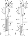
- the device according to the invention shown in the figures comprises a line 10 for conveying, analyzing and sorting objects according to predetermined criteria, this line 10, called the calibration line 10, being provided with selective unloading means (not shown) objects in different accumulation channels 11 which extend generally orthogonal to the line 10 of calibration, with an upstream end portion 12 located under the unloading means of the line 10 of calibration.
- a calibration line 10 is well known in itself (cf. for example in particular EP 0729908 , US 7159373 , US 5230394 , US 5280838 , US 5626238 , US 6234297 ). It generally presents different object analysis stations (weighing, optical analysis, etc.).
- Such a device can comprise any number—for example, from 5 to 50—accumulation channels 11 parallel to each other and which adjoin laterally.
- each accumulation channel 11 is adapted to be able to receive a batch of floating objects intended to fill a single crate or box, at a reception station 16 supplied by the channel 15 for collection. Nevertheless, this is not necessary and it remains possible that each batch of objects contained in an accumulation channel and released in the collection channel 15 be the subject of another treatment at the level of the reception station 16 or several reception stations. Be that as it may, each accumulation channel 11 has a sufficient length to be able to receive all the objects of the same batch, to be the subject of the same subsequent processing. In practice, each accumulation channel 11 receives objects having specific characteristics with respect to the selection criteria, for example a predetermined size when the objects are fruits. In the same batch, all the objects therefore have the same characteristics, in particular the same caliber.
- the accumulation channels 11 are supplied and traversed by a hydraulic current (generally water, possibly with treatment additives) generated by a hydraulic supply device equipped with pumping and recirculation means, as described in its general characteristics, for example by US 7159373 .
- the hydraulic current formed in each accumulation channel 11 is adapted to be able to ensure the transport of floating objects in the hydraulic current, the latter having a free upper surface.
- the hydraulic supply device comprises in particular a supply line 29 extending along all the upstream ends 22 of the accumulation channels 11 receiving the hydraulic flow generated by a recirculation pump 32 itself connected to at least a reception station 16 and a pipe 28 for the recirculation of the hydraulic current in a closed circuit.
- the hydraulic supply device of each accumulation channel 11 comprises a controlled valve, called channel valve 30, at the upstream end 22 of each accumulation channel 11 .
- This channel valve 30 is equipped with a movable member 31 such as a throttle valve making it possible to adjust the flow rate of the hydraulic current supplying the channel 11 of accumulation.
- the movable member 31 is controlled in position and moved by an actuator such as a jack 34 itself connected to an installation control unit 33 as described below.
- the butterfly valve 31 of the channel valve 30 is rotatably mounted about a horizontal axis and is controlled in its pivoting by the actuator 34 by means of a rod.
- the hydraulic current flows in the accumulation channels 11, from their upstream portion 12 extending under the unloading means of the calibration line 10, to their opposite downstream end 13 equipped with a retaining/release device 14 allowing, in a closed position, to retain the objects in the accumulation channel while allowing the hydraulic current to pass, and, in the open position, to release them under the effect of the hydraulic current to transfer them into a collection channel 15 located downstream of all accumulation channels 11.
- This retaining/release device 14 may be formed of a simple movable gate, as described for example by WO 2012056186 .
- Each accumulation channel 11 is generally formed of a profile comprising a longitudinal horizontal bottom 19, and two vertical side walls 23.
- the invention makes it possible to achieve, in each accumulation channel 11, a superposition of objects in several layers in the hydraulic current of the accumulation channel 11, and this in a portion of the accumulation channel, called superposition zone 18, which is located downstream of said upstream portion 12 of the accumulation channel 11.
- This overlap zone 18 must have as long a length as possible compared to the total length of the accumulation channel 11 between its upstream portion 12 and its downstream end 13.
- the bottom 19 of the accumulation channel 11 is, in the overlap zone 18, generally horizontal and the vertical side walls 23 are of uniform height over the entire length of the overlap zone 18 of the channel 11 d 'accumulation.
- the accumulation channel 11 there is nothing to prevent provision for the accumulation channel 11 to have a variable height, preferably increasing downstream, in particular in the superposition zone 18 to facilitate the superposition of objects in this superposition zone 18.
- the total height of the accumulation channel 11 is greater than twice the maximum vertical size of each object so as to be able to receive superimposed objects.
- the total height of the accumulation channel 11 is greater than four times the maximum vertical size of each object, and is adapted to allow the vertical superposition of at least four objects one above the other. in the hydraulic current formed in the accumulation channel 11, preferably with a clearance between the objects forming the lowest layer in the hydraulic current, and the bottom 19, so as to avoid the contact of the objects with the bottom 19 and to allow free flow of hydraulic current in the channel 11 of accumulation.
- the total height of the accumulation channel 11 is, at least in the superposition zone 18, adapted to allow the superposition of objects one above the other in the hydraulic current, depending on the number of layers of objects desired in this zone 18 of superposition, and this with a sufficient clearance maintained between the objects and the bottom 19.
- the height of the hydraulic current formed in the accumulation channel 11 must be sufficient to be able to receive these four layers in the hydraulic current, with a clearance as mentioned above.
- the floating objects such as fruits do not necessarily overlap strictly according to uniform and homogeneous layers, but on the contrary overlap each other more or less partially, some of the objects being pushed down for greater immersion, others possibly being pushed back up and being less immersed.
- each accumulation channel 11 located under the calibration line 10, and immediately downstream of the latter, the height of the accumulation channel 11 must be sufficient to be able to receive a layer of objects, with sufficient clearance with the bottom 19 as shown above. Indeed, in this upstream portion 12, the objects are not superimposed.
- each accumulation channel 11 comprises said upstream portion 12 in which the bottom 19a of the accumulation channel 11 is globally horizontal at a first horizontal level, this upstream portion 12 being extended downstream by said overlap zone 18 in which the bottom 19b of the accumulation channel 11 is globally horizontal but at a second horizontal level lower than the first horizontal level, the bottom 19a of said upstream portion 12 being connected to the bottom 19b of the superposition zone 18 by a vertical wall 39 forming a recess downwards downstream, this vertical wall 39 forming a transverse upstream wall of the zone 18 of superposition.
- the vertical side walls 23 have an upper edge 37 that is also generally horizontal over the entire length of the accumulation channel 11, that is to say along said upstream portion 12 and of the overlap zone 18 .
- each accumulation channel 11 is provided with a carriage, called an accelerator carriage 38, forming a jump 17 with respect to the bottom 19 of the accumulation channel 11, this jump 17 forming a sectional restriction having the effect of locally accelerating the speed of the hydraulic current passing above the jump 17, with respect to the speed of the hydraulic current at said upstream portion 12 for supplying objects and with respect to the speed of the hydraulic current in the superposition zone 18 downstream of the jump 17 and the carriage 38 of the accelerator.
- the jump 17 extends, except for clearances allowing movement of the accelerator carriage 38 along the accumulation channel 11, over the entire width of the accumulation channel 11.
- the inclined face 45 and the horizontal face 50 make it possible to produce the local speed acceleration of the hydraulic current above the horizontal face 50.
- the vertical face 51 has the effect of suddenly directing the hydraulic current downwards downstream of the horizontal face 50 and/or of producing turbulence, which has the effect of promoting the immersion of the objects and their superposition immediately at the downstream jump 17. That said, the shapes of the jump 17 can be different, and in particular optimized to favor these phenomena even more.
- the vertical face 51 can be replaced or supplemented by a curved deflector extending from the downstream edge of the horizontal face 50.
- the projection 17 forms an elevation with respect to the level of the bottom 19b of the zone 18 of superposition to locally accelerate the speed of the hydraulic current in the zone 18 of superposition.
- the projection 17 also forms an elevation relative to the level of the bottom 19a of said upstream portion 12 so as also to locally accelerate the speed of the hydraulic current when the accelerator carriage 38 is at the upstream end of the zone 18 of superposition, immediately downstream of the upstream portion 12.
- the projection 17 is adapted to always be under the free surface of the hydraulic current as it is formed and fed into the accumulation channel 11 at its end 22 upstream, the hydraulic current passing above the jump 17 while accelerating but substantially without itself rising above the jump 17.
- the liquid is discharged from the supply line 29, which extends at a level lower than that of the accumulation channels 11, vertically upwards through each channel valve 30 to open at the upstream end 22 of the accumulation channel 11 which, at this end, may have a bottom that is horizontal or inclined downwards and downstream to form said upstream portion 12 for supplying objects via the line 10 for calibration.
- the height of the hydraulic current in this upstream portion 12 is not necessarily the same as that in the overlap zone 18, and in particular may be lower, for example of the order of 200 mm.
- the entire device is adapted so that the free surface of the hydraulic current remains at least substantially at the same horizontal level all along the accumulation channel 11 (possibly with a slight descent making it possible to promote the flow towards the downstream, this slight descent corresponding to a slight downward and downstream inclination of the bottom 19b of the accumulation channel 11 in the superposition zone 18).
- the projection 17 has the effect of favoring the superimposition of the objects immediately downstream of this projection 17, without however causing untimely collisions of the objects with each other.
- the height of the jump 17 is adapted so that the speed of the hydraulic current locally above the jump 17 and in an acceleration zone extending slightly upstream and downstream of this jump 17, i.e. more important than that of the hydraulic current supplied upstream of the channel 11 of accumulation.
- the acceleration of the speed formed by the jump 17 produces a superposition of the objects and maintains the state of superposition of the objects.
- the height of the jump 17 is in particular determined so as to optimize the superposition of the objects when the speed of the hydraulic current supplied upstream of the accumulation channel 11 corresponds to a superposition speed Vmax.
- Such a jump 17 has the effect of locally accelerating this superposition speed of the hydraulic current by a significant value, typically of the order of 50% or more.
- the height of the hydraulic current formed in the upstream portion 12 of the accumulation channel 11 is for example of the order of 100 mm to 150 mm
- this same hydraulic current has a height of the order of 50 mm to 100 mm - in particular of the order of 80 mm - plumb and above the projection 17.
- the height of the hydraulic current in the zone 18 of superposition is for example between 300 mm and 600 mm, by example of the order of 350 mm.
- the height of the hydraulic current above the jump 17 is of the order of 80 mm, whereas it is of the order of 350 mm in the zone 18 of superposition, when the speed of accumulation of the hydraulic current is of the order of 6 m/min in the superposition zone 18, the local speed is 30 m/min to 40 m/min above the jump 17, ie an increase of more than 500%.
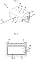
- the accelerator carriage 38 forming the projection 17 is equipped with wheels 52 mounted free to rotate on the accelerator carriage 38 about transverse horizontal axes allowing it to move on the bottom 19b of the zone 18 of superposition between the grid of the device 14 for retaining/ release and the upstream transverse vertical wall 39.
- the accelerator carriage 38 also has an upstream vertical transverse wall 49 extending under the inclined face 45 .
- a traction cable 53 is fixed to the carriage 38, for example to its wall 49 upstream.
- This traction cable 53 extends horizontally upstream as far as the transverse vertical wall 39 at the upstream end of the superposition zone 18, which it crosses by via a watertight crossing 54, to roll up on a drum 55 arranged under the bottom 19a of the upstream portion 12 of the accumulation channel 11, outside the hydraulic current.
- This watertight crossing 54 can be obtained by the fact that the cable 53 is formed of a smooth wire passing through a calibrated orifice of the vertical wall 39, this orifice optionally being provided with a seal.
- This drum 55 is connected to a drive motor 56 by a coupling allowing the drum 55 to be driven in rotation by the motor 56 at least in the direction of winding of the traction cable 53 around the drum 55.
- the motor 56 drive is activated to drive the drum 55 in the direction of the winding of the traction cable 53 around the drum 55, the accelerator carriage 38 is moved upstream in the overlap zone 18 as shown figure 4 .
- the accelerator carriage 38 is advantageously provided with members 60, 61 for brushing the walls of the accumulation channel 11, for example in the form of at least one lower transverse brush 60 arranged to brush the bottom 19 of the zone 18 of overlay and at least one pair of vertical side brushes 61 arranged to brush the side walls 23 of the zone 18 of overlay.
- the drive motor 56 is advantageously equipped with a clutch. When this disengagement is activated, the drum 55 is free to rotate in the direction of the unwinding of the traction cable 53. If the gate of the retaining/release device 14 is raised ( figure 6 ) the accelerator carriage 38 is then driven downstream under the effect of the hydraulic current, pushing the objects into the collection channel 15. The emptying of the accumulation channel 11 is thus greatly accelerated.
- the entire grouping device according to the invention is controlled by a control unit 33 (automaton), generally made up of a computer system, adapted to control the various actuators and motors of the entire installation, in particular the calibration line 10, the unloading means, the devices 14 for retaining/releasing the accumulation channels 11, the reception station 16, the hydraulic supply device and in particular each channel valve 30 and its associated cylinder 34 , engines 56 drive carriages 38 accelerator ...
- This control unit 33 also receives different signals from different sensors or detectors of the device.
- the control unit 33 can be programmed to move the accelerator carriage 38 in the superposition zone 18 according to many different variations depending on the needs of the application and the nature of the objects concerned.
- control unit 33 can be programmed to move the accelerator carriage 38 according to a predetermined movement cycle, for example continuously at a predetermined constant speed or by predetermined successive jumps from the downstream end 13 of the zone 18 of superposition up to the upstream transverse vertical wall 39 of the zone 18 of superposition.
- a predetermined movement cycle for example continuously at a predetermined constant speed or by predetermined successive jumps from the downstream end 13 of the zone 18 of superposition up to the upstream transverse vertical wall 39 of the zone 18 of superposition.
- Each predetermined cycle can be characterized by commands in position and/or in speed and/or in acceleration of the carriage 38 accelerator.
- control unit 33 is programmed to control the movement of the accelerator carriage 38 as a function of signals delivered by at least one detection device such as at least one detection sensor presence and/or at least one camera...
- control unit can be adapted to control the movement of the accelerator carriage 38 according to a servo-control making it possible to optimize the superposition of objects downstream of the accelerator carriage 38 .
- control unit 33 is programmed to control the movement of the accelerator carriage 38 as a function of at least one parameter representative of the quantity of objects delivered into the accumulation channel 11 via the calibration line 10, for example as a function of the number of objects and/or the volume of objects and/or the weight of objects delivered into the accumulation channel 11, such parameters being able to be determined and compared with threshold values predetermined and/or calculated in real time by the control unit 33 of the line 10 for calibration.
- a photoelectric cell 35 is associated with each accumulation channel 11 so as to detect the presence of floating objects in a portion 36 upstream of the superposition zone 18.
- This photoelectric cell 35 is connected to the control unit 33 and adapted to be able to deliver a signal corresponding to the detection or not of objects floating opposite the photoelectric cell 35.
- the photoelectric cell 35 is for example placed at a distance downstream of the transverse vertical wall 39 corresponding to the longitudinal size of the accelerator carriage 38, that is to say immediately downstream of the latter when it is placed against the transverse vertical wall 39 of the zone 18 of superimposition.
- the control unit 33 pilots on the one hand the cylinder 34 controlling the butterfly 31 of the valve 30 of the channel, on the other hand the motor 56 driving the carriage 38 accelerator according to the detection signal delivered by the cell 35 photoelectric.
- the figure 9 represents an example of a control method that can be implemented by the unit 33 for controlling the movements of each carriage 38 accelerator.
- the control unit 33 examines during test step 41 whether the quantity of objects fed into the accumulation channel 11 is sufficient to be able to begin the upstream movement of the carriage 38 accelerator. As indicated above, this determination can be made in different ways.
- the quantity of objects fed into the accumulation channel 11 can be determined by the control unit 33 according to the quantity of objects discharged by the calibration line 10, and the upstream movement of the carriage 38 The accelerator is triggered if this quantity thus determined is greater than a predetermined threshold value (but which may subsequently vary depending on the position of the accelerator carriage 38 in the superposition zone 18).
- control unit 33 examines the state of the signal S delivered by the photoelectric cell 35. As long as this signal S corresponds to an absence of detection of objects (for a sufficient period determined by a time delay) in the field of the photoelectric cell 35, the unit 33 controls (step 42) the actuator 34 so as to maintain the butterfly valve 31 of the channel valve 30 in the minimum flow position, corresponding to a first average speed value of the hydraulic current and in particular to a first relatively low accumulation speed value Vmin of the hydraulic current supplying the channel 11 d 'accumulation.
- This first speed value is adjusted to allow the accumulation of the objects delivered by the calibration line 10, against the retaining/release device 14 in the closed state at the downstream end 13 of the supply channel 11, and to minimize shocks between the retaining/release device 14 and the objects and between them ( picture 3 ).
- the flow delivered by the channel valve 30 in the minimum flow position of the butterfly valve 31 corresponds to an average speed of accumulation of the hydraulic current of the order of 5 to 10 m/min.
- the unit 33 controls (step 43) the motor 56 in the direction of the winding of the drum 55 so as to to cause the movement of the carriage 38 accelerator upstream over a predetermined distance, for example corresponding to the longitudinal size of the carriage 38 accelerator.
- the unit 33 controls (step 44) the cylinder 34 so as to place and maintain the throttle valve 31 of the channel valve 30 in the maximum flow position, corresponding to a second average speed value of the hydraulic current, and in particular at a second superposition speed value Vmax, greater than said first accumulation speed value Vmin, the hydraulic current passing above the jump 17 of the accumulation channel 11.
- This second speed value is adjusted to result in the superposition of floating objects in the hydraulic current one above the other downstream of the jump 17, these objects being pushed downstream by the hydraulic current under the effect of this speed ( figure 4 ) and acceleration produced locally by the jump 17.
- the flow delivered by the channel valve 30 in the maximum flow position of the butterfly valve 31 corresponds to an average speed of superposition of the hydraulic current of the order of 10 to 25 m/min.
- the control unit 33 maintains the accelerator carriage 38 in position and this second superposition speed value for a predetermined duration, then repeats the test step 41. This duration is determined so as to obtain a sufficient superimposition of the objects at the downstream of the jump 17, between the retaining/release device 14 and the jump 17.
- a plurality of such cameras can be distributed along the superposition zone 18, for example along the side walls provided for this purpose with viewing windows.
- the aforementioned steps 41 to 44 can be repeated until the number of objects forming a batch of objects in the superposition zone 18 is reached.
- the length of the overlapping zone 18 is adapted so that this number of objects forming a batch can be entirely contained in the overlapping zone 18 between the accelerator carriage 38 and the device 14 for retaining/releasing.
- the length available to contain the superposed objects between the accelerator carriage 38 and the device 14 for retaining/ release is preferably greater than that strictly necessary to contain the greatest number of objects forming a batch of superimposed objects in the zone 18 of superposition. In this way, it is ensured that the accelerator carriage 38 does not abut against this upstream transverse wall 39.
- the number of objects delivered in the accumulation channel 11 is counted for example at the level of the unloading means of the line 10 of calibration, the latter being suitable for unloading the objects individually. It should be noted that the filling time of each accumulation channel 11 can vary considerably in practice, in particular from less than one minute for majority objects, to several days for minority objects.
- the retaining/release device 14 can be opened, and this if the reception station 16 is ready to receive and process the batch of this channel. 11 accumulation.
- control unit 33 triggers the disengagement of the motor 56, the drum 55 being able to unroll freely, the accelerator carriage 38 then being able to be moved downstream in the zone 18 of superposition under the effect of the hydraulic current.
- the superimposed objects are then driven by the hydraulic current and pushed by the accelerator carriage 38 downstream into the channel 15 for collection.
- each channel 11 of accumulation can be greatly reduced, to the benefit of a much greater compactness of the entire installation.
- the layering occurs much faster.
- the guiding of the accumulation channel 11 is greatly accelerated. This results in a significant improvement in the productivity of the installation.
- the accelerator carriage 38 may be a self-propelled carriage and/or carried at least one photoelectric cell and/or at least one camera connected to the control unit 33, in particular by wireless link.
- throttle valve 31 may be provided, corresponding to several different speed values, both in the accumulation phase and in the superimposition phase.
- the speed of superposition Vmax can initially be relatively low (it should initially be just sufficient to start creating a superposition of objects) and increased as the different successive phases of superposition progress, to take a maximum value at the end of the accumulation of a batch of objects, the superposition of the objects then requiring more energy.
- the unit 33 controls a continuous variation of the position of the throttle valve 31 from the accumulation speed until reaching a sufficient value corresponding to a superposition speed, i.e. i.e. capable of causing a hydraulic superposition of the objects, superposition detected by at least one photoelectric cell and/or at least one camera.
- the calibration line 10 can be replaced by any other selective supply device for the accumulation channels.
- the collection channel 15 and the reception station 16 can be replaced by any other device for processing the batches of objects evacuated downstream of the accumulation channels 11 .
- the drive motor 56 is adapted to drive the drum 55 in rotation in the direction of the unwinding of the traction cable 53.
- the accelerator carriage drive cable can be returned upwards above the accumulation channel, the drum and the drive motor of this drum being placed above of the accumulation channel. This avoids the risk of leakage when passing through the wall.
Description
L'invention concerne un procédé et un dispositif de groupage en lots d'objets flottants, notamment des objets fragiles tels que des fruits ou légumes flottants (pommes, tomates,...) ou autres, avec superposition des objets dans au moins un canal hydraulique d'accumulation des objets par lots.The invention relates to a method and a device for grouping floating objects into batches, in particular fragile objects such as floating fruits or vegetables (apples, tomatoes, etc.) or others, with superposition of the objects in at least one channel hydraulic accumulation of objects in batches.
Dans tout le texte, on désigne par "objet flottant" tout objet présentant une flottaison suffisante dans un courant de liquide pour pouvoir être transporté par ce dernier. En conséquence, cette terminologie couvre non seulement les objets flottants en surface du courant liquide, mais également en particulier les objets situés entre deux eaux.Throughout the text, the term “floating object” designates any object having sufficient buoyancy in a current of liquid to be able to be transported by the latter. Consequently, this terminology covers not only objects floating on the surface of the liquid current, but also in particular objects located between two waters.
Dans les installations de calibrage ou de tri d'objets, tels que des fruits fragiles, présentant des canaux pour le transport hydraulique des objets (permettant notamment d'éviter de les endommager), il est intéressant de pouvoir réduire la longueur totale de chaque canal d'accumulation permettant de regrouper les objets par lots, et donc la surface au sol de l'ensemble de l'installation.In installations for grading or sorting objects, such as fragile fruits, having channels for the hydraulic transport of the objects (in particular making it possible to avoid damaging them), it is advantageous to be able to reduce the total length of each channel. of accumulation making it possible to group the objects by batches, and thus the surface on the ground of the whole of the installation.
Différents dispositifs pour former une superposition d'objets dans de tels canaux hydrauliques ont été proposés.
Néanmoins, un tel dispositif est limité dans ses performances, et on constate en pratique qu'il est souvent difficile d'obtenir une superposition en plus de deux couches.Nevertheless, such a device is limited in its performance, and it is observed in practice that it is often difficult to obtain a superposition in more than two layers.
L'invention vise donc à pallier ces inconvénients. À cet effet, elle vise à proposer un procédé selon la revendication 1 et un dispositif de groupage en lots d'objets flottants fragiles selon la revendication 6 permettant de former une superposition hydraulique plus efficace d'objets dans une zone de superposition de chaque canal d'accumulation, c'est-à-dire en particulier avec un plus grand nombre de couches superposées.The invention therefore aims to overcome these drawbacks. To this end, it aims to propose a method according to claim 1 and a device for grouping fragile floating objects into batches according to claim 6 making it possible to form a more efficient hydraulic superposition of objects in a superposition zone of each channel of accumulation, that is to say in particular with a greater number of superposed layers.
Plus particulièrement, l'invention vise à permettre une telle superposition hydraulique améliorée sans turbulences intempestives, ni détérioration des objets, ni débordement par ailleurs du canal d'accumulation.More particularly, the invention aims to allow such an improved hydraulic superposition without untimely turbulence, nor deterioration of the objects, nor overflowing of the accumulation channel.
L'invention vise également en particulier à permettre une telle superposition hydraulique améliorée sans pertes en rendement de l'installation, et même au contraire en améliorant le rendement de production des lots d'objets.The invention also aims in particular to allow such an improved hydraulic superposition without loss of efficiency of the installation, and even on the contrary by improving the production efficiency of the batches of objects.
L'invention vise également à proposer un tel procédé et un tel dispositif de groupage qui présentent simultanément d'autres avantages, en particulier ne nécessitent qu'un débit réduit de courant hydraulique.The invention also aims to provide such a method and such a grouping device which simultaneously have other advantages, in particular require only a reduced flow rate of hydraulic current.
Dans tout le texte, les termes "amont" et "aval" sont utilisés en référence au sens de circulation des objets dans le dispositif de groupage, correspondant également au sens de circulation du courant hydraulique transportant ces objets.Throughout the text, the terms “upstream” and “downstream” are used with reference to the direction of circulation of the objects in the grouping device, also corresponding to the direction of circulation of the hydraulic current transporting these objects.
L'invention concerne donc un procédé de groupage en lots d'objets flottants -notamment d'objets fragiles tels que des fruits ou légumes flottants- dans au moins un canal, dit canal d'accumulation, dans lequel :
- un courant hydraulique apte à transporter les objets est formé dans chaque canal d'accumulation,
- une portion amont d'au moins un canal d'accumulation est alimentée avec des objets de sorte que les objets sont transportés par le courant hydraulique le long du canal d'accumulation jusqu'à une extrémité aval de ce dernier dotée d'un dispositif de retenue/libération des objets, ce dispositif de retenue/libération étant transparent au courant hydraulique circulant dans le canal d'accumulation,
- chaque canal d'accumulation présentant un fond et des parois latérales et, au moins dans une portion aval de ce dernier, dite zone de superposition, une hauteur supérieure à deux fois l'encombrement vertical maximum de chaque objet de façon à pouvoir recevoir des objets superposés,
- la vitesse du courant hydraulique formé dans chaque canal d'accumulation est accélérée localement par un ressaut vers le haut du fond du canal d'accumulation formant une restriction de section transversale du canal d'accumulation ayant pour effet d'accélérer localement la vitesse du courant hydraulique passant au-dessus de ce ressaut, de façon à entraîner une superposition des objets retenus dans la zone de superposition du canal d'accumulation entre ledit ressaut et le dispositif de retenue/libération fermé pour retenir les objets,
- a hydraulic current capable of transporting the objects is formed in each accumulation channel,
- an upstream portion of at least one accumulation channel is supplied with objects such that the objects are transported by the hydraulic current along the accumulation channel to a downstream end of the latter provided with a device for retention/release of the objects, this retention/release device being transparent to the hydraulic current flowing in the accumulation channel,
- each accumulation channel having a bottom and side walls and, at least in a downstream portion of the latter, known as the superposition zone, a height greater than twice the maximum vertical size of each object so as to be able to receive objects superimposed,
- the velocity of the hydraulic current formed in each accumulation channel is locally accelerated by an upward jump of the bottom of the accumulation channel forming a cross-sectional restriction of the accumulation channel having the effect of locally accelerating the velocity of the current hydraulic system passing above this projection, so as to cause the objects retained to be superposed in the superposition zone of the accumulation channel between the said projection and the retention/release device closed to retain the objects,
L'invention s'étend à un dispositif permettant la mise en oeuvre d'un procédé selon l'invention. Elle s'étend donc également à un dispositif de groupage en lots d'objets flottants -notamment d'objets fragiles tels que des fruits ou légumes flottants- comprenant :
- au moins un canal, dit canal d'accumulation,
- un dispositif d'alimentation hydraulique adapté pour former, dans chaque canal d'accumulation, un courant hydraulique apte à transporter les objets le long du canal d'accumulation,
- un dispositif d'alimentation en objets d'une portion amont de chaque canal d'accumulation,
- chaque canal d'accumulation étant doté, à une extrémité aval de ce dernier, d'un dispositif de retenue/libération des objets qu'il contient, ce dispositif de retenue/libération étant transparent au courant hydraulique circulant dans le canal d'accumulation,
- chaque canal d'accumulation présentant un fond et des parois latérales et, au moins dans une portion aval de ce dernier, dite zone de superposition, une hauteur supérieure à deux fois l'encombrement vertical maximum de chaque objet de façon à pouvoir recevoir des objets superposés,
- chaque canal d'accumulation comprenant un ressaut vers le haut du fond du canal d'accumulation adapté pour former une restriction de section transversale du canal d'accumulation ayant pour effet d'accélérer localement la vitesse du courant hydraulique passant au-dessus de ce ressaut, de façon à entraîner une superposition des objets retenus dans la zone de superposition du canal d'accumulation entre ledit ressaut et le dispositif de retenue/libération fermé pour retenir les objets,
- ledit ressaut de chaque canal d'accumulation est formé par un dispositif mobile dans ladite zone de superposition,
- chaque canal d'accumulation comporte un dispositif motorisé d'entraînement en déplacement dudit dispositif mobile dans ladite zone de superposition depuis l'extrémité aval du canal d'accumulation vers l'amont.
- at least one channel, called the accumulation channel,
- a hydraulic supply device adapted to form, in each accumulation channel, a hydraulic current capable of transporting the objects along the accumulation channel,
- a device for supplying objects to an upstream portion of each accumulation channel,
- each accumulation channel being provided, at a downstream end of the latter, with a device for retaining/releasing the objects it contains, this retaining/release device being transparent to the hydraulic current flowing in the accumulation channel,
- each accumulation channel having a bottom and side walls and, at least in a downstream portion of the latter, called the superposition zone, a height greater than twice the maximum vertical size of each object so as to be able to accommodate superimposed objects,
- each accumulation channel comprising a step upward from the bottom of the accumulation channel adapted to form a cross-sectional restriction of the accumulation channel having the effect of locally accelerating the speed of the hydraulic stream passing above this step , so as to cause a superposition of the objects retained in the superposition zone of the accumulation channel between the said projection and the retention/release device closed to retain the objects,
- said projection of each accumulation channel is formed by a mobile device in said superposition zone,
- each accumulation channel comprises a motorized drive device for moving said mobile device in said overlapping zone from the downstream end of the accumulation channel upstream.
L'invention s'étend également à un procédé mis en oeuvre par un dispositif de groupage selon l'invention.The invention also extends to a method implemented by a grouping device according to the invention.
L'inventeur a constaté avec surprise qu'un tel déplacement d'un ressaut formant localement une restriction de section transversale (ou col) dans la zone de superposition lors d'étape d'accumulation permet d'obtenir une superposition progressive et homogène des objets dans la zone de superposition, et d'obtenir une superposition des objets en un nombre de couches plus important. Il s'avère en effet que l'effet de superposition produit par cette restriction de section transversale est beaucoup plus important immédiatement à l'aval de cette restriction de section transversale. En conséquence, le déplacement de cette restriction de section transversale vers l'amont du courant hydraulique permet d'arranger les objets en couches superposées progressivement depuis l'extrémité aval de la zone de superposition, vers l'amont au fur et à mesure de l'alimentation des objets dans la zone de superposition en bénéficiant pour chaque objet alimenté dans la zone de superposition de l'effet maximal de superposition produit par cette restriction de section transversale. On réalise ainsi une superposition progressive pouvant être qualifiée de « superposition hydraulique dynamique ».The inventor has observed with surprise that such a displacement of a projection locally forming a restriction of cross-section (or neck) in the superposition zone during the accumulation step makes it possible to obtain a progressive and homogeneous superposition of the objects. in the superposition zone, and to obtain a superposition of the objects in a greater number of layers. It turns out that the superposition effect produced by this cross-section restriction is much greater immediately downstream of this cross-section restriction. Consequently, the displacement of this cross-sectional restriction towards the upstream of the hydraulic current makes it possible to arrange the objects in progressively superimposed layers from the downstream end of the superposition zone, towards the upstream as the flow progresses. feeding of objects in the overlapping zone while benefiting for each object fed into the overlapping zone from the maximum effect of overlapping produced by this restriction of cross section. A progressive superposition is thus produced which can be qualified as “dynamic hydraulic superposition”.
En outre, cette superposition hydraulique dynamique est obtenue continûment, sans choc des objets les uns contre les autres ou contre des organes mécaniques mobiles, c'est-à-dire sans risque de détérioration des objets eux-mêmes, même lorsque ces derniers sont extrêmement fragiles.In addition, this dynamic hydraulic superposition is obtained continuously, without impact of the objects against each other or against moving mechanical components, that is to say without risk of deterioration of the objects themselves, even when the latter are extremely fragile.
On constate en pratique avec une telle superposition hydraulique dynamique que les objets peuvent être superposés en un nombre de couches supérieur à 2, typiquement de l'ordre de 3 à 4 avec des fruits ou légumes flottants tels que des pommes, ce qui permet de réduire encore de moitié la longueur des canaux d'accumulation par rapport à un dispositif de superposition hydraulique connu susmentionné.It is observed in practice with such a dynamic hydraulic superposition that the objects can be superimposed in a number of layers greater than 2, typically of the order of 3 to 4 with floating fruits or vegetables such as apples, which makes it possible to reduce still half the length of the accumulation channels compared to a known hydraulic stacking device mentioned above.
Il est à noter à ce titre que le nombre maximum de couches de superposition pouvant être obtenu avec des objets flottants est limité par la densité relative des objets par rapport au courant hydraulique. L'invention permet de superposer les objets en un nombre de couches correspondant à ce nombre maximum.It should be noted in this respect that the maximum number of superposition layers that can be obtained with floating objects is limited by the relative density of the objects with respect to the hydraulic current. The invention makes it possible to superimpose the objects in a number of layers corresponding to this maximum number.
Par exemple, si les canaux d'accumulation d'un dispositif antérieur sans superposition des objets doivent présenter une longueur de l'ordre de 12 m, les canaux d'accumulation peuvent présenter une longueur de l'ordre de 6 m avec une superposition hydraulique des objets conforme à
Ainsi, en particulier, dans certains modes de réalisation d'un procédé de groupage et d'un dispositif de groupage selon l'invention la hauteur du canal d'accumulation dans la zone de superposition est choisie en fonction du nombre de couches d'objets superposés dans la zone de superposition et de la dimension maximum de chaque objet. Ainsi, la hauteur du canal d'accumulation dans la zone de superposition est supérieure à deux fois l'encombrement vertical maximum de chaque objet. Dans le cas de fruits ou légumes tels que des pommes, la hauteur du canal d'accumulation dans la zone de superposition est avantageusement comprise entre trois et quatre fois l'encombrement vertical maximum de chaque objet. D'autres valeurs sont possibles.Thus, in particular, in certain embodiments of a grouping method and of a grouping device according to the invention, the height of the accumulation channel in the superposition zone is chosen according to the number of layers of objects overlapped in the overlap area and the maximum dimension of each object. Thus, the height of the accumulation channel in the superposition zone is greater than twice the maximum vertical bulk of each object. In the case of fruits or vegetables such as apples, the height of the accumulation channel in the superposition zone is advantageously between three and four times the maximum vertical bulk of each object. Other values are possible.
Le dispositif d'alimentation hydraulique est adapté pour pouvoir former dans chaque canal d'accumulation un courant hydraulique présentant au moins localement au-dessus dudit ressaut une vitesse apte à entraîner une superposition des objets retenus dans la zone de superposition du canal d'accumulation, à l'aval du ressaut contre le dispositif de retenue/libération fermé de façon à retenir les objets. Le ressaut et son déplacement dans la zone de superposition peuvent faire l'objet de très nombreuses variantes de réalisation.The hydraulic supply device is adapted to be able to form in each accumulation channel a hydraulic current having, at least locally above said projection, a speed capable of causing a superposition of the objects retained in the superposition zone of the accumulation channel, downstream of the jump against the retaining/release device closed so as to retain the objects. The jump and its displacement in the superposition zone can be the subject of very many variant embodiments.
Pour obtenir une accélération locale de la vitesse du courant hydraulique et une superposition des objets à l'aval immédiat du ressaut, il suffit en effet que la restriction de section transversale formée par le ressaut réduise localement la section de passage du courant hydraulique à partir du fond et des parois latérales du canal d'accumulation.To obtain a local acceleration of the speed of the hydraulic current and a superposition of the objects immediately downstream of the jump, it is in fact sufficient for the cross-sectional restriction formed by the jump to locally reduce the passage section of the hydraulic current from the bottom and side walls of the accumulation channel.
La restriction de section transversale formée par ledit ressaut réduit localement la hauteur de passage du courant hydraulique. Il est possible dans certains modes de réalisation de prévoir que cette restriction de section transversale réduise également localement la largeur de passage du courant hydraulique. Néanmoins, cela n'est en général pas nécessaire, de sorte que dans certains modes de réalisation préférentiels, la restriction de section transversale formée par le ressaut est uniquement une restriction de section verticale, la largeur de passage du courant hydraulique ménagée par le canal d'accumulation au-dessus du ressaut n'étant pas réduite.The restriction in cross-section formed by said projection locally reduces the passage height of the hydraulic current. It is possible in certain embodiments to provide that this cross-sectional restriction also locally reduces the passage width of the hydraulic current. Nevertheless, this is generally not necessary, so that in certain preferred embodiments, the cross-sectional restriction formed by the projection is only a vertical sectional restriction, the passage width of the hydraulic current provided by the channel d accumulation above the jump not being reduced.
Ledit ressaut forme partiellement barrage à l'écoulement du courant hydraulique, ce dernier s'accélérant en passant au-dessus du ressaut pour s'écouler vers l'aval. Ainsi, le ressaut et ladite restriction de section transversale ainsi formée s'étendent toujours sous la surface libre du courant hydraulique et à distance de cette surface libre en ménageant, entre ce ressaut et la surface libre du courant hydraulique, une section de passage du courant hydraulique dans laquelle la vitesse du courant hydraulique est accélérée localement.Said jump partially forms a barrier to the flow of the hydraulic current, the latter accelerating as it passes above the jump to flow downstream. Thus, the projection and said cross-sectional restriction thus formed always extend below the free surface of the hydraulic current and at a distance from this free surface by providing, between this projection and the free surface of the hydraulic current, a passage section of the current hydraulic in which the speed of the hydraulic current is locally accelerated.
Dans certains modes de réalisation préférentiels, la hauteur du ressaut par rapport au fond du canal d'accumulation est inférieure ou égale à la hauteur totale du courant hydraulique alimenté dans le canal d'accumulation, de sorte que ce dernier ne s'élève sensiblement pas au-dessus du ressaut, seule sa vitesse étant augmentée localement.In certain preferred embodiments, the height of the jump relative to the bottom of the accumulation channel is less than or equal to the total height of the hydraulic current fed into the accumulation channel, so that the latter does not rise substantially above the jump, only its speed being increased locally.
Dans un procédé et un dispositif selon l'invention, le ressaut forme une restriction de section transversale uniquement localement dans la zone de superposition, c'est-à-dire que la longueur du ressaut (et donc de ladite restriction de section transversale, c'est-à-dire de la zone dans laquelle la vitesse du courant hydraulique est accélérée) est aussi faible que possible de façon à limiter la longueur perdue de la zone de superposition due à la présence du ressaut. Ainsi, la longueur du ressaut est inférieure à la longueur de la zone de superposition, notamment inférieure à la moitié de la longueur de la zone de superposition, en particulier inférieure au quart de la longueur de la zone de superposition, plus particulièrement inférieure au dixième de la longueur de la zone de superposition. Par exemple, typiquement, la longueur du ressaut (et donc de ladite restriction de section transversale, c'est-à-dire de la zone dans laquelle la vitesse du courant hydraulique est accélérée) est inférieure à 1 m, en particulier inférieure à 50 cm, plus particulièrement inférieure à 30 cm, par exemple de l'ordre de 10 cm à 25 cm.In a method and a device according to the invention, the projection forms a cross-sectional restriction only locally in the overlap zone, that is to say that the length of the projection (and therefore of said cross-sectional restriction, c that is to say of the zone in which the speed of the hydraulic current is accelerated) is as low as possible so as to limit the lost length of the superposition zone due to the presence of the jump. Thus, the length of the jump is less than the length of the superposition zone, in particular less than half the length of the superposition zone, in particular less than a quarter of the length of the superposition zone, more particularly less than a tenth the length of the overlap region. For example, typically, the length of the jump (and therefore of said cross-sectional restriction, that is to say of the zone in which the speed of the hydraulic current is accelerated) is less than 1 m, in particular less than 50 cm, more particularly less than 30 cm, for example of the order of 10 cm to 25 cm.
En particulier, dans certains modes de réalisation possibles de l'invention ledit ressaut comprend un pan amont incliné vers le haut vers l'aval.In particular, in certain possible embodiments of the invention, said projection comprises an upstream slope inclined upwards downstream.
D'autres formes de réalisation sont possibles, notamment avec une (ou plusieurs) portion(s) présentant une section longitudinale verticale courbe favorisant, à la façon d'un déflecteur courbe, l'accélération locale du courant hydraulique et/ou son orientation vers le bas à l'aval du ressaut et/ou les turbulences à l'aval du ressaut, phénomènes qui peuvent améliorer l'effet d'immersion et de superposition des objets à l'aval du ressaut.Other embodiments are possible, in particular with one (or more) portion(s) having a curved vertical longitudinal section favoring, like a curved deflector, the local acceleration of the hydraulic current and/or its orientation towards the bottom downstream of the jump and/or the turbulence downstream of the jump, phenomena which can improve the effect of immersion and superposition of objects downstream of the jump.
Le déplacement du ressaut dans la zone de superposition le long du canal d'accumulation peut être obtenu de diverses manières. Par exemple, le ressaut peut être formé par au moins une plaque s'étendant au moins horizontalement transversalement dans le courant hydraulique dans le canal d'accumulation, cette plaque étant guidée en translation le long du canal d'accumulation.The displacement of the jump in the superposition zone along the accumulation channel can be obtained in various ways. For example, the jump can be formed by at least one plate extending at least horizontally transversely into the hydraulic flow in the channel accumulation, this plate being guided in translation along the accumulation channel.
Dans certains modes de réalisation conformes à l'invention particulièrement avantageux le ressaut est formé par un chariot déplacé dans le courant hydraulique dans la zone de superposition.In certain particularly advantageous embodiments in accordance with the invention, the jump is formed by a carriage moved in the hydraulic current in the superposition zone.
Ainsi, un procédé de groupage selon ces modes de réalisation de l'invention est aussi caractérisé en ce que lors d'une étape d'accumulation d'objets dans un canal d'accumulation, un chariot, dit chariot accélérateur, formant ledit ressaut est déplacé -notamment par un dispositif motorisé d'entraînement- sur le fond du canal d'accumulation dans ladite zone de superposition dans le courant hydraulique depuis l'extrémité aval du canal d'accumulation vers l'amont au fur et à mesure de l'alimentation des objets de façon à entraîner la superposition des objets en plusieurs couches dans la zone de superposition entre ledit chariot accélérateur et le dispositif de retenue/libération fermé pour retenir les objets.Thus, a grouping method according to these embodiments of the invention is also characterized in that during a step of accumulating objects in an accumulation channel, a carriage, called an accelerator carriage, forming said jump is moved - in particular by a motorized drive device - on the bottom of the accumulation channel in said superposition zone in the hydraulic current from the downstream end of the accumulation channel upstream as the feeding of the objects so as to cause the superposition of the objects in several layers in the superposition zone between said accelerator carriage and the retaining/release device closed to retain the objects.
De même, un dispositif de groupage selon ces modes de réalisation de l'invention est aussi caractérisé en ce que ledit ressaut de chaque canal d'accumulation est formé par un chariot, dit chariot accélérateur, mobile le long de ladite zone de superposition, et en ce que ledit dispositif motorisé d'entraînement est adapté pour pouvoir entraîner ledit chariot accélérateur en déplacement sur le fond du canal d'accumulation dans ladite zone de superposition vers l'amont depuis l'extrémité aval du canal d'accumulation. Ainsi, ledit au moins un dispositif mobile est formé par un chariot accélérateur adapté pour pouvoir se déplacer en translation dans et le long de la zone de superposition. Avantageusement et selon l'invention ledit chariot accélérateur est guidé en translation dans la zone de superposition par au moins une partie des parois (parois latérales et/ou fond) du canal d'accumulation.Similarly, a grouping device according to these embodiments of the invention is also characterized in that said projection of each accumulation channel is formed by a carriage, called an accelerator carriage, movable along said overlapping zone, and in that said motorized drive device is adapted to be able to drive said accelerator carriage in displacement on the bottom of the accumulation channel in said overlapping zone towards the upstream from the downstream end of the accumulation channel. Thus, said at least one mobile device is formed by an accelerator carriage adapted to be able to move in translation in and along the superposition zone. Advantageously and according to the invention, said accelerator carriage is guided in translation in the superposition zone by at least part of the walls (side walls and/or bottom) of the accumulation channel.
En outre, le ressaut -notamment tel que formé par le chariot accélérateur- s'étend de préférence, aux jeux près permettant le déplacement du chariot accélérateur le long du canal d'accumulation, sur toute la largeur du canal d'accumulation et à partir du fond du canal d'accumulation. En variante, rien n'empêche de prévoir au moins une section de passage du courant hydraulique entre le fond et le ressaut et/ou au moins une section de passage du courant hydraulique entre le ressaut et au moins une paroi latérale du canal d'accumulation.In addition, the projection - in particular as formed by the accelerator carriage - preferably extends, except for clearances allowing the displacement of the accelerator carriage along the accumulation channel, over the entire width of the accumulation channel and from from the bottom of the accumulation channel. As a variant, there is nothing to prevent providing at least one passage section for the hydraulic current between the bottom and the jump and/or at least one passage section of the hydraulic current between the jump and at least one side wall of the accumulation channel.
Ainsi, selon une variante possible de l'invention, le chariot accélérateur peut être guidé en translation dans le canal d'accumulation uniquement du fait qu'il présente une densité proche de celle du courant hydraulique, de sorte qu'il reste entre deux eaux dans le courant hydraulique et est guidé par les parois (parois latérales et/ou fond) du canal d'accumulation dans la zone de superposition.Thus, according to a possible variant of the invention, the accelerator carriage can be guided in translation in the accumulation channel only because it has a density close to that of the hydraulic current, so that it remains between two waters. in the hydraulic flow and is guided by the walls (side walls and/or bottom) of the accumulation channel into the overlap zone.
Cela étant, dans certains modes de réalisation possibles de l'invention, le chariot est guidé en translation dans le canal d'accumulation par un dispositif de guidage. Tout dispositif de guidage peut être envisagé pour guider le ressaut -notamment le chariot accélérateur- en translation le long du canal d'accumulation dans la zone de superposition. Par exemple, ce dispositif de guidage peut être choisi parmi les dispositifs à organes de roulement le long d'au moins une paroi formant le canal d'accumulation (parois latérales et/ou fond) ; les dispositifs à rail(s) et galet(s) ; les dispositifs à coulisseau(x) dans au moins une glissière ; les dispositifs à patins glissant le long d'au moins une paroi formant le canal d'accumulation (parois latérales et/ou fond) ; et leurs combinaisons. Ce ressaut est guidé dans le courant hydraulique ou au-dessus du courant hydraulique et/ou sur le côté du canal d'accumulation, et est entraîné par un dispositif motorisé tel qu'un moteur ou un actionneur entraînant une vis sans fin ou un tambour d'enroulement d'un câble ou autre.This being the case, in certain possible embodiments of the invention, the carriage is guided in translation in the accumulation channel by a guiding device. Any guiding device can be envisaged to guide the jump—in particular the accelerator carriage—in translation along the accumulation channel in the superposition zone. For example, this guide device can be chosen from devices with running gear along at least one wall forming the accumulation channel (side walls and/or bottom); rail(s) and roller(s) devices; devices with slide(s) in at least one slide; devices with pads sliding along at least one wall forming the accumulation channel (side walls and/or bottom); and their combinations. This jump is guided in the hydraulic current or above the hydraulic current and/or on the side of the accumulation channel, and is driven by a motorized device such as a motor or an actuator driving a worm screw or a drum winding of a cable or other.
En particulier, dans certains modes de réalisation possibles de l'invention ledit chariot accélérateur est doté d'organes de roulement sur le fond du canal d'accumulation. En variante ou en combinaison le chariot accélérateur peut être doté d'organes de roulement sur au moins l'une des parois latérales du canal d'accumulation. Ces organes de roulement peuvent être choisis notamment parmi les roues, les rouleaux, les galets.In particular, in certain possible embodiments of the invention, said accelerator carriage is provided with rolling members on the bottom of the accumulation channel. As a variant or in combination, the accelerator carriage can be provided with running gear on at least one of the side walls of the accumulation channel. These rolling members can be chosen in particular from wheels, rollers, rollers.
En outre, dans certains modes de réalisation avantageux de l'invention, ledit chariot accélérateur est doté d'organes de brossage d'au moins une partie des parois du canal d'accumulation. Il peut s'agir en particulier d'organes de brossage au moins du fond du canal d'accumulation. De préférence, le chariot accélérateur est doté d'organes de brossage du fond et/ou des parois latérales du canal d'accumulation sur au moins une partie de leur hauteur. De la sorte, le déplacement du chariot dans le canal d'accumulation a également pour effet et avantage de nettoyer le canal d'accumulation, permettant ainsi de s'affranchir de phases de nettoyage spécifiques.Furthermore, in certain advantageous embodiments of the invention, said accelerator carriage is provided with members for brushing at least part of the walls of the accumulation channel. They may in particular be members for brushing at least the bottom of the accumulation channel. Preferably, the cart accelerator is provided with members for brushing the bottom and/or the side walls of the accumulation channel over at least part of their height. In this way, the movement of the carriage in the accumulation channel also has the effect and advantage of cleaning the accumulation channel, thus making it possible to dispense with specific cleaning phases.
Par ailleurs, le ressaut peut être entraîné en déplacement par rapport au canal d'accumulation par tout dispositif motorisé d'entraînement approprié, notamment pouvant être choisi parmi au moins un moteur embarqué à bord du dit chariot accélérateur (ce dernier étant alors de type automobile, alimenté en énergie et/ou commandé dans ses déplacements par une liaison sans fil ou au contraire par une liaison filaire) ; au moins un moteur fixé au bâti du canal d'accumulation et agencé pour entraîner au moins un organe menant (câble(s), dispositif à vis sans fin et écrou (vis à billes)...) relié au ressaut. Dans tout le texte, sauf indication contraire, le terme « moteur » et ses dérivés désignent tout dispositif permettant de transformer une énergie quelconque non mécanique en énergie mécanique, et couvrent donc en particulier aussi bien les moteurs rotatifs tels que les moteurs électriques, que les actionneurs tels que les vérins pneumatiques et/ou hydrauliques ou autre.Furthermore, the jump can be driven in displacement relative to the accumulation channel by any suitable motorized drive device, in particular being able to be chosen from at least one motor on board said accelerator carriage (the latter then being of the automotive type , supplied with energy and/or controlled in its movements by a wireless link or on the contrary by a wired link); at least one motor fixed to the frame of the accumulation channel and arranged to drive at least one driving member (cable(s), worm screw device and nut (ball screw)...) connected to the projection. Throughout the text, unless otherwise indicated, the term "motor" and its derivatives designates any device making it possible to transform any non-mechanical energy into mechanical energy, and therefore covers in particular both rotary motors such as electric motors and actuators such as pneumatic and/or hydraulic cylinders or the like.
Dans certains modes de réalisation possibles selon l'invention ledit dispositif motorisé d'entraînement comprend :
- au moins un câble relié audit chariot accélérateur, s'étendant vers l'amont du chariot accélérateur,
- un dispositif motorisé de traction d'au moins un tel câble vers l'amont.
- at least one cable connected to said accelerator carriage, extending upstream of the accelerator carriage,
- a motorized device for pulling at least one such cable upstream.
Par exemple, ce dispositif motorisé de traction peut comporter :
- un tambour d'enroulement d'un câble, ce tambour étant monté rotatif autour d'un axe de rotation fixe par rapport à un bâti du canal d'accumulation,
- un moteur accouplé au tambour de façon à pouvoir l'entraîner en rotation au moins dans le sens de l'enroulement du câble sur le tambour.
- a drum for winding a cable, this drum being rotatably mounted around an axis of rotation fixed with respect to a frame of the accumulation channel,
- a motor coupled to the drum so as to be able to drive it in rotation at least in the direction of the winding of the cable on the drum.
Le contrôle du déplacement du ressaut lors de chaque étape d'accumulation peut faire l'objet de différentes variantes.The control of the displacement of the jump during each accumulation step can be the subject of different variants.
Selon une première variante possible, ce déplacement est commandé à une vitesse de déplacement fixe du ressaut vers l'amont, cette vitesse pouvant être ajustable par l'utilisateur de façon à permettre un réglage initial de l'installation en fonction des objets à traiter. Ainsi, dans cette première variante, l'utilisateur procède à un réglage initial en ajustant la vitesse de déplacement du ressaut -notamment du chariot accélérateur- afin d'optimiser la superposition des objets dans la zone de superposition.According to a first possible variant, this movement is controlled at a fixed speed of movement of the jump upstream, this speed being able to be adjusted by the user so as to allow an initial adjustment of the installation according to the objects to be treated. Thus, in this first variant, the user carries out an initial adjustment by adjusting the speed of movement of the jump—in particular of the accelerator carriage—in order to optimize the superposition of the objects in the superposition zone.
Selon une deuxième variante possible, le déplacement du ressaut est contrôlé de façon entièrement automatique sur commande d'une unité de commande telle qu'un dispositif informatique programmé à cet effet.According to a second possible variant, the displacement of the jump is controlled entirely automatically on command from a control unit such as a computer device programmed for this purpose.
En particulier, dans certains modes de réalisation de l'invention lors d'une étape d'accumulation d'objets dans un canal d'accumulation :
- ledit ressaut est maintenu fixe dans le canal d'accumulation tant qu'une quantité d'objets alimentés dans le canal d'accumulation n'est pas atteinte,
- ledit ressaut est déplacé vers l'amont dans le canal d'accumulation lorsque ladite quantité d'objets alimentés dans le canal d'accumulation est atteinte.
- said jump is maintained fixed in the accumulation channel as long as a quantity of objects fed into the accumulation channel is not reached,
- said jump is moved upstream in the accumulation channel when said quantity of objects fed into the accumulation channel is reached.
Il est à noter que cette quantité d'objets alimentés dans le canal d'accumulation peut être évaluée, détectée ou déterminée de différentes manières, et qu'elle n'est pas nécessairement constituée d'une valeur fixe, mais au contraire qui peut être variable en fonction par exemple du temps et/ou de la position du ressaut dans la zone de superposition.It should be noted that this quantity of objects fed into the accumulation channel can be evaluated, detected or determined in different ways, and that it is not necessarily made up of a fixed value, but on the contrary which can be variable as a function, for example, of the time and/or of the position of the jump in the superposition zone.
Ainsi, l'unité de commande peut être adaptée pour contrôler le déplacement du ressaut -notamment du chariot accélérateur- vers l'amont :
- en fonction de la quantité d'objets alimentée dans ladite portion amont du canal d'accumulation (cette quantité pouvant être enregistrée ou déterminée par l'unité de commande, notamment lorsque cette dernière commande également le déchargement sélectif des objets dans les canaux d'accumulation) ;
- en fonction des objets présents immédiatement à l'amont du ressaut et/ou des objets superposés immédiatement à l'aval du ressaut, la détection de ces objets pouvant être réalisée par des capteurs de présence et/ou des dispositifs d'imagerie (caméras) associés à un traitement d'images ;
- si une superposition suffisante des objets est détectée à l'aval du ressaut, de préférence également si la présence d'objets est détectée immédiatement à l'amont du ressaut.
- as a function of the quantity of objects fed into said upstream portion of the accumulation channel (this quantity possibly being recorded or determined by the control unit, in particular when the latter also controls the selective unloading of objects in the accumulation channels );
- depending on the objects present immediately upstream of the jump and/or the superimposed objects immediately downstream of the jump, the detection of these objects being able to be carried out by presence sensors and/or imaging devices (cameras) associated with image processing;
- if a sufficient superimposition of the objects is detected downstream of the jump, preferably also if the presence of objects is detected immediately upstream of the jump.
En particulier, selon une variante possible de l'invention, lors d'une étape d'accumulation d'objets dans un canal d'accumulation :
- la présence d'objets dans une zone amont de chaque canal d'accumulation est détectée,
- sur détection de la présence d'objets dans ladite zone amont, ledit ressaut -notamment ledit chariot accélérateur- est déplacé vers l'amont,
- en l'absence de détection d'objets dans ladite zone amont, ledit ressaut -notamment ledit chariot accélérateur- est maintenu fixe dans le canal d'accumulation.
- the presence of objects in an upstream zone of each accumulation channel is detected,
- on detection of the presence of objects in said upstream zone, said jump - in particular said accelerator carriage - is moved upstream,
- in the absence of detection of objects in said upstream zone, said jump—in particular said accelerator carriage—is kept stationary in the accumulation channel.
Ainsi, un dispositif selon cette variante de l'invention comprend au moins un capteur de présence d'objets dans une zone amont de chaque canal d'accumulation, chaque capteur de présence étant relié à une unité de commande adaptée pour commander ledit dispositif motorisé d'entraînement de façon à :
- déplacer vers l'amont ledit ressaut -notamment ledit chariot accélérateur- sur détection de la présence d'objets dans ladite zone amont,
- maintenir ladite restriction de section transversale -notamment ledit chariot accélérateur- fixe dans le canal d'accumulation en l'absence de détection d'objets dans ladite zone amont. Plus particulièrement, dans certains modes de réalisation avantageux, ledit capteur de présence est disposé dans une portion amont de ladite zone de superposition, de préférence dans la moitié amont, en particulier aux 3/4 amont de ladite zone de superposition.
- moving said jump - in particular said accelerator carriage - upstream upon detection of the presence of objects in said upstream zone,
- maintaining said cross-sectional restriction—in particular said accelerator carriage—fixed in the accumulation channel in the absence of detection of objects in said upstream zone. More particularly, in certain advantageous embodiments, said presence sensor is arranged in an upstream portion of said overlapping zone, preferably in the upstream half, in particular 3/4 upstream of said overlapping zone.
Après déplacement dudit ressaut dans la zone de superposition lors d'une étape d'accumulation, le ressaut est replacé vers l'extrémité aval du canal d'accumulation après vidage de ce dernier, ce replacement pouvant être effectué vers l'aval soit selon le même trajet que celui vers l'amont lors de l'étape d'accumulation mais en sens inverse, soit selon un autre trajet, par exemple en extrayant le ressaut hors du courant hydraulique vers le haut.After displacement of said jump in the superposition zone during an accumulation step, the jump is replaced towards the downstream end of the accumulation channel after emptying of the latter, this replacement being able to be carried out downstream either according to the same route as that upstream during the stage accumulation but in the opposite direction, or according to another path, for example by extracting the jump out of the hydraulic current upwards.
Cela étant, dans certains modes de réalisation préférentiels de l'invention, le déplacement vers l'aval du ressaut -notamment dudit chariot accélérateur- est réalisé en maintenant le ressaut dans le courant hydraulique et au contact des objets, de façon à repousser les objets vers l'aval. Ainsi, lors d'une étape de vidage d'un canal d'accumulation, le dispositif de retenue/libération est ouvert de façon à permettre l'évacuation des objets entraînés par le courant hydraulique hors du canal d'accumulation, et ledit ressaut -notamment ledit chariot accélérateur- est déplacé dans ladite zone de superposition vers l'extrémité aval du canal d'accumulation en repoussant les objets hors du canal d'accumulation. En outre, avantageusement lors d'une étape de vidage ledit ressaut -notamment ledit chariot accélérateur- est déplacé vers l'extrémité aval du canal d'accumulation sous l'effet du courant hydraulique -notamment exclusivement sous l'effet du courant hydraulique-.This being the case, in certain preferred embodiments of the invention, the downstream movement of the jump - in particular of said accelerator carriage - is carried out by maintaining the jump in the hydraulic current and in contact with the objects, so as to repel the objects. downstream. Thus, during a step of emptying an accumulation channel, the retaining/release device is opened so as to allow the evacuation of the objects driven by the hydraulic current out of the accumulation channel, and said jump - in particular said accelerator carriage is moved in said superposition zone towards the downstream end of the accumulation channel by pushing the objects out of the accumulation channel. In addition, advantageously during an emptying step, said jump—in particular said accelerator carriage—is moved towards the downstream end of the accumulation channel under the effect of the hydraulic current—in particular exclusively under the effect of the hydraulic current—.
Ainsi, dans un dispositif de groupage selon ces modes de réalisation de l'invention ledit dispositif motorisé d'entraînement est adapté pour permettre un déplacement dudit dispositif mobile -notamment dudit chariot accélérateur- dans ladite zone de superposition vers l'extrémité aval du canal d'accumulation. Lors de ce déplacement vers l'aval, ledit dispositif mobile - notamment ledit chariot accélérateur- repousse les objets hors du canal d'accumulation, le dispositif de retenue/libération étant ouvert. En outre, avantageusement le dispositif de groupage selon ces modes de réalisation de l'invention est aussi caractérisé en ce que chaque dispositif mobile -notamment ledit chariot accélérateur- est adapté pour pouvoir être entraîné vers l'aval sous l'effet - notamment exclusivement sous l'effet- du courant hydraulique circulant dans le canal d'accumulation et en ce que ledit dispositif motorisé d'entraînement comprend un dispositif de débrayage apte, en position débrayée, à laisser chaque dispositif mobile -notamment ledit chariot accélérateur- libre en déplacement vers l'aval dans le canal d'accumulation. En variante, rien n'empêche de prévoir que ledit dispositif motorisé d'entraînement soit adapté pour pouvoir entraîner chaque dispositif mobile -notamment le chariot accélérateur- en déplacement vers l'aval.Thus, in a grouping device according to these embodiments of the invention, said motorized drive device is adapted to allow movement of said mobile device -in particular said accelerator carriage- in said overlapping zone towards the downstream end of the channel of 'accumulation. During this downstream movement, said mobile device - in particular said accelerator carriage - pushes the objects out of the accumulation channel, the retaining/release device being open. In addition, advantageously the grouping device according to these embodiments of the invention is also characterized in that each mobile device - in particular said accelerator carriage - is adapted to be able to be driven downstream under the effect - in particular exclusively under the effect- of the hydraulic current flowing in the accumulation channel and in that said motorized drive device comprises a disengagement device capable, in the disengaged position, of leaving each mobile device -in particular said accelerator carriage- free to move towards downstream in the accumulation channel. Alternatively, nothing prevents providing that said device motorized drive is adapted to be able to drive each mobile device -in particular the accelerator carriage- moving downstream.
Dans un procédé et un dispositif de groupage selon l'invention, la vitesse d'alimentation du courant hydraulique à l'amont de chaque canal d'accumulation est aussi ajustée pour permettre, compte tenu de l'accélération locale générée par le ressaut, une superposition optimale des objets à l'aval du ressaut.In a grouping method and device according to the invention, the supply speed of the hydraulic current upstream of each accumulation channel is also adjusted to allow, taking into account the local acceleration generated by the jump, a optimal superimposition of objects downstream of the jump.
L'ajustement de la vitesse du courant hydraulique pour entraîner cette superposition des objets peut faire l'objet de différentes variantes. Il est possible par exemple de maintenir la vitesse du courant hydraulique en permanence à une valeur constante et unique susceptible d'entraîner une superposition des objets. Il est aussi possible de compter les objets (ou le poids total des objets) introduits dans chaque canal d'accumulation, et d'ajuster la vitesse du courant hydraulique à une valeur susceptible d'entraîner une superposition des objets dans un canal d'accumulation après avoir alimenté ce canal d'accumulation avec un nombre (ou un poids) minimum prédéterminé d'objets. Il est également possible de détecter (par exemple avec des cellules photoélectriques) la hauteur occupée par les objets dans le canal d'accumulation en un ou plusieurs points le long de ce dernier et d'ajuster la vitesse du courant hydraulique à une valeur susceptible d'entraîner une superposition des objets lorsque cette hauteur correspond à une couche d'objets. L'ajustement des différentes vitesses du courant hydraulique peut être fait de façon discrète, c'est-à-dire en sélectionnant une valeur de vitesse parmi une pluralité de valeurs prédéterminées ; ou au contraire de façon continue en augmentant continûment la vitesse du courant hydraulique jusqu'à ce qu'elle atteigne une valeur à partir de laquelle une superposition des objets est détectée en au moins une zone prédéterminée du canal d'accumulation.The adjustment of the speed of the hydraulic current to cause this superposition of the objects can be the subject of different variants. It is possible, for example, to maintain the speed of the hydraulic current permanently at a constant and unique value likely to cause the objects to overlap. It is also possible to count the objects (or the total weight of the objects) introduced into each accumulation channel, and to adjust the speed of the hydraulic current to a value likely to cause the objects to overlap in an accumulation channel. after having fed this accumulation channel with a predetermined minimum number (or weight) of objects. It is also possible to detect (for example with photoelectric cells) the height occupied by the objects in the accumulation channel at one or more points along the latter and to adjust the speed of the hydraulic current to a value likely to lead to a superposition of objects when this height corresponds to a layer of objects. The adjustment of the different speeds of the hydraulic current can be done discretely, that is to say by selecting a speed value from among a plurality of predetermined values; or on the contrary continuously by continuously increasing the speed of the hydraulic current until it reaches a value from which a superposition of objects is detected in at least one predetermined zone of the accumulation channel.
Par exemple la vitesse du courant hydraulique est ajustée à une première valeur tant que le nombre d'objets introduits dans un canal d'accumulation est inférieur ou égal à un premier nombre correspondant à une première couche d'objets dans ce canal d'accumulation ; puis la vitesse du courant hydraulique est ajustée à au moins une deuxième valeur entraînant une superposition des objets en plusieurs couches à l'aval du ressaut lorsque le nombre d'objets introduits dans le canal d'accumulation dépasse le premier nombre.For example, the speed of the hydraulic current is adjusted to a first value as long as the number of objects introduced into an accumulation channel is less than or equal to a first number corresponding to a first layer of objects in this accumulation channel; then the speed of the hydraulic current is adjusted to at least a second value causing a superimposition of objects in several layers downstream of the jump when the number of objects introduced into the accumulation channel exceeds the first number.
Avantageusement, dans une variante avantageuse d'un procédé selon l'invention, lors d'une étape d'accumulation :
- la présence d'objets dans une zone amont de chaque canal d'accumulation est détectée,
- en l'absence de détection d'objets dans ladite zone amont, une première valeur de vitesse est impartie au courant hydraulique à l'aval de ladite zone amont dans le canal d'alimentation,
- sur détection de la présence d'objets dans ladite zone amont, une deuxième valeur de vitesse est impartie au courant hydraulique à l'aval de ladite zone amont dans le canal d'alimentation, cette deuxième valeur étant supérieure à la dite première valeur et apte à entraîner une superposition des objets à l'aval du ressaut dans la zone de superposition du canal d'accumulation le dispositif de retenue/libération étant fermé de façon à retenir les objets.
- the presence of objects in an upstream zone of each accumulation channel is detected,
- in the absence of detection of objects in said upstream zone, a first speed value is imparted to the hydraulic current downstream of said upstream zone in the supply channel,
- upon detection of the presence of objects in said upstream zone, a second speed value is imparted to the hydraulic current downstream of said upstream zone in the supply channel, this second value being greater than said first value and suitable to cause the objects to be superimposed downstream of the jump in the superposition zone of the accumulation channel, the retaining/release device being closed so as to retain the objects.
Ladite première valeur de vitesse est avantageusement adaptée pour permettre l'alimentation en objets de la zone de superposition et l'accumulation d'objets dans la zone de superposition, en évitant toute détérioration des objets sous l'effet de chocs des objets sur le dispositif de retenue/libération et entre eux. Ainsi, dans un procédé selon l'invention, la vitesse du courant hydraulique est initialement ajustée à une première valeur relativement faible suffisante pour commencer à alimenter le canal hydraulique en objets en minimisant les chocs des objets les uns contre les autres lors de cette alimentation initiale qui a pour effet de former une première couche d'objets flottants à la surface du courant hydraulique dans le canal d'accumulation. Cette première valeur de vitesse du courant hydraulique n'est par contre pas nécessairement suffisante pour entraîner elle-même une superposition hydraulique des produits. Lorsque des objets sont détectés dans ladite zone amont, c'est-à-dire lorsqu'une première couche d'objets est réalisée, ce risque de choc n'existe plus, et il est alors possible d'augmenter la vitesse du courant hydraulique à une deuxième valeur suffisante pendant au moins une certaine durée pour entraîner alors une superposition hydraulique des objets dans la zone de superposition. Simultanément, le déplacement du ressaut vers l'amont est commandé au fur et à mesure de l'alimentation des objets.Said first speed value is advantageously adapted to allow the supply of objects to the superposition zone and the accumulation of objects in the superposition zone, avoiding any deterioration of the objects under the effect of shocks of the objects on the device hold/release and each other. Thus, in a method according to the invention, the speed of the hydraulic current is initially adjusted to a first relatively low value sufficient to begin to supply the hydraulic channel with objects by minimizing the shocks of the objects against each other during this initial supply which has the effect of forming a first layer of floating objects on the surface of the hydraulic current in the accumulation channel. This first value of speed of the hydraulic current is on the other hand not necessarily sufficient to cause itself a hydraulic superposition of the products. When objects are detected in said upstream zone, that is to say when a first layer of objects is produced, this risk of shock no longer exists, and it is then possible to increase the speed of the hydraulic current at a second value sufficient for at least a certain duration to then cause a hydraulic superposition of the objects in the superposition zone. Simultaneously, the movement of the jump upstream is controlled as the objects are fed.
Avantageusement et selon l'invention, la vitesse du courant hydraulique formé dans chaque canal d'accumulation est ajustée par réglage du débit de liquide délivré dans une entrée amont du canal d'accumulation. Ce réglage de débit peut lui-même être effectué à l'aide d'une simple vanne papillon, par ajustement du débit délivré par une pompe à l'amont de chaque canal d'accumulation, ou autre.Advantageously and according to the invention, the speed of the hydraulic current formed in each accumulation channel is adjusted by adjusting the flow rate of liquid delivered into an upstream inlet of the accumulation channel. This flow adjustment can itself be carried out using a simple butterfly valve, by adjusting the flow delivered by a pump upstream of each accumulation channel, or other.
En outre, avantageusement et selon l'invention, la vitesse du courant hydraulique est maintenue à la dite deuxième valeur et le ressaut est déplacé vers l'amont pendant une durée prédéterminée après détection de la présence d'objets à ladite zone amont. Avantageusement et selon l'invention cette durée est déterminée pour assurer que la superposition des objets dans la zone de superposition ait pour effet de repousser tous les objets vers l'aval au-delà du ressaut, de préférence immédiatement à l'aval du ressaut qui est simultanément déplacé vers l'amont. Autrement dit, ladite durée pendant laquelle la vitesse du courant hydraulique est ajustée à la deuxième valeur entraînant la superposition des objets est choisie de telle sorte que le front amont des objets accumulés dans la zone de superposition est situé à l'aval -notamment immédiatement à l'aval- du ressaut.Furthermore, advantageously and according to the invention, the speed of the hydraulic current is maintained at said second value and the jump is moved upstream for a predetermined duration after detection of the presence of objects in said upstream zone. Advantageously and according to the invention, this duration is determined to ensure that the superimposition of the objects in the superimposition zone has the effect of pushing all the objects downstream beyond the jump, preferably immediately downstream of the jump which is simultaneously moved upstream. In other words, said duration during which the speed of the hydraulic current is adjusted to the second value resulting in the superposition of the objects is chosen such that the upstream edge of the objects accumulated in the superposition zone is located downstream—in particular immediately at downstream of the jump.
À la fin de ladite durée prédéterminée, si la présence d'objets dans ladite zone amont n'est plus détectée, la vitesse du courant hydraulique est ramenée à ladite première valeur adaptée pour l'alimentation en objets du canal d'accumulation dans des conditions optimales, et le ressaut est maintenu immobile. Les objets continuant à être alimentés dans le canal d'accumulation s'accumulent les uns contre les autres vers l'amont à partir de ce front amont, au-dessus du ressaut, jusqu'à ce que la présence d'objets soit à nouveau détectée dans ladite zone amont. Le procédé est alors réitéré en déplaçant le ressaut vers l'amont et en ajustant la vitesse du courant hydraulique à ladite deuxième valeur pour réaliser à nouveau une superposition d'objets qui sont repoussés vers le dispositif de retenue/libération fermé.At the end of said predetermined duration, if the presence of objects in said upstream zone is no longer detected, the speed of the hydraulic current is brought back to said first value adapted for the supply of objects to the accumulation channel under conditions optimal, and the jump is kept immobile. Objects continuing to be fed into the accumulation channel accumulate against each other upstream from this upstream edge, above the jump, until the presence of objects is again detected in said upstream zone. The process is then repeated by moving the jump upstream and by adjusting the speed of the hydraulic current to said second value to again produce a superposition of objects which are pushed back towards the closed retaining/release device.
Avantageusement et selon l'invention, ladite première valeur de la vitesse ainsi que la restriction de section formée par le ressaut sont aussi choisies de telle sorte que les objets se superposent en s'étendant depuis l'aval du ressaut jusqu'au dispositif de retenue/libération fermé sans avoir tendance à s'étaler de nouveau en un moindre taux de superposition.Advantageously and according to the invention, said first value of the speed as well as the section restriction formed by the jump are also chosen so that the objects are superimposed by extending from the downstream of the jump to the retaining device /release closed without tending to spread out again at a lesser overlapping rate.
L'ensemble du procédé selon l'invention peut être mis en oeuvre de façon automatique à l'aide d'une unité de commande pilotant le déplacement du ressaut -notamment du chariot accélérateur- et un actionneur de vanne à l'entrée d'alimentation hydraulique de chaque canal d'accumulation.The entire method according to the invention can be implemented automatically using a control unit controlling the movement of the jump - in particular of the accelerator carriage - and a valve actuator at the supply inlet. hydraulics of each accumulation channel.
Chaque vanne de canal et/ou ladite unité de commande peuvent être adaptées pour permettre un ajustement de la vanne de canal selon une seule première position correspondant à une seule première valeur de vitesse, ou au contraire selon plusieurs positions pouvant être qualifiées de première position, c'est-à-dire permettant un ajustement de la vitesse du courant hydraulique à une valeur pouvant être qualifiée de première valeur (adaptée pour permettre l'alimentation initiale en objets de la zone de superposition et l'accumulation d'objets dans la zone de superposition en une première couche). De même, chaque vanne de canal et/ou ladite unité de commande peuvent être adaptées pour permettre un ajustement de la vanne de canal selon une seule deuxième position correspondant à une seule deuxième valeur de vitesse, ou au contraire selon plusieurs positions pouvant être qualifiées de deuxième position, c'est-à-dire entraînant une superposition hydraulique des objets dans la zone de superposition.Each channel valve and/or said control unit can be adapted to allow adjustment of the channel valve according to a single first position corresponding to a single first speed value, or on the contrary according to several positions which can be qualified as a first position, that is to say allowing adjustment of the speed of the hydraulic current to a value which can be qualified as the first value (adapted to allow the initial supply of objects to the superposition zone and the accumulation of objects in the zone overlay in a first layer). Similarly, each channel valve and/or said control unit can be adapted to allow adjustment of the channel valve according to a single second position corresponding to a single second speed value, or on the contrary according to several positions which can be qualified as second position, that is to say resulting in a hydraulic superposition of the objects in the superposition zone.
Avantageusement et selon l'invention, chaque vanne de canal est adaptée pour permettre un ajustement du débit du courant hydraulique dans le canal d'accumulation en fonction de ladite position de cette vanne de canal. Chaque vanne de canal peut aussi bien être une vanne proportionnelle, par exemple une vanne papillon, ou, une vanne tout ou rien (clapet, soupape...).Advantageously and according to the invention, each channel valve is adapted to allow an adjustment of the flow rate of the hydraulic current in the accumulation channel as a function of said position of this channel valve. Each channel valve can also be a proportional valve, for example a butterfly valve, or an on/off valve (damper, valve, etc.).
L'invention s'applique à un dispositif comprenant un seul canal d'accumulation. Néanmoins, elle s'applique avantageusement à un dispositif qui est aussi caractérisé en ce que :
- il comporte une pluralité de canaux d'accumulation,
- ledit dispositif d'alimentation en objets est un dispositif d'alimentation sélective comprenant au moins une ligne, dite ligne de calibrage, de convoyage, d'analyse et de tri des objets en fonction de critères prédéterminés, ladite ligne de calibrage comprenant des moyens de déchargement sélectif des objets dans les différents canaux d'accumulation.
- it comprises a plurality of accumulation channels,
- said object feed device is a selective feed device comprising at least one line, called a line for calibrating, conveying, analyzing and sorting objects according to predetermined criteria, said calibration line comprising means for selective unloading of objects in the various accumulation channels.
Par ailleurs, avantageusement et selon l'invention, le dispositif de retenue/libération de chaque canal d'accumulation est transparent au courant hydraulique circulant dans le canal d'accumulation, y compris lorsque ce dispositif de retenue/libération est en position fermée de retenue des objets dans la zone de superposition.Furthermore, advantageously and according to the invention, the retaining/release device of each accumulation channel is transparent to the hydraulic current flowing in the accumulation channel, including when this retaining/release device is in the closed retaining position. objects in the overlay area.
Dans un mode de réalisation avantageux un dispositif selon l'invention comprend en outre un canal hydraulique, dit canal de collecte, à l'aval et en communication avec chaque canal d'accumulation de façon à pouvoir recevoir le courant hydraulique et des objets évacués par le dispositif de retenue/libération à l'état ouvert, au moins un poste de réception de lots d'objets délivrés par ledit canal de collecte, et un circuit de recirculation (notamment comportant au moins une pompe de recirculation) du courant hydraulique entre chaque poste de réception de lots d'objets et ledit dispositif d'alimentation hydraulique de chaque canal d'accumulation.In an advantageous embodiment, a device according to the invention further comprises a hydraulic channel, called a collection channel, downstream and in communication with each accumulation channel so as to be able to receive the hydraulic current and objects evacuated by the retention/release device in the open state, at least one station for receiving batches of objects delivered by said collection channel, and a recirculation circuit (in particular comprising at least one recirculation pump) of the hydraulic current between each station for receiving batches of objects and said hydraulic supply device for each accumulation channel.
Un dispositif de groupage selon l'invention est par exemple applicable à titre d'unité de calibrage de fruits ou légumes, par exemple de pommes ou de poires, le poste de réception permettant de conditionner chaque lot d'objets issus d'un canal d'accumulation dans un même emballage, par exemple une caisse à claire-voie et/ou une caisse-palette généralement désignée "palox", tel que décrit par exemple par
L'invention permet de rendre un dispositif de groupage particulièrement compact, et ce de façon extrêmement simple et efficace. Elle est tout particulièrement avantageuse dans le cas d'un dispositif de groupage selon l'invention caractérisé en outre en ce que les différents canaux d'accumulation sont parallèles les uns aux autres et en ce que chaque ligne de calibrage du dispositif d'alimentation sélective est au moins sensiblement orthogonal à chaque canal d'accumulation.The invention makes it possible to make a grouping device particularly compact, and to do so in an extremely simple and effective manner. It is very particularly advantageous in the case of a grouping device according to the invention further characterized in that the various accumulation channels are parallel to each other and in that each calibration line of the selective feeder is at least substantially orthogonal to each accumulation channel.
D'autres buts, caractéristiques et avantages de l'invention apparaîtront à la lecture de la description suivante donnée à titre non limitatif de certains modes de réalisation possibles de l'invention et qui se réfère aux figures annexées dans lesquelles :
- la
figure 1 est une vue schématique de dessus d'un dispositif de groupage conforme à l'invention, - la
figure 2 est un schéma en perspective partielle avec arraché d'un mode de réalisation possible d'un dispositif de groupage selon l'invention, - les
figures 3 à 6 sont des vues schématiques en coupe verticale longitudinale d'un canal d'accumulation d'un dispositif de groupage selon l'invention, illustrant différentes étapes d'un procédé de groupage selon l'invention, - la
figure 7 est une vue schématique en perspective d'un chariot accélérateur d'un dispositif de groupage selon l'invention, - la
figure 8 est une vue en coupe verticale transversale d'un canal d'accumulation à l'aval d'un chariot accélérateur d'un dispositif de groupage selon l'invention, - la
figure 9 est une vue schématique d'un logigramme d'un exemple de procédé de commande des déplacements vers l'amont d'un chariot accélérateur dans un procédé de groupage selon l'invention.
- the
figure 1 is a schematic top view of a grouping device according to the invention, - the
figure 2 is a diagram in partial perspective with tear-off of a possible embodiment of a grouping device according to the invention, - the
figures 3 to 6 are schematic views in longitudinal vertical section of an accumulation channel of a grouping device according to the invention, illustrating different stages of a grouping method according to the invention, - the
figure 7 is a schematic perspective view of an accelerator carriage of a grouping device according to the invention, - the
figure 8 is a cross-sectional vertical view of an accumulation channel downstream of an accelerator carriage of a grouping device according to the invention, - the
figure 9 is a schematic view of a flowchart of an example of a method for controlling the upstream movements of an accelerator carriage in a grouping method according to the invention.
Le dispositif selon l'invention représenté sur les figures comprend une ligne 10 de convoyage, d'analyse et de tri des objets en fonction de critères prédéterminés, cette ligne 10, dite ligne 10 de calibrage, étant dotée de moyens de déchargement sélectif (non représentés) des objets dans différents canaux d'accumulation 11 qui s'étendent globalement orthogonalement à la ligne 10 de calibrage, avec une portion d'extrémité amont 12 située sous les moyens de déchargement de la ligne 10 de calibrage. Une telle ligne 10 de calibrage est bien connue en elle-même (cf. par exemple notamment
De préférence, chaque canal 11 d'accumulation est adapté pour pouvoir recevoir un lot d'objets flottants destiné à remplir une unique caisse ou palox, au niveau d'un poste de réception 16 alimenté par le canal 15 de collecte. Néanmoins, cela n'est pas nécessaire et il reste possible que chaque lot d'objets contenu dans un canal d'accumulation et libéré dans le canal 15 de collecte fasse l'objet d'un autre traitement au niveau du poste de réception 16 ou de plusieurs postes de réception. Quoi qu'il en soit, chaque canal 11 d'accumulation présente une longueur suffisante pour pouvoir recevoir tous les objets d'un même lot, devant faire l'objet d'un même traitement ultérieur. En pratique, chaque canal 11 d'accumulation reçoit des objets présentant des caractéristiques spécifiques vis-à-vis des critères de sélection, par exemple un calibre prédéterminé lorsque les objets sont des fruits. Dans un même lot, tous les objets présentent donc les mêmes caractéristiques, notamment le même calibre.Preferably, each
Les canaux 11 d'accumulation sont alimentés et parcourus par un courant hydraulique (en général de l'eau, éventuellement avec des additifs de traitement) généré par un dispositif d'alimentation hydraulique doté de moyens de pompage et de recirculation, tel que décrit dans ses caractéristiques générales par exemple par
Le dispositif d'alimentation hydraulique comprend en particulier une conduite 29 d'alimentation s'étendant le long de toutes les extrémités 22 amont des canaux 11 d'accumulation recevant le flux hydraulique généré par une pompe 32 de recirculation elle-même reliée à au moins un poste 16 de réception et à une conduite 28 de recirculation du courant hydraulique en circuit fermé.The hydraulic supply device comprises in particular a
Le dispositif d'alimentation hydraulique de chaque canal 11 d'accumulation comprend une vanne commandée, dite vanne 30 de canal, à l'extrémité 22 amont de chaque canal 11 d'accumulation. Cette vanne 30 de canal est dotée d'un organe 31 mobile tel qu'un papillon permettant de régler le débit du courant hydraulique alimentant le canal 11 d'accumulation. L'organe 31 mobile est contrôlé en position et déplacé par un actionneur tel qu'un vérin 34 lui-même relié à une unité 33 de commande de l'installation comme décrit ci-après. Dans l'exemple représenté, le papillon 31 de la vanne 30 de canal est monté rotatif autour d'un axe horizontal et est commandé dans son pivotement par le vérin 34 par l'intermédiaire d'une biellette.The hydraulic supply device of each
Le courant hydraulique circule dans les canaux 11 d'accumulation, depuis leur portion amont 12 s'étendant sous les moyens de déchargement de la ligne 10 de calibrage, jusqu'à leur extrémité 13 aval opposée dotée d'un dispositif 14 de retenue/libération permettant, en une position fermée, de retenir les objets dans le canal d'accumulation tout en laissant passer le courant hydraulique, et, en position ouverte, de les libérer sous l'effet du courant hydraulique pour les transférer dans un canal 15 de collecte situé à l'aval de tous les canaux 11 d'accumulation. Ce dispositif 14 de retenue/libération peut être formé d'une simple grille mobile, comme décrit par exemple par
Chaque canal 11 d'accumulation est globalement formé d'un profilé comprenant un fond 19 horizontal longitudinal, et deux parois latérales verticales 23.Each
L'invention permet de réaliser, dans chaque canal 11 d'accumulation une superposition des objets en plusieurs couches dans le courant hydraulique du canal 11 d'accumulation, et ce dans une portion du canal d'accumulation, dite zone 18 de superposition, qui est située à l'aval de ladite portion amont 12 du canal 11 d'accumulation. Cette zone 18 de superposition doit présenter une longueur aussi grande que possible vis-à-vis de la longueur totale du canal 11 d'accumulation entre sa portion amont 12 et son extrémité aval 13.The invention makes it possible to achieve, in each
Dans l'exemple représenté, le fond 19 du canal 11 d'accumulation est, dans la zone 18 de superposition, globalement horizontal et les parois latérales verticales 23 sont de hauteur uniforme sur toute la longueur de la zone 18 de superposition du canal 11 d'accumulation. Rien n'empêche cependant de prévoir que le canal 11 d'accumulation présente une hauteur variable, de préférence augmentant vers l'aval, notamment dans la zone 18 de superposition pour faciliter la superposition des objets dans cette zone 18 de superposition.In the example shown, the bottom 19 of the
Quoi qu'il en soit, au moins dans la zone 18 de superposition, la hauteur totale du canal 11 d'accumulation est supérieure à deux fois l'encombrement vertical maximum de chaque objet de façon à pouvoir recevoir des objets superposés. De préférence, la hauteur totale du canal 11 d'accumulation est supérieure à quatre fois l'encombrement vertical maximum de chaque objet, et est adaptée pour permettre la superposition verticale d'au moins quatre objets l'un au-dessus de l'autre dans le courant hydraulique formé dans le canal 11 d'accumulation, de préférence avec un jeu entre les objets formant la couche la plus basse dans le courant hydraulique, et le fond 19, de façon à éviter le contact des objets avec le fond 19 et à permettre une libre circulation du courant hydraulique dans le canal 11 d'accumulation.Be that as it may, at least in the
Plus exactement, la hauteur totale du canal 11 d'accumulation est, au moins dans la zone 18 de superposition, adaptée pour permettre la superposition des objets les uns au-dessus des autres dans le courant hydraulique, selon le nombre de couches d'objets souhaité dans cette zone 18 de superposition, et ce avec un jeu suffisant maintenu entre les objets et le fond 19. Ainsi, si l'on souhaite former au moins quatre couches, la hauteur du courant hydraulique formé dans le canal 11 d'accumulation doit être suffisante pour pouvoir recevoir ces quatre couches dans le courant hydraulique, avec un jeu tel que susmentionné. Il est à noter que dans la zone 18 de superposition, les objets flottants tels que des fruits ne se superposent pas nécessairement strictement selon des couches uniformes et homogènes, mais au contraire s'imbriquent les uns dans les autres plus ou moins partiellement, certains des objets étant repoussés vers le bas pour une immersion plus importante, d'autres étant éventuellement repoussés le haut et se trouvant moins immergés.More precisely, the total height of the
Dans la portion amont 12 de chaque canal 11 d'accumulation située sous la ligne 10 de calibrage, et immédiatement à l'aval de cette dernière, la hauteur du canal 11 d'accumulation doit être suffisante pour pouvoir recevoir une couche d'objets, avec un jeu suffisant avec le fond 19 comme indiqué ci-dessus. En effet, dans cette portion amont 12, les objets ne sont pas superposés. Ainsi, chaque canal 11 d'accumulation comprend ladite portion amont 12 dans laquelle le fond 19a du canal 11 d'accumulation est globalement horizontal à un premier niveau horizontal, cette portion amont 12 étant prolongée vers l'aval par ladite zone 18 de superposition dans laquelle le fond 19b du canal 11 d'accumulation est globalement horizontal mais à un deuxième niveau horizontal plus bas que le premier niveau horizontal, le fond 19a de ladite portion amont 12 étant relié au fond 19b de la zone 18 de superposition par une paroi verticale 39 formant un décrochement vers le bas vers l'aval, cette paroi verticale 39 formant une paroi amont transversale de la zone 18 de superposition.In the
De préférence, les parois latérales verticales 23 présentent un bord 37 supérieur également globalement horizontal sur toute la longueur du canal 11 d'accumulation, c'est-à-dire le long de ladite portion amont 12 et de la zone 18 de superposition.Preferably, the
La zone 18 de superposition de chaque canal 11 d'accumulation est dotée d'un chariot, dit chariot 38 accélérateur, formant un ressaut 17 par rapport au fond 19 du canal 11 d'accumulation, ce ressaut 17 formant une restriction de section ayant pour effet d'accélérer localement la vitesse du courant hydraulique passant au-dessus du ressaut 17, par rapport à la vitesse du courant hydraulique au niveau de ladite portion amont 12 d'alimentation en objets et par rapport à la vitesse du courant hydraulique dans la zone 18 de superposition à l'aval du ressaut 17 et du chariot 38 accélérateur. Le ressaut 17 s'étend, aux jeux près permettant le déplacement du chariot 38 accélérateur le long du canal 11 d'accumulation, sur toute la largeur du canal 11 d'accumulation.The
Dans le mode de réalisation représenté, le ressaut 17 comprend, de l'amont vers l'aval :
un pan 45 incliné vers le haut présentant :- o un bord 46 inférieur amont situé à un niveau inférieur au niveau du bord supérieur 47 de la paroi 39 transversale d'extrémité amont de la
zone 18 de superposition, - o et un bord 48 supérieur aval situé :
- ▪ à un niveau supérieur au niveau du bord supérieur 47 de la paroi 39 transversale d'extrémité amont de la
zone 18 de superposition, - ▪ mais sous la surface libre du courant hydraulique s'écoulant dans le
canal 11 d'accumulation,
- ▪ à un niveau supérieur au niveau du bord supérieur 47 de la paroi 39 transversale d'extrémité amont de la
- o un bord 46 inférieur amont situé à un niveau inférieur au niveau du bord supérieur 47 de la paroi 39 transversale d'extrémité amont de la
un pan 50 horizontal,un pan 51 vertical.
- a
face 45 inclined upwards having:- o an upstream
lower edge 46 located at a level lower than the level of theupper edge 47 of the upstream endtransverse wall 39 of theoverlap zone 18, - o and a downstream
upper edge 48 located:- ▪ at a level above the level of the
upper edge 47 of the upstream endtransverse wall 39 of theoverlap zone 18, - ▪ but under the free surface of the hydraulic current flowing in the
accumulation channel 11,
- ▪ at a level above the level of the
- o an upstream
- a 50 horizontal panel,
- a
vertical panel 51.
Le pan 45 incliné et le pan 50 horizontal permettent de produire l'accélération locale de vitesse du courant hydraulique au-dessus du pan 50 horizontal. Le pan 51 vertical a pour effet d'orienter brusquement le courant hydraulique vers le bas à l'aval du pan 50 horizontal et/ou de produire des turbulences, ce qui a pour effet de favoriser l'immersion des objets et leur superposition immédiatement à l'aval ressaut 17. Cela étant, les formes du ressaut 17 peuvent être différentes, et en particulier optimisées pour favoriser encore plus ces phénomènes. Par exemple, le pan 51 vertical peut être remplacé ou complété par un déflecteur courbe s'étendant à partir du bord aval du pan 50 horizontal.The
Le ressaut 17 forme une surélévation par rapport au niveau du fond 19b de la zone 18 de superposition pour accélérer localement la vitesse du courant hydraulique dans la zone 18 de superposition. De préférence, le ressaut 17 forme également une surélévation par rapport au niveau du fond 19a de ladite portion amont 12 de façon également à accélérer localement la vitesse du courant hydraulique lorsque le chariot 38 accélérateur se trouve à l'extrémité amont de la zone 18 de superposition, immédiatement à l'aval de la portion amont 12. Cela étant, le ressaut 17 est adapté pour se trouver toujours sous la surface libre du courant hydraulique tel qu'il est formé et alimenté dans le canal 11 d'accumulation à son extrémité 22 amont, le courant hydraulique passant au-dessus du ressaut 17 en s'accélérant mais sensiblement sans lui-même remonter au-dessus du ressaut 17.The
De préférence, le liquide est refoulé à partir de la conduite 29 d'alimentation, qui s'étend à un niveau inférieur à celui des canaux 11 d'accumulation, verticalement vers le haut à travers chaque vanne 30 de canal pour déboucher à l'extrémité 22 amont du canal 11 d'accumulation qui, à cette extrémité, peut présenter un fond horizontal ou incliné vers le bas et vers l'aval jusqu'à former ladite portion amont 12 d'alimentation en objets par la ligne 10 de calibrage. La hauteur du courant hydraulique dans cette portion amont 12 n'est pas nécessairement la même que celle dans la zone 18 de superposition, et notamment peut être plus faible, par exemple de l'ordre de 200 mm.Preferably, the liquid is discharged from the
De préférence, l'ensemble du dispositif est adapté pour que la surface libre du courant hydraulique reste au moins sensiblement au même niveau horizontal tout le long du canal 11 d'accumulation (avec éventuellement une légère descente permettant de favoriser l'écoulement vers l'aval, cette légère descente correspondant à une légère inclinaison vers le bas et vers l'aval du fond 19b du canal 11 d'accumulation dans la zone 18 de superposition). De la sorte, le ressaut 17 a pour effet de favoriser la superposition des objets immédiatement à l'aval de ce ressaut 17, sans pour autant entraîner des chocs intempestifs des objets entre eux.Preferably, the entire device is adapted so that the free surface of the hydraulic current remains at least substantially at the same horizontal level all along the accumulation channel 11 (possibly with a slight descent making it possible to promote the flow towards the downstream, this slight descent corresponding to a slight downward and downstream inclination of the bottom 19b of the
La hauteur du ressaut 17 est adaptée pour que la vitesse du courant hydraulique localement au-dessus du ressaut 17 et dans une zone d'accélération s'étendant légèrement en amont et en aval de ce ressaut 17, soit plus importante que celle du courant hydraulique alimenté à l'amont du canal 11 d'accumulation. L'accélération de la vitesse formée par le ressaut 17 produits une superposition des objets et maintient l'état de superposition des objets. La hauteur du ressaut 17 est en particulier déterminée de façon à optimiser la superposition des objets lorsque la vitesse du courant hydraulique alimenté à l'amont du canal 11 d'accumulation correspond à une vitesse de superposition Vmax. Un tel ressaut 17 a pour effet d'accélérer localement cette vitesse de superposition du courant hydraulique d'une valeur importante, typiquement de l'ordre de 50 % ou plus.The height of the
Ainsi, par exemple, alors que la hauteur du courant hydraulique formé dans la portion amont 12 du canal 11 d'accumulation est par exemple de l'ordre de 100 mm à 150 mm, ce même courant hydraulique présente une hauteur de l'ordre de 50 mm à 100 mm -notamment de l'ordre de 80 mm- à l'aplomb et au-dessus du ressaut 17. La hauteur du courant hydraulique dans la zone 18 de superposition est par exemple comprise entre 300 mm et 600 mm, par exemple de l'ordre de 350 mm.Thus, for example, while the height of the hydraulic current formed in the
Par exemple, si la hauteur du courant hydraulique au-dessus du ressaut 17 est de l'ordre de 80 mm, alors qu'elle est de l'ordre de 350 mm dans la zone 18 de superposition, lorsque la vitesse d'accumulation du courant hydraulique est de l'ordre de 6 m/min dans la zone 18 de superposition, la vitesse locale est de 30 m/min à 40 m/min au-dessus du ressaut 17, soit une augmentation de plus de 500 %.For example, if the height of the hydraulic current above the
Le chariot 38 accélérateur formant le ressaut 17 est doté de roues 52 montées libres en rotation sur le chariot 38 accélérateur autour d'axes horizontaux transversaux permettant son déplacement sur le fond 19b de la zone 18 de superposition entre la grille du dispositif 14 de retenue/libération et la paroi 39 verticale transversale amont.The
Le chariot 38 accélérateur présente également une paroi 49 transversale verticale amont s'étendant sous le pan 45 incliné. Un câble 53 de traction est fixé au chariot 38, par exemple à sa paroi 49 amont. Ce câble 53 de traction s'étend horizontalement vers l'amont jusqu'à la paroi 39 verticale transversale d'extrémité amont de la zone 18 de superposition, qu'il traverse par l'intermédiaire d'une traversée 54 étanche, pour s'enrouler sur un tambour 55 disposé sous le fond 19a de la portion amont 12 du canal 11 d'accumulation, en dehors du courant hydraulique. Cette traversée 54 étanche peut être obtenue par le fait que le câble 53 soit formé d'un fil lisse traversant un orifice calibré de la paroi 39 verticale, cet orifice étant éventuellement doté d'un joint d'étanchéité. Ce tambour 55 est relié à un moteur 56 d'entraînement par un accouplement permettant l'entraînement en rotation du tambour 55 par le moteur 56 au moins dans le sens d'enroulement du câble 53 de traction autour du tambour 55. Lorsque le moteur 56 d'entraînement est activé pour entraîner le tambour 55 dans le sens de l'enroulement du câble 53 de traction autour du tambour 55, le chariot 38 accélérateur est déplacé vers l'amont dans la zone 18 de superposition comme représenté
Par ailleurs, le chariot 38 accélérateur est avantageusement doté d'organes 60, 61 de brossage des parois du canal 11 d'accumulation, par exemple sous la forme d'au moins une brosse 60 transversale inférieure agencée pour brosser le fond 19 de la zone 18 de superposition et d'au moins une paire de brosse 61 latérale verticales agencées pour brosser les parois latérales 23 de la zone 18 de superposition.Furthermore, the
Le moteur 56 d'entraînement est avantageusement doté d'un débrayage. Lorsque ce débrayage est activé, le tambour 55 est libre de tourner dans le sens d'un déroulement du câble 53 de traction. Si la grille du dispositif 14 de retenue/libération est relevée (
L'ensemble du dispositif de groupage selon l'invention est piloté par une unité 33 de commande (automate), en général formée d'un système informatique, adaptée pour commander les différents actionneurs et moteurs de l'ensemble de l'installation, notamment la ligne 10 de calibrage, les moyens de déchargement, les dispositifs 14 de retenue/libération des canaux 11 d'accumulation, le poste 16 de réception, le dispositif d'alimentation hydraulique et en particulier chaque vanne 30 de canal et son vérin 34 associé, les moteurs 56 d'entraînement des chariots 38 accélérateur... Cette unité 33 de commande reçoit aussi différents signaux issus de différents capteurs ou détecteurs du dispositif.The entire grouping device according to the invention is controlled by a control unit 33 (automaton), generally made up of a computer system, adapted to control the various actuators and motors of the entire installation, in particular the
L'unité 33 de commande peut être programmée pour déplacer le chariot 38 accélérateur dans la zone 18 de superposition selon de nombreuses variantes différentes en fonction des besoins de l'application et de la nature des objets concernés.The
Selon certaines variantes possibles, l'unité 33 de commande peut être programmée pour déplacer le chariot 38 accélérateur selon un cycle prédéterminé de déplacement, par exemple continûment à vitesse constante prédéterminée ou par sauts successifs prédéterminés depuis l'extrémité 13 aval de la zone 18 de superposition jusqu'à la paroi 39 verticale transversale amont de la zone 18 de superposition. Chaque cycle prédéterminé peut être caractérisé par des commandes en position et/ou en vitesse et/ou en accélération du chariot 38 accélérateur.According to certain possible variants, the
Selon d'autres variantes possibles qui peuvent être combinées aux précédentes, l'unité 33 de commande est programmée pour commander le déplacement du chariot 38 accélérateur en fonction de signaux délivrés par au moins un dispositif de détection tel qu'au moins un capteur de détection de présence et/ou au moins une caméra... En particulier, l'unité de commande peut être adaptée pour contrôler le déplacement du chariot 38 accélérateur selon un asservissement permettant d'optimiser la superposition des objets à l'aval du chariot 38 accélérateur.According to other possible variants which can be combined with the previous ones, the
Selon d'autres variantes possibles qui peuvent être combinées aux précédentes, unité 33 de commande est programmée pour commander le déplacement du chariot 38 accélérateur en fonction d'au moins un paramètre représentatif de la quantité d'objets délivrés dans le canal 11 d'accumulation par la ligne 10 de calibrage, par exemple en fonction du nombre d'objets et/ou du volume d'objets et/ou du poids d'objets délivrés dans le canal 11 d'accumulation, de tels paramètres pouvant être déterminés et comparés à des valeurs seuil prédéterminées et/ou calculées en temps réel par l'unité 33 de commande de la ligne 10 de calibrage.According to other possible variants which can be combined with the previous ones,
Dans le mode de réalisation représenté, une cellule 35 photoélectrique est associée à chaque canal 11 d'accumulation de façon à détecter la présence d'objets flottants dans une portion 36 amont de la zone 18 de superposition. Cette cellule 35 photoélectrique est reliée à l'unité 33 de commande et adaptée pour pouvoir délivrer un signal correspondant à la détection ou non d'objets flottants en regard de la cellule 35 photoélectrique. La cellule 35 photoélectrique est par exemple placée à distance vers l'aval de la paroi 39 verticale transversale correspondant à l'encombrement longitudinal du chariot 38 accélérateur, c'est-à-dire immédiatement à l'aval de ce dernier lorsqu'il est placé contre la paroi 39 verticale transversale de la zone 18 de superposition.In the embodiment shown, a
L'unité 33 de commande pilote d'une part le vérin 34 commandant le papillon 31 de la vanne 30 de canal, d'autre part le moteur 56 d'entraînement du chariot 38 accélérateur en fonction du signal de détection délivré par la cellule 35 photoélectrique.The
La
Selon une variante possible, l'unité 33 de commande examine l'état du signal S délivré par la cellule 35 photoélectrique. Tant que ce signal S correspond à une absence de détection d'objets (pendant une durée suffisante déterminée par une temporisation) dans le champ de la cellule 35 photoélectrique, l'unité 33 commande (étape 42) le vérin 34 de façon à maintenir le papillon 31 de la vanne 30 de canal en position de débit minimum, correspondant à une première valeur de vitesse moyenne du courant hydraulique et en particulier à une première valeur de vitesse Vmin d'accumulation, relativement faible, du courant hydraulique alimentant le canal 11 d'accumulation. Cette première valeur de vitesse est ajustée pour permettre l'accumulation des objets délivrés par la ligne 10 de calibrage, contre le dispositif 14 de retenue/libération à l'état fermé à l'extrémité 13 aval du canal 11 d'alimentation, et pour minimiser les chocs entre le dispositif 14 de retenue/libération et les objets et entre eux (
Lorsque le signal S délivré par la cellule 35 photoélectrique correspond à une présence d'objets dans le champ de la cellule 35 photoélectrique, l'unité 33 commande (étape 43) le moteur 56 dans le sens de l'enroulement du tambour 55 de façon à entraîner le déplacement du chariot 38 accélérateur vers l'amont sur une distance prédéterminée, par exemple correspondant à l'encombrement longitudinal du chariot 38 accélérateur. En outre, l'unité 33 commande (étape 44) le vérin 34 de façon à placer et maintenir le papillon 31 de la vanne 30 canal en position de débit maximum, correspondant à une deuxième valeur de vitesse moyenne du courant hydraulique, et en particulier à une deuxième valeur de vitesse Vmax de superposition, supérieure à la dite première valeur de vitesse Vmin d'accumulation, du courant hydraulique passant au-dessus du ressaut 17 du le canal 11 d'accumulation. Cette deuxième valeur de vitesse est ajustée pour entraîner la superposition des objets flottants dans le courant hydraulique les uns au-dessus des autres à l'aval du ressaut 17, ces objets étant repoussés vers l'aval par le courant hydraulique sous l'effet de cette vitesse (
L'unité 33 de commande maintient le chariot 38 accélérateur en position et cette deuxième valeur de vitesse de superposition pendant une durée prédéterminée, puis réitère l'étape de test 41. Cette durée est déterminée de façon à obtenir une superposition suffisante des objets à l'aval du ressaut 17, entre le dispositif 14 de retenue/libération et le ressaut 17.The
En variante non représentée, rien n'empêche de prévoir au moins une caméra permettant de détecter la superposition des objets à l'aval du ressaut 17 selon un nombre de couches suffisant, l'unité 33 de commande étant adaptée pour analyser les images produites par une telle caméra et compter le nombre de couches de superposition des objets dans la zone 18 de superposition. Une pluralité de telles caméras peuvent être réparties le long de la zone 18 de superposition, par exemple le long des parois latérales dotées à cet effet de fenêtres de visualisation.In a variant not shown, nothing prevents providing at least one camera making it possible to detect the superposition of objects downstream of the
Les étapes susmentionnées 41 à 44 peuvent être réitérées jusqu'à ce que le nombre d'objets formant un lot d'objets dans la zone 18 de superposition soit atteint. La longueur de la zone 18 de superposition est adaptée pour que ce nombre d'objets formant un lot puisse entièrement être contenu dans la zone 18 de superposition entre le chariot 38 accélérateur et le dispositif 14 de retenue/libération. Ainsi, pour ce faire, lorsque le chariot 38 accélérateur est en position extrême amont contre la paroi 39 verticale transversale amont de la zone 18 de superposition, la longueur disponible pour contenir les objets superposés entre le chariot 38 accélérateur et le dispositif 14 de retenue/libération est de préférence supérieure à celle strictement nécessaire pour contenir le plus grand nombre d'objets formant un lot d'objets superposés dans la zone 18 de superposition. De la sorte, on assure que le chariot 38 accélérateur ne vienne pas buter contre cette paroi 39 transversale amont.The
Le nombre d'objets délivrés dans le canal 11 d'accumulation est compté par exemple au niveau des moyens de déchargement de la ligne 10 de calibrage, cette dernière étant adaptée pour décharger les objets individuellement. Il est à noter que la durée de remplissage de chaque canal 11 d'accumulation peut varier en pratique considérablement, notamment de moins d'une minute pour des objets majoritaires, à plusieurs jours pour des objets minoritaires. Lorsque le nombre d'objets superposés dans la zone 18 de superposition correspondant à un lot est atteint, le dispositif 14 de retenue/libération peut être ouvert, et ce si le poste 16 de réception est prêt à recevoir et traiter le lot de ce canal 11 d'accumulation. Simultanément, l'unité 33 de commande déclenche de débrayage du moteur 56, le tambour 55 pouvant se dérouler librement, le chariot 38 accélérateur pouvant être alors déplacé vers l'aval dans la zone 18 de superposition sous l'effet du courant hydraulique. Les objets superposés sont alors entraînés par le courant hydraulique et repoussés par le chariot 38 accélérateur vers l'aval dans le canal 15 de collecte.The number of objects delivered in the
Avec un procédé et un dispositif selon l'invention, grâce à la superposition progressive des objets dans la zone de superposition de chaque canal 11 d'accumulation en un nombre important de couches, la longueur totale de chaque canal 11 d'accumulation peut être grandement réduite, au bénéfice d'une compacité beaucoup plus importante de l'ensemble de l'installation. En outre, la superposition intervient beaucoup plus rapidement. Également, le guidage du canal 11 d'accumulation est grandement accéléré. Il en résulte une amélioration importante de la productivité de l'installation.With a method and a device according to the invention, thanks to the progressive superposition of the objects in the superposition zone of each
Il va de soi que l'invention peut faire l'objet de nombreuses variantes de réalisation par rapport au mode de résiliation représenté sur les figures et décrit ci-dessus, pour autant que ces variantes restent dans la portée des revendications.It goes without saying that the invention may be the subject of many variant embodiments with respect to the mode of termination shown in the figures and described above, provided that these variants remain within the scope of the claims.
En particulier, il peut être prévu plusieurs cellules photoélectriques et/ou plusieurs caméras permettant de contrôler la présence des objets et leur bonne superposition pour chaque canal 11 d'accumulation. Le chariot 38 accélérateur peut être un chariot automoteur et/ou porté au moins une cellule photoélectrique et/ou au moins une caméra reliée à l'unité 33 de commande, notamment par liaison sans fil.In particular, there can be provided several photoelectric cells and/or several cameras making it possible to check the presence of the objects and their good superimposition for each
Par ailleurs, il peut être prévu plusieurs positions différentes du papillon 31, correspondant à plusieurs valeurs de vitesses différentes, aussi bien en phase d'accumulation qu'en phase de superposition. Par exemple, la vitesse de superposition Vmax peut être initialement relativement faible (elle doit initialement être juste suffisante pour commencer à créer une superposition des objets) et augmentée au fur et à mesure des différentes phases successives de superposition, pour prendre une valeur maximum en fin d'accumulation d'un lot d'objets, la superposition des objets nécessitant alors une énergie plus importante. Par exemple, il est possible d'augmenter la valeur de la vitesse de superposition en fonction du nombre de couches d'objets superposés dans la zone 18 de superposition.Furthermore, several different positions of
Il est aussi possible de prévoir des variations continues (et non discrète) de la position du papillon 31, et donc du débit du courant hydraulique et de la vitesse de ce dernier. En particulier, il est possible de prévoir que l'unité 33 commande une variation continue de la position du papillon 31 à partir de la vitesse d'accumulation jusqu'à atteindre une valeur suffisante correspondant à une vitesse de superposition, c'est-à-dire apte à entraîner une superposition hydraulique des objets, superposition détectée par au moins une cellule photoélectrique et/ou au moins une caméra.It is also possible to provide continuous (and non-discrete) variations of the position of the
En outre, la ligne 10 de calibrage peut être remplacée par tout autre dispositif d'alimentation sélective des canaux d'accumulation. Et le canal 15 de collecte et le poste 16 de réception peuvent être remplacés par tout autre dispositif de traitement des lots d'objets évacués à l'aval des canaux 11 d'accumulation.In addition, the
Rien n'empêche de prévoir également en variante que le moteur 56 d'entraînement soit adapté pour entraîner le tambour 55 en rotation dans le sens du déroulement du câble 53 de traction. Rien n'empêche également selon une autre variante de prévoir un câble d'entraînement agencé pour former une boucle présentant deux extrémités reliées l'une à l'amont du chariot accélérateur, l'autre à l'aval du chariot, cette boucle étant entraînée par un dispositif motorisé approprié, soit vers l'amont soit vers l'aval. Également, au lieu de traverser la paroi 39 verticale, le câble d'entraînement du chariot accélérateur peut être renvoyé vers le haut au-dessus du canal d'accumulation, le tambour et le moteur d'entraînement de ce tambour étant placés au-dessus du canal d'accumulation. On évite ainsi les risques de fuite à la traversée de la paroi.There is nothing to prevent providing also in a variant that the
Claims (15)
- - Method for grouping into batches buoyant objects in at least one channel, named accumulation channel (11), wherein:- a hydraulic stream able to transport the objects is formed in each accumulation channel (11),- an upstream portion of at least one accumulation channel is supplied with objects such that the objects are transported by the hydraulic stream along the accumulation channel to a downstream end (13) thereof provided with a device (14) for holding/releasing the objects, this holding/releasing device (14) being transparent to the hydraulic stream flowing in the accumulation channel (11),- each accumulation channel (11) having a bottom and side walls and, at least in a downstream portion thereof, named superposition zone (18), a height greater than twice the maximum vertical size of each object so as to be able to receive superposed objects,- the speed of the hydraulic stream formed in each accumulation channel (11) is accelerated locally by an elevation (17) extending upwards from the bottom (19) of the accumulation channel (11) forming a reduction in the cross-section of the accumulation channel (11) having the effect of locally accelerating the speed of the hydraulic stream passing above this elevation, so as to cause a superposition of the objects held in the superposition zone of the accumulation channel (11) between said elevation (17) and the closed holding/releasing device (14) to hold the objects, characterised in that during a step of accumulating objects in an accumulation channel (11), said elevation (17) is moved upstream in said superposition zone (18) from the downstream end (13) of the accumulation channel (11) as the objects are being supplied.
- - Method according to claim 1, characterised in that during a step of accumulating objects in an accumulation channel (11), a carriage, named accelerating carriage, forming said elevation (17) is moved upstream on the bottom (19) of the accumulation channel (11) in said superposition zone (18) in the hydraulic stream from the downstream end (13) of the accumulation channel (11) as the objects are being supplied so as to cause the superposition of the objects in several layers in the superposition zone (18) between said accelerating carriage and the closed holding/releasing device (14) for holding the objects.
- - Method according to any one of claims 1 or 2, characterised in that during a step of emptying an accumulation channel (11) the holding/releasing device (14) is opened so as to allow the objects driven by the hydraulic stream to leave the accumulation channel (11), and said elevation (17) is moved in said superposition zone (18) to the downstream end (13) of the accumulation channel (11), urging the objects out of the accumulation channel (11).
- - Method according to claim 3, characterised in that during an emptying step said elevation (17) is moved to the downstream end (13) of the accumulation channel (11) under the effect of the hydraulic stream.
- - Method according to any one of claims 1 to 4, characterised in that during a step of accumulating objects in an accumulation channel (11):- said elevation (17) is kept fixed in the accumulation channel (11) as long as an amount of objects supplied in the accumulation channel (11) is not reached,- said elevation (17) is moved upstream in the accumulation channel (11) when said amount of objects supplied in the accumulation channel (11) is reached.
- - Device for grouping into batches buoyant objects, comprising:- at least one channel, named accumulation channel (11),- a hydraulic supply device adapted to form, in each accumulation channel (11), a hydraulic stream able to transport the objects along the accumulation channel,- a device (10) for supplying objects to an upstream portion of each accumulation channel,- each accumulation channel being provided, at a downstream end (13) thereof, with a device (14) for holding/releasing the objects contained therein, this holding/releasing device (14) being transparent to the hydraulic stream flowing in the accumulation channel (11),- each accumulation channel (11) having a bottom and side walls and, at least in a downstream portion thereof, named superposition zone (18), a height greater than twice the maximum vertical size of each object so as to be able to receive superposed objects,- each accumulation channel (11) comprising an elevation (17) extending upwards from the bottom (19) of the accumulation channel (11) adapted to form a reduction (17) in the cross-section of the accumulation channel (11) having the effect of locally accelerating the speed of the hydraulic stream passing above this elevation, so as to cause a superposition of the objects held in the superposition zone of the accumulation channel (11) between said elevation (17) and the closed holding/releasing device (14) to hold the objects,characterised in that:- said elevation (17) of each accumulation channel (11) is formed by a movable device in said superposition zone (18),- each accumulation channel (11) has a motor-driven device for causing said movable device to move upstream in said superposition zone (18) from the downstream end (13) of the accumulation channel (11).
- - Device according to claim 6, characterised in that said elevation (17) comprises an upstream face inclined upwards and downstream.
- - Device according to any one of claims 6 or 7, characterised in that said elevation (17) of each accumulation channel (11) is formed by a carriage, named accelerating carriage, which can move along said superposition zone (18), and in that said motor-driven drive device is adapted to be able to cause said accelerating carriage to move upstream on the bottom (19) of the accumulation channel (11) in said superposition zone (18) from the downstream end (13) of the accumulation channel (11).
- - Device according to claim 8, characterised in that said accelerating carriage is guided in translation in the superposition zone (18) by at least one part of the walls of the accumulation channel (11).
- - Device according to any one of claims 8 or 9, characterised in that said accelerating carriage is provided with members brushing at least one part of the walls of the accumulation channel.
- - Device according to any one of claims 8 to 10, characterised in that said motor-driven drive device comprises:- at least one cable connected to said accelerating carriage, extending upstream of the accelerating carriage,- a motor-driven device pulling at least one such cable upstream.
- - Device according to any one of claims 6 to 11, characterised in that said motor-driven drive device is adapted to allow movement of said movable device in said superposition zone (18) to the downstream end (13) of the accumulation channel (11).
- - Device according to any one of claims 6 to 12, characterised in that each movable device is adapted to be able to be driven downstream under the effect of the hydraulic stream flowing in the accumulation channel (11).
- - Device according to any one of claims 6 to 13, characterised in that:- it comprises a plurality of accumulation channels (11),- said device (10) for supplying objects is a selective supply device comprising at least one line, named grading line (10), for conveying, analysing and sorting objects based on predetermined criteria, said grading line comprising means for selectively discharging the objects into the different accumulation channels (11).
- - Device according to any one of claims 6 to 14, characterised in that it further comprises a hydraulic channel, named collecting channel (15), downstream of, and in communication with, each accumulation channel (11) so as to be able to receive the hydraulic stream and objects discharged by the holding/releasing device (14) when the latter is open, at least one station (16) for receiving batches of objects delivered by said collecting channel (15), and a circuit for recirculating the hydraulic stream between each station (16) for receiving batches of objects and said hydraulic supply device of each accumulation channel (11).
Applications Claiming Priority (2)
| Application Number | Priority Date | Filing Date | Title |
|---|---|---|---|
| FR1763101A FR3075770B1 (en) | 2017-12-22 | 2017-12-22 | METHOD AND DEVICE FOR GROUPING LOTS OF FLOATING OBJECTS WITH DYNAMIC HYDRAULIC OVERLAY OF OBJECTS |
| PCT/FR2018/053132 WO2019122571A1 (en) | 2017-12-22 | 2018-12-06 | Method and device for grouping floating articles into batches, with dynamic hydraulic superimposition of the articles |
Publications (2)
| Publication Number | Publication Date |
|---|---|
| EP3728088A1 EP3728088A1 (en) | 2020-10-28 |
| EP3728088B1 true EP3728088B1 (en) | 2022-02-09 |
Family
ID=61655947
Family Applications (1)
| Application Number | Title | Priority Date | Filing Date |
|---|---|---|---|
| EP18819549.9A Active EP3728088B1 (en) | 2017-12-22 | 2018-12-06 | Method and device for grouping floating articles into batches, with dynamic hydraulic superimposition of the articles |
Country Status (9)
| Country | Link |
|---|---|
| US (1) | US20200331710A1 (en) |
| EP (1) | EP3728088B1 (en) |
| AU (1) | AU2018389727A1 (en) |
| CA (1) | CA3085618A1 (en) |
| ES (1) | ES2912802T3 (en) |
| FR (1) | FR3075770B1 (en) |
| PT (1) | PT3728088T (en) |
| WO (1) | WO2019122571A1 (en) |
| ZA (1) | ZA202004180B (en) |
Families Citing this family (1)
| Publication number | Priority date | Publication date | Assignee | Title |
|---|---|---|---|---|
| EP3882185B1 (en) * | 2020-03-19 | 2023-11-22 | ImerTech SAS | Pumping apparatus |
Family Cites Families (10)
| Publication number | Priority date | Publication date | Assignee | Title |
|---|---|---|---|---|
| FR2670691B1 (en) | 1990-12-19 | 1993-03-19 | Materiel Arboriculture | DEVICE FOR CONVEYING PRODUCTS, ESPECIALLY FRUIT, SUITABLE FOR SORTING SUCH PRODUCTS ACCORDING TO PREDETERMINED SELECTION CRITERIA. |
| FR2680359B1 (en) | 1991-08-14 | 1994-02-18 | Materiel Arboriculture Fruitiere | DEVICE FOR CONVEYING PRODUCTS, ESPECIALLY FRUIT. |
| FR2716874B1 (en) | 1994-03-03 | 1996-06-21 | Materiel Arboriculture | Conveying device for products, especially fruit, suitable for sorting said products according to predetermined selection criteria. |
| NL9500413A (en) | 1995-03-02 | 1996-10-01 | Greefs Wagen Carrosserie | Method and device for treating agricultural or horticultural products. |
| FR2785892B1 (en) | 1998-11-13 | 2001-03-02 | Materiel Arboriculture | DEVICE FOR CONVEYING PRODUCTS, ESPECIALLY FRUIT |
| FR2808706B1 (en) * | 2000-05-09 | 2003-08-08 | Pescia Antonio Crovara | SORTING SYSTEM FOR FLOATING ARTICLES SUCH AS FRUIT |
| FR2868042B1 (en) * | 2004-03-23 | 2006-06-02 | Materiel Arboriculture | HYDRAULIC FILLING SYSTEM OF CASES BY FLOATING OBJECTS SUCH AS SINGLE MIXED PUMP FRUITS |
| FR2956595B1 (en) * | 2010-02-25 | 2012-02-17 | Maf Agrobotic | DEVICE FOR PROCESSING PRODUCTS SUCH AS FRUIT OR VEGETABLES WITH HYDRAULICALLY DRIVEN CLEANING CARRIAGE AND METHOD OF CLEANING |
| FR2966754B1 (en) | 2010-10-29 | 2013-01-11 | Maf Agrobotic | DEVICE FOR GROUPING LOTS OF FLOATING OBJECTS WITH MOTORIZED PUSH - BUTTONS FOR SUPERPOSITION OF OBJECTS. |
| FR2999550B1 (en) * | 2012-12-14 | 2015-01-16 | Maf Agrobotic | METHOD AND DEVICE FOR GROUPING LOTS OF FLOATING OBJECTS WITH HYDRAULIC SUPERPOSITION OF OBJECTS |
-
2017
- 2017-12-22 FR FR1763101A patent/FR3075770B1/en active Active
-
2018
- 2018-12-06 ES ES18819549T patent/ES2912802T3/en active Active
- 2018-12-06 EP EP18819549.9A patent/EP3728088B1/en active Active
- 2018-12-06 CA CA3085618A patent/CA3085618A1/en active Pending
- 2018-12-06 US US16/956,954 patent/US20200331710A1/en not_active Abandoned
- 2018-12-06 AU AU2018389727A patent/AU2018389727A1/en not_active Abandoned
- 2018-12-06 WO PCT/FR2018/053132 patent/WO2019122571A1/en unknown
- 2018-12-06 PT PT188195499T patent/PT3728088T/en unknown
-
2020
- 2020-07-08 ZA ZA2020/04180A patent/ZA202004180B/en unknown
Also Published As
| Publication number | Publication date |
|---|---|
| AU2018389727A1 (en) | 2020-07-30 |
| PT3728088T (en) | 2022-05-10 |
| FR3075770A1 (en) | 2019-06-28 |
| EP3728088A1 (en) | 2020-10-28 |
| CA3085618A1 (en) | 2019-06-27 |
| FR3075770B1 (en) | 2020-01-03 |
| ES2912802T3 (en) | 2022-05-27 |
| WO2019122571A1 (en) | 2019-06-27 |
| US20200331710A1 (en) | 2020-10-22 |
| ZA202004180B (en) | 2022-12-21 |
Similar Documents
| Publication | Publication Date | Title |
|---|---|---|
| CA2893430C (en) | Method and device for grouping floating objects into batches with hydraulic stacking of the objects | |
| EP3728088B1 (en) | Method and device for grouping floating articles into batches, with dynamic hydraulic superimposition of the articles | |
| EP2632830B1 (en) | Device for grouping floating objects into batches, having a motor-driven push member for stacking the objects | |
| EP2342971B1 (en) | Apparatus for preforming bakery dough into a dough strand for division into dough pieces | |
| FR2819499A1 (en) | METHOD AND DEVICE FOR STORING IN LINE LINES OF PACKETS OF FLAT PRODUCTS SUCH AS, IN PARTICULAR, CHANGES OR PERIODIC TOWELS | |
| EP1554918B1 (en) | Harvesting machine, particularly for products such as leeks | |
| EP2361695B1 (en) | Device for treating fruits and vegetables, comprising a hydraulic powered cleaning cart and cleaning process | |
| WO2017162841A1 (en) | Method and device for the hydraulic forced-supply filling of cases with floating objects | |
| EP3562765A1 (en) | Device for transferring products | |
| EP3710386B1 (en) | Device for batching fruit or vegetables, the accumulation canals of which are provided with bypass passages | |
| EP2361694B1 (en) | Device for treating products like fruits and vegetables, comprising cleaning cart and cleaning process | |
| FR2963611A1 (en) | DEVICE FOR CONVEYING OBJECTS SUCH AS FRUIT OR VEGETABLE WITH ADJUSTABLE DISCHARGE POSITIONS | |
| FR2613911A1 (en) | Apparatus for peeling and sizing endives and other similar vegetables | |
| WO2016083699A1 (en) | Device and method for controlled conveyance | |
| FR2699140A1 (en) | Automatic filling of large case - comprises carriage supporting endless conveyor both moving in two opposite directions, with unloaders at carriage ends | |
| FR2842446A1 (en) | Preparation device for split cones for installing small series of cylinder head valves comprises reception hopper, guide strip for ordered presentation outside hopper, discrimination device and reception magazine | |
| FR2842132A1 (en) | Preparation device for split cones for installing small series of cylinder head valves comprises reception hopper, guide strip for ordered presentation outside hopper, discrimination device and reception magazine |
Legal Events
| Date | Code | Title | Description |
|---|---|---|---|
| STAA | Information on the status of an ep patent application or granted ep patent |
Free format text: STATUS: UNKNOWN |
|
| STAA | Information on the status of an ep patent application or granted ep patent |
Free format text: STATUS: THE INTERNATIONAL PUBLICATION HAS BEEN MADE |
|
| PUAI | Public reference made under article 153(3) epc to a published international application that has entered the european phase |
Free format text: ORIGINAL CODE: 0009012 |
|
| STAA | Information on the status of an ep patent application or granted ep patent |
Free format text: STATUS: REQUEST FOR EXAMINATION WAS MADE |
|
| 17P | Request for examination filed |
Effective date: 20200717 |
|
| AK | Designated contracting states |
Kind code of ref document: A1 Designated state(s): AL AT BE BG CH CY CZ DE DK EE ES FI FR GB GR HR HU IE IS IT LI LT LU LV MC MK MT NL NO PL PT RO RS SE SI SK SM TR |
|
| AX | Request for extension of the european patent |
Extension state: BA ME |
|
| DAV | Request for validation of the european patent (deleted) | ||
| DAX | Request for extension of the european patent (deleted) | ||
| GRAP | Despatch of communication of intention to grant a patent |
Free format text: ORIGINAL CODE: EPIDOSNIGR1 |
|
| STAA | Information on the status of an ep patent application or granted ep patent |
Free format text: STATUS: GRANT OF PATENT IS INTENDED |
|
| INTG | Intention to grant announced |
Effective date: 20210830 |
|
| GRAS | Grant fee paid |
Free format text: ORIGINAL CODE: EPIDOSNIGR3 |
|
| GRAA | (expected) grant |
Free format text: ORIGINAL CODE: 0009210 |
|
| STAA | Information on the status of an ep patent application or granted ep patent |
Free format text: STATUS: THE PATENT HAS BEEN GRANTED |
|
| AK | Designated contracting states |
Kind code of ref document: B1 Designated state(s): AL AT BE BG CH CY CZ DE DK EE ES FI FR GB GR HR HU IE IS IT LI LT LU LV MC MK MT NL NO PL PT RO RS SE SI SK SM TR |
|
| REG | Reference to a national code |
Ref country code: GB Ref legal event code: FG4D Free format text: NOT ENGLISH |
|
| REG | Reference to a national code |
Ref country code: CH Ref legal event code: EP Ref country code: AT Ref legal event code: REF Ref document number: 1467400 Country of ref document: AT Kind code of ref document: T Effective date: 20220215 |
|
| REG | Reference to a national code |
Ref country code: IE Ref legal event code: FG4D Free format text: LANGUAGE OF EP DOCUMENT: FRENCH |
|
| REG | Reference to a national code |
Ref country code: DE Ref legal event code: R096 Ref document number: 602018030678 Country of ref document: DE |
|
| REG | Reference to a national code |
Ref country code: PT Ref legal event code: SC4A Ref document number: 3728088 Country of ref document: PT Date of ref document: 20220510 Kind code of ref document: T Free format text: AVAILABILITY OF NATIONAL TRANSLATION Effective date: 20220503 |
|
| REG | Reference to a national code |
Ref country code: NL Ref legal event code: FP |
|
| REG | Reference to a national code |
Ref country code: LT Ref legal event code: MG9D |
|
| REG | Reference to a national code |
Ref country code: AT Ref legal event code: MK05 Ref document number: 1467400 Country of ref document: AT Kind code of ref document: T Effective date: 20220209 |
|
| PG25 | Lapsed in a contracting state [announced via postgrant information from national office to epo] |
Ref country code: SE Free format text: LAPSE BECAUSE OF FAILURE TO SUBMIT A TRANSLATION OF THE DESCRIPTION OR TO PAY THE FEE WITHIN THE PRESCRIBED TIME-LIMIT Effective date: 20220209 Ref country code: RS Free format text: LAPSE BECAUSE OF FAILURE TO SUBMIT A TRANSLATION OF THE DESCRIPTION OR TO PAY THE FEE WITHIN THE PRESCRIBED TIME-LIMIT Effective date: 20220209 Ref country code: NO Free format text: LAPSE BECAUSE OF FAILURE TO SUBMIT A TRANSLATION OF THE DESCRIPTION OR TO PAY THE FEE WITHIN THE PRESCRIBED TIME-LIMIT Effective date: 20220509 Ref country code: LT Free format text: LAPSE BECAUSE OF FAILURE TO SUBMIT A TRANSLATION OF THE DESCRIPTION OR TO PAY THE FEE WITHIN THE PRESCRIBED TIME-LIMIT Effective date: 20220209 Ref country code: HR Free format text: LAPSE BECAUSE OF FAILURE TO SUBMIT A TRANSLATION OF THE DESCRIPTION OR TO PAY THE FEE WITHIN THE PRESCRIBED TIME-LIMIT Effective date: 20220209 Ref country code: BG Free format text: LAPSE BECAUSE OF FAILURE TO SUBMIT A TRANSLATION OF THE DESCRIPTION OR TO PAY THE FEE WITHIN THE PRESCRIBED TIME-LIMIT Effective date: 20220509 |
|
| PG25 | Lapsed in a contracting state [announced via postgrant information from national office to epo] |
Ref country code: PL Free format text: LAPSE BECAUSE OF FAILURE TO SUBMIT A TRANSLATION OF THE DESCRIPTION OR TO PAY THE FEE WITHIN THE PRESCRIBED TIME-LIMIT Effective date: 20220209 Ref country code: LV Free format text: LAPSE BECAUSE OF FAILURE TO SUBMIT A TRANSLATION OF THE DESCRIPTION OR TO PAY THE FEE WITHIN THE PRESCRIBED TIME-LIMIT Effective date: 20220209 Ref country code: GR Free format text: LAPSE BECAUSE OF FAILURE TO SUBMIT A TRANSLATION OF THE DESCRIPTION OR TO PAY THE FEE WITHIN THE PRESCRIBED TIME-LIMIT Effective date: 20220510 Ref country code: FI Free format text: LAPSE BECAUSE OF FAILURE TO SUBMIT A TRANSLATION OF THE DESCRIPTION OR TO PAY THE FEE WITHIN THE PRESCRIBED TIME-LIMIT Effective date: 20220209 Ref country code: AT Free format text: LAPSE BECAUSE OF FAILURE TO SUBMIT A TRANSLATION OF THE DESCRIPTION OR TO PAY THE FEE WITHIN THE PRESCRIBED TIME-LIMIT Effective date: 20220209 |
|
| PG25 | Lapsed in a contracting state [announced via postgrant information from national office to epo] |
Ref country code: IS Free format text: LAPSE BECAUSE OF FAILURE TO SUBMIT A TRANSLATION OF THE DESCRIPTION OR TO PAY THE FEE WITHIN THE PRESCRIBED TIME-LIMIT Effective date: 20220609 |
|
| PG25 | Lapsed in a contracting state [announced via postgrant information from national office to epo] |
Ref country code: SM Free format text: LAPSE BECAUSE OF FAILURE TO SUBMIT A TRANSLATION OF THE DESCRIPTION OR TO PAY THE FEE WITHIN THE PRESCRIBED TIME-LIMIT Effective date: 20220209 Ref country code: SK Free format text: LAPSE BECAUSE OF FAILURE TO SUBMIT A TRANSLATION OF THE DESCRIPTION OR TO PAY THE FEE WITHIN THE PRESCRIBED TIME-LIMIT Effective date: 20220209 Ref country code: RO Free format text: LAPSE BECAUSE OF FAILURE TO SUBMIT A TRANSLATION OF THE DESCRIPTION OR TO PAY THE FEE WITHIN THE PRESCRIBED TIME-LIMIT Effective date: 20220209 Ref country code: EE Free format text: LAPSE BECAUSE OF FAILURE TO SUBMIT A TRANSLATION OF THE DESCRIPTION OR TO PAY THE FEE WITHIN THE PRESCRIBED TIME-LIMIT Effective date: 20220209 Ref country code: DK Free format text: LAPSE BECAUSE OF FAILURE TO SUBMIT A TRANSLATION OF THE DESCRIPTION OR TO PAY THE FEE WITHIN THE PRESCRIBED TIME-LIMIT Effective date: 20220209 Ref country code: CZ Free format text: LAPSE BECAUSE OF FAILURE TO SUBMIT A TRANSLATION OF THE DESCRIPTION OR TO PAY THE FEE WITHIN THE PRESCRIBED TIME-LIMIT Effective date: 20220209 |
|
| REG | Reference to a national code |
Ref country code: DE Ref legal event code: R097 Ref document number: 602018030678 Country of ref document: DE |
|
| PG25 | Lapsed in a contracting state [announced via postgrant information from national office to epo] |
Ref country code: AL Free format text: LAPSE BECAUSE OF FAILURE TO SUBMIT A TRANSLATION OF THE DESCRIPTION OR TO PAY THE FEE WITHIN THE PRESCRIBED TIME-LIMIT Effective date: 20220209 |
|
| PLBE | No opposition filed within time limit |
Free format text: ORIGINAL CODE: 0009261 |
|
| STAA | Information on the status of an ep patent application or granted ep patent |
Free format text: STATUS: NO OPPOSITION FILED WITHIN TIME LIMIT |
|
| 26N | No opposition filed |
Effective date: 20221110 |
|
| PGFP | Annual fee paid to national office [announced via postgrant information from national office to epo] |
Ref country code: PT Payment date: 20221206 Year of fee payment: 5 |
|
| PG25 | Lapsed in a contracting state [announced via postgrant information from national office to epo] |
Ref country code: SI Free format text: LAPSE BECAUSE OF FAILURE TO SUBMIT A TRANSLATION OF THE DESCRIPTION OR TO PAY THE FEE WITHIN THE PRESCRIBED TIME-LIMIT Effective date: 20220209 |
|
| PGFP | Annual fee paid to national office [announced via postgrant information from national office to epo] |
Ref country code: BE Payment date: 20221221 Year of fee payment: 5 |
|
| PGFP | Annual fee paid to national office [announced via postgrant information from national office to epo] |
Ref country code: ES Payment date: 20230228 Year of fee payment: 5 |
|
| P01 | Opt-out of the competence of the unified patent court (upc) registered |
Effective date: 20230530 |
|
| PG25 | Lapsed in a contracting state [announced via postgrant information from national office to epo] |
Ref country code: IT Free format text: LAPSE BECAUSE OF FAILURE TO SUBMIT A TRANSLATION OF THE DESCRIPTION OR TO PAY THE FEE WITHIN THE PRESCRIBED TIME-LIMIT Effective date: 20220209 |
|
| REG | Reference to a national code |
Ref country code: CH Ref legal event code: PL |
|
| PG25 | Lapsed in a contracting state [announced via postgrant information from national office to epo] |
Ref country code: LU Free format text: LAPSE BECAUSE OF NON-PAYMENT OF DUE FEES Effective date: 20221206 |
|
| PG25 | Lapsed in a contracting state [announced via postgrant information from national office to epo] |
Ref country code: LI Free format text: LAPSE BECAUSE OF NON-PAYMENT OF DUE FEES Effective date: 20221231 Ref country code: IE Free format text: LAPSE BECAUSE OF NON-PAYMENT OF DUE FEES Effective date: 20221206 Ref country code: CH Free format text: LAPSE BECAUSE OF NON-PAYMENT OF DUE FEES Effective date: 20221231 |
|
| PGFP | Annual fee paid to national office [announced via postgrant information from national office to epo] |
Ref country code: GB Payment date: 20231220 Year of fee payment: 6 |
|
| PGFP | Annual fee paid to national office [announced via postgrant information from national office to epo] |
Ref country code: NL Payment date: 20231220 Year of fee payment: 6 Ref country code: FR Payment date: 20231222 Year of fee payment: 6 Ref country code: DE Payment date: 20231214 Year of fee payment: 6 |