EP3727963B1 - Hub device for use in a vehicle braking system - Google Patents
Hub device for use in a vehicle braking system Download PDFInfo
- Publication number
- EP3727963B1 EP3727963B1 EP18785896.4A EP18785896A EP3727963B1 EP 3727963 B1 EP3727963 B1 EP 3727963B1 EP 18785896 A EP18785896 A EP 18785896A EP 3727963 B1 EP3727963 B1 EP 3727963B1
- Authority
- EP
- European Patent Office
- Prior art keywords
- trailer
- hub
- braking system
- tractor
- vehicle
- Prior art date
- Legal status (The legal status is an assumption and is not a legal conclusion. Google has not performed a legal analysis and makes no representation as to the accuracy of the status listed.)
- Active
Links
Images


Classifications
-
- B—PERFORMING OPERATIONS; TRANSPORTING
- B60—VEHICLES IN GENERAL
- B60T—VEHICLE BRAKE CONTROL SYSTEMS OR PARTS THEREOF; BRAKE CONTROL SYSTEMS OR PARTS THEREOF, IN GENERAL; ARRANGEMENT OF BRAKING ELEMENTS ON VEHICLES IN GENERAL; PORTABLE DEVICES FOR PREVENTING UNWANTED MOVEMENT OF VEHICLES; VEHICLE MODIFICATIONS TO FACILITATE COOLING OF BRAKES
- B60T8/00—Arrangements for adjusting wheel-braking force to meet varying vehicular or ground-surface conditions, e.g. limiting or varying distribution of braking force
- B60T8/17—Using electrical or electronic regulation means to control braking
- B60T8/1701—Braking or traction control means specially adapted for particular types of vehicles
- B60T8/1708—Braking or traction control means specially adapted for particular types of vehicles for lorries or tractor-trailer combinations
-
- B—PERFORMING OPERATIONS; TRANSPORTING
- B60—VEHICLES IN GENERAL
- B60T—VEHICLE BRAKE CONTROL SYSTEMS OR PARTS THEREOF; BRAKE CONTROL SYSTEMS OR PARTS THEREOF, IN GENERAL; ARRANGEMENT OF BRAKING ELEMENTS ON VEHICLES IN GENERAL; PORTABLE DEVICES FOR PREVENTING UNWANTED MOVEMENT OF VEHICLES; VEHICLE MODIFICATIONS TO FACILITATE COOLING OF BRAKES
- B60T8/00—Arrangements for adjusting wheel-braking force to meet varying vehicular or ground-surface conditions, e.g. limiting or varying distribution of braking force
- B60T8/18—Arrangements for adjusting wheel-braking force to meet varying vehicular or ground-surface conditions, e.g. limiting or varying distribution of braking force responsive to vehicle weight or load, e.g. load distribution
- B60T8/1887—Arrangements for adjusting wheel-braking force to meet varying vehicular or ground-surface conditions, e.g. limiting or varying distribution of braking force responsive to vehicle weight or load, e.g. load distribution especially adapted for tractor-trailer combinations
-
- B—PERFORMING OPERATIONS; TRANSPORTING
- B60—VEHICLES IN GENERAL
- B60T—VEHICLE BRAKE CONTROL SYSTEMS OR PARTS THEREOF; BRAKE CONTROL SYSTEMS OR PARTS THEREOF, IN GENERAL; ARRANGEMENT OF BRAKING ELEMENTS ON VEHICLES IN GENERAL; PORTABLE DEVICES FOR PREVENTING UNWANTED MOVEMENT OF VEHICLES; VEHICLE MODIFICATIONS TO FACILITATE COOLING OF BRAKES
- B60T8/00—Arrangements for adjusting wheel-braking force to meet varying vehicular or ground-surface conditions, e.g. limiting or varying distribution of braking force
- B60T8/32—Arrangements for adjusting wheel-braking force to meet varying vehicular or ground-surface conditions, e.g. limiting or varying distribution of braking force responsive to a speed condition, e.g. acceleration or deceleration
- B60T8/321—Arrangements for adjusting wheel-braking force to meet varying vehicular or ground-surface conditions, e.g. limiting or varying distribution of braking force responsive to a speed condition, e.g. acceleration or deceleration deceleration
- B60T8/323—Systems specially adapted for tractor-trailer combinations
-
- B—PERFORMING OPERATIONS; TRANSPORTING
- B60—VEHICLES IN GENERAL
- B60T—VEHICLE BRAKE CONTROL SYSTEMS OR PARTS THEREOF; BRAKE CONTROL SYSTEMS OR PARTS THEREOF, IN GENERAL; ARRANGEMENT OF BRAKING ELEMENTS ON VEHICLES IN GENERAL; PORTABLE DEVICES FOR PREVENTING UNWANTED MOVEMENT OF VEHICLES; VEHICLE MODIFICATIONS TO FACILITATE COOLING OF BRAKES
- B60T8/00—Arrangements for adjusting wheel-braking force to meet varying vehicular or ground-surface conditions, e.g. limiting or varying distribution of braking force
- B60T8/32—Arrangements for adjusting wheel-braking force to meet varying vehicular or ground-surface conditions, e.g. limiting or varying distribution of braking force responsive to a speed condition, e.g. acceleration or deceleration
- B60T8/88—Arrangements for adjusting wheel-braking force to meet varying vehicular or ground-surface conditions, e.g. limiting or varying distribution of braking force responsive to a speed condition, e.g. acceleration or deceleration with failure responsive means, i.e. means for detecting and indicating faulty operation of the speed responsive control means
- B60T8/885—Arrangements for adjusting wheel-braking force to meet varying vehicular or ground-surface conditions, e.g. limiting or varying distribution of braking force responsive to a speed condition, e.g. acceleration or deceleration with failure responsive means, i.e. means for detecting and indicating faulty operation of the speed responsive control means using electrical circuitry
-
- B—PERFORMING OPERATIONS; TRANSPORTING
- B60—VEHICLES IN GENERAL
- B60T—VEHICLE BRAKE CONTROL SYSTEMS OR PARTS THEREOF; BRAKE CONTROL SYSTEMS OR PARTS THEREOF, IN GENERAL; ARRANGEMENT OF BRAKING ELEMENTS ON VEHICLES IN GENERAL; PORTABLE DEVICES FOR PREVENTING UNWANTED MOVEMENT OF VEHICLES; VEHICLE MODIFICATIONS TO FACILITATE COOLING OF BRAKES
- B60T2270/00—Further aspects of brake control systems not otherwise provided for
- B60T2270/40—Failsafe aspects of brake control systems
- B60T2270/406—Test-mode; Self-diagnosis
Definitions
- This invention relates to a vehicle braking system, in particular, a vehicle braking system for a vehicle including a tractor and one or more trailers.
- a tractor i.e. a towing vehicle
- a trailer and/or semi-trailer where braking is controlled by an electronic braking system (EBS)
- EBS electronic braking system
- An electronic braking demand signal generated by a driver of the vehicle is transmitted to the tractor ECU, which determines the required braking force, and transmits the appropriate braking signals to brake actuators provided for the wheels of the tractor.
- the tractor ECU also transmits the braking demand signal to the trailer ECU to enable the trailer ECU to transmit appropriate braking signals to the brake actuators provided for the wheels of the trailer.
- An EBS of known type may be used in conjunction with tractors having interfaces conforming to ECE Regulation 13, e.g. having one pneumatic supply line and one pneumatic control line; one pneumatic supply line, one pneumatic control line and one electric control line; or one pneumatic supply line and one electric control line.
- ECE Regulation 13 e.g. having one pneumatic supply line and one pneumatic control line; one pneumatic supply line, one pneumatic control line and one electric control line; or one pneumatic supply line and one electric control line.
- the latter configuration is not currently permitted, but EBS systems which support this configuration are known (for example the Haldex Brake Products EB+ system).
- the electric control line is both the electrical power and data communication connection between the tractor and the trailer(s).
- EP2658181 discloses a connection device for communication between two vehicles, the connection device comprising a data line and two plug connections.
- a data splitter is provided between the data line and the plug connections.
- the two plug connections are assigned different conduction paths.
- the data splitter checks the plugged in plug connection and activates the assigned conduction path.
- One of the conduction paths is activated when both plug connections are used.
- FIG. 1 A typical electronic braking system is illustrated in Figure 1 .
- An articulated vehicle 10 is fitted with an electronic braking system (EBS).
- the vehicle 10 includes a tractor 12 and a trailer 14, the tractor 12 having a main braking electronic control unit (ECU) 16 and the trailer 14 having a main braking electronic control unit (ECU) 18, the two ECUs being connected together by means of a CAN bus 20 and a tractor connector 22 mounted on the rear of the tractor 12 and a trailer connector 24 mounted on the front of the trailer 14.
- the tractor 12 and trailer 14 are each provided with a plurality of wheels 26 each of which is provided with a brake 28 which is operated by an actuator 30.
- the actuators 30 are pneumatically operable, and are therefore connected to a source of pressurised fluid (in this example compressed air) via a modulator 32.
- Each modulator 32 is electrically operable and receives an electrical signal input from one of the ECUs 16, 18 so that it may control the flow of compressed air to the brake actuators associated with the wheels 26 at of the tractor 12 or trailer 14, respectively, in response to an electrical braking signal from the respective ECU 16, 18.
- the CAN bus 20 is ISO11992 compliant and the two connectors 22, 24 are standard tractor-trailer connectors which, in this example, fall within the scope of ISO7638.
- the portion of the CAN bus 20 which extends between the tractor ECU 16 and the tractor-mounted connector 22 is no more than 15m long
- the portion of the CAN bus 20 which extends between the tractor-mounted connector 22 and the trailer-mounted connector 24 is no more than 7m long
- the portion of the CAN bus 20 which extends between the trailer connector 24 and the trailer ECU 18 is no more than 18m long.
- the system is also provided with a pneumatic back-up to enable braking of the trailer 14 in the absence of an electrical braking demand signal from the tractor 12, for example because of an electrical power failure in the tractor 12, because there is a fault in the CAN bus 20 or the connectors 22, 24, or because the tractor EBS is incompatible with the trailer EBS.
- Operation of the brake pedal also generates a pneumatic braking demand signal which is transmitted along a pneumatic line 34 from the tractor to a pressure input in the trailer ECU 18.
- the trailer ECU 18 is provided with a pressure transducer which measures the pressure of the pneumatic braking demand signal, and converts it to an electrical braking demand signal, which it then uses to generate appropriate braking signals for transmission to the modulator 32 of the trailer 14.
- each repeater or router has a number of connectors for connecting the device to the other components of the EBS.
- the properties and functions of each repeater or router device and its respective connectors are permanently configured and arranged prior to installation of the device in the vehicle EBS.
- the pinouts and keying of the connectors may be identical for each port. This presents a problem that during installation and/or servicing, some or all of the cables could be connected or reconnected to an incorrect port.
- the ports may be labelled, either permanently on the exterior of the device, or by means of labels attached to the device. However, this does not prevent labels being damaged/erased or the possibility of a label being misread or disregarded.
- the present invention is defined in independent claim 1 and relates to a hub device for use in a vehicle braking system which includes an electronic braking system and a CAN bus.
- a vehicle braking system for a vehicle including a tractor and at least one trailer, the vehicle braking system including an electronic braking system including a respective electronic control unit for the tractor and the or each trailer, a CAN bus to enable communication between the electronic control units of the tractor and the or each trailer, and a hub device which is able to communicate electrical signals, including a braking demand signal, to components of the electronic braking system, and to function as at least one of a CAN bus repeater and a CAN bus router, wherein the hub device is operable to determine its required function based upon signals received by the hub device from the electronic control unit of the trailer with which the hub device is associated, and one or more of the electronic control units of the tractor and the or each other trailer, where one or more additional trailers is provided.
- the hub device may include a plurality of connectors, and the hub device may be operable to configure each of its connectors dependent upon one or more signals received by each connector, and/or a lack of a signal received by one or more of the connectors.
- the hub device may be operable to configure its connectors during an end-of-line procedure.
- the hub device may be operable to configure its connectors during operation of the braking system, and/or during or after maintenance of the braking system.
- each trailer of the vehicle may include an associated hub device.
- Each trailer except the final trailer in a train may include a hub device.
- the vehicle braking system may include a plurality of hub devices, wherein communication between the electronic control units of the tractor and/or the or each trailer, is carried out via one or more of the hub devices.
- a hub device for use in a vehicle braking system which includes an electronic braking system and a CAN bus, the hub device including a plurality of connectors, wherein the hub device is operable to configure a function of one or more of the connectors based upon a signal received by or the lack of a signal received by one or more of the connectors.
- the hub device may be operable to determine its required function as either a CAN bus repeater or a CAN bus router based upon based upon signals received by the hub device from the electronic control unit of a trailer with which the hub device is associated, and one or more electronic control units associated with a tractor of the vehicle and/or one or more other trailers, where one or more additional trailers is provided.
- a vehicle including a hub device as described herein.
- FIG. 2 there is shown a schematic illustration of a vehicle 10 having a braking system similar to that shown in Figure 1 . Identical parts have identical reference numerals.
- the trailer-mounted connector 24 has been replaced by a CAN hub 25 rather than a conventional ISO7638 connector (which acts as a straightforward junction box).
- the CAN hub 25 acts as a repeater and retransmits any signals it receives. Since the CAN hub repeater 25 is therefore the originator of any signal that it transmits, the system is now considered to be provided with two CAN buses - the first 20a extending between the tractor ECU 16 and the CAN hub 25 and the second 20b extending between the CAN hub 25 and the trailer ECU - both of which can be up to 40 metres long.
- electrical control of braking can be maintained even if the system is used on a trailer where long control lines are required, for example an extendable trailer which is fully extended.
- the CAN hub repeater 25 receives all seven cores from the tractor connector 22, including the ISO11992 data communication part of the electrical control line, acts as an intermediate CAN node and then connects to the trailer ECU 18 via a seven-core cable of up to 40 metres.
- the connector 24 is described above as being replaced by the CAN hub repeater 25, the CAN hub repeater 25 may be provided in addition to the connector 24.
- the trailer 14 is also provided with a headboard pressure sensor 36 which measures the pressure in the pneumatic line 34 as close to the front of the trailer (the trailer headboard) as possible.
- the headboard pressure sensor 36 is mounted in the pneumatic line 34 between a trailer coupling 38, by means of which the pneumatic line from the tractor 12 is coupled to the trailer 14, and a relay valve 40 which acts to boost the braking demand signal transmitted to the trailer ECU 18.
- the headboard pressure sensor 36 generates an electrical signal which is indicative of the pressure in the pneumatic line 34, and which therefore constitutes a replacement electrical braking demand signal.
- the headboard pressure sensor 36 is connected to an electrical input of the CAN hub 25 and the CAN hub 25 is configured such that the replacement electrical braking demand signal from the pressure sensor 36 can be transmitted to the trailer ECU 18 via the second CAN bus 20b.
- the trailer ECU 18 can then treat the electrical braking demand signal generated by the headboard pressure sensor 36 as if it were an electrical braking demand signal transmitted from the tractor 12, and generate the braking signals for transmission to the modulators 32 on the basis of this electrical braking demand signal rather than on the basis of the electrical signal derived from the pneumatic braking demand signal received by the trailer ECU 18 via the pneumatic line 34.
- a headboard pressure sensor 36 is particularly advantageous because the braking demand signal can be transmitted very quickly to the trailer ECU 18 via the second CAN bus 20b, and without the need to provide any additional wiring. This overcomes the problem of delay in operation of the trailer brakes caused by the length of time the pneumatic braking demand signal takes to travel along the pneumatic line 34 to the trailer ECU 18, particular if the trailer 14 is extended by any significant degree.
- each modulator 32 may be connected to a single brake actuator 30, or to all the brake actuators 30 acting on the wheels on one axle of the tractor 12 or trailer 14.
- the ECUs 16, 18 are each connected to at least one wheel speed sensor and are also able to provide anti-lock braking control, i.e. to provide ABS functionality.
- Embodiments of the invention may be used for tractor and full trailer or tractor and semi-trailer combinations.
- ISO11992 allows for a tractor and up to five trailers to be connected together.
- Figure 3 shows a tractor and two trailers connected together.
- FIG. 3 there is shown a tractor 12, a first 'predecessor' trailer 14 and a second 'successor' trailer 15.
- the or each trailer is the successor to the trailer (or tractor in the case of a single trailer) ahead of it, and each trailer having a trailer behind it is the predecessor to the trailer behind it.
- the predecessor to the first trailer 14 is the tractor 12 (the tractor 12 cannot be a successor because it is always the first unit in a train).
- a dolly may be provided between the tractor and the semi-trailer - the dolly supporting the semi-trailer and being towed by the tractor.
- the system may be configured as shown in Figure 3 , with the dolly corresponding to the first trailer 14.
- the tractor 12 and each trailer 14, 15 is provided with an electrical braking control unit 16, 18, a modulator 32 and a brake 28, and a brake actuator 30 associated with each wheel 26.
- a brake pedal 33 positioned in a driver's cab of the tractor 12, is connected to the tractor ECU 16 and is operable to transmit to the tractor ECU 16 an electrical braking demand signal which is used to generate a braking signal which is transmitted to the modulators 32.
- the tractor ECU 16 is connected to each of the trailer ECUs 18 using a CAN bus 20, so that the electrical braking demand signal can be transmitted to the trailer ECUs 18.
- a CAN bus 20 extends from the tractor mounted connector 22 to the CAN hub 44, on to the rear connector 46 of the first trailer 14, the front (headboard) connector 24 of the second trailer, and finally the second trailer electrical control unit 18.
- the CAN hub 44 acts as a router.
- a pneumatic line 34 extends from the brake pedal 33 to each of the trailer ECUs 18, and provides means of communicating a pneumatic braking demand signal to the trailer ECUs 18 as a back-up to the electrical braking demand signal as discussed above.
- the CAN bus 20 connecting the CAN hub 44 to the connector 46 at the rear of the first trailer 14 is connected to a first port of the CAN hub 44, and the CAN bus 50 connecting the CAN hub 44 to the first trailer ECU 18 is connected to a second port of the CAN hub 44.
- the second port of the CAN hub 44 may provide a five pin connection to the first trailer ECU 18, the five pin connection being used to provide electrical power to the trailer ECU 18, and, if desired, ignition on/off and cab-mounted warning lamp signals.
- the trailer ECU 18 may be able to provide ABS functionality only and not a full EBS.
- the second port of the CAN hub 44 may, alternatively provide an ISO7638 standard seven pin connection, in which case, the dolly electrical braking control unit 18 may also be supplied with the electrical braking demand signal via this connection, and can function as an EBS unit.
- CAN hub 44 acts as a router.
- the first trailer ECU 18 receives all seven cores from the second trailer connector 24, including the ISO 11992 communication part of the electrical control line, provides two intermediate ISO 11992 CAN nodes, connecting the first to the first trailer ECU 18 via a seven-core cable of up to 40 metres in length and the second to the tractor connector 22.
- the dolly 14 is to be provided with EBS, it is necessary for the dolly 14 to receive the pneumatic braking demand signal from the pneumatic line 34, and the trailer ECU 18 to be provided with a pressure transducer to convert the pneumatic signal to an electrical braking demand signal for processing by the trailer ECU 18.
- the second trailer 15 could also be provided with a CAN hub to enable the connection of an additional trailer, i.e. a successor to the second trailer 15.
- the second trailer 15 (and additional trailers) can also be provided with a headboard pressure sensor as described in relation to Figure 2 above.
- the pressure sensor may be connected to an auxiliary port on the associated CAN hub 44 instead of the associated ECU 18. This limits the number of long cable runs.
- the CAN hub 44 uses the intermediate CAN node to send a signal from the pressure sensor when there is no electric control line available on the tractor 12.
- each of the other trailers (each being both a predecessor and a successor) will be configured substantially as the first trailer 14 of Figure 3 .
- the CAN hub 44 may be provided for different situations, for example the configuration of a CAN hub 44 when it is to be used as a repeater may be different from the configuration of a CAN hub 44 when it is used as a router. It is known to use different connector ports for different functions, for example, the CAN hub may have a dedicated connector port for each of a towed/front/predecessor node, local node, towing/rear/successor node and auxiliary node.
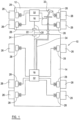
- the CAN hub 44 includes 4 connectors, 60, 62, 64, 66.
- the functions of the connectors 60, 62, 64, 66 may be as follows.
- the connector 60 is an auxiliary connection, for example a connector for a pressure transducer
- a connector 62 is a front 'predecessor' or 'towed' connector, to connect to a predecessor, which may be the tractor 12, or the trailer ahead of the trailer bearing the CAN hub 44 in question
- the connector 64 is a rear, 'successor' or 'towing' connector, for connecting to a rearward 'successor' trailer
- the connector 66 is a local connector, which connects to the ECU 18 on the same trailer as that associated with the CAN hub 44 in question.
- the functions of the connectors 60-66 are permanently configured and arranged.
- the pinouts and keying of the connector ports may be identical for each port.
- the present invention enables the configuration and/or reconfiguration of at least one of the functions of the hub, i.e. as a repeater, a router for towing trailer or a router for a multiple EBS system, via an automatic or semiautomatic procedure.
- the CAN hub 25 and the CAN hub 44 can be physically identical to one another, and may be configured and/or reconfigured to adopt its required function, or even to change its function depending upon the configuration of the vehicle. Additionally or alternatively, the allocation of each connector port may also be configured and/or reconfigured automatically or semi-automatically.
- An EBS for a trailer is typically connected to a workshop computer (tester) in order to program parameters within the EBS and carry out a functional test.
- This connection may be made to a dedicated diagnostics port on the EBS.
- the connection is made via the ISO7638 connector at the front of the trailer, i.e. the headboard connector 24.
- the communication is made via the CAN bus 20.
- the trailer is fitted with a CAN hub 25, 44, irrespective of the function of the CAN hub 25, 44, it is still possible to perform this 'end-of-line' procedure via the connector 24, where provided.
- the CAN hub 25, 44 facilitates this by passing on messages intended for the trailer EBS (rearwards) or for the tester (forwards).
- the tester is able to communicate with the CAN hub 25, 44 directly.
- the CAN hub 25, 44 may make inferences about the desired/required function of each of the connector ports. Such inferences may be made automatically. It is also possible to use any of the connectors for any function.
- the tester initiates an 'end-of-line' mode, in other words a 'configuration mode'.
- the CAN hub 25, 44 recognises the tester port as the 'towed node' and saves this information in memory.
- the CAN hub 25, 44 may then automatically recognise the connection of one or two electronic braking systems on the other nodes.
- the CAN hub configuration is a 'two EBS router'.
- the CAN hub 44 saves this information in memory.
- the vehicle identification number (VIN) which is broadcast on each CAN node by the two EBS is also saved in memory.
- the VIN is programmed by the tester as part of the end-of-line procedure and subsequently continuously broadcast by the EBS in a running gear equipment (RGE) message, e.g. RGE23, which is a message sent forward in the train by trailer nodes. Local nodes may be identified by the trailer VIN which is broadcast in the RGE message.
- RGE running gear equipment
- the configuration of the CAN hub 25, 44 is either a 'repeater' or a ⁇ towing trailer router'.
- the node without an EBS connected to it is, by default, a towing node, irrespective of whether or not it is connected to a towing ISO7638 connector.
- the CAN hub 25, 44 saves this information to memory.
- the local VIN is also stored in memory.
- a brake demand message for example an EBS11 message, is broadcast rearwards to each trailer in the train, every 10 milliseconds.
- the brake demand message can be used to identify ⁇ predecessor nodes', i.e. the tractor/trailer ahead of the trailer receiving the brake demand message.
- Local nodes are identified by a recognised trailer VIN broadcast in an RGE message, e.g. RGE 23.
- 'Successor nodes' may be identified either by a 'no reception' message, i.e. nothing is identified as being connected to the connector, or an unknown trailer VIN being broadcast in the RGE23 message.
- CAN bus 20 It is possible for the CAN bus 20 to be used to reconfigure the system, in service, for example following maintenance. As mentioned above, there is a risk that even in systems where permanent labels are provided adjacent connectors, that cables may be connected to the wrong connector after disconnection.
- the present invention makes it possible to detect such errors and to correctly re-configure any wrongly connected connectors.
- a signal may be provided to a driver that there are wrongly connected connectors.
- a signal may be provided by lighting a warning lamp in the driver's cab, which may be performed by the hub 25, 44, for example by connecting pin 5 of the ISO7638 to ground. It is also possible for the hub to light a warning lamp via the ISO11992 CAN bus.
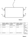
- a table of possible errors and error actions (to reconfigure the CAN hub 25, 44) is provided in Figure 5 . In the event that all the connections are as expected (line 1 of the table), then no reconfiguration is required.
- the CAN hub 25, 44 is able to configure itself as either a repeater or a router, dependent upon the configuration of the vehicle, it is possible for each trailer to be provided with a CAN hub 25, 44, and it is not necessary to replace the device if the vehicle configuration is changed.
- the CAN hub 25, 44 may automatically configure itself to perform the function that is required of it, dependent upon the signals it receives from its local ECU 18 (i.e. the ECU associated with the trailer 14 with which the CAN hub 25, 44 is associated) and the ECU 16, 18 of the predecessor (i.e. the tractor ECU or the ECU of the trailer 14 ahead of the associated trailer) and/or the ECU of a successor 14, 15 (where present).
Landscapes
- Engineering & Computer Science (AREA)
- Transportation (AREA)
- Mechanical Engineering (AREA)
- Regulating Braking Force (AREA)
Description
- This invention relates to a vehicle braking system, in particular, a vehicle braking system for a vehicle including a tractor and one or more trailers.
- In vehicles including a tractor (i.e. a towing vehicle) and a trailer and/or semi-trailer, where braking is controlled by an electronic braking system (EBS), it is known to provide the tractor with an electronic control unit (ECU) to control braking of the tractor and the trailer with a separate ECU to control braking of the trailer. An electronic braking demand signal generated by a driver of the vehicle, for example by actuating a foot brake pedal, is transmitted to the tractor ECU, which determines the required braking force, and transmits the appropriate braking signals to brake actuators provided for the wheels of the tractor. The tractor ECU also transmits the braking demand signal to the trailer ECU to enable the trailer ECU to transmit appropriate braking signals to the brake actuators provided for the wheels of the trailer.
- An EBS of known type may be used in conjunction with tractors having interfaces conforming to ECE Regulation 13, e.g. having one pneumatic supply line and one pneumatic control line; one pneumatic supply line, one pneumatic control line and one electric control line; or one pneumatic supply line and one electric control line. The latter configuration is not currently permitted, but EBS systems which support this configuration are known (for example the Haldex Brake Products EB+ system). The electric control line is both the electrical power and data communication connection between the tractor and the trailer(s).
-
EP2658181 discloses a connection device for communication between two vehicles, the connection device comprising a data line and two plug connections. A data splitter is provided between the data line and the plug connections. The two plug connections are assigned different conduction paths. The data splitter checks the plugged in plug connection and activates the assigned conduction path. One of the conduction paths is activated when both plug connections are used. - A typical electronic braking system is illustrated in
Figure 1 . An articulatedvehicle 10 is fitted with an electronic braking system (EBS). Thevehicle 10 includes atractor 12 and atrailer 14, thetractor 12 having a main braking electronic control unit (ECU) 16 and thetrailer 14 having a main braking electronic control unit (ECU) 18, the two ECUs being connected together by means of aCAN bus 20 and atractor connector 22 mounted on the rear of thetractor 12 and atrailer connector 24 mounted on the front of thetrailer 14. Thetractor 12 andtrailer 14 are each provided with a plurality ofwheels 26 each of which is provided with abrake 28 which is operated by anactuator 30. In this example, theactuators 30 are pneumatically operable, and are therefore connected to a source of pressurised fluid (in this example compressed air) via amodulator 32. Eachmodulator 32 is electrically operable and receives an electrical signal input from one of theECUs wheels 26 at of thetractor 12 ortrailer 14, respectively, in response to an electrical braking signal from therespective ECU - The
CAN bus 20 is ISO11992 compliant and the twoconnectors CAN bus 20 which extends between thetractor ECU 16 and the tractor-mountedconnector 22 is no more than 15m long, the portion of theCAN bus 20 which extends between the tractor-mountedconnector 22 and the trailer-mountedconnector 24 is no more than 7m long, whilst the portion of theCAN bus 20 which extends between thetrailer connector 24 and the trailer ECU 18 is no more than 18m long. - The system is also provided with a pneumatic back-up to enable braking of the
trailer 14 in the absence of an electrical braking demand signal from thetractor 12, for example because of an electrical power failure in thetractor 12, because there is a fault in theCAN bus 20 or theconnectors pneumatic line 34 from the tractor to a pressure input in the trailer ECU 18. The trailer ECU 18 is provided with a pressure transducer which measures the pressure of the pneumatic braking demand signal, and converts it to an electrical braking demand signal, which it then uses to generate appropriate braking signals for transmission to themodulator 32 of thetrailer 14. - It is known to provide repeaters and routers (described in more detail below) to enable longer distances to be covered by the CAN bus. Such repeaters and routers provide for different situations, and have different functions. Each repeater or router has a number of connectors for connecting the device to the other components of the EBS. The properties and functions of each repeater or router device and its respective connectors are permanently configured and arranged prior to installation of the device in the vehicle EBS. Furthermore, the pinouts and keying of the connectors may be identical for each port. This presents a problem that during installation and/or servicing, some or all of the cables could be connected or reconnected to an incorrect port. The ports may be labelled, either permanently on the exterior of the device, or by means of labels attached to the device. However, this does not prevent labels being damaged/erased or the possibility of a label being misread or disregarded.
- The present invention is defined in
independent claim 1 and relates to a hub device for use in a vehicle braking system which includes an electronic braking system and a CAN bus. - Preferred embodiments of the invention are defined in the dependent claims.
- In accordance with embodiments of the present invention, there is provided a vehicle braking system for a vehicle including a tractor and at least one trailer, the vehicle braking system including an electronic braking system including a respective electronic control unit for the tractor and the or each trailer, a CAN bus to enable communication between the electronic control units of the tractor and the or each trailer, and a hub device which is able to communicate electrical signals, including a braking demand signal, to components of the electronic braking system, and to function as at least one of a CAN bus repeater and a CAN bus router, wherein the hub device is operable to determine its required function based upon signals received by the hub device from the electronic control unit of the trailer with which the hub device is associated, and one or more of the electronic control units of the tractor and the or each other trailer, where one or more additional trailers is provided.
- The hub device may include a plurality of connectors, and the hub device may be operable to configure each of its connectors dependent upon one or more signals received by each connector, and/or a lack of a signal received by one or more of the connectors.
- The hub device may be operable to configure its connectors during an end-of-line procedure.
- The hub device may be operable to configure its connectors during operation of the braking system, and/or during or after maintenance of the braking system.
- Where there are multiple trailers, each trailer of the vehicle may include an associated hub device.
- Each trailer except the final trailer in a train may include a hub device.
- The vehicle braking system may include a plurality of hub devices, wherein communication between the electronic control units of the tractor and/or the or each trailer, is carried out via one or more of the hub devices.
- There is also provided a hub device for use in a vehicle braking system which includes an electronic braking system and a CAN bus, the hub device including a plurality of connectors, wherein the hub device is operable to configure a function of one or more of the connectors based upon a signal received by or the lack of a signal received by one or more of the connectors.
- The hub device may be operable to determine its required function as either a CAN bus repeater or a CAN bus router based upon based upon signals received by the hub device from the electronic control unit of a trailer with which the hub device is associated, and one or more electronic control units associated with a tractor of the vehicle and/or one or more other trailers, where one or more additional trailers is provided.
- There is also provided a vehicle including a braking system as described herein.
- There is also provided a vehicle including a hub device as described herein.
- Embodiments of the invention will now be described, by way of example only, with reference to the accompanying drawings, of which
-
FIGURE 1 is a schematic illustration of a prior art vehicle braking system; -
FIGURE 2 is a schematic illustration of a vehicle braking system including a repeater device; -
Figure 3 is a schematic illustration of a vehicle braking system including a router device; -
FIGURE 4 is a schematic illustration of a hub device in accordance with the present invention; and -
FIGURE 5 is a table showing possible connections made to a hub device and outcomes of such connections. - Referring to
Figure 2 , there is shown a schematic illustration of avehicle 10 having a braking system similar to that shown inFigure 1 . Identical parts have identical reference numerals. InFigure 2 , the trailer-mountedconnector 24 has been replaced by aCAN hub 25 rather than a conventional ISO7638 connector (which acts as a straightforward junction box). - In an embodiment, the CAN
hub 25 acts as a repeater and retransmits any signals it receives. Since theCAN hub repeater 25 is therefore the originator of any signal that it transmits, the system is now considered to be provided with two CAN buses - the first 20a extending between thetractor ECU 16 and theCAN hub 25 and the second 20b extending between theCAN hub 25 and the trailer ECU - both of which can be up to 40 metres long. By virtue of the replacement of thetrailer connector 24 with theCAN hub 25, electrical control of braking can be maintained even if the system is used on a trailer where long control lines are required, for example an extendable trailer which is fully extended. TheCAN hub repeater 25 receives all seven cores from thetractor connector 22, including the ISO11992 data communication part of the electrical control line, acts as an intermediate CAN node and then connects to the trailer ECU 18 via a seven-core cable of up to 40 metres. - Whilst the
connector 24 is described above as being replaced by theCAN hub repeater 25, theCAN hub repeater 25 may be provided in addition to theconnector 24. - The
trailer 14 is also provided with aheadboard pressure sensor 36 which measures the pressure in thepneumatic line 34 as close to the front of the trailer (the trailer headboard) as possible. In this example, theheadboard pressure sensor 36 is mounted in thepneumatic line 34 between a trailer coupling 38, by means of which the pneumatic line from thetractor 12 is coupled to thetrailer 14, and a relay valve 40 which acts to boost the braking demand signal transmitted to the trailer ECU 18. Theheadboard pressure sensor 36 generates an electrical signal which is indicative of the pressure in thepneumatic line 34, and which therefore constitutes a replacement electrical braking demand signal. Theheadboard pressure sensor 36 is connected to an electrical input of theCAN hub 25 and theCAN hub 25 is configured such that the replacement electrical braking demand signal from thepressure sensor 36 can be transmitted to the trailer ECU 18 via thesecond CAN bus 20b. - The trailer ECU 18 can then treat the electrical braking demand signal generated by the
headboard pressure sensor 36 as if it were an electrical braking demand signal transmitted from thetractor 12, and generate the braking signals for transmission to themodulators 32 on the basis of this electrical braking demand signal rather than on the basis of the electrical signal derived from the pneumatic braking demand signal received by the trailer ECU 18 via thepneumatic line 34. - The provision of such a
headboard pressure sensor 36 is particularly advantageous because the braking demand signal can be transmitted very quickly to the trailer ECU 18 via thesecond CAN bus 20b, and without the need to provide any additional wiring. This overcomes the problem of delay in operation of the trailer brakes caused by the length of time the pneumatic braking demand signal takes to travel along thepneumatic line 34 to the trailer ECU 18, particular if thetrailer 14 is extended by any significant degree. - It will be appreciated that the invention may equally be applied to other configurations of electrical braking system. For example, each modulator 32 may be connected to a
single brake actuator 30, or to all thebrake actuators 30 acting on the wheels on one axle of thetractor 12 ortrailer 14. Advantageously, as is conventional in most, if not all, vehicles fitted with EBS, theECUs - Embodiments of the invention may be used for tractor and full trailer or tractor and semi-trailer combinations. ISO11992 allows for a tractor and up to five trailers to be connected together.
Figure 3 shows a tractor and two trailers connected together. - Referring to
Figure 3 , there is shown atractor 12, a first 'predecessor'trailer 14 and a second 'successor'trailer 15. It will be understood that since up to five trailers may be provided, in accordance with ISO11992, the or each trailer is the successor to the trailer (or tractor in the case of a single trailer) ahead of it, and each trailer having a trailer behind it is the predecessor to the trailer behind it. The predecessor to thefirst trailer 14 is the tractor 12 (thetractor 12 cannot be a successor because it is always the first unit in a train). In a tractor and semi-trailer combination, if the tractor is not configured correctly to support a semi-trailer, a dolly may be provided between the tractor and the semi-trailer - the dolly supporting the semi-trailer and being towed by the tractor. In this case, the system may be configured as shown inFigure 3 , with the dolly corresponding to thefirst trailer 14. - The
tractor 12 and eachtrailer braking control unit modulator 32 and abrake 28, and abrake actuator 30 associated with eachwheel 26. Abrake pedal 33, positioned in a driver's cab of thetractor 12, is connected to thetractor ECU 16 and is operable to transmit to thetractor ECU 16 an electrical braking demand signal which is used to generate a braking signal which is transmitted to themodulators 32. - The
tractor ECU 16 is connected to each of thetrailer ECUs 18 using aCAN bus 20, so that the electrical braking demand signal can be transmitted to thetrailer ECUs 18. In order to facilitate this connection there is an ISO 7638compliant connector 22 provided at the rear of thetractor 12, aCAN hub 44 at the front of thefirst trailer 14, a further ISO 7638compliant connector 46 at the rear of thefirst trailer 14 and a further ISO 7638compliant connector 24 provided at the front of thesecond trailer 15. TheCAN bus 20 extends from the tractor mountedconnector 22 to theCAN hub 44, on to therear connector 46 of thefirst trailer 14, the front (headboard)connector 24 of the second trailer, and finally the second trailerelectrical control unit 18. In such an embodiment, or where further trailers are provided, theCAN hub 44 acts as a router. - In embodiments, a
pneumatic line 34 extends from thebrake pedal 33 to each of thetrailer ECUs 18, and provides means of communicating a pneumatic braking demand signal to thetrailer ECUs 18 as a back-up to the electrical braking demand signal as discussed above. - The
CAN bus 20 connecting theCAN hub 44 to theconnector 46 at the rear of thefirst trailer 14 is connected to a first port of theCAN hub 44, and theCAN bus 50 connecting theCAN hub 44 to thefirst trailer ECU 18 is connected to a second port of theCAN hub 44. By virtue of this arrangement, only a single electrical connection between thetractor 12 and thetrailer 14 is required in order to supply electrical power, and perhaps also an electrical braking demand signal to thetrailer ECU 18. - The second port of the
CAN hub 44 may provide a five pin connection to thefirst trailer ECU 18, the five pin connection being used to provide electrical power to thetrailer ECU 18, and, if desired, ignition on/off and cab-mounted warning lamp signals. In this case, thetrailer ECU 18 may be able to provide ABS functionality only and not a full EBS. The second port of theCAN hub 44 may, alternatively provide an ISO7638 standard seven pin connection, in which case, the dolly electricalbraking control unit 18 may also be supplied with the electrical braking demand signal via this connection, and can function as an EBS unit. In such an embodiment, CANhub 44 acts as a router. Thefirst trailer ECU 18 receives all seven cores from thesecond trailer connector 24, including the ISO 11992 communication part of the electrical control line, provides two intermediate ISO 11992 CAN nodes, connecting the first to thefirst trailer ECU 18 via a seven-core cable of up to 40 metres in length and the second to thetractor connector 22. - Where the five-pin port of the
CAN hub 44 is used, if thedolly 14 is to be provided with EBS, it is necessary for thedolly 14 to receive the pneumatic braking demand signal from thepneumatic line 34, and thetrailer ECU 18 to be provided with a pressure transducer to convert the pneumatic signal to an electrical braking demand signal for processing by thetrailer ECU 18. - In the
Figure 3 arrangement, thesecond trailer 15 could also be provided with a CAN hub to enable the connection of an additional trailer, i.e. a successor to thesecond trailer 15. The second trailer 15 (and additional trailers) can also be provided with a headboard pressure sensor as described in relation toFigure 2 above. The pressure sensor may be connected to an auxiliary port on the associatedCAN hub 44 instead of the associatedECU 18. This limits the number of long cable runs. TheCAN hub 44 uses the intermediate CAN node to send a signal from the pressure sensor when there is no electric control line available on thetractor 12. - Where additional trailers are provided, it will be appreciated that the final trailer in the series will be configured substantially as the
second trailer 15 as shown inFigure 3 , and each of the other trailers (each being both a predecessor and a successor) will be configured substantially as thefirst trailer 14 ofFigure 3 . - The
CAN hub 44 may be provided for different situations, for example the configuration of aCAN hub 44 when it is to be used as a repeater may be different from the configuration of aCAN hub 44 when it is used as a router. It is known to use different connector ports for different functions, for example, the CAN hub may have a dedicated connector port for each of a towed/front/predecessor node, local node, towing/rear/successor node and auxiliary node. - An embodiment of a
CAN hub 44 is shown inFigure 4 . TheCAN hub 44 includes 4 connectors, 60, 62, 64, 66. The functions of theconnectors connector 60 is an auxiliary connection, for example a connector for a pressure transducer, aconnector 62 is a front 'predecessor' or 'towed' connector, to connect to a predecessor, which may be thetractor 12, or the trailer ahead of the trailer bearing theCAN hub 44 in question, theconnector 64 is a rear, 'successor' or 'towing' connector, for connecting to a rearward 'successor' trailer, and theconnector 66 is a local connector, which connects to theECU 18 on the same trailer as that associated with theCAN hub 44 in question. As mentioned above, in known devices, the functions of the connectors 60-66 are permanently configured and arranged. Furthermore, the pinouts and keying of the connector ports may be identical for each port. - The present invention enables the configuration and/or reconfiguration of at least one of the functions of the hub, i.e. as a repeater, a router for towing trailer or a router for a multiple EBS system, via an automatic or semiautomatic procedure. This means that the
CAN hub 25 and theCAN hub 44 can be physically identical to one another, and may be configured and/or reconfigured to adopt its required function, or even to change its function depending upon the configuration of the vehicle. Additionally or alternatively, the allocation of each connector port may also be configured and/or reconfigured automatically or semi-automatically. - An EBS for a trailer is typically connected to a workshop computer (tester) in order to program parameters within the EBS and carry out a functional test. This connection may be made to a dedicated diagnostics port on the EBS. Typically, the connection is made via the ISO7638 connector at the front of the trailer, i.e. the
headboard connector 24. The communication is made via theCAN bus 20. Where the trailer is fitted with aCAN hub CAN hub connector 24, where provided. TheCAN hub CAN hub - It is also possible for the
CAN hub - In an embodiment, the tester initiates an 'end-of-line' mode, in other words a 'configuration mode'. The
CAN hub CAN hub - Where there are two EBS, then the CAN hub configuration is a 'two EBS router'. The
CAN hub 44 saves this information in memory. The vehicle identification number (VIN), which is broadcast on each CAN node by the two EBS is also saved in memory. The VIN is programmed by the tester as part of the end-of-line procedure and subsequently continuously broadcast by the EBS in a running gear equipment (RGE) message, e.g. RGE23, which is a message sent forward in the train by trailer nodes. Local nodes may be identified by the trailer VIN which is broadcast in the RGE message. - Where there is only one EBS then the configuration of the
CAN hub CAN hub - A brake demand message, for example an EBS11 message, is broadcast rearwards to each trailer in the train, every 10 milliseconds. The brake demand message can be used to identify `predecessor nodes', i.e. the tractor/trailer ahead of the trailer receiving the brake demand message. Local nodes are identified by a recognised trailer VIN broadcast in an RGE message, e.g. RGE 23.
- 'Successor nodes' may be identified either by a 'no reception' message, i.e. nothing is identified as being connected to the connector, or an unknown trailer VIN being broadcast in the RGE23 message.
- It is possible for the
CAN bus 20 to be used to reconfigure the system, in service, for example following maintenance. As mentioned above, there is a risk that even in systems where permanent labels are provided adjacent connectors, that cables may be connected to the wrong connector after disconnection. The present invention makes it possible to detect such errors and to correctly re-configure any wrongly connected connectors. Additionally or alternatively, a signal may be provided to a driver that there are wrongly connected connectors. Such a signal may be provided by lighting a warning lamp in the driver's cab, which may be performed by thehub - A table of possible errors and error actions (to reconfigure the
CAN hub 25, 44) is provided inFigure 5 . In the event that all the connections are as expected (line 1 of the table), then no reconfiguration is required. - In the event that the
local connection 66 and the towing/successor/rear connection 64 have been switched (line 2), then theCAN hub connectors - In the event that an unrecognised/unexpected VIN is received at the
local connection 66, and the local VIN is received at the towing/successor/rear connection 66 (line 3), this indicates that an incorrect trailer has been connected as the successor. In this event, a warning signal is sent to the driver's cab. The next time that the system is powered on, an automatic reconfiguration is carried out, so that the new VIN is recognised and accepted. - In the event that the local connection receives an unrecognised VIN and the towing/successor/rear connection receives either no VIN or an unrecognised/unexpected VIN (line 4), then a warning signal is sent to the driver's cab, and manual intervention is required. This indicates that an unexpected or unrecognised trailer has been connected to the local connector, and the local connection which was expected is missing.
- In the event that the
local connection 66 and the front/towed/predecessor connection 62 are switched (line 5), then an automatic reconfiguration of thoseconnectors CAN hub 44 is reconfigured for use in its present arrangement and no manual replacement of the cables is required for the EBS to function correctly. - Since the
CAN hub CAN hub CAN hub trailer 14 with which theCAN hub ECU trailer 14 ahead of the associated trailer) and/or the ECU of asuccessor 14, 15 (where present). - It is also possible to completely reconfigure the
hub - By continually (i.e. frequently, not necessarily continuously) assessing the signals received by each node of the or each CAN
hub - Whilst the connectors described above are ISO7638 compliant, it should be appreciated that this is not essential to the invention, and any other type of connector capable of relaying the required signals may be used.
- It will be appreciated that whilst each CAN
hub trailer 14 with which it is associated, this is not necessary for the invention. - When used in this specification and claims, the terms "comprises" and "comprising" and variations thereof mean that the specified features, steps or integers are included. The terms are not to be interpreted to exclude the presence of other features, steps or components.
Claims (10)
- A hub device (25, 44) for use in a vehicle braking system which includes an electronic braking system and a CAN bus (20, 20a, 20b), characterised in that the hub device (25, 44) is operable to communicate electrical signals, including a braking demand signal, to components of the electronic braking system, and to function as either a CAN bus repeater or a CAN bus router, and is operable to determine its required function as either a CAN bus repeater or a CAN bus router based upon signals received by the hub device (25, 44) from the electronic control unit (18) of a trailer (14, 15) with which the hub device (25, 44) is associated, and one or more electronic control units (16, 18) associated with a tractor (12) of the vehicle (10) and/or one or more other trailers (14, 15), where one or more additional trailers (15) is provided.
- A hub device (25, 44) according to claim 1 including a plurality of connectors (60, 62, 64, 66), the hub device (25, 44) being operable to configure a function of one or more of the connectors (60, 62, 64, 66) based upon a signal received by or the lack of a signal received by one or more of the connectors (60, 62, 64, 66).
- A vehicle braking system for a vehicle (10) including a tractor (12) and at least one trailer (14, 15), the vehicle braking system including an electronic braking system including a respective electronic control unit (16, 18) for the tractor (12) and the or each trailer (14, 15), a CAN bus (20, 20a, 20b) to enable communication between the electronic control units (16, 18) of the tractor (12) and the or each trailer (14, 15), and a hub device (25, 44) according to claim 1 or claim 2.
- A vehicle braking system according to claim 3, as dependent on claim 2 wherein the hub device (25, 44) is operable to configure its connectors (60, 62, 64, 66) during an end-of-line procedure.
- A vehicle braking system according to claim 3 as dependent on claim 2 wherein the hub device (25, 44) is operable to configure its connectors (60, 62, 64, 66) during operation of the braking system, and/or during or after maintenance of the braking system.
- A vehicle braking system according to any of claims 3 to 5, wherein each trailer (14) of the vehicle (10) includes an associated hub device (25, 44).
- A vehicle braking system according to any of claims 3 to 5 wherein each trailer (14) except the final trailer (15) in a train includes a hub device (25, 44).
- A vehicle braking system according to any of claims 3 to 7, including a plurality of hub devices (25, 44), wherein communication between the electronic control units (16, 18) of the tractor (12) and/or the or each trailer (14, 15), is carried out via one or more of the hub devices (25, 44).
- A vehicle (10) including a braking system according to any of claims 3 to 8.
- A vehicle (10) including a hub device (25, 44) according to claim 1 or claim 2.
Applications Claiming Priority (2)
| Application Number | Priority Date | Filing Date | Title |
|---|---|---|---|
| GB1721492.5A GB2569592B (en) | 2017-12-20 | 2017-12-20 | Braking system |
| PCT/EP2018/077036 WO2019120660A1 (en) | 2017-12-20 | 2018-10-04 | Braking system |
Publications (2)
| Publication Number | Publication Date |
|---|---|
| EP3727963A1 EP3727963A1 (en) | 2020-10-28 |
| EP3727963B1 true EP3727963B1 (en) | 2024-02-14 |
Family
ID=61009154
Family Applications (1)
| Application Number | Title | Priority Date | Filing Date |
|---|---|---|---|
| EP18785896.4A Active EP3727963B1 (en) | 2017-12-20 | 2018-10-04 | Hub device for use in a vehicle braking system |
Country Status (4)
| Country | Link |
|---|---|
| EP (1) | EP3727963B1 (en) |
| AU (1) | AU2018390760B2 (en) |
| GB (1) | GB2569592B (en) |
| WO (1) | WO2019120660A1 (en) |
Family Cites Families (11)
| Publication number | Priority date | Publication date | Assignee | Title |
|---|---|---|---|---|
| DE19944132A1 (en) * | 1999-09-15 | 2001-08-09 | Krauss Maffei Wegmann Gmbh & C | System for the process-controlled transmission of electrical signals and electrical energy within a military vehicle |
| DE10216564B4 (en) * | 2002-04-15 | 2015-12-17 | Wabco Gmbh | Method for data exchange in a vehicle, in which the individual vehicle parts are interconnected via a PLC data bus |
| US8532850B2 (en) * | 2009-03-17 | 2013-09-10 | General Electric Company | System and method for communicating data in locomotive consist or other vehicle consist |
| AU2013219219B2 (en) * | 2008-07-19 | 2015-11-26 | Haldex Aktiebolag | Vehicle Braking System |
| GB2462072B (en) * | 2008-07-19 | 2013-02-13 | Haldex Brake Products Ltd | Vehicle braking system |
| GB2493478B (en) * | 2008-07-19 | 2013-05-22 | Haldex Brake Products Ltd | Vehicle braking system |
| GB0813822D0 (en) * | 2008-07-29 | 2008-09-03 | Knorr Bremse Systeme | Trailer electronic breaking system |
| DE102009008342B4 (en) * | 2009-02-11 | 2015-09-10 | Knorr-Bremse Systeme für Nutzfahrzeuge GmbH | Control and monitoring device of a vehicle with integrated in a unit tire monitoring control unit and brake control unit |
| DE102012008408A1 (en) * | 2012-04-27 | 2013-10-31 | Wabco Gmbh | Connection device for data communication between two vehicles |
| DE102012014408A1 (en) * | 2012-07-19 | 2014-01-23 | Wabco Gmbh | A method of braking a combination of a plurality of coupled vehicles |
| US10814844B2 (en) * | 2017-09-15 | 2020-10-27 | Bendix Commercial Vehicle Systems Llc | Braking controller and method using verification of reported trailer capabilities |
-
2017
- 2017-12-20 GB GB1721492.5A patent/GB2569592B/en not_active Withdrawn - After Issue
-
2018
- 2018-10-04 AU AU2018390760A patent/AU2018390760B2/en active Active
- 2018-10-04 WO PCT/EP2018/077036 patent/WO2019120660A1/en not_active Ceased
- 2018-10-04 EP EP18785896.4A patent/EP3727963B1/en active Active
Also Published As
| Publication number | Publication date |
|---|---|
| WO2019120660A1 (en) | 2019-06-27 |
| AU2018390760B2 (en) | 2023-08-03 |
| GB201721492D0 (en) | 2018-01-31 |
| GB2569592A (en) | 2019-06-26 |
| AU2018390760A1 (en) | 2020-05-07 |
| GB2569592B (en) | 2022-08-17 |
| EP3727963A1 (en) | 2020-10-28 |
Similar Documents
| Publication | Publication Date | Title |
|---|---|---|
| US5397924A (en) | Truck tractor and trailer electrical communication system | |
| EP2450248B1 (en) | Vehicle Braking System | |
| EP0546370B1 (en) | Truck tractor and trailer electrical communication system | |
| EP3962790B1 (en) | Trailer braking system | |
| US12049205B2 (en) | Trailer braking system | |
| CN102712229B (en) | Connecting device and the trailer with connecting device of trailer | |
| CN102202946A (en) | Control arrangement for a trailer vehicle | |
| CN112203877A (en) | Truck trailer interface | |
| EP3727963B1 (en) | Hub device for use in a vehicle braking system | |
| US9725078B2 (en) | Cabling device and electronic brake system for a modular heavy goods vehicle and for a heavy goods vehicle | |
| GB2493478A (en) | Vehicle braking system, for an articulated vehicle having a tractor, a first trailer and a second trailer | |
| CN110758285B (en) | Vehicle electrical and CAN communication connection establishing device and method | |
| AU2013219219B2 (en) | Vehicle Braking System | |
| EP4587305B1 (en) | Truck trailer interface | |
| CN120187607A (en) | Switching device for a trailer comprising a lighting device for a multi-section vehicle, in particular a commercial vehicle, and trailer | |
| CN211166744U (en) | Electrical CAN communication connecting device between tractor and trailer and between trailer | |
| WO2024042144A1 (en) | Trailer brake system |
Legal Events
| Date | Code | Title | Description |
|---|---|---|---|
| STAA | Information on the status of an ep patent application or granted ep patent |
Free format text: STATUS: UNKNOWN |
|
| STAA | Information on the status of an ep patent application or granted ep patent |
Free format text: STATUS: THE INTERNATIONAL PUBLICATION HAS BEEN MADE |
|
| PUAI | Public reference made under article 153(3) epc to a published international application that has entered the european phase |
Free format text: ORIGINAL CODE: 0009012 |
|
| STAA | Information on the status of an ep patent application or granted ep patent |
Free format text: STATUS: REQUEST FOR EXAMINATION WAS MADE |
|
| 17P | Request for examination filed |
Effective date: 20200424 |
|
| AK | Designated contracting states |
Kind code of ref document: A1 Designated state(s): AL AT BE BG CH CY CZ DE DK EE ES FI FR GB GR HR HU IE IS IT LI LT LU LV MC MK MT NL NO PL PT RO RS SE SI SK SM TR |
|
| AX | Request for extension of the european patent |
Extension state: BA ME |
|
| DAV | Request for validation of the european patent (deleted) | ||
| DAX | Request for extension of the european patent (deleted) | ||
| STAA | Information on the status of an ep patent application or granted ep patent |
Free format text: STATUS: EXAMINATION IS IN PROGRESS |
|
| 17Q | First examination report despatched |
Effective date: 20220811 |
|
| GRAP | Despatch of communication of intention to grant a patent |
Free format text: ORIGINAL CODE: EPIDOSNIGR1 |
|
| STAA | Information on the status of an ep patent application or granted ep patent |
Free format text: STATUS: GRANT OF PATENT IS INTENDED |
|
| INTG | Intention to grant announced |
Effective date: 20230619 |
|
| P01 | Opt-out of the competence of the unified patent court (upc) registered |
Effective date: 20230710 |
|
| GRAJ | Information related to disapproval of communication of intention to grant by the applicant or resumption of examination proceedings by the epo deleted |
Free format text: ORIGINAL CODE: EPIDOSDIGR1 |
|
| STAA | Information on the status of an ep patent application or granted ep patent |
Free format text: STATUS: EXAMINATION IS IN PROGRESS |
|
| INTC | Intention to grant announced (deleted) | ||
| GRAP | Despatch of communication of intention to grant a patent |
Free format text: ORIGINAL CODE: EPIDOSNIGR1 |
|
| STAA | Information on the status of an ep patent application or granted ep patent |
Free format text: STATUS: GRANT OF PATENT IS INTENDED |
|
| INTG | Intention to grant announced |
Effective date: 20231113 |
|
| GRAS | Grant fee paid |
Free format text: ORIGINAL CODE: EPIDOSNIGR3 |
|
| GRAA | (expected) grant |
Free format text: ORIGINAL CODE: 0009210 |
|
| STAA | Information on the status of an ep patent application or granted ep patent |
Free format text: STATUS: THE PATENT HAS BEEN GRANTED |
|
| AK | Designated contracting states |
Kind code of ref document: B1 Designated state(s): AL AT BE BG CH CY CZ DE DK EE ES FI FR GB GR HR HU IE IS IT LI LT LU LV MC MK MT NL NO PL PT RO RS SE SI SK SM TR |
|
| REG | Reference to a national code |
Ref country code: GB Ref legal event code: FG4D |
|
| REG | Reference to a national code |
Ref country code: CH Ref legal event code: EP |
|
| REG | Reference to a national code |
Ref country code: DE Ref legal event code: R096 Ref document number: 602018065235 Country of ref document: DE |
|
| REG | Reference to a national code |
Ref country code: IE Ref legal event code: FG4D |
|
| REG | Reference to a national code |
Ref country code: SE Ref legal event code: TRGR |
|
| REG | Reference to a national code |
Ref country code: GB Ref legal event code: 732E Free format text: REGISTERED BETWEEN 20240425 AND 20240501 |
|
| REG | Reference to a national code |
Ref country code: LT Ref legal event code: MG9D |
|
| REG | Reference to a national code |
Ref country code: NL Ref legal event code: MP Effective date: 20240214 |
|
| REG | Reference to a national code |
Ref country code: DE Ref legal event code: R081 Ref document number: 602018065235 Country of ref document: DE Owner name: HALDEX AB, SE Free format text: FORMER OWNER: HALDEX BRAKE PRODUCTS AB, LANDSKRONA, SE |
|
| PG25 | Lapsed in a contracting state [announced via postgrant information from national office to epo] |
Ref country code: IS Free format text: LAPSE BECAUSE OF FAILURE TO SUBMIT A TRANSLATION OF THE DESCRIPTION OR TO PAY THE FEE WITHIN THE PRESCRIBED TIME-LIMIT Effective date: 20240614 |
|
| PG25 | Lapsed in a contracting state [announced via postgrant information from national office to epo] |
Ref country code: LT Free format text: LAPSE BECAUSE OF FAILURE TO SUBMIT A TRANSLATION OF THE DESCRIPTION OR TO PAY THE FEE WITHIN THE PRESCRIBED TIME-LIMIT Effective date: 20240214 |
|
| PG25 | Lapsed in a contracting state [announced via postgrant information from national office to epo] |
Ref country code: GR Free format text: LAPSE BECAUSE OF FAILURE TO SUBMIT A TRANSLATION OF THE DESCRIPTION OR TO PAY THE FEE WITHIN THE PRESCRIBED TIME-LIMIT Effective date: 20240515 |
|
| REG | Reference to a national code |
Ref country code: AT Ref legal event code: MK05 Ref document number: 1656801 Country of ref document: AT Kind code of ref document: T Effective date: 20240214 |
|
| RAP2 | Party data changed (patent owner data changed or rights of a patent transferred) |
Owner name: HALDEX AKTIEBOLAG |
|
| PG25 | Lapsed in a contracting state [announced via postgrant information from national office to epo] |
Ref country code: HR Free format text: LAPSE BECAUSE OF FAILURE TO SUBMIT A TRANSLATION OF THE DESCRIPTION OR TO PAY THE FEE WITHIN THE PRESCRIBED TIME-LIMIT Effective date: 20240214 Ref country code: RS Free format text: LAPSE BECAUSE OF FAILURE TO SUBMIT A TRANSLATION OF THE DESCRIPTION OR TO PAY THE FEE WITHIN THE PRESCRIBED TIME-LIMIT Effective date: 20240514 Ref country code: NL Free format text: LAPSE BECAUSE OF FAILURE TO SUBMIT A TRANSLATION OF THE DESCRIPTION OR TO PAY THE FEE WITHIN THE PRESCRIBED TIME-LIMIT Effective date: 20240214 |
|
| PG25 | Lapsed in a contracting state [announced via postgrant information from national office to epo] |
Ref country code: ES Free format text: LAPSE BECAUSE OF FAILURE TO SUBMIT A TRANSLATION OF THE DESCRIPTION OR TO PAY THE FEE WITHIN THE PRESCRIBED TIME-LIMIT Effective date: 20240214 |
|
| PG25 | Lapsed in a contracting state [announced via postgrant information from national office to epo] |
Ref country code: AT Free format text: LAPSE BECAUSE OF FAILURE TO SUBMIT A TRANSLATION OF THE DESCRIPTION OR TO PAY THE FEE WITHIN THE PRESCRIBED TIME-LIMIT Effective date: 20240214 |
|
| PG25 | Lapsed in a contracting state [announced via postgrant information from national office to epo] |
Ref country code: RS Free format text: LAPSE BECAUSE OF FAILURE TO SUBMIT A TRANSLATION OF THE DESCRIPTION OR TO PAY THE FEE WITHIN THE PRESCRIBED TIME-LIMIT Effective date: 20240514 Ref country code: NO Free format text: LAPSE BECAUSE OF FAILURE TO SUBMIT A TRANSLATION OF THE DESCRIPTION OR TO PAY THE FEE WITHIN THE PRESCRIBED TIME-LIMIT Effective date: 20240514 Ref country code: NL Free format text: LAPSE BECAUSE OF FAILURE TO SUBMIT A TRANSLATION OF THE DESCRIPTION OR TO PAY THE FEE WITHIN THE PRESCRIBED TIME-LIMIT Effective date: 20240214 Ref country code: LT Free format text: LAPSE BECAUSE OF FAILURE TO SUBMIT A TRANSLATION OF THE DESCRIPTION OR TO PAY THE FEE WITHIN THE PRESCRIBED TIME-LIMIT Effective date: 20240214 Ref country code: IS Free format text: LAPSE BECAUSE OF FAILURE TO SUBMIT A TRANSLATION OF THE DESCRIPTION OR TO PAY THE FEE WITHIN THE PRESCRIBED TIME-LIMIT Effective date: 20240614 Ref country code: HR Free format text: LAPSE BECAUSE OF FAILURE TO SUBMIT A TRANSLATION OF THE DESCRIPTION OR TO PAY THE FEE WITHIN THE PRESCRIBED TIME-LIMIT Effective date: 20240214 Ref country code: GR Free format text: LAPSE BECAUSE OF FAILURE TO SUBMIT A TRANSLATION OF THE DESCRIPTION OR TO PAY THE FEE WITHIN THE PRESCRIBED TIME-LIMIT Effective date: 20240515 Ref country code: FI Free format text: LAPSE BECAUSE OF FAILURE TO SUBMIT A TRANSLATION OF THE DESCRIPTION OR TO PAY THE FEE WITHIN THE PRESCRIBED TIME-LIMIT Effective date: 20240214 Ref country code: ES Free format text: LAPSE BECAUSE OF FAILURE TO SUBMIT A TRANSLATION OF THE DESCRIPTION OR TO PAY THE FEE WITHIN THE PRESCRIBED TIME-LIMIT Effective date: 20240214 Ref country code: BG Free format text: LAPSE BECAUSE OF FAILURE TO SUBMIT A TRANSLATION OF THE DESCRIPTION OR TO PAY THE FEE WITHIN THE PRESCRIBED TIME-LIMIT Effective date: 20240214 Ref country code: AT Free format text: LAPSE BECAUSE OF FAILURE TO SUBMIT A TRANSLATION OF THE DESCRIPTION OR TO PAY THE FEE WITHIN THE PRESCRIBED TIME-LIMIT Effective date: 20240214 |
|
| PG25 | Lapsed in a contracting state [announced via postgrant information from national office to epo] |
Ref country code: PL Free format text: LAPSE BECAUSE OF FAILURE TO SUBMIT A TRANSLATION OF THE DESCRIPTION OR TO PAY THE FEE WITHIN THE PRESCRIBED TIME-LIMIT Effective date: 20240214 Ref country code: PT Free format text: LAPSE BECAUSE OF FAILURE TO SUBMIT A TRANSLATION OF THE DESCRIPTION OR TO PAY THE FEE WITHIN THE PRESCRIBED TIME-LIMIT Effective date: 20240614 |
|
| PG25 | Lapsed in a contracting state [announced via postgrant information from national office to epo] |
Ref country code: PT Free format text: LAPSE BECAUSE OF FAILURE TO SUBMIT A TRANSLATION OF THE DESCRIPTION OR TO PAY THE FEE WITHIN THE PRESCRIBED TIME-LIMIT Effective date: 20240614 Ref country code: PL Free format text: LAPSE BECAUSE OF FAILURE TO SUBMIT A TRANSLATION OF THE DESCRIPTION OR TO PAY THE FEE WITHIN THE PRESCRIBED TIME-LIMIT Effective date: 20240214 Ref country code: LV Free format text: LAPSE BECAUSE OF FAILURE TO SUBMIT A TRANSLATION OF THE DESCRIPTION OR TO PAY THE FEE WITHIN THE PRESCRIBED TIME-LIMIT Effective date: 20240214 |
|
| PG25 | Lapsed in a contracting state [announced via postgrant information from national office to epo] |
Ref country code: DK Free format text: LAPSE BECAUSE OF FAILURE TO SUBMIT A TRANSLATION OF THE DESCRIPTION OR TO PAY THE FEE WITHIN THE PRESCRIBED TIME-LIMIT Effective date: 20240214 |
|
| PG25 | Lapsed in a contracting state [announced via postgrant information from national office to epo] |
Ref country code: SM Free format text: LAPSE BECAUSE OF FAILURE TO SUBMIT A TRANSLATION OF THE DESCRIPTION OR TO PAY THE FEE WITHIN THE PRESCRIBED TIME-LIMIT Effective date: 20240214 |
|
| PG25 | Lapsed in a contracting state [announced via postgrant information from national office to epo] |
Ref country code: CZ Free format text: LAPSE BECAUSE OF FAILURE TO SUBMIT A TRANSLATION OF THE DESCRIPTION OR TO PAY THE FEE WITHIN THE PRESCRIBED TIME-LIMIT Effective date: 20240214 Ref country code: EE Free format text: LAPSE BECAUSE OF FAILURE TO SUBMIT A TRANSLATION OF THE DESCRIPTION OR TO PAY THE FEE WITHIN THE PRESCRIBED TIME-LIMIT Effective date: 20240214 |
|
| PG25 | Lapsed in a contracting state [announced via postgrant information from national office to epo] |
Ref country code: SK Free format text: LAPSE BECAUSE OF FAILURE TO SUBMIT A TRANSLATION OF THE DESCRIPTION OR TO PAY THE FEE WITHIN THE PRESCRIBED TIME-LIMIT Effective date: 20240214 |
|
| PG25 | Lapsed in a contracting state [announced via postgrant information from national office to epo] |
Ref country code: SM Free format text: LAPSE BECAUSE OF FAILURE TO SUBMIT A TRANSLATION OF THE DESCRIPTION OR TO PAY THE FEE WITHIN THE PRESCRIBED TIME-LIMIT Effective date: 20240214 Ref country code: SK Free format text: LAPSE BECAUSE OF FAILURE TO SUBMIT A TRANSLATION OF THE DESCRIPTION OR TO PAY THE FEE WITHIN THE PRESCRIBED TIME-LIMIT Effective date: 20240214 Ref country code: RO Free format text: LAPSE BECAUSE OF FAILURE TO SUBMIT A TRANSLATION OF THE DESCRIPTION OR TO PAY THE FEE WITHIN THE PRESCRIBED TIME-LIMIT Effective date: 20240214 Ref country code: EE Free format text: LAPSE BECAUSE OF FAILURE TO SUBMIT A TRANSLATION OF THE DESCRIPTION OR TO PAY THE FEE WITHIN THE PRESCRIBED TIME-LIMIT Effective date: 20240214 Ref country code: DK Free format text: LAPSE BECAUSE OF FAILURE TO SUBMIT A TRANSLATION OF THE DESCRIPTION OR TO PAY THE FEE WITHIN THE PRESCRIBED TIME-LIMIT Effective date: 20240214 Ref country code: CZ Free format text: LAPSE BECAUSE OF FAILURE TO SUBMIT A TRANSLATION OF THE DESCRIPTION OR TO PAY THE FEE WITHIN THE PRESCRIBED TIME-LIMIT Effective date: 20240214 |
|
| REG | Reference to a national code |
Ref country code: DE Ref legal event code: R097 Ref document number: 602018065235 Country of ref document: DE |
|
| PG25 | Lapsed in a contracting state [announced via postgrant information from national office to epo] |
Ref country code: IT Free format text: LAPSE BECAUSE OF FAILURE TO SUBMIT A TRANSLATION OF THE DESCRIPTION OR TO PAY THE FEE WITHIN THE PRESCRIBED TIME-LIMIT Effective date: 20240214 |
|
| PLBE | No opposition filed within time limit |
Free format text: ORIGINAL CODE: 0009261 |
|
| STAA | Information on the status of an ep patent application or granted ep patent |
Free format text: STATUS: NO OPPOSITION FILED WITHIN TIME LIMIT |
|
| PG25 | Lapsed in a contracting state [announced via postgrant information from national office to epo] |
Ref country code: IT Free format text: LAPSE BECAUSE OF FAILURE TO SUBMIT A TRANSLATION OF THE DESCRIPTION OR TO PAY THE FEE WITHIN THE PRESCRIBED TIME-LIMIT Effective date: 20240214 |
|
| 26N | No opposition filed |
Effective date: 20241115 |
|
| PG25 | Lapsed in a contracting state [announced via postgrant information from national office to epo] |
Ref country code: SI Free format text: LAPSE BECAUSE OF FAILURE TO SUBMIT A TRANSLATION OF THE DESCRIPTION OR TO PAY THE FEE WITHIN THE PRESCRIBED TIME-LIMIT Effective date: 20240214 |
|
| REG | Reference to a national code |
Ref country code: CH Ref legal event code: PL |
|
| PG25 | Lapsed in a contracting state [announced via postgrant information from national office to epo] |
Ref country code: MC Free format text: LAPSE BECAUSE OF FAILURE TO SUBMIT A TRANSLATION OF THE DESCRIPTION OR TO PAY THE FEE WITHIN THE PRESCRIBED TIME-LIMIT Effective date: 20240214 |
|
| PG25 | Lapsed in a contracting state [announced via postgrant information from national office to epo] |
Ref country code: LU Free format text: LAPSE BECAUSE OF NON-PAYMENT OF DUE FEES Effective date: 20241004 Ref country code: BE Free format text: LAPSE BECAUSE OF NON-PAYMENT OF DUE FEES Effective date: 20241031 |
|
| PG25 | Lapsed in a contracting state [announced via postgrant information from national office to epo] |
Ref country code: CH Free format text: LAPSE BECAUSE OF NON-PAYMENT OF DUE FEES Effective date: 20241031 |
|
| REG | Reference to a national code |
Ref country code: BE Ref legal event code: MM Effective date: 20241031 |
|
| PG25 | Lapsed in a contracting state [announced via postgrant information from national office to epo] |
Ref country code: IE Free format text: LAPSE BECAUSE OF NON-PAYMENT OF DUE FEES Effective date: 20241004 |
|
| PGFP | Annual fee paid to national office [announced via postgrant information from national office to epo] |
Ref country code: DE Payment date: 20250915 Year of fee payment: 8 |
|
| PGFP | Annual fee paid to national office [announced via postgrant information from national office to epo] |
Ref country code: GB Payment date: 20251024 Year of fee payment: 8 |
|
| PGFP | Annual fee paid to national office [announced via postgrant information from national office to epo] |
Ref country code: FR Payment date: 20251027 Year of fee payment: 8 |
|
| PGFP | Annual fee paid to national office [announced via postgrant information from national office to epo] |
Ref country code: SE Payment date: 20251023 Year of fee payment: 8 |
|
| PG25 | Lapsed in a contracting state [announced via postgrant information from national office to epo] |
Ref country code: CY Free format text: LAPSE BECAUSE OF FAILURE TO SUBMIT A TRANSLATION OF THE DESCRIPTION OR TO PAY THE FEE WITHIN THE PRESCRIBED TIME-LIMIT; INVALID AB INITIO Effective date: 20181004 |
|
| PG25 | Lapsed in a contracting state [announced via postgrant information from national office to epo] |
Ref country code: HU Free format text: LAPSE BECAUSE OF FAILURE TO SUBMIT A TRANSLATION OF THE DESCRIPTION OR TO PAY THE FEE WITHIN THE PRESCRIBED TIME-LIMIT; INVALID AB INITIO Effective date: 20181004 |