EP3727919B1 - Verfahren bei einem seriellen fahrbetrieb eines kraftfahrzeugs - Google Patents
Verfahren bei einem seriellen fahrbetrieb eines kraftfahrzeugs Download PDFInfo
- Publication number
- EP3727919B1 EP3727919B1 EP18807041.1A EP18807041A EP3727919B1 EP 3727919 B1 EP3727919 B1 EP 3727919B1 EP 18807041 A EP18807041 A EP 18807041A EP 3727919 B1 EP3727919 B1 EP 3727919B1
- Authority
- EP
- European Patent Office
- Prior art keywords
- electric machine
- clutch
- operated
- mode
- shifting element
- Prior art date
- Legal status (The legal status is an assumption and is not a legal conclusion. Google has not performed a legal analysis and makes no representation as to the accuracy of the status listed.)
- Active
Links
Images
Classifications
-
- F—MECHANICAL ENGINEERING; LIGHTING; HEATING; WEAPONS; BLASTING
- F16—ENGINEERING ELEMENTS AND UNITS; GENERAL MEASURES FOR PRODUCING AND MAINTAINING EFFECTIVE FUNCTIONING OF MACHINES OR INSTALLATIONS; THERMAL INSULATION IN GENERAL
- F16H—GEARING
- F16H3/00—Toothed gearings for conveying rotary motion with variable gear ratio or for reversing rotary motion
- F16H3/02—Toothed gearings for conveying rotary motion with variable gear ratio or for reversing rotary motion without gears having orbital motion
- F16H3/08—Toothed gearings for conveying rotary motion with variable gear ratio or for reversing rotary motion without gears having orbital motion exclusively or essentially with continuously meshing gears, that can be disengaged from their shafts
- F16H3/12—Toothed gearings for conveying rotary motion with variable gear ratio or for reversing rotary motion without gears having orbital motion exclusively or essentially with continuously meshing gears, that can be disengaged from their shafts with means for synchronisation not incorporated in the clutches
- F16H3/126—Toothed gearings for conveying rotary motion with variable gear ratio or for reversing rotary motion without gears having orbital motion exclusively or essentially with continuously meshing gears, that can be disengaged from their shafts with means for synchronisation not incorporated in the clutches using an electric drive
-
- B—PERFORMING OPERATIONS; TRANSPORTING
- B60—VEHICLES IN GENERAL
- B60K—ARRANGEMENT OR MOUNTING OF PROPULSION UNITS OR OF TRANSMISSIONS IN VEHICLES; ARRANGEMENT OR MOUNTING OF PLURAL DIVERSE PRIME-MOVERS IN VEHICLES; AUXILIARY DRIVES FOR VEHICLES; INSTRUMENTATION OR DASHBOARDS FOR VEHICLES; ARRANGEMENTS IN CONNECTION WITH COOLING, AIR INTAKE, GAS EXHAUST OR FUEL SUPPLY OF PROPULSION UNITS IN VEHICLES
- B60K1/00—Arrangement or mounting of electrical propulsion units
- B60K1/02—Arrangement or mounting of electrical propulsion units comprising more than one electric motor
-
- B—PERFORMING OPERATIONS; TRANSPORTING
- B60—VEHICLES IN GENERAL
- B60K—ARRANGEMENT OR MOUNTING OF PROPULSION UNITS OR OF TRANSMISSIONS IN VEHICLES; ARRANGEMENT OR MOUNTING OF PLURAL DIVERSE PRIME-MOVERS IN VEHICLES; AUXILIARY DRIVES FOR VEHICLES; INSTRUMENTATION OR DASHBOARDS FOR VEHICLES; ARRANGEMENTS IN CONNECTION WITH COOLING, AIR INTAKE, GAS EXHAUST OR FUEL SUPPLY OF PROPULSION UNITS IN VEHICLES
- B60K6/00—Arrangement or mounting of plural diverse prime-movers for mutual or common propulsion, e.g. hybrid propulsion systems comprising electric motors and internal combustion engines
- B60K6/20—Arrangement or mounting of plural diverse prime-movers for mutual or common propulsion, e.g. hybrid propulsion systems comprising electric motors and internal combustion engines the prime-movers consisting of electric motors and internal combustion engines, e.g. HEVs
- B60K6/42—Arrangement or mounting of plural diverse prime-movers for mutual or common propulsion, e.g. hybrid propulsion systems comprising electric motors and internal combustion engines the prime-movers consisting of electric motors and internal combustion engines, e.g. HEVs characterised by the architecture of the hybrid electric vehicle
- B60K6/44—Series-parallel type
- B60K6/442—Series-parallel switching type
-
- B—PERFORMING OPERATIONS; TRANSPORTING
- B60—VEHICLES IN GENERAL
- B60K—ARRANGEMENT OR MOUNTING OF PROPULSION UNITS OR OF TRANSMISSIONS IN VEHICLES; ARRANGEMENT OR MOUNTING OF PLURAL DIVERSE PRIME-MOVERS IN VEHICLES; AUXILIARY DRIVES FOR VEHICLES; INSTRUMENTATION OR DASHBOARDS FOR VEHICLES; ARRANGEMENTS IN CONNECTION WITH COOLING, AIR INTAKE, GAS EXHAUST OR FUEL SUPPLY OF PROPULSION UNITS IN VEHICLES
- B60K6/00—Arrangement or mounting of plural diverse prime-movers for mutual or common propulsion, e.g. hybrid propulsion systems comprising electric motors and internal combustion engines
- B60K6/20—Arrangement or mounting of plural diverse prime-movers for mutual or common propulsion, e.g. hybrid propulsion systems comprising electric motors and internal combustion engines the prime-movers consisting of electric motors and internal combustion engines, e.g. HEVs
- B60K6/50—Architecture of the driveline characterised by arrangement or kind of transmission units
- B60K6/54—Transmission for changing ratio
- B60K6/547—Transmission for changing ratio the transmission being a stepped gearing
-
- B—PERFORMING OPERATIONS; TRANSPORTING
- B60—VEHICLES IN GENERAL
- B60W—CONJOINT CONTROL OF VEHICLE SUB-UNITS OF DIFFERENT TYPE OR DIFFERENT FUNCTION; CONTROL SYSTEMS SPECIALLY ADAPTED FOR HYBRID VEHICLES; ROAD VEHICLE DRIVE CONTROL SYSTEMS FOR PURPOSES NOT RELATED TO THE CONTROL OF A PARTICULAR SUB-UNIT
- B60W10/00—Conjoint control of vehicle sub-units of different type or different function
- B60W10/02—Conjoint control of vehicle sub-units of different type or different function including control of driveline clutches
-
- B—PERFORMING OPERATIONS; TRANSPORTING
- B60—VEHICLES IN GENERAL
- B60W—CONJOINT CONTROL OF VEHICLE SUB-UNITS OF DIFFERENT TYPE OR DIFFERENT FUNCTION; CONTROL SYSTEMS SPECIALLY ADAPTED FOR HYBRID VEHICLES; ROAD VEHICLE DRIVE CONTROL SYSTEMS FOR PURPOSES NOT RELATED TO THE CONTROL OF A PARTICULAR SUB-UNIT
- B60W10/00—Conjoint control of vehicle sub-units of different type or different function
- B60W10/04—Conjoint control of vehicle sub-units of different type or different function including control of propulsion units
- B60W10/06—Conjoint control of vehicle sub-units of different type or different function including control of propulsion units including control of combustion engines
-
- B—PERFORMING OPERATIONS; TRANSPORTING
- B60—VEHICLES IN GENERAL
- B60W—CONJOINT CONTROL OF VEHICLE SUB-UNITS OF DIFFERENT TYPE OR DIFFERENT FUNCTION; CONTROL SYSTEMS SPECIALLY ADAPTED FOR HYBRID VEHICLES; ROAD VEHICLE DRIVE CONTROL SYSTEMS FOR PURPOSES NOT RELATED TO THE CONTROL OF A PARTICULAR SUB-UNIT
- B60W10/00—Conjoint control of vehicle sub-units of different type or different function
- B60W10/04—Conjoint control of vehicle sub-units of different type or different function including control of propulsion units
- B60W10/08—Conjoint control of vehicle sub-units of different type or different function including control of propulsion units including control of electric propulsion units, e.g. motors or generators
-
- B—PERFORMING OPERATIONS; TRANSPORTING
- B60—VEHICLES IN GENERAL
- B60W—CONJOINT CONTROL OF VEHICLE SUB-UNITS OF DIFFERENT TYPE OR DIFFERENT FUNCTION; CONTROL SYSTEMS SPECIALLY ADAPTED FOR HYBRID VEHICLES; ROAD VEHICLE DRIVE CONTROL SYSTEMS FOR PURPOSES NOT RELATED TO THE CONTROL OF A PARTICULAR SUB-UNIT
- B60W10/00—Conjoint control of vehicle sub-units of different type or different function
- B60W10/10—Conjoint control of vehicle sub-units of different type or different function including control of change-speed gearings
- B60W10/11—Stepped gearings
- B60W10/113—Stepped gearings with two input flow paths, e.g. double clutch transmission selection of one of the torque flow paths by the corresponding input clutch
-
- B—PERFORMING OPERATIONS; TRANSPORTING
- B60—VEHICLES IN GENERAL
- B60W—CONJOINT CONTROL OF VEHICLE SUB-UNITS OF DIFFERENT TYPE OR DIFFERENT FUNCTION; CONTROL SYSTEMS SPECIALLY ADAPTED FOR HYBRID VEHICLES; ROAD VEHICLE DRIVE CONTROL SYSTEMS FOR PURPOSES NOT RELATED TO THE CONTROL OF A PARTICULAR SUB-UNIT
- B60W20/00—Control systems specially adapted for hybrid vehicles
- B60W20/10—Controlling the power contribution of each of the prime movers to meet required power demand
- B60W20/15—Control strategies specially adapted for achieving a particular effect
-
- B—PERFORMING OPERATIONS; TRANSPORTING
- B60—VEHICLES IN GENERAL
- B60W—CONJOINT CONTROL OF VEHICLE SUB-UNITS OF DIFFERENT TYPE OR DIFFERENT FUNCTION; CONTROL SYSTEMS SPECIALLY ADAPTED FOR HYBRID VEHICLES; ROAD VEHICLE DRIVE CONTROL SYSTEMS FOR PURPOSES NOT RELATED TO THE CONTROL OF A PARTICULAR SUB-UNIT
- B60W30/00—Purposes of road vehicle drive control systems not related to the control of a particular sub-unit, e.g. of systems using conjoint control of vehicle sub-units
- B60W30/18—Propelling the vehicle
- B60W30/184—Preventing damage resulting from overload or excessive wear of the driveline
- B60W30/1843—Overheating of driveline components
-
- F—MECHANICAL ENGINEERING; LIGHTING; HEATING; WEAPONS; BLASTING
- F16—ENGINEERING ELEMENTS AND UNITS; GENERAL MEASURES FOR PRODUCING AND MAINTAINING EFFECTIVE FUNCTIONING OF MACHINES OR INSTALLATIONS; THERMAL INSULATION IN GENERAL
- F16H—GEARING
- F16H61/00—Control functions within control units of change-speed- or reversing-gearings for conveying rotary motion ; Control of exclusively fluid gearing, friction gearing, gearings with endless flexible members or other particular types of gearing
- F16H61/04—Smoothing ratio shift
- F16H61/0403—Synchronisation before shifting
-
- B—PERFORMING OPERATIONS; TRANSPORTING
- B60—VEHICLES IN GENERAL
- B60W—CONJOINT CONTROL OF VEHICLE SUB-UNITS OF DIFFERENT TYPE OR DIFFERENT FUNCTION; CONTROL SYSTEMS SPECIALLY ADAPTED FOR HYBRID VEHICLES; ROAD VEHICLE DRIVE CONTROL SYSTEMS FOR PURPOSES NOT RELATED TO THE CONTROL OF A PARTICULAR SUB-UNIT
- B60W20/00—Control systems specially adapted for hybrid vehicles
- B60W20/40—Controlling the engagement or disengagement of prime movers, e.g. for transition between prime movers
-
- B—PERFORMING OPERATIONS; TRANSPORTING
- B60—VEHICLES IN GENERAL
- B60W—CONJOINT CONTROL OF VEHICLE SUB-UNITS OF DIFFERENT TYPE OR DIFFERENT FUNCTION; CONTROL SYSTEMS SPECIALLY ADAPTED FOR HYBRID VEHICLES; ROAD VEHICLE DRIVE CONTROL SYSTEMS FOR PURPOSES NOT RELATED TO THE CONTROL OF A PARTICULAR SUB-UNIT
- B60W2510/00—Input parameters relating to a particular sub-units
- B60W2510/08—Electric propulsion units
- B60W2510/087—Temperature
-
- B—PERFORMING OPERATIONS; TRANSPORTING
- B60—VEHICLES IN GENERAL
- B60W—CONJOINT CONTROL OF VEHICLE SUB-UNITS OF DIFFERENT TYPE OR DIFFERENT FUNCTION; CONTROL SYSTEMS SPECIALLY ADAPTED FOR HYBRID VEHICLES; ROAD VEHICLE DRIVE CONTROL SYSTEMS FOR PURPOSES NOT RELATED TO THE CONTROL OF A PARTICULAR SUB-UNIT
- B60W2510/00—Input parameters relating to a particular sub-units
- B60W2510/30—Auxiliary equipments
-
- B—PERFORMING OPERATIONS; TRANSPORTING
- B60—VEHICLES IN GENERAL
- B60W—CONJOINT CONTROL OF VEHICLE SUB-UNITS OF DIFFERENT TYPE OR DIFFERENT FUNCTION; CONTROL SYSTEMS SPECIALLY ADAPTED FOR HYBRID VEHICLES; ROAD VEHICLE DRIVE CONTROL SYSTEMS FOR PURPOSES NOT RELATED TO THE CONTROL OF A PARTICULAR SUB-UNIT
- B60W2710/00—Output or target parameters relating to a particular sub-units
- B60W2710/02—Clutches
- B60W2710/021—Clutch engagement state
-
- B—PERFORMING OPERATIONS; TRANSPORTING
- B60—VEHICLES IN GENERAL
- B60W—CONJOINT CONTROL OF VEHICLE SUB-UNITS OF DIFFERENT TYPE OR DIFFERENT FUNCTION; CONTROL SYSTEMS SPECIALLY ADAPTED FOR HYBRID VEHICLES; ROAD VEHICLE DRIVE CONTROL SYSTEMS FOR PURPOSES NOT RELATED TO THE CONTROL OF A PARTICULAR SUB-UNIT
- B60W2710/00—Output or target parameters relating to a particular sub-units
- B60W2710/06—Combustion engines, Gas turbines
- B60W2710/0666—Engine torque
-
- B—PERFORMING OPERATIONS; TRANSPORTING
- B60—VEHICLES IN GENERAL
- B60W—CONJOINT CONTROL OF VEHICLE SUB-UNITS OF DIFFERENT TYPE OR DIFFERENT FUNCTION; CONTROL SYSTEMS SPECIALLY ADAPTED FOR HYBRID VEHICLES; ROAD VEHICLE DRIVE CONTROL SYSTEMS FOR PURPOSES NOT RELATED TO THE CONTROL OF A PARTICULAR SUB-UNIT
- B60W2710/00—Output or target parameters relating to a particular sub-units
- B60W2710/08—Electric propulsion units
- B60W2710/083—Torque
-
- B—PERFORMING OPERATIONS; TRANSPORTING
- B60—VEHICLES IN GENERAL
- B60W—CONJOINT CONTROL OF VEHICLE SUB-UNITS OF DIFFERENT TYPE OR DIFFERENT FUNCTION; CONTROL SYSTEMS SPECIALLY ADAPTED FOR HYBRID VEHICLES; ROAD VEHICLE DRIVE CONTROL SYSTEMS FOR PURPOSES NOT RELATED TO THE CONTROL OF A PARTICULAR SUB-UNIT
- B60W2710/00—Output or target parameters relating to a particular sub-units
- B60W2710/10—Change speed gearings
- B60W2710/1005—Transmission ratio engaged
-
- B—PERFORMING OPERATIONS; TRANSPORTING
- B60—VEHICLES IN GENERAL
- B60W—CONJOINT CONTROL OF VEHICLE SUB-UNITS OF DIFFERENT TYPE OR DIFFERENT FUNCTION; CONTROL SYSTEMS SPECIALLY ADAPTED FOR HYBRID VEHICLES; ROAD VEHICLE DRIVE CONTROL SYSTEMS FOR PURPOSES NOT RELATED TO THE CONTROL OF A PARTICULAR SUB-UNIT
- B60W30/00—Purposes of road vehicle drive control systems not related to the control of a particular sub-unit, e.g. of systems using conjoint control of vehicle sub-units
- B60W30/18—Propelling the vehicle
- B60W30/19—Improvement of gear change, e.g. by synchronisation or smoothing gear shift
-
- F—MECHANICAL ENGINEERING; LIGHTING; HEATING; WEAPONS; BLASTING
- F16—ENGINEERING ELEMENTS AND UNITS; GENERAL MEASURES FOR PRODUCING AND MAINTAINING EFFECTIVE FUNCTIONING OF MACHINES OR INSTALLATIONS; THERMAL INSULATION IN GENERAL
- F16H—GEARING
- F16H3/00—Toothed gearings for conveying rotary motion with variable gear ratio or for reversing rotary motion
- F16H3/006—Toothed gearings for conveying rotary motion with variable gear ratio or for reversing rotary motion power being selectively transmitted by parallel flow paths, e.g. dual clutch transmissions
- F16H2003/008—Toothed gearings for conveying rotary motion with variable gear ratio or for reversing rotary motion power being selectively transmitted by parallel flow paths, e.g. dual clutch transmissions comprising means for selectively driving countershafts
-
- F—MECHANICAL ENGINEERING; LIGHTING; HEATING; WEAPONS; BLASTING
- F16—ENGINEERING ELEMENTS AND UNITS; GENERAL MEASURES FOR PRODUCING AND MAINTAINING EFFECTIVE FUNCTIONING OF MACHINES OR INSTALLATIONS; THERMAL INSULATION IN GENERAL
- F16H—GEARING
- F16H3/00—Toothed gearings for conveying rotary motion with variable gear ratio or for reversing rotary motion
- F16H3/02—Toothed gearings for conveying rotary motion with variable gear ratio or for reversing rotary motion without gears having orbital motion
- F16H3/08—Toothed gearings for conveying rotary motion with variable gear ratio or for reversing rotary motion without gears having orbital motion exclusively or essentially with continuously meshing gears, that can be disengaged from their shafts
- F16H2003/0811—Toothed gearings for conveying rotary motion with variable gear ratio or for reversing rotary motion without gears having orbital motion exclusively or essentially with continuously meshing gears, that can be disengaged from their shafts using unsynchronised clutches
-
- F—MECHANICAL ENGINEERING; LIGHTING; HEATING; WEAPONS; BLASTING
- F16—ENGINEERING ELEMENTS AND UNITS; GENERAL MEASURES FOR PRODUCING AND MAINTAINING EFFECTIVE FUNCTIONING OF MACHINES OR INSTALLATIONS; THERMAL INSULATION IN GENERAL
- F16H—GEARING
- F16H61/00—Control functions within control units of change-speed- or reversing-gearings for conveying rotary motion ; Control of exclusively fluid gearing, friction gearing, gearings with endless flexible members or other particular types of gearing
- F16H61/04—Smoothing ratio shift
- F16H61/0403—Synchronisation before shifting
- F16H2061/0422—Synchronisation before shifting by an electric machine, e.g. by accelerating or braking the input shaft
-
- F—MECHANICAL ENGINEERING; LIGHTING; HEATING; WEAPONS; BLASTING
- F16—ENGINEERING ELEMENTS AND UNITS; GENERAL MEASURES FOR PRODUCING AND MAINTAINING EFFECTIVE FUNCTIONING OF MACHINES OR INSTALLATIONS; THERMAL INSULATION IN GENERAL
- F16H—GEARING
- F16H2200/00—Transmissions for multiple ratios
- F16H2200/003—Transmissions for multiple ratios characterised by the number of forward speeds
- F16H2200/0043—Transmissions for multiple ratios characterised by the number of forward speeds the gear ratios comprising four forward speeds
-
- F—MECHANICAL ENGINEERING; LIGHTING; HEATING; WEAPONS; BLASTING
- F16—ENGINEERING ELEMENTS AND UNITS; GENERAL MEASURES FOR PRODUCING AND MAINTAINING EFFECTIVE FUNCTIONING OF MACHINES OR INSTALLATIONS; THERMAL INSULATION IN GENERAL
- F16H—GEARING
- F16H3/00—Toothed gearings for conveying rotary motion with variable gear ratio or for reversing rotary motion
- F16H3/006—Toothed gearings for conveying rotary motion with variable gear ratio or for reversing rotary motion power being selectively transmitted by parallel flow paths, e.g. dual clutch transmissions
-
- Y—GENERAL TAGGING OF NEW TECHNOLOGICAL DEVELOPMENTS; GENERAL TAGGING OF CROSS-SECTIONAL TECHNOLOGIES SPANNING OVER SEVERAL SECTIONS OF THE IPC; TECHNICAL SUBJECTS COVERED BY FORMER USPC CROSS-REFERENCE ART COLLECTIONS [XRACs] AND DIGESTS
- Y02—TECHNOLOGIES OR APPLICATIONS FOR MITIGATION OR ADAPTATION AGAINST CLIMATE CHANGE
- Y02T—CLIMATE CHANGE MITIGATION TECHNOLOGIES RELATED TO TRANSPORTATION
- Y02T10/00—Road transport of goods or passengers
- Y02T10/60—Other road transportation technologies with climate change mitigation effect
- Y02T10/62—Hybrid vehicles
Definitions
- the invention relates to a method for serial driving operation of a motor vehicle with a transmission that has a first electrical machine that is operated in motor mode to drive the motor vehicle, and a second electrical machine that is operated in generator mode.
- the invention also relates to a transmission in which such a method is practiced.
- EP 1 610 038 B1 a double-clutch transmission with a double clutch and two electric machines.
- the dual clutch transmission is designed in such a way that serial driving operation of the motor vehicle can be implemented.
- serial driving one electric machine is operated as a motor in order to drive the motor vehicle, while the other electric machine is operated as a generator in order to supply the necessary electrical energy.
- DE 10 2006 036 758 A1 discloses a double clutch transmission with a positive double clutch and two electric machines.
- the WO 2016/199227 A1 discloses a hybrid vehicle with a mode transition control device that prevents a second power generation system from overheating while driving in a series HEV mode. Furthermore, the U.S. 2017/137016 A1 an engine control method comprising reducing first power produced by a first engine and operating a second engine to produce a second power corresponding to the reduced first power when a temperature of the first engine is greater than a first temperature.
- a disadvantage of the transmissions known from the prior art is that during serial driving at a slow driving speed and high driving resistance, such as when climbing a hill, the electric machine used to drive the motor vehicle is thermally heavily loaded. Thus, a serial driving operation can only be maintained for a limited time because the electrical machine would otherwise overheat.
- the other electric machine, which is operated in generator mode, is not thermally overloaded because the speed of the other electric machine is not linked to the driving speed but to the speed of the internal combustion engine.
- the object of the invention is therefore to specify a method by means of which serial driving operation can be implemented over a longer period of time and with a high driving resistance.
- the object is achieved by a method of the type mentioned at the outset, which is characterized in that after a switching signal has been generated, the first electrical machine is switched from motor operation to generator operation and the second electrical machine is switched from generator operation to motor operation is switched to drive the motor vehicle.
- serial driving in the forward or reverse direction can be implemented over a longer period of time with a high driving resistance if the functions of the two electric machines are swapped before one electric machine overheats.
- Another advantage is that both electrical machines are loaded evenly, which has an advantageous effect on the service life of the electrical machines.
- Serial driving operation of a motor vehicle is understood to mean driving operation in which one of the two electrical machines is operated in generator mode and is driven by a drive unit, such as an internal combustion engine, and the other of the two electrical machines is therefore used to drive the motor vehicle, i.e. in motor operation is operated.
- a drive unit such as an internal combustion engine
- the motor vehicle usually has a low driving speed.
- the electrical machine consists at least of a stator and a rotatably mounted rotor and is set up to convert electrical energy into mechanical energy in the form of speed and torque in motor operation, and mechanical energy into electrical energy in the form of electricity in generator operation and change tension.
- the switching signal can be generated when a temperature of the first electrical machine exceeds a threshold value or when a temperature of the first electrical machine exceeds the threshold value and a temperature of the second electrical machine falls below another threshold value, in particular at the same time.
- Generating the switchover signal in this way offers the advantage that the switchover only takes place when it is absolutely necessary and therefore as infrequently as possible.
- the threshold value has a greater value than the other threshold value.
- the threshold value and/or the other threshold value can be predetermined and/or stored in an electrical memory.
- the switching signal can be generated when a difference between the temperature of the first electrical machine and the temperature of the second electrical machine exceeds a further threshold value. Generating the switching signal in this way offers the advantage that both electrical machines are operated below the threshold value with regard to their temperature.
- the further threshold value can be predefined and/or stored in the electrical storage device.
- the temperature of the first electrical machine and the second electrical machine can each be measured by one sensor or multiple sensors.
- the dependency of the switching signal on the temperature of the first electric machine and/or the temperature of the second electric machine makes it possible to prevent the first electric machine and/or the second electric machine from overheating during serial driving in a simple manner.
- the first electrical machine can be switched over from motor operation to generator operation without any interruption in traction.
- the second electrical machine can be switched over from generator operation to motor operation without any interruption in traction.
- Such a switching process is recommended for reasons of convenience. In particular, the switching can take place without the vehicle occupants noticing it.
- the motor vehicle can have an electrical energy store, such as an electrical battery.
- the electrical energy store can be charged by the first electrical machine operated in generator mode or by the second electrical machine operated in generator mode. As a result, the electrical energy store can be charged in a simple manner during serial driving operation. This means that the electrical energy store can be dimensioned smaller than electrical energy stores that are not charged by means of an electrical machine operated in generator mode.
- the first electric machine In serial driving operation, the first electric machine can be operated in motor mode and the second electric machine in generator mode, or the first electric machine in generator mode and the second electric machine in motor mode. It is thus ensured at all times that one electrical machine is used to drive the motor vehicle and the other electrical machine is used to charge the electrical energy store.
- the load reduction on the internal combustion engine and the second electric machine can take place simultaneously. After the load has been reduced, the electrical energy store must take over the supply of electrical energy to the first electrical machine operated in motor operation. The reduction in load on the second electrical machine prevents the internal combustion engine from being stalled by the second electrical machine in a simple manner.
- the first shifting element is synchronized such that a speed of one shifting element component corresponds to a speed of another shifting element component, so that in the next step the first shifting element can be closed and the two shifting element components are thus non-rotatably connected to one another.
- the speed of a gear wheel that is drivingly connected to the second electric machine can be adapted to the speed of a countershaft that has a driven gear wheel.
- the load reduction on the first electric machine and the load build-up on the second electric machine can be carried out simultaneously. This makes it possible to ensure in a simple manner that the drive torque remains constant and/or the switching takes place without an interruption in traction.
- only the second electrical machine operated in motor mode can be used to drive the motor vehicle.
- the load build-up on the internal combustion engine and the first electrical machine can be carried out simultaneously. After the load has been reduced, the electrical Energy storage relieved. In particular, starting with this step, the electrical energy store is charged by the first electrical machine operated in generator mode.
- the first electrical machine after the generation of a further switchover signal, can be operated in motor mode and the second electrical machine can be operated in generator mode.
- the first electrical machine or the second electrical machine can be operated alternately in motor mode. This enables serial driving with a high driving resistance over a longer period of time without the risk of the first electric machine or the second electric machine overheating.
- the additional switching signal can be generated when the temperature of the second electrical machine exceeds a threshold value or when the temperature of the second electrical machine exceeds a threshold value and a temperature of the first electrical machine falls below another threshold value, in particular at the same time.
- the threshold value has a greater value than the other threshold value.
- the switching signal can be generated when a difference between the temperature of the second electrical machine and the temperature of the first electrical machine exceeds a further threshold value.
- the switchover signal can only be generated when it is determined that the electrical energy store is charged in such a way that sufficient electrical energy is available for the switchover. In particular, it can be checked whether sufficient capacity is available for the switchover.
- the serial driving mode can be used to charge the electrical energy store to such an extent that sufficient electrical energy is available for the switching process. The amount of energy required for the switching operation is not high because the switching operation is short, lasting for example two seconds.
- the load reduction on the internal combustion engine and the first electric machine can take place simultaneously. After the load has been reduced, the electrical energy store must take over the supply of electrical energy to the second electrical machine.
- the load reduction that has taken place on the first electrical machine prevents the internal combustion engine from being stalled by the first electrical machine in a simple manner.
- the second shifting element is synchronized in such a way that a speed of one shifting element component matches a speed of another shifting element component, so that the second shifting element is closed in the next step can be and thus the two switching element components are rotatably connected to each other.
- the rotational speed of a gear wheel that is drivingly connected to the first electrical machine can be adapted to the rotational speed of the countershaft.
- the load reduction on the second electric machine and the load build-up on the first electric machine can be carried out simultaneously. This makes it possible to ensure in a simple manner that the drive torque remains constant and/or the switching takes place without an interruption in traction.
- only the first electric machine operated in motor mode can be used to drive the motor vehicle.
- the load build-up on the internal combustion engine and the second electrical machine can be carried out simultaneously. After the load has been reduced, the electrical energy store is relieved. In particular, starting with this step, the electrical energy store is charged by the second electrical machine operated in generator mode.
- the clutch and the other clutch each serve to drive the connection of the transmission to the motor vehicle drive unit, such as the internal combustion engine.
- the internal combustion engine can be operated in an idling state. Switching off the internal combustion engine is not worthwhile because the switchover can be carried out in a short period of time.
- the first electrical machine can be drive-connected to the internal combustion engine by means of the other clutch.
- the second electrical machine can be drive-connected to the internal combustion engine by means of the clutch.
- the second switching element can be synchronized by means of a speed control of the first electrical machine.
- a switching element component of the second switching element is set to the desired position by means of the first electrical machine brought speed.
- the first switching element can be synchronized by means of a speed control of the second electrical machine.
- a shifting element component of the first shifting element is brought to the desired speed by means of the second electrical machine.
- the first electrical machine operated in motor mode or the second electrical machine operated in motor mode is supplied with electrical energy from the electrical energy store.
- An operating strategy ensures that the electrical energy store has sufficient electrical energy before a switchover to supply the respective electrical machine operated as a motor with electrical energy during the switchover process.
- a transmission in which a method according to the invention is carried out is of particular advantage.
- the transmission can be an automatic transmission that has multiple gears.
- the transmission can have at least four, in particular exactly four, gears for serial driving.
- a first gear can be realized by closing the second shifting element, with the remaining shifting elements being open.
- the other clutch is also closed and the clutch is open.
- a second gear can be implemented by closing the first shifting element, with the remaining shifting elements being open.
- the clutch is also closed and the other clutch is open.
- the individual gears differ from one another in their translation between a first or second transmission input shaft and a transmission output component, such as the previously mentioned driven gear wheel. In the method according to the invention, it is possible to alternately switch between first gear and second gear during the switching process.
- a shaft is not just to be understood, for example, as a cylindrical, rotatably mounted machine element for the transmission of torque, but is also to be understood as including general connecting elements, which connect individual components or elements to one another, in particular connecting elements which connect several elements to one another in a torque-proof manner.
- the transmission can also be designed in such a way that purely electric driving is possible.
- the clutch and/or the other clutch is not engaged, while at least one shifting element, in particular precisely one shifting element, is engaged.
- the motor vehicle is driven by means of the first electrical machine and/or the second electrical machine.
- the transmission can be designed as a dual clutch transmission.
- the clutch and the other clutch form a double clutch.
- the dual clutch can be a form-fitting or a friction-fitting dual clutch.
- the transmission can also be designed in such a way that it is suitable for front transverse installation.
- the transmission can have at least two, in particular exactly two, sub-transmissions.
- a first sub-transmission is always connected to the first electrical machine in terms of drive technology.
- a second sub-transmission is always operationally connected to the second electrical machine.
- Each of the sub-transmissions can have one or more wheel planes.
- the electrical machine can be connected to the respective sub-transmission in one or more stages.
- the connection can be designed as a spur gear connection. The connection can be made in such a way that the pretranslations of the first electrical machine and the second electrical machine are different.
- the motor vehicle drive unit can be drive-connected to the first sub-transmission by means of the other clutch and can be drive-connected to the second sub-transmission by means of the clutch.
- To implement a gear one of the sub-transmissions is connected to the transmission output component in terms of drive technology. Adjacent gears are realized by alternately connecting the first sub-transmission and the second sub-transmission to the transmission output component.
- First gear and a third gear can be assigned to the first sub-transmission be.
- a second and a fourth gear can be assigned to the second partial transmission.
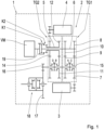
- This in figure 1 Transmission 2 shown is in an in figure 1 Motor vehicle 1, not shown, installed.
- the transmission 2 has a motor vehicle drive unit, such as an internal combustion engine VM, a first electric machine 3 and a second electric machine 4 .
- the transmission 2 has a first sub-transmission TG1 and a second sub-transmission TG2. Both sub-transmissions each have two wheel planes.
- the first sub-transmission TG1 is always connected to the first electric machine 3 in terms of drive technology
- the second sub-transmission TG2 is always connected to the second electric machine 4 in terms of drive technology.
- the transmission 2 has a clutch K2 and another clutch K1.
- the transmission 2 has a first shifting element B, a second shifting element A, a third shifting element D and a fourth shifting element C.
- the first switching element B and the third switching element D are designed as a double switching element.
- the second switching element A and the fourth switching element C are also designed as a double switching element.
- the other clutch K1 and clutch K2 are designed as double clutches.
- An output shaft 19 of the internal combustion engine VM can be connected in a torque-proof manner to a first transmission input shaft 6 by means of the other clutch K1.
- the output shaft 19 can be connected in a torque-proof manner to a second transmission input shaft 5 by means of the clutch K2.
- the second transmission input shaft 5 is arranged coaxially to the first transmission input shaft 6 and partially encloses it.
- the first sub-transmission TG1 has two gear planes, in each of which a gear pair is arranged.
- a gear wheel pair arranged in a first wheel plane has a first gear wheel 7 and a second gear wheel 8 which mesh with one another.
- a second gear wheel pair arranged in a second wheel plane has a third gear wheel 9 and a fourth gear wheel 10 which mesh with one another.
- the second gear wheel 8 and the fourth gear wheel 10 are each connected in a torque-proof manner to the first transmission input shaft 6 .
- the first electrical machine 3 is always operationally connected to the first gear wheel 7 by means of a traction mechanism in the form of a chain, for example.
- the second sub-transmission TG2 has two other gear planes, in each of which a different gear pair is arranged.
- a first other gear wheel pair arranged in a first gear plane has a first other gear wheel 11 and a second other gear wheel 12 which mesh with one another.
- a second other gear wheel pair arranged in a second other gear plane has a third other gear wheel 13 and a fourth other gear wheel 14 which mesh with one another.
- the second other gear 12 and the fourth other gear 14 are each connected to the second transmission input shaft 5 in a torque-proof manner.
- the second electrical machine 4 is always operationally connected to the fourth other gear wheel 14 by means of a traction mechanism in the form of a chain, for example.
- the first and second electrical machines 3, 4 are offset and/or arranged axially parallel to the first and/or second transmission input shaft 6, 5.
- the transmission 2 has a countershaft 15 .
- the countershaft 15 has an output gear 16 as a transmission output component, which is in engagement with a gear 17 of an axle differential 18 .
- the axle differential 18 is mechanically connected to vehicle wheels, not shown in the figure.
- the wheel shafts of the axle differential 18 run parallel to the first and second transmission input shafts 6, 5.
- the first gear wheel 7 can be connected in a torque-proof manner to the countershaft 15 by means of the fourth shifting element C.
- the third gear wheel 9 can be connected in a rotationally fixed manner to the countershaft 15 by means of the second shifting element A.
- the first other gear wheel 11 can be connected in a rotationally fixed manner to the countershaft 15 by means of the first shifting element B.
- the third other gear wheel 13 can be connected in a torque-proof manner to the countershaft 15 by means of the third shifting element D.
- the second shifting element A and the clutch K2 are closed and the remaining shifting elements and the other clutch K1 are open.
- the first electrical machine 3 is used to drive the motor vehicle 1 and the second electrical machine 4 is operated in generator mode.
- the second shifting element A is closed because the driving speed in series driving is low and therefore the first gear is better suited than the third gear resulting from a closed fourth shifting element C.
- the switching process described above takes place.
- the first shifting element B and the other clutch K1 are closed, as are the remaining shifting elements and the clutch K2 are open.
- Serial driving operation is also possible in this switching state, with the first electric machine 3 serving as a generator and the second electric machine 4 serving to drive the motor vehicle 1 .
- the first shifting element B is closed because at a low driving speed the second gear is better suited than the fourth gear resulting from a closed third shifting element D.
Landscapes
- Engineering & Computer Science (AREA)
- Mechanical Engineering (AREA)
- Chemical & Material Sciences (AREA)
- Combustion & Propulsion (AREA)
- Transportation (AREA)
- General Engineering & Computer Science (AREA)
- Automation & Control Theory (AREA)
- Electric Propulsion And Braking For Vehicles (AREA)
- Hybrid Electric Vehicles (AREA)
Description
- Die Erfindung betrifft ein Verfahren bei einem seriellen Fahrbetrieb eines Kraftfahrzeugs mit einem Getriebe, das eine erste elektrische Maschine, die in einem motorischen Betrieb zum Antreiben des Kraftfahrzeugs betrieben wird, und eine zweite elektrische Maschine aufweist, die in einem generatorischen Betrieb betrieben wird. Außerdem betrifft die Erfindung ein Getriebe, bei dem ein solches Verfahren ausgeübt wird.
- Aus dem Stand der Technik ist eine Vielzahl von Getrieben bekannt, die in Kraftfahrzeugen eingebaut sind und mittels denen ein serieller Fahrbetrieb des Kraftfahrzeugs realisiert werden kann. So offenbart
EP 1 610 038 B1 ein Doppelkupplungsgetriebe mit einer Doppelkupplung und zwei elektrischen Maschinen. Das Doppelkupplungsgetriebe ist derart ausgebildet, dass ein serieller Fahrbetrieb des Kraftfahrzeugs realisierbar ist. Zum Realisieren des seriellen Fahrbetriebs wird eine elektrische Maschine motorisch betrieben, um das Kraftfahrzeug anzutreiben, während die andere elektrische Maschine generatorisch betrieben wird, um die notwendige elektrische Energie zu liefern.DE 10 2006 036 758 A1 offenbart ein Doppelkupplungsgetriebe mit formschlüssiger Doppelkupplung und zwei elektrischen Maschinen. Weiterhin ist aus derWO 2016/199227 A1 ein Hybridfahrzeug mit einer Modusübergangsteuervorrichtung bekannt, die verhindert, dass ein zweites Stromerzeugungssystem während der Fahrt in einem Serien-HEV-Modus überhitzt. Ferner offenbart dieUS 2017/137016 A1 ein Motorsteuerverfahren, welches das Reduzieren der ersten von einem ersten Motor erzeugten Leistung und das Betreiben eines zweiten Motors umfasst, um eine zweite Leistung zu erzeugen, die der reduzierten ersten Leistung entspricht, wenn eine Temperatur des ersten Motors größer als eine erste Temperatur ist. - Ein Nachteil der aus dem Stand der Technik bekannten Getriebe ist, dass bei einem seriellen Fahrbetrieb mit einer langsamen Fahrgeschwindigkeit und hohem Fahrwiderstand, wie beispielsweise bei einem Berganstieg, die zum Antrieb des Kraftfahrzeugs verwendete elektrische Maschine thermisch stark belastet wird. Somit kann ein serieller Fahrbetrieb nur für eine begrenzte Zeit aufrechterhalten werden, weil die elektrische Maschine ansonsten überhitzen würde. Die andere elektrische Maschine, welche im generatorischen Betrieb betrieben wird, wird thermisch nicht überlastet, weil die Drehzahl der anderen elektrischen Maschine nicht an die Fahrgeschwindigkeit, sondern an die Verbrennungsmotordrehzahl gekoppelt ist.
- Die Aufgabe der Erfindung besteht somit darin, ein Verfahren anzugeben, mittels dem ein serieller Fahrbetrieb über einen längeren Zeitraum und bei einem hohen Fahrwiderstand realisiert werden kann.
- Die Aufgabe wird durch ein Verfahren der eingangs genannten Art gelöst, das dadurch gekennzeichnet ist, dass nach einem Erzeugen eines Umschaltsignals die erste elektrische Maschine von dem motorischen Betrieb in den generatorischen Betrieb umgeschaltet wird und die zweite elektrische Maschine von dem generatorischen Betrieb in den motorischen Betrieb zum Antreiben des Kraftfahrzeugs umgeschaltet wird.
- Erfindungsgemäß wurde erkannt, dass ein serieller Fahrbetrieb in Vorwärts- oder Rückwärtsrichtung bei einem hohen Fahrwiderstand über einen längeren Zeitraum realisiert werden kann, wenn die Funktionen der beiden elektrischen Maschinen vertauscht werden, bevor eine elektrische Maschine zu warm wird. Dies bedeutet, dass die elektrischen Maschinen wechselweise zum Antreiben des Kraftfahrzeugs eingesetzt werden. Somit kann verhindert werden, dass der serielle Fahrbetrieb unterbrochen wird, weil die im motorischen Betrieb betriebene elektrische Maschine zu warm wird. Ein weiterer Vorteil besteht darin, dass beide elektrische Maschinen gleichmäßig belastet werden, was sich vorteilhaft auf die Lebensdauer der elektrischen Maschinen auswirkt.
- Als serieller Fahrbetrieb eines Kraftfahrzeugs wird ein Fahrbetrieb verstanden, bei dem eine der beiden elektrischen Maschinen im generatorischen Betrieb betrieben und durch eine Antriebseinheit, wie beispielsweise einen Verbrennungsmotor, angetrieben wird und somit und die andere der beiden elektrischen Maschinen zum Antreiben des Kraftfahrzeugs dient, also im motorischen Betrieb betrieben wird. Beim seriellen Fahrbetrieb weist das Kraftfahrzeug üblicherweise eine geringe Fahrgeschwindigkeit auf.
- Die elektrische Maschine besteht zumindest aus einem Stator und einem drehbar gelagerten Rotor und ist in dem motorischen Betrieb dazu eingerichtet, elektrische Energie in mechanische Energie in Form von Drehzahl und Drehmoment zu wandeln, sowie in einem generatorischen Betrieb mechanische Energie in elektrische Energie in Form von Strom und Spannung zu wandeln.
- Bei einer besonderen Ausführung kann das Umschaltsignal erzeugt werden, wenn eine Temperatur der ersten elektrischen Maschine einen Schwellwert überschreitet oder wenn eine Temperatur der ersten elektrischen Maschine den Schwellwert überschreitet und eine Temperatur der zweiten elektrischen Maschine, insbesondere gleichzeitig, einen anderen Schwellwert unterschreitet. Eine derartige Erzeugung des Umschaltsignals bietet den Vorteil, dass die Umschaltung nur dann erfolgt, wenn sie unbedingt notwendig ist und somit so selten wie möglich. Dabei weist der Schwellwert einen größeren Wert auf als der andere Schwellwert. Der Schwellwert und/oder der andere Schwellwert können vorgegebenen sein und/oder in einem elektrischen Speicher hinterlegt sein.
- Alternativ oder zusätzlich kann das Umschaltsignal erzeugt werden, wenn eine Differenz zwischen der Temperatur der ersten elektrischen Maschine und der Temperatur der zweiten elektrischen Maschine einen weiteren Schwellwert überschreitet. Eine derartige Erzeugung des Umschaltsignals bietet den Vorteil, dass beide elektrischen Maschinen bezüglich ihrer Temperatur unterhalb des Schwellwerts betrieben werden. Der weitere Schwellwert kann vorgegeben und/oder in dem elektrischen Speicher hinterlegt sein.
- Die Temperatur der ersten elektrischen Maschine und der zweiten elektrischen Maschine kann jeweils durch einen Sensor oder mehrere Sensoren gemessen werden. Durch die Abhängigkeit des Umschaltsignals von der Temperatur der ersten elektrischen Maschine und/oder von der Temperatur der zweiten elektrischen Maschine kann auf einfache Weise verhindert werden, dass beim seriellen Fahrbetrieb die erste elektrische Maschine und/oder die zweite elektrische Maschine überhitzt.
- Bei einer besonderen Ausführung kann die erste elektrische Maschine von dem motorischen Betrieb in den generatorischen Betrieb ohne Zugkraftunterbrechung umgeschaltet werden. Darüber hinaus kann die zweite elektrische Maschine von dem generatorischen Betrieb in den motorischen Betrieb ohne Zugkraftunterbrechung umgeschaltet werden. Ein derartiger Umschaltvorgang bietet sich aus Komfortgründen an. Insbesondere kann die Umschaltung erfolgen, ohne dass die Fahrzeuginsassen diese bemerken.
- Das Kraftfahrzeug kann einen elektrischen Energiespeicher, wie beispielsweise eine elektrische Batterie, aufweisen. Der elektrische Energiespeicher kann durch die im generatorischen Betrieb betriebene erste elektrische Maschine oder durch die im generatorischen Betrieb betriebene zweite elektrische Maschine aufgeladen werden. Dadurch kann während des seriellen Fahrbetriebs ein Aufladen des elektrischen Energiespeichers auf einfache Weise erfolgen. Dies führt dazu, dass der elektrische Energiespeicher kleiner dimensioniert werden kann als elektrische Energiespeicher, die nicht mittels einer im generatorischen Betrieb betriebenen elektrischen Maschine aufgeladen werden.
- Beim seriellen Fahrbetrieb kann wahlweise die erste elektrische Maschine im motorischen Betrieb und die zweite elektrische Maschine im generatorischen Betrieb oder die erste elektrische Maschine im generatorischen Betrieb und die zweite elektrische Maschine im motorischen Betrieb betrieben werden. Somit ist jederzeit sichergestellt, dass eine elektrische Maschine zum Antreiben des Kraftfahrzeugs dient und die andere elektrische Maschine zum Aufladen des elektrischen Energiespeichers eingesetzt wird.
- Bei einer besonderen Ausführung können zum Umschalten der zweiten elektrischen Maschine von dem generatorischen Betrieb in den motorischen Betrieb folgende Schritte in nachfolgend genannter Reihenfolge durchgeführt werden.
- a. Durchführen eines Lastabbaus an einem Verbrennungsmotor und der zweiten elektrischen Maschine, um eine Kupplung des Getriebes lastfrei zu stellen,
- b. Öffnen der Kupplung,
- c. Synchronisieren eines ersten Schaltelements des Getriebes,
- d. Schließen des ersten Schaltelements, so dass eine triebtechnische Verbindung zwischen der zweiten elektrischen Maschine und einem Achsdifferential besteht,
- e. Durchführen eines Lastabbaus an der ersten elektrischen Maschine und eines Lastaufbaus an der zweiten elektrischen Maschine, um ein zweites Schaltelement des Getriebes lastfrei zu stellen,
- f. Öffnen des zweiten Schaltelements,
- g. Synchronisieren von einer anderen Kupplung,
- h. Schließen der anderen Kupplung, so dass eine triebtechnische Verbindung zwischen dem Verbrennungsmotor und der ersten elektrischen Maschine besteht,
- i. Durchführen eines Lastaufbaus an dem Verbrennungsmotor und der ersten elektrischen Maschine, wobei die erste elektrische Maschine in einem generatorischen Betrieb betrieben wird.
- Der Lastabbau an dem Verbrennungsmotor und der zweiten elektrischen Maschine können gleichzeitig erfolgen. Nach erfolgtem Lastabbau muss der elektrische Energiespeicher die Versorgung der im motorischen Betrieb betriebenen ersten elektrischen Maschine mit elektrischer Energie übernehmen. Durch den Lastabbau an der zweiten elektrischen Maschine wird auf einfache Weise verhindert, dass der Verbrennungsmotor durch die zweite elektrische Maschine abgewürgt wird.
- Das erste Schaltelement wird derart synchronisiert, dass eine Drehzahl eines Schaltelementbestandteils mit einer Drehzahl eines anderen Schaltelementbestandteils übereinstimmt, so dass im nächsten Schritt das erste Schaltelement geschlossen werden kann und somit die beiden Schaltelementbestandteile drehfest miteinander verbunden sind. Insbesondere kann die Drehzahl eines mit der zweiten elektrischen Maschine triebtechnisch verbundenen Zahnrads an die Drehzahl einer ein Abtriebszahnrad aufweisenden Vorgelegewelle angepasst werden.
- Der Lastabbau an der ersten elektrischen Maschine und der Lastaufbau an der zweiten elektrischen Maschine können gleichzeitig durchgeführt werden. Dadurch kann auf einfache Weise sichergestellt werden, dass das Antriebsdrehmoment konstant bleibt und/oder das Umschalten ohne Zugkraftunterbrechung erfolgt. Insbesondere kann ausschließlich die im motorischen Betrieb betriebene zweite elektrische Maschine zum Antreiben des Kraftfahrzeugs dienen.
- Der Lastaufbau an dem Verbrennungsmotor und der ersten elektrischen Maschine kann gleichzeitig durchgeführt werden. Nach erfolgtem Lastabbau wird der elektrische Energiespeicher entlastet. Insbesondere wird ab diesem Schritt der elektrische Energiespeicher durch die im generatorischen Betrieb betriebene erste elektrische Maschine aufgeladen.
- Bei einer besonderen Ausführung kann nach dem Erzeugen eines weiteren Umschaltsignals die erste elektrische Maschine in dem motorischen Betrieb betrieben werden und die zweite elektrische Maschine kann in dem generatorischen Betrieb betrieben werden. Im Ergebnis kann abwechselnd die erste elektrische Maschine oder die zweite elektrische Maschine in dem motorischen Betrieb betrieben werden. Dadurch wird ein serieller Fahrbetrieb mit hohem Fahrwiderstand über einen längeren Zeitraum möglich, ohne dass die Gefahr besteht, dass die erste elektrische Maschine oder die zweite elektrische Maschine überhitzt.
- Das weitere Umschaltsignal kann erzeugt werden, wenn die Temperatur der zweiten elektrischen Maschine einen Schwellenwert überschreitet oder wenn die Temperatur der zweiten elektrischen Maschine einen Schwellwert überschreitet und eine Temperatur der ersten elektrischen Maschine, insbesondere gleichzeitig, einen anderen Schwellwert unterschreitet. Dabei weist der Schwellwert einen größeren Wert auf, als der andere Schwellwert. Alternativ oder zusätzlich kann das Umschaltsignal erzeugt werden, wenn eine Differenz zwischen der Temperatur der zweiten elektrischen Maschine und der Temperatur der ersten elektrischen Maschine einen weiteren Schwellwert überschreitet.
- Darüber hinaus kann das Umschaltsignal erst dann erzeugt werden, wenn festgestellt wird, dass der elektrische Energiespeicher derart aufgeladen ist, dass ausreichend elektrische Energie für die Umschaltung zur Verfügung steht. Insbesondere kann geprüft werden, ob genügend Kapazität für die Umschaltung zur Verfügung steht. Der serielle Fahrbetrieb kann genutzt werden, um den elektrischen Energiespeicher soweit aufzuladen, dass für den Umschaltvorgang genügend elektrische Energie zur Verfügung steht. Die für den Umschaltvorgang benötigte Energiemenge ist nicht hoch, weil der Umschaltvorgang kurz ist und beispielsweise zwei Sekunden dauert.
- Zum Umschalten der ersten elektrischen Maschine von dem generatorischen Betrieb in den motorischen Betrieb können folgende Schritte in nachfolgend genannter Reihenfolge durchgeführt werden:
- a. Durchführen eines Lastabbaus an einem Verbrennungsmotor und der ersten elektrischen Maschine, um eine andere Kupplung des Getriebes lastfrei zu stellen,
- b. Öffnen der anderen Kupplung,
- c. Synchronisieren eines zweiten Schaltelements des Getriebes,
- d. Schließen des zweiten Schaltelements, so dass eine triebtechnische Verbindung zwischen der ersten elektrischen Maschine und einem Achsdifferential besteht,
- e. Durchführen eines Lastabbaus an der zweiten elektrischen Maschine und eines Lastaufbaus an der ersten elektrischen Maschine, um ein erstes Schaltelement des Getriebes lastfrei zu stellen,
- f. Öffnen des ersten Schaltelements,
- g. Synchronisieren einer Kupplung,
- h. Schließen der Kupplung, so dass eine triebtechnische Verbindung zwischen dem Verbrennungsmotor und der zweiten elektrischen Maschine besteht,
- i. Durchführen eines Lastaufbaus an dem Verbrennungsmotor und der zweiten elektrischen Maschine, wobei die zweite elektrische Maschine im generatorischen Betrieb betrieben wird.
- Der Lastabbau an dem Verbrennungsmotor und der ersten elektrischen Maschine können gleichzeitig erfolgen. Nach erfolgtem Lastabbau muss der elektrische Energiespeicher die Versorgung der zweiten elektrischen Maschine mit elektrischer Energie übernehmen. Durch den erfolgten Lastabbau an der ersten elektrischen Maschine wird auf einfache Weise verhindert, dass der Verbrennungsmotor durch die erste elektrische Maschine abgewürgt wird.
- Das zweite Schaltelement wird derart synchronisiert, dass eine Drehzahl eines Schaltelementbestandteils mit einer Drehzahl eines anderen Schaltelementbestandteils übereinstimmt, so dass im nächsten Schritt das zweite Schaltelement geschlossen werden kann und somit die beiden Schaltelementbestandteile miteinander drehfest verbunden sind. Insbesondere kann die Drehzahl eines mit der ersten elektrischen Maschine triebtechnisch verbundenen Zahnrads an die Drehzahl der Vorgelegewelle angepasst werden.
- Der Lastabbau an der zweiten elektrischen Maschine und der Lastaufbau an der ersten elektrischen Maschine können gleichzeitig durchgeführt werden. Dadurch kann auf einfache Weise sichergestellt werden, dass das Antriebsdrehmoment konstant bleibt und/oder das Umschalten ohne Zugkraftunterbrechung erfolgt. Insbesondere kann ausschließlich die im motorischen Betrieb betriebene erste elektrische Maschine zum Antreiben des Kraftfahrzeugs dienen.
- Der Lastaufbau an dem Verbrennungsmotor und der zweiten elektrischen Maschine kann gleichzeitig durchgeführt werden. Nach erfolgtem Lastabbau wird der elektrische Energiespeicher entlastet. Insbesondere wird ab diesem Schritt der elektrische Energiespeicher durch die im generatorischen Betrieb betriebene zweite elektrische Maschine aufgeladen.
- Die Kupplung und die andere Kupplung dienen jeweils zum triebtechnischen Verbinden des Getriebes mit der Kraftfahrzeugantriebseinheit, wie dem Verbrennungsmotor. Insbesondere kann während der oben beschriebenen Schritte c bis h der Verbrennungsmotor in einem Leerlauf betrieben werden. Ein Abschalten des Verbrennungsmotors lohnt sich nicht, weil die Umschaltung in einem kurzen Zeitraum durchgeführt werden kann.
- Die erste elektrische Maschine kann mittels der anderen Kupplung mit dem Verbrennungsmotor triebtechnisch verbindbar sein. Darüber hinaus kann die zweite elektrische Maschine mittels der Kupplung mit dem Verbrennungsmotor triebtechnisch verbindbar sein.
- Dabei kann das zweite Schaltelement mittels einer Drehzahlregelung der ersten elektrischen Maschine synchronisiert werden. Dazu wird ein Schaltelementbestandteil des zweiten Schaltelements mittels der ersten elektrischen Maschine auf die gewünschte Drehzahl gebracht. Das erste Schaltelement kann mittels einer Drehzahlregelung der zweiten elektrischen Maschine synchronisiert werden. Dazu wird ein Schaltelementbestandteil des ersten Schaltelements mittels der zweiten elektrischen Maschine auf die gewünschte Drehzahl gebracht.
- Bei den oben beschriebenen Schritten b bis h wird die im motorischen Betrieb betriebene erste elektrische Maschine oder die im motorischen Betrieb betriebene zweite elektrische Maschine mit elektrischer Energie aus dem elektrischen Energiespeicher versorgt. Mittels einer Betriebsstrategie wird sichergestellt, dass der elektrische Energiespeicher vor einem Umschalten ausreichend elektrische Energie aufweist, um die jeweilige im motorisch betriebene elektrische Maschine während des Umschaltvorgangs mit elektrischer Energie zu versorgen.
- Von besonderem Vorteil ist ein Getriebe, bei dem ein erfindungsgemäßes Verfahren ausgeführt wird. Das Getriebe kann ein Automatgetriebe sein, das mehrere Gänge aufweist. Dabei kann das Getriebe wenigstens vier, insbesondere genau vier, Gänge für einen seriellen Fahrbetrieb aufweisen. Ein erster Gang kann durch Schließen des zweiten Schaltelements realisiert werden, wobei die restlichen Schaltelemente geöffnet sind. Zum Realisieren des ersten Gangs ist zusätzlich die andere Kupplung geschlossen und die Kupplung geöffnet. Darüber hinaus kann durch Schließen des ersten Schaltelements ein zweiter Gang realisiert werden, wobei die restlichen Schaltelemente geöffnet sind. Zum Realisieren des zweiten Gangs ist zusätzlich die Kupplung geschlossen und die andere Kupplung geöffnet. Die einzelnen Gänge unterscheiden sich in ihrer Übersetzung zwischen einer ersten bzw. zweiten Getriebeeingangswelle und einem Getriebeausgangsbauteil, wie dem zuvor erwähnten Abtriebszahnrad, voneinander. Beim erfindungsgemäßen Verfahren kann beim Umschaltvorgang abwechselnd zwischen dem ersten Gang und dem zweiten Gang gewechselt werden.
- Unter einer Welle ist nicht ausschließlich ein beispielsweise zylindrisches, drehbar gelagertes Maschinenelement zur Übertragung von Drehmomenten zu verstehen, sondern vielmehr sind hierunter auch allgemeine Verbindungselemente zu verstehen, die einzelne Bauteile oder Elemente miteinander verbinden, insbesondere Verbindungselemente, die mehrere Elemente drehfest miteinander verbinden.
- Das Getriebe kann auch derart ausgebildet sein, dass ein rein elektrischer Fahrbetrieb möglich ist. Zum Realisieren des rein elektrischen Fahrbetriebs wird die Kupplung und/oder die andere Kupplung nicht geschlossen, während hingegen wenigstens ein Schaltelement, insbesondere genau ein, Schaltelement geschlossen wird. Der Antrieb des Kraftfahrzeugs erfolgt mittels der ersten elektrischen Maschine und/oder der zweiten elektrischen Maschine.
- Das Getriebe kann als Doppelkupplungsgetriebe ausgebildet sein. Bei diesem Fall bilden die Kupplung und die andere Kupplung eine Doppelkupplung. Dabei kann die Doppelkupplung eine formschlüssige oder eine reibschlüssige Doppelkupplung sein. Das Getriebe kann auch derart ausgebildet sein, dass es sich für einen Front-Quereinbau eignet.
- Darüber hinaus kann das Getriebe wenigstens zwei, insbesondere genau zwei, Teilgetriebe aufweisen. Dabei ist ein erstes Teilgetriebe mit der ersten elektrischen Maschine stets triebtechnisch verbunden. Ein zweites Teilgetriebe ist mit der zweiten elektrischen Maschine stets triebtechnisch verbunden. Jedes der Teilgetriebe kann eine oder mehrere Radebenen aufweisen. Die Anbindung der elektrischen Maschine an die jeweiligen Teilgetriebe kann einstufig oder mehrstufig erfolgen. Dabei kann die Anbindung als Stirnradanbindung ausgeführt sein. Dabei kann die Anbindung derart erfolgen, dass die Vorübersetzungen der ersten elektrischen Maschine und der zweiten elektrischen Maschine unterschiedlich sind.
- Die Kraftfahrzeugantriebseinheit ist mittels der anderen Kupplung mit dem ersten Teilgetriebe triebtechnisch verbindbar und mittels der Kupplung mit dem zweiten Teilgetriebe triebtechnisch verbindbar. Zum Realisieren eines Gangs wird jeweils eines der Teilgetriebe mit dem Getriebeausgangsbauteil triebtechnisch verbunden. Dabei werden benachbarte Gänge durch abwechselndes triebtechnisches Verbinden des ersten Teilgetriebes und des zweiten Teilgetriebes mit dem Getriebeausgangsbauteil realisiert. Dem ersten Teilgetriebe können der erste und ein dritter Gang zugeordnet sein. Dem zweiten Teilgetriebe können ein zweiter und ein vierter Gang zugeordnet sein. Von besonderem Vorteil ist der Einsatz des erfindungsgemäßen Getriebes in einem Kraftfahrzeug.
- In der Figur ist der Erfindungsgegenstand schematisch dargestellt und wird nachfolgend beschrieben. Dabei zeigt:
- Figur 1
- eine Darstellung eines Getriebes, bei dem das erfindungsgemäße Verfahren ausgeführt werden kann.
- Das in
Figur 1 gezeigte Getriebe 2 ist in einem inFigur 1 nicht näher dargestellten Kraftfahrzeug 1 eingebaut. Das Getriebe 2 weist eine Kraftfahrzeugantriebseinheit, wie beispielsweise einen Verbrennungsmotor VM, eine erste elektrische Maschine 3 und eine zweite elektrische Maschine 4 auf. Darüber hinaus weist das Getriebe 2 ein erstes Teilgetriebe TG1 und ein zweites Teilgetriebe TG2 auf. Beide Teilgetriebe weisen jeweils zwei Radebenen auf. Dabei ist das erste Teilgetriebe TG1 mit der ersten elektrischen Maschine 3 stets triebtechnisch verbunden und das zweite Teilgetriebe TG2 ist mit der zweiten elektrischen Maschine 4 stets triebtechnisch verbunden. - Das Getriebe 2 weist eine Kupplung K2 und eine andere Kupplung K1 auf. Darüber hinaus weist das Getriebe 2 ein erstes Schaltelement B, ein zweites Schaltelement A, ein drittes Schaltelement D und ein viertes Schaltelement C auf. Das erste Schaltelement B und das dritte Schaltelement D sind als Doppelschaltelement ausgeführt. Das zweite Schaltelement A und das vierte Schaltelement C sind ebenfalls als Doppelschaltelement ausgeführt. Die andere Kupplung K1 und die Kupplung K2 sind als Doppelkupplung ausgeführt.
- Eine Abtriebswelle 19 des Verbrennungsmotors VM ist mittels der anderen Kupplung K1 mit einer ersten Getriebeeingangswelle 6 drehfest verbindbar. Darüber hinaus ist die Abtriebswelle 19 mittels der Kupplung K2 mit einer zweiten Getriebeeingangswelle 5 drehfest verbindbar. Die zweite Getriebeeingangswelle 5 ist koaxial zu der ersten Getriebeeingangswelle 6 angeordnet und umschließt diese teilweise.
- Das erste Teilgetriebe TG1 weist zwei Radebenen auf, in denen jeweils ein Zahnradpaar angeordnet sind. So weist ein in einer ersten Radebene angeordnetes Zahnradpaar ein erstes Zahnrad 7 und ein zweites Zahnrad 8 auf, die miteinander in Eingriff stehen. Ein in einer zweiten Radebene angeordnetes zweites Zahnradpaar weist ein drittes Zahnrad 9 und ein viertes Zahnrad 10 auf, die miteinander in Eingriff stehen. Das zweite Zahnrad 8 und das vierte Zahnrad 10 sind mit der ersten Getriebeeingangswelle 6 jeweils drehfest verbunden. Die erste elektrische Maschine 3 ist mittels eines Zugmittels in Form von beispielsweise einer Kette mit dem ersten Zahnrad 7 stets triebtechnisch verbunden.
- Das zweite Teilgetriebe TG2 weist zwei andere Radebenen auf, in denen jeweils ein anderes Zahnradpaar angeordnet ist. So weist ein in einer ersten Radebene angeordnetes erstes anderes Zahnradpaar ein erstes anderes Zahnrad 11 und ein zweites anderes Zahnrad 12 auf, die miteinander in Eingriff stehen. Ein in einer zweiten anderen Radebene angeordnetes zweites anderes Zahnradpaar weist ein drittes anderes Zahnrad 13 und ein viertes anderes Zahnrad 14 auf, die miteinander in Eingriff stehen. Das zweite andere Zahnrad 12 und das vierte andere Zahnrad 14 sind mit der zweiten Getriebeeingangswelle 5 jeweils drehfest verbunden.
- Die zweite elektrische Maschine 4 ist mittels eines Zugmittels in Form von beispielsweise einer Kette mit dem vierten anderen Zahnrad 14 stets triebtechnisch verbunden. Die erste und zweite elektrische Maschine 3, 4 sind achsversetzt und/oder achsparallel zu der ersten und/oder zweiten Getriebeeingangswelle 6, 5 angeordnet.
- Das Getriebe 2 weist eine Vorgelegewelle 15 auf. Die Vorgelegewelle 15 weist als Getriebeausgangsbauteil ein Abtriebszahnrad 16 auf, das mit einem Zahnrad 17 eines Achsdifferentials 18 in Eingriff ist. Das Achsdifferential 18 ist mit in der Figur nicht dargestellten Fahrzeugrädern triebtechnisch verbunden. Dabei verlaufen Radwellen des Achsdifferentials 18 parallel zu der ersten und zweiten Getriebeeingangswelle 6, 5.
- Das erste Zahnrad 7 ist mittels des vierten Schaltelements C mit der Vorgelegewelle 15 drehfest verbindbar. Das dritte Zahnrad 9 ist mittels des zweiten Schaltelements A mit der Vorgelegewelle 15 drehfest verbindbar. Das erste andere Zahnrad 11 ist mittels des ersten Schaltelements B mit der Vorgelegewelle 15 drehfest verbindbar. Das dritte andere Zahnrad 13 ist mittels des dritten Schaltelements D mit der Vorgelegewelle 15 drehfest verbindbar.
- Mit dem Getriebe 2 ist ein rein elektrischer Fahrbetrieb mittels beispielsweise der ersten elektrischen Maschine 3 möglich. Beim rein elektrischen Fahrbetrieb ist das zweite Schaltelement A oder das vierte Schaltelement C geschlossen und die beiden Kupplungen K1, K2 sind geöffnet. Dabei wird beim geschlossenen zweiten Schaltelement A ein erster Gang und beim geschlossenen vierten Schaltelement C ein dritter Gang realisiert. Darüber hinaus ist mittels des Getriebes 2 ein rein elektrischer Fahrbetrieb mittels der zweiten elektrischen Maschine 4 möglich. Beim rein elektrischen Fahrbetrieb mittels der zweiten elektrischen Maschine 4 ist das erste Schaltelement B oder das dritte Schaltelement D geschlossen und die beiden Kupplungen K1, K2 sind geöffnet. Dabei wird beim geschlossenen ersten Schaltelement B ein zweiter Gang und beim geschlossenen dritten Schaltelement D ein vierter Gang realisiert.
- Beim seriellen Fahrbetrieb sind das zweite Schaltelement A und die Kupplung K2 geschlossen und die restlichen Schaltelemente und die andere Kupplung K1 sind geöffnet. Bei diesem Schaltzustand dient die erste elektrische Maschine 3 zum Antreiben des Kraftfahrzeugs 1 und die zweite elektrische Maschine 4 wird im generatorischen Betrieb betrieben. Das zweite Schaltelement A ist geschlossen, weil beim seriellen Fahrbetrieb eine geringe Fahrgeschwindigkeit vorliegt und daher der erste Gang besser geeignet ist als der bei einem geschlossenen vierten Schaltelement C resultierende dritte Gang.
- Sobald ermittelt wird, dass beispielsweise die Temperatur der ersten elektrischen Maschine 3 einen Schwellwert überschreitet, erfolgt der oben beschriebene Umschaltvorgang. Nach dem Umschaltvorgang sind das erste Schaltelement B und die andere Kupplung K1 geschlossen und die restlichen Schaltelemente und die Kupplung K2 sind geöffnet. Auch bei diesem Schaltzustand ist ein serieller Fahrbetrieb möglich, wobei die erste elektrische Maschine 3 als Generator und die zweite elektrische Maschine 4 zum Antreiben des Kraftfahrzeugs 1 dient. Das erste Schaltelement B ist geschlossen, weil bei einer geringen Fahrgeschwindigkeit der zweite Gang besser geeignet ist als der bei einem geschlossenen dritten Schaltelement D resultierende vierte Gang.
-
- 1
- Kraftfahrzeug
- 2
- Getriebe
- 3
- erste elektrische Maschine
- 4
- zweite elektrische Maschine
- 5
- zweite Getriebeeingangswelle
- 6
- erste Getriebeeingangswelle
- 7
- erstes Zahnrad
- 8
- zweites Zahnrad
- 9
- drittes Zahnrad
- 10
- viertes Zahnrad
- 11
- erstes anderes Zahnrad
- 12
- zweites anderes Zahnrad
- 13
- drittes anderes Zahnrad
- 14
- viertes anderes Zahnrad
- 15
- Vorgelegewelle
- 16
- Abtriebszahnrad
- 17
- Zahnrad
- 18
- Achsdifferential
- 19
- Abtriebswelle
- A
- zweites Schaltelement
- B
- erstes Schaltelement
- C
- viertes Schaltelement
- D
- drittes Schaltelement
- K1
- andere Kupplung
- K2
- Kupplung
- VM
- Verbrennungsmotor
- TG1
- erstes Teilgetriebe
- TG2
- zweites Teilgetriebe
Claims (15)
- Verfahren bei einem seriellen Fahrbetrieb eines Kraftfahrzeugs (1) mit einem Getriebe (2), das eine erste elektrische Maschine (3), die in einem motorischen Betrieb zum Antreiben des Kraftfahrzeugs (1) betrieben wird, und eine zweite elektrische Maschine (4) aufweist, die in einem generatorischen Betrieb betrieben wird, dadurch gekennzeichnet, dass nach einem Erzeugen eines Umschaltsignals die erste elektrische Maschine (3) von dem motorischen Betrieb in den generatorischen Betrieb umgeschaltet wird und die zweite elektrische Maschine (4) von dem generatorischen Betrieb in den motorischen Betrieb zum Antreiben des Kraftfahrzeugs (1) umgeschaltet wird.
- Verfahren nach Anspruch 1, dadurch gekennzeichnet, dass das Umschaltsignal erzeugt wird, wenna. eine Temperatur der ersten elektrischen Maschine (3) einen Schwellwert überschreitet oder wennb. eine Temperatur der ersten elektrischen Maschine (3) einen Schwellwert überschreitet und eine Temperatur der zweiten elektrischen Maschine (4) einen anderen Schwellwert unterschreitet.
- Verfahren nach Anspruch 1 oder 2, dadurch gekennzeichnet, dass das Umschaltsignal erzeugt wird, wenn eine Differenz zwischen einer Temperatur der ersten elektrischen Maschine (3) und einer Temperatur der zweiten elektrischen Maschine (4) einen weiteren Schwellwert überschreitet.
- Verfahren nach einem der Ansprüche 1 bis 3, wobei das Getriebe eine Doppelkupplung (K1, K2) umfasst, dadurch gekennzeichnet, dassa. die erste elektrische Maschine (3) mittels der Doppelkupplung (K1, K2) von dem motorischen Betrieb in den generatorischen Betrieb ohne Zugkraftunterbrechung umgeschaltet wird und/oder dassb. die zweite elektrische Maschine (4) mittels der Doppelkupplung (K1, K2) von dem generatorischen Betrieb in den motorischen Betrieb ohne Zugkraftunterbrechung umgeschaltet wird.
- Verfahren nach einem der Ansprüche 1 bis 4, dadurch gekennzeichnet, dassa. ein elektrischer Energiespeicher durch die im generatorischen Betrieb betriebene erste elektrische Maschine (3) oder durch die im generatorischen Betrieb betriebene zweite elektrischer Maschine (4) aufgeladen wird und/oder dassb. wahlweise die erste elektrische Maschine (3) im motorischen Betrieb und die zweite elektrische Maschine (4) im generatorischen Betrieb oder die erste elektrische Maschine (3) im generatorischen Betrieb und die zweite elektrische Maschine (4) im motorischen Betrieb betrieben wird.
- Verfahren nach einem der Ansprüche 1 bis 5, dadurch gekennzeichnet, dass zum Umschalten der zweiten elektrischen Maschine (4) von dem generatorischen Betrieb in den motorischen Betrieb folgende Schritte in nachfolgend genannter Reihenfolge durchgeführt werden:a. Durchführen eines Lastabbaus an einem Verbrennungsmotor (VM) und der zweiten elektrischen Maschine (4), um eine Kupplung (K2) des Getriebes (2) lastfrei zu stellen,b. Öffnen der Kupplung (K2),c. Synchronisieren eines ersten Schaltelements (B) des Getriebes (2),d. Schließen des ersten Schaltelements (B), so dass eine triebtechnische Verbindung zwischen der zweiten elektrischen Maschine (4) und einem Achsdifferential (18) besteht,e. Durchführen eines Lastabbaus an der ersten elektrischen Maschine (3) und eines Lastaufbaus an der zweiten elektrischen Maschine (4), um ein zweites Schaltelement (A) des Getriebes (2) lastfrei zu stellen,f. Öffnen des zweiten Schaltelements (A),g. Synchronisieren von einer anderen Kupplung (K1),h. Schließen der anderen Kupplung (K1), so dass eine triebtechnische Verbindung zwischen dem Verbrennungsmotor (VM) und der ersten elektrischen Maschine (3) besteht,i. Durchführen eines Lastaufbaus an dem Verbrennungsmotor (VM) und der ersten elektrischen Maschine (3), wobei die erste elektrische Maschine (3) in einem generatorischen Betrieb betrieben wird.
- Verfahren nach einem der Ansprüche 1 bis 6, dadurch gekennzeichnet, dass nach dem Erzeugen eines weiteren Umschaltsignals die erste elektrische Maschine (3) in dem motorischen Betrieb betrieben wird und die zweite elektrische Maschine (4) in dem generatorischen Betrieb betrieben wird.
- Verfahren nach Anspruch 7, dadurch gekennzeichnet, dass das weitere Umschaltsignal erzeugt wird, wenna. eine Temperatur der zweiten elektrischen Maschine (4) einen Schwellwert überschreitet oder wennb. eine Temperatur der zweiten elektrischen Maschine (4) einen Schwellwert überschreitet und eine Temperatur der ersten elektrischen Maschinen (3) einen anderen Schwellwert unterschreitet.
- Verfahren nach Anspruch 7 oder 8, dadurch gekennzeichnet, dass das weitere Umschaltsignal erzeugt wird, wenn eine Differenz zwischen einer Temperatur der zweiten elektrischen Maschine (4) und einer Temperatur der ersten elektrischen Maschine (3) einen weiteren Schwellwert überschreitet.
- Verfahren nach einem der Ansprüche 7 bis 9, dadurch gekennzeichnet, dass zum Umschalten der ersten elektrischen Maschine (3) von dem generatorischen Betrieb in den motorischen Betrieb folgende Schritte in nachfolgend genannter Reihenfolge durchgeführt werden:a. Durchführen eines Lastabbaus an einem Verbrennungsmotor (VM) und der ersten elektrischen Maschine (3), um eine andere Kupplung (K1) des Getriebes (2) lastfrei zu stellen,b. Öffnen der anderen Kupplung (K1),c. Synchronisieren eines zweiten Schaltelements (A) des Getriebes (2),d. Schließen des zweiten Schaltelements (A), so dass eine triebtechnische Verbindung zwischen der ersten elektrischen Maschine (3) und einem Achsdifferential (18) besteht,e. Durchführen eines Lastabbaus an der zweiten elektrischen Maschine (4) und eines Lastaufbaus an der ersten elektrischen Maschine (3), um ein erstes Schaltelement (B) des Getriebes (2) lastfrei zu stellen,f. Öffnen des ersten Schaltelements (B),g. Synchronisieren einer Kupplung (K2),h. Schließen der Kupplung (K2), so dass eine triebtechnische Verbindung zwischen dem Verbrennungsmotor (VM) und der zweiten elektrischen Maschine (4) besteht,i. Durchführen eines Lastaufbaus an dem Verbrennungsmotor (VM) und der zweiten elektrischen Maschine (4), wobei die zweite elektrische Maschine (4) im generatorischen Betrieb betrieben wird.
- Verfahren nach Anspruch 6 bis 10, dadurch gekennzeichnet, dassa. der Verbrennungsmotor (VM) während der Schritte c bis h im Leerlauf betrieben wird und/oder dassb. bei den Schritten b bis h die im motorischen Betrieb betriebene erste elektrische Maschine (3) oder die im motorischen Betrieb betriebene zweite elektrische Maschine (4) mit elektrischer Energie aus einem elektrischen Energiespeicher versorgt wird.
- Verfahren nach einem der Ansprüche 6 bis 11, dadurch gekennzeichnet, dassa. durch Schließen des ersten Schaltelements (B) ein zweiter Gang realisiert wird und/oder dassb. durch Schließen des zweiten Schaltelements (A) ein erster Gang realisiert wird.
- Verfahren nach einem der Ansprüche 6 bis 12 dadurch gekennzeichnet, dassa. das Synchronisieren des zweiten Schaltelements (A) mittels einer Drehzahlregelung der ersten elektrischen Maschine (3) durchgeführt wird und/oder dassb. das Synchronisieren des ersten Schaltelements (B) mittels einer Drehzahlregelung der zweiten elektrischen Maschine (4) durchgeführt wird.
- Getriebe (2), das einen Verbrennungsmotor (VM), eine erste elektrische Maschine (3), eine zweite elektrische Maschine (4), eine Kupplung (K2) und eine andere Kupplung (K1) umfasst, wobei das Getriebe derart ausgebildet ist, ein Verfahren nach einem der Ansprüche 1 bis 13 auszuführen.
- Getriebe (2) nach Anspruch 14, dadurch gekennzeichnet, dassa. die erste elektrische Maschine (3) mittels der anderen Kupplung (K1) mit dem Verbrennungsmotor (VM) triebtechnisch verbindbar ist und/oder dassb. die zweite elektrische Maschine (4) mittels der Kupplung (K2) mit dem Verbrennungsmotor (VM) triebtechnisch verbindbar ist.
Applications Claiming Priority (2)
| Application Number | Priority Date | Filing Date | Title |
|---|---|---|---|
| DE102017223168.8A DE102017223168A1 (de) | 2017-12-19 | 2017-12-19 | Verfahren bei einem seriellen Fahrbetrieb eines Kraftfahrzeugs |
| PCT/EP2018/081603 WO2019120797A1 (de) | 2017-12-19 | 2018-11-16 | Verfahren bei einem seriellen fahrbetrieb eines kraftfahrzeugs |
Publications (2)
| Publication Number | Publication Date |
|---|---|
| EP3727919A1 EP3727919A1 (de) | 2020-10-28 |
| EP3727919B1 true EP3727919B1 (de) | 2023-05-03 |
Family
ID=64402202
Family Applications (1)
| Application Number | Title | Priority Date | Filing Date |
|---|---|---|---|
| EP18807041.1A Active EP3727919B1 (de) | 2017-12-19 | 2018-11-16 | Verfahren bei einem seriellen fahrbetrieb eines kraftfahrzeugs |
Country Status (5)
| Country | Link |
|---|---|
| US (1) | US11590960B2 (de) |
| EP (1) | EP3727919B1 (de) |
| CN (1) | CN111278672B (de) |
| DE (1) | DE102017223168A1 (de) |
| WO (1) | WO2019120797A1 (de) |
Families Citing this family (9)
| Publication number | Priority date | Publication date | Assignee | Title |
|---|---|---|---|---|
| DE102019202953A1 (de) * | 2019-03-05 | 2020-09-10 | Zf Friedrichshafen Ag | Hybrid-Getriebeeinrichtung sowie Kraftfahrzeug |
| DE102019202955A1 (de) * | 2019-03-05 | 2020-09-10 | Zf Friedrichshafen Ag | Hybrid-Getriebeeinrichtung sowie Kraftfahrzeug |
| DE102019203486A1 (de) * | 2019-03-14 | 2020-09-17 | Zf Friedrichshafen Ag | Hybrid-Getriebeeinrichtung sowie Kraftfahrzeug |
| DE102019209931B4 (de) * | 2019-07-05 | 2024-11-21 | Zf Friedrichshafen Ag | Lastschaltbares Hybridgetriebe |
| CN110901366B (zh) * | 2019-12-26 | 2024-11-01 | 株洲齿轮有限责任公司 | 混合动力变速箱、混合动力驱动系统及汽车 |
| DE102020129821A1 (de) | 2020-11-12 | 2022-05-12 | Bayerische Motoren Werke Aktiengesellschaft | Hybridantriebsvorrichtung für einen zugkraftunterbrechungsfreien Antrieb und Kraftfahrzeug |
| CN117002247A (zh) * | 2022-04-28 | 2023-11-07 | 厦门国创中心先进电驱动技术创新中心 | 一种混合动力变速器 |
| DE102022111312A1 (de) * | 2022-05-06 | 2023-11-09 | Schaeffler Technologies AG & Co. KG | Dedizierter Hybridantriebsstrang und Verfahren zu dessen Steuerung |
| US20240300325A1 (en) * | 2023-03-10 | 2024-09-12 | Dana Motion Systems Italia S.R.L. | Gearbox for a front axle of an electric tractor |
Family Cites Families (16)
| Publication number | Priority date | Publication date | Assignee | Title |
|---|---|---|---|---|
| US6490945B2 (en) * | 2001-01-10 | 2002-12-10 | New Venture Gear, Inc. | Twin clutch automated transmission with integrated transfer case |
| JP2004052851A (ja) * | 2002-07-18 | 2004-02-19 | Nissan Motor Co Ltd | ハイブリッド変速機の変速制御装置 |
| EP1610038B1 (de) | 2004-06-21 | 2011-02-16 | Getrag Ford Transmissions GmbH | Doppelkupplungsgetriebe und Verfahren zur Steuerung eines Doppelkupplungsgetriebes |
| DE102006036758B4 (de) | 2006-08-05 | 2015-03-12 | Zf Friedrichshafen Ag | Automatisiertes Doppelkupplungsgetriebe eines Kraftfahrzeuges |
| JP4229173B2 (ja) * | 2006-11-22 | 2009-02-25 | トヨタ自動車株式会社 | 動力出力装置、それを備えた自動車、および動力出力装置の制御方法 |
| JP4222414B2 (ja) | 2006-12-04 | 2009-02-12 | トヨタ自動車株式会社 | 動力出力装置、それを備えたハイブリッド自動車、および動力出力装置の制御方法 |
| JP4100444B1 (ja) * | 2006-12-18 | 2008-06-11 | トヨタ自動車株式会社 | ハイブリッド駆動装置 |
| DE102007055787A1 (de) * | 2007-12-13 | 2009-06-18 | Zf Friedrichshafen Ag | Verfahren und Vorrichtung zur Steuerung eines Kriechbetriebes eines Fahrzeugs mit einem Hybridantrieb |
| DE102008002382A1 (de) | 2008-06-12 | 2009-12-17 | Zf Friedrichshafen Ag | Verfahren zur Steuerung eines Hybridantriebsstrangs |
| DE102011005451A1 (de) | 2011-03-11 | 2012-09-13 | Zf Friedrichshafen Ag | Hybridantrieb eines Kraftfahrzeugs und Verfahren zur Steuerung eines Hybridantriebs |
| JP2014024442A (ja) | 2012-07-26 | 2014-02-06 | Toyota Motor Corp | ハイブリッド車両用動力装置の制御装置 |
| FR3007696B1 (fr) * | 2013-06-26 | 2015-06-26 | Renault Sa | Transmission hybride avec une machine electrique additionnelle et procede de commande |
| MX366082B (es) * | 2015-06-09 | 2019-06-27 | Nissan Motor | Dispositivo de control de transicion de modo para vehiculo hibrido. |
| JP2017043311A (ja) * | 2015-08-28 | 2017-03-02 | アイシン精機株式会社 | ハイブリッド車両用駆動装置 |
| KR101798516B1 (ko) * | 2015-11-17 | 2017-11-16 | 현대자동차주식회사 | 모터 시스템의 배터리 충전 제어 방법 및 장치 |
| CN106853819B (zh) * | 2015-12-09 | 2019-05-24 | 上海汽车集团股份有限公司 | 一种hcu及离合器工作模式切换的控制方法 |
-
2017
- 2017-12-19 DE DE102017223168.8A patent/DE102017223168A1/de not_active Withdrawn
-
2018
- 2018-11-16 WO PCT/EP2018/081603 patent/WO2019120797A1/de not_active Ceased
- 2018-11-16 US US16/955,239 patent/US11590960B2/en active Active
- 2018-11-16 EP EP18807041.1A patent/EP3727919B1/de active Active
- 2018-11-16 CN CN201880070601.6A patent/CN111278672B/zh active Active
Also Published As
| Publication number | Publication date |
|---|---|
| CN111278672B (zh) | 2023-03-28 |
| WO2019120797A1 (de) | 2019-06-27 |
| EP3727919A1 (de) | 2020-10-28 |
| CN111278672A (zh) | 2020-06-12 |
| US20200324757A1 (en) | 2020-10-15 |
| DE102017223168A1 (de) | 2019-06-19 |
| US11590960B2 (en) | 2023-02-28 |
Similar Documents
| Publication | Publication Date | Title |
|---|---|---|
| EP3727919B1 (de) | Verfahren bei einem seriellen fahrbetrieb eines kraftfahrzeugs | |
| EP2144777B1 (de) | Verfahren zum betrieb eines hybridantriebssystems sowie hybridantriebssystem mit zwei teilgetrieben | |
| EP2655111B1 (de) | Vorrichtung für einen antriebsstrang eines hybridfahrzeugs, antriebsstrang und verfahren zum betreiben derselben | |
| DE102011089467B4 (de) | Hybridantrieb eines Kraftfahrzeugs und Verfahren zum Betreiben desselben | |
| EP2089639B1 (de) | Hybridantriebsstrang eines kraftfahrzeugs | |
| EP1937501A1 (de) | Doppelkupplungsgetriebe für ein kraftfahrzeug, insbesondere mit einem hybridantrieb bzw. verfahren zur steuerung dieses doppelkupplungsgetriebes | |
| DE102011085199A1 (de) | Vorrichtung für einen Antriebsstrang eines Hybridfahrzeugs, Antriebsstrang und Verfahren zum Betreiben derselben | |
| DE102011005451A1 (de) | Hybridantrieb eines Kraftfahrzeugs und Verfahren zur Steuerung eines Hybridantriebs | |
| EP1972481A1 (de) | Verfahren zum Betrieb eines Hybridantriebssystems sowie Hybridsantriebssystem mit zwei Teilgetrieben | |
| DE102008002381A1 (de) | Hybridantriebsstrang für ein Kraftfahrzeug und Verfahren zum Betreiben des Hybridantriebsstrangs | |
| EP3165388B1 (de) | Verfahren zur synchronisierung der vorgelegewellendrehzahl im direktgang | |
| DE19960621A1 (de) | Hybridantrieb für Fahrzeuge | |
| DE102008025516A1 (de) | Steuerung von Doppelstufenschaltvorgängen bei einem Hybridfahrzeug | |
| EP2708400A2 (de) | Verfahren zum Ansteuern eines Hybridantriebsstranges | |
| DE102016212605B4 (de) | Getriebe für ein Kraftfahrzeug | |
| WO2018033306A1 (de) | Verfahren zum anfahren eines kraftfahrzeugs mit einem hybridantrieb | |
| WO2017076899A1 (de) | Getriebe für ein hybridfahrzeug, antriebsstrang mit einem solchen getriebe und verfahren zum betreiben desselben | |
| EP3501870B1 (de) | Verfahren zum betreiben einer antriebseinrichtung für ein kraftfahrzeug sowie entsprechende antriebseinrichtung | |
| EP3096995A1 (de) | Vorrichtung zum antreiben wenigstens einer abtriebswelle eines schienenfahrzeugs und verfahren zum betreiben einer derartigen vorrichtung | |
| WO2017076606A1 (de) | Verfahren zum zugkraftunterbrechungsfreien umschalten einer bereichsgruppe | |
| WO2017076605A1 (de) | Getriebe für ein kraftfahrzeug und antriebsstrang damit | |
| DE102021206522B4 (de) | Kompaktes Hybridgetriebe mit mechanischem einfachem Aufbau | |
| DE102020203774A1 (de) | Hybridgetriebe mit zwei Planetenradsätzen | |
| DE102021205940B4 (de) | Getriebe und Antriebsstrang für ein Kraftfahrzeug | |
| WO2014086680A1 (de) | Hybrides antriebssystem |
Legal Events
| Date | Code | Title | Description |
|---|---|---|---|
| STAA | Information on the status of an ep patent application or granted ep patent |
Free format text: STATUS: UNKNOWN |
|
| STAA | Information on the status of an ep patent application or granted ep patent |
Free format text: STATUS: THE INTERNATIONAL PUBLICATION HAS BEEN MADE |
|
| PUAI | Public reference made under article 153(3) epc to a published international application that has entered the european phase |
Free format text: ORIGINAL CODE: 0009012 |
|
| STAA | Information on the status of an ep patent application or granted ep patent |
Free format text: STATUS: REQUEST FOR EXAMINATION WAS MADE |
|
| 17P | Request for examination filed |
Effective date: 20200526 |
|
| AK | Designated contracting states |
Kind code of ref document: A1 Designated state(s): AL AT BE BG CH CY CZ DE DK EE ES FI FR GB GR HR HU IE IS IT LI LT LU LV MC MK MT NL NO PL PT RO RS SE SI SK SM TR |
|
| AX | Request for extension of the european patent |
Extension state: BA ME |
|
| DAV | Request for validation of the european patent (deleted) | ||
| DAX | Request for extension of the european patent (deleted) | ||
| GRAP | Despatch of communication of intention to grant a patent |
Free format text: ORIGINAL CODE: EPIDOSNIGR1 |
|
| STAA | Information on the status of an ep patent application or granted ep patent |
Free format text: STATUS: GRANT OF PATENT IS INTENDED |
|
| INTG | Intention to grant announced |
Effective date: 20221215 |
|
| GRAS | Grant fee paid |
Free format text: ORIGINAL CODE: EPIDOSNIGR3 |
|
| GRAA | (expected) grant |
Free format text: ORIGINAL CODE: 0009210 |
|
| STAA | Information on the status of an ep patent application or granted ep patent |
Free format text: STATUS: THE PATENT HAS BEEN GRANTED |
|
| AK | Designated contracting states |
Kind code of ref document: B1 Designated state(s): AL AT BE BG CH CY CZ DE DK EE ES FI FR GB GR HR HU IE IS IT LI LT LU LV MC MK MT NL NO PL PT RO RS SE SI SK SM TR |
|
| REG | Reference to a national code |
Ref country code: GB Ref legal event code: FG4D Free format text: NOT ENGLISH |
|
| REG | Reference to a national code |
Ref country code: DE Ref legal event code: R096 Ref document number: 502018012096 Country of ref document: DE |
|
| REG | Reference to a national code |
Ref country code: AT Ref legal event code: REF Ref document number: 1564303 Country of ref document: AT Kind code of ref document: T Effective date: 20230515 Ref country code: CH Ref legal event code: EP |
|
| REG | Reference to a national code |
Ref country code: IE Ref legal event code: FG4D Free format text: LANGUAGE OF EP DOCUMENT: GERMAN |
|
| P01 | Opt-out of the competence of the unified patent court (upc) registered |
Effective date: 20230524 |
|
| REG | Reference to a national code |
Ref country code: LT Ref legal event code: MG9D |
|
| REG | Reference to a national code |
Ref country code: NL Ref legal event code: MP Effective date: 20230503 |
|
| PG25 | Lapsed in a contracting state [announced via postgrant information from national office to epo] |
Ref country code: SE Free format text: LAPSE BECAUSE OF FAILURE TO SUBMIT A TRANSLATION OF THE DESCRIPTION OR TO PAY THE FEE WITHIN THE PRESCRIBED TIME-LIMIT Effective date: 20230503 Ref country code: PT Free format text: LAPSE BECAUSE OF FAILURE TO SUBMIT A TRANSLATION OF THE DESCRIPTION OR TO PAY THE FEE WITHIN THE PRESCRIBED TIME-LIMIT Effective date: 20230904 Ref country code: NO Free format text: LAPSE BECAUSE OF FAILURE TO SUBMIT A TRANSLATION OF THE DESCRIPTION OR TO PAY THE FEE WITHIN THE PRESCRIBED TIME-LIMIT Effective date: 20230803 Ref country code: NL Free format text: LAPSE BECAUSE OF FAILURE TO SUBMIT A TRANSLATION OF THE DESCRIPTION OR TO PAY THE FEE WITHIN THE PRESCRIBED TIME-LIMIT Effective date: 20230503 Ref country code: ES Free format text: LAPSE BECAUSE OF FAILURE TO SUBMIT A TRANSLATION OF THE DESCRIPTION OR TO PAY THE FEE WITHIN THE PRESCRIBED TIME-LIMIT Effective date: 20230503 |
|
| PG25 | Lapsed in a contracting state [announced via postgrant information from national office to epo] |
Ref country code: RS Free format text: LAPSE BECAUSE OF FAILURE TO SUBMIT A TRANSLATION OF THE DESCRIPTION OR TO PAY THE FEE WITHIN THE PRESCRIBED TIME-LIMIT Effective date: 20230503 Ref country code: PL Free format text: LAPSE BECAUSE OF FAILURE TO SUBMIT A TRANSLATION OF THE DESCRIPTION OR TO PAY THE FEE WITHIN THE PRESCRIBED TIME-LIMIT Effective date: 20230503 Ref country code: LV Free format text: LAPSE BECAUSE OF FAILURE TO SUBMIT A TRANSLATION OF THE DESCRIPTION OR TO PAY THE FEE WITHIN THE PRESCRIBED TIME-LIMIT Effective date: 20230503 Ref country code: LT Free format text: LAPSE BECAUSE OF FAILURE TO SUBMIT A TRANSLATION OF THE DESCRIPTION OR TO PAY THE FEE WITHIN THE PRESCRIBED TIME-LIMIT Effective date: 20230503 Ref country code: IS Free format text: LAPSE BECAUSE OF FAILURE TO SUBMIT A TRANSLATION OF THE DESCRIPTION OR TO PAY THE FEE WITHIN THE PRESCRIBED TIME-LIMIT Effective date: 20230903 Ref country code: HR Free format text: LAPSE BECAUSE OF FAILURE TO SUBMIT A TRANSLATION OF THE DESCRIPTION OR TO PAY THE FEE WITHIN THE PRESCRIBED TIME-LIMIT Effective date: 20230503 Ref country code: GR Free format text: LAPSE BECAUSE OF FAILURE TO SUBMIT A TRANSLATION OF THE DESCRIPTION OR TO PAY THE FEE WITHIN THE PRESCRIBED TIME-LIMIT Effective date: 20230804 |
|
| PG25 | Lapsed in a contracting state [announced via postgrant information from national office to epo] |
Ref country code: FI Free format text: LAPSE BECAUSE OF FAILURE TO SUBMIT A TRANSLATION OF THE DESCRIPTION OR TO PAY THE FEE WITHIN THE PRESCRIBED TIME-LIMIT Effective date: 20230503 |
|
| PG25 | Lapsed in a contracting state [announced via postgrant information from national office to epo] |
Ref country code: SK Free format text: LAPSE BECAUSE OF FAILURE TO SUBMIT A TRANSLATION OF THE DESCRIPTION OR TO PAY THE FEE WITHIN THE PRESCRIBED TIME-LIMIT Effective date: 20230503 |
|
| PG25 | Lapsed in a contracting state [announced via postgrant information from national office to epo] |
Ref country code: SM Free format text: LAPSE BECAUSE OF FAILURE TO SUBMIT A TRANSLATION OF THE DESCRIPTION OR TO PAY THE FEE WITHIN THE PRESCRIBED TIME-LIMIT Effective date: 20230503 Ref country code: SK Free format text: LAPSE BECAUSE OF FAILURE TO SUBMIT A TRANSLATION OF THE DESCRIPTION OR TO PAY THE FEE WITHIN THE PRESCRIBED TIME-LIMIT Effective date: 20230503 Ref country code: RO Free format text: LAPSE BECAUSE OF FAILURE TO SUBMIT A TRANSLATION OF THE DESCRIPTION OR TO PAY THE FEE WITHIN THE PRESCRIBED TIME-LIMIT Effective date: 20230503 Ref country code: EE Free format text: LAPSE BECAUSE OF FAILURE TO SUBMIT A TRANSLATION OF THE DESCRIPTION OR TO PAY THE FEE WITHIN THE PRESCRIBED TIME-LIMIT Effective date: 20230503 Ref country code: DK Free format text: LAPSE BECAUSE OF FAILURE TO SUBMIT A TRANSLATION OF THE DESCRIPTION OR TO PAY THE FEE WITHIN THE PRESCRIBED TIME-LIMIT Effective date: 20230503 Ref country code: CZ Free format text: LAPSE BECAUSE OF FAILURE TO SUBMIT A TRANSLATION OF THE DESCRIPTION OR TO PAY THE FEE WITHIN THE PRESCRIBED TIME-LIMIT Effective date: 20230503 |
|
| REG | Reference to a national code |
Ref country code: DE Ref legal event code: R097 Ref document number: 502018012096 Country of ref document: DE |
|
| PLBE | No opposition filed within time limit |
Free format text: ORIGINAL CODE: 0009261 |
|
| STAA | Information on the status of an ep patent application or granted ep patent |
Free format text: STATUS: NO OPPOSITION FILED WITHIN TIME LIMIT |
|
| 26N | No opposition filed |
Effective date: 20240206 |
|
| PG25 | Lapsed in a contracting state [announced via postgrant information from national office to epo] |
Ref country code: SI Free format text: LAPSE BECAUSE OF FAILURE TO SUBMIT A TRANSLATION OF THE DESCRIPTION OR TO PAY THE FEE WITHIN THE PRESCRIBED TIME-LIMIT Effective date: 20230503 |
|
| PG25 | Lapsed in a contracting state [announced via postgrant information from national office to epo] |
Ref country code: SI Free format text: LAPSE BECAUSE OF FAILURE TO SUBMIT A TRANSLATION OF THE DESCRIPTION OR TO PAY THE FEE WITHIN THE PRESCRIBED TIME-LIMIT Effective date: 20230503 Ref country code: IT Free format text: LAPSE BECAUSE OF FAILURE TO SUBMIT A TRANSLATION OF THE DESCRIPTION OR TO PAY THE FEE WITHIN THE PRESCRIBED TIME-LIMIT Effective date: 20230503 |
|
| REG | Reference to a national code |
Ref country code: CH Ref legal event code: PL |
|
| PG25 | Lapsed in a contracting state [announced via postgrant information from national office to epo] |
Ref country code: MC Free format text: LAPSE BECAUSE OF FAILURE TO SUBMIT A TRANSLATION OF THE DESCRIPTION OR TO PAY THE FEE WITHIN THE PRESCRIBED TIME-LIMIT Effective date: 20230503 |
|
| PG25 | Lapsed in a contracting state [announced via postgrant information from national office to epo] |
Ref country code: LU Free format text: LAPSE BECAUSE OF NON-PAYMENT OF DUE FEES Effective date: 20231116 |
|
| PG25 | Lapsed in a contracting state [announced via postgrant information from national office to epo] |
Ref country code: CH Free format text: LAPSE BECAUSE OF NON-PAYMENT OF DUE FEES Effective date: 20231130 |
|
| GBPC | Gb: european patent ceased through non-payment of renewal fee |
Effective date: 20231116 |
|
| PG25 | Lapsed in a contracting state [announced via postgrant information from national office to epo] |
Ref country code: MC Free format text: LAPSE BECAUSE OF FAILURE TO SUBMIT A TRANSLATION OF THE DESCRIPTION OR TO PAY THE FEE WITHIN THE PRESCRIBED TIME-LIMIT Effective date: 20230503 Ref country code: LU Free format text: LAPSE BECAUSE OF NON-PAYMENT OF DUE FEES Effective date: 20231116 Ref country code: CH Free format text: LAPSE BECAUSE OF NON-PAYMENT OF DUE FEES Effective date: 20231130 |
|
| REG | Reference to a national code |
Ref country code: BE Ref legal event code: MM Effective date: 20231130 |
|
| REG | Reference to a national code |
Ref country code: IE Ref legal event code: MM4A |
|
| PG25 | Lapsed in a contracting state [announced via postgrant information from national office to epo] |
Ref country code: IE Free format text: LAPSE BECAUSE OF NON-PAYMENT OF DUE FEES Effective date: 20231116 |
|
| PG25 | Lapsed in a contracting state [announced via postgrant information from national office to epo] |
Ref country code: GB Free format text: LAPSE BECAUSE OF NON-PAYMENT OF DUE FEES Effective date: 20231116 |
|
| PG25 | Lapsed in a contracting state [announced via postgrant information from national office to epo] |
Ref country code: BE Free format text: LAPSE BECAUSE OF NON-PAYMENT OF DUE FEES Effective date: 20231130 |
|
| PG25 | Lapsed in a contracting state [announced via postgrant information from national office to epo] |
Ref country code: FR Free format text: LAPSE BECAUSE OF NON-PAYMENT OF DUE FEES Effective date: 20231130 |
|
| PG25 | Lapsed in a contracting state [announced via postgrant information from national office to epo] |
Ref country code: IE Free format text: LAPSE BECAUSE OF NON-PAYMENT OF DUE FEES Effective date: 20231116 Ref country code: GB Free format text: LAPSE BECAUSE OF NON-PAYMENT OF DUE FEES Effective date: 20231116 Ref country code: FR Free format text: LAPSE BECAUSE OF NON-PAYMENT OF DUE FEES Effective date: 20231130 Ref country code: BE Free format text: LAPSE BECAUSE OF NON-PAYMENT OF DUE FEES Effective date: 20231130 |
|
| PG25 | Lapsed in a contracting state [announced via postgrant information from national office to epo] |
Ref country code: BG Free format text: LAPSE BECAUSE OF FAILURE TO SUBMIT A TRANSLATION OF THE DESCRIPTION OR TO PAY THE FEE WITHIN THE PRESCRIBED TIME-LIMIT Effective date: 20230503 |
|
| PG25 | Lapsed in a contracting state [announced via postgrant information from national office to epo] |
Ref country code: BG Free format text: LAPSE BECAUSE OF FAILURE TO SUBMIT A TRANSLATION OF THE DESCRIPTION OR TO PAY THE FEE WITHIN THE PRESCRIBED TIME-LIMIT Effective date: 20230503 |
|
| PGFP | Annual fee paid to national office [announced via postgrant information from national office to epo] |
Ref country code: DE Payment date: 20240925 Year of fee payment: 7 |
|
| REG | Reference to a national code |
Ref country code: AT Ref legal event code: MM01 Ref document number: 1564303 Country of ref document: AT Kind code of ref document: T Effective date: 20231116 |
|
| PG25 | Lapsed in a contracting state [announced via postgrant information from national office to epo] |
Ref country code: AT Free format text: LAPSE BECAUSE OF NON-PAYMENT OF DUE FEES Effective date: 20231116 |
|
| PG25 | Lapsed in a contracting state [announced via postgrant information from national office to epo] |
Ref country code: AT Free format text: LAPSE BECAUSE OF NON-PAYMENT OF DUE FEES Effective date: 20231116 |
|
| PG25 | Lapsed in a contracting state [announced via postgrant information from national office to epo] |
Ref country code: CY Free format text: LAPSE BECAUSE OF FAILURE TO SUBMIT A TRANSLATION OF THE DESCRIPTION OR TO PAY THE FEE WITHIN THE PRESCRIBED TIME-LIMIT; INVALID AB INITIO Effective date: 20181116 |
|
| PG25 | Lapsed in a contracting state [announced via postgrant information from national office to epo] |
Ref country code: HU Free format text: LAPSE BECAUSE OF FAILURE TO SUBMIT A TRANSLATION OF THE DESCRIPTION OR TO PAY THE FEE WITHIN THE PRESCRIBED TIME-LIMIT; INVALID AB INITIO Effective date: 20181116 |
|
| PG25 | Lapsed in a contracting state [announced via postgrant information from national office to epo] |
Ref country code: TR Free format text: LAPSE BECAUSE OF FAILURE TO SUBMIT A TRANSLATION OF THE DESCRIPTION OR TO PAY THE FEE WITHIN THE PRESCRIBED TIME-LIMIT Effective date: 20230503 |