EP3727625B1 - Passive restraint techniques for amusement park rides - Google Patents
Passive restraint techniques for amusement park rides Download PDFInfo
- Publication number
- EP3727625B1 EP3727625B1 EP18830669.0A EP18830669A EP3727625B1 EP 3727625 B1 EP3727625 B1 EP 3727625B1 EP 18830669 A EP18830669 A EP 18830669A EP 3727625 B1 EP3727625 B1 EP 3727625B1
- Authority
- EP
- European Patent Office
- Prior art keywords
- ride
- lock
- configuration
- ride vehicle
- rider
- Prior art date
- Legal status (The legal status is an assumption and is not a legal conclusion. Google has not performed a legal analysis and makes no representation as to the accuracy of the status listed.)
- Active
Links
Images


Classifications
-
- A—HUMAN NECESSITIES
- A63—SPORTS; GAMES; AMUSEMENTS
- A63G—MERRY-GO-ROUNDS; SWINGS; ROCKING-HORSES; CHUTES; SWITCHBACKS; SIMILAR DEVICES FOR PUBLIC AMUSEMENT
- A63G7/00—Up-and-down hill tracks; Switchbacks
-
- A—HUMAN NECESSITIES
- A63—SPORTS; GAMES; AMUSEMENTS
- A63G—MERRY-GO-ROUNDS; SWINGS; ROCKING-HORSES; CHUTES; SWITCHBACKS; SIMILAR DEVICES FOR PUBLIC AMUSEMENT
- A63G21/00—Chutes; Helter-skelters
- A63G21/04—Chutes; Helter-skelters with fixed rails
-
- B—PERFORMING OPERATIONS; TRANSPORTING
- B60—VEHICLES IN GENERAL
- B60R—VEHICLES, VEHICLE FITTINGS, OR VEHICLE PARTS, NOT OTHERWISE PROVIDED FOR
- B60R21/00—Arrangements or fittings on vehicles for protecting or preventing injuries to occupants or pedestrians in case of accidents or other traffic risks
- B60R21/02—Occupant safety arrangements or fittings, e.g. crash pads
-
- B—PERFORMING OPERATIONS; TRANSPORTING
- B60—VEHICLES IN GENERAL
- B60R—VEHICLES, VEHICLE FITTINGS, OR VEHICLE PARTS, NOT OTHERWISE PROVIDED FOR
- B60R22/00—Safety belts or body harnesses in vehicles
- B60R22/48—Control systems, alarms, or interlock systems, for the correct application of the belt or harness
-
- B—PERFORMING OPERATIONS; TRANSPORTING
- B60—VEHICLES IN GENERAL
- B60R—VEHICLES, VEHICLE FITTINGS, OR VEHICLE PARTS, NOT OTHERWISE PROVIDED FOR
- B60R21/00—Arrangements or fittings on vehicles for protecting or preventing injuries to occupants or pedestrians in case of accidents or other traffic risks
- B60R2021/0065—Type of vehicles
- B60R2021/0097—Amusement vehicles
-
- B—PERFORMING OPERATIONS; TRANSPORTING
- B60—VEHICLES IN GENERAL
- B60R—VEHICLES, VEHICLE FITTINGS, OR VEHICLE PARTS, NOT OTHERWISE PROVIDED FOR
- B60R21/00—Arrangements or fittings on vehicles for protecting or preventing injuries to occupants or pedestrians in case of accidents or other traffic risks
- B60R21/02—Occupant safety arrangements or fittings, e.g. crash pads
- B60R2021/0206—Self-supporting restraint systems, e.g. restraining arms, plates or the like
- B60R2021/022—Self-supporting restraint systems, e.g. restraining arms, plates or the like mounted on seats
-
- B—PERFORMING OPERATIONS; TRANSPORTING
- B60—VEHICLES IN GENERAL
- B60R—VEHICLES, VEHICLE FITTINGS, OR VEHICLE PARTS, NOT OTHERWISE PROVIDED FOR
- B60R22/00—Safety belts or body harnesses in vehicles
- B60R22/48—Control systems, alarms, or interlock systems, for the correct application of the belt or harness
- B60R2022/4808—Sensing means arrangements therefor
- B60R2022/4816—Sensing means arrangements therefor for sensing locking of buckle
-
- B—PERFORMING OPERATIONS; TRANSPORTING
- B60—VEHICLES IN GENERAL
- B60R—VEHICLES, VEHICLE FITTINGS, OR VEHICLE PARTS, NOT OTHERWISE PROVIDED FOR
- B60R22/00—Safety belts or body harnesses in vehicles
- B60R22/48—Control systems, alarms, or interlock systems, for the correct application of the belt or harness
- B60R2022/4866—Displaying or indicating arrangements thereof
Definitions
- the present disclosure relates generally to the field of amusement parks. More specifically, embodiments of the present disclosure relate to systems and methods for securing guests inside a ride vehicle of an amusement park ride.
- amusement park rides have been created to provide riders with unique motion and visual experiences.
- theme rides can be implemented with single-rider or multi-rider vehicles that travel along a path or that utilize a motion base.
- Excitement is often created by the speed or change in direction of the vehicles as they move along a ride path or follow a motion routine.
- the ride path may include a number of features such as, but not limited to, tunnels, turns, ups, downs, loops, and so forth.
- Document US2009031541 A1 describes a passenger restraint system including a seatbelt buckle mechanism which includes a tongue having an aperture for receiving the belt and a pair of opposing recesses formed in an opposite edge of the tongue.
- a housing is provided for receiving a tongue and a latch is pivotably attached to the housing for locking the tongue to the housing.
- a retainer is provided for releasably locking the housing and latch and a solenoid is disposed in an operative relationship with the retainer for moving the retainer out of engagement with the latch in a remote manner. Apertures in the housing and latch enable mechanical access to the retainer for moving the retainer out of engagement with the latch independent of this solenoid if desired or necessary.
- the present invention is directed to a system and a method of securing a rider inside a ride vehicle of an amusement park ride according to claims 1 and 15, respectively. Subsidiary aspects of the invention are provided in the dependent claims.
- Present embodiments of the disclosure are directed to systems and methods for securing a rider inside a ride vehicle of an amusement park ride using passive restraint systems that do not use power to actuate a locking mechanism.
- the disclosed systems and methods include a passive restraint system (e.g., seat belt, harness, restraint bar (e.g., lap bar, shoulder bar), and the like) that includes a locking mechanism that is activated and deactivated wirelessly (e.g., via electromagnetic signals).
- the locking mechanism may be activated at any time after loading and prior to the start of the amusement park ride to secure the rider within the ride vehicle throughout the duration of the amusement park ride.
- the disclosed locking mechanism may be inaccessible to the rider such that the rider may be unable to prematurely unlock the locking mechanism during operation of the ride.
- the locking mechanism may be deactivated, for example at an unlocking point at an unloading station, to release the rider from the ride vehicle.
- the disclosed techniques do not use active power to maintain the locked configuration and, therefore, are capable of locking and unlocking without active power to the ride vehicle. That is, the passive restraint systems will not unlock when the power being supplied is cut off. This is in contrast to active restraint systems that stay locked while receiving power but that unlock when the power is cut off.
- Certain existing ride restraints for securing riders within the ride vehicle use a power source implemented into the ride vehicle to lock and unlock the restraint.
- Power-operated or active ride restraint systems may ensure that the rider is restrained throughout the duration of the amusement park ride and while the restraint mechanism is receiving power from an active power source. The power is then cut off to the restraint after completion of the amusement park ride to allow the rider to exit the ride vehicle.
- power operated active restraint systems may be difficult to integrate into certain amusement park rides.
- certain existing amusement park ride systems may not include a power source that may be used to actuate the power operated restraint system.
- FIG. 1 illustrates an embodiment of an amusement park ride 10 that uses a passive restraint system having a wireless locking mechanism to secure a rider 16 during operation of the amusement park ride 10.
- the amusement park ride 10 includes a ride vehicle 20 that travels along a track 24 defining a ride path of the amusement park ride 10.
- the ride vehicle 20 includes a ride seat 28 that supports the rider 16 within the ride vehicle 20 and a restraint system 30 that secures the rider 16 within the ride seat 28 during operation of the amusement park ride 10.
- the restraint system 30 includes a 5-point harness 32.
- the restraint system 30 includes a seat belt (e.g., lap belt), a restraint bar (see, e.g., FIGS. 5 and 6 ), or any other suitable restraining mechanism.
- the restraint system 30 includes a locking mechanism 36 having a lock 38 (e.g., a buckle, a clip, a lock, a fastener, and the like) that may be actuated wirelessly (e.g., via radio frequency or any other suitable electromagnetic signal).
- the locking mechanism 36 may be actuated at a loading/unloading station 40 to lock or unlock the locking mechanism 36 and secure or release, respectively, the rider 16 within the ride seat 28.
- the loading station may include a lock point where the locking mechanism is actuated (e.g., automatically or by the crew member 34) to secure the rider 16 in the ride vehicle 20.
- the loading station may also include a control point where the crew member 34 may verify that the rider 16 is properly restrained within the ride seat 28.
- the unloading station may include an unlock point where the locking mechanism is deactivated to unlock and release the rider from the ride vehicle 20.
- the "loading station” is intended to denote an area where the rider 16 boards a ride vehicle of the amusement park ride.
- the "unloading station” as used herein is intended to denote an area where the rider 16 exits a ride vehicle. In certain embodiments, the loading and unloading stations are located in different areas of the amusement park ride 10. In other embodiments, the loading and unloading stations are located in the same area of the amusement park ride 10.
- the "control point” as used herein is intended to denote a location where verification that the rider 16 is properly secured within the ride vehicle 20 takes place.
- the "lock point” as used herein is intended to denote the point at which the locking mechanism of the restraint system 30 is locked and unable to be unlocked.
- a “lock point” may refer to a location (e.g., the locking mechanism is locked beyond a certain physical location), a time point (e.g., the locking mechanism is locked after a particular time), or an event point (e.g., the locking mechanism is locked before a particular event, such as a vehicle movement start).
- the "unlock point” as used herein is intended to denote the point at which the locking mechanism of the restraint system 30 is unlocked.
- the locking mechanism 36 of the restraint system 30 may be activated at the locking point prior to passing through the control point.
- the locking point may include a gate 46 (e.g., an RFID gate) positioned at the loading station 40.
- the gate 46 includes a transmitter 48 that transmits a wireless signal 50 to the restraint system 30.
- the wireless signal 50 is configured to lock or unlock the locking mechanism 36, as discussed in further detail below.
- the gate 46 is positioned over the tracks 24.
- the gate 46 may be positioned at any other suitable location within the amusement park ride 10 that allows wireless communication between the restraint system 30 and the transmitter 48.
- the crew member 34 may use a hand held transmitter 52 to transmit the wireless signal 50 to the locking mechanism 36, thereby locking the locking mechanism 36 and securing the rider 16 within the ride vehicle 20.
- the locking mechanism 36 may not be unlocked without receiving a lock deactivation signal transmitted after completion of the amusement park ride 10.
- the gate 46 or the hand held transmitter 52 transmits the wireless signal 50 at the unloading station 38 after completion of the ride to deactivate the locking mechanism and release the rider 16 from the ride vehicle 20.
- the hand held transmitter 52 may be used to override the activation signal from the gate 46, for example, when a rider needs to unload from the ride vehicle 20 after passing through the lock point and before start of the amusement park ride 10.
- the gate 40 is communicatively coupled to the locking mechanism 36 and transmits the signal 50 (e.g., an activation or deactivation signal) that locks or unlocks the restraint system 30.
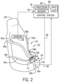
- FIG. 2 illustrates an embodiment of the restraint system 30 in which the 5-point harness 32 is in a locked configuration.
- FIGS. 3 and 4 illustrates embodiments of the restraint system 30 in which the 5-point harness 32 is in the unlocked configuration.
- the 5-point harness 32 includes multiple straps 56 (56a, 56b, 56c, 56d, 56e) that are coupled to the rider seat 28 at five different locations.
- the straps 56 are each coupled to a respective point 58 (58a, 58b, 58c, 58d, 58e) of the rider seat 28 that correspond to positions where the rider's shoulders, hips, and area between the legs are located when the rider 16 is properly seated in the rider seat 28.
- the straps 56a, 56b are positioned at the point 58a, 58b corresponding to the location where the rider's shoulders would rest when seated in the rider seat 28.
- the straps 56c, 56d are positioned at the points 58c, 58d, respectively, corresponding to the location where the rider's hips would rest when seated in the rider seat 28.
- the strap 56e is positioned at the point 58e corresponding to a location between the rider's legs when the rider 16 is seated within the ride seat 28.
- the 5-point harness 32 may be adjustable to allow proper restraining for riders of various sizes and shapes. Certain restraining systems such as waist belts (e.g., seat belt), restraint bars (e.g., lap bars and overhead bars), and the like, may only secure a portion of the rider (e.g., only at the waist, legs, shoulders). Therefore, it may be difficult to properly secure riders of various sizes and shapes.
- the 5 point harness 32 restrains the rider 16 in a manner such that various portions of the straps 56 are in contact with various portions of the rider's upper body (e.g., shoulders, waist, and chest). In this way, the rider's upper body is completely secured within the rider seat 28. By securing the rider's upper body, the 5-point harness 32 may facilitate restraining riders of various shapes and sizes.
- the straps 56 include features that facilitate coupling of one or more straps 56 to the lock 38.
- the one or more straps 56 include a female connector 60 (60a, 60b, 60c) that is removably coupled to a male connector 62 (62a, 62b, 62c) positioned on the lock 38.
- the straps 56a, 56c and 56b, 56d are arranged such that a loop 68 (e.g., opening) is formed between the respective straps 56a, 56c and 56b, 56d.
- the rider 16 When the rider 16 is seated in the ride seat 28, the rider 16 may slip their arms into and through the loops 68 before coupling the female connector 60 to the respective male connector 62 on the lock 38.
- the straps 56a, 56b are adjoined and arranged such that a loop 70 (e.g., opening) is formed between the straps 56a, 56b.
- the rider When the rider 16 is seated in the ride seat 28, the rider may slip their head into and through the loop 70 to position the straps 56a, 56b against their shoulders.
- the rider 16 may insert the female connector 60 into the respective male connector 62 to removably couple the straps 56 to the lock 38.
- the locking mechanism 36 may be activated to secure the rider 16 within the ride vehicle 20.
- the locking mechanism 36 includes a radio frequency identification (RFID) feature 72 that may function as an electronic key to lock and unlock the locking mechanism 36.
- RFID radio frequency identification
- the RFID feature 72 may be a receiver that receives an activation signal 80 from a control system 82 prior to the start of the amusement park ride 10 (e.g., before movement of the ride vehicle 20 along the tracks 24).
- the control system 82 may be part of a main control system of the amusement park ride 10 or a separate control system integrated into, for example, the gate 46.
- the control system 82 may detect that a rider 16 is occupying the ride seat 28 and, in response, transmit the activation signal 80 to the RFID feature 72. For example, once the control system 82 identifies that the rider 16 is occupying the ride seat 28, the control system 82 may transmit the activation signal 82 once the ride vehicle approaches the lock point at the loading station 38.
- the crew member 34 may actuate the locking mechanism using the hand held device 52.
- the control system 82 may include a processor 81, which may include one or more processing devices, and a memory 83 storing instructions executable by the processor 81.
- the memory 83 may include one or more tangible, non-transitory, machine-readable media.
- machine-readable media can include RAM, ROM, EPROM, EEPROM, optical disk storage, magnetic disk storage or other magnetic storage devices, or any other medium which can be used to carry or store desired program code in the form of machine-executable instructions or data structures and which can be accessed by the processor 81 or by any general purpose or special purpose computer or other machine with a processor.
- the control system 82 may also include communications circuitry and/or input and output circuitry to facilitate communication with other components of the amusement park ride 10.
- control system 82 may be coupled, either directly or wirelessly, to an operator input device or operator interface that, in operation, may be used by a ride technician to provide input used to control one or more ride features.
- the operator interface, or other components of the ride 10 may be located remotely from the control system 82 in certain embodiments and may be, for example, implemented on a mobile device.
- the control system 82 may also have a radio frequency (RF) chip 86 that detects the RFID feature 72 and transmits the activation signal 80 to the locking mechanism 36.
- the RFID feature 72 may transmit a signal 90 that is detected by the RF chip 86.
- the control system 82 outputs the activation signal 80 to activate the locking mechanism 36.
- the locking mechanism 36 may actuate a locking pin or other suitable locking mechanism within the lock 38, which secures and blocks movement of the female connectors 60 out of the respective male connectors 62 in the lock 38. By blocking movement of the female connectors 60, the rider 16 may be unable to prematurely unlock the locking mechanism 36 while the ride vehicle 20 is in motion.
- the RFID feature 72 is shown as being part of the lock 38, in other embodiments the RFID feature 72 is part of the female connectors 60.
- the RF chip 86 in the control system 82 may, at the lock point, emit a blanket locking signal to all ride vehicles 20 in-range. In other embodiments, the RF chip 86 may emit the locking signal after a handshake communication (e.g., detection) of each rider 16 restrained within the ride vehicle 20.
- the ride seat 28 may include a sensor 94 that determines whether the restraint system 30 of each ride seat 28 is in the restrained or unrestrained configuration. For example, when the restraint system 30 is in the unrestrained configuration, the sensor 94 may transmit a signal to the control system (e.g., the control system 82) indicating that the restraint system 30 is in the unrestrained configuration. The control system may block release of the ride vehicle 20 from the lock point and or the control point until the restraint system 30 is in the restrained configuration. As such, the crew member 34 may need to verify that the ride seat 28 is vacant, manually couple the female connectors 60 to the male connectors 62, and activate the locking mechanism using the hand held device 52.
- the control system e.g., the control system 82
- the control system may then determine that all restraint systems 30 in the ride vehicle 20 are secured and release the ride vehicle 20.
- the sensor 94 is positioned on a back rest of the ride seat 28.
- the sensor 94 may be positioned at any other location on the ride seat 28 or the ride vehicle 20 that facilitates communication with the restraint system 30 and/or the control system 82.
- the sensor 94 may transmit a signal indicative of an unoccupied ride seat 28.
- the control system may determine that the ride seat 28 is unoccupied and allow release of the ride vehicle from the control point with the restraint system 30 corresponding to the unoccupied seat 28 being in the unrestrained configuration.
- the sensor 94 may receive a signal from retro-reflective markers positioned on the ride seat 28. The retro-reflective markers may reflect light that is detected by the sensor 94. Based on the intensity of the reflected light or the degree of attenuation of the reflected light detected by the sensor 94, the control system 82 may determine whether the ride seat 28 is occupied or unoccupied.
- the rider 16 when the rider 16 is positioned within the ride seat 28, the rider 16 may block at least a portion of the retro-reflective markers. As such, the light reflected by the retro-reflective markers may be attenuated. However, when the ride seat 28 is unoccupied, the retro-reflective markers are not blocked and the intensity of the light reflected by the retro-reflective markers would be greater than the intensity of light reflected with the ride seat is occupied. Accordingly, the control system 82 may determine that the ride seat is unoccupied.
- the sensor 94 may be a pressure sensor disposed on the ride seat 28.
- the sensor 94 may be disposed on a back rest or seat cushion of the ride seat 28.
- the pressure sensor may transmit a signal to the control system 82 indicative of a pressure exerted on the ride seat 28. If the pressure signal is less than a predetermined value (e.g., less than approximately 5 pounds per square inch), the control system 82 may determine that the ride seat is unoccupied. As such, the control system 82 may release the ride vehicle 20 from the control point with the restraint system 30 corresponding to the unoccupied ride seat 28 in the unrestrained configuration.
- a predetermined value e.g., less than approximately 5 pounds per square inch
- the restraint system 30 may be unlocked.
- the RFID feature 72 may receive a deactivation signal 96 emitted by the gate 46 and/or the control system 82 of the amusement park ride 10.
- the RFID chip 86 detects the RFID feature 72 (e.g., signal 90) when the ride vehicle 20 is at the unloading station 38.
- the gate 46 and/or the control system 82 transmits the deactivation signal 96 to the RFID feature 72.
- the locking mechanism 36 may unlock the lock 38 to allow the rider 16 to uncouple the female connector 60 from the male connector 62 and exit the ride vehicle 20.
- the crew member 34 may deactivate the locking mechanism 36 of the restraint system 30 using the hand held transmitter 52, a key card, or other electronic key By deactivating the locking mechanism 36 of the restraint system 30 via the wireless signal, premature unlocking of the lock 38 may be mitigated.
- a power source used to actuate power controlled restraint systems may not need to be integrated into the ride vehicle 20. Accordingly, existing amusement park rides that do not include a power source may be retrofit with the restraint system 30, thereby decreasing the cost associated with implementing a power source into the amusement park ride and improving the restraint system to better secure and retain a rider within the ride seat throughout the duration of the amusement park ride.
- the 5-point harness restraint system disclosed herein may also facilitate securing riders of various shapes and sized by restraining the rider at various points along the rider's body (e.g., shoulders, waist, and chest).
- the locking mechanism 36 may also be incorporated into other type of restraining systems that do not include the 5-point harness 32.
- the locking mechanism may be incorporated into a seat belt, a restraint bar (e.g., lap bar or an overhead bar) or any other suitable restraint system used to secure a rider within a ride seat of an amusement park ride.
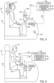
- FIG. 5 is a side-view of an embodiment of the restraint system 30 having a restraint bar 100 in the unrestrained configuration that is used to restrain and secure the rider 16 within the ride vehicle 20.
- FIG. 6 is a side-view of the restraint bar 100 in the restrained configuration.
- the restraint bar 100 includes a pivoting arm 104 that rotates about an axis 108 to move the restraint bar 100 between the restrained ( FIG. 6 ) and unrestrained ( FIG. 5 ) configurations.
- the restraint system 30 includes a locking mechanism that is activated and deactivated by a wireless signal.
- the restraint bar 100 includes the RFID feature 72 positioned within the pivoting arm 104. The RFID feature 72 transmits the signal 90 to the control system 82, signaling the control system 82 to transmit the activation signal 80.
- the pivoting arm 104 Upon receiving the activation signal 80 from the control system 82, the pivoting arm 104 rotates about the axis 108, as shown by arrow 112, to move the restraint bar 100 from the unrestrained configuration to the restrained configuration. For example, the pivoting arm 104 rotates toward the rider 16 in the direction 112 to position the restraint bar 100 in the restrained configuration.
- the ride vehicle 20 may include one or more sensors 116 communicatively coupled to the control system 82 of the amusement park ride 10.
- the one or more sensors 116 may transmit a signal 120 to the control system 82 indicating that the ride seat 28 is occupied and that the rider 16 may need to be secured within the ride seat 28.
- near-field communications may be utilized to determine that the rider 16 is seated in the ride seat 28.
- the control system 82 transmits the activation signal 80 causing the pivoting arm 104 to move toward the rider 16 in the direction 108.
- the pivoting arm 104 locks to block rotation of the pivoting arm 104 and securing the rider 16 within the ride seat 28.
- the crew member 34 may activate the pivoting arm 104 with the hand held transmitter 52.
- the control system 82 may activate a light 124 on the ride vehicle 20 to indicate that the rider 16 is secured and the ride vehicle 20 is released from the loading station 40.
- the pivoting arm 104 may be unlocked to enable rotation of the pivoting arm 104 in a direction 128 away from the rider 16, as shown in FIG. 6 .
- the RFID feature 72 receives the deactivation signal 94 from the control system 82 of the amusement park ride 10.
- the gate 46 or the crew member 34 e.g., via the hand held transmitter 52
- the pivoting arm 104 rotates in the direction 128 about the axis 108 to move the restraint bar 100 from the restrained configuration of the unrestrained configuration.
- the rider 16 may be unrestrained and exits the ride vehicle 20 at the unloading station 40.
Landscapes
- Engineering & Computer Science (AREA)
- Mechanical Engineering (AREA)
- Automation & Control Theory (AREA)
- Lock And Its Accessories (AREA)
- Seats For Vehicles (AREA)
- Automotive Seat Belt Assembly (AREA)
- Automatic Cycles, And Cycles In General (AREA)
Description
- The present disclosure relates generally to the field of amusement parks. More specifically, embodiments of the present disclosure relate to systems and methods for securing guests inside a ride vehicle of an amusement park ride.
- Various amusement park rides have been created to provide riders with unique motion and visual experiences. For example, theme rides can be implemented with single-rider or multi-rider vehicles that travel along a path or that utilize a motion base. Excitement is often created by the speed or change in direction of the vehicles as they move along a ride path or follow a motion routine. For example, the ride path may include a number of features such as, but not limited to, tunnels, turns, ups, downs, loops, and so forth. While the riders are inside the operating ride, they may be subject to forces while the ride is in operation. Accordingly, it may be desirable to restrain and secure riders within the ride vehicle for the duration of the amusement park ride.
- Document
US2009031541 A1 describes a passenger restraint system including a seatbelt buckle mechanism which includes a tongue having an aperture for receiving the belt and a pair of opposing recesses formed in an opposite edge of the tongue. A housing is provided for receiving a tongue and a latch is pivotably attached to the housing for locking the tongue to the housing. A retainer is provided for releasably locking the housing and latch and a solenoid is disposed in an operative relationship with the retainer for moving the retainer out of engagement with the latch in a remote manner. Apertures in the housing and latch enable mechanical access to the retainer for moving the retainer out of engagement with the latch independent of this solenoid if desired or necessary. - Certain embodiments commensurate in scope with the present disclosure are summarized below. These embodiments are not intended to limit the scope of the disclosure, but rather these embodiments are intended only to provide a brief summary of certain disclosed embodiments. Indeed, the present disclosure may encompass a variety of forms that may be similar to or different from the embodiments set forth below.
- The present invention is directed to a system and a method of securing a rider inside a ride vehicle of an amusement park ride according to claims 1 and 15, respectively. Subsidiary aspects of the invention are provided in the dependent claims.
- These and other features, aspects, and advantages of the present disclosure will become better understood when the following detailed description is read with reference to the accompanying drawings in which like characters represent like parts throughout the drawings, wherein:
-
FIG. 1 is a schematic representation of an amusement park ride, whereby the amusement park ride includes a ride vehicle having a passive restraint system, in accordance with an embodiment of the present disclosure; -
FIG. 2 is a schematic representation of the passive restraint system ofFIG. 1 , whereby the passive restraint system includes a five-point harness restraint in a locked configuration and having a wireless locking and unlocking mechanism, in accordance with an embodiment of the present disclosure; -
FIG. 3 is a schematic representation of the passive restraint system ofFIG. 2 , whereby the five-point harness restraint includes separate shoulder straps and is in an unlocked configuration, in accordance with an embodiment of the present disclosure; -
FIG. 4 is a schematic representation of the passive restraint system ofFIG. 2 , whereby the five point harness restraint includes adjoined shoulder straps and is in an unlocked configuration, in accordance with an embodiment of the present disclosure; -
FIG. 5 is a schematic representation of a passive restraint system that may be used with the amusement park ride ofFIG. 1 , whereby the passive restraint system includes a restraint bar having a pivotable arm in an unlocked configuration and having a wireless locking and unlocking mechanism, in accordance with an embodiment of the present disclosure; and -
FIG. 6 is a schematic representation of the passive restraint system ofFIG. 5 , whereby the restraint bar is in a locked configuration, in accordance with an embodiment of the present disclosure. - One or more specific embodiments of the present disclosure will be described below. In an effort to provide a concise description of these embodiments, all features of an actual implementation may not be described in the specification. It should be appreciated that in the development of any such actual implementation, as in any engineering or design project, numerous implementation-specific decisions must be made to achieve the developers' specific goals, such as compliance with system-related and business-related constraints, which may vary from one implementation to another. Moreover, it should be appreciated that such a development effort might be complex and time consuming, but would nevertheless be a routine undertaking of design, fabrication, and manufacture for those of ordinary skill having the benefit of this disclosure.
- Present embodiments of the disclosure are directed to systems and methods for securing a rider inside a ride vehicle of an amusement park ride using passive restraint systems that do not use power to actuate a locking mechanism. For example, the disclosed systems and methods include a passive restraint system (e.g., seat belt, harness, restraint bar (e.g., lap bar, shoulder bar), and the like) that includes a locking mechanism that is activated and deactivated wirelessly (e.g., via electromagnetic signals). The locking mechanism may be activated at any time after loading and prior to the start of the amusement park ride to secure the rider within the ride vehicle throughout the duration of the amusement park ride. The disclosed locking mechanism may be inaccessible to the rider such that the rider may be unable to prematurely unlock the locking mechanism during operation of the ride. Once the amusement park ride ends, the locking mechanism may be deactivated, for example at an unlocking point at an unloading station, to release the rider from the ride vehicle.
- The disclosed techniques do not use active power to maintain the locked configuration and, therefore, are capable of locking and unlocking without active power to the ride vehicle. That is, the passive restraint systems will not unlock when the power being supplied is cut off. This is in contrast to active restraint systems that stay locked while receiving power but that unlock when the power is cut off. Certain existing ride restraints for securing riders within the ride vehicle use a power source implemented into the ride vehicle to lock and unlock the restraint. Power-operated or active ride restraint systems may ensure that the rider is restrained throughout the duration of the amusement park ride and while the restraint mechanism is receiving power from an active power source. The power is then cut off to the restraint after completion of the amusement park ride to allow the rider to exit the ride vehicle. However, power operated active restraint systems may be difficult to integrate into certain amusement park rides. For example, certain existing amusement park ride systems may not include a power source that may be used to actuate the power operated restraint system. Additionally, it may be difficult and/or costly to integrate a power source for the ride restraints into existing and/or new amusement park rides due, in part, to ride design and configurations. Therefore, by using wireless activation to control the locking mechanism, the disclosed restraint system may be retrofitted into existing ride vehicles that are not equipped with power sources.
-
FIG. 1 illustrates an embodiment of anamusement park ride 10 that uses a passive restraint system having a wireless locking mechanism to secure arider 16 during operation of theamusement park ride 10. In the illustrated embodiment, theamusement park ride 10 includes aride vehicle 20 that travels along atrack 24 defining a ride path of theamusement park ride 10. Theride vehicle 20 includes aride seat 28 that supports therider 16 within theride vehicle 20 and arestraint system 30 that secures therider 16 within theride seat 28 during operation of theamusement park ride 10. In the illustrated embodiment, therestraint system 30 includes a 5-point harness 32. However, in other embodiments, therestraint system 30 includes a seat belt (e.g., lap belt), a restraint bar (see, e.g.,FIGS. 5 and 6 ), or any other suitable restraining mechanism. - As discussed in further detail below, the
restraint system 30 includes alocking mechanism 36 having a lock 38 (e.g., a buckle, a clip, a lock, a fastener, and the like) that may be actuated wirelessly (e.g., via radio frequency or any other suitable electromagnetic signal). For example, thelocking mechanism 36 may be actuated at a loading/unloading station 40 to lock or unlock thelocking mechanism 36 and secure or release, respectively, therider 16 within theride seat 28. The loading station may include a lock point where the locking mechanism is actuated (e.g., automatically or by the crew member 34) to secure therider 16 in theride vehicle 20. In certain embodiments, the loading station may also include a control point where thecrew member 34 may verify that therider 16 is properly restrained within theride seat 28. Similarly, the unloading station may include an unlock point where the locking mechanism is deactivated to unlock and release the rider from theride vehicle 20. - As used herein, the "loading station" is intended to denote an area where the
rider 16 boards a ride vehicle of the amusement park ride. The "unloading station" as used herein is intended to denote an area where therider 16 exits a ride vehicle. In certain embodiments, the loading and unloading stations are located in different areas of theamusement park ride 10. In other embodiments, the loading and unloading stations are located in the same area of theamusement park ride 10. The "control point" as used herein is intended to denote a location where verification that therider 16 is properly secured within theride vehicle 20 takes place. The "lock point" as used herein is intended to denote the point at which the locking mechanism of therestraint system 30 is locked and unable to be unlocked. A "lock point" may refer to a location (e.g., the locking mechanism is locked beyond a certain physical location), a time point (e.g., the locking mechanism is locked after a particular time), or an event point (e.g., the locking mechanism is locked before a particular event, such as a vehicle movement start). The "unlock point" as used herein is intended to denote the point at which the locking mechanism of therestraint system 30 is unlocked. - As discussed previously, the
locking mechanism 36 of therestraint system 30 may be activated at the locking point prior to passing through the control point. In certain embodiments, the locking point may include a gate 46 (e.g., an RFID gate) positioned at theloading station 40. Thegate 46 includes atransmitter 48 that transmits awireless signal 50 to therestraint system 30. Thewireless signal 50 is configured to lock or unlock thelocking mechanism 36, as discussed in further detail below. In the illustrated embodiment, thegate 46 is positioned over thetracks 24. However, thegate 46 may be positioned at any other suitable location within theamusement park ride 10 that allows wireless communication between therestraint system 30 and thetransmitter 48. In other embodiments, thecrew member 34 may use a hand heldtransmitter 52 to transmit thewireless signal 50 to thelocking mechanism 36, thereby locking thelocking mechanism 36 and securing therider 16 within theride vehicle 20. - As discussed in detail below, the
locking mechanism 36 may not be unlocked without receiving a lock deactivation signal transmitted after completion of theamusement park ride 10. For example, thegate 46 or the hand heldtransmitter 52 transmits thewireless signal 50 at the unloadingstation 38 after completion of the ride to deactivate the locking mechanism and release therider 16 from theride vehicle 20. In certain embodiments, the hand heldtransmitter 52 may be used to override the activation signal from thegate 46, for example, when a rider needs to unload from theride vehicle 20 after passing through the lock point and before start of theamusement park ride 10. - As discussed previously, the
gate 40 is communicatively coupled to thelocking mechanism 36 and transmits the signal 50 (e.g., an activation or deactivation signal) that locks or unlocks therestraint system 30.FIG. 2 illustrates an embodiment of therestraint system 30 in which the 5-point harness 32 is in a locked configuration.FIGS. 3 and 4 illustrates embodiments of therestraint system 30 in which the 5-point harness 32 is in the unlocked configuration. The 5-point harness 32 includes multiple straps 56 (56a, 56b, 56c, 56d, 56e) that are coupled to therider seat 28 at five different locations. For example, the straps 56 are each coupled to a respective point 58 (58a, 58b, 58c, 58d, 58e) of therider seat 28 that correspond to positions where the rider's shoulders, hips, and area between the legs are located when therider 16 is properly seated in therider seat 28. For example, thestraps point rider seat 28. Thestraps points rider seat 28. Thestrap 56e is positioned at thepoint 58e corresponding to a location between the rider's legs when therider 16 is seated within theride seat 28. The 5-point harness 32 may be adjustable to allow proper restraining for riders of various sizes and shapes. Certain restraining systems such as waist belts (e.g., seat belt), restraint bars (e.g., lap bars and overhead bars), and the like, may only secure a portion of the rider (e.g., only at the waist, legs, shoulders). Therefore, it may be difficult to properly secure riders of various sizes and shapes. However, the 5point harness 32 restrains therider 16 in a manner such that various portions of the straps 56 are in contact with various portions of the rider's upper body (e.g., shoulders, waist, and chest). In this way, the rider's upper body is completely secured within therider seat 28. By securing the rider's upper body, the 5-point harness 32 may facilitate restraining riders of various shapes and sizes. - The straps 56 include features that facilitate coupling of one or more straps 56 to the
lock 38. For example, as illustrated in the embodiments ofFIGS. 3 and 4 , the one or more straps 56 include a female connector 60 (60a, 60b, 60c) that is removably coupled to a male connector 62 (62a, 62b, 62c) positioned on thelock 38. In the embodiment illustrated inFIG. 3 , thestraps respective straps rider 16 is seated in theride seat 28, therider 16 may slip their arms into and through theloops 68 before coupling the female connector 60 to the respective male connector 62 on thelock 38. In the embodiment illustrated inFIG. 4 , thestraps straps rider 16 is seated in theride seat 28, the rider may slip their head into and through theloop 70 to position thestraps - Once the straps 56 are properly positioned on the
rider 16, therider 16 may insert the female connector 60 into the respective male connector 62 to removably couple the straps 56 to thelock 38. Following coupling of the straps 56 to the lock 38 (e.g., via the connectors 60, 62), thelocking mechanism 36 may be activated to secure therider 16 within theride vehicle 20. In certain embodiments, thelocking mechanism 36 includes a radio frequency identification (RFID) feature 72 that may function as an electronic key to lock and unlock thelocking mechanism 36. For example, as illustrated inFIG. 2 , theRFID feature 72 may be a receiver that receives anactivation signal 80 from acontrol system 82 prior to the start of the amusement park ride 10 (e.g., before movement of theride vehicle 20 along the tracks 24). Thecontrol system 82 may be part of a main control system of theamusement park ride 10 or a separate control system integrated into, for example, thegate 46. Thecontrol system 82 may detect that arider 16 is occupying theride seat 28 and, in response, transmit theactivation signal 80 to theRFID feature 72. For example, once thecontrol system 82 identifies that therider 16 is occupying theride seat 28, thecontrol system 82 may transmit theactivation signal 82 once the ride vehicle approaches the lock point at theloading station 38. In certain embodiments, thecrew member 34 may actuate the locking mechanism using the hand helddevice 52. - The
control system 82 may include aprocessor 81, which may include one or more processing devices, and amemory 83 storing instructions executable by theprocessor 81. Thememory 83 may include one or more tangible, non-transitory, machine-readable media. By way of example, such machine-readable media can include RAM, ROM, EPROM, EEPROM, optical disk storage, magnetic disk storage or other magnetic storage devices, or any other medium which can be used to carry or store desired program code in the form of machine-executable instructions or data structures and which can be accessed by theprocessor 81 or by any general purpose or special purpose computer or other machine with a processor. Thecontrol system 82 may also include communications circuitry and/or input and output circuitry to facilitate communication with other components of theamusement park ride 10. In addition, thecontrol system 82 may be coupled, either directly or wirelessly, to an operator input device or operator interface that, in operation, may be used by a ride technician to provide input used to control one or more ride features. The operator interface, or other components of theride 10, may be located remotely from thecontrol system 82 in certain embodiments and may be, for example, implemented on a mobile device. - The
control system 82 may also have a radio frequency (RF)chip 86 that detects theRFID feature 72 and transmits theactivation signal 80 to thelocking mechanism 36. For example, theRFID feature 72 may transmit asignal 90 that is detected by theRF chip 86. In response to thesignal 90, thecontrol system 82 outputs theactivation signal 80 to activate thelocking mechanism 36. Upon receiving theactivation signal 80, thelocking mechanism 36 may actuate a locking pin or other suitable locking mechanism within thelock 38, which secures and blocks movement of the female connectors 60 out of the respective male connectors 62 in thelock 38. By blocking movement of the female connectors 60, therider 16 may be unable to prematurely unlock thelocking mechanism 36 while theride vehicle 20 is in motion. While in the illustrated embodiment theRFID feature 72 is shown as being part of thelock 38, in other embodiments theRFID feature 72 is part of the female connectors 60. Further, theRF chip 86 in thecontrol system 82 may, at the lock point, emit a blanket locking signal to all ridevehicles 20 in-range. In other embodiments, theRF chip 86 may emit the locking signal after a handshake communication (e.g., detection) of eachrider 16 restrained within theride vehicle 20. - In certain embodiments, the
ride seat 28 may include asensor 94 that determines whether therestraint system 30 of eachride seat 28 is in the restrained or unrestrained configuration. For example, when therestraint system 30 is in the unrestrained configuration, thesensor 94 may transmit a signal to the control system (e.g., the control system 82) indicating that therestraint system 30 is in the unrestrained configuration. The control system may block release of theride vehicle 20 from the lock point and or the control point until therestraint system 30 is in the restrained configuration. As such, thecrew member 34 may need to verify that theride seat 28 is vacant, manually couple the female connectors 60 to the male connectors 62, and activate the locking mechanism using the hand helddevice 52. The control system may then determine that allrestraint systems 30 in theride vehicle 20 are secured and release theride vehicle 20. In the illustrated embodiment thesensor 94 is positioned on a back rest of theride seat 28. However, thesensor 94 may be positioned at any other location on theride seat 28 or theride vehicle 20 that facilitates communication with therestraint system 30 and/or thecontrol system 82. - In other embodiments, the
sensor 94 may transmit a signal indicative of anunoccupied ride seat 28. Upon detection of the signal from thesensor 94, the control system may determine that theride seat 28 is unoccupied and allow release of the ride vehicle from the control point with therestraint system 30 corresponding to theunoccupied seat 28 being in the unrestrained configuration. For example, in certain embodiments, thesensor 94 may receive a signal from retro-reflective markers positioned on theride seat 28. The retro-reflective markers may reflect light that is detected by thesensor 94. Based on the intensity of the reflected light or the degree of attenuation of the reflected light detected by thesensor 94, thecontrol system 82 may determine whether theride seat 28 is occupied or unoccupied. For example, when therider 16 is positioned within theride seat 28, therider 16 may block at least a portion of the retro-reflective markers. As such, the light reflected by the retro-reflective markers may be attenuated. However, when theride seat 28 is unoccupied, the retro-reflective markers are not blocked and the intensity of the light reflected by the retro-reflective markers would be greater than the intensity of light reflected with the ride seat is occupied. Accordingly, thecontrol system 82 may determine that the ride seat is unoccupied. - In other embodiments, the
sensor 94 may be a pressure sensor disposed on theride seat 28. For example, thesensor 94 may be disposed on a back rest or seat cushion of theride seat 28. The pressure sensor may transmit a signal to thecontrol system 82 indicative of a pressure exerted on theride seat 28. If the pressure signal is less than a predetermined value (e.g., less than approximately 5 pounds per square inch), thecontrol system 82 may determine that the ride seat is unoccupied. As such, thecontrol system 82 may release theride vehicle 20 from the control point with therestraint system 30 corresponding to theunoccupied ride seat 28 in the unrestrained configuration. - After completion of the
amusement park ride 10, therestraint system 30 may be unlocked. For example, once theride 10 is complete and theride vehicle 20 is at a complete stop in the unloadingstation 40, theRFID feature 72 may receive adeactivation signal 96 emitted by thegate 46 and/or thecontrol system 82 of theamusement park ride 10. For example, similar to activation, theRFID chip 86 detects the RFID feature 72 (e.g., signal 90) when theride vehicle 20 is at the unloadingstation 38. Once theride vehicle 20 reaches the unlock point, thegate 46 and/or thecontrol system 82 transmits thedeactivation signal 96 to theRFID feature 72. In response to thedeactivation signal 96, thelocking mechanism 36 may unlock thelock 38 to allow therider 16 to uncouple the female connector 60 from the male connector 62 and exit theride vehicle 20. - In certain embodiments, the
crew member 34 may deactivate thelocking mechanism 36 of therestraint system 30 using the hand heldtransmitter 52, a key card, or other electronic key By deactivating thelocking mechanism 36 of therestraint system 30 via the wireless signal, premature unlocking of thelock 38 may be mitigated. Additionally, a power source used to actuate power controlled restraint systems may not need to be integrated into theride vehicle 20. Accordingly, existing amusement park rides that do not include a power source may be retrofit with therestraint system 30, thereby decreasing the cost associated with implementing a power source into the amusement park ride and improving the restraint system to better secure and retain a rider within the ride seat throughout the duration of the amusement park ride. The 5-point harness restraint system disclosed herein may also facilitate securing riders of various shapes and sized by restraining the rider at various points along the rider's body (e.g., shoulders, waist, and chest). - The
locking mechanism 36 may also be incorporated into other type of restraining systems that do not include the 5-point harness 32. For example, the locking mechanism may be incorporated into a seat belt, a restraint bar (e.g., lap bar or an overhead bar) or any other suitable restraint system used to secure a rider within a ride seat of an amusement park ride.FIG. 5 is a side-view of an embodiment of therestraint system 30 having arestraint bar 100 in the unrestrained configuration that is used to restrain and secure therider 16 within theride vehicle 20.FIG. 6 is a side-view of therestraint bar 100 in the restrained configuration. - The
restraint bar 100 includes apivoting arm 104 that rotates about anaxis 108 to move therestraint bar 100 between the restrained (FIG. 6 ) and unrestrained (FIG. 5 ) configurations. As discussed above, therestraint system 30 includes a locking mechanism that is activated and deactivated by a wireless signal. Accordingly, in the illustrated embodiment, therestraint bar 100 includes theRFID feature 72 positioned within the pivotingarm 104. TheRFID feature 72 transmits thesignal 90 to thecontrol system 82, signaling thecontrol system 82 to transmit theactivation signal 80. Upon receiving theactivation signal 80 from thecontrol system 82, the pivotingarm 104 rotates about theaxis 108, as shown byarrow 112, to move therestraint bar 100 from the unrestrained configuration to the restrained configuration. For example, the pivotingarm 104 rotates toward therider 16 in thedirection 112 to position therestraint bar 100 in the restrained configuration. - In certain embodiments, the
ride vehicle 20 may include one ormore sensors 116 communicatively coupled to thecontrol system 82 of theamusement park ride 10. The one ormore sensors 116 may transmit asignal 120 to thecontrol system 82 indicating that theride seat 28 is occupied and that therider 16 may need to be secured within theride seat 28. For example, near-field communications may be utilized to determine that therider 16 is seated in theride seat 28. In response to such a determination, thecontrol system 82 transmits theactivation signal 80 causing the pivotingarm 104 to move toward therider 16 in thedirection 108. Once the pivotingarm 104 is in the restrained configuration, the pivotingarm 104 locks to block rotation of the pivotingarm 104 and securing therider 16 within theride seat 28. In certain embodiments, thecrew member 34 may activate thepivoting arm 104 with the hand heldtransmitter 52. Thecontrol system 82 may activate a light 124 on theride vehicle 20 to indicate that therider 16 is secured and theride vehicle 20 is released from theloading station 40. - Upon completion of the
amusement park ride 10, the pivotingarm 104 may be unlocked to enable rotation of the pivotingarm 104 in adirection 128 away from therider 16, as shown inFIG. 6 . For example, as discussed above, theRFID feature 72 receives thedeactivation signal 94 from thecontrol system 82 of theamusement park ride 10. In other embodiments, thegate 46 or the crew member 34 (e.g., via the hand held transmitter 52) may transmit thedeactivation signal 96. In response to thedeactivation signal 96, the pivotingarm 104 rotates in thedirection 128 about theaxis 108 to move therestraint bar 100 from the restrained configuration of the unrestrained configuration. As such, therider 16 may be unrestrained and exits theride vehicle 20 at the unloadingstation 40. - Traditional systems and methods for activating restraint systems on amusement park rides use a power source that is integrated into the ride vehicle. However, it is now recognized that by using electromagnetic signals to activate and deactivate a locking mechanism of restraint systems, a power source may not need to be integrated into the ride vehicle. As such, costs associated with integrating a power source into existing and/or new ride vehicles may be decreased compared to ride vehicles that include a power source for the restraint system. Additionally, by using electromagnetic signals to activate and deactivate restraint locking mechanisms, premature unlocking of the restraint system may be mitigated and restraint design may be improved to secure riders of various sizes and shapes.
- While only certain features of the invention have been illustrated and described herein, many modifications and changes will occur to those skilled in the art. The scope of the invention is defined by the appended claims.
Claims (15)
- A system, comprising:
a ride vehicle (20) of an amusement park ride (10);a restraint system (30) coupled to the ride vehicle (20) and comprising a lock (38) having a detector configured to receive a wireless signal, wherein receiving the wireless signal causes the lock (38) to lock to a restrained configuration or unlock to an unrestrained configuration, and wherein the restraint system (30) is configured to secure a rider (16) within the ride vehicle (20);a sensor that determines whether the restraint system (30) of each ride seat (28) is in the restrained or unrestrained configuration;one or more sensors configured to detect whether a seat of the ride vehicle is occupied;wherein the system is configured to block release of the ride vehicle (20) until the restraint system (30) is in the restrained configuration unless it is determined that the seat is not occupied. - The system of claim 1, comprising:a lock control point comprising a first transmitter configured to transmit the wireless signal to cause the lock of the restraint system (30) to lock, wherein the lock control point is located at a load zone for the ride vehicle (20); andan unlock point comprising a second transmitter configured to transmit a second wireless signal to unlock the restraint system (30).
- The system of claim 2, wherein the first transmitter and the second transmitter are radio frequency (RF) chips configured to transmit the wireless signal, and wherein the detector is a radio frequency identification (RFID) tag.
- The system of claim 1, wherein the restraint system (30) comprises a five-point harness (32) having a plurality of straps (56) each having at least one end fixedly attached to a ride seat of the ride vehicle (20), wherein at least one strap of the plurality of straps (56) comprises a connector and at least one other strap of the plurality of straps (56) comprises the lock on a free end, wherein the connector is configured to be removably coupled to the lock to secure the rider (16) within the ride vehicle (20) when the lock is in a locked configuration.
- The system of claim 1, wherein the restraint system comprises a first strap comprising a first connector; a second strap comprising a second connector; a third strap comprising a lock configured to removably couple to the first connector and the second connector; and wherein the first connector and the second connector are at least partially retained within the lock in the locked configuration and are removable from the lock in the unlocked configuration.
- The system of claim 1, comprising a transmitter configured to transmit the wireless signal to cause the lock of the restraint system to transition between the locked configuration and the unlocked configuration, wherein the transmitter is a radio frequency (RF) chip configured to transmit the wireless signal, and wherein the detector is a radio frequency identification (RFID) tag.
- The system of claim 4, wherein the first strap and the second strap each comprise a first end and a second end attached to a ride seat of the ride vehicle such that a loop is formed between the first and second ends of each respective strap, and wherein the loop is configured to receive an arm of the rider.
- The system of claim 1, where the ride vehicle is configured to receive power from an external or internal power source to power operations of the ride vehicle and wherein the lock is configured to maintain the locked configuration when not receiving power from the power source.
- The system of claim 1, wherein the detector is positioned within the lock and comprises an RFID tag.
- The system of claim 1, wherein the restraint system (30) comprises a pivoting arm configured to rotate about an axis to move the pivoting arm between a restrained configuration and an unrestrained configuration, wherein the detector is disposed on the pivoting arm and comprises an RFID tag.
- The system of claim 1, wherein the restraint system comprises:
a restraining bar comprising a pivoting arm configured to move from a restrained configuration to an unrestrained configuration; and wherein receiving the wireless signal causes the pivoting arm to lock or unlock, wherein the pivoting arm is capable of pivoting when unlocked to transition from the restrained configuration to the unrestrained configuration and wherein the pivoting arm is fixed in the restrained configuration when locked. - The system of claim 1, comprising a portable transmitter configured to transmit the wireless signal.
- The system of claim 1, comprising one or more sensors configured to detect the rider (16) within a seat (28) of the ride vehicle (20).
- The system of claim 13, comprising a control system configured to transmit the wireless signal to the detector in response to receiving a signal from the one or more sensors indicative of the rider (16) occupying the seat (28) of the ride vehicle (20).
- A method of securing a rider inside a ride vehicle (20) of an amusement park ride (10) using a restraint system (30) configured to secure the rider (16) within the ride vehicle (20), the restraint system being coupled to the ride vehicle (20) and comprising a lock (38) having a detector configured to receive a wireless signal, the method comprising:receiving the wireless signal causes the lock (38) to lock to a restrained configuration or unlock to an unrestrained configuration,determining using a sensor whether the restraint system (30) of each ride seat (28) is in the restrained or unrestrained configuration;detecting using one or more sensors whether a seat of the ride vehicle is occupied;blocking release of the ride vehicle (20) until the restraint system (30) is in the restrained configuration unless it is determined that the seat is not occupied.
Applications Claiming Priority (3)
| Application Number | Priority Date | Filing Date | Title |
|---|---|---|---|
| US201762607770P | 2017-12-19 | 2017-12-19 | |
| US16/221,134 US12134366B2 (en) | 2017-12-19 | 2018-12-14 | Passive restraint techniques for amusement park rides |
| PCT/US2018/066079 WO2019126074A1 (en) | 2017-12-19 | 2018-12-17 | Passive restraint techniques for amusement park rides |
Publications (2)
| Publication Number | Publication Date |
|---|---|
| EP3727625A1 EP3727625A1 (en) | 2020-10-28 |
| EP3727625B1 true EP3727625B1 (en) | 2023-07-26 |
Family
ID=66814207
Family Applications (1)
| Application Number | Title | Priority Date | Filing Date |
|---|---|---|---|
| EP18830669.0A Active EP3727625B1 (en) | 2017-12-19 | 2018-12-17 | Passive restraint techniques for amusement park rides |
Country Status (11)
| Country | Link |
|---|---|
| US (2) | US12134366B2 (en) |
| EP (1) | EP3727625B1 (en) |
| JP (3) | JP7277464B2 (en) |
| KR (1) | KR102704076B1 (en) |
| CN (2) | CN111432902A (en) |
| CA (1) | CA3084669A1 (en) |
| ES (1) | ES2959515T3 (en) |
| MY (1) | MY207942A (en) |
| RU (1) | RU2020123609A (en) |
| SG (1) | SG11202004881TA (en) |
| WO (1) | WO2019126074A1 (en) |
Families Citing this family (13)
| Publication number | Priority date | Publication date | Assignee | Title |
|---|---|---|---|---|
| US11007960B1 (en) | 2017-04-13 | 2021-05-18 | Advanced Concepts in Manufacturing LLC | Restraint systems and restraint system methods |
| US12466352B2 (en) | 2017-04-13 | 2025-11-11 | Advanced Concepts in Manufacturing LLC | Restraint systems and restraint system methods |
| DE102017120645A1 (en) * | 2017-09-07 | 2019-03-07 | Mack Rides Gmbh & Co. Kg | Passenger seat and vehicle with at least one such passenger seat for a ride, method for operating a vehicle and ride with at least one such vehicle |
| US12134366B2 (en) * | 2017-12-19 | 2024-11-05 | Universal City Studios Llc | Passive restraint techniques for amusement park rides |
| AU2020222178B2 (en) * | 2019-02-11 | 2022-12-15 | Mack Rides Gmbh & Co. Kg | Amusement ride and method for operating an amusement ride |
| DE102019103301A1 (en) * | 2019-02-11 | 2020-08-13 | Mack Rides Gmbh & Co Kg | Amusement ride, and methods of operating an amusement ride |
| US12065099B2 (en) * | 2020-10-05 | 2024-08-20 | Universal City Studios Llc | Remote release, redundant restraint latch |
| EP4380708B1 (en) * | 2021-08-02 | 2025-09-17 | Universal City Studios LLC | Riding harness system and method |
| DE102021210921A1 (en) | 2021-09-29 | 2023-03-30 | Hawe Hydraulik Se | Locking unit for a passenger restraint device, amusement ride passenger unit with a passenger restraint device and a locking unit, and method for functional testing of a locking unit |
| US11958426B2 (en) * | 2022-05-10 | 2024-04-16 | Universal City Studios Llc | Seat restraint system and method for ride vehicle |
| DE202024101544U1 (en) * | 2023-04-04 | 2024-06-27 | Rinat Babayof | Seat belt buckle |
| US20250001962A1 (en) * | 2023-06-30 | 2025-01-02 | Universal City Studios Llc | Dynamically adjustable compliant lap restraint device |
| US11952020B1 (en) * | 2023-06-30 | 2024-04-09 | Universal City Studios Llc | System and method for controlling ride vehicle restraint via computer implemented process |
Family Cites Families (37)
| Publication number | Priority date | Publication date | Assignee | Title |
|---|---|---|---|---|
| US5015933A (en) * | 1989-11-15 | 1991-05-14 | Ridewerks, Ltd. | Seat base motion controller |
| US5489212A (en) | 1990-07-02 | 1996-02-06 | Sega Enterprises Ltd. | Rotating simulator and body holding apparatus therefor |
| US5182836A (en) | 1991-08-30 | 1993-02-02 | The Walt Disney Company | Pressure activated seat belt locking mechanism |
| US5403238A (en) | 1993-08-19 | 1995-04-04 | The Walt Disney Company | Amusement park attraction |
| US5529382A (en) * | 1994-04-15 | 1996-06-25 | The Walt Disney Company | Passenger restraint system |
| JP2000296734A (en) | 1999-02-08 | 2000-10-24 | Aprica Kassai Inc | Youth safety seat for automobile, protector, child care utensil protector, child care utensil and newborn baby bed |
| JP4131604B2 (en) * | 2000-06-28 | 2008-08-13 | 三菱重工業株式会社 | Amusement facilities and traveling bodies of amusement facilities |
| US6888475B2 (en) | 2002-01-10 | 2005-05-03 | Joshua Scott Darr | Control system for aircraft seat belt arrangement |
| JP2005520733A (en) | 2002-03-25 | 2005-07-14 | ヘンネ クルト | Aircraft training and entertainment device for traveling on stationary tracks |
| WO2004109583A1 (en) * | 2003-06-06 | 2004-12-16 | Stemco Llc | Wireless communication device, system for communication and communication method |
| JP2006101976A (en) * | 2004-10-01 | 2006-04-20 | Aprica Kassai Inc | Seat |
| JP4302038B2 (en) * | 2004-10-27 | 2009-07-22 | コンビ株式会社 | Seat belt coupling device |
| US7758435B2 (en) | 2005-09-02 | 2010-07-20 | Water Ride Concepts, Inc. | Amusement water rides involving interactive user environments |
| US7564360B2 (en) | 2006-03-03 | 2009-07-21 | Checkpoint Systems, Inc. | RF release mechanism for hard tag |
| US20080150345A1 (en) * | 2006-12-21 | 2008-06-26 | Blum Steven C | Guest Positioning Assembly |
| US7905789B2 (en) * | 2007-04-03 | 2011-03-15 | Team Ix, Ltd. | Specialized restraint systems for amusement rides |
| JP5258206B2 (en) | 2007-05-25 | 2013-08-07 | コンビ株式会社 | Seat belt holding structure |
| US20090031541A1 (en) | 2007-07-27 | 2009-02-05 | Pribonic Edward M | Passenger restraint system |
| US8453576B2 (en) | 2007-08-16 | 2013-06-04 | Vekoma Rides Engineering B.V. | Rollercoaster amusement device |
| US8090504B2 (en) * | 2008-01-09 | 2012-01-03 | International Business Machines Corporation | Feedback loop system for passenger safety |
| WO2010009482A2 (en) | 2008-07-18 | 2010-01-21 | Alieza Combrink | Restraining support |
| US9192865B2 (en) | 2008-07-30 | 2015-11-24 | Universal Studios LLC | System and method for controlling a vehicle on fixed path |
| US8123294B2 (en) * | 2008-09-10 | 2012-02-28 | Wonderland Nurserygoods Co., Ltd | Harness storage system for child car seats |
| RU84247U1 (en) | 2009-01-11 | 2009-07-10 | Роман Борисович Бабич | ATTRACTION |
| JP2012116387A (en) | 2010-12-02 | 2012-06-21 | Naka Trading Kk | Radio helicopter for water rescue, water accident sufferer rescue system and operation method thereof |
| US8490550B2 (en) * | 2011-07-26 | 2013-07-23 | Disney Enterprises, Inc. | Roller coaster with articulable seat backs |
| KR101329899B1 (en) | 2011-12-07 | 2013-11-14 | 서동진 | Remote controlling toy and Communication control method thereof |
| JP6030348B2 (en) * | 2012-06-15 | 2016-11-24 | 株式会社セガ・ライブクリエイション | Attraction device |
| US20130341993A1 (en) | 2012-06-25 | 2013-12-26 | Kacey K. Kennington | Buckle positioning device, and systems, kits, and methods relating thereto |
| JP6261274B2 (en) * | 2013-10-09 | 2018-01-17 | 株式会社ユー・エス・ジェイ | Safety support device for amusement vehicles |
| US9600999B2 (en) * | 2014-05-21 | 2017-03-21 | Universal City Studios Llc | Amusement park element tracking system |
| GB2544863B (en) * | 2014-06-30 | 2018-05-30 | Jaguar Land Rover Ltd | Seat belt management system and method |
| JP5991346B2 (en) | 2014-07-10 | 2016-09-14 | トヨタ自動車株式会社 | Vehicle seat |
| US9908625B2 (en) * | 2015-08-06 | 2018-03-06 | Ami Industries, Inc. | Occupant restraint system and method of operating |
| EP3445192B1 (en) * | 2016-04-21 | 2021-01-20 | IHC Design, LLC | Garment for harness system |
| US10460539B2 (en) * | 2016-08-24 | 2019-10-29 | Universal City Studios Llc | Loose item management systems and methods for amusement park rides |
| US12134366B2 (en) * | 2017-12-19 | 2024-11-05 | Universal City Studios Llc | Passive restraint techniques for amusement park rides |
-
2018
- 2018-12-14 US US16/221,134 patent/US12134366B2/en active Active
- 2018-12-17 CN CN201880079947.2A patent/CN111432902A/en active Pending
- 2018-12-17 ES ES18830669T patent/ES2959515T3/en active Active
- 2018-12-17 RU RU2020123609A patent/RU2020123609A/en unknown
- 2018-12-17 MY MYPI2020002675A patent/MY207942A/en unknown
- 2018-12-17 CA CA3084669A patent/CA3084669A1/en active Pending
- 2018-12-17 EP EP18830669.0A patent/EP3727625B1/en active Active
- 2018-12-17 CN CN202511709298.8A patent/CN121570819A/en active Pending
- 2018-12-17 SG SG11202004881TA patent/SG11202004881TA/en unknown
- 2018-12-17 KR KR1020207020943A patent/KR102704076B1/en active Active
- 2018-12-17 WO PCT/US2018/066079 patent/WO2019126074A1/en not_active Ceased
- 2018-12-17 JP JP2020533215A patent/JP7277464B2/en active Active
-
2023
- 2023-05-08 JP JP2023076585A patent/JP7601941B2/en active Active
-
2024
- 2024-11-04 US US18/936,072 patent/US20250058738A1/en active Pending
- 2024-12-05 JP JP2024212333A patent/JP2025065099A/en active Pending
Also Published As
| Publication number | Publication date |
|---|---|
| CN121570819A (en) | 2026-02-27 |
| JP7277464B2 (en) | 2023-05-19 |
| CA3084669A1 (en) | 2019-06-27 |
| CN111432902A (en) | 2020-07-17 |
| ES2959515T3 (en) | 2024-02-26 |
| RU2020123609A (en) | 2022-01-20 |
| KR20200100146A (en) | 2020-08-25 |
| RU2020123609A3 (en) | 2022-02-04 |
| US12134366B2 (en) | 2024-11-05 |
| JP2023109810A (en) | 2023-08-08 |
| SG11202004881TA (en) | 2020-06-29 |
| WO2019126074A1 (en) | 2019-06-27 |
| JP2025065099A (en) | 2025-04-17 |
| JP7601941B2 (en) | 2024-12-17 |
| US20190184935A1 (en) | 2019-06-20 |
| JP2021506433A (en) | 2021-02-22 |
| US20250058738A1 (en) | 2025-02-20 |
| MY207942A (en) | 2025-03-31 |
| KR102704076B1 (en) | 2024-09-05 |
| EP3727625A1 (en) | 2020-10-28 |
Similar Documents
| Publication | Publication Date | Title |
|---|---|---|
| EP3727625B1 (en) | Passive restraint techniques for amusement park rides | |
| EP4225617B1 (en) | Remote release, redundant restraint latch | |
| US20230173958A1 (en) | Locking harness | |
| US7489247B2 (en) | Wireless system provided in a vehicle to detect presence of child in a baby car seat | |
| JPH06207484A (en) | Remote controller for locking and locking release of passenger seat | |
| EP2307110A1 (en) | System and method for controlling a vehicle on fixed path | |
| US10717408B1 (en) | System and method for determining seatbelt routing | |
| HK40034669A (en) | Passive restraint techniques for amusement park rides | |
| US11952020B1 (en) | System and method for controlling ride vehicle restraint via computer implemented process | |
| HK40096004A (en) | Remote release, redundant restraint latch | |
| US20210331607A1 (en) | Child Seat Safety System | |
| JP2023143159A (en) | Child seat and vehicle system | |
| WO2020058319A1 (en) | An alarm system for safety belts and corresponding child safety seat | |
| KR20210073683A (en) | Seat belt module |
Legal Events
| Date | Code | Title | Description |
|---|---|---|---|
| STAA | Information on the status of an ep patent application or granted ep patent |
Free format text: STATUS: UNKNOWN |
|
| STAA | Information on the status of an ep patent application or granted ep patent |
Free format text: STATUS: THE INTERNATIONAL PUBLICATION HAS BEEN MADE |
|
| PUAI | Public reference made under article 153(3) epc to a published international application that has entered the european phase |
Free format text: ORIGINAL CODE: 0009012 |
|
| STAA | Information on the status of an ep patent application or granted ep patent |
Free format text: STATUS: REQUEST FOR EXAMINATION WAS MADE |
|
| 17P | Request for examination filed |
Effective date: 20200714 |
|
| AK | Designated contracting states |
Kind code of ref document: A1 Designated state(s): AL AT BE BG CH CY CZ DE DK EE ES FI FR GB GR HR HU IE IS IT LI LT LU LV MC MK MT NL NO PL PT RO RS SE SI SK SM TR |
|
| AX | Request for extension of the european patent |
Extension state: BA ME |
|
| DAV | Request for validation of the european patent (deleted) | ||
| DAX | Request for extension of the european patent (deleted) | ||
| STAA | Information on the status of an ep patent application or granted ep patent |
Free format text: STATUS: EXAMINATION IS IN PROGRESS |
|
| 17Q | First examination report despatched |
Effective date: 20210702 |
|
| RIC1 | Information provided on ipc code assigned before grant |
Ipc: B60R 22/48 19850101ALI20230104BHEP Ipc: B60R 21/02 19680901ALI20230104BHEP Ipc: B60R 21/00 19680901ALI20230104BHEP Ipc: A63G 7/00 19680901AFI20230104BHEP |
|
| GRAP | Despatch of communication of intention to grant a patent |
Free format text: ORIGINAL CODE: EPIDOSNIGR1 |
|
| STAA | Information on the status of an ep patent application or granted ep patent |
Free format text: STATUS: GRANT OF PATENT IS INTENDED |
|
| INTG | Intention to grant announced |
Effective date: 20230214 |
|
| GRAS | Grant fee paid |
Free format text: ORIGINAL CODE: EPIDOSNIGR3 |
|
| GRAA | (expected) grant |
Free format text: ORIGINAL CODE: 0009210 |
|
| STAA | Information on the status of an ep patent application or granted ep patent |
Free format text: STATUS: THE PATENT HAS BEEN GRANTED |
|
| P01 | Opt-out of the competence of the unified patent court (upc) registered |
Effective date: 20230522 |
|
| AK | Designated contracting states |
Kind code of ref document: B1 Designated state(s): AL AT BE BG CH CY CZ DE DK EE ES FI FR GB GR HR HU IE IS IT LI LT LU LV MC MK MT NL NO PL PT RO RS SE SI SK SM TR |
|
| REG | Reference to a national code |
Ref country code: CH Ref legal event code: EP |
|
| REG | Reference to a national code |
Ref country code: DE Ref legal event code: R096 Ref document number: 602018054200 Country of ref document: DE |
|
| REG | Reference to a national code |
Ref country code: IE Ref legal event code: FG4D |
|
| REG | Reference to a national code |
Ref country code: LT Ref legal event code: MG9D |
|
| REG | Reference to a national code |
Ref country code: NL Ref legal event code: MP Effective date: 20230726 |
|
| PG25 | Lapsed in a contracting state [announced via postgrant information from national office to epo] |
Ref country code: NL Free format text: LAPSE BECAUSE OF FAILURE TO SUBMIT A TRANSLATION OF THE DESCRIPTION OR TO PAY THE FEE WITHIN THE PRESCRIBED TIME-LIMIT Effective date: 20230726 |
|
| PG25 | Lapsed in a contracting state [announced via postgrant information from national office to epo] |
Ref country code: GR Free format text: LAPSE BECAUSE OF FAILURE TO SUBMIT A TRANSLATION OF THE DESCRIPTION OR TO PAY THE FEE WITHIN THE PRESCRIBED TIME-LIMIT Effective date: 20231027 |
|
| PG25 | Lapsed in a contracting state [announced via postgrant information from national office to epo] |
Ref country code: IS Free format text: LAPSE BECAUSE OF FAILURE TO SUBMIT A TRANSLATION OF THE DESCRIPTION OR TO PAY THE FEE WITHIN THE PRESCRIBED TIME-LIMIT Effective date: 20231126 |
|
| PG25 | Lapsed in a contracting state [announced via postgrant information from national office to epo] |
Ref country code: SE Free format text: LAPSE BECAUSE OF FAILURE TO SUBMIT A TRANSLATION OF THE DESCRIPTION OR TO PAY THE FEE WITHIN THE PRESCRIBED TIME-LIMIT Effective date: 20230726 Ref country code: RS Free format text: LAPSE BECAUSE OF FAILURE TO SUBMIT A TRANSLATION OF THE DESCRIPTION OR TO PAY THE FEE WITHIN THE PRESCRIBED TIME-LIMIT Effective date: 20230726 Ref country code: PT Free format text: LAPSE BECAUSE OF FAILURE TO SUBMIT A TRANSLATION OF THE DESCRIPTION OR TO PAY THE FEE WITHIN THE PRESCRIBED TIME-LIMIT Effective date: 20231127 Ref country code: NO Free format text: LAPSE BECAUSE OF FAILURE TO SUBMIT A TRANSLATION OF THE DESCRIPTION OR TO PAY THE FEE WITHIN THE PRESCRIBED TIME-LIMIT Effective date: 20231026 Ref country code: LV Free format text: LAPSE BECAUSE OF FAILURE TO SUBMIT A TRANSLATION OF THE DESCRIPTION OR TO PAY THE FEE WITHIN THE PRESCRIBED TIME-LIMIT Effective date: 20230726 Ref country code: LT Free format text: LAPSE BECAUSE OF FAILURE TO SUBMIT A TRANSLATION OF THE DESCRIPTION OR TO PAY THE FEE WITHIN THE PRESCRIBED TIME-LIMIT Effective date: 20230726 Ref country code: IS Free format text: LAPSE BECAUSE OF FAILURE TO SUBMIT A TRANSLATION OF THE DESCRIPTION OR TO PAY THE FEE WITHIN THE PRESCRIBED TIME-LIMIT Effective date: 20231126 Ref country code: HR Free format text: LAPSE BECAUSE OF FAILURE TO SUBMIT A TRANSLATION OF THE DESCRIPTION OR TO PAY THE FEE WITHIN THE PRESCRIBED TIME-LIMIT Effective date: 20230726 Ref country code: GR Free format text: LAPSE BECAUSE OF FAILURE TO SUBMIT A TRANSLATION OF THE DESCRIPTION OR TO PAY THE FEE WITHIN THE PRESCRIBED TIME-LIMIT Effective date: 20231027 Ref country code: FI Free format text: LAPSE BECAUSE OF FAILURE TO SUBMIT A TRANSLATION OF THE DESCRIPTION OR TO PAY THE FEE WITHIN THE PRESCRIBED TIME-LIMIT Effective date: 20230726 |
|
| REG | Reference to a national code |
Ref country code: AT Ref legal event code: UEP Ref document number: 1591270 Country of ref document: AT Kind code of ref document: T Effective date: 20230726 |
|
| REG | Reference to a national code |
Ref country code: ES Ref legal event code: FG2A Ref document number: 2959515 Country of ref document: ES Kind code of ref document: T3 Effective date: 20240226 |
|
| PG25 | Lapsed in a contracting state [announced via postgrant information from national office to epo] |
Ref country code: PL Free format text: LAPSE BECAUSE OF FAILURE TO SUBMIT A TRANSLATION OF THE DESCRIPTION OR TO PAY THE FEE WITHIN THE PRESCRIBED TIME-LIMIT Effective date: 20230726 |
|
| REG | Reference to a national code |
Ref country code: DE Ref legal event code: R097 Ref document number: 602018054200 Country of ref document: DE |
|
| PG25 | Lapsed in a contracting state [announced via postgrant information from national office to epo] |
Ref country code: SM Free format text: LAPSE BECAUSE OF FAILURE TO SUBMIT A TRANSLATION OF THE DESCRIPTION OR TO PAY THE FEE WITHIN THE PRESCRIBED TIME-LIMIT Effective date: 20230726 Ref country code: RO Free format text: LAPSE BECAUSE OF FAILURE TO SUBMIT A TRANSLATION OF THE DESCRIPTION OR TO PAY THE FEE WITHIN THE PRESCRIBED TIME-LIMIT Effective date: 20230726 Ref country code: EE Free format text: LAPSE BECAUSE OF FAILURE TO SUBMIT A TRANSLATION OF THE DESCRIPTION OR TO PAY THE FEE WITHIN THE PRESCRIBED TIME-LIMIT Effective date: 20230726 Ref country code: DK Free format text: LAPSE BECAUSE OF FAILURE TO SUBMIT A TRANSLATION OF THE DESCRIPTION OR TO PAY THE FEE WITHIN THE PRESCRIBED TIME-LIMIT Effective date: 20230726 Ref country code: CZ Free format text: LAPSE BECAUSE OF FAILURE TO SUBMIT A TRANSLATION OF THE DESCRIPTION OR TO PAY THE FEE WITHIN THE PRESCRIBED TIME-LIMIT Effective date: 20230726 Ref country code: SK Free format text: LAPSE BECAUSE OF FAILURE TO SUBMIT A TRANSLATION OF THE DESCRIPTION OR TO PAY THE FEE WITHIN THE PRESCRIBED TIME-LIMIT Effective date: 20230726 |
|
| PLBE | No opposition filed within time limit |
Free format text: ORIGINAL CODE: 0009261 |
|
| STAA | Information on the status of an ep patent application or granted ep patent |
Free format text: STATUS: NO OPPOSITION FILED WITHIN TIME LIMIT |
|
| 26N | No opposition filed |
Effective date: 20240429 |
|
| PG25 | Lapsed in a contracting state [announced via postgrant information from national office to epo] |
Ref country code: SI Free format text: LAPSE BECAUSE OF FAILURE TO SUBMIT A TRANSLATION OF THE DESCRIPTION OR TO PAY THE FEE WITHIN THE PRESCRIBED TIME-LIMIT Effective date: 20230726 |
|
| PG25 | Lapsed in a contracting state [announced via postgrant information from national office to epo] |
Ref country code: LU Free format text: LAPSE BECAUSE OF NON-PAYMENT OF DUE FEES Effective date: 20231217 |
|
| PG25 | Lapsed in a contracting state [announced via postgrant information from national office to epo] |
Ref country code: MC Free format text: LAPSE BECAUSE OF FAILURE TO SUBMIT A TRANSLATION OF THE DESCRIPTION OR TO PAY THE FEE WITHIN THE PRESCRIBED TIME-LIMIT Effective date: 20230726 |
|
| REG | Reference to a national code |
Ref country code: BE Ref legal event code: MM Effective date: 20231231 |
|
| PG25 | Lapsed in a contracting state [announced via postgrant information from national office to epo] |
Ref country code: MC Free format text: LAPSE BECAUSE OF FAILURE TO SUBMIT A TRANSLATION OF THE DESCRIPTION OR TO PAY THE FEE WITHIN THE PRESCRIBED TIME-LIMIT Effective date: 20230726 Ref country code: LU Free format text: LAPSE BECAUSE OF NON-PAYMENT OF DUE FEES Effective date: 20231217 |
|
| REG | Reference to a national code |
Ref country code: IE Ref legal event code: MM4A |
|
| PG25 | Lapsed in a contracting state [announced via postgrant information from national office to epo] |
Ref country code: IE Free format text: LAPSE BECAUSE OF NON-PAYMENT OF DUE FEES Effective date: 20231217 |
|
| PG25 | Lapsed in a contracting state [announced via postgrant information from national office to epo] |
Ref country code: BE Free format text: LAPSE BECAUSE OF NON-PAYMENT OF DUE FEES Effective date: 20231231 |
|
| PG25 | Lapsed in a contracting state [announced via postgrant information from national office to epo] |
Ref country code: IE Free format text: LAPSE BECAUSE OF NON-PAYMENT OF DUE FEES Effective date: 20231217 Ref country code: BE Free format text: LAPSE BECAUSE OF NON-PAYMENT OF DUE FEES Effective date: 20231231 |
|
| PG25 | Lapsed in a contracting state [announced via postgrant information from national office to epo] |
Ref country code: BG Free format text: LAPSE BECAUSE OF FAILURE TO SUBMIT A TRANSLATION OF THE DESCRIPTION OR TO PAY THE FEE WITHIN THE PRESCRIBED TIME-LIMIT Effective date: 20230726 |
|
| PG25 | Lapsed in a contracting state [announced via postgrant information from national office to epo] |
Ref country code: BG Free format text: LAPSE BECAUSE OF FAILURE TO SUBMIT A TRANSLATION OF THE DESCRIPTION OR TO PAY THE FEE WITHIN THE PRESCRIBED TIME-LIMIT Effective date: 20230726 |
|
| PG25 | Lapsed in a contracting state [announced via postgrant information from national office to epo] |
Ref country code: CY Free format text: LAPSE BECAUSE OF FAILURE TO SUBMIT A TRANSLATION OF THE DESCRIPTION OR TO PAY THE FEE WITHIN THE PRESCRIBED TIME-LIMIT; INVALID AB INITIO Effective date: 20181217 |
|
| PG25 | Lapsed in a contracting state [announced via postgrant information from national office to epo] |
Ref country code: HU Free format text: LAPSE BECAUSE OF FAILURE TO SUBMIT A TRANSLATION OF THE DESCRIPTION OR TO PAY THE FEE WITHIN THE PRESCRIBED TIME-LIMIT; INVALID AB INITIO Effective date: 20181217 |
|
| PG25 | Lapsed in a contracting state [announced via postgrant information from national office to epo] |
Ref country code: TR Free format text: LAPSE BECAUSE OF FAILURE TO SUBMIT A TRANSLATION OF THE DESCRIPTION OR TO PAY THE FEE WITHIN THE PRESCRIBED TIME-LIMIT Effective date: 20230726 |
|
| REG | Reference to a national code |
Ref country code: CH Ref legal event code: U11 Free format text: ST27 STATUS EVENT CODE: U-0-0-U10-U11 (AS PROVIDED BY THE NATIONAL OFFICE) Effective date: 20260101 |
|
| PGFP | Annual fee paid to national office [announced via postgrant information from national office to epo] |
Ref country code: GB Payment date: 20251229 Year of fee payment: 8 |
|
| PGFP | Annual fee paid to national office [announced via postgrant information from national office to epo] |
Ref country code: AT Payment date: 20251230 Year of fee payment: 8 |
|
| PGFP | Annual fee paid to national office [announced via postgrant information from national office to epo] |
Ref country code: IT Payment date: 20251219 Year of fee payment: 8 |
|
| PGFP | Annual fee paid to national office [announced via postgrant information from national office to epo] |
Ref country code: FR Payment date: 20251226 Year of fee payment: 8 |
|
| PGFP | Annual fee paid to national office [announced via postgrant information from national office to epo] |
Ref country code: ES Payment date: 20260102 Year of fee payment: 8 |
|
| PGFP | Annual fee paid to national office [announced via postgrant information from national office to epo] |
Ref country code: DE Payment date: 20251229 Year of fee payment: 8 |
|
| PGFP | Annual fee paid to national office [announced via postgrant information from national office to epo] |
Ref country code: CH Payment date: 20260101 Year of fee payment: 8 |