EP3727490B1 - A self adhering surgical fabric and method of manufacturing same - Google Patents
A self adhering surgical fabric and method of manufacturing same Download PDFInfo
- Publication number
- EP3727490B1 EP3727490B1 EP18826671.2A EP18826671A EP3727490B1 EP 3727490 B1 EP3727490 B1 EP 3727490B1 EP 18826671 A EP18826671 A EP 18826671A EP 3727490 B1 EP3727490 B1 EP 3727490B1
- Authority
- EP
- European Patent Office
- Prior art keywords
- layer
- layers
- yarns
- woven
- self
- Prior art date
- Legal status (The legal status is an assumption and is not a legal conclusion. Google has not performed a legal analysis and makes no representation as to the accuracy of the status listed.)
- Active
Links
Images


Classifications
-
- A—HUMAN NECESSITIES
- A61—MEDICAL OR VETERINARY SCIENCE; HYGIENE
- A61L—METHODS OR APPARATUS FOR STERILISING MATERIALS OR OBJECTS IN GENERAL; DISINFECTION, STERILISATION OR DEODORISATION OF AIR; CHEMICAL ASPECTS OF BANDAGES, DRESSINGS, ABSORBENT PADS OR SURGICAL ARTICLES; MATERIALS FOR BANDAGES, DRESSINGS, ABSORBENT PADS OR SURGICAL ARTICLES
- A61L31/00—Materials for other surgical articles, e.g. stents, stent-grafts, shunts, surgical drapes, guide wires, materials for adhesion prevention, occluding devices, surgical gloves, tissue fixation devices
- A61L31/04—Macromolecular materials
-
- A—HUMAN NECESSITIES
- A61—MEDICAL OR VETERINARY SCIENCE; HYGIENE
- A61L—METHODS OR APPARATUS FOR STERILISING MATERIALS OR OBJECTS IN GENERAL; DISINFECTION, STERILISATION OR DEODORISATION OF AIR; CHEMICAL ASPECTS OF BANDAGES, DRESSINGS, ABSORBENT PADS OR SURGICAL ARTICLES; MATERIALS FOR BANDAGES, DRESSINGS, ABSORBENT PADS OR SURGICAL ARTICLES
- A61L31/00—Materials for other surgical articles, e.g. stents, stent-grafts, shunts, surgical drapes, guide wires, materials for adhesion prevention, occluding devices, surgical gloves, tissue fixation devices
- A61L31/04—Macromolecular materials
- A61L31/048—Macromolecular materials obtained by reactions only involving carbon-to-carbon unsaturated bonds
-
- A—HUMAN NECESSITIES
- A61—MEDICAL OR VETERINARY SCIENCE; HYGIENE
- A61L—METHODS OR APPARATUS FOR STERILISING MATERIALS OR OBJECTS IN GENERAL; DISINFECTION, STERILISATION OR DEODORISATION OF AIR; CHEMICAL ASPECTS OF BANDAGES, DRESSINGS, ABSORBENT PADS OR SURGICAL ARTICLES; MATERIALS FOR BANDAGES, DRESSINGS, ABSORBENT PADS OR SURGICAL ARTICLES
- A61L31/00—Materials for other surgical articles, e.g. stents, stent-grafts, shunts, surgical drapes, guide wires, materials for adhesion prevention, occluding devices, surgical gloves, tissue fixation devices
- A61L31/04—Macromolecular materials
- A61L31/06—Macromolecular materials obtained otherwise than by reactions only involving carbon-to-carbon unsaturated bonds
-
- A—HUMAN NECESSITIES
- A61—MEDICAL OR VETERINARY SCIENCE; HYGIENE
- A61L—METHODS OR APPARATUS FOR STERILISING MATERIALS OR OBJECTS IN GENERAL; DISINFECTION, STERILISATION OR DEODORISATION OF AIR; CHEMICAL ASPECTS OF BANDAGES, DRESSINGS, ABSORBENT PADS OR SURGICAL ARTICLES; MATERIALS FOR BANDAGES, DRESSINGS, ABSORBENT PADS OR SURGICAL ARTICLES
- A61L31/00—Materials for other surgical articles, e.g. stents, stent-grafts, shunts, surgical drapes, guide wires, materials for adhesion prevention, occluding devices, surgical gloves, tissue fixation devices
- A61L31/14—Materials characterised by their function or physical properties, e.g. injectable or lubricating compositions, shape-memory materials, surface modified materials
-
- D—TEXTILES; PAPER
- D03—WEAVING
- D03D—WOVEN FABRICS; METHODS OF WEAVING; LOOMS
- D03D11/00—Double or multi-ply fabrics not otherwise provided for
-
- D—TEXTILES; PAPER
- D03—WEAVING
- D03D—WOVEN FABRICS; METHODS OF WEAVING; LOOMS
- D03D27/00—Woven pile fabrics
- D03D27/02—Woven pile fabrics wherein the pile is formed by warp or weft
- D03D27/06—Warp pile fabrics
- D03D27/08—Terry fabrics
-
- D—TEXTILES; PAPER
- D03—WEAVING
- D03D—WOVEN FABRICS; METHODS OF WEAVING; LOOMS
- D03D27/00—Woven pile fabrics
- D03D27/02—Woven pile fabrics wherein the pile is formed by warp or weft
- D03D27/10—Fabrics woven face-to-face, e.g. double velvet
Definitions
- This invention relates to a self adhering surgical fabric and a method of manufacturing same, which fabric may be used as a scaffold, support or closure member in various surgical procedures in order to reduce surgical time and complexity.
- Surgical fabrics or meshes are commonly used in various surgical procedures to provide a permanent or temporary support to organs or other tissue while a particular surgical procedure is performed, for example a hernia repair, pelvic organ prolapse, wound closure, surgical incision closure, vessel puncture site closure, AAA/TAA endovascular grafting to inhibit migration, and integration into oesophageal or biliary covered stents to inhibit migration.
- the meshes are conventionally manufactured from a polymer and may be inorganic or biological, and are often a bioabsorbable material such that the mesh can be left in situ and will be absorbed into the surrounding tissue over time in order to avoid the requirement for further surgery to remove the mesh.
- WO2010139340 discloses a medical device comprising yarns made of a shape memory material and polymer yarns, wherein the yarns made of said shape memory material have a polymer sheathing and having an outer surface including structures to allow anchoring or securing of the device in a surrounding tissue region.
- WO9310731 discloses a pad to be applied to bleeding tissue and having a textured surface which may include long or short spikes or barbs, or hook like members and/or loop like members.
- a method of manufacturing a self-adhering surgical fabric comprising the steps of:
- the method comprises weaving or knitting the first and second layers of material (12; 112, 14)
- the method comprises cutting the connecting yarns using a hot knife.
- the method comprises forming the respective first and second free ends as first and second heads (118) that are configured to function as the anchors or hooks to self-adhere the respective first and second layers of material to tissue
- the method comprises forming the first and second heads (118) simultaneously with cutting the connecting yarn.
- the method comprises orienting the connecting yarns (16: 116) perpendicularly to the first and second layers of material (12; 112, 14)
- the method comprises orienting the connecting yarns (16; 116) non-perpendicularly to the first and second layers of material (12; 112, 14).
- a self-adhering surgical fabric (10; 110) comprising a layer of a woven material or a knitted material(12; 112, 14) having an array of yarns (16; 116) projecting from a face of the layer of woven or knitted material (12; 112, 14) to an array of mushroom-shaped heads (118) that are configured to function as anchors or hooks to self-adhere the layer of woven or knitted material comprising the surgical fabric to tissue.
- the layer of woven or knitted material (12; 112, 14) is formed from monofilament, multifilament or ring spun yarns of regenerated silk, nylon/high tension nylon, PET/high tension PET, UHMWPE, or LCP (liquid crystal polymer).
- the first and second layers of material are constructed from resorbable polymers selected from the group of PLA, PLLA, PGA, PLGA, Polycaprolactone or Polydioxanone.
- each connecting yarn is oriented perpendicularly to the face of the layer of material.
- each connecting yarn is oriented non perpendicularly to the face of the layer of material.
- the yarns comprising the first and second layers of material are heat set before being woven or knitted into the first and second layers.
- a layered fabric generally indicated as (10), which comprises a first layer of material (12) and a second layer of material (14) in parallel spaced relationship to one another, and connected together by an array of connecting yarns (16) extending between the layers (12), (14).
- the connecting yarns (16) may extend perpendicularly from one or both of the layers (12), (14) or may extend at an angle to one or both of the layers (12), (14).
- the first layer (12) and/or the second layer (14) may be formed as a woven material or as a knitted material, or any other suitable construction.
- a woven material is produced by orienting yarns along both X and Y axes, that is by arranging a series of warp yarns adjacent one another and interspersing or interweaving weft yarns.
- the resulting material often tends to offer minimal compliance, depending on the yarn or combination of yarns utilised. It will be appreciated that the physical characteristics of the yarns and the weave may be varied to provided particular desired characteristics such as flexibility, porosity, etc.
- the first and/or second layers of material (12), (14) may be constructed from monofilament, multifilament or ring spun yarns of regenerated silk, nylon/high tension nylon, PET/high tension PET, UHMWPE, LCP (liquid crystal polymer) or any other suitable material. Where a multifilament is utilised this may be heat set in a twisted condition or not.
- the layers of material (12), (14) may also be constructed from resorbable polymers, for example PLA, PLLA, PGA, PLGA, Polycaprolactone or Polydioxanone.
- the yarns utilised in the construction of the layers of material (12), (14) can range from 5 to 500 denier.
- the method according to the present invention then involves separating the first layer of material (12) from the second layer of material (14) by cutting through the connecting yarns (16) such that a portion of each connecting yarn (16) remains attached to both the first layer (12) and to the second layer (14), either of which then define a self adhering surgical fabric (110) according to the invention and as illustrated in Figures 4 to 7 .
- a knife K which may be heated, is used to cut through the connecting yarns (16) to form the two portions of self adhering fabric (110).
- Potential surgical applications for the self adhering surgical fabric (110) include fixation to treat pelvic organ prolapse, wound closure, surgical incision closure, vessel puncture site closure, AAA/TAA endovascular grafts to inhibit migration, and integration into oesophageal or biliary covered stents to inhibit migration.
- each of the connecting yarns (116) may be shaped to define a head or barb (118) which will increase the grip generated when the yarns (116) engage with the target tissue.
- the heads (118) may be formed simultaneously with cutting of the connecting yarns (16) by the knife K, which may be heated in order to partially melt the free end of each connecting yarn (16) as it is cut, thereby deforming the free end of the connecting yarn (16) to form the head (118).
- the method of forming the self adhering surgical fabric (110) of the present invention may also include the step of engaging a hot platen P1, P2 or P3 against the free end of each of the yarns (116) in order to melt and deform the free end to form the head (118).
- the platen P1 comprises a flat contact surface to engage against the yarns (116), while the platens P2 and P3 incorporate a spiked and a domed contact surface in order to generate a barbed or mushroom shaped head (118) when pressed into engagement with the yarns (116). It will of course be appreciated that any other functional alternative may be employed in order to form the shaped heads (118).
Landscapes
- Health & Medical Sciences (AREA)
- Heart & Thoracic Surgery (AREA)
- Surgery (AREA)
- Vascular Medicine (AREA)
- Epidemiology (AREA)
- Life Sciences & Earth Sciences (AREA)
- Animal Behavior & Ethology (AREA)
- General Health & Medical Sciences (AREA)
- Public Health (AREA)
- Veterinary Medicine (AREA)
- Engineering & Computer Science (AREA)
- Textile Engineering (AREA)
- Chemical & Material Sciences (AREA)
- Chemical Kinetics & Catalysis (AREA)
- Knitting Of Fabric (AREA)
- Woven Fabrics (AREA)
- Materials For Medical Uses (AREA)
Description
- This invention relates to a self adhering surgical fabric and a method of manufacturing same, which fabric may be used as a scaffold, support or closure member in various surgical procedures in order to reduce surgical time and complexity.
- Surgical fabrics or meshes are commonly used in various surgical procedures to provide a permanent or temporary support to organs or other tissue while a particular surgical procedure is performed, for example a hernia repair, pelvic organ prolapse, wound closure, surgical incision closure, vessel puncture site closure, AAA/TAA endovascular grafting to inhibit migration, and integration into oesophageal or biliary covered stents to inhibit migration. The meshes are conventionally manufactured from a polymer and may be inorganic or biological, and are often a bioabsorbable material such that the mesh can be left in situ and will be absorbed into the surrounding tissue over time in order to avoid the requirement for further surgery to remove the mesh.
- The mesh is conventionally sutured into position, or retained with a biocompatible adhesive or the like, which procedures add time and complexity to the overall procedure. If the mesh is not fixed in position migration can occur, which can result in secondary complications for example intestinal obstruction in the case of an oesophageal stent.
-
WO2010139340 discloses a medical device comprising yarns made of a shape memory material and polymer yarns, wherein the yarns made of said shape memory material have a polymer sheathing and having an outer surface including structures to allow anchoring or securing of the device in a surrounding tissue region.WO9310731 - It is therefore an object of the present invention to address the above-mentioned problem.
- According to the present invention there is provided a method of manufacturing a self-adhering surgical fabric comprising the steps of:
- a) forming a first layer of material;
- b) forming a second layer of material;
- c) joining the first and second layers of material in spaced parallel relationship to one another with an array of connecting yarns (16;116) extending to the first and second layers of material; and
- d) cutting the connecting yarns (16;116) to separate the first layer of material (12; 112) from the second layer of material (14) such that both of the first and second layers of material (12; 112, 14) retain a respective first and second portion of each connecting yarn (16; 116) projecting from a face of the respective first and second layers of material (12;112, 14) to respective first and second free ends, wherein the free ends formed after cutting the connecting yarns are configured to function as anchors or hooks to self-adhere the respective first and second layers of material to tissue.
- Preferably the method comprises weaving or knitting the first and second layers of material (12; 112, 14)
- Preferably, the method comprises cutting the connecting yarns using heat and/or mechanical action.
- Preferably, the method comprises cutting the connecting yarns using a hot knife. Preferable, the method comprises forming the respective first and second free ends as first and second heads (118) that are configured to function as the anchors or hooks to self-adhere the respective first and second layers of material to tissue Preferably, the method comprises forming the first and second heads (118) simultaneously with cutting the connecting yarn.
- Preferably, the method comprises orienting the connecting yarns (16: 116) perpendicularly to the first and second layers of material (12; 112, 14)
- Preferably, the method comprises orienting the connecting yarns (16; 116) non-perpendicularly to the first and second layers of material (12; 112, 14).
- Preferably, the method comprises interweaving the connecting yarn (16; 116) with the first and second layers of material (12; 112, 14).
- Preferably, the method comprises forming the first and second layers of material (12; 112, 14) from one or more polymers.
- According to a second aspect of the invention there is provided a self-adhering surgical fabric (10; 110) comprising a layer of a woven material or a knitted material(12; 112, 14) having an array of yarns (16; 116) projecting from a face of the layer of woven or knitted material (12; 112, 14) to an array of mushroom-shaped heads (118) that are configured to function as anchors or hooks to self-adhere the layer of woven or knitted material comprising the surgical fabric to tissue. Preferably, the layer of woven or knitted material (12; 112, 14) is formed from monofilament, multifilament or ring spun yarns of regenerated silk, nylon/high tension nylon, PET/high tension PET, UHMWPE, or LCP (liquid crystal polymer).
- Preferably, the first and second layers of material are constructed from resorbable polymers selected from the group of PLA, PLLA, PGA, PLGA, Polycaprolactone or Polydioxanone.
- Preferably, each connecting yarn is oriented perpendicularly to the face of the layer of material.
- Preferably, each connecting yarn is oriented non perpendicularly to the face of the layer of material.
- Preferably, the yarns comprising the first and second layers of material are heat set before being woven or knitted into the first and second layers.
- The present invention will now be described with reference to the accompanying drawings, in which:
-
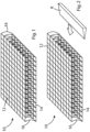
Figure 1 illustrates a knitted dual layered fabric with connecting yarns extending between the two layers; -
Figure 2 illustrates the layered fabric ofFigure 1 and showing a knife positioned to cut through the middle of the connecting yarns to form two surgical fabrics according to the invention; -
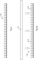
Figure 3 illustrates a cross sectional view ofFigure 2 ; -
Figure 4 illustrates a self adhering surgical fabric according to the invention as formed from either half of the cut layered fabric ofFigures 2 and3 ; -
Figure 5 illustrates a cross sectional view ofFigure 4 ; -
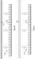
Figure 6a illustrates the surgical fabric ofFigures 4 and5 with a flat hot platen tool being advanced towards the tops of the connecting yarns to form heads thereon; -
Figure 6b illustrates the surgical fabric with a hot platen tool with spike shaped depressions being advanced towards the tops of the yarns; -
Figure 6c illustrates the surgical fabric with a hot platen tool with dome-shaped depressions being advanced towards the tops of the yarns; and -
Figure 7 illustrates a cross sectional view of the surgical fabric with protruding connecting yarns having a dome or mushroom shaped head or barb formed at the free end of each connecting yarn. - Referring now to the accompanying drawings there is illustrated a layered fabric, generally indicated as (10), which comprises a first layer of material (12) and a second layer of material (14) in parallel spaced relationship to one another, and connected together by an array of connecting yarns (16) extending between the layers (12), (14). The connecting yarns (16) may extend perpendicularly from one or both of the layers (12), (14) or may extend at an angle to one or both of the layers (12), (14). The first layer (12) and/or the second layer (14) may be formed as a woven material or as a knitted material, or any other suitable construction. A woven material is produced by orienting yarns along both X and Y axes, that is by arranging a series of warp yarns adjacent one another and interspersing or interweaving weft yarns. The resulting material often tends to offer minimal compliance, depending on the yarn or combination of yarns utilised. It will be appreciated that the physical characteristics of the yarns and the weave may be varied to provided particular desired characteristics such as flexibility, porosity, etc.
- The first and/or second layers of material (12), (14) may be constructed from monofilament, multifilament or ring spun yarns of regenerated silk, nylon/high tension nylon, PET/high tension PET, UHMWPE, LCP (liquid crystal polymer) or any other suitable material. Where a multifilament is utilised this may be heat set in a twisted condition or not. The layers of material (12), (14) may also be constructed from resorbable polymers, for example PLA, PLLA, PGA, PLGA, Polycaprolactone or Polydioxanone. In a preferred embodiment illustrated the yarns utilised in the construction of the layers of material (12), (14) can range from 5 to 500 denier.
- Referring to
Figures 2 and3 , once the layered fabric (10) has been constructed, the method according to the present invention then involves separating the first layer of material (12) from the second layer of material (14) by cutting through the connecting yarns (16) such that a portion of each connecting yarn (16) remains attached to both the first layer (12) and to the second layer (14), either of which then define a self adhering surgical fabric (110) according to the invention and as illustrated inFigures 4 to 7 . In a preferred embodiment of the method a knife K, which may be heated, is used to cut through the connecting yarns (16) to form the two portions of self adhering fabric (110). - The self adhering surgical fabric (110) comprises a substrate (112) from which projects an array of yarns (116) which function as anchors or hooks which allow the surgical fabric (110) to self adhere to tissue or the like, thereby avoiding the requirement for suturing or otherwise securing the self adhering fabric (110) into position at a surgical site or the like. Traditionally such surgical meshes are required to be sutured or adhered into place, and by avoiding this additional step the self adhering surgical fabric (110) of the present invention reduces the time and complexity of the surgical operation and as a result can improve patient healing response. Potential surgical applications for the self adhering surgical fabric (110) include fixation to treat pelvic organ prolapse, wound closure, surgical incision closure, vessel puncture site closure, AAA/TAA endovascular grafts to inhibit migration, and integration into oesophageal or biliary covered stents to inhibit migration.
- In order to improve the self adherence of the surgical fabric (110) the free end of each of the connecting yarns (116) may be shaped to define a head or barb (118) which will increase the grip generated when the yarns (116) engage with the target tissue. The heads (118) may be formed simultaneously with cutting of the connecting yarns (16) by the knife K, which may be heated in order to partially melt the free end of each connecting yarn (16) as it is cut, thereby deforming the free end of the connecting yarn (16) to form the head (118). Alternatively as illustrated in
Figures 6a ,6b and 6c the method of forming the self adhering surgical fabric (110) of the present invention may also include the step of engaging a hot platen P1, P2 or P3 against the free end of each of the yarns (116) in order to melt and deform the free end to form the head (118). The platen P1 comprises a flat contact surface to engage against the yarns (116), while the platens P2 and P3 incorporate a spiked and a domed contact surface in order to generate a barbed or mushroom shaped head (118) when pressed into engagement with the yarns (116). It will of course be appreciated that any other functional alternative may be employed in order to form the shaped heads (118). - It will also be appreciated that the two halves of the layered fabric (10) once separated from one another by the action of the knife K cutting the connecting yarns (116), can be utilised as a self adhering surgical fabric (110) according to the invention.
Claims (15)
- A method of manufacturing a self-adhering surgical fabric (10; 110), comprising the steps of:a) forming a first layer of material (12; 112);b) forming a second layer of material (14);c) joining the first and second layers of material (12; 112, 14) in spaced parallel relationship to one another with an array of connecting yarns (16; 116) extending to the first and second layers of material; andd) cutting the connecting yarns (16; 116) to separate the first layer of material (12; 112) from the second layer of material (14) such that both of the first and second layers of material (12; 112, 14) retain a respective first and second portion of each connecting yarn (16; 116) projecting from a face of the respective first and second layers of material (12; 112, 14) to respective first and second free ends, wherein the free ends formed after cutting the connecting yarns are configured to function as anchors or hooks to self-adhere the respective first and second layers of material to tissue.
- The method according to claim 1, comprising weaving or knitting the first and second layers of material (12; 112, 14).
- The method according to any preceding claim, comprising cutting the connecting yarns (16; 116) using heat and/or mechanical action; and optionally cutting the connecting yarns using a hot knife.
- The method according to any preceding claim, comprising forming the respective first and second free ends as first and second heads (118) that are configured to function as the anchors or hooks to self-adhere the respective first and second layers of material to tissue.
- The method according to claim 4, comprising forming the first and second heads (118) simultaneously with cutting the connecting yarn.
- The method according to any preceding claim, comprising orienting the connecting yarns (16; 116) perpendicularly to the first and second layers of material (12; 112, 14).
- The method according to any preceding claim, comprising orienting the connecting yarns (16; 116) non-perpendicularly to the first and second layers of material (12; 112, 14).
- The method according to any preceding claim, comprising interweaving the connecting yarn (16; 116) with the first and second layers of material (12; 112, 14).
- The method according to any preceding claim comprising, forming the first and second layers of material (12; 112, 14) from one or more polymers.
- A self-adhering surgical fabric (10; 110) comprising a layer of a woven material or a knitted material (12; 112, 14) having an array of yarns (16; 116) projecting from a face of the layer of woven or knitted material (12; 112, 14) to an array of mushroom-shaped heads (118), that are configured to function as anchors or hooks to self-adhere the layer of woven or knitted material comprising the surgical fabric to tissue.
- The self-adhering surgical fabric according to claim 10, wherein the layer of woven or knitted material (12; 112, 14) is formed from monofilament, multifilament or ring spun yarns of regenerated silk, nylon/high tension nylon, PET/high tension PET, UHMWPE, or LCP (liquid crystal polymer).
- The self-adhering surgical fabric according to any of claims 10 or 11, wherein the layer of woven or knitted material (12; 112, 14) is constructed from yarns of resorbable polymers selected from the group of PLA, PLLA, PGA, PLGA, Polycaprolactone or Polydioxanone.
- The self-adhering surgical fabric according to any of claims 10 to 12, wherein the yarns comprising the layer of woven or knitted material (12; 112, 14) have a range of 5 denier to 500 denier.
- The self-adhering surgical fabric according to any of claims 10 to 13, wherein yarns (16; 116) projecting from the layer of woven or knitted material (12; 112, 14) to the array of mushroom-shaped heads (118) are oriented either perpendicularly or non-perpendicularly to the face of the layer of woven or knitted material (12; 112, 14).
- The self-adhering surgical fabric according to any of claims 10 to 14, wherein layer of woven or knitted material (12; 112, 14) are a multifilament that is heat set before being woven or knitted into the layer of woven or knitted material (12; 112, 14).
Applications Claiming Priority (2)
| Application Number | Priority Date | Filing Date | Title |
|---|---|---|---|
| IES20170262 | 2017-12-21 | ||
| PCT/EP2018/086241 WO2019122154A1 (en) | 2017-12-21 | 2018-12-20 | A self adhering surgical fabric and method of manufacturing same |
Publications (2)
| Publication Number | Publication Date |
|---|---|
| EP3727490A1 EP3727490A1 (en) | 2020-10-28 |
| EP3727490B1 true EP3727490B1 (en) | 2025-07-02 |
Family
ID=66993079
Family Applications (1)
| Application Number | Title | Priority Date | Filing Date |
|---|---|---|---|
| EP18826671.2A Active EP3727490B1 (en) | 2017-12-21 | 2018-12-20 | A self adhering surgical fabric and method of manufacturing same |
Country Status (2)
| Country | Link |
|---|---|
| EP (1) | EP3727490B1 (en) |
| WO (1) | WO2019122154A1 (en) |
Families Citing this family (1)
| Publication number | Priority date | Publication date | Assignee | Title |
|---|---|---|---|---|
| FR3129158B1 (en) * | 2021-11-15 | 2023-11-10 | Michelin & Cie | METHOD FOR CUTTING A THREE-DIMENSIONAL FABRIC COMPRISING TWO LAYERS OF FABRIC CONNECTED TO EACH OTHER BY GUARDS |
Citations (1)
| Publication number | Priority date | Publication date | Assignee | Title |
|---|---|---|---|---|
| EP3628763A1 (en) * | 2018-09-27 | 2020-04-01 | Sofradim Production | Bioresorbable knit for hernia repair and method for manufacturing the same |
Family Cites Families (4)
| Publication number | Priority date | Publication date | Assignee | Title |
|---|---|---|---|---|
| US1313037A (en) * | 1919-08-12 | Elastic fabric | ||
| GB1123575A (en) * | 1965-10-14 | 1968-08-14 | Schlegel Mfg Co | Pile fabric and articles made therefrom |
| AU3242693A (en) * | 1991-12-06 | 1993-06-28 | Kensey Nash Corporation | Pads, methods of making, and methods of use for wound dressing, surgical reinforcement and hemostasis promotion |
| DK2434984T3 (en) * | 2009-05-30 | 2016-05-30 | Inst Für Textil Und Faserforschung Denkendorf Stiftung Des Öffentlichen Rechts Deutsche | medical Product |
-
2018
- 2018-12-20 EP EP18826671.2A patent/EP3727490B1/en active Active
- 2018-12-20 WO PCT/EP2018/086241 patent/WO2019122154A1/en not_active Ceased
Patent Citations (1)
| Publication number | Priority date | Publication date | Assignee | Title |
|---|---|---|---|---|
| EP3628763A1 (en) * | 2018-09-27 | 2020-04-01 | Sofradim Production | Bioresorbable knit for hernia repair and method for manufacturing the same |
Also Published As
| Publication number | Publication date |
|---|---|
| EP3727490A1 (en) | 2020-10-28 |
| WO2019122154A1 (en) | 2019-06-27 |
Similar Documents
| Publication | Publication Date | Title |
|---|---|---|
| US11925543B2 (en) | Barbed prosthetic knit and hernia repair mesh made therefrom as well as process for making said prosthetic knit | |
| JP5933539B2 (en) | Marked prosthesis | |
| EP2231062B1 (en) | Implant for parastomal hernia | |
| US10577731B2 (en) | Knit with strips without barbs, method of making same and prostheses made from said knit | |
| US10195011B2 (en) | Knit with zones without barbs, method of making same and prostheses obtained therefrom | |
| US20220346930A1 (en) | Prosthesis for hernia repair | |
| EP3934575B1 (en) | Textured medical textiles | |
| US20210140078A1 (en) | Two-sides gripping knit | |
| US9510927B2 (en) | Method of making a knit with barbs | |
| WO2019122154A1 (en) | A self adhering surgical fabric and method of manufacturing same | |
| EP3895658B1 (en) | Surgical textile with barbs and loops and process for manufacturing the same | |
| EP4376723B1 (en) | Suture having adaptable surface characteristics | |
| AU2014203792B2 (en) | Implant for parastomal hernia | |
| US20250375282A1 (en) | Implantable prosthesis with self-fixating grips |
Legal Events
| Date | Code | Title | Description |
|---|---|---|---|
| STAA | Information on the status of an ep patent application or granted ep patent |
Free format text: STATUS: UNKNOWN |
|
| STAA | Information on the status of an ep patent application or granted ep patent |
Free format text: STATUS: THE INTERNATIONAL PUBLICATION HAS BEEN MADE |
|
| PUAI | Public reference made under article 153(3) epc to a published international application that has entered the european phase |
Free format text: ORIGINAL CODE: 0009012 |
|
| STAA | Information on the status of an ep patent application or granted ep patent |
Free format text: STATUS: REQUEST FOR EXAMINATION WAS MADE |
|
| 17P | Request for examination filed |
Effective date: 20200720 |
|
| AK | Designated contracting states |
Kind code of ref document: A1 Designated state(s): AL AT BE BG CH CY CZ DE DK EE ES FI FR GB GR HR HU IE IS IT LI LT LU LV MC MK MT NL NO PL PT RO RS SE SI SK SM TR |
|
| AX | Request for extension of the european patent |
Extension state: BA ME |
|
| DAV | Request for validation of the european patent (deleted) | ||
| DAX | Request for extension of the european patent (deleted) | ||
| STAA | Information on the status of an ep patent application or granted ep patent |
Free format text: STATUS: EXAMINATION IS IN PROGRESS |
|
| 17Q | First examination report despatched |
Effective date: 20220412 |
|
| GRAP | Despatch of communication of intention to grant a patent |
Free format text: ORIGINAL CODE: EPIDOSNIGR1 |
|
| STAA | Information on the status of an ep patent application or granted ep patent |
Free format text: STATUS: GRANT OF PATENT IS INTENDED |
|
| GRAS | Grant fee paid |
Free format text: ORIGINAL CODE: EPIDOSNIGR3 |
|
| GRAA | (expected) grant |
Free format text: ORIGINAL CODE: 0009210 |
|
| STAA | Information on the status of an ep patent application or granted ep patent |
Free format text: STATUS: THE PATENT HAS BEEN GRANTED |
|
| INTG | Intention to grant announced |
Effective date: 20250514 |
|
| AK | Designated contracting states |
Kind code of ref document: B1 Designated state(s): AL AT BE BG CH CY CZ DE DK EE ES FI FR GB GR HR HU IE IS IT LI LT LU LV MC MK MT NL NO PL PT RO RS SE SI SK SM TR |
|
| REG | Reference to a national code |
Ref country code: GB Ref legal event code: FG4D |
|
| REG | Reference to a national code |
Ref country code: CH Ref legal event code: EP |
|
| REG | Reference to a national code |
Ref country code: DE Ref legal event code: R096 Ref document number: 602018083259 Country of ref document: DE |
|
| REG | Reference to a national code |
Ref country code: IE Ref legal event code: FG4D |
|
| REG | Reference to a national code |
Ref country code: NL Ref legal event code: MP Effective date: 20250702 |
|
| PG25 | Lapsed in a contracting state [announced via postgrant information from national office to epo] |
Ref country code: PT Free format text: LAPSE BECAUSE OF FAILURE TO SUBMIT A TRANSLATION OF THE DESCRIPTION OR TO PAY THE FEE WITHIN THE PRESCRIBED TIME-LIMIT Effective date: 20251103 |
|
| PG25 | Lapsed in a contracting state [announced via postgrant information from national office to epo] |
Ref country code: NL Free format text: LAPSE BECAUSE OF FAILURE TO SUBMIT A TRANSLATION OF THE DESCRIPTION OR TO PAY THE FEE WITHIN THE PRESCRIBED TIME-LIMIT Effective date: 20250702 |
|
| REG | Reference to a national code |
Ref country code: AT Ref legal event code: MK05 Ref document number: 1808543 Country of ref document: AT Kind code of ref document: T Effective date: 20250702 |
|
| PG25 | Lapsed in a contracting state [announced via postgrant information from national office to epo] |
Ref country code: IS Free format text: LAPSE BECAUSE OF FAILURE TO SUBMIT A TRANSLATION OF THE DESCRIPTION OR TO PAY THE FEE WITHIN THE PRESCRIBED TIME-LIMIT Effective date: 20251102 |
|
| PG25 | Lapsed in a contracting state [announced via postgrant information from national office to epo] |
Ref country code: NO Free format text: LAPSE BECAUSE OF FAILURE TO SUBMIT A TRANSLATION OF THE DESCRIPTION OR TO PAY THE FEE WITHIN THE PRESCRIBED TIME-LIMIT Effective date: 20251002 |
|
| REG | Reference to a national code |
Ref country code: LT Ref legal event code: MG9D |
|
| PG25 | Lapsed in a contracting state [announced via postgrant information from national office to epo] |
Ref country code: AT Free format text: LAPSE BECAUSE OF FAILURE TO SUBMIT A TRANSLATION OF THE DESCRIPTION OR TO PAY THE FEE WITHIN THE PRESCRIBED TIME-LIMIT Effective date: 20250702 |
|
| PG25 | Lapsed in a contracting state [announced via postgrant information from national office to epo] |
Ref country code: FI Free format text: LAPSE BECAUSE OF FAILURE TO SUBMIT A TRANSLATION OF THE DESCRIPTION OR TO PAY THE FEE WITHIN THE PRESCRIBED TIME-LIMIT Effective date: 20250702 |
|
| PG25 | Lapsed in a contracting state [announced via postgrant information from national office to epo] |
Ref country code: HR Free format text: LAPSE BECAUSE OF FAILURE TO SUBMIT A TRANSLATION OF THE DESCRIPTION OR TO PAY THE FEE WITHIN THE PRESCRIBED TIME-LIMIT Effective date: 20250702 |
|
| PG25 | Lapsed in a contracting state [announced via postgrant information from national office to epo] |
Ref country code: GR Free format text: LAPSE BECAUSE OF FAILURE TO SUBMIT A TRANSLATION OF THE DESCRIPTION OR TO PAY THE FEE WITHIN THE PRESCRIBED TIME-LIMIT Effective date: 20251003 |
|
| PG25 | Lapsed in a contracting state [announced via postgrant information from national office to epo] |
Ref country code: CZ Free format text: LAPSE BECAUSE OF FAILURE TO SUBMIT A TRANSLATION OF THE DESCRIPTION OR TO PAY THE FEE WITHIN THE PRESCRIBED TIME-LIMIT Effective date: 20250702 Ref country code: SE Free format text: LAPSE BECAUSE OF FAILURE TO SUBMIT A TRANSLATION OF THE DESCRIPTION OR TO PAY THE FEE WITHIN THE PRESCRIBED TIME-LIMIT Effective date: 20250702 |
|
| PG25 | Lapsed in a contracting state [announced via postgrant information from national office to epo] |
Ref country code: LV Free format text: LAPSE BECAUSE OF FAILURE TO SUBMIT A TRANSLATION OF THE DESCRIPTION OR TO PAY THE FEE WITHIN THE PRESCRIBED TIME-LIMIT Effective date: 20250702 |
|
| PG25 | Lapsed in a contracting state [announced via postgrant information from national office to epo] |
Ref country code: PL Free format text: LAPSE BECAUSE OF FAILURE TO SUBMIT A TRANSLATION OF THE DESCRIPTION OR TO PAY THE FEE WITHIN THE PRESCRIBED TIME-LIMIT Effective date: 20250702 Ref country code: BG Free format text: LAPSE BECAUSE OF FAILURE TO SUBMIT A TRANSLATION OF THE DESCRIPTION OR TO PAY THE FEE WITHIN THE PRESCRIBED TIME-LIMIT Effective date: 20250702 |
|
| PG25 | Lapsed in a contracting state [announced via postgrant information from national office to epo] |
Ref country code: RS Free format text: LAPSE BECAUSE OF FAILURE TO SUBMIT A TRANSLATION OF THE DESCRIPTION OR TO PAY THE FEE WITHIN THE PRESCRIBED TIME-LIMIT Effective date: 20251002 |
|
| PG25 | Lapsed in a contracting state [announced via postgrant information from national office to epo] |
Ref country code: ES Free format text: LAPSE BECAUSE OF FAILURE TO SUBMIT A TRANSLATION OF THE DESCRIPTION OR TO PAY THE FEE WITHIN THE PRESCRIBED TIME-LIMIT Effective date: 20250702 |
|
| PG25 | Lapsed in a contracting state [announced via postgrant information from national office to epo] |
Ref country code: RO Free format text: LAPSE BECAUSE OF FAILURE TO SUBMIT A TRANSLATION OF THE DESCRIPTION OR TO PAY THE FEE WITHIN THE PRESCRIBED TIME-LIMIT Effective date: 20250702 |
|
| PG25 | Lapsed in a contracting state [announced via postgrant information from national office to epo] |
Ref country code: SM Free format text: LAPSE BECAUSE OF FAILURE TO SUBMIT A TRANSLATION OF THE DESCRIPTION OR TO PAY THE FEE WITHIN THE PRESCRIBED TIME-LIMIT Effective date: 20250702 |
|
| PGFP | Annual fee paid to national office [announced via postgrant information from national office to epo] |
Ref country code: GB Payment date: 20260129 Year of fee payment: 8 |
|
| PG25 | Lapsed in a contracting state [announced via postgrant information from national office to epo] |
Ref country code: DK Free format text: LAPSE BECAUSE OF FAILURE TO SUBMIT A TRANSLATION OF THE DESCRIPTION OR TO PAY THE FEE WITHIN THE PRESCRIBED TIME-LIMIT Effective date: 20250702 |
|
| PG25 | Lapsed in a contracting state [announced via postgrant information from national office to epo] |
Ref country code: IT Free format text: LAPSE BECAUSE OF FAILURE TO SUBMIT A TRANSLATION OF THE DESCRIPTION OR TO PAY THE FEE WITHIN THE PRESCRIBED TIME-LIMIT Effective date: 20250702 |
|
| PG25 | Lapsed in a contracting state [announced via postgrant information from national office to epo] |
Ref country code: EE Free format text: LAPSE BECAUSE OF FAILURE TO SUBMIT A TRANSLATION OF THE DESCRIPTION OR TO PAY THE FEE WITHIN THE PRESCRIBED TIME-LIMIT Effective date: 20250702 Ref country code: SK Free format text: LAPSE BECAUSE OF FAILURE TO SUBMIT A TRANSLATION OF THE DESCRIPTION OR TO PAY THE FEE WITHIN THE PRESCRIBED TIME-LIMIT Effective date: 20250702 |
|
| PLBE | No opposition filed within time limit |
Free format text: ORIGINAL CODE: 0009261 |
|
| STAA | Information on the status of an ep patent application or granted ep patent |
Free format text: STATUS: NO OPPOSITION FILED WITHIN TIME LIMIT |