EP3727147B1 - Vorrichtung und verfahren zur registrierung von gesichtsmarkierungen für ein chirurgisches navigationssystem - Google Patents
Vorrichtung und verfahren zur registrierung von gesichtsmarkierungen für ein chirurgisches navigationssystem Download PDFInfo
- Publication number
- EP3727147B1 EP3727147B1 EP18845358.3A EP18845358A EP3727147B1 EP 3727147 B1 EP3727147 B1 EP 3727147B1 EP 18845358 A EP18845358 A EP 18845358A EP 3727147 B1 EP3727147 B1 EP 3727147B1
- Authority
- EP
- European Patent Office
- Prior art keywords
- sensor
- target area
- sensor array
- registration
- patient
- Prior art date
- Legal status (The legal status is an assumption and is not a legal conclusion. Google has not performed a legal analysis and makes no representation as to the accuracy of the status listed.)
- Active
Links
Images


Classifications
-
- A—HUMAN NECESSITIES
- A61—MEDICAL OR VETERINARY SCIENCE; HYGIENE
- A61B—DIAGNOSIS; SURGERY; IDENTIFICATION
- A61B34/00—Computer-aided surgery; Manipulators or robots specially adapted for use in surgery
- A61B34/20—Surgical navigation systems; Devices for tracking or guiding surgical instruments, e.g. for frameless stereotaxis
-
- A—HUMAN NECESSITIES
- A61—MEDICAL OR VETERINARY SCIENCE; HYGIENE
- A61B—DIAGNOSIS; SURGERY; IDENTIFICATION
- A61B17/00—Surgical instruments, devices or methods
- A61B17/24—Surgical instruments, devices or methods for use in the oral cavity, larynx, bronchial passages or nose; Tongue scrapers
-
- A—HUMAN NECESSITIES
- A61—MEDICAL OR VETERINARY SCIENCE; HYGIENE
- A61B—DIAGNOSIS; SURGERY; IDENTIFICATION
- A61B90/00—Instruments, implements or accessories specially adapted for surgery or diagnosis and not covered by any of the groups A61B1/00 - A61B50/00, e.g. for luxation treatment or for protecting wound edges
- A61B90/10—Instruments, implements or accessories specially adapted for surgery or diagnosis and not covered by any of the groups A61B1/00 - A61B50/00, e.g. for luxation treatment or for protecting wound edges for stereotaxic surgery, e.g. frame-based stereotaxis
- A61B90/11—Instruments, implements or accessories specially adapted for surgery or diagnosis and not covered by any of the groups A61B1/00 - A61B50/00, e.g. for luxation treatment or for protecting wound edges for stereotaxic surgery, e.g. frame-based stereotaxis with guides for needles or instruments, e.g. arcuate slides or ball joints
- A61B90/13—Instruments, implements or accessories specially adapted for surgery or diagnosis and not covered by any of the groups A61B1/00 - A61B50/00, e.g. for luxation treatment or for protecting wound edges for stereotaxic surgery, e.g. frame-based stereotaxis with guides for needles or instruments, e.g. arcuate slides or ball joints guided by light, e.g. laser pointers
-
- A—HUMAN NECESSITIES
- A61—MEDICAL OR VETERINARY SCIENCE; HYGIENE
- A61B—DIAGNOSIS; SURGERY; IDENTIFICATION
- A61B90/00—Instruments, implements or accessories specially adapted for surgery or diagnosis and not covered by any of the groups A61B1/00 - A61B50/00, e.g. for luxation treatment or for protecting wound edges
- A61B90/50—Supports for surgical instruments, e.g. articulated arms
-
- A—HUMAN NECESSITIES
- A61—MEDICAL OR VETERINARY SCIENCE; HYGIENE
- A61B—DIAGNOSIS; SURGERY; IDENTIFICATION
- A61B17/00—Surgical instruments, devices or methods
- A61B2017/00681—Aspects not otherwise provided for
- A61B2017/00725—Calibration or performance testing
-
- A—HUMAN NECESSITIES
- A61—MEDICAL OR VETERINARY SCIENCE; HYGIENE
- A61B—DIAGNOSIS; SURGERY; IDENTIFICATION
- A61B17/00—Surgical instruments, devices or methods
- A61B17/24—Surgical instruments, devices or methods for use in the oral cavity, larynx, bronchial passages or nose; Tongue scrapers
- A61B2017/246—Surgical instruments, devices or methods for use in the oral cavity, larynx, bronchial passages or nose; Tongue scrapers for cleaning of the nose
-
- A—HUMAN NECESSITIES
- A61—MEDICAL OR VETERINARY SCIENCE; HYGIENE
- A61B—DIAGNOSIS; SURGERY; IDENTIFICATION
- A61B34/00—Computer-aided surgery; Manipulators or robots specially adapted for use in surgery
- A61B34/20—Surgical navigation systems; Devices for tracking or guiding surgical instruments, e.g. for frameless stereotaxis
- A61B2034/2046—Tracking techniques
- A61B2034/2048—Tracking techniques using an accelerometer or inertia sensor
-
- A—HUMAN NECESSITIES
- A61—MEDICAL OR VETERINARY SCIENCE; HYGIENE
- A61B—DIAGNOSIS; SURGERY; IDENTIFICATION
- A61B34/00—Computer-aided surgery; Manipulators or robots specially adapted for use in surgery
- A61B34/20—Surgical navigation systems; Devices for tracking or guiding surgical instruments, e.g. for frameless stereotaxis
- A61B2034/2046—Tracking techniques
- A61B2034/2051—Electromagnetic tracking systems
-
- A—HUMAN NECESSITIES
- A61—MEDICAL OR VETERINARY SCIENCE; HYGIENE
- A61B—DIAGNOSIS; SURGERY; IDENTIFICATION
- A61B34/00—Computer-aided surgery; Manipulators or robots specially adapted for use in surgery
- A61B34/20—Surgical navigation systems; Devices for tracking or guiding surgical instruments, e.g. for frameless stereotaxis
- A61B2034/2046—Tracking techniques
- A61B2034/2055—Optical tracking systems
-
- A—HUMAN NECESSITIES
- A61—MEDICAL OR VETERINARY SCIENCE; HYGIENE
- A61B—DIAGNOSIS; SURGERY; IDENTIFICATION
- A61B34/00—Computer-aided surgery; Manipulators or robots specially adapted for use in surgery
- A61B34/20—Surgical navigation systems; Devices for tracking or guiding surgical instruments, e.g. for frameless stereotaxis
- A61B2034/2046—Tracking techniques
- A61B2034/2063—Acoustic tracking systems, e.g. using ultrasound
-
- A—HUMAN NECESSITIES
- A61—MEDICAL OR VETERINARY SCIENCE; HYGIENE
- A61B—DIAGNOSIS; SURGERY; IDENTIFICATION
- A61B34/00—Computer-aided surgery; Manipulators or robots specially adapted for use in surgery
- A61B34/20—Surgical navigation systems; Devices for tracking or guiding surgical instruments, e.g. for frameless stereotaxis
- A61B2034/2046—Tracking techniques
- A61B2034/2065—Tracking using image or pattern recognition
-
- A—HUMAN NECESSITIES
- A61—MEDICAL OR VETERINARY SCIENCE; HYGIENE
- A61B—DIAGNOSIS; SURGERY; IDENTIFICATION
- A61B34/00—Computer-aided surgery; Manipulators or robots specially adapted for use in surgery
- A61B34/20—Surgical navigation systems; Devices for tracking or guiding surgical instruments, e.g. for frameless stereotaxis
- A61B2034/2068—Surgical navigation systems; Devices for tracking or guiding surgical instruments, e.g. for frameless stereotaxis using pointers, e.g. pointers having reference marks for determining coordinates of body points
-
- A—HUMAN NECESSITIES
- A61—MEDICAL OR VETERINARY SCIENCE; HYGIENE
- A61B—DIAGNOSIS; SURGERY; IDENTIFICATION
- A61B34/00—Computer-aided surgery; Manipulators or robots specially adapted for use in surgery
- A61B34/20—Surgical navigation systems; Devices for tracking or guiding surgical instruments, e.g. for frameless stereotaxis
- A61B2034/2072—Reference field transducer attached to an instrument or patient
-
- A—HUMAN NECESSITIES
- A61—MEDICAL OR VETERINARY SCIENCE; HYGIENE
- A61B—DIAGNOSIS; SURGERY; IDENTIFICATION
- A61B90/00—Instruments, implements or accessories specially adapted for surgery or diagnosis and not covered by any of the groups A61B1/00 - A61B50/00, e.g. for luxation treatment or for protecting wound edges
- A61B90/36—Image-producing devices or illumination devices not otherwise provided for
- A61B2090/363—Use of fiducial points
-
- A—HUMAN NECESSITIES
- A61—MEDICAL OR VETERINARY SCIENCE; HYGIENE
- A61B—DIAGNOSIS; SURGERY; IDENTIFICATION
- A61B90/00—Instruments, implements or accessories specially adapted for surgery or diagnosis and not covered by any of the groups A61B1/00 - A61B50/00, e.g. for luxation treatment or for protecting wound edges
- A61B90/36—Image-producing devices or illumination devices not otherwise provided for
- A61B2090/364—Correlation of different images or relation of image positions in respect to the body
- A61B2090/365—Correlation of different images or relation of image positions in respect to the body augmented reality, i.e. correlating a live optical image with another image
-
- A—HUMAN NECESSITIES
- A61—MEDICAL OR VETERINARY SCIENCE; HYGIENE
- A61B—DIAGNOSIS; SURGERY; IDENTIFICATION
- A61B90/00—Instruments, implements or accessories specially adapted for surgery or diagnosis and not covered by any of the groups A61B1/00 - A61B50/00, e.g. for luxation treatment or for protecting wound edges
- A61B90/36—Image-producing devices or illumination devices not otherwise provided for
- A61B90/37—Surgical systems with images on a monitor during operation
- A61B2090/373—Surgical systems with images on a monitor during operation using light, e.g. by using optical scanners
-
- A—HUMAN NECESSITIES
- A61—MEDICAL OR VETERINARY SCIENCE; HYGIENE
- A61B—DIAGNOSIS; SURGERY; IDENTIFICATION
- A61B90/00—Instruments, implements or accessories specially adapted for surgery or diagnosis and not covered by any of the groups A61B1/00 - A61B50/00, e.g. for luxation treatment or for protecting wound edges
- A61B90/36—Image-producing devices or illumination devices not otherwise provided for
- A61B90/37—Surgical systems with images on a monitor during operation
- A61B2090/376—Surgical systems with images on a monitor during operation using X-rays, e.g. fluoroscopy
- A61B2090/3762—Surgical systems with images on a monitor during operation using X-rays, e.g. fluoroscopy using computed tomography systems [CT]
-
- A—HUMAN NECESSITIES
- A61—MEDICAL OR VETERINARY SCIENCE; HYGIENE
- A61B—DIAGNOSIS; SURGERY; IDENTIFICATION
- A61B2562/00—Details of sensors; Constructional details of sensor housings or probes; Accessories for sensors
- A61B2562/02—Details of sensors specially adapted for in-vivo measurements
- A61B2562/0257—Proximity sensors
-
- A—HUMAN NECESSITIES
- A61—MEDICAL OR VETERINARY SCIENCE; HYGIENE
- A61B—DIAGNOSIS; SURGERY; IDENTIFICATION
- A61B5/00—Measuring for diagnostic purposes; Identification of persons
- A61B5/06—Devices, other than using radiation, for detecting or locating foreign bodies ; Determining position of diagnostic devices within or on the body of the patient
- A61B5/061—Determining position of a probe within the body employing means separate from the probe, e.g. sensing internal probe position employing impedance electrodes on the surface of the body
Definitions
- an anatomical passageway in a patient. This may include dilation of ostia of paranasal sinuses (e.g., to treat sinusitis), dilation of the larynx, dilation of the Eustachian tube, dilation of other passageways within the ear, nose, or throat, etc.
- One method of dilating anatomical passageways includes using a guide wire and catheter to position an inflatable balloon within the anatomical passageway, then inflating the balloon with a fluid (e.g., saline) to dilate the anatomical passageway.
- a fluid e.g., saline
- the expandable balloon may be positioned within an ostium at a paranasal sinus and then be inflated, to thereby dilate the ostium by remodeling the bone adjacent to the ostium, without requiring incision of the mucosa or removal of any bone.
- the dilated ostium may then allow for improved drainage from and ventilation of the affected paranasal sinus.
- a system that may be used to perform such procedures may be provided in accordance with the teachings of U.S. Pub. No. 2011/0004057, entitled “Systems and Methods for Transnasal Dilation of Passageways in the Ear, Nose or Throat," published January 6, 2011 .
- An example of such a system is the Relieva° Spin Balloon Sinuplasty TM System by Acclarent, Inc. of Irvine, California.
- Image-guided surgery is a technique where a computer is used to obtain a real-time correlation of the location of an instrument that has been inserted into a patient's body to a set of preoperatively obtained images (e.g., a CT or MRI scan, 3-D map, etc.), such that the computer system may superimpose the current location of the instrument on the preoperatively obtained images.
- a digital tomographic scan e.g., CT or MRI, 3-D map, etc.
- a specially programmed computer is then used to convert the digital tomographic scan data into a digital map.
- special instruments having sensors (e.g., electromagnetic coils that emit electromagnetic fields and/or are responsive to externally generated electromagnetic fields) mounted thereon are used to perform the procedure while the sensors send data to the computer indicating the current position of each surgical instrument.
- the computer correlates the data it receives from the instrument-mounted sensors with the digital map that was created from the preoperative tomographic scan.
- the tomographic scan images are displayed on a video monitor along with an indicator (e.g., crosshairs or an illuminated dot, etc.) showing the real-time position of each surgical instrument relative to the anatomical structures shown in the scan images.
- an indicator e.g., crosshairs or an illuminated dot, etc.
- IGS systems An example of an electromagnetic IGS systems that may be used in ENT and sinus surgery is the CARTOR 3 System by Biosense-Webster, Inc., of Irvine, California.
- FESS functional endoscopic sinus surgery
- balloon sinuplasty balloon sinuplasty
- other ENT procedures the use of IGS systems allows the surgeon to achieve more precise movement and positioning of the surgical instruments than can be achieved by viewing through an endoscope alone.
- IGS systems may be particularly useful during performance of FESS, balloon sinuplasty, and/or other ENT procedures where anatomical landmarks are not present or are difficult to visualize endoscopically.
- One function that may be performed by an IGS system is obtaining a reference point that can be used to correlate various preoperatively obtained images with a patient's actual position during a procedure. This act may be referred to as patient registration.
- Patient registration is conventionally performed by using a positionally tracked instrument (e.g., a guidewire whose tip position may be detected in three-dimensional space) to trace the area of a patient that will be affected by the procedure.
- a positionally tracked guidewire or other tool may be used to trace or touch one or more positions on a patient's face.
- a positional tracking system will register that point in three-dimensional space and, using a number of registered points, determine the position of the affected area in three-dimensional space. Once the affected area is fully mapped or registered, it can be correlated with preoperative images in order to provide a seamless IGS experience across varying types of preoperative images during the performance of the procedure. Performing patient registration in this manner is both time consuming and error prone, due to the number of touch points required for some procedures and the relative inaccuracy of pressing a flexible guidewire tip against the non-rigid surface of a patient's face.
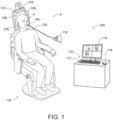
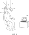
- FIG. 1 shows an exemplary IGS navigation system (100) enabling an ENT procedure to be performed using image guidance.
- IGS navigation system (100) is used during a procedure where dilation instrument assembly (10) is used to dilate the ostium of a paranasal sinus; or to dilate some other anatomical passageway (e.g., within the ear, nose, or throat, etc.).
- IGS navigation system (100) may be constructed and operable in accordance with at least some of the teachings of U.S. Pat. No. 8,702,626, entitled "Guidewires for Performing Image Guided Procedures," issued April 22, 2014 ; U.S. Pat. No.
- IGS navigation system (100) of the present example comprises a field generator assembly (101), which comprises set of magnetic field generators (106) that are integrated into a horseshoe-shaped frame (104). Field generators (106) are operable to generate alternating magnetic fields of different frequencies around the head of the patient. Field generators (106) thereby enable tracking of the position of a navigation guidewire (130) that is inserted into the head of the patient.
- a navigation guidewire (130) that is inserted into the head of the patient.
- Various suitable components that may be used to form and drive field generators (106) will be apparent to those of ordinary skill in the art in view of the teachings herein.
- frame (104) is mounted to a chair (118), with the patient (P) being seated in the chair (118) such that frame (104) is located adjacent to the head (H) of the patient (P).
- chair (118) and/or field generator assembly (101) may be configured and operable in accordance with at least some of the teachings of U.S. Patent App. No. 62/555,824, entitled “Apparatus to Secure Field Generating Device to Chair,” filed September 8, 2017 .
- IGS navigation system (100) of the present example further comprises a processor (110), which controls field generators (106) and other elements of IGS navigation system (100).
- processor (110) is operable to drive field generators (106) to generate electromagnetic fields; and process signals from navigation guidewire (130) to determine the location of a sensor in navigation guidewire (130) within the head (H) of the patient (P).
- Processor (110) comprises a processing unit communicating with one or more memories.
- Processor (110) of the present example is mounted in a console (116), which comprises operating controls (112) that include a keypad and/or a pointing device such as a mouse or trackball. A physician uses operating controls (112) to interact with processor (110) while performing the surgical procedure.
- a coupling unit (132) is secured to the proximal end of a navigation guidewire (130).
- Coupling unit (132) of this example is configured to provide wireless communication of data and other signals between console (116) and navigation guidewire (130). While coupling unit (132) of the present example couples with console (116) wirelessly, some other versions may provide wired coupling between coupling unit (132) and console (116).
- Various other suitable features and functionality that may be incorporated into coupling unit (132) will be apparent to those of ordinary skill in the art in view of the teachings herein.
- Navigation guidewire (130) may be used as a substitute for guidewire (30) in dilation instrument (20) described above.
- Navigation guidewire (130) includes a sensor (not shown) that is responsive to movement within the fields generated by field generators (106).
- the sensor of navigation guidewire (130) comprises at least one coil at the distal end of navigation guidewire (130). When such a coil is positioned within an electromagnetic field generated by field generators (106), movement of the coil within that magnetic field may generate electrical current in the coil, and this electrical current may be communicated along the electrical conduit(s) in navigation guidewire (130) and further to processor (110) via coupling unit (132).
- IGS navigation system (100) may determine the location of the distal end of navigation guidewire (130) within a three-dimensional space (i.e., within the head (H) of the patient (P)).
- processor (110) executes an algorithm to calculate location coordinates of the distal end of navigation guidewire (130) from the position related signals of the coil(s) in navigation guidewire (130).
- Processor (110) uses software stored in a memory of processor (110) to calibrate and operate system (100). Such operation includes driving field generators (106), processing data from navigation guidewire (130), processing data from operating controls (112), and driving display screen (114). Processor (110) is further operable to provide video in real time via display screen (114), showing the position of the distal end of navigation guidewire (130) in relation to a video camera image of the patient's head (H), a CT scan image of the patient's head (H), and/or a computer generated three-dimensional model of the anatomy within and adjacent to the patient's nasal cavity. Display screen (114) may display such images simultaneously and/or superimposed on each other during the surgical procedure.
- Such displayed images may also include graphical representations of instruments that are inserted in the patient's head (H), such as navigation guidewire (130), such that the operator may view the virtual rendering of the instrument at its actual location in real time.
- display screen (114) may provide images in accordance with at least some of the teachings of U.S. Pub. No. 2016/0008083, entitled “Guidewire Navigation for Sinuplasty,” published January 14, 2016 .
- the endoscopic image may also be provided on display screen (114).
- navigation guidewire (130) may facilitate navigation of instrumentation of dilation instrument assembly (10) within the patient during performance of a procedure to dilate the ostium of a paranasal sinus; or to dilate some other anatomical passageway (e.g., within the ear, nose, or throat, etc.). It should also be understood that other components of dilation instrument assembly (10) may incorporate a sensor like the sensor of navigation guidewire (130), including but not limited to dilation catheter (40).
- guidewires may be used to perform registration and calibration in an IGS navigation system (100) by touching various points on the patient's face with the positionally tracked guidewire tip.
- Such guidewires may be rather flimsy or flexible by their very nature. This flexibility may make it difficult for an operator to grasp the guidewire by itself and manipulate the distal tip of the guidewire to contact registration points on the patient's head. For instance, the distal tip of the guidewire may tend to deflect in response to engagement with the patient's head, which may compromise the accuracy of the registration. It may therefore be desirable to at least temporarily provide rigidity to a guidewire during the process of registration and calibration in an IGS navigation system (100). Such added rigidity may make it easier for the operator to handle the guidewire, may prevent the distal tip of the guidewire from deflecting in response to engagement with the patient's head, and may ultimately provide a more accurate registration.
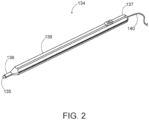
- FIG. 2 show an exemplary touch based registration and calibration instrument (134) that may be used to temporarily provide rigidity to an otherwise flimsy guidewire in order to register and calibrate an IGS navigation system such as IGS navigation system (100) described above.
- Calibration instrument (134) of this example comprises a rigid elongate body (138) having a distal end (136) and a proximal end (137).
- elongate body (138) is formed of a transparent polycarbonate material.
- Distal end (136) includes a taper leading to a reduced diameter portion, which ultimately terminates in a rounded distal tip (135).
- a guidewire (140) may be inserted into the rigid elongate body (138) so that an end of the guidewire (140) rests against the interior of the rounded distal tip (135). Since end of the guidewire (140) is positionally tracked, the rounded distal tip (135) may be used to touch a registration point on a patient's face, which will place the positionally tracked tip within close proximity of the registration point, separated only by the known width of a wall of the rigid elongate body (138).
- instrument (134) may be used to perform the registration and calibration process associated with IGS navigation system (100) by touching the rounded distal tip (135) to each registration point while providing another input to the system, such as interacting with a foot pedal or button, speaking a voice command, or another similar input, to cause the registration touch to be recorded.
- calibration instrument (134) includes a contact sensor (not shown) that senses when the distal tip (135) contacts the face of the patient. In some such versions, the operator must press distal tip (135) against the face of the patient with enough force to overcome a threshold for the contact sensor to register the contact between distal tip (135) and the face of the patient.
- distal tip (135) will be contacting registration points on the patient's head or face instead of the positionally tracked tip of the guidewire (140) contacting those registration points, the system may readily make the necessary adjustments in the registration and calibration algorithms in view of the fact that the width of the wall of the rigid elongate body (138) is fixed and known.
- the calibration instrument (134) or probe of FIG. 2 may provide rigidity to the flexible guidewire (140) during the registration process, which can address one source of inaccuracy (e.g., flexing of the positionally tracked guidewire during the touch). However, it does not address other sources of inaccuracy, for example, that introduced due to the flexibility or pliability of flesh on a patient's head or face as the distal tip (135) is pressed against it during the registration process. Various points on a patient's face may depress several millimeters under the force of the calibration instrument (134), which can provide a significant inaccuracy in the context of a ENT or other surgical procedure.
- one source of inaccuracy e.g., flexing of the positionally tracked guidewire during the touch.
- other sources of inaccuracy for example, that introduced due to the flexibility or pliability of flesh on a patient's head or face as the distal tip (135) is pressed against it during the registration process.
- FIG. 3 shows a front elevation view of a patient showing a patient registration procedure using the calibration instrument (134).
- the view of FIG. 3 might be rendered on a display of the IGS system (100) during a procedure, and may show one or more registration points (142) that must be calibrated or registered using the calibration instrument (134).
- the registration points may, for example, be shown in one color before they are registered with a touch of the calibration instrument (134), and may change to a different color or otherwise indicate calibration after a touch of the calibration instrument (134).
- one or more lasers are used to project the registration points (142) on the face of the patient, such that the operator must engage the face of the patient with distal tip (135) at each point illuminated by the laser(s).
- calibration instrument (134) may be configured and operable in accordance with at least some of the teachings of U.S. Pub. No. 2017/0119473, entitled “System and Method for Navigation of Surgical Instruments,” published May 4, 2017 .
- this registration may require five touches of the calibration instrument (134) at different points of the patient's face to be completed.
- the number of registration points can be in the tens or even hundreds. In this context, it becomes apparent that it can be a very time-consuming process to identify, locate, and touch each required point.
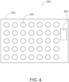
- FIGS. 4-6 show an exemplary sensor array (200) that may be used to perform patient registration instead of or in addition to a touch-based calibration instrument (134).
- the exemplary sensor array (200) comprises a case (202), a plurality of sensors (204), and a position sensor (206).
- the plurality of sensors (204) may comprise, for example, a set of optical sensors, ultrasonic sensors, or other proximity sensors that transmit a probe signal (e.g., a projected light, ultrasonic sound waves, electromagnetic waves, etc.) and then receive a corresponding response signal (e.g., a reflected light, reflected sound, reflected electromagnetic waves, etc.).
- a probe signal e.g., a projected light, ultrasonic sound waves, electromagnetic waves, etc.
- a response signal e.g., a reflected light, reflected sound, reflected electromagnetic waves, etc.
- the period of time between probe signal transmission and receipt of the response, or the strength or other characteristics of the response signal, may then be used to determine the distance between the sensor's signal transmitter and the target that the probe signal strikes.
- Other suitable forms that sensors (204) may take will be apparent to those of ordinary skill in the art in view of the teachings herein.
- Position sensor (206) may comprise one or more of an accelerometer, magnetic, or wireless beacon sensor that may be used to determine the location and orientation of sensor array (200) within three-dimensional space.
- An accelerometer based sensor may be able to determine movements and rotations of the sensor array (200) from a neutral point, which may be used to determine its real-time location at any time.
- Magnetic or other wireless sensors may operate in a manner similar to that described in relation to navigation guidewires, and may require a tracking element or receiving element located in the sensor array (200), and a tracking device or transmitting device located elsewhere in the procedure area and configured to identify the position of the tracking element at any time.
- Other suitable components that may be used to form position sensor (206) will be apparent to those of ordinary skill in the art in view of the teachings herein.
- patient registration may be used to identify the location of landmarks of a patient's face or other surgical site within three-dimensional space so that a set of preoperatively obtained images can be calibrated or otherwise synchronized with the real-world procedure setting.
- the location of sensor array (200) within three-dimensional space must be known, and the distance between sensor array (200) and the patient's face or other surgical site must be known.
- These variables can then be used to determine the location of landmarks or other positions on a patient's face or other surgical site within three-dimensional space.
- a laser beam may be produced by the source sensor (204), and the laser beam may strike a target across a distance of x-millimeters.
- a portion of the laser beam will be reflected off the target, with such reflected or scattered light being detected by source sensor (204).
- the period of time between laser projection and reflection detection may then be used to determine the x-millimeter distance that separates source sensor (204) and the target. If the position of source sensor (204) along the z-axis is "Z,” as determined by the position sensor (206), then the position of the target along the z-axis can be determined as (Z +/- x-millimeters).
- the plurality of sensors (204) are positioned at the same point along the z-axis (220) of the case (202). While this configuration may be adequate, it should also be understood that sensors (204) may be placed at different points along the z-axis (220) (e.g., to allow for differently shaped cases (202)), as the sensor's (204) initial position may be compensated for as long as it remains substantially static relative to the position sensor (206).
- the case (202) may be made of any substantially rigid material, such as plastics or metals, so that the front face of the case (202) on which the plurality of sensors (204) are placed will not flex under its own weight or during use. Such flex would result in a change of the sensors' (204) initial position along the z-axis (220) as reported by the position sensor (206), which may skew determination of the target's position within three dimensional.
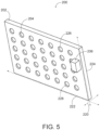
- the position sensor (206) may also determine its orientation within three-dimensional space. This may be useful where the sensor array (200) cannot be oriented so that its front face is completely parallel to the target surface. This could occur due to space limitations within a procedure area, to allow space for clinicians to access areas around the sensor array (200), human error, or other causes. Non-parallel orientation to the target may introduce inaccuracy if not accounted for, for the same reason that flexing of the case (202) along the z-axis might. For example, referring to FIG. 5 , and assuming that the target is completely parallel to the sensor array (200) as oriented in FIG.
- the position sensor's (206) orientation determining capability may detect that the sensor array (200) is not completely parallel to the target, and either warn an operator that sensor array (200) needs to be re-oriented.
- sensor array (200) (and/or some other system component) can adjust the data provided by each individual sensor (204) of the plurality of sensors (204) to account for the non-parallel orientation. This could include, for example, determining that, due to its orientation, the upper sensor (226) is x-millimeters closer to the target as compared to the lower sensor (228), and adjusting the calculations accordingly during calibration and registration.
- FIG. 8 shows an exemplary scenario where a sensor array (200) is not positioned and oriented so that it is substantially parallel to the target.
- the sensor array (200) is suspended from an arm (216) and is located above the target area (211), but is not oriented on the arm (216) so that it is substantially parallel to the target area (211), as can be seen by the intersecting lines (218, 220) drawn parallel to the sensor array (200) and the target area (211).
- the arm (216) may provide a wide range of manual or automatic motions to support a wide range of positions and orientations for an attached sensor array (200) relative to the target area (211).
- Some implementation may also include an orientation indicator that may comprise, for example, a lighted indicator, an audible indicator, or a haptic indicator configured to notify a user when the sensor array is substantially parallel to the target area (211) which may aid in manual positioning and orientation of the sensor array (200).
- an orientation indicator may comprise, for example, a lighted indicator, an audible indicator, or a haptic indicator configured to notify a user when the sensor array is substantially parallel to the target area (211) which may aid in manual positioning and orientation of the sensor array (200).
- the arm (216) may automatically adjust the position and orientation of the sensor array (200) relative to the target area (211) as it is activated or manually moved by a user, in order to maintain a substantially parallel orientation.
- FIG. 6 shows the sensor array (200) during activation with a simulated visualization of the area (208) that is within the sensing or detection range of the plurality of sensors (204).
- FIG. 7 shows a simulated visualization of a number of registration points on a patient's face that may be simultaneously detected and registered by the exemplary sensor array (200). As can be seen, a plurality of registration points (210) can be simultaneously registered by the large detection area (208) of the sensor array (200). Due to variations between the size of a patient's head and the sensor array (200), the probe signal transmitted by some of the sensors may miss the patient's head entirely (212).
- the response signal may not be received by the source sensor (e.g., where the distance to an incidental target is too great, or where the patient's head is laid against a surface that does not result in a response signal), or the response signal may be received and the calculated distance to the target determines that a point beyond the patient's face has been measured.
- data generated by the sensor that is not striking the patient's face may be filtered or otherwise disregarded for registration purposes, while valid registration points (210) may be registered in order to locate the patient's facial landmarks in three-dimensional space.
- the exemplary sensor array (200) may provide several advantages as compared to a touch calibration instrument (134). As can be seen in FIGS. 6-7 , the sensor array (200) can register a plurality of points (210) simultaneously, and can be scaled to any desired number or affected area by varying the size of the sensor array (200) and/or the number and arrangement of the plurality of sensors (204). In comparison to the potentially time consuming point-by-point registration offered by a touch calibration instrument (134), a sensor array (200) may complete registration by simply positioning and orienting it be substantially parallel to the target (e.g., by moving an arm, gimble, or other apparatus such as the arm (216) shown in FIG.
- FIGS. 10-11 show methods for touchless facial registration of an image guided surgical system that may be performed by a system such as that shown in FIG. 9 .
- the exemplary system of FIG. 9 comprises an image guided surgery or IGS system (300), an image server (302), a procedure area positioning system (306), and a registration sensor (304).
- IGS system image guided surgery or IGS system
- image server 302
- procedure area positioning system 306
- registration sensor 304
- the components of the exemplary system, and their function as described are example only and could be implemented in a variety of ways. For example, some features could be performed by either the IGS system (300), the registration sensor (304), or both, in some implementations. Similarly, some components may be combined or divided into further components.
- IGS system (300) functions performed by the IGS system (300) may be performed across several components (e.g., an IGS system (300), a cloud computing system, a handheld IGS device, or others), or the functions of the IGS system (300) and image server (302) could be combined and performed by a single component or device.
- IGS system (300) may be performed across several components (e.g., an IGS system (300), a cloud computing system, a handheld IGS device, or others), or the functions of the IGS system (300) and image server (302) could be combined and performed by a single component or device.
- image server (302) could be combined and performed by a single component or device.
- the IGS system (300) may comprise a computer having components such as a processor and memory, storage, display, and various user and communication interfaces.
- the IGS system (300) may be configured to receive information from one or more of the area positioning system (306), the registration sensor (304), the image server (302), and/or other data sources.
- Information received by the IGS system may be used to prepare and display or otherwise provide information such as images, sounds, video, and software tools to assist in the performance of a surgical procedure.
- Received information may comprise, for example, pre-operational images, video, and data from the image server (302) or another system, facial landmark registration from a registration sensor (304), procedure area positioning and orientation data for tools and other objects within the procedure area from the area positioning system (306), and other similar data.
- the IGS system (300) may, for example, track a number of positionally tracked devices within three-dimensional space, and map a registered patient within that three-dimensional space so that pre-operative images may be accurately associated with images generated during a procedure.
- the image server (302) may be one or more remotely or locally located servers that may store pre-procedure information, procedure information, and post procedure information, which may include pre-operative images, locations and orientations of instruments, devices, and other tracked objects during a procedure, and post-procedure analysis or other metrics that may aid in the assessment of the performance of a procedure.
- the registration sensor (304) may comprise, for example, a sensor array (200), or another registration instrument such as the exemplary sensor probe (500) of FIG. 12 .
- the registration sensor (304) is configured to provide some or all of the information required to locate the target area (211) (e.g., a patient's facial landmarks) within three-dimensional space, as has been described in relation to the sensor array (200). This could include, for example, determining the distance between a source sensor (204) and a target.
- the area positioning system (306) which may be, for example, a tri-axis sensor as described in relation the position sensor (206), may provide any additional information that is needed to locate the target area (211) within three-dimensional space, which could include, for example, determining the position of the source sensor (204).
- the components of the system of FIG. 9 may be in communication with the IGS system (300) and, in some implementations, with each other, via various forms of wired and wireless communication.
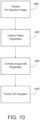
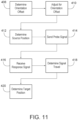
- FIG. 11 shows a set of high level steps that may be performed using the system of FIG. 9 in order to register a patient in three-dimensional space using a registration sensor (304), which will allow for IGS navigation features to be provided at the IGS system (300).
- the exemplary steps comprise receiving pre-operative images (block 400), receiving patient registration (block 402), correlating the pre-operative images with the patient registration (block 404), and providing IGS navigation (block 406).
- Receiving pre-operative images may comprise, for example, requesting and/or receiving one or more data sets from an image server (302), local storage, or another similar device. Received information may then be stored locally to the IGS system (300) and kept readily available so that it may be quickly accessed during IGS navigation.
- Performing the patient registration may comprise activating a registration sensor (304) in order to produce a set of data indicating the distance between the registration sensor (304) and the target area (211), in the form of one or more registration points that can be used to locate landmarks or other physical features of a patient's face or other target area (211) features, and may also include using an area positioning system (306) to determine the location of the registration sensor (304), so that the patient's face can be located within three dimensional space relative to the area positioning system (306).
- Correlating pre-operative images with the registration data may comprise selecting one or more of the pre-operative images and mapping them within three-dimensional space relative to the target area (211).
- Providing IGS navigation may then be performed by using an accurate three-dimensional mapping of the pre-operative images relative to the target area (211). This allows for the IGS system (300) to accurately display the positions of presently tracked objects (e.g., guidewires or other positionally tracked instruments) in the context of the pre-operative images during a procedure where IGS navigation is used.
- presently tracked objects e.g., guidewires or other positionally tracked instruments
- FIG. 11 shows an exemplary set of steps that may be performed when performing a patient registration (block 402) with a registration sensor (304). These steps may be performed by the IGS system (300), the registration sensor (304), and/or another device having appropriate processing, memory, and storage capabilities, and may be performed in varying orders or in parallel in some implementations, unless the nature of a particular step which requires, as input, data that becomes available only upon completion of a prior step.
- the IGS system (300) may determine an orientation offset (block 408) based upon orientation data associated with the registration sensor (304) and the target area (211) in order to determine whether they are substantially parallel.
- the IGS system (300) may adjust one or more variables to account for this offset (block 410). This could include, for example, increasing or reducing the measured distance between a source sensor and a target to account for a non-parallel orientation, as has been previously described.
- the IGS system (300) may also determine a source position (block 412) for the registration sensor (304). As with determining orientation, this may include determining a current position using information from a position sensor (206, 506) or other area positioning system (306), or using a pre-determined static value where it is possible for a registration sensor (304) to be statically fixed in position.
- the IGS system (300) may also send a probe signal (block 414) by activating one or more sensors of a registration sensor (304), and receive a response signal (block 416) that is reflected, echoed, or otherwise returned from the target area (211) and captured by a photo eye, microphone, or other receiver.
- the IGS system (300) may determine the signal travel time and distance (block 418). When determining signal travel distance (block 418), the IGS system may account for any orientation offset for particular sensors that may have been earlier determined (block 410).
- signal travel distance (block 418) and signal source position (block 412) have been determined and are available to IGS system (300), the system may determine (block 420) and store the target area (211) position. Once the target position is known (block 420), the IGS system may use that position to correlate pre-operative images (block 404) with the target area (211) and provide IGS navigation (block 406).
- FIGS. 12-13 show an exemplary alternative sensor probe that may be used to, in a manner similar to previously discussed touch probes such as the calibration instrument (134), register a patient one point at a time.
- the probe (500) shown in FIG. 12 comprises a probe transmitter (502), a probe receiver (504), a position sensor (506), and a proximity trigger (508). While probe transmitter (502) and probe receiver (504) are shown as separate components, probe transmitter (502) and probe receiver (504) may in fact be integrated into a single component in some variations.
- the probe (500) could be implemented in a variety of forms, for example, a housing similar to the elongate body (138) of the calibration instrument (134) could contain or be attached to one or more of the components of FIG. 12 .
- a housing or body such as that of the calibration instrument (134) may be a desirable form for the probe (500) because the stylus-like shape may be comfortable and familiar to users (e.g., grasping probe (500) with a pencil grip).
- the probe (500) When registering a point on a target area (211), the probe (500) operates in a manner similar to the sensor array (200).
- the probe transmitter (502) and probe receiver (504) may be positioned towards the tip end of the probe (e.g., at the rounded distal tip if the probe (500) were implemented in a form similar to that of FIG. 2 ), and, when activated, function similarly to a sensor (204) of the sensor array (200) as described above.
- the probe transmitter (502) which could comprise an optical transmitter, ultrasound transmitter, or other wireless transmitter, will transmit a probe signal (512) towards the target area (211), as shown in FIG. 13 .
- the probe signal will reflect, echo, or otherwise return from the target area (211) and be received by the probe receiver (504) as a response signal (514).
- the time of travel between the probe signal transmission and receipt of the response signal can be used by an IGS system (300) or another processing device to determine the distance between the probe (500) and the target area (211). This distance, combined with a position and orientation of the probe (500) as supplied by a position sensor (506) may then be used to determine the registered point of the target area (211) in three-dimensional space.
- the position sensor (506) may comprise a tri-axis sensor, accelerometer based positioning sensor, magnetic positioning sensor, or other positioning sensor that may function as or function with the area positioning system (306) in order to provide a position and orientation of the probe (500).
- the proximity trigger (508) of the probe (500) may itself comprise a sensor, or may be a feature or configuration of the probe transmitter (502) and probe receiver (504) that is configured to determine real-time proximity relative to the target area (211) and, when it is within a certain proximity of a target, capture and register a point of the target area (211). This allows for the probe (500) to automatically activate and register points when positioned proximately to the target area (211), so as to avoid the need for a user clicking a button, foot pedal, or making contact with the target area (211) with force above a certain threshold in order to capture the registration point data.
- the user may move probe (500) about the target area (211) within a proximity that causes the proximity trigger (508) to register points of the target area (211) in order to complete the registration process.
- this would allow the probe (500) to rapidly register a number of points across the target area (211) without substantially pressing against any point of the target area (211) or taking other actions to trigger the registration that may reduce the accuracy of the registration.
- probe (500) comprises a capacitive sensor or a resistive sensor, either of which may be used to effectively form (or serve as a substitute for) the combination of probe transmitter (502) and probe receiver (504).
- the capacitive sensor or resistive sensor may be able to detect contact with a patient's face and thereby register the position, with a relatively light touch on the patient's face.
- an operator need not press probe (500) against the patient's face with substantial force in order to activate a capacitive sensor or a resistive sensor through contact with the patient's face.
- probe (500) may be used in conjunction with one or more lasers that are used to project the registration points (142) on the face of the patient, such that the operator must use probe (500) to register the locations of each point illuminated by the laser(s) on the patient's face. While use of the probe (500) may be slower than the sensor array (200), it may also be much faster than the use of a probe such as the calibration instrument (134).
- the probe (500) may provide additional beneficial features, such as ease of use, reduced complexity (e.g., one sensor rather than an array of sensors), reduced power consumption, increased mobility (e.g., handheld rather than arm or ceiling mounted), reduced cost, and other similar benefits that will be apparent to one of ordinary skill in light of this disclosure.
- registration sensors may be implemented in a variety of forms beyond those of a sensor array (200) or a probe (500). This could include, for example, a single row of sensors disposed along a longitudinal member that can be passed across a target area, one or more rows of sensors disposed along a curved member that can be rotated around a target area, or other similar configurations.
- sensors e.g., optical sensors, ultrasonic sensors, proximity sensors, capacitive sensors, resistive sensors, etc.
- sensor array (200) and probe (500) are known in industrial/manufacturing settings (e.g., tracking objects in an assembly line, etc.)
- industrial/manufacturing settings e.g., tracking objects in an assembly line, etc.
- tracked objects may be more likely to have consistent surface geometry (e.g., the sensed surface is flat), consistent surface coloring, and/or other consistent properties.
- the sensors may experience a substantially greater range in variation among the sensed surfaces.
- Such variations may include various surface contours, colors, lividity, and/or other variations in properties of human faces.
- the sensors and/or the manner in which the sensors are operated may be modified to accommodate such variation among the sensed surfaces.
- optical sensors may be configured to operate on different light frequencies (e.g., sweeping through a plurality of frequencies) to more readily account for variation in skin tone among various patients.
- Other ways in which sensors and/or the manner in which the sensors are operated may be modified to account for variation among human face properties will be apparent to those of ordinary skill in the art in view of the teachings herein.
- Versions of the devices disclosed herein can be designed to be disposed of after a single use, or they can be designed to be used multiple times. Versions may, in either or both cases, be reconditioned for reuse after at least one use. Reconditioning may include any combination of the steps of disassembly of the device, followed by cleaning or 26 replacement of particular pieces, and subsequent reassembly. In particular, versions of the device may be disassembled, and any number of the particular pieces or parts of the device may be selectively replaced or removed in any combination. Upon cleaning and/or replacement of particular parts, versions of the device may be reassembled for subsequent use either at a reconditioning facility, or by a surgical team immediately prior to a surgical procedure.
- reconditioning of a device may utilize a variety of techniques for disassembly, cleaning/replacement, and reassembly. Use of such techniques, and the resulting reconditioned device, are all within the scope of the present application.
- versions described herein may be processed before surgery.
- a new or used instrument may be obtained and if necessary cleaned.
- the instrument may then be sterilized.
- the instrument is placed in a closed and sealed container, such as a plastic or TYVEK bag.
- the container and instrument may then be placed in a field of radiation that can penetrate the container, such as gamma radiation, x-rays, or high-energy electrons.
- the radiation may kill bacteria on the instrument and in the container.
- the sterilized instrument may then be stored in the sterile container.
- the sealed container may keep the instrument sterile until it is opened in a surgical facility.
- a device may also be sterilized using any other technique known in the art, including but not limited to beta or gamma radiation, ethylene oxide, or steam.
Landscapes
- Health & Medical Sciences (AREA)
- Life Sciences & Earth Sciences (AREA)
- Surgery (AREA)
- Engineering & Computer Science (AREA)
- Molecular Biology (AREA)
- Public Health (AREA)
- Veterinary Medicine (AREA)
- General Health & Medical Sciences (AREA)
- Animal Behavior & Ethology (AREA)
- Biomedical Technology (AREA)
- Heart & Thoracic Surgery (AREA)
- Medical Informatics (AREA)
- Nuclear Medicine, Radiotherapy & Molecular Imaging (AREA)
- Oral & Maxillofacial Surgery (AREA)
- Pathology (AREA)
- Physics & Mathematics (AREA)
- Otolaryngology (AREA)
- Dentistry (AREA)
- Pulmonology (AREA)
- Robotics (AREA)
- Optics & Photonics (AREA)
- Human Computer Interaction (AREA)
- Biophysics (AREA)
- Surgical Instruments (AREA)
- Image Analysis (AREA)
- Control Of Position, Course, Altitude, Or Attitude Of Moving Bodies (AREA)
- Apparatus For Radiation Diagnosis (AREA)
Claims (14)
- System (300) zur Registrierung einer Zielfläche durch Erfassung und Registrierung einer Vielzahl von Registrierungspunkten der Zielfläche, wobei das System umfasst:(a) einen Sensoranordnungskörper (202),(b) eine Vielzahl von Abstandssensoren (204, 226, 228), die an dem Sensoranordnungskörper angebracht sind, wobei jeder der Abstandssensoren positioniert ist, um auf die Zielfläche gerichtet zu sein, und bedienbar ist, um einen Abstand zwischen einem Registrierungspunkt der Zielfläche und dem Sensor zu bestimmen,(c) einen Positionssensor (206), der an dem Sensoranordnungskörper angebracht und bedienbar ist, um eine Position und eine Ausrichtung des Sensoranordnungskörpers bereitzustellen, und(d) mindestens einen Prozessor, wobei der mindestens eine Prozessor dazu ausgelegt ist, den dreidimensionalen Ort einer Vielzahl von registrierten Punkten der Zielfläche in einem Verfahrensraum basierend auf dem Abstand, der Ausrichtung und der Position für jeden der Abstandssensoren zu bestimmen.
- System nach Anspruch 1, wobei die Abstandssensoren in einer Form angeordnet sind, die aus der Gruppe bestehend aus einem Rechteck, einem Quadrat, einem Kreis, einem Dreieck und einer Ellipse ausgewählt ist.
- System nach Anspruch 1, wobei eine Fläche des Sensoranordnungskörpers im Wesentlichen flach ist, und wobei der mindestens eine Prozessor in dem Sensoranordnungskörper enthalten ist.
- System nach Anspruch 1, wobei die Abstandssensoren einen Typ ausgewählt aus der Gruppe bestehend aus einem optischen Sensor, einem Ultraschallsensor und einem Magnetsensor umfassen.
- System nach Anspruch 1, wobei der mindestens eine Prozessor dazu ausgelegt ist, den dreidimensionalen Ort der Vielzahl von registrierten Punkten für jeden Sensor der Vielzahl von Abstandssensoren zu bestimmen durch:(i) Bestimmen einer ursprünglichen Position für ein von dem Sensor gesendetes Sondensignal, wobei die ursprüngliche Position die Position dieses Sensors in dem Verfahrensraum anzeigt, basierend auf der Position und der Ausrichtung des Sensoranordnungskörpers, und(ii) Bestimmen eines registrierten Punktes für diesen Sensor basierend auf der ursprünglichen Position und einem Abstand, der von dem Sondensignal zurückgelegt wurde, bevor es auf den Registrierungspunkt der Zielfläche trifft.
- System nach Anspruch 5, wobei der mindestens eine Prozessor ferner dazu ausgelegt ist:(i) eine Ausrichtung der Zielfläche bezogen auf den Sensoranordnungskörper zu bestimmen,(ii) dort, wo die Zielfläche und der Sensoranordnungskörper im Wesentlichen nicht parallel sind, für jeden Sensor der Vielzahl von Abstandssensoren einen Versatzwert zu bestimmen, und(iii) den registrierten Punkt für diesen Sensor basierend auf der ursprünglichen Position, dem von dem Sondensignal zurückgelegten Abstand und dem Versatzwert zu bestimmen.
- System nach Anspruch 6, ferner umfassend einen Zielflächenausrichtungssensor, der dazu ausgelegt ist, dem mindestens einen Prozessor eine Ausrichtung der Zielfläche bereitzustellen.
- System nach Anspruch 1, wobei ein Navigationsprozessor des mindestens einen Prozessors dazu ausgelegt ist:(i) die Vielzahl von registrierten Punkten mit einem Satz von präoperativen Bildern der Zielfläche zu verknüpfen, und(ii) eine bildgeführte Eingriffnavigationsschnittstelle während eines Verfahrens basierend auf der Verknüpfung der Vielzahl von registrierten Punkten, dem Satz von präoperativen Bildern und einem Satz von Instrumentendaten, die von einem Positionssensor eines während des Verfahrens verwendeten chirurgischen Instruments bereitgestellt wurden, bereitzustellen.
- System nach Anspruch 1, wobei die Abstandssensoren dazu ausgelegt sind, in einem Abstand von zwischen ungefähr 4 Zoll und 20 Zoll von dem Zielort positioniert und betrieben zu werden, wenn der Standort der Vielzahl von registrierten Punkten bestimmt ist.
- System nach Anspruch 1, ferner umfassend eine Ausrichtungsanzeige, wobei die Ausrichtungsanzeige dazu ausgelegt ist, einem Benutzer eine Anzeige bereitzustellen, wenn der Sensoranordnungskörper nicht im Wesentlichen parallel zu der Zielfläche ist.
- System nach Anspruch 1, ferner umfassend einen automatisierten Arm (216), wobei der automatisierte Arm betrieben werden kann, um den Sensoranordnungskörper derart auszurichten, dass er im Wesentlichen parallel zu der Zielfläche ist.
- System nach Anspruch 1, wobei die Vielzahl von Abstandssensoren mindestens 30 Einzelsensoren umfasst, und wobei die Vielzahl von Abstandssensoren derart an dem Sensoranordnungskörper positioniert sind, dass die gesendeten Sondensignale im Wesentlichen alle Zielflächen treffen.
- System nach Anspruch 1, wobei der mindestens eine Prozessor ferner dazu ausgelegt ist, bei jedem beliebigen Sensor der Vielzahl von Abstandssensoren, dessen Sondensignal während der Verwendung außerhalb der Zielfläche liegt, die Näherungsdaten von diesem Sensor zu ignorieren.
- System nach Anspruch 1, wobei die Vielzahl von Abstandssensoren dazu ausgelegt ist, einmal aktiviert zu werden, um die Daten zu erfassen, die verwendet werden, um den dreidimensionalen Ort der Vielzahl von registrierten Punkten zu bestimmen.
Priority Applications (1)
| Application Number | Priority Date | Filing Date | Title |
|---|---|---|---|
| EP23217763.4A EP4316400A3 (de) | 2017-12-22 | 2018-12-19 | Vorrichtung und verfahren zur registrierung von gesichtsmarkierungen für ein chirurgisches navigationssystem |
Applications Claiming Priority (2)
| Application Number | Priority Date | Filing Date | Title |
|---|---|---|---|
| US15/852,169 US10786311B2 (en) | 2017-12-22 | 2017-12-22 | Apparatus and method for registering facial landmarks for surgical navigation system |
| PCT/IB2018/060350 WO2019123321A1 (en) | 2017-12-22 | 2018-12-19 | Apparatus and method for registering facial landmarks for surgical navigation system |
Related Child Applications (1)
| Application Number | Title | Priority Date | Filing Date |
|---|---|---|---|
| EP23217763.4A Division EP4316400A3 (de) | 2017-12-22 | 2018-12-19 | Vorrichtung und verfahren zur registrierung von gesichtsmarkierungen für ein chirurgisches navigationssystem |
Publications (3)
| Publication Number | Publication Date |
|---|---|
| EP3727147A1 EP3727147A1 (de) | 2020-10-28 |
| EP3727147C0 EP3727147C0 (de) | 2023-12-27 |
| EP3727147B1 true EP3727147B1 (de) | 2023-12-27 |
Family
ID=65324411
Family Applications (2)
| Application Number | Title | Priority Date | Filing Date |
|---|---|---|---|
| EP18845358.3A Active EP3727147B1 (de) | 2017-12-22 | 2018-12-19 | Vorrichtung und verfahren zur registrierung von gesichtsmarkierungen für ein chirurgisches navigationssystem |
| EP23217763.4A Pending EP4316400A3 (de) | 2017-12-22 | 2018-12-19 | Vorrichtung und verfahren zur registrierung von gesichtsmarkierungen für ein chirurgisches navigationssystem |
Family Applications After (1)
| Application Number | Title | Priority Date | Filing Date |
|---|---|---|---|
| EP23217763.4A Pending EP4316400A3 (de) | 2017-12-22 | 2018-12-19 | Vorrichtung und verfahren zur registrierung von gesichtsmarkierungen für ein chirurgisches navigationssystem |
Country Status (6)
| Country | Link |
|---|---|
| US (2) | US10786311B2 (de) |
| EP (2) | EP3727147B1 (de) |
| JP (1) | JP7271551B2 (de) |
| CN (1) | CN111511281B (de) |
| IL (1) | IL275021B2 (de) |
| WO (1) | WO2019123321A1 (de) |
Families Citing this family (13)
| Publication number | Priority date | Publication date | Assignee | Title |
|---|---|---|---|---|
| US10322269B1 (en) | 2015-01-19 | 2019-06-18 | Dalent, LLC | Dilator device |
| US10786311B2 (en) | 2017-12-22 | 2020-09-29 | Acclarent, Inc. | Apparatus and method for registering facial landmarks for surgical navigation system |
| US11481909B2 (en) * | 2018-12-06 | 2022-10-25 | Biosense Webster (Israel) Ltd. | Method and apparatus for performing facial registration |
| US11744646B2 (en) | 2018-12-12 | 2023-09-05 | Acclarent, Inc. | Registration probe for image guided surgery system |
| US12458784B2 (en) | 2019-06-11 | 2025-11-04 | Dalent, LLC | Balloon dilation device |
| US11571260B2 (en) * | 2020-03-31 | 2023-02-07 | Biosense Webster (Israel) Ltd. | Pre-operative registration of anatomical images with a position-tracking system using ultrasound measurement of skin tissue |
| CN113133828B (zh) * | 2021-04-01 | 2023-12-01 | 上海复拓知达医疗科技有限公司 | 一种用于手术导航的交互配准系统、方法、电子设备和可读存储介质 |
| US20220370143A1 (en) | 2021-05-20 | 2022-11-24 | Acclarent, Inc. | Registration probe for enhanced information capture |
| CN114767269A (zh) * | 2022-04-13 | 2022-07-22 | 苏州迪凯尔医疗科技有限公司 | 用于口腔种植手术的配准系统及方法 |
| CN116725679B (zh) * | 2022-08-12 | 2024-07-12 | 北京和华瑞博医疗科技有限公司 | 配准点确定以及配准方法、装置、设备、介质和程序产品 |
| US12413843B2 (en) * | 2023-04-07 | 2025-09-09 | Medtronic Navigation, Inc. | System and method of patient registration |
| WO2024231740A1 (en) * | 2023-05-05 | 2024-11-14 | Biosense Webster (Israel) Ltd. | Medical instrument navigation system registration probe with depth-finding or imaging capabilities |
| KR20250062065A (ko) * | 2023-10-30 | 2025-05-08 | 주식회사 제이시스메디칼 | 피부 모니터링 장치, 피부 관리 장치 및 피부 모니터링 기반의 피부 관리 시스템 |
Family Cites Families (39)
| Publication number | Priority date | Publication date | Assignee | Title |
|---|---|---|---|---|
| CA2246288C (en) * | 1996-02-15 | 2005-09-20 | Biosense, Inc. | Medical probes with field transducers |
| US6096050A (en) * | 1997-09-19 | 2000-08-01 | Surgical Navigation Specialist Inc. | Method and apparatus for correlating a body with an image of the body |
| US20020193685A1 (en) | 2001-06-08 | 2002-12-19 | Calypso Medical, Inc. | Guided Radiation Therapy System |
| US7831292B2 (en) * | 2002-03-06 | 2010-11-09 | Mako Surgical Corp. | Guidance system and method for surgical procedures with improved feedback |
| DE10241069B4 (de) * | 2002-09-05 | 2004-07-15 | Aesculap Ag & Co. Kg | Vorrichtung zur Erfassung der Kontur einer Oberfläche |
| US7974681B2 (en) * | 2004-03-05 | 2011-07-05 | Hansen Medical, Inc. | Robotic catheter system |
| EP1574825A1 (de) * | 2004-03-12 | 2005-09-14 | Xitact S.A. | vorrichtung zur bestimmung der longitudianl- und winkelstellung eines rotationssymmetrischen bauteils |
| US7720521B2 (en) | 2004-04-21 | 2010-05-18 | Acclarent, Inc. | Methods and devices for performing procedures within the ear, nose, throat and paranasal sinuses |
| US20110004057A1 (en) | 2004-04-21 | 2011-01-06 | Acclarent, Inc. | Systems and methods for transnasal dilation of passageways in the ear, nose or throat |
| US7654997B2 (en) * | 2004-04-21 | 2010-02-02 | Acclarent, Inc. | Devices, systems and methods for diagnosing and treating sinusitus and other disorders of the ears, nose and/or throat |
| US8702626B1 (en) | 2004-04-21 | 2014-04-22 | Acclarent, Inc. | Guidewires for performing image guided procedures |
| US20070208252A1 (en) | 2004-04-21 | 2007-09-06 | Acclarent, Inc. | Systems and methods for performing image guided procedures within the ear, nose, throat and paranasal sinuses |
| US20070126716A1 (en) | 2005-11-17 | 2007-06-07 | Jonathan Haverly | Digital pen |
| AT502919B1 (de) * | 2005-12-14 | 2010-11-15 | Univ Innsbruck | Medizinisches navigationssystem |
| US20070167741A1 (en) * | 2005-12-30 | 2007-07-19 | Sherman Jason T | Apparatus and method for registering a bone of a patient with a computer assisted orthopaedic surgery system |
| US7525309B2 (en) * | 2005-12-30 | 2009-04-28 | Depuy Products, Inc. | Magnetic sensor array |
| US20070161888A1 (en) * | 2005-12-30 | 2007-07-12 | Sherman Jason T | System and method for registering a bone of a patient with a computer assisted orthopaedic surgery system |
| US8862200B2 (en) * | 2005-12-30 | 2014-10-14 | DePuy Synthes Products, LLC | Method for determining a position of a magnetic source |
| US8040127B2 (en) | 2006-08-15 | 2011-10-18 | General Electric Company | Multi-sensor distortion mapping method and system |
| FR2917598B1 (fr) * | 2007-06-19 | 2010-04-02 | Medtech | Plateforme robotisee multi-applicative pour la neurochirurgie et procede de recalage |
| DE102007046186A1 (de) * | 2007-09-26 | 2009-04-02 | Amedo Smart Tracking Solutions Gmbh | Gewebemarkierung |
| US8320711B2 (en) | 2007-12-05 | 2012-11-27 | Biosense Webster, Inc. | Anatomical modeling from a 3-D image and a surface mapping |
| JP5213200B2 (ja) * | 2008-02-27 | 2013-06-19 | 国立大学法人浜松医科大学 | 手術支援システム用体内挿入器具 |
| US9285246B2 (en) * | 2010-02-12 | 2016-03-15 | Intuitive Surgical Operations, Inc. | Method and system for absolute three-dimensional measurements using a twist-insensitive shape sensor |
| CN101797182A (zh) * | 2010-05-20 | 2010-08-11 | 北京理工大学 | 一种基于增强现实技术的鼻内镜微创手术导航系统 |
| WO2011159621A2 (en) * | 2010-06-13 | 2011-12-22 | Angiometrix Corporation | Methods and systems for determining vascular bodily lumen information and guiding medical devices |
| US8794830B2 (en) * | 2010-10-13 | 2014-08-05 | Biosense Webster, Inc. | Catheter with digitized temperature measurement in control handle |
| US8900131B2 (en) * | 2011-05-13 | 2014-12-02 | Intuitive Surgical Operations, Inc. | Medical system providing dynamic registration of a model of an anatomical structure for image-guided surgery |
| US9188973B2 (en) * | 2011-07-08 | 2015-11-17 | Restoration Robotics, Inc. | Calibration and transformation of a camera system's coordinate system |
| US10779751B2 (en) * | 2013-01-25 | 2020-09-22 | Medtronic Navigation, Inc. | System and process of utilizing image data to place a member |
| EP2769689B8 (de) * | 2013-02-25 | 2018-06-27 | Stryker European Holdings I, LLC | Computerimplementierte Technik zur Berechnung einer Position einer chirurgischen Vorrichtung |
| US9285666B2 (en) * | 2014-04-16 | 2016-03-15 | Eue Medical Technology Co., Ltd. | Object guide system |
| US10463242B2 (en) | 2014-07-09 | 2019-11-05 | Acclarent, Inc. | Guidewire navigation for sinuplasty |
| US10226193B2 (en) * | 2015-03-31 | 2019-03-12 | Medtronic Ps Medical, Inc. | Wireless pressure measurement and monitoring for shunts |
| US10362965B2 (en) | 2015-04-22 | 2019-07-30 | Acclarent, Inc. | System and method to map structures of nasal cavity |
| JP6141559B1 (ja) * | 2015-07-06 | 2017-06-07 | オリンパス株式会社 | 医療装置、医療画像生成方法及び医療画像生成プログラム |
| US10779891B2 (en) | 2015-10-30 | 2020-09-22 | Acclarent, Inc. | System and method for navigation of surgical instruments |
| US10327853B2 (en) * | 2016-05-10 | 2019-06-25 | Covidien Lp | System and method of performing treatment along a lumen network |
| US10786311B2 (en) | 2017-12-22 | 2020-09-29 | Acclarent, Inc. | Apparatus and method for registering facial landmarks for surgical navigation system |
-
2017
- 2017-12-22 US US15/852,169 patent/US10786311B2/en active Active
-
2018
- 2018-12-19 JP JP2020534483A patent/JP7271551B2/ja active Active
- 2018-12-19 CN CN201880083077.6A patent/CN111511281B/zh active Active
- 2018-12-19 WO PCT/IB2018/060350 patent/WO2019123321A1/en not_active Ceased
- 2018-12-19 EP EP18845358.3A patent/EP3727147B1/de active Active
- 2018-12-19 EP EP23217763.4A patent/EP4316400A3/de active Pending
-
2020
- 2020-05-31 IL IL275021A patent/IL275021B2/en unknown
- 2020-09-10 US US17/016,453 patent/US11419685B2/en active Active
Also Published As
| Publication number | Publication date |
|---|---|
| US20190192228A1 (en) | 2019-06-27 |
| JP2021507763A (ja) | 2021-02-25 |
| EP4316400A3 (de) | 2024-05-08 |
| JP7271551B2 (ja) | 2023-05-11 |
| US11419685B2 (en) | 2022-08-23 |
| EP4316400A2 (de) | 2024-02-07 |
| US20210106390A1 (en) | 2021-04-15 |
| CN111511281B (zh) | 2024-04-26 |
| EP3727147A1 (de) | 2020-10-28 |
| EP3727147C0 (de) | 2023-12-27 |
| WO2019123321A1 (en) | 2019-06-27 |
| IL275021A (en) | 2020-07-30 |
| CN111511281A (zh) | 2020-08-07 |
| US10786311B2 (en) | 2020-09-29 |
| IL275021B2 (en) | 2023-06-01 |
Similar Documents
| Publication | Publication Date | Title |
|---|---|---|
| US11419685B2 (en) | Apparatus and method for registering facial landmarks for surgical navigation system | |
| EP2769689B1 (de) | Computerimplementierte Technik zur Berechnung einer Position einer chirurgischen Vorrichtung | |
| JP5662638B2 (ja) | 副鼻洞形成術ナビゲーションのためのフルオロスコープと計算機式断層写真法との位置揃えのシステム及び利用方法 | |
| EP3515288B1 (de) | Visualisierung eines bildobjekts im zusammenhang mit einem instrument in einem extrakorporalen bild | |
| JP2014510608A (ja) | 心臓置換弁の超音波誘導による位置決め | |
| EP2233099A2 (de) | Rechnerunterstütztes System zum Führen eines chirurgischen Instruments während perkutaner Diagnostik oder therapeutischer Operationen | |
| US10314658B2 (en) | Registration of an anatomical image with a position-tracking coordinate system based on visual proximity to bone tissue | |
| US20230143522A1 (en) | Surgical assistant system based on image data of the operative field | |
| US12207889B2 (en) | Endoscope with procedure guidance | |
| JP7483468B2 (ja) | 医療器具の識別 | |
| CN118804723A (zh) | 用于图像引导外科手术的定制患者跟踪器 | |
| JP2019088784A (ja) | 耳鼻咽喉科用剛性ツールの較正 | |
| US11571260B2 (en) | Pre-operative registration of anatomical images with a position-tracking system using ultrasound measurement of skin tissue | |
| US20230233097A1 (en) | Customized patient tracker for image guided surgery | |
| US20240366180A1 (en) | Medical instrument navigation system registration probe with depth-finding or imaging capabilites | |
| EP4460258A1 (de) | Kundenspezifischer patientenverfolger für bildgeführte chirurgie | |
| US20240415581A1 (en) | Method for providing a curvature parameter, medical object and system | |
| US20240350204A1 (en) | Apparatus and method to overlay information on endoscopic images | |
| JP2011056070A (ja) | 手術ナビゲーションシステム及びこれに用いる磁気センサ装着具 | |
| WO2024231740A1 (en) | Medical instrument navigation system registration probe with depth-finding or imaging capabilities | |
| RU2781623C2 (ru) | Система предупреждения дебридера |
Legal Events
| Date | Code | Title | Description |
|---|---|---|---|
| STAA | Information on the status of an ep patent application or granted ep patent |
Free format text: STATUS: UNKNOWN |
|
| STAA | Information on the status of an ep patent application or granted ep patent |
Free format text: STATUS: THE INTERNATIONAL PUBLICATION HAS BEEN MADE |
|
| PUAI | Public reference made under article 153(3) epc to a published international application that has entered the european phase |
Free format text: ORIGINAL CODE: 0009012 |
|
| STAA | Information on the status of an ep patent application or granted ep patent |
Free format text: STATUS: REQUEST FOR EXAMINATION WAS MADE |
|
| 17P | Request for examination filed |
Effective date: 20200518 |
|
| AK | Designated contracting states |
Kind code of ref document: A1 Designated state(s): AL AT BE BG CH CY CZ DE DK EE ES FI FR GB GR HR HU IE IS IT LI LT LU LV MC MK MT NL NO PL PT RO RS SE SI SK SM TR |
|
| AX | Request for extension of the european patent |
Extension state: BA ME |
|
| DAV | Request for validation of the european patent (deleted) | ||
| DAX | Request for extension of the european patent (deleted) | ||
| GRAP | Despatch of communication of intention to grant a patent |
Free format text: ORIGINAL CODE: EPIDOSNIGR1 |
|
| STAA | Information on the status of an ep patent application or granted ep patent |
Free format text: STATUS: GRANT OF PATENT IS INTENDED |
|
| INTG | Intention to grant announced |
Effective date: 20230125 |
|
| GRAJ | Information related to disapproval of communication of intention to grant by the applicant or resumption of examination proceedings by the epo deleted |
Free format text: ORIGINAL CODE: EPIDOSDIGR1 |
|
| STAA | Information on the status of an ep patent application or granted ep patent |
Free format text: STATUS: REQUEST FOR EXAMINATION WAS MADE |
|
| INTC | Intention to grant announced (deleted) | ||
| GRAP | Despatch of communication of intention to grant a patent |
Free format text: ORIGINAL CODE: EPIDOSNIGR1 |
|
| STAA | Information on the status of an ep patent application or granted ep patent |
Free format text: STATUS: GRANT OF PATENT IS INTENDED |
|
| INTG | Intention to grant announced |
Effective date: 20230707 |
|
| GRAS | Grant fee paid |
Free format text: ORIGINAL CODE: EPIDOSNIGR3 |
|
| GRAA | (expected) grant |
Free format text: ORIGINAL CODE: 0009210 |
|
| STAA | Information on the status of an ep patent application or granted ep patent |
Free format text: STATUS: THE PATENT HAS BEEN GRANTED |
|
| AK | Designated contracting states |
Kind code of ref document: B1 Designated state(s): AL AT BE BG CH CY CZ DE DK EE ES FI FR GB GR HR HU IE IS IT LI LT LU LV MC MK MT NL NO PL PT RO RS SE SI SK SM TR |
|
| REG | Reference to a national code |
Ref country code: GB Ref legal event code: FG4D |
|
| REG | Reference to a national code |
Ref country code: CH Ref legal event code: EP |
|
| REG | Reference to a national code |
Ref country code: DE Ref legal event code: R096 Ref document number: 602018063356 Country of ref document: DE |
|
| REG | Reference to a national code |
Ref country code: IE Ref legal event code: FG4D |
|
| U01 | Request for unitary effect filed |
Effective date: 20240116 |
|
| U07 | Unitary effect registered |
Designated state(s): AT BE BG DE DK EE FI FR IT LT LU LV MT NL PT SE SI Effective date: 20240125 |
|
| PG25 | Lapsed in a contracting state [announced via postgrant information from national office to epo] |
Ref country code: GR Free format text: LAPSE BECAUSE OF FAILURE TO SUBMIT A TRANSLATION OF THE DESCRIPTION OR TO PAY THE FEE WITHIN THE PRESCRIBED TIME-LIMIT Effective date: 20240328 |
|
| PG25 | Lapsed in a contracting state [announced via postgrant information from national office to epo] |
Ref country code: ES Free format text: LAPSE BECAUSE OF FAILURE TO SUBMIT A TRANSLATION OF THE DESCRIPTION OR TO PAY THE FEE WITHIN THE PRESCRIBED TIME-LIMIT Effective date: 20231227 |
|
| PG25 | Lapsed in a contracting state [announced via postgrant information from national office to epo] |
Ref country code: GR Free format text: LAPSE BECAUSE OF FAILURE TO SUBMIT A TRANSLATION OF THE DESCRIPTION OR TO PAY THE FEE WITHIN THE PRESCRIBED TIME-LIMIT Effective date: 20240328 Ref country code: ES Free format text: LAPSE BECAUSE OF FAILURE TO SUBMIT A TRANSLATION OF THE DESCRIPTION OR TO PAY THE FEE WITHIN THE PRESCRIBED TIME-LIMIT Effective date: 20231227 |
|
| PG25 | Lapsed in a contracting state [announced via postgrant information from national office to epo] |
Ref country code: RS Free format text: LAPSE BECAUSE OF FAILURE TO SUBMIT A TRANSLATION OF THE DESCRIPTION OR TO PAY THE FEE WITHIN THE PRESCRIBED TIME-LIMIT Effective date: 20231227 Ref country code: NO Free format text: LAPSE BECAUSE OF FAILURE TO SUBMIT A TRANSLATION OF THE DESCRIPTION OR TO PAY THE FEE WITHIN THE PRESCRIBED TIME-LIMIT Effective date: 20240327 Ref country code: HR Free format text: LAPSE BECAUSE OF FAILURE TO SUBMIT A TRANSLATION OF THE DESCRIPTION OR TO PAY THE FEE WITHIN THE PRESCRIBED TIME-LIMIT Effective date: 20231227 |
|
| PG25 | Lapsed in a contracting state [announced via postgrant information from national office to epo] |
Ref country code: IS Free format text: LAPSE BECAUSE OF FAILURE TO SUBMIT A TRANSLATION OF THE DESCRIPTION OR TO PAY THE FEE WITHIN THE PRESCRIBED TIME-LIMIT Effective date: 20240427 |
|
| PG25 | Lapsed in a contracting state [announced via postgrant information from national office to epo] |
Ref country code: CZ Free format text: LAPSE BECAUSE OF FAILURE TO SUBMIT A TRANSLATION OF THE DESCRIPTION OR TO PAY THE FEE WITHIN THE PRESCRIBED TIME-LIMIT Effective date: 20231227 |
|
| PG25 | Lapsed in a contracting state [announced via postgrant information from national office to epo] |
Ref country code: SK Free format text: LAPSE BECAUSE OF FAILURE TO SUBMIT A TRANSLATION OF THE DESCRIPTION OR TO PAY THE FEE WITHIN THE PRESCRIBED TIME-LIMIT Effective date: 20231227 |
|
| PG25 | Lapsed in a contracting state [announced via postgrant information from national office to epo] |
Ref country code: SM Free format text: LAPSE BECAUSE OF FAILURE TO SUBMIT A TRANSLATION OF THE DESCRIPTION OR TO PAY THE FEE WITHIN THE PRESCRIBED TIME-LIMIT Effective date: 20231227 Ref country code: SK Free format text: LAPSE BECAUSE OF FAILURE TO SUBMIT A TRANSLATION OF THE DESCRIPTION OR TO PAY THE FEE WITHIN THE PRESCRIBED TIME-LIMIT Effective date: 20231227 Ref country code: RO Free format text: LAPSE BECAUSE OF FAILURE TO SUBMIT A TRANSLATION OF THE DESCRIPTION OR TO PAY THE FEE WITHIN THE PRESCRIBED TIME-LIMIT Effective date: 20231227 Ref country code: IS Free format text: LAPSE BECAUSE OF FAILURE TO SUBMIT A TRANSLATION OF THE DESCRIPTION OR TO PAY THE FEE WITHIN THE PRESCRIBED TIME-LIMIT Effective date: 20240427 Ref country code: CZ Free format text: LAPSE BECAUSE OF FAILURE TO SUBMIT A TRANSLATION OF THE DESCRIPTION OR TO PAY THE FEE WITHIN THE PRESCRIBED TIME-LIMIT Effective date: 20231227 |
|
| PG25 | Lapsed in a contracting state [announced via postgrant information from national office to epo] |
Ref country code: PL Free format text: LAPSE BECAUSE OF FAILURE TO SUBMIT A TRANSLATION OF THE DESCRIPTION OR TO PAY THE FEE WITHIN THE PRESCRIBED TIME-LIMIT Effective date: 20231227 |
|
| PG25 | Lapsed in a contracting state [announced via postgrant information from national office to epo] |
Ref country code: PL Free format text: LAPSE BECAUSE OF FAILURE TO SUBMIT A TRANSLATION OF THE DESCRIPTION OR TO PAY THE FEE WITHIN THE PRESCRIBED TIME-LIMIT Effective date: 20231227 |
|
| REG | Reference to a national code |
Ref country code: DE Ref legal event code: R097 Ref document number: 602018063356 Country of ref document: DE |
|
| PLBE | No opposition filed within time limit |
Free format text: ORIGINAL CODE: 0009261 |
|
| STAA | Information on the status of an ep patent application or granted ep patent |
Free format text: STATUS: NO OPPOSITION FILED WITHIN TIME LIMIT |
|
| 26N | No opposition filed |
Effective date: 20240930 |
|
| U20 | Renewal fee for the european patent with unitary effect paid |
Year of fee payment: 7 Effective date: 20241107 |
|
| PGFP | Annual fee paid to national office [announced via postgrant information from national office to epo] |
Ref country code: GB Payment date: 20241001 Year of fee payment: 7 |
|
| PG25 | Lapsed in a contracting state [announced via postgrant information from national office to epo] |
Ref country code: MC Free format text: LAPSE BECAUSE OF FAILURE TO SUBMIT A TRANSLATION OF THE DESCRIPTION OR TO PAY THE FEE WITHIN THE PRESCRIBED TIME-LIMIT Effective date: 20231227 |
|
| REG | Reference to a national code |
Ref country code: CH Ref legal event code: PL |
|
| PG25 | Lapsed in a contracting state [announced via postgrant information from national office to epo] |
Ref country code: CH Free format text: LAPSE BECAUSE OF NON-PAYMENT OF DUE FEES Effective date: 20241231 |
|
| PG25 | Lapsed in a contracting state [announced via postgrant information from national office to epo] |
Ref country code: IE Free format text: LAPSE BECAUSE OF NON-PAYMENT OF DUE FEES Effective date: 20241219 |