EP3726840A1 - Transmission apparatus, transmission method, reception apparatus, and reception method for high dynamic range video data - Google Patents
Transmission apparatus, transmission method, reception apparatus, and reception method for high dynamic range video data Download PDFInfo
- Publication number
- EP3726840A1 EP3726840A1 EP20173369.8A EP20173369A EP3726840A1 EP 3726840 A1 EP3726840 A1 EP 3726840A1 EP 20173369 A EP20173369 A EP 20173369A EP 3726840 A1 EP3726840 A1 EP 3726840A1
- Authority
- EP
- European Patent Office
- Prior art keywords
- hdr
- video data
- video stream
- transmission
- information
- Prior art date
- Legal status (The legal status is an assumption and is not a legal conclusion. Google has not performed a legal analysis and makes no representation as to the accuracy of the status listed.)
- Pending
Links
Images




Classifications
-
- H—ELECTRICITY
- H04—ELECTRIC COMMUNICATION TECHNIQUE
- H04N—PICTORIAL COMMUNICATION, e.g. TELEVISION
- H04N21/00—Selective content distribution, e.g. interactive television or video on demand [VOD]
- H04N21/80—Generation or processing of content or additional data by content creator independently of the distribution process; Content per se
- H04N21/83—Generation or processing of protective or descriptive data associated with content; Content structuring
- H04N21/845—Structuring of content, e.g. decomposing content into time segments
- H04N21/8451—Structuring of content, e.g. decomposing content into time segments using Advanced Video Coding [AVC]
-
- H—ELECTRICITY
- H04—ELECTRIC COMMUNICATION TECHNIQUE
- H04N—PICTORIAL COMMUNICATION, e.g. TELEVISION
- H04N19/00—Methods or arrangements for coding, decoding, compressing or decompressing digital video signals
- H04N19/10—Methods or arrangements for coding, decoding, compressing or decompressing digital video signals using adaptive coding
- H04N19/102—Methods or arrangements for coding, decoding, compressing or decompressing digital video signals using adaptive coding characterised by the element, parameter or selection affected or controlled by the adaptive coding
- H04N19/103—Selection of coding mode or of prediction mode
-
- H—ELECTRICITY
- H04—ELECTRIC COMMUNICATION TECHNIQUE
- H04N—PICTORIAL COMMUNICATION, e.g. TELEVISION
- H04N19/00—Methods or arrangements for coding, decoding, compressing or decompressing digital video signals
- H04N19/10—Methods or arrangements for coding, decoding, compressing or decompressing digital video signals using adaptive coding
- H04N19/169—Methods or arrangements for coding, decoding, compressing or decompressing digital video signals using adaptive coding characterised by the coding unit, i.e. the structural portion or semantic portion of the video signal being the object or the subject of the adaptive coding
- H04N19/186—Methods or arrangements for coding, decoding, compressing or decompressing digital video signals using adaptive coding characterised by the coding unit, i.e. the structural portion or semantic portion of the video signal being the object or the subject of the adaptive coding the unit being a colour or a chrominance component
-
- H—ELECTRICITY
- H04—ELECTRIC COMMUNICATION TECHNIQUE
- H04N—PICTORIAL COMMUNICATION, e.g. TELEVISION
- H04N19/00—Methods or arrangements for coding, decoding, compressing or decompressing digital video signals
- H04N19/30—Methods or arrangements for coding, decoding, compressing or decompressing digital video signals using hierarchical techniques, e.g. scalability
-
- H—ELECTRICITY
- H04—ELECTRIC COMMUNICATION TECHNIQUE
- H04N—PICTORIAL COMMUNICATION, e.g. TELEVISION
- H04N19/00—Methods or arrangements for coding, decoding, compressing or decompressing digital video signals
- H04N19/46—Embedding additional information in the video signal during the compression process
-
- H—ELECTRICITY
- H04—ELECTRIC COMMUNICATION TECHNIQUE
- H04N—PICTORIAL COMMUNICATION, e.g. TELEVISION
- H04N19/00—Methods or arrangements for coding, decoding, compressing or decompressing digital video signals
- H04N19/70—Methods or arrangements for coding, decoding, compressing or decompressing digital video signals characterised by syntax aspects related to video coding, e.g. related to compression standards
-
- H—ELECTRICITY
- H04—ELECTRIC COMMUNICATION TECHNIQUE
- H04N—PICTORIAL COMMUNICATION, e.g. TELEVISION
- H04N19/00—Methods or arrangements for coding, decoding, compressing or decompressing digital video signals
- H04N19/85—Methods or arrangements for coding, decoding, compressing or decompressing digital video signals using pre-processing or post-processing specially adapted for video compression
-
- H—ELECTRICITY
- H04—ELECTRIC COMMUNICATION TECHNIQUE
- H04N—PICTORIAL COMMUNICATION, e.g. TELEVISION
- H04N19/00—Methods or arrangements for coding, decoding, compressing or decompressing digital video signals
- H04N19/90—Methods or arrangements for coding, decoding, compressing or decompressing digital video signals using coding techniques not provided for in groups H04N19/10-H04N19/85, e.g. fractals
- H04N19/98—Adaptive-dynamic-range coding [ADRC]
-
- H—ELECTRICITY
- H04—ELECTRIC COMMUNICATION TECHNIQUE
- H04N—PICTORIAL COMMUNICATION, e.g. TELEVISION
- H04N21/00—Selective content distribution, e.g. interactive television or video on demand [VOD]
- H04N21/20—Servers specifically adapted for the distribution of content, e.g. VOD servers; Operations thereof
- H04N21/23—Processing of content or additional data; Elementary server operations; Server middleware
- H04N21/234—Processing of video elementary streams, e.g. splicing of video streams or manipulating encoded video stream scene graphs
- H04N21/2343—Processing of video elementary streams, e.g. splicing of video streams or manipulating encoded video stream scene graphs involving reformatting operations of video signals for distribution or compliance with end-user requests or end-user device requirements
- H04N21/234309—Processing of video elementary streams, e.g. splicing of video streams or manipulating encoded video stream scene graphs involving reformatting operations of video signals for distribution or compliance with end-user requests or end-user device requirements by transcoding between formats or standards, e.g. from MPEG-2 to MPEG-4 or from Quicktime to Realvideo
-
- H—ELECTRICITY
- H04—ELECTRIC COMMUNICATION TECHNIQUE
- H04N—PICTORIAL COMMUNICATION, e.g. TELEVISION
- H04N21/00—Selective content distribution, e.g. interactive television or video on demand [VOD]
- H04N21/20—Servers specifically adapted for the distribution of content, e.g. VOD servers; Operations thereof
- H04N21/23—Processing of content or additional data; Elementary server operations; Server middleware
- H04N21/234—Processing of video elementary streams, e.g. splicing of video streams or manipulating encoded video stream scene graphs
- H04N21/2343—Processing of video elementary streams, e.g. splicing of video streams or manipulating encoded video stream scene graphs involving reformatting operations of video signals for distribution or compliance with end-user requests or end-user device requirements
- H04N21/234327—Processing of video elementary streams, e.g. splicing of video streams or manipulating encoded video stream scene graphs involving reformatting operations of video signals for distribution or compliance with end-user requests or end-user device requirements by decomposing into layers, e.g. base layer and one or more enhancement layers
-
- H—ELECTRICITY
- H04—ELECTRIC COMMUNICATION TECHNIQUE
- H04N—PICTORIAL COMMUNICATION, e.g. TELEVISION
- H04N21/00—Selective content distribution, e.g. interactive television or video on demand [VOD]
- H04N21/20—Servers specifically adapted for the distribution of content, e.g. VOD servers; Operations thereof
- H04N21/23—Processing of content or additional data; Elementary server operations; Server middleware
- H04N21/235—Processing of additional data, e.g. scrambling of additional data or processing content descriptors
- H04N21/2353—Processing of additional data, e.g. scrambling of additional data or processing content descriptors specifically adapted to content descriptors, e.g. coding, compressing or processing of metadata
-
- H—ELECTRICITY
- H04—ELECTRIC COMMUNICATION TECHNIQUE
- H04N—PICTORIAL COMMUNICATION, e.g. TELEVISION
- H04N21/00—Selective content distribution, e.g. interactive television or video on demand [VOD]
- H04N21/20—Servers specifically adapted for the distribution of content, e.g. VOD servers; Operations thereof
- H04N21/23—Processing of content or additional data; Elementary server operations; Server middleware
- H04N21/236—Assembling of a multiplex stream, e.g. transport stream, by combining a video stream with other content or additional data, e.g. inserting a URL [Uniform Resource Locator] into a video stream, multiplexing software data into a video stream; Remultiplexing of multiplex streams; Insertion of stuffing bits into the multiplex stream, e.g. to obtain a constant bit-rate; Assembling of a packetised elementary stream
- H04N21/2365—Multiplexing of several video streams
-
- H—ELECTRICITY
- H04—ELECTRIC COMMUNICATION TECHNIQUE
- H04N—PICTORIAL COMMUNICATION, e.g. TELEVISION
- H04N21/00—Selective content distribution, e.g. interactive television or video on demand [VOD]
- H04N21/60—Network structure or processes for video distribution between server and client or between remote clients; Control signalling between clients, server and network components; Transmission of management data between server and client, e.g. sending from server to client commands for recording incoming content stream; Communication details between server and client
- H04N21/65—Transmission of management data between client and server
- H04N21/654—Transmission by server directed to the client
- H04N21/6547—Transmission by server directed to the client comprising parameters, e.g. for client setup
Definitions
- the present technology relates to a transmission apparatus, a transmission method, a reception apparatus, and a reception method, and more particularly to a transmission apparatus, for example, that sends transmission video data obtained by performing high dynamic range opto-electronic conversion on high dynamic range video data.
- NPL 1 describes, for reception by a traditional receiver, a high dynamic range opto-electronic conversion characteristic (new gamma characteristic) including an area compatible with a traditional opto-electronic conversion characteristic (gamma characteristic).
- the traditional receiver can judge that the opto-electronic conversion characteristic is the same as the traditional opto-electronic conversion characteristic and a high dynamic range-compliant receiver can judge that the opto-electronic conversion characteristic is the high dynamic range opto-electronic conversion characteristic.
- the present technology has been made for enabling a high dynamic range-compliant receiver to suitably perform electro-optical conversion processing on transmission video data resulting from high dynamic range opto-electronic conversion.
- a transmission apparatus including:
- the opto-electronic converter performs the high dynamic range opto-electronic conversion on the high dynamic range video data to obtain the high dynamic range transmission video data.
- the characteristic of the high dynamic range opto-electronic conversion includes various characteristics such as STD-B67 (hybrid log-gamma) and ST2084 (PQ curve).
- the encoding section receives the input of at least the high dynamic range transmission video data and outputs the video stream including the coded video data.
- the transmitter sends the video stream.
- the information inserter inserts the high dynamic range conversion characteristic meta-information into the area of the SEI NAL unit of the video stream.
- the high dynamic range conversion characteristic meta-information indicates the characteristic of the high dynamic range opto-electronic conversion or the characteristic of the high dynamic range electro-optical conversion, which corresponds to the characteristic of the high dynamic range opto-electronic conversion.
- the high dynamic range conversion characteristic meta-information is inserted into the area of the SEI NAL unit of the video stream.
- a high dynamic range-compliant receiver can suitably perform electro-optical conversion processing on the high dynamic range transmission video data on the basis of the high dynamic range conversion characteristic meta-information.
- the encoder may be further configured to receive input of standard dynamic range transmission video data obtained by performing standard dynamic range opto-electronic conversion on standard dynamic range video data, together with the high dynamic range transmission video data, and output a basic video stream including coded video data of the standard dynamic range transmission video data and an extended video stream including coded video data of a difference between the high dynamic range transmission video data and the standard dynamic range transmission video data.
- the information inserter may be further configured to insert the high dynamic range conversion characteristic meta-information into an area of an SEI NAL unit of the extended video stream, and insert standard dynamic range conversion characteristic meta-information into an area of a sequence parameter set (SPS) NAL unit of the basic video stream, the standard dynamic range conversion characteristic meta-information indicating a characteristic of the standard dynamic range opto-electronic conversion.
- SPS sequence parameter set
- the high dynamic range-compliant receiver can obtain the high dynamic range transmission video data from the basic video stream and the extended video stream. Then, the high dynamic range-compliant receiver can suitably perform electro-optical conversion processing on the high dynamic range transmission video data on the basis of the high dynamic range conversion characteristic meta-information inserted into the area of the SEI NAL unit of the extended video stream to obtain the video data for display. Further, the standard dynamic range-compliant receiver can obtain the standard dynamic range transmission video data from the basic video stream. Then, the standard dynamic range-compliant receiver can suitably perform electro-optical conversion processing on the standard dynamic range transmission video data on the basis of the standard dynamic range conversion characteristic meta-information inserted into the area of the SPS NAL unit of the basic video stream to obtain the video data for display.
- the information inserter may be further configured to insert meta-information for display control into the area of the SEI NAL unit together with the high dynamic range conversion characteristic meta-information.
- the meta-information for display control may include peak luminance information.
- the meta-information for display control further may include area information indicating an area in which luminance conversion is allowed.
- the high dynamic range-compliant receiver can suitably control a display luminance using the meta-information for display control.
- a reception apparatus including:
- the receiver receives the video stream.
- the decoding section decodes the video stream to obtain the high dynamic range transmission video data.
- the high dynamic range conversion characteristic meta-information is inserted into the area of the SEI NAL unit of the video stream.
- the high dynamic range conversion characteristic meta-information indicates the characteristic of the high dynamic range opto-electronic conversion or the characteristic of the high dynamic range electro-optical conversion, which corresponds to the characteristic of the high dynamic range opto-electronic conversion.
- the electro-optical converter performs high dynamic range electro-optical conversion on the high dynamic range transmission video data on the basis of the high dynamic range conversion characteristic meta-information to obtain the video data for display.
- the receiver may be further configured to receive a basic (the terms "basic” and “base” are used interchangeably herein) video stream including coded video data of the standard dynamic range transmission video data and an extended video stream including coded video data of a difference between the high dynamic range transmission video data and the standard dynamic range transmission video data.
- the decoder may be further configured to decode the basic video stream to obtain the standard dynamic range transmission video data, and decode the extended video stream using the standard dynamic range transmission video data to obtain the high dynamic range transmission video data.
- the high dynamic range conversion characteristic meta-information may be inserted into an area of an SEI NAL unit of the extended video stream.
- the electro-optical conversion is performed on the high dynamic range transmission video data to obtain the video data for display on the basis of the high dynamic range conversion characteristic meta-information inserted into the area of the SEI NAL unit of the video stream.
- peak luminance information may be further inserted into the area of the SEI NAL unit.
- the reception apparatus may further include a luminance adjuster configured to adjust a display luminance of the video data for display on the basis of the peak luminance information.
- a luminance adjuster configured to adjust a display luminance of the video data for display on the basis of the peak luminance information.
- area information indicating an area in which luminance conversion is allowed may be further inserted into the area of the SEI NAL unit, and the luminance adjuster may be further configured to adjust the display luminance in the area in which luminance conversion is allowed, on the basis of the area information indicating the area in which luminance conversion is allowed.
- Such adjustment of the display luminance in the area in which luminance conversion is allowed makes it possible to favorably reproduce video having a luminance intended by a producer.
- electro-optical conversion processing on transmission video data resulting from high dynamic range opto-electronic conversion can be suitably performed by a high dynamic range-compliant receiver. It should be noted that effects described herein are merely examples and are not limitative and additional effects may be provided.
- Fig. 1 shows a configuration example of a transmission and reception system 10 according to the embodiment.
- the transmission and reception system 10 is constituted of a transmission apparatus 100 and reception apparatuses 200, 300.
- the reception apparatus 200 is a reception apparatus compliant with a traditional standard dynamic range (SDR) and incompliant with a high dynamic range (HDR).
- the reception apparatus 300 is an HDR-compliant reception apparatus.
- the transmission apparatus 100 sends an MPEG-2 transport stream (hereinafter, simply referred to as "transport stream TS") through broadcasting waves or network packets.
- the transport stream TS is a container stream (multiplexed stream).
- the transport stream TS includes video streams such as HEVC and AVC video streams, in this embodiment, two video streams, i.e., a basic video stream and an extended video stream.
- the basic video stream includes coded video data obtained by subjecting SDR transmission video data to predictive coding.
- the SDR transmission video data is obtained by performing SDR opto-electronic conversion on SDR video data.
- the extended video stream includes coded video data obtained by subjecting HDR transmission video data to predictive coding using the SDR transmission video data.
- the HDR transmission video data is obtained by performing HDR opto-electronic conversion on HDR video data.
- HDR conversion characteristic meta-information is inserted into the video stream, in this embodiment, an area of an SEI NAL unit of the extended video stream.
- the HDR conversion characteristic meta-information indicates a characteristic (e.g., STD-B67, ST2084) of the HDR opto-electronic conversion or a characteristic of HDR electro-optical conversion, which corresponds to the characteristic of the HDR opto-electronic conversion.
- SDR conversion characteristic meta-information is inserted into the video stream, in this embodiment, an area of an SPS NAL unit of the basic video stream.
- the SDR conversion characteristic meta-information indicates a characteristic (BT.709: gamma characteristic) of the SDR opto-electronic conversion.
- meta-information for display control is inserted into the video stream, in this embodiment, the area of the SEI NAL unit of the extended video stream together with the HDR conversion characteristic meta-information.
- the meta-information for display control includes peak luminance information, area information indicating an area in which luminance conversion is allowed, and the like.
- the reception apparatus 200 receives the transport stream TS sent from the transmission apparatus 100 through broadcasting waves or network packets.
- the transport stream TS includes the video streams, in this embodiment, the two video streams, i.e., the basic video stream and the extended video stream as described above. Then, the SDR conversion characteristic meta-information is inserted into the received video stream, in this embodiment, the area of the SPS NAL unit of the basic video stream.
- the reception apparatus 200 extracts, from the transport stream TS, a necessary video stream, here, the basic video stream and decodes the extracted stream to obtain SDR transmission video data.
- the reception apparatus 200 suitably performs electro-optical conversion processing on the SDR transmission video data on the basis of the SDR conversion characteristic meta-information to obtain SDR video data that is video data for display. Further, the reception apparatus 200 performs display mapping, i.e., adjustment of a display luminance on the video data for display on the basis of a peak luminance (100 cd/m 2 ), the maximum display luminance of a monitor, or the like.
- the reception apparatus 300 receives the transport stream TS sent from the transmission apparatus 100 through broadcasting waves or network packets.
- the transport stream TS includes the video streams, in this embodiment, the two video streams, i.e., the basic video stream and the extended video stream as described above. Then, the HDR conversion characteristic meta-information is inserted into the received video stream, in this embodiment, the area of the SEI NAL unit of the extended video stream.
- the reception apparatus 300 extracts, from the transport stream TS, a necessary video stream, here, both of the basic video stream and the extended video stream and decodes the extracted streams to obtain HDR transmission video data.
- the reception apparatus 300 suitably performs electro-optical conversion processing on the HDR transmission video data on the basis of the HDR conversion characteristic meta-information to obtain HDR video data that is video data for display. Further, the reception apparatus 300 performs display mapping, i.e., adjustment of the display luminance on the video data for display on the basis of the meta-information for display control, the maximum display luminance of a monitor, or the like, which is inserted together with the HDR conversion characteristic meta-information.
- Fig. 2 shows a configuration example of the transmission apparatus 100.
- the transmission apparatus 100 handles SDR video data V1 and HDR video data V2.
- the HDR video data V2 has a luminance ranging from 0 to 100% ⁇ N, for example, 0 to 1000% or more.
- Fig. 3 shows a configuration example of a video data generator 150 that generates the SDR video data V1 and the HDR video data V2.
- the video data generator 150 includes a HDR camera 151 and a dynamic range converter 153.
- the HDR camera 151 images a subject and outputs the HDR video data V2.
- the dynamic range converter 153 converts the HDR video data V2, which is output from the HDR camera 151, from the HDR to the SDR. Then, dynamic range converter 153 outputs the SDR video data V1.
- the transmission apparatus 100 includes a controller 101, an SDR opto-electronic converter 102, an HDR opto-electronic converter 103, a video encoder 104, a system encoder 105, and a transmitter 106.
- the controller 101 includes a central processing unit (CPU) and controls operations of the respective sections of the transmission apparatus 100 according to a control program.
- the SDR opto-electronic converter 102 applies the SDR opto-electronic conversion characteristic (BT.709: gamma characteristic) to the SDR video data V1 to obtain SDR video data for transmission, i.e., SDR transmission video data V1'.
- the HDR opto-electronic converter 103 applies the HDR opto-electronic conversion characteristic (e.g., STD-B67, ST2084) to the HDR video data V2 to obtain HDR video data for transmission, i.e., HDR transmission video data V2'.
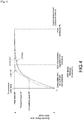
- Fig. 4 shows an example of opto-electronic conversion characteristics of the SDR and the HDR.
- the horizontal axis indicates an input luminance level and the vertical axis indicates a transmission code value.
- the broken line “a” indicates an SDR opto-electronic conversion characteristic (BT.709: gamma characteristic).
- the solid line “b” indicates an STD-B67 (HLG) characteristic, which is the characteristic of the HDR opto-electronic conversion.
- the long dashed short dashed line “c” indicates an ST2084 (PQ curve) characteristic, which is the characteristic of the HDR opto-electronic conversion.
- the STD-B67 (HLG) characteristic includes an area compatible with an SDR opto-electronic conversion characteristic (BT.709: gamma characteristic). That is, the curves of the both characteristics match until the input luminance level reaches a compatibility limit value of the both characteristics.
- the transmission code value is a compatibility level SP.
- the ST2084 (PQ curve) is a curve of a quantization step adapted for human eyes.
- the transmission code value is a peak level MP
- An HDR display reference threshold CL indicates a boundary between an area the luminance of which is to be matched with a luminance displayed on a monitor (CE monitor) in the receiver and an area depending on the CE monitor.
- the transmission code value is a threshold level CP.
- the transmission code value is the peak level MP.
- SL is 100 cd/m 2 .
- the video encoder 104 includes an encoding section 104b and an encoding section 104e.
- the encoding section 104b performs predictive coding such as H.264/AVC and H.265/HEVC on the SDR transmission video data V1' to obtain coded video data.
- the encoding section 104b predicts the SDR transmission video data V1'.
- the encoding section 104b generates, by the use of a stream formatter (not shown) at the subsequent stage, a video stream, i.e., a basic video stream STb including that coded video data.
- the encoding section 104b inserts the SDR conversion characteristic meta-information indicating the characteristic of the SDR opto-electronic conversion, into a layer of the basic video stream STb. That is, the encoding section 104b inserts SDR conversion characteristic meta-information "Transfer characteristics 1" indicating the SDR opto-electronic conversion characteristic (BT.709: gamma characteristic), into an area of video usability information (VUI) of an SPS NAL unit of an access unit (AU).
- SDR conversion characteristic meta-information indicating the characteristic of the SDR opto-electronic conversion characteristic
- VUI video usability information
- the encoding section 104e performs predictive coding such H.264/AVC and H.265/HEVC on the HDR transmission video data V2' to obtain coded video data.
- the encoding section 104e selectively predicts the HDR transmission video data V2' or the SDR transmission video data V1' for each coding block.
- the encoding section 104e generates, by the use of a stream formatter (not shown) at the subsequent stage, a video stream, i.e., an extended video stream STe including that coded video data.
- the encoding section 104e inserts HDR conversion characteristic meta-information indicating a characteristic of HDR opto-electronic conversion (e.g., STD-B67, ST2084) or a characteristic of HDR electro-optical conversion, which corresponds to the characteristic of the HDR opto-electronic conversion, and the meta-information for display control, into a layer of the extended video stream STe. That is, the encoding section 104e inserts a newly defined dynamic range SEI message including the HDR conversion characteristic meta-information "transfer_characteristics2" and the meta-information for display control, into a portion "Suffix_SEIs" of the access unit (AU), for example.
- HDR conversion characteristic meta-information indicating a characteristic of HDR opto-electronic conversion (e.g., STD-B67, ST2084) or a characteristic of HDR electro-optical conversion, which corresponds to the characteristic of the HDR opto-electronic conversion, and the meta-information for display control,
- Fig. 5 shows a structure example (Syntax) of a dynamic range SEI message.
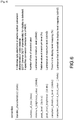
- Fig. 6 shows the contents (Semantics) of main information in the structure example.
- An eight-bit field of "transfer_characteristics2" indicates a characteristic of HDR opto-electronic conversion or a characteristic of HDR electro-optical conversion, which corresponds to the characteristic of the HDR opto-electronic conversion. If the meta-information "transfer_characteristics2" is present, the HDR-compliant reception apparatus 300 refers to the meta-information "transfer_characteristics2" preferentially rather than the meta-information "Transfer characteristics 1" inserted into the area of the VUI when displaying.
- An eight-bit field of "number_of bits” indicates the number of bits of an encoded pixel.
- a sixteen-bit field of "minimum_brightness_value” indicates a luminance (cd/m 2 ) at a minimum level.
- a sixteen-bit field of "peak level” indicates a relative value (%) at a maximum level.
- a sixteen-bit field of "peak level brightness” indicates a luminance (cd/m 2 ) at a maximum level and corresponds to the peak luminance PL in Fig. 4 .
- "Peak_level” of "peak level brightness” enables selection of an image processing method used in forming a display image suitable for display capability after a histogram of the image is determined, for example, to be performed.
- a sixteen-bit field of "compliant_threshold_level” indicates a threshold (%) in display level mapping.
- a sixteen-bit field of "compliant_threshold_level_value” indicates a luminance (cd/m 2 ) that is the threshold in the display level mapping, and corresponds to the HDR display reference threshold CL in Fig. 4 .
- the system encoder 105 generates the transport stream TS including the basic video stream STb and the extended video stream STe, which are generated by the video encoder 104.
- the transmitter 106 sends the transport stream TS to the reception apparatuses 200, 300 through broadcasting waves or network packets.
- the SDR video data V1 is supplied to the SDR opto-electronic converter 102.
- the SDR opto-electronic converter 102 applies the SDR opto-electronic conversion characteristic (BT.709: gamma characteristic) to the SDR video data V1 to obtain the SDR transmission video data V1' that is the SDR video data for transmission.
- SDR opto-electronic conversion characteristic BT.709: gamma characteristic
- the HDR video data V2 is supplied to the HDR opto-electronic converter 103.
- the HDR opto-electronic converter 103 applies the HDR opto-electronic conversion characteristic (e.g., STD-B67, ST2084) to the HDR video data V2 to obtain the HDR transmission video data V2' that is the HDR video data for transmission.
- the HDR opto-electronic conversion characteristic e.g., STD-B67, ST2084
- the SDR transmission video data V1' obtained by the SDR opto-electronic converter 102 is supplied to the encoding section 104b and the encoding section 104e of the encoder 104.
- the encoding section 104b performs predictive coding such H.264/AVC and H.265/HEVC on the SDR transmission video data V1' to obtain the coded video data.
- the basic video stream STb that is a video stream including that coded video data is generated.
- the encoding section 104b inserts the SDR conversion characteristic meta-information indicating the characteristic of the SDR opto-electronic conversion, into the layer of the basic video stream STb.
- the SDR conversion characteristic meta-information "Transfer characteristics 1" including the SDR opto-electronic conversion characteristic (BT.709: gamma characteristic) is inserted into the area of the VUI of the SPS NAL unit of the access unit (AU).
- the HDR transmission video data V2' obtained by the HDR opto-electronic converter 103 is supplied to the encoding section 104e of the encoder 104.
- the encoding section 104e uses the SDR transmission video data V1' with respect to the HDR transmission video data V2', the encoding section 104e performs predictive coding such as H.264/ AVC and H.265/HEVC to obtain the coded video data.
- the extended video stream STe that is a video stream including that coded video data is generated.
- the encoding section 104e inserts HDR conversion characteristic meta-information indicating a HDR opto-electronic conversion characteristic (e.g., STD-B67, ST2084) or a characteristic of HDR electro-optical conversion, which corresponds to the characteristic of the HDR opto-electronic conversion, and the meta-information for display control, into the layer of the extended video stream STe.
- the dynamic range SEI message including the HDR conversion characteristic meta-information "transfer_characteristics2" and the meta-information for display control is inserted into the portion "Suffix_SEIs" of the access unit (AU), for example.
- the basic video stream STb generated by the encoding section 104b of the video encoder 104 is supplied to the system encoder 105. Further, the extended video stream STe generated by the encoding section 104e of the video encoder 104 is supplied to the system encoder 105.
- the system encoder 105 PES-packetizes, transport packetizes, and multiplexes each of the basic video stream STb and the extended video stream STe to obtain the transport stream TS that is the container stream (multiplexed stream).
- the transport stream TS is sent to the reception apparatuses 200, 300 by the transmitter 106 through broadcasting waves or network packets.
- Fig. 7 shows a configuration example of the transport stream TS.
- the transport stream TS includes the two video streams, i.e., the basic video stream STb and the extended video stream STe.
- a PES packet "video PES" of each video stream is present.
- a packet identifier (PID) of the basic video stream STb is, for example, PID1.
- the basic video stream STb includes coded video data obtained by subjecting the SDR transmission video data V1' to predictive coding.
- an NAL unit such as STb, AUD, VPS, SPS, PPS, PSEI, SLICE, SSEI, and EOS is present.
- Nuh_layer_id in the header of each NAL unit is, for example, "0", which indicates that it is the basic video stream STb according to the coded video data.
- the SDR conversion characteristic meta-information "Transfer characteristics 1" indicating the characteristic (BT.709: gamma characteristic) of the SDR opto-electronic conversion is inserted into the area of the VUI of the NAL unit that is the SPS.
- the packet identifier (PID) of the extended video stream STe is, for example, PID2.
- the extended video stream STe includes coded video data obtained by subjecting the HDR transmission video data V2' to predictive coding using the SDR transmission video data V1'.
- an NAL unit such as AUD, PPS, PSEI, SLICE, SSEI, and EOS is present.
- Nuh_layer_id in the header of each NAL unit is, for example, "1", which indicates that it is the extended video stream STe according to the coded video data.
- the dynamic range SEI message in which the HDR conversion characteristic meta-information "Transfer characteristics 2" and the meta-information for display control are described is inserted into the access unit.
- the transport stream TS includes a program map table (PMT) as program specific information (PSI).
- the PSI is information describing which program each elementary stream of the transport stream belongs to.
- a program loop describing information related to the entire program is present in the PMT. Further, an elementary stream loop including information related to each elementary stream is present in the PMT.
- two video elementary stream loops are present corresponding to the two video streams, i.e., the basic video stream STb and the extended video stream STe.
- Information on the stream type (ST0), the packet identifier (PID1), and the like is provided in the video elementary stream loop corresponding to the basic video stream STb. Further, information on the stream type (ST1), the packet identifier (PID2), and the like is provided in the video elementary stream loop corresponding to the extended video stream STe.
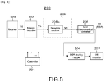
- the reception apparatus 200 is an SDR-compliant reception apparatus as described above.
- the reception apparatus 200 includes a controller 201, a receiver 202, a system decoder 203, a video decoder 204, an SDR electro-optical converter 205, an SDR display mapper 206, and a CE monitor 207.
- the controller 201 includes a central processing unit (CPU) and controls operations of the respective sections of the reception apparatus 200 according to a control program.
- CPU central processing unit
- the receiver 202 receives the transport stream TS sent from the transmission apparatus 100 through broadcasting waves or network packets.
- the transport stream TS includes two video streams, i.e., the basic video stream STb and the extended video stream STe.
- the basic video stream STb includes coded video data obtained by subjecting the SDR transmission video data to predictive coding.
- the SDR transmission video data is obtained by performing SDR opto-electronic conversion on the SDR video data.
- the extended video stream STe includes coded video data obtained by subjecting HDR transmission video data to predictive coding using the SDR transmission video data.
- the HDR transmission video data is obtained by performing HDR opto-electronic conversion on the HDR video data.
- the SDR conversion characteristic meta-information indicating the characteristic of the SDR opto-electronic conversion is inserted into the area of the SPS NAL unit of the basic video stream. Further, the HDR conversion characteristic meta-information indicating the characteristic of the HDR opto-electronic conversion or the characteristic of HDR electro-optical conversion, which corresponds to the characteristic of the HDR opto-electronic conversion, is inserted into the area of the SEI NAL unit of the extended video stream.
- the system decoder 203 extracts the basic video stream STb from the transport stream TS.
- the video decoder 204 includes a decoding section 204b.
- the decoding section 204b decodes the basic video stream STb, which is extracted by the system decoder 203, to obtain the SDR transmission video data V1'.
- the decoding section 204b performs processing inverse to that of the encoding section 104b of the video encoder 104 of Fig. 2 .
- the decoding section 204b extracts a parameter set and an SEI message, which are inserted into each access unit of the basic video stream STb, and sends the parameter set and the SEI message to the controller 201.
- the controller 201 recognizes the SDR opto-electronic conversion characteristic (BT.709: gamma characteristic) on the basis of the SDR conversion characteristic meta-information "Transfer characteristics 1" in the video usability information (VUI) of the SPS.
- the controller 201 sets an SDR electro-optical conversion characteristic that is a characteristic inverse to the SDR opto-electronic conversion characteristic, in the SDR electro-optical converter 205.
- the SDR electro-optical converter 205 applies the SDR electro-optical conversion characteristic to the transmission video data V1', which is output from the video decoder 204, to obtain the SDR video data V1.
- the SDR display mapper 206 adjusts the display luminance of the SDR video data V1 obtained by the SDR electro-optical converter 205. That is, if a luminance corresponding to the maximum luminance display capability of the CE monitor 207 is higher than the SDR characteristic expression limit luminance SL (see Fig. 4 ), the SDR display mapper 206 performs display mapping, i.e., luminance conversion such that a maximum display luminance level is equal to a luminance level corresponding to the maximum luminance display capability of the CE monitor 207.
- the receiver 202 receives a transport stream TS sent from the transmission apparatus 100 through broadcasting waves or network packets.
- the transport stream TS is supplied to the system decoder 203.
- the system decoder 203 extracts a basic video stream STb from the transport stream TS.
- the basic video stream STb extracted by the system decoder 203 is supplied to the decoding section 204b of the video decoder 204.
- the decoding section 204b decodes the basic video stream STb to obtain the SDR transmission video data V1'. Further, the decoding section 204b extracts a parameter set and an SEI message, which are inserted into the basic video stream STb, and sends the parameter set and the SEI message to the controller 201.
- the controller 201 recognizes the SDR opto-electronic conversion characteristic (BT.709: gamma characteristic) on the basis of the SDR conversion characteristic meta-information "Transfer characteristics 1" in the video usability information (VUI) of the SPS. Then, the SDR electro-optical conversion characteristic that is a characteristic inverse to the SDR opto-electronic conversion characteristic is set in the SDR electro-optical converter 205 under the control of the controller 201.
- BT.709 gamma characteristic
- the SDR transmission video data V1' obtained by the video decoder 204 (decoding section 204b) is supplied to the SDR electro-optical converter 205.
- the SDR electro-optical converter 205 applies the SDR electro-optical conversion characteristic to the SDR transmission video data V1' to obtain the SDR video data V1 that is video data for display.
- the SDR video data V1 obtained by the SDR electro-optical converter 205 is supplied to the SDR display mapper 206.
- the SDR display mapper 206 adjusts the display luminance of the SDR video data V1. That is, if the luminance corresponding to the maximum luminance display capability of the CE monitor 207 is higher than the SDR characteristic expression limit luminance SL, the SDR display mapper 206 performs display mapping, i.e., luminance conversion such that the maximum display luminance level is equal to the luminance level corresponding to the maximum luminance display capability of the CE monitor 207.
- the output video data of the SDR display mapper 206 is supplied to the CE monitor 207.
- the SDR image is displayed on the CE monitor 207, using the SDR video data the display luminance of which has been adjusted.
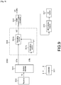
- the reception apparatus 300 is an HDR-compliant reception apparatus as described above.
- the reception apparatus 300 includes a controller 301, a receiver 302, a system decoder 303, a video decoder 304, an HDR electro-optical converter 305, an HDR display mapper 306, and a CE monitor 307.
- the controller 301 includes a central processing unit (CPU) and controls operations of the respective sections of the reception apparatus 300 according to a control program.
- the receiver 302 receives the transport stream TS sent from the transmission apparatus 100 through broadcasting waves or network packets.
- the transport stream TS includes two video streams, i.e., the basic video stream STb and the extended video stream STe.
- the basic video stream STb includes coded video data obtained by subjecting the SDR transmission video data to predictive coding.
- the SDR transmission video data is obtained by performing the SDR opto-electronic conversion on the SDR video data.
- the extended video stream STe includes coded video data obtained by subjecting HDR transmission video data to predictive coding using the SDR transmission video data.
- the HDR transmission video data is obtained by performing HDR opto-electronic conversion on the HDR video data.
- the SDR conversion characteristic meta-information indicating the characteristic of the SDR opto-electronic conversion is inserted into the area of the SPS NAL unit of the basic video stream. Further, the HDR conversion characteristic meta-information indicating the characteristic of the HDR opto-electronic conversion or the characteristic of HDR electro-optical conversion, which corresponds to the characteristic of the HDR opto-electronic conversion, is inserted into the area of the SEI NAL unit of the extended video stream.
- the system decoder 303 extracts the basic video stream STb and the extended video stream STe from the transport stream TS.
- the video decoder 304 includes decoding sections 304b, 304e.
- the decoding section 304b decodes the basic video stream STb, which is extracted by the system decoder 303, to obtain the SDR transmission video data V1'.
- the decoding section 304b performs processing inverse to that of the encoding section 104b of the video encoder 104 of Fig. 2 .
- the decoding section 304b extracts the parameter set and the SEI message, which are inserted into each access unit of the basic video stream STb, and sends the parameter set and the SEI message to the controller 301.
- the decoding section 304e decodes the extended video stream STe, which is extracted by the system decoder 303, to obtain the HDR transmission video data V2'.
- the decoding section 304e performs processing inverse to that of the encoding section 104e of the video encoder 104 of Fig. 2 .
- the decoding section 304e extracts the parameter set and the SEI message, which are inserted into each access unit of the extended video stream STe, and sends the parameter set and the SEI message to the controller 301.
- the controller 301 recognizes the HDR opto-electronic conversion characteristic (e.g., STD-B67, ST2084) on the basis of the HDR conversion characteristic meta-information "Transfer characteristics 2" in the dynamic range SEI message.
- the controller 301 sets an HDR electro-optical conversion characteristic that is a characteristic inverse to the HDR opto-electronic conversion characteristic, in the HDR electro-optical converter 305.
- the HDR electro-optical converter 305 applies the HDR electro-optical conversion characteristic to the HDR transmission video data V2', which is output from the video decoder 304 (decoding section 304e), to obtain the HDR video data V2 that is video data for display.
- the HDR display mapper 306 adjusts the display luminance of the HDR video data V2 obtained by the HDR electro-optical converter 305 on the basis of the meta-information for display control in the dynamic range SEI message under the control of the controller 301. Such adjustment of the display luminance will be described.
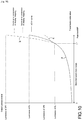
- Fig. 10 shows an example of the adjustment of the display luminance.
- the horizontal axis indicates a transmission code value, which corresponds to the vertical axis of Fig. 4 .
- the vertical axis indicates an output luminance level (display luminance level), which corresponds to the horizontal axis of Fig. 4 .
- the solid line "a" is an EOTF curve indicating the HDR electro-optical conversion characteristic.
- the transmission code value is a peak level MP
- the output luminance level is PL.
- the transmission code value is a threshold level CP
- the output luminance level is CL.
- the output luminance level corresponding to a value that is the transmission code value larger than the threshold level CP is assigned to a range up to a maximum display luminance level DP1 of the CE monitor 307 by processing in the HDR display mapper 306 (processing of increasing the luminance).
- the long dashed double-short dashed line "b" shows an example of the luminance conversion in this case.
- the output luminance level corresponding to the value that is the transmission code value larger than the threshold level CP is assigned to a range up to a maximum display luminance level DP2 of the CE monitor 307 by processing in the HDR display mapper 306 (processing of decreasing the luminance).
- the long dashed short dashed line "c" shows an example of the luminance conversion in this case.
- the receiver 302 receives a transport stream TS sent from the transmission apparatus 100 through broadcasting waves or network packets.
- the transport stream TS is supplied to the system decoder 303.
- the system decoder 303 extracts a basic video stream STb and an extended video stream STe from the transport stream TS.
- the basic video stream STb which is extracted by the system decoder 303, is supplied to the decoding section 304b of the video decoder 304.
- the decoding section 304b decodes the basic video stream STb to obtain the SDR transmission video data V1'. Further, the decoding section 304b extracts a parameter set and an SEI message, which are inserted into the basic video stream STb, and sends the parameter set and the SEI message to the controller 301.
- the extended video stream STe extracted by the system decoder 303 is supplied to the decoding section 304e of the video decoder 304.
- the decoding section 304e decodes the extended video stream STe to obtain the HDR transmission video data V2'.
- a decoding section 304e extracts the parameter set and the SEI message, which are inserted into each access unit of the extended video stream STe, and sends the parameter set and the SEI message to the controller 301.
- the controller 301 recognizes the HDR opto-electronic conversion characteristic (e.g., STD-B67, ST2084) on the basis of the HDR conversion characteristic meta-information "Transfer characteristics 2" in the dynamic range SEI message. Then, the HDR electro-optical conversion characteristic that is a characteristic inverse to the HDR opto-electronic conversion characteristic is set in the HDR electro-optical converter 305.
- the HDR opto-electronic conversion characteristic e.g., STD-B67, ST2084
- the HDR electro-optical conversion characteristic that is a characteristic inverse to the HDR opto-electronic conversion characteristic is set in the HDR electro-optical converter 305.
- the HDR transmission video data V2' obtained by the video decoder 304 (decoding section 304e) is supplied to the HDR electro-optical converter 305.
- the HDR electro-optical converter 305 applies the HDR electro-optical conversion characteristic to the HDR transmission video data V2' to obtain the HDR video data V2 that is video data for display.
- the HDR video data V2 obtained by the HDR electro-optical converter 305 is supplied to the HDR display mapper 306.
- the HDR display mapper 306 adjusts the display luminance of the HDR video data V2 on the basis of the meta-information for display control in the dynamic range SEI message (see Fig. 10 ).
- the output video data of the HDR display mapper 306 is supplied to the CE monitor 307.
- the HDR image is displayed on the CE monitor 307, using the HDR video data the display luminance of which has been adjusted.
- the HDR conversion characteristic meta-information is inserted into the area of the SEI NAL unit of the extended video stream STe and sent.
- the HDR-compliant receiver it becomes possible for the HDR-compliant receiver to suitably perform electro-optical conversion processing on the HDR transmission video data V2' obtained by processing the basic video stream STb and the extended video stream STe on the basis of the HDR conversion characteristic meta-information.
- the SDR conversion characteristic meta-information is inserted into the area of the SPS NAL unit of the basic video stream STb and sent.
- the SDR-compliant receiver it becomes possible for the SDR-compliant receiver to suitably perform electro-optical conversion processing on the SDR transmission video data V1' obtained by processing the basic video stream STb on the basis of the SDR conversion characteristic meta-information.
- the meta-information for display control is inserted into the area of the SEI NAL unit of the extended video stream STe together with the HDR conversion characteristic meta-information and sent. Therefore, it is possible for the HDR-compliant receiver to suitably control the display luminance using the meta-information for display control.
- the meta-information for display control includes area information indicating an area in which luminance conversion is allowed. The luminance conversion according to the display-luminance capability of the CE monitor, for example, is performed only in the area in which luminance conversion is allowed. Thus, it becomes possible to favorably reproduce video having a luminance intended by a producer.
- the meta-information indicating the characteristic of the HDR opto-electronic conversion is inserted into the area of the SEI NAL unit of the extended video stream STe.
- the meta-information indicating the characteristic of the HDR opto-electronic conversion is inserted into the area of the SEI NAL unit of the basic video stream STb.
- the HDR-compliant receiver it becomes possible for the HDR-compliant receiver to suitably perform electro-optical conversion processing on the HDR transmission video data V2' on the basis of the meta-information indicating the characteristic of the HDR opto-electronic conversion.
- the present technology is also applicable to a case of transmitting a video stream according to the HDR transmission video data V2' obtained by applying the characteristic of the HDR opto-electronic conversion that is the hybrid log-gamma (e.g., STD-B67) to, for example, the HDR video data, as a video stream for downward compatibility with the SDR.
- the meta-information indicating the characteristic of the HDR opto-electronic conversion is inserted into the area of the SEI NAL unit of the video stream.
- the HDR-compliant receiver it becomes possible for the HDR-compliant receiver to suitably perform electro-optical conversion processing on the HDR transmission video data V2' on the basis of the meta-information indicating the characteristic of the HDR opto-electronic conversion.
- the example in which, in the reception apparatus 200, 300, the electro-optical conversion processing is performed by the electro-optical converter 205, 305 and the adjustment of the display luminance according to the maximum luminance display capability of the CE monitor 207, 307 is performed by the display mapper 206, 306 has been shown.
- the electro-optical conversion processing and the adjustment of the display luminance can be performed only by the electro-optical converter 205, 305 at the same time.
- the container is the transport stream (MPEG-2 TS)
- MPEG-2 TS transport stream
- the present technology is not limited to the case where the TS is used as the transport.
- the layer of the video can be realized by the identical method also in the case of using other packets such as ISO base media file format (ISOBMFF) and MPEG Media Transport (MMT).
- ISO base media file format ISO base media file format
- MMT MPEG Media Transport
- a main feature of the present technology is to insert the HDR conversion characteristic meta-information into the area of the SEI NAL unit of the video stream and send it, such that the HDR-compliant receiver can suitably perform electro-optical conversion processing on the HDR transmission video data on the basis of the HDR conversion characteristic meta-information (see Figs. 5 and 7 ), the HDR conversion characteristic meta-information indicating the characteristic of the HDR opto-electronic conversion or the characteristic of HDR electro-optical conversion, which corresponds to the characteristic of the HDR opto-electronic conversion.
Landscapes
- Engineering & Computer Science (AREA)
- Multimedia (AREA)
- Signal Processing (AREA)
- Library & Information Science (AREA)
- Two-Way Televisions, Distribution Of Moving Picture Or The Like (AREA)
- Compression Or Coding Systems Of Tv Signals (AREA)
- Picture Signal Circuits (AREA)
- Television Signal Processing For Recording (AREA)
- Studio Devices (AREA)
Abstract
Description
- This application claims the benefit of Japanese Priority Patent Application
JP 2015-257206 filed December 28, 2015 - The present technology relates to a transmission apparatus, a transmission method, a reception apparatus, and a reception method, and more particularly to a transmission apparatus, for example, that sends transmission video data obtained by performing high dynamic range opto-electronic conversion on high dynamic range video data.
- From the past, sending transmission video data obtained by performing high dynamic range opto-electronic conversion on high dynamic range video data has been considered. For example, NPL 1 describes, for reception by a traditional receiver, a high dynamic range opto-electronic conversion characteristic (new gamma characteristic) including an area compatible with a traditional opto-electronic conversion characteristic (gamma characteristic).
- [NPL 1]
Tim Borer, "Non-Linear Opto-Electrical Transfer Functions for High Dynamic Range Television", Research & Development White Paper WHP 283, July 2014 - For example, in the case of sending the above-mentioned transmission video data obtained using the high dynamic range opto-electronic conversion characteristic including the area compatible with the traditional opto-electronic conversion characteristic, it is necessary that the traditional receiver can judge that the opto-electronic conversion characteristic is the same as the traditional opto-electronic conversion characteristic and a high dynamic range-compliant receiver can judge that the opto-electronic conversion characteristic is the high dynamic range opto-electronic conversion characteristic.
- The present technology has been made for enabling a high dynamic range-compliant receiver to suitably perform electro-optical conversion processing on transmission video data resulting from high dynamic range opto-electronic conversion.
- According to an embodiment of present technology, there is provided a transmission apparatus including:
- an opto-electronic converter configured to perform high dynamic range opto-electronic conversion on high dynamic range video data to obtain high dynamic range transmission video data;
- an encoder configured to receive input of at least the high dynamic range transmission video data and output a video stream including coded video data;
- a transmitter configured to send the video stream; and
- an information inserter configured to insert high dynamic range conversion characteristic meta-information into an area of a supplemental enhancement information (SEI) network abstraction layer (NAL) unit of the video stream, the high dynamic range conversion characteristic meta-information indicating a characteristic of the high dynamic range opto-electronic conversion or a characteristic of high dynamic range electro-optical conversion, which corresponds to the characteristic of the high dynamic range opto-electronic conversion.
- In the embodiment of the present technology, the opto-electronic converter performs the high dynamic range opto-electronic conversion on the high dynamic range video data to obtain the high dynamic range transmission video data. For example, the characteristic of the high dynamic range opto-electronic conversion includes various characteristics such as STD-B67 (hybrid log-gamma) and ST2084 (PQ curve). The encoding section receives the input of at least the high dynamic range transmission video data and outputs the video stream including the coded video data. The transmitter sends the video stream. The information inserter inserts the high dynamic range conversion characteristic meta-information into the area of the SEI NAL unit of the video stream. The high dynamic range conversion characteristic meta-information indicates the characteristic of the high dynamic range opto-electronic conversion or the characteristic of the high dynamic range electro-optical conversion, which corresponds to the characteristic of the high dynamic range opto-electronic conversion.
- As described above, in the embodiment of the present technology, the high dynamic range conversion characteristic meta-information is inserted into the area of the SEI NAL unit of the video stream. Thus, a high dynamic range-compliant receiver can suitably perform electro-optical conversion processing on the high dynamic range transmission video data on the basis of the high dynamic range conversion characteristic meta-information.
- Note that, in the embodiment of the present technology, for example, the encoder may be further configured to receive input of standard dynamic range transmission video data obtained by performing standard dynamic range opto-electronic conversion on standard dynamic range video data, together with the high dynamic range transmission video data, and output a basic video stream including coded video data of the standard dynamic range transmission video data and an extended video stream including coded video data of a difference between the high dynamic range transmission video data and the standard dynamic range transmission video data. The information inserter may be further configured to insert the high dynamic range conversion characteristic meta-information into an area of an SEI NAL unit of the extended video stream, and insert standard dynamic range conversion characteristic meta-information into an area of a sequence parameter set (SPS) NAL unit of the basic video stream, the standard dynamic range conversion characteristic meta-information indicating a characteristic of the standard dynamic range opto-electronic conversion. The term "extended" is used herein to also refer to "enhancement".
- In this case, the high dynamic range-compliant receiver can obtain the high dynamic range transmission video data from the basic video stream and the extended video stream. Then, the high dynamic range-compliant receiver can suitably perform electro-optical conversion processing on the high dynamic range transmission video data on the basis of the high dynamic range conversion characteristic meta-information inserted into the area of the SEI NAL unit of the extended video stream to obtain the video data for display. Further, the standard dynamic range-compliant receiver can obtain the standard dynamic range transmission video data from the basic video stream. Then, the standard dynamic range-compliant receiver can suitably perform electro-optical conversion processing on the standard dynamic range transmission video data on the basis of the standard dynamic range conversion characteristic meta-information inserted into the area of the SPS NAL unit of the basic video stream to obtain the video data for display.
- Further, in the embodiment of the present technology, for example, the information inserter may be further configured to insert meta-information for display control into the area of the SEI NAL unit together with the high dynamic range conversion characteristic meta-information. In this case, for example, the meta-information for display control may include peak luminance information. Further, for example, the meta-information for display control further may include area information indicating an area in which luminance conversion is allowed. In this case, the high dynamic range-compliant receiver can suitably control a display luminance using the meta-information for display control.
- Further, according to another embodiment of the present technology, there is provided a reception apparatus, including:
- a receiver configured to receive a video stream;
- a decoder configured to decode the video stream to obtain high dynamic range transmission video data, the video stream including an area of an SEI NAL unit, into which high dynamic range conversion characteristic meta-information is inserted, the high dynamic range conversion characteristic meta-information indicating a characteristic of high dynamic range opto-electronic conversion or a characteristic of high dynamic range electro-optical conversion, which corresponds to the characteristic of the high dynamic range opto-electronic conversion; and
- an electro-optical converter configured to perform high dynamic range electro-optical conversion on the high dynamic range transmission video data on the basis of the meta-information indicating the high dynamic range conversion characteristic to obtain video data for display.
- In the embodiment of the present technology, the receiver receives the video stream. The decoding section decodes the video stream to obtain the high dynamic range transmission video data. The high dynamic range conversion characteristic meta-information is inserted into the area of the SEI NAL unit of the video stream. The high dynamic range conversion characteristic meta-information indicates the characteristic of the high dynamic range opto-electronic conversion or the characteristic of the high dynamic range electro-optical conversion, which corresponds to the characteristic of the high dynamic range opto-electronic conversion. The electro-optical converter performs high dynamic range electro-optical conversion on the high dynamic range transmission video data on the basis of the high dynamic range conversion characteristic meta-information to obtain the video data for display.
- For example, the receiver may be further configured to receive a basic (the terms "basic" and "base" are used interchangeably herein) video stream including coded video data of the standard dynamic range transmission video data and an extended video stream including coded video data of a difference between the high dynamic range transmission video data and the standard dynamic range transmission video data. The decoder may be further configured to decode the basic video stream to obtain the standard dynamic range transmission video data, and decode the extended video stream using the standard dynamic range transmission video data to obtain the high dynamic range transmission video data. The high dynamic range conversion characteristic meta-information may be inserted into an area of an SEI NAL unit of the extended video stream.
- As described above, in the embodiment of the present technology, the electro-optical conversion is performed on the high dynamic range transmission video data to obtain the video data for display on the basis of the high dynamic range conversion characteristic meta-information inserted into the area of the SEI NAL unit of the video stream. Thus, it is possible to suitably perform electro-optical conversion on the high dynamic range transmission video data to obtain favorable high dynamic range video data as the video data for display.
- Note that, in the embodiment of the present technology, for example, peak luminance information may be further inserted into the area of the SEI NAL unit. The reception apparatus may further include a luminance adjuster configured to adjust a display luminance of the video data for display on the basis of the peak luminance information. Such adjustment of the display luminance based on the peak luminance information makes it possible to suitably adjust the display luminance according to the display-luminance capability of a monitor.
- Further, in this case, for example, area information indicating an area in which luminance conversion is allowed may be further inserted into the area of the SEI NAL unit, and the luminance adjuster may be further configured to adjust the display luminance in the area in which luminance conversion is allowed, on the basis of the area information indicating the area in which luminance conversion is allowed. Such adjustment of the display luminance in the area in which luminance conversion is allowed makes it possible to favorably reproduce video having a luminance intended by a producer.
- In accordance with the embodiments of the present technology, electro-optical conversion processing on transmission video data resulting from high dynamic range opto-electronic conversion can be suitably performed by a high dynamic range-compliant receiver. It should be noted that effects described herein are merely examples and are not limitative and additional effects may be provided.
-
- [
Fig. 1 ]
Fig. 1 is a block diagram showing a configuration example of a transmission and reception system according to an embodiment. - [
Fig. 2 ]
Fig. 2 is a block diagram showing a configuration example of a transmission apparatus constituting the transmission and reception system. - [
Fig. 3 ]
Fig. 3 is a block diagram showing a configuration example of a video data generator that generates SDR video data V1 and HDR video data V2. - [
Fig. 4 ]
Fig. 4 is a diagram showing an example of opto-electronic conversion characteristics of SDR and HDR. - [
Fig. 5 ]
Fig. 5 is a diagram showing a structure example of a dynamic range SEI message. - [
Fig. 6 ]
Fig. 6 is a diagram showing the contents of main information in the structure example of the dynamic range SEI message. - [
Fig. 7 ]
Fig. 7 is a diagram showing a configuration example of a transport stream TS. - [
Fig. 8 ]
Fig. 8 is a block diagram showing a configuration example of a traditional reception apparatus compliant with the SDR (incompliant with the HDR), which constitutes the transmission and reception system. - [
Fig. 9 ]
Fig. 9 is a block diagram showing a configuration example of an HDR-compliant reception apparatus, which constitutes the transmission and reception system. - [
Fig. 10 ]
Fig. 10 is a diagram showing an example of adjustment of a display luminance in an HDR display mapper. - Hereinafter, an embodiment will be described. Note that descriptions thereof will be made in the following order.
- 1. Embodiment
- 2. Modified Example
-
Fig. 1 shows a configuration example of a transmission andreception system 10 according to the embodiment. The transmission andreception system 10 is constituted of atransmission apparatus 100 andreception apparatuses reception apparatus 200 is a reception apparatus compliant with a traditional standard dynamic range (SDR) and incompliant with a high dynamic range (HDR). Thereception apparatus 300 is an HDR-compliant reception apparatus. - The
transmission apparatus 100 sends an MPEG-2 transport stream (hereinafter, simply referred to as "transport stream TS") through broadcasting waves or network packets. The transport stream TS is a container stream (multiplexed stream). The transport stream TS includes video streams such as HEVC and AVC video streams, in this embodiment, two video streams, i.e., a basic video stream and an extended video stream. - The basic video stream includes coded video data obtained by subjecting SDR transmission video data to predictive coding. The SDR transmission video data is obtained by performing SDR opto-electronic conversion on SDR video data. The extended video stream includes coded video data obtained by subjecting HDR transmission video data to predictive coding using the SDR transmission video data. The HDR transmission video data is obtained by performing HDR opto-electronic conversion on HDR video data.
- HDR conversion characteristic meta-information is inserted into the video stream, in this embodiment, an area of an SEI NAL unit of the extended video stream.
The HDR conversion characteristic meta-information indicates a characteristic (e.g., STD-B67, ST2084) of the HDR opto-electronic conversion or a characteristic of HDR electro-optical conversion, which corresponds to the characteristic of the HDR opto-electronic conversion. Then, SDR conversion characteristic meta-information is inserted into the video stream, in this embodiment, an area of an SPS NAL unit of the basic video stream. The SDR conversion characteristic meta-information indicates a characteristic (BT.709: gamma characteristic) of the SDR opto-electronic conversion. - Further, meta-information for display control is inserted into the video stream, in this embodiment, the area of the SEI NAL unit of the extended video stream together with the HDR conversion characteristic meta-information. The meta-information for display control includes peak luminance information, area information indicating an area in which luminance conversion is allowed, and the like.
- The
reception apparatus 200 receives the transport stream TS sent from thetransmission apparatus 100 through broadcasting waves or network packets. The transport stream TS includes the video streams, in this embodiment, the two video streams, i.e., the basic video stream and the extended video stream as described above. Then, the SDR conversion characteristic meta-information is inserted into the received video stream, in this embodiment, the area of the SPS NAL unit of the basic video stream. - The
reception apparatus 200 extracts, from the transport stream TS, a necessary video stream, here, the basic video stream and decodes the extracted stream to obtain SDR transmission video data. Thereception apparatus 200 suitably performs electro-optical conversion processing on the SDR transmission video data on the basis of the SDR conversion characteristic meta-information to obtain SDR video data that is video data for display. Further, thereception apparatus 200 performs display mapping, i.e., adjustment of a display luminance on the video data for display on the basis of a peak luminance (100 cd/m2), the maximum display luminance of a monitor, or the like. - The
reception apparatus 300 receives the transport stream TS sent from thetransmission apparatus 100 through broadcasting waves or network packets. The transport stream TS includes the video streams, in this embodiment, the two video streams, i.e., the basic video stream and the extended video stream as described above. Then, the HDR conversion characteristic meta-information is inserted into the received video stream, in this embodiment, the area of the SEI NAL unit of the extended video stream. - The
reception apparatus 300 extracts, from the transport stream TS, a necessary video stream, here, both of the basic video stream and the extended video stream and decodes the extracted streams to obtain HDR transmission video data. Thereception apparatus 300 suitably performs electro-optical conversion processing on the HDR transmission video data on the basis of the HDR conversion characteristic meta-information to obtain HDR video data that is video data for display. Further, thereception apparatus 300 performs display mapping, i.e., adjustment of the display luminance on the video data for display on the basis of the meta-information for display control, the maximum display luminance of a monitor, or the like, which is inserted together with the HDR conversion characteristic meta-information. -
Fig. 2 shows a configuration example of thetransmission apparatus 100. Thetransmission apparatus 100 handles SDR video data V1 and HDR video data V2. Provided that the white peak luminance of a traditional SDR image is 100%, the HDR video data V2 has a luminance ranging from 0 to 100%∗N, for example, 0 to 1000% or more. -
Fig. 3 shows a configuration example of avideo data generator 150 that generates the SDR video data V1 and the HDR video data V2. Thevideo data generator 150 includes aHDR camera 151 and adynamic range converter 153. TheHDR camera 151 images a subject and outputs the HDR video data V2. Thedynamic range converter 153 converts the HDR video data V2, which is output from theHDR camera 151, from the HDR to the SDR. Then,dynamic range converter 153 outputs the SDR video data V1. - Referring back to
Fig. 2 , thetransmission apparatus 100 includes acontroller 101, an SDR opto-electronic converter 102, an HDR opto-electronic converter 103, avideo encoder 104, asystem encoder 105, and atransmitter 106. Thecontroller 101 includes a central processing unit (CPU) and controls operations of the respective sections of thetransmission apparatus 100 according to a control program. - The SDR opto-
electronic converter 102 applies the SDR opto-electronic conversion characteristic (BT.709: gamma characteristic) to the SDR video data V1 to obtain SDR video data for transmission, i.e., SDR transmission video data V1'. The HDR opto-electronic converter 103 applies the HDR opto-electronic conversion characteristic (e.g., STD-B67, ST2084) to the HDR video data V2 to obtain HDR video data for transmission, i.e., HDR transmission video data V2'. -
Fig. 4 shows an example of opto-electronic conversion characteristics of the SDR and the HDR. In this figure, the horizontal axis indicates an input luminance level and the vertical axis indicates a transmission code value. The broken line "a" indicates an SDR opto-electronic conversion characteristic (BT.709: gamma characteristic). The solid line "b" indicates an STD-B67 (HLG) characteristic, which is the characteristic of the HDR opto-electronic conversion. The long dashed short dashed line "c" indicates an ST2084 (PQ curve) characteristic, which is the characteristic of the HDR opto-electronic conversion. - The STD-B67 (HLG) characteristic includes an area compatible with an SDR opto-electronic conversion characteristic (BT.709: gamma characteristic). That is, the curves of the both characteristics match until the input luminance level reaches a compatibility limit value of the both characteristics. When the input luminance level is the compatibility limit value, the transmission code value is a compatibility level SP. The ST2084 (PQ curve) is a curve of a quantization step adapted for human eyes. In the HDR opto-electronic conversion characteristic, when the input luminance level is a peak luminance PL, the transmission code value is a peak level MP
- An HDR display reference threshold CL indicates a boundary between an area the luminance of which is to be matched with a luminance displayed on a monitor (CE monitor) in the receiver and an area depending on the CE monitor. When the input luminance level is a compatibility limit value CL, the transmission code value is a threshold level CP. Note that, in the SDR opto-electronic conversion characteristic, when the input luminance level is an SDR characteristic expression limit luminance SL, the transmission code value is the peak level MP. Here, SL is 100 cd/m2.
- Referring back to
Fig. 2 , thevideo encoder 104 includes anencoding section 104b and anencoding section 104e. Theencoding section 104b performs predictive coding such as H.264/AVC and H.265/HEVC on the SDR transmission video data V1' to obtain coded video data. In this case, theencoding section 104b predicts the SDR transmission video data V1'. Further, theencoding section 104b generates, by the use of a stream formatter (not shown) at the subsequent stage, a video stream, i.e., a basic video stream STb including that coded video data. - At this time, the
encoding section 104b inserts the SDR conversion characteristic meta-information indicating the characteristic of the SDR opto-electronic conversion, into a layer of the basic video stream STb. That is, theencoding section 104b inserts SDR conversion characteristic meta-information "Transfer characteristics 1" indicating the SDR opto-electronic conversion characteristic (BT.709: gamma characteristic), into an area of video usability information (VUI) of an SPS NAL unit of an access unit (AU). - The
encoding section 104e performs predictive coding such H.264/AVC and H.265/HEVC on the HDR transmission video data V2' to obtain coded video data. In this case, in order to reduce a prediction residual, theencoding section 104e selectively predicts the HDR transmission video data V2' or the SDR transmission video data V1' for each coding block. Further, theencoding section 104e generates, by the use of a stream formatter (not shown) at the subsequent stage, a video stream, i.e., an extended video stream STe including that coded video data. - At this time, the
encoding section 104e inserts HDR conversion characteristic meta-information indicating a characteristic of HDR opto-electronic conversion (e.g., STD-B67, ST2084) or a characteristic of HDR electro-optical conversion, which corresponds to the characteristic of the HDR opto-electronic conversion, and the meta-information for display control, into a layer of the extended video stream STe. That is, theencoding section 104e inserts a newly defined dynamic range SEI message including the HDR conversion characteristic meta-information "transfer_characteristics2" and the meta-information for display control, into a portion "Suffix_SEIs" of the access unit (AU), for example. -
Fig. 5 shows a structure example (Syntax) of a dynamic range SEI message.Fig. 6 shows the contents (Semantics) of main information in the structure example. An eight-bit field of "transfer_characteristics2" indicates a characteristic of HDR opto-electronic conversion or a characteristic of HDR electro-optical conversion, which corresponds to the characteristic of the HDR opto-electronic conversion. If the meta-information "transfer_characteristics2" is present, the HDR-compliant reception apparatus 300 refers to the meta-information "transfer_characteristics2" preferentially rather than the meta-information "Transfer characteristics 1" inserted into the area of the VUI when displaying. - An eight-bit field of "number_of bits" indicates the number of bits of an encoded pixel. A sixteen-bit field of "minimum_brightness_value" indicates a luminance (cd/m2) at a minimum level. A sixteen-bit field of "peak level" indicates a relative value (%) at a maximum level. A sixteen-bit field of "peak level brightness" indicates a luminance (cd/m2) at a maximum level and corresponds to the peak luminance PL in
Fig. 4 . "Peak_level" of "peak level brightness" enables selection of an image processing method used in forming a display image suitable for display capability after a histogram of the image is determined, for example, to be performed. - A sixteen-bit field of "compliant_threshold_level" indicates a threshold (%) in display level mapping. A sixteen-bit field of "compliant_threshold_level_value" indicates a luminance (cd/m2) that is the threshold in the display level mapping, and corresponds to the HDR display reference threshold CL in
Fig. 4 . - Referring back to
Fig. 2 , thesystem encoder 105 generates the transport stream TS including the basic video stream STb and the extended video stream STe, which are generated by thevideo encoder 104. Thetransmitter 106 sends the transport stream TS to thereception apparatuses - An operation of the
transmission apparatus 100 shown inFig. 2 will be briefly described. The SDR video data V1 is supplied to the SDR opto-electronic converter 102. The SDR opto-electronic converter 102 applies the SDR opto-electronic conversion characteristic (BT.709: gamma characteristic) to the SDR video data V1 to obtain the SDR transmission video data V1' that is the SDR video data for transmission. - Further, the HDR video data V2 is supplied to the HDR opto-
electronic converter 103. The HDR opto-electronic converter 103 applies the HDR opto-electronic conversion characteristic (e.g., STD-B67, ST2084) to the HDR video data V2 to obtain the HDR transmission video data V2' that is the HDR video data for transmission. - The SDR transmission video data V1' obtained by the SDR opto-
electronic converter 102 is supplied to theencoding section 104b and theencoding section 104e of theencoder 104. Theencoding section 104b performs predictive coding such H.264/AVC and H.265/HEVC on the SDR transmission video data V1' to obtain the coded video data. The basic video stream STb that is a video stream including that coded video data is generated. - At this time, the
encoding section 104b inserts the SDR conversion characteristic meta-information indicating the characteristic of the SDR opto-electronic conversion, into the layer of the basic video stream STb. In this case, the SDR conversion characteristic meta-information "Transfer characteristics 1" including the SDR opto-electronic conversion characteristic (BT.709: gamma characteristic) is inserted into the area of the VUI of the SPS NAL unit of the access unit (AU). - The HDR transmission video data V2' obtained by the HDR opto-
electronic converter 103 is supplied to theencoding section 104e of theencoder 104. Using the SDR transmission video data V1' with respect to the HDR transmission video data V2', theencoding section 104e performs predictive coding such as H.264/ AVC and H.265/HEVC to obtain the coded video data. The extended video stream STe that is a video stream including that coded video data is generated. - At this time, the
encoding section 104e inserts HDR conversion characteristic meta-information indicating a HDR opto-electronic conversion characteristic (e.g., STD-B67, ST2084) or a characteristic of HDR electro-optical conversion, which corresponds to the characteristic of the HDR opto-electronic conversion, and the meta-information for display control, into the layer of the extended video stream STe. In this case, the dynamic range SEI message including the HDR conversion characteristic meta-information "transfer_characteristics2" and the meta-information for display control is inserted into the portion "Suffix_SEIs" of the access unit (AU), for example. - The basic video stream STb generated by the
encoding section 104b of thevideo encoder 104 is supplied to thesystem encoder 105. Further, the extended video stream STe generated by theencoding section 104e of thevideo encoder 104 is supplied to thesystem encoder 105. - The system encoder 105 PES-packetizes, transport packetizes, and multiplexes each of the basic video stream STb and the extended video stream STe to obtain the transport stream TS that is the container stream (multiplexed stream). The transport stream TS is sent to the
reception apparatuses transmitter 106 through broadcasting waves or network packets. -
Fig. 7 shows a configuration example of the transport stream TS. The transport stream TS includes the two video streams, i.e., the basic video stream STb and the extended video stream STe. In this configuration example, a PES packet "video PES" of each video stream is present. - A packet identifier (PID) of the basic video stream STb is, for example, PID1. The basic video stream STb includes coded video data obtained by subjecting the SDR transmission video data V1' to predictive coding. In each access unit of the basic video stream, an NAL unit such as STb, AUD, VPS, SPS, PPS, PSEI, SLICE, SSEI, and EOS is present.
- "Nuh_layer_id" in the header of each NAL unit is, for example, "0", which indicates that it is the basic video stream STb according to the coded video data. Further, the SDR conversion characteristic meta-information "
Transfer characteristics 1" indicating the characteristic (BT.709: gamma characteristic) of the SDR opto-electronic conversion is inserted into the area of the VUI of the NAL unit that is the SPS. - Further, the packet identifier (PID) of the extended video stream STe is, for example, PID2. The extended video stream STe includes coded video data obtained by subjecting the HDR transmission video data V2' to predictive coding using the SDR transmission video data V1'. In each access unit of this extended video stream STe, an NAL unit such as AUD, PPS, PSEI, SLICE, SSEI, and EOS is present.
- "Nuh_layer_id" in the header of each NAL unit is, for example, "1", which indicates that it is the extended video stream STe according to the coded video data. The dynamic range SEI message in which the HDR conversion characteristic meta-information "Transfer characteristics 2" and the meta-information for display control are described is inserted into the access unit.
- Further, the transport stream TS includes a program map table (PMT) as program specific information (PSI). The PSI is information describing which program each elementary stream of the transport stream belongs to.
- A program loop describing information related to the entire program is present in the PMT. Further, an elementary stream loop including information related to each elementary stream is present in the PMT. In this configuration example, two video elementary stream loops (video ES loops) are present corresponding to the two video streams, i.e., the basic video stream STb and the extended video stream STe.
- Information on the stream type (ST0), the packet identifier (PID1), and the like is provided in the video elementary stream loop corresponding to the basic video stream STb. Further, information on the stream type (ST1), the packet identifier (PID2), and the like is provided in the video elementary stream loop corresponding to the extended video stream STe.
-
Fig. 8 shows a configuration example of thereception apparatus 200. Thereception apparatus 200 is an SDR-compliant reception apparatus as described above. Thereception apparatus 200 includes acontroller 201, areceiver 202, asystem decoder 203, avideo decoder 204, an SDR electro-optical converter 205, anSDR display mapper 206, and aCE monitor 207. Thecontroller 201 includes a central processing unit (CPU) and controls operations of the respective sections of thereception apparatus 200 according to a control program. - The
receiver 202 receives the transport stream TS sent from thetransmission apparatus 100 through broadcasting waves or network packets. The transport stream TS includes two video streams, i.e., the basic video stream STb and the extended video stream STe. - The basic video stream STb includes coded video data obtained by subjecting the SDR transmission video data to predictive coding. The SDR transmission video data is obtained by performing SDR opto-electronic conversion on the SDR video data. The extended video stream STe includes coded video data obtained by subjecting HDR transmission video data to predictive coding using the SDR transmission video data. The HDR transmission video data is obtained by performing HDR opto-electronic conversion on the HDR video data.
- The SDR conversion characteristic meta-information indicating the characteristic of the SDR opto-electronic conversion is inserted into the area of the SPS NAL unit of the basic video stream. Further, the HDR conversion characteristic meta-information indicating the characteristic of the HDR opto-electronic conversion or the characteristic of HDR electro-optical conversion, which corresponds to the characteristic of the HDR opto-electronic conversion, is inserted into the area of the SEI NAL unit of the extended video stream.
- The
system decoder 203 extracts the basic video stream STb from the transport stream TS. Thevideo decoder 204 includes adecoding section 204b. Thedecoding section 204b decodes the basic video stream STb, which is extracted by thesystem decoder 203, to obtain the SDR transmission video data V1'. In this case, thedecoding section 204b performs processing inverse to that of theencoding section 104b of thevideo encoder 104 ofFig. 2 . - Further, the
decoding section 204b extracts a parameter set and an SEI message, which are inserted into each access unit of the basic video stream STb, and sends the parameter set and the SEI message to thecontroller 201. Thecontroller 201 recognizes the SDR opto-electronic conversion characteristic (BT.709: gamma characteristic) on the basis of the SDR conversion characteristic meta-information "Transfer characteristics 1" in the video usability information (VUI) of the SPS. Thecontroller 201 sets an SDR electro-optical conversion characteristic that is a characteristic inverse to the SDR opto-electronic conversion characteristic, in the SDR electro-optical converter 205. - The SDR electro-
optical converter 205 applies the SDR electro-optical conversion characteristic to the transmission video data V1', which is output from thevideo decoder 204, to obtain the SDR video data V1. TheSDR display mapper 206 adjusts the display luminance of the SDR video data V1 obtained by the SDR electro-optical converter 205. That is, if a luminance corresponding to the maximum luminance display capability of the CE monitor 207 is higher than the SDR characteristic expression limit luminance SL (seeFig. 4 ), theSDR display mapper 206 performs display mapping, i.e., luminance conversion such that a maximum display luminance level is equal to a luminance level corresponding to the maximum luminance display capability of theCE monitor 207. - An operation of the
reception apparatus 200 shown inFig. 8 will be briefly described. Thereceiver 202 receives a transport stream TS sent from thetransmission apparatus 100 through broadcasting waves or network packets. The transport stream TS is supplied to thesystem decoder 203. Thesystem decoder 203 extracts a basic video stream STb from the transport stream TS. - The basic video stream STb extracted by the
system decoder 203 is supplied to thedecoding section 204b of thevideo decoder 204. Thedecoding section 204b decodes the basic video stream STb to obtain the SDR transmission video data V1'. Further, thedecoding section 204b extracts a parameter set and an SEI message, which are inserted into the basic video stream STb, and sends the parameter set and the SEI message to thecontroller 201. - The
controller 201 recognizes the SDR opto-electronic conversion characteristic (BT.709: gamma characteristic) on the basis of the SDR conversion characteristic meta-information "Transfer characteristics 1" in the video usability information (VUI) of the SPS. Then, the SDR electro-optical conversion characteristic that is a characteristic inverse to the SDR opto-electronic conversion characteristic is set in the SDR electro-optical converter 205 under the control of thecontroller 201. - The SDR transmission video data V1' obtained by the video decoder 204 (decoding
section 204b) is supplied to the SDR electro-optical converter 205. The SDR electro-optical converter 205 applies the SDR electro-optical conversion characteristic to the SDR transmission video data V1' to obtain the SDR video data V1 that is video data for display. - The SDR video data V1 obtained by the SDR electro-
optical converter 205 is supplied to theSDR display mapper 206. TheSDR display mapper 206 adjusts the display luminance of the SDR video data V1. That is, if the luminance corresponding to the maximum luminance display capability of the CE monitor 207 is higher than the SDR characteristic expression limit luminance SL, theSDR display mapper 206 performs display mapping, i.e., luminance conversion such that the maximum display luminance level is equal to the luminance level corresponding to the maximum luminance display capability of theCE monitor 207. - The output video data of the
SDR display mapper 206 is supplied to theCE monitor 207. The SDR image is displayed on theCE monitor 207, using the SDR video data the display luminance of which has been adjusted. -
Fig. 9 shows a configuration example of thereception apparatus 300. Thereception apparatus 300 is an HDR-compliant reception apparatus as described above. Thereception apparatus 300 includes acontroller 301, areceiver 302, asystem decoder 303, avideo decoder 304, an HDR electro-optical converter 305, anHDR display mapper 306, and aCE monitor 307. Thecontroller 301 includes a central processing unit (CPU) and controls operations of the respective sections of thereception apparatus 300 according to a control program. - The
receiver 302 receives the transport stream TS sent from thetransmission apparatus 100 through broadcasting waves or network packets. The transport stream TS includes two video streams, i.e., the basic video stream STb and the extended video stream STe. - The basic video stream STb includes coded video data obtained by subjecting the SDR transmission video data to predictive coding. The SDR transmission video data is obtained by performing the SDR opto-electronic conversion on the SDR video data. The extended video stream STe includes coded video data obtained by subjecting HDR transmission video data to predictive coding using the SDR transmission video data. The HDR transmission video data is obtained by performing HDR opto-electronic conversion on the HDR video data.
- The SDR conversion characteristic meta-information indicating the characteristic of the SDR opto-electronic conversion is inserted into the area of the SPS NAL unit of the basic video stream. Further, the HDR conversion characteristic meta-information indicating the characteristic of the HDR opto-electronic conversion or the characteristic of HDR electro-optical conversion, which corresponds to the characteristic of the HDR opto-electronic conversion, is inserted into the area of the SEI NAL unit of the extended video stream.
- The
system decoder 303 extracts the basic video stream STb and the extended video stream STe from the transport stream TS. Thevideo decoder 304 includes decodingsections decoding section 304b decodes the basic video stream STb, which is extracted by thesystem decoder 303, to obtain the SDR transmission video data V1'. In this case, thedecoding section 304b performs processing inverse to that of theencoding section 104b of thevideo encoder 104 ofFig. 2 . Further, thedecoding section 304b extracts the parameter set and the SEI message, which are inserted into each access unit of the basic video stream STb, and sends the parameter set and the SEI message to thecontroller 301. - Using the SDR transmission video data V1', the
decoding section 304e decodes the extended video stream STe, which is extracted by thesystem decoder 303, to obtain the HDR transmission video data V2'. In this case, thedecoding section 304e performs processing inverse to that of theencoding section 104e of thevideo encoder 104 ofFig. 2 . Further, thedecoding section 304e extracts the parameter set and the SEI message, which are inserted into each access unit of the extended video stream STe, and sends the parameter set and the SEI message to thecontroller 301. - The
controller 301 recognizes the HDR opto-electronic conversion characteristic (e.g., STD-B67, ST2084) on the basis of the HDR conversion characteristic meta-information "Transfer characteristics 2" in the dynamic range SEI message. Thecontroller 301 sets an HDR electro-optical conversion characteristic that is a characteristic inverse to the HDR opto-electronic conversion characteristic, in the HDR electro-optical converter 305. The HDR electro-optical converter 305 applies the HDR electro-optical conversion characteristic to the HDR transmission video data V2', which is output from the video decoder 304 (decoding section 304e), to obtain the HDR video data V2 that is video data for display. - The
HDR display mapper 306 adjusts the display luminance of the HDR video data V2 obtained by the HDR electro-optical converter 305 on the basis of the meta-information for display control in the dynamic range SEI message under the control of thecontroller 301. Such adjustment of the display luminance will be described. -
Fig. 10 shows an example of the adjustment of the display luminance. In this figure, the horizontal axis indicates a transmission code value, which corresponds to the vertical axis ofFig. 4 . The vertical axis indicates an output luminance level (display luminance level), which corresponds to the horizontal axis ofFig. 4 . In this figure, the solid line "a" is an EOTF curve indicating the HDR electro-optical conversion characteristic. When the transmission code value is a peak level MP, the output luminance level is PL. Further, when the transmission code value is a threshold level CP, the output luminance level is CL. - Here, if the luminance corresponding to the maximum luminance display capability of the CE monitor 307 is higher than a maximum luminance PL assumed by a master monitor in the transmitter, the output luminance level corresponding to a value that is the transmission code value larger than the threshold level CP is assigned to a range up to a maximum display luminance level DP1 of the CE monitor 307 by processing in the HDR display mapper 306 (processing of increasing the luminance). In this figure, the long dashed double-short dashed line "b" shows an example of the luminance conversion in this case.
- On the other hand, if the luminance corresponding to the maximum luminance display capability of the CE monitor 307 is lower than the maximum luminance PL assumed by the master monitor in the transmitter, the output luminance level corresponding to the value that is the transmission code value larger than the threshold level CP is assigned to a range up to a maximum display luminance level DP2 of the CE monitor 307 by processing in the HDR display mapper 306 (processing of decreasing the luminance). In this figure, the long dashed short dashed line "c" shows an example of the luminance conversion in this case.
- An operation of the
reception apparatus 300 shown inFig. 9 will be briefly described. Thereceiver 302 receives a transport stream TS sent from thetransmission apparatus 100 through broadcasting waves or network packets. The transport stream TS is supplied to thesystem decoder 303. Thesystem decoder 303 extracts a basic video stream STb and an extended video stream STe from the transport stream TS. - The basic video stream STb, which is extracted by the
system decoder 303, is supplied to thedecoding section 304b of thevideo decoder 304. Thedecoding section 304b decodes the basic video stream STb to obtain the SDR transmission video data V1'. Further, thedecoding section 304b extracts a parameter set and an SEI message, which are inserted into the basic video stream STb, and sends the parameter set and the SEI message to thecontroller 301. - Further, the extended video stream STe extracted by the
system decoder 303 is supplied to thedecoding section 304e of thevideo decoder 304. Using the SDR transmission video data V1', thedecoding section 304e decodes the extended video stream STe to obtain the HDR transmission video data V2'. Further, adecoding section 304e extracts the parameter set and the SEI message, which are inserted into each access unit of the extended video stream STe, and sends the parameter set and the SEI message to thecontroller 301. - The
controller 301 recognizes the HDR opto-electronic conversion characteristic (e.g., STD-B67, ST2084) on the basis of the HDR conversion characteristic meta-information "Transfer characteristics 2" in the dynamic range SEI message. Then, the HDR electro-optical conversion characteristic that is a characteristic inverse to the HDR opto-electronic conversion characteristic is set in the HDR electro-optical converter 305. - The HDR transmission video data V2' obtained by the video decoder 304 (
decoding section 304e) is supplied to the HDR electro-optical converter 305. The HDR electro-optical converter 305 applies the HDR electro-optical conversion characteristic to the HDR transmission video data V2' to obtain the HDR video data V2 that is video data for display. - The HDR video data V2 obtained by the HDR electro-
optical converter 305 is supplied to theHDR display mapper 306. TheHDR display mapper 306 adjusts the display luminance of the HDR video data V2 on the basis of the meta-information for display control in the dynamic range SEI message (seeFig. 10 ). - The output video data of the
HDR display mapper 306 is supplied to theCE monitor 307. The HDR image is displayed on theCE monitor 307, using the HDR video data the display luminance of which has been adjusted. - As described above, in the transmission and
reception system 10 shown inFig. 1 , the HDR conversion characteristic meta-information is inserted into the area of the SEI NAL unit of the extended video stream STe and sent. Thus, it becomes possible for the HDR-compliant receiver to suitably perform electro-optical conversion processing on the HDR transmission video data V2' obtained by processing the basic video stream STb and the extended video stream STe on the basis of the HDR conversion characteristic meta-information. - Further, in the transmission and
reception system 10 shown inFig. 1 , the SDR conversion characteristic meta-information is inserted into the area of the SPS NAL unit of the basic video stream STb and sent. Thus, it becomes possible for the SDR-compliant receiver to suitably perform electro-optical conversion processing on the SDR transmission video data V1' obtained by processing the basic video stream STb on the basis of the SDR conversion characteristic meta-information. - Further, in the transmission and
reception system 10 shown inFig. 1 , the meta-information for display control is inserted into the area of the SEI NAL unit of the extended video stream STe together with the HDR conversion characteristic meta-information and sent. Therefore, it is possible for the HDR-compliant receiver to suitably control the display luminance using the meta-information for display control. In this case, the meta-information for display control includes area information indicating an area in which luminance conversion is allowed. The luminance conversion according to the display-luminance capability of the CE monitor, for example, is performed only in the area in which luminance conversion is allowed. Thus, it becomes possible to favorably reproduce video having a luminance intended by a producer. - Note that, in the above-mentioned embodiment, the example in which the meta-information indicating the characteristic of the HDR opto-electronic conversion is inserted into the area of the SEI NAL unit of the extended video stream STe has been shown. However, it is also conceivable that the meta-information indicating the characteristic of the HDR opto-electronic conversion is inserted into the area of the SEI NAL unit of the basic video stream STb. Also in this case, it becomes possible for the HDR-compliant receiver to suitably perform electro-optical conversion processing on the HDR transmission video data V2' on the basis of the meta-information indicating the characteristic of the HDR opto-electronic conversion.
- The present technology is also applicable to a case of transmitting a video stream according to the HDR transmission video data V2' obtained by applying the characteristic of the HDR opto-electronic conversion that is the hybrid log-gamma (e.g., STD-B67) to, for example, the HDR video data, as a video stream for downward compatibility with the SDR. Also in this case, the meta-information indicating the characteristic of the HDR opto-electronic conversion is inserted into the area of the SEI NAL unit of the video stream. Thus, it becomes possible for the HDR-compliant receiver to suitably perform electro-optical conversion processing on the HDR transmission video data V2' on the basis of the meta-information indicating the characteristic of the HDR opto-electronic conversion.
- Further, in the above-mentioned embodiment, the example in which, in the
reception apparatus optical converter display mapper optical converter - Further, in the above-mentioned embodiment, the example in which the container is the transport stream (MPEG-2 TS) has been shown. However, the present technology is not limited to the case where the TS is used as the transport. The layer of the video can be realized by the identical method also in the case of using other packets such as ISO base media file format (ISOBMFF) and MPEG Media Transport (MMT).
- It should be noted that the present technology may also take the following configurations.
- (1) A transmission apparatus, including:
- an opto-electronic converter configured to perform high dynamic range opto-electronic conversion on high dynamic range video data to obtain high dynamic range transmission video data;
- an encoder configured to receive input of at least the high dynamic range transmission video data and output a video stream including coded video data; a transmitter configured to send the video stream; and
- an information inserter configured to insert high dynamic range conversion characteristic meta-information into an area of a supplemental enhancement information (SEI) network abstraction layer (NAL) unit of the video stream, the high dynamic range conversion characteristic meta-information indicating a characteristic of the high dynamic range opto-electronic conversion or a characteristic of high dynamic range electro-optical conversion, which corresponds to the characteristic of the high dynamic range opto-electronic conversion.
- (2) The transmission apparatus according to (1), in which
the encoder is further configured to
receive input of standard dynamic range transmission video data obtained by performing standard dynamic range opto-electronic conversion on standard dynamic range video data, together with the high dynamic range transmission video data, and
output- a basic video stream including coded video data obtained by subjecting the standard dynamic range transmission video data to predictive coding, and
- an extended video stream including coded video data obtained by subjecting the high dynamic range transmission video data to predictive coding using the standard dynamic range transmission video data, and
insert the high dynamic range conversion characteristic meta-information into an area of an SEI NAL unit of the extended video stream, and
insert standard dynamic range conversion characteristic meta-information into an area of a sequence parameter set (SPS) NAL unit of the basic video stream, the standard dynamic range conversion characteristic meta-information indicating a characteristic of the standard dynamic range opto-electronic conversion. - (3) The transmission apparatus according to (1) or (2), in which
the information inserter is further configured to insert meta-information for display control into the area of the SEI NAL unit together with the high dynamic range conversion characteristic meta-information. - (4) The transmission apparatus according to (3), in which
the meta-information for display control includes peak luminance information. - (5) The transmission apparatus according to (4), in which
the meta-information for display control further includes area information indicating an area in which luminance conversion is allowed. - (6) A transmission method, including:
- performing high dynamic range opto-electronic conversion on high dynamic range video data to obtain high dynamic range transmission video data;
- inputting at least the high dynamic range transmission video data and outputting a video stream including coded video data;
- sending the video stream by a transmitter; and
- inserting high dynamic range conversion characteristic meta-information into an area of an SEI NAL unit of the video stream, the high dynamic range conversion characteristic meta-information indicating a characteristic of the high dynamic range opto-electronic conversion or a characteristic of high dynamic range electro-optical conversion, which corresponds to the characteristic of the high dynamic range opto-electronic conversion.
- (7) A reception apparatus, including:
- a receiver configured to receive a video stream;
- a decoder configured to decode the video stream to obtain high dynamic range transmission video data, the video stream including an area of an SEI NAL unit, into which high dynamic range conversion characteristic meta-information is inserted, the high dynamic range conversion characteristic meta-information indicating a characteristic of high dynamic range opto-electronic conversion or a characteristic of high dynamic range electro-optical conversion, which corresponds to the characteristic of the high dynamic range opto-electronic conversion; and
- an electro-optical converter configured to perform high dynamic range electro-optical conversion on the high dynamic range transmission video data on the basis of the high dynamic range conversion characteristic meta-information to obtain video data for display.
- (8) The reception apparatus according to (7), in which
the receiver is further configured to receive- a basic video stream including coded video data obtained by subjecting standard dynamic range transmission video data to predictive coding, and
- an extended video stream including coded video data obtained by subjecting the high dynamic range transmission video data to predictive coding using the standard dynamic range transmission video data,
decode the basic video stream to obtain the standard dynamic range transmission video data, and
decode the extended video stream using the standard dynamic range transmission video data to obtain the high dynamic range transmission video data, and the high dynamic range conversion characteristic meta-information is inserted into an area of an SEI NAL unit of the extended video stream. - (9) The reception apparatus according to (7) or (8), in which
peak luminance information is further inserted into the area of the SEI NAL unit, further including
a luminance adjuster configured to adjust a display luminance of the video data for display on the basis of the peak luminance information. - (10) The reception apparatus according to (9), in which
area information indicating an area in which luminance conversion is allowed is further inserted into the area of the SEI NAL unit, and
the luminance adjuster is further configured to adjust the display luminance in the area in which luminance conversion is allowed, on the basis of the area information indicating the area in which luminance conversion is allowed. - (11) A reception method, including:
- receiving a video stream by a receiver;
- decoding the video stream to obtain high dynamic range transmission video data, the video stream including an area of an SEI NAL unit, into which high dynamic range conversion characteristic meta-information is inserted, the high dynamic range conversion characteristic meta-information indicating a characteristic of high dynamic range opto-electronic conversion or a characteristic of high dynamic range electro-optical conversion, which corresponds to the characteristic of the high dynamic range opto-electronic conversion; and
- performing high dynamic range electro-optical conversion on the high dynamic range transmission video data on the basis of the high dynamic range conversion characteristic meta-information to obtain video data for display.
- (12) A transmission apparatus, includes
- circuitry configured to perform high dynamic range (HDR) opto-electronic conversion on HDR video data to obtain HDR transmission video data;
- an encoder configured to receive input of at least the HDR transmission video data and output a video stream including coded video data; and
- a transmitter configured to send the video stream, wherein
- the circuitry is configured to insert HDR conversion characteristic meta-information into the video stream, the HDR conversion characteristic meta-information indicating a characteristic of the HDR conversion.
- (13) A transmission apparatus according to 12, wherein
the encoder is further configured to- receive as input standard dynamic range (SDR) transmission video data obtained by performing SDR opto-electronic conversion on SDR video data, together with the HDR transmission video data, and
- output a base video stream including coded video data obtained by subjecting the SDR transmission video data to predictive coding, and
- an extended video stream including coded video data obtained by subjecting the HDR transmission video data to predictive coding using the SDR transmission video data, wherein
- the circuitry is further configured to
- insert the HDR conversion characteristic meta-information into a supplemental enhancement information (SEI) network abstraction layer (NAL) portion of the extended video stream, and
- insert SDR conversion characteristic meta-information into a sequence parameter set (SPS) NAL portion of the base video stream, the SDR conversion characteristic meta-information indicating a characteristic of the SDR opto-electronic conversion.
- (14) a transmission apparatus according to 12, wherein
the circuitry is further configured to insert meta-information for display control into the SEI NAL portion together with the HDR conversion characteristic meta-information. - (15) A transmission apparatus according to 14, wherein
the meta-information for display control includes peak luminance information. - (16) A transmission apparatus according to claim 15, wherein
the meta-information for display control further includes area information indicating an area in which luminance conversion is allowed. - (17) A transmission apparatus according to 12, wherein
the HDR opto-electronic conversion includes at least one of optical-to-electronic conversion and electronic-to-optical conversation. - (18) A transmission method, includes:
- performing with circuitry high dynamic range (HDR) opto-electronic conversion on HDR video data to obtain HDR transmission video data;
- receiving as input at least the HDR transmission video data and outputting a video stream including coded video data;
- inserting HDR conversion characteristic meta-information the video stream, the HDR conversion characteristic meta-information indicating a characteristic of the HDR conversion; and
- sending the video stream by a transmitter.
- (19) The transmission method of (18), further including:
- receiving standard dynamic range (SDR) transmission video data obtained by performing SDR opto-electronic conversion on SDR video data, together with the HDR transmission video data;
- outputting a base video stream including coded video data obtained by subjecting the SDR transmission video data to predictive coding, and outputting an extended video stream including coded video data obtained by subjecting the HDR transmission video data to predictive coding using the SDR transmission video data;
- inserting the HDR conversion characteristic meta-information into a supplemental enhancement information (SEI) network abstraction layer (NAL) portion of the extended video stream; and
- inserting SDR conversion characteristic meta-information into a sequence parameter set (SPS) NAL portion of the base video stream, the SDR conversion characteristic meta-information indicating a characteristic of the SDR opto-electronic conversion.
- (20) The transmission method of (18), wherein
the HDR opto-electronic conversion includes at least one of optical-to-electronic conversion and electronic-to-optical conversation. - (21) A reception apparatus, includes
- a receiver configured to receive a video stream;
- a decoder configured to decode the video stream to obtain high dynamic range (HDR) transmission video data, the video stream including HDR conversion characteristic meta-information that indicates a characteristic of the HDR conversion; and
- circuitry configured to perform HDR electro-optical conversion on the HDR transmission video data based on the HDR conversion characteristic meta-information to obtain video data for display.
- (22) The reception apparatus according to (21), further comprising:
a display configured to display an image corresponding to the video data. - (23) The reception apparatus according to (21), wherein
the video stream includes- a base video stream including coded video data obtained by subjecting standard dynamic range (SDR) transmission video data to predictive coding, and
- an extended video stream including coded video data obtained by subjecting the HDR transmission video data to predictive coding using the SDR transmission video data,
the decoder is further configured to - decode the base video stream to obtain the SDR transmission video data, and
- decode the extended video stream to obtain the HDR transmission video data, wherein the HDR conversion characteristic meta-information being included in a supplemental enhancement information (SEI) network abstraction layer (NAL) portion of the extended video stream.
- (24) The reception apparatus according to (23), wherein
the circuitry is configured to adjust a display luminance of the video data for display based on peak luminance information included in the SEI NAL. - (25) The reception apparatus according to (24), wherein
the circuitry is further configured to- obtain area information indicating an area in which luminance conversion is allowed from the SEI NAL, and
- adjust the display luminance in the area in which luminance conversion is allowed, based on the area information.
- (26) A reception method, including:
- receiving a video stream with a receiver;
- decoding with a decoder the video stream to obtain high dynamic range (HDR) transmission video data, the video stream including a supplemental enhancement information (SEI) network abstraction layer (NAL) portion in which HDR conversion characteristic meta-information is included, the HDR conversion characteristic meta-information indicating a characteristic of HDR conversion; and
- performing HDR electro-optical conversion on the HDR transmission video data based on the HDR conversion characteristic meta-information to obtain video data for display.
- (27) The reception method according to (26), further including:
displaying the video data on a display. - (28) The reception method according to (26), wherein:
the video stream includes- a base video stream including coded video data obtained by subjecting standard dynamic range (SDR) transmission video data to predictive coding, and
- an extended video stream including coded video data obtained by subjecting the HDR transmission video data to predictive coding using the SDR transmission video data, and
- the decoding includes decoding the base video stream to obtain the SDR transmission video data, and
- decoding the extended video stream to obtain the HDR transmission video data, wherein the HDR conversion characteristic meta-information being included in a supplemental enhancement information (SEI) network abstraction layer (NAL) portion of the extended video stream.
- (29) The reception method according to (28), further including:
adjusting a display luminance of the video data for display based on peak luminance information included in the SEI NAL. - (30) The reception method according to (29), further including:
- obtaining area information indicating an area in which luminance conversion is allowed from the SEI NAL, and
- adjusting the display luminance in the area in which luminance conversion is allowed, based on the area information.
- (31) The reception method according to (26), wherein
the HDR electro-optical conversion includes at least one of optical-to-electronic conversion and electronic-to-optical conversation. - A main feature of the present technology is to insert the HDR conversion characteristic meta-information into the area of the SEI NAL unit of the video stream and send it, such that the HDR-compliant receiver can suitably perform electro-optical conversion processing on the HDR transmission video data on the basis of the HDR conversion characteristic meta-information (see
Figs. 5 and7 ), the HDR conversion characteristic meta-information indicating the characteristic of the HDR opto-electronic conversion or the characteristic of HDR electro-optical conversion, which corresponds to the characteristic of the HDR opto-electronic conversion. - It should be understood by those skilled in the art that various modifications, combinations, sub-combinations and alterations may occur depending on design requirements and other factors insofar as they are within the scope of the appended claims or the equivalents thereof.
-
- 10
- Transmission and reception system
- 100
- Transmission apparatus
- 101
- Controller
- 102
- SDR opto-electronic converter
- 103
- HDR opto-electronic converter
- 104
- Video encoder
- 104b, 104e
- Encoding section
- 105
- System encoder
- 106
- Transmitter
- 200, 300
- Reception apparatus
- 201, 301
- Controller
- 202, 302
- Receiver
- 203, 303
- System decoder
- 204, 304
- Video decoder
- 204b
- Decoding section
- 205
- SDR electro-optical converter
- 206
- SDR display mapper
- 207, 307
- CE monitor
- 304b, 304e
- Decoding section
- 305
- HDR electro-optical converter
- 306
- HDR display mapper
Claims (15)
- A reception apparatus (300), comprising:a receiver (302) configured to receive a video stream; andcircuitry (301) configured todecode the video stream to obtain high dynamic range (HDR) transmission video data, the video stream including HDR conversion characteristic meta-information that indicates an HDR conversion characteristic and including peak luminance information;perform HDR electro-optical conversion on the HDR transmission video data based on the HDR conversion characteristic meta-information to obtain video data for display; andperform display luminance adjustment on the video data or on the HDR transmission video data based on the peak luminance information included in the video stream.
- The reception apparatus (300) according to claim 1, wherein the circuitry (301) is configured to
perform the HDR electro-optical conversion and the adjustment of the display luminance in a sequence or at the same time. - The reception apparatus (300) according to any one of the previous claims, wherein
the peak luminance information is inserted into an area of a supplemental enhancement information (SEI) network abstraction layer (NAL) unit of the video stream. - The reception apparatus (300) according to any one of the previous claims, wherein
the HDR conversion characteristic is at least one of HDR opto-electronic conversion characteristic and HDR electro-optical conversion characteristic. - The reception apparatus (300) according to any one of the previous claims, wherein
the HDR conversion characteristic is hybrid log-gamma (HLG) based on STD-B67. - The reception apparatus (300) according to any one of the previous claims, further comprising:
a display configured to display an image corresponding to the video data. - A reception method, comprising:receiving a video stream;decoding the video stream to obtain high dynamic range (HDR) transmission video data, the video stream including HDR conversion characteristic meta-information that indicates an HDR conversion characteristic and including peak luminance information;performing HDR electro-optical conversion on the HDR transmission video data based on the HDR conversion characteristic meta-information to obtain video data for display; andperforming display luminance adjustment on the video data or on the HDR transmission video data based on the peak luminance information included in the video stream.
- The reception method according to claim 7, wherein
the HDR electro-optical conversion and the adjustment of the display luminance are performed in a sequence or at the same time. - The reception method according to claim 7 or 8, wherein
the peak luminance information is inserted into an area of a supplemental enhancement information (SEI) network abstraction layer (NAL) unit of the video stream. - The reception method according to any of claims 7 to 9, wherein
the HDR conversion characteristic is at least one of HDR opto-electronic conversion characteristic and HDR electro-optical conversion characteristic. - The reception method according to any of claims 7 to 10, wherein
the HDR conversion characteristic is hybrid log-gamma (HLG) based on STD-B67. - The reception method according to any of claims 7 to 11, further comprising:
displaying an image corresponding to the video data. - A system, comprising:a transmission apparatus (100) comprises:an encoder (104) configured toencode high dynamic range (HDR) transmission video data and output a video stream including the HDR transmission video data, wherein the HDR transmission video data is obtained by performing HDR opto-electronic conversion on HDR video data,insert HDR conversion characteristic meta-information into the video stream, the HDR conversion characteristic meta-information indicating an HDR conversion characteristic, andinsert peak luminance information into the video stream; anda transmitter (106) configured to send the video stream; anda reception apparatus (300) comprises:a receiver (302) configured to receive the video stream; andcircuitry (301) configured todecode the video stream to obtain the HDR transmission video data;perform HDR electro-optical conversion on the HDR transmission video data based on the HDR conversion characteristic meta-information to obtain the HDR video data; andperform display luminance adjustment on the video data or on the HDR transmission video data based on the peak luminance information included in the video stream.
- The system according to claim 13, wherein
the HDR electro-optical conversion and the display luminance adjustment are performed in a sequence or at the same time. - The system according to claim 13 or 14, wherein
the peak luminance information is inserted into an area of a supplemental enhancement information (SEI) network abstraction layer (NAL) unit of the video stream.
Applications Claiming Priority (3)
| Application Number | Priority Date | Filing Date | Title |
|---|---|---|---|
| JP2015257206A JP6710970B2 (en) | 2015-12-28 | 2015-12-28 | Transmission device and transmission method |
| PCT/JP2016/087719 WO2017115678A1 (en) | 2015-12-28 | 2016-12-19 | Transmission apparatus, transmission method, reception apparatus, and reception method for high dynamic range video data |
| EP16828793.6A EP3398338A1 (en) | 2015-12-28 | 2016-12-19 | Transmission apparatus, transmission method, reception apparatus, and reception method for high dynamic range video data |
Related Parent Applications (1)
| Application Number | Title | Priority Date | Filing Date |
|---|---|---|---|
| EP16828793.6A Division EP3398338A1 (en) | 2015-12-28 | 2016-12-19 | Transmission apparatus, transmission method, reception apparatus, and reception method for high dynamic range video data |
Publications (1)
| Publication Number | Publication Date |
|---|---|
| EP3726840A1 true EP3726840A1 (en) | 2020-10-21 |
Family
ID=57838446
Family Applications (2)
| Application Number | Title | Priority Date | Filing Date |
|---|---|---|---|
| EP16828793.6A Ceased EP3398338A1 (en) | 2015-12-28 | 2016-12-19 | Transmission apparatus, transmission method, reception apparatus, and reception method for high dynamic range video data |
| EP20173369.8A Pending EP3726840A1 (en) | 2015-12-28 | 2016-12-19 | Transmission apparatus, transmission method, reception apparatus, and reception method for high dynamic range video data |
Family Applications Before (1)
| Application Number | Title | Priority Date | Filing Date |
|---|---|---|---|
| EP16828793.6A Ceased EP3398338A1 (en) | 2015-12-28 | 2016-12-19 | Transmission apparatus, transmission method, reception apparatus, and reception method for high dynamic range video data |
Country Status (5)
| Country | Link |
|---|---|
| US (2) | US10887670B2 (en) |
| EP (2) | EP3398338A1 (en) |
| JP (1) | JP6710970B2 (en) |
| CN (1) | CN108293141B (en) |
| WO (1) | WO2017115678A1 (en) |
Families Citing this family (7)
| Publication number | Priority date | Publication date | Assignee | Title |
|---|---|---|---|---|
| JP6968678B2 (en) * | 2017-08-23 | 2021-11-17 | キヤノン株式会社 | Display device and its control method, storage medium, program |
| JP7022544B2 (en) * | 2017-09-13 | 2022-02-18 | キヤノン株式会社 | Image processing equipment and methods, and imaging equipment |
| CN108174164A (en) * | 2018-01-16 | 2018-06-15 | 北京三体云联科技有限公司 | A kind of real time video processing method and device |
| KR102842500B1 (en) | 2019-02-01 | 2025-08-06 | 삼성전자주식회사 | An electronic device for playing high dynamic range content and method thereof |
| CN115380525B (en) * | 2020-03-30 | 2025-12-02 | 字节跳动有限公司 | High-level syntax in image headers |
| CN115811616A (en) * | 2021-09-15 | 2023-03-17 | 华为技术有限公司 | A video encoding and decoding method and device |
| CN115293994B (en) * | 2022-09-30 | 2022-12-16 | 腾讯科技(深圳)有限公司 | Image processing method, image processing device, computer equipment and storage medium |
Citations (4)
| Publication number | Priority date | Publication date | Assignee | Title |
|---|---|---|---|---|
| WO2015072754A1 (en) * | 2013-11-13 | 2015-05-21 | 엘지전자 주식회사 | Broadcast signal transmission method and apparatus for providing hdr broadcast service |
| WO2015118909A1 (en) * | 2014-02-07 | 2015-08-13 | ソニー株式会社 | Transmission device, transmission method, reception device, reception method, display device, and display method |
| EP2947560A1 (en) * | 2014-05-20 | 2015-11-25 | LG Electronics Inc. | Video data processing method and device for display adaptive video playback |
| WO2015190246A1 (en) * | 2014-06-13 | 2015-12-17 | ソニー株式会社 | Transmission device, transmission method, reception device, and reception method |
Family Cites Families (8)
| Publication number | Priority date | Publication date | Assignee | Title |
|---|---|---|---|---|
| CN1113490C (en) * | 2000-06-27 | 2003-07-02 | 华为技术有限公司 | Optical module for light-time domain reflectometer with wide dynamic range |
| US9106914B2 (en) | 2006-05-25 | 2015-08-11 | Thomson Licensing | Method and system for weighted encoding |
| PL3627490T3 (en) | 2011-05-10 | 2022-02-28 | Koninklijke Philips N.V. | HIGH DYNAMIC RANGE PICTURE SIGNAL GENERATION AND PROCESSING |
| PL4421797T3 (en) | 2011-09-27 | 2025-09-01 | Koninklijke Philips N.V. | Apparatus and method for dynamic range transforming of images |
| JP2015026910A (en) * | 2013-07-24 | 2015-02-05 | キヤノン株式会社 | Imaging device and method of controlling the same |
| KR101759954B1 (en) | 2013-09-06 | 2017-07-21 | 엘지전자 주식회사 | Method and apparatus for transmitting and receiving ultra-high definition broadcasting signal for high dynamic range representation in digital broadcasting system |
| JP6583260B2 (en) * | 2014-02-21 | 2019-10-02 | ソニー株式会社 | Transmitting apparatus, transmitting method, receiving apparatus, and receiving method |
| JP6601729B2 (en) * | 2014-12-03 | 2019-11-06 | パナソニックIpマネジメント株式会社 | Data generation method, data reproduction method, data generation device, and data reproduction device |
-
2015
- 2015-12-28 JP JP2015257206A patent/JP6710970B2/en active Active
-
2016
- 2016-12-19 US US15/774,371 patent/US10887670B2/en active Active
- 2016-12-19 CN CN201680069606.8A patent/CN108293141B/en active Active
- 2016-12-19 EP EP16828793.6A patent/EP3398338A1/en not_active Ceased
- 2016-12-19 WO PCT/JP2016/087719 patent/WO2017115678A1/en not_active Ceased
- 2016-12-19 EP EP20173369.8A patent/EP3726840A1/en active Pending
-
2020
- 2020-11-11 US US17/095,541 patent/US11368767B2/en active Active
Patent Citations (7)
| Publication number | Priority date | Publication date | Assignee | Title |
|---|---|---|---|---|
| WO2015072754A1 (en) * | 2013-11-13 | 2015-05-21 | 엘지전자 주식회사 | Broadcast signal transmission method and apparatus for providing hdr broadcast service |
| EP3070934A1 (en) * | 2013-11-13 | 2016-09-21 | LG Electronics Inc. | Broadcast signal transmission method and apparatus for providing hdr broadcast service |
| WO2015118909A1 (en) * | 2014-02-07 | 2015-08-13 | ソニー株式会社 | Transmission device, transmission method, reception device, reception method, display device, and display method |
| EP3104618A1 (en) * | 2014-02-07 | 2016-12-14 | Sony Corporation | Transmission device, transmission method, reception device, reception method, display device, and display method |
| EP2947560A1 (en) * | 2014-05-20 | 2015-11-25 | LG Electronics Inc. | Video data processing method and device for display adaptive video playback |
| WO2015190246A1 (en) * | 2014-06-13 | 2015-12-17 | ソニー株式会社 | Transmission device, transmission method, reception device, and reception method |
| EP3157257A1 (en) * | 2014-06-13 | 2017-04-19 | Sony Corporation | Transmission device, transmission method, reception device, and reception method |
Non-Patent Citations (4)
| Title |
|---|
| "Text of ISO/IEC DIS 23008-2:201X 3rd Edition", 112. MPEG MEETING;22-6-2015 - 26-6-2015; WARSAW; (MOTION PICTURE EXPERT GROUP OR ISO/IEC JTC1/SC29/WG11),, no. N15435, 8 September 2015 (2015-09-08), XP030022155 * |
| NACCARI M ET AL: "High dynamic range compatibility information SEI message", 21. JCT-VC MEETING; 19-6-2015 - 26-6-2015; WARSAW; (JOINT COLLABORATIVE TEAM ON VIDEO CODING OF ISO/IEC JTC1/SC29/WG11 AND ITU-T SG.16 ); URL: HTTP://WFTP3.ITU.INT/AV-ARCH/JCTVC-SITE/,, no. JCTVC-U0033, 9 June 2015 (2015-06-09), XP030117445 * |
| TIM BORER: "Non-Linear Opto-Electrical Transfer Functions for High Dynamic Range Television", RESEARCH & DEVELOPMENT WHITE PAPER WHP, vol. 283, July 2014 (2014-07-01) |
| ZINK M ET AL: "MANAGING HDR CONTENT PRODUCTION AND DISPLAY DEVICE CAPABILITIES", IBC 2015 CONFERENCE, 11-15 SEPTEMBER 2015, AMSTERDAM,, 11 September 2015 (2015-09-11), XP030082575 * |
Also Published As
| Publication number | Publication date |
|---|---|
| CN108293141A (en) | 2018-07-17 |
| CN108293141B (en) | 2021-05-25 |
| US20190253771A1 (en) | 2019-08-15 |
| WO2017115678A1 (en) | 2017-07-06 |
| EP3398338A1 (en) | 2018-11-07 |
| JP2017121010A (en) | 2017-07-06 |
| JP6710970B2 (en) | 2020-06-17 |
| US10887670B2 (en) | 2021-01-05 |
| US20210092495A1 (en) | 2021-03-25 |
| US11368767B2 (en) | 2022-06-21 |
Similar Documents
| Publication | Publication Date | Title |
|---|---|---|
| US11368767B2 (en) | Transmission apparatus, transmission method, reception apparatus, and reception method | |
| US12425656B2 (en) | Transmitting device, transmitting method, receiving device, and receiving method | |
| US11563490B2 (en) | Transmission apparatus, transmission method, reception apparatus, and reception method | |
| US12058404B2 (en) | Transmitting device, transmitting method, receiving device, and receiving method | |
| US12015872B2 (en) | Transmission device, transmission method, reception device, and reception method | |
| JP7103475B2 (en) | Transmitter, transmitter, receiver and receiver | |
| EP3110154A1 (en) | Transmission device, transmission method, reception device, and reception method | |
| US11272230B2 (en) | Transmission apparatus, transmission method, reception apparatus, and reception method for switching video data types | |
| JP7092162B2 (en) | Receiver and receiving method |
Legal Events
| Date | Code | Title | Description |
|---|---|---|---|
| PUAI | Public reference made under article 153(3) epc to a published international application that has entered the european phase |
Free format text: ORIGINAL CODE: 0009012 |
|
| STAA | Information on the status of an ep patent application or granted ep patent |
Free format text: STATUS: THE APPLICATION HAS BEEN PUBLISHED |
|
| AC | Divisional application: reference to earlier application |
Ref document number: 3398338 Country of ref document: EP Kind code of ref document: P |
|
| AK | Designated contracting states |
Kind code of ref document: A1 Designated state(s): AL AT BE BG CH CY CZ DE DK EE ES FI FR GB GR HR HU IE IS IT LI LT LU LV MC MK MT NL NO PL PT RO RS SE SI SK SM TR |
|
| STAA | Information on the status of an ep patent application or granted ep patent |
Free format text: STATUS: REQUEST FOR EXAMINATION WAS MADE |
|
| 17P | Request for examination filed |
Effective date: 20210413 |
|
| RBV | Designated contracting states (corrected) |
Designated state(s): AL AT BE BG CH CY CZ DE DK EE ES FI FR GB GR HR HU IE IS IT LI LT LU LV MC MK MT NL NO PL PT RO RS SE SI SK SM TR |
|
| RAP3 | Party data changed (applicant data changed or rights of an application transferred) |
Owner name: SONY GROUP CORPORATION |
|
| STAA | Information on the status of an ep patent application or granted ep patent |
Free format text: STATUS: EXAMINATION IS IN PROGRESS |
|
| 17Q | First examination report despatched |
Effective date: 20210816 |